


Languages
Pages
Legal


Home Health Care Services (HHCS)
Student Affairs System
For College of science Al Zulfi
Department of Computer Science and Information
A REPORT SUBMITTED TO
UNIVERSITY OF MAJMAAH
In partial fulfillment of the requirements
for the degree of
BACHELOR OF COMPUTER AND INFORMATION SCIENCE
(Semester 1, 2018-19)
Submitted by:
Eshraq Ali Ibrahim Alweshail.
ID Number: 351202123
Under the supervision of:
T. Hajar brahim.
المملكة العربية السعودية
جامعة المجمعة
وزارة التعليم العالي
كلية العلوم بالزلفي
Kingdom of Saudi Arabia
Majmaah University
Ministry of Higher Education
College of Science Al Zulfi

ii
Abstract Good health is a way of good life, however, vision 2030 in Saudi Arabia aims to expand
the ways of providing home health care, this application is designed to provide home
health care to people in remote areas or to people who can’t go to the hospital because
of their working conditions or their health doesn’t allow them to travel or go to the
hospital. There are many benefits of using this application. It helps the patients to open
a new file without visiting the hospital, they also can communicate with their doctors or
health care providers, request home services, evaluate the services that provided by
healthcare providers, pay the fees of any services received, also they can check the lab
results.
By this way, the hospitals benefit from creating a new way to increase the number of
patients (online or inside the hospital).
Keywords: mHealth.

iii
Acknowledgement
In the name of Allah, Most Gracious, Most Merciful
All praise and glory to Almighty Allah who gave us courage and patience to carry out
this work.
First, I would like to thank my family without their support and assistant I could not get
to this point. And I would like to express my deepest gratitude to my supervisor T. Hajer
brahim and to our teachers of computer science department for all teaching and
encouragement during the study phase.
Finally, thanks to all my friends for supporting and giving me advices.
iv
MAJMAAH UNIVERSITY,
COLLEGE OF SCIENCE AL ZULFI,
DEPARTMENT OF COMPUTER SCIENCE AND INFORMATION
CERTIFICATE BY STUDENT
This is to certify that the project titled “Home Health Care Services (HHCS)”
submitted by me (Eshraq Ali Alweshail, 351202123) under the supervision of T. Hajar
brahim for award of Bachelor degree of the Majmaah University carried out during the
Semester 1, 2018-19 embodies my original work.
Signature in full: -----------------------------
Name in block letters: ESHRAQ ALI ALWESHAIL
Student ID: 351202123
Date: 21/ 11/ 2018

v
TABLE OF CONTENT
Abstract ................................................................................................................. ii
Acknowledgement ................................................................................................. iii
TABLE OF CONTENT ................................................................................................ v
LIST OF FIGURES ................................................................................................... vii
LIST OF TABLES .................................................................................................... viii
Chapter 1 : INTRODUCTION..................................................................................... 1
1.1 Problem definition .................................................................................................. 1 1.1.1 Goals ................................................................................................................................... 1 1.1.2 Data collection ................................................................................................................... 2 1.1.3 Objectives ................................................................................................................................ 2 1.1.4 Critical success factors ........................................................................................................... 3 1.1.5 Organization chart and responsibilities ............................................................................... 4
1.2 General rules (Assumptions) ............................................................................ 4
Chapter 2 : LITERATURE REVIEW ............................................................................. 5
2.1 INTRODUCTION .................................................................................................. 5
2.2 LITERATURE REVIEW ....................................................................................... 5 2.2.1 Qural ........................................................................................................................................ 5 2.2.2 Al-Razy group for home healthcare ..................................................................................... 6 2.2.3 7kemma ................................................................................................................................... 6
2.3 SIMILAR TOOLS COMPARISON ....................................................................... 6
Chapter 3 : SYSTEM ANALYSIS AND SPECIFICATION ................................................. 7
3.1 Introduction ........................................................................................................... 7
3.2 Modeling used ........................................................................................................ 7
3.3 Description of Data Flow Diagram (DFD) .............................................................. 8 3.3.1 Context Diagram .................................................................................................................... 8 3.3.2 Overview diagram (level 0) .................................................................................................... 9 3.3.3 Detailed DFDs ......................................................................................................................... 9
3.4 Unified Modelling Language (UML) Diagram...................................................... 11 3.4.1 Usecase Diagram................................................................................................................... 11 3.4.2 Class Diagram ....................................................................................................................... 13 3.4.3 Sequence Diagram ................................................................................................................ 14 3.4.4 Activity Diagram .................................................................................................................. 16
3.5 Entity Relationship Diagram (ERD) ..................................................................... 18 3.5.1 Description of Entities .......................................................................................................... 18 3.5.2 Description of relations ........................................................................................................ 20 3.5.3 Drawing ERD ........................................................................................................................ 21
Chapter 4 : SYSTEM DSIGN .................................................................................... 22
4.1 Description of procedures and function ................................................................ 22
4.2 Relation database schema..................................................................................... 23

vi
4.2.1 Tables ..................................................................................................................................... 23 4.2.2 Attributes .............................................................................................................................. 23 4.2.3 Relations ................................................................................................................................ 24
4.3 Hardware and software requirements .................................................................. 25
Chapter 5 : IMPLEMENTATION AND TESTING ........................................................ 27
5.1 Introduction ......................................................................................................... 27
5.2 Procedures ........................................................................................................... 27
5.3 Layouts ................................................................................................................ 27 5.3.1 Hospital (admin) layout ....................................................................................................... 27 5.3.2 Patient layout ........................................................................................................................ 30 5.3.3 Doctor layout......................................................................................................................... 32
5.4 Reports layouts .................................................................................................... 33
5.5 Reports ................................................................................................................. 35 5.5.1 Hospital (admin) Database .................................................................................................. 35 5.5.2 Patients Database ................................................................................................................. 35 5.5.3 Doctors Database .................................................................................................................. 35 5.5.4 Services Database ................................................................................................................. 35 5.5.5 Lab tests Database ................................................................................................................ 35
Chapter 6 : CONCULSION AND FUTURE WORK ....................................................... 36
References............................................................................................................ 37
Appendixes........................................................................................................... 38
Appendix A ................................................................................................................ 39
Appendix B ................................................................................................................ 41
Appendix C ................................................................................................................ 51

vii
LIST OF FIGURES Figure 1-1 Organization chart ......................................................................................... 4 Figure 3-1 Prototyping model ......................................................................................... 7 Figure 3-2 Context Diagram ............................................................................................ 8 Figure 3-3 level 0 diagram............................................................................................... 9 Figure 3-4 Data Flow Diagram (DFD) ............................................................................ 10 Figure 3-5 Use case diagram ......................................................................................... 11 Figure 3-6 Patient use case diagram ............................................................................. 12 Figure 3-7 Doctor usecase diagram .............................................................................. 12 Figure 3-8 Hospital (admin) usecase diagram .............................................................. 13 Figure 3-9 Class diagram ............................................................................................... 14 Figure 3-10 Hospital sequence diagram ....................................................................... 15 Figure 3-11 Patient sequence diagram ......................................................................... 15 Figure 3-12 Doctor sequence diagram.......................................................................... 16 Figure 3-13 Hospital activity diagram ........................................................................... 17 Figure 3-14 Patient activity diagram ............................................................................. 17 Figure 3-15 Doctor activity diagram ............................................................................. 18 Figure 3-16 ERD diagram .............................................................................................. 21 Figure 4-1 Flowchart diagram ....................................................................................... 22 Figure 4-2 Relational Database Schema ....................................................................... 25 Figure 5-1 Sign-in interface ........................................................................................... 28 Figure 5-2 Hospital homepage interface ...................................................................... 28 Figure 5-3 Hospital patients’ list interface .................................................................... 29 Figure 5-4 Hospital doctors’ list interface ..................................................................... 29 Figure 5-5 Patient register interface ............................................................................. 30 Figure 5-6 Patient homepage interface ........................................................................ 30 Figure 5-7 lab tests interface ........................................................................................ 31 Figure 5-8 Services interface ......................................................................................... 31 Figure 5-9 New services interface ................................................................................. 32 Figure 5-10 Completed services interface .................................................................... 32 Figure 5-11 Patient registration interface .................................................................... 33 Figure 5-12 Doctor registration interface ..................................................................... 33 Figure 5-13 Patient added successfully interface ......................................................... 33 Figure 5-14 Doctor added successfully interface.......................................................... 34 Figure 5-15 Request service interface .......................................................................... 34

viii
LIST OF TABLES Table 2-1 comparison with similar application table...................................................... 6 Table 4-1 Hospital attributes table ............................................................................... 23 Table 4-2 Patient attributes table ................................................................................. 23 Table 4-3 Doctor attributes table ................................................................................. 24 Table 4-4 Services attributes table ............................................................................... 24 Table 4-5 Lab test attributes table ................................................................................ 24 Table 5-1 Hospital (admin) Database............................................................................ 35 Table 5-2 Patients Database ......................................................................................... 35 Table 5-3 Doctors Database .......................................................................................... 35 Table 5-4 Services Database ......................................................................................... 35 Table 5-5 Lab tests Database ........................................................................................ 35

1
Chapter 1 : INTRODUCTION Health care providers, health risk carriers and third-party administrators created many
solutions like telemedicine, mobile applications for patient self-assessment, and some
doctors marketed their services for visiting patients at home. Nevertheless, all those are
of good value, and may be of use for some people; but talking about a big population
the basic need for a successful plan is communication.
mHealth –also known as mobile health- refers to the all that health services provide by
using smart phones (Malvey& Slovensky, 2016).
mHealth is a part of e-health (or electronic health) which serves the health field in the
field of information and communications technology.
Through the rapid development of technology as it has become a main part of our lives,
our project is developing an android application to helps the patients to open a new file
without visiting the hospital, they also can communicate with their doctors or health care
providers, request home services, evaluate the services that provided by healthcare
providers, pay the fees of any services received, also they can check the lab results.
By this way, the hospitals benefit from creating a new way to increase the number of
patients (online or inside the hospital), that is consistent with Vision 2030 in Saudi
Arabia.
1.1 Problem definition
Healthcare Dive published an article in November 2017 titled that Healthcare will be
moving away from hospitals (Byers, 2017). This is an attempt that will be the basic
approach for the new era of healthcare. Patient centered care, and Value Based Care are
the new foundations of healthcare, where providers are not providing care as selling
cars, or clothes; but care will be treated as a right for patients and presented to him / her
with value. People come from different circumstances and budgets,
for this reason, providing health care services for patients at home which will be highly
usable, less in cost, while keeping the patient relaxed at home will be one of the optimal
solutions for the current undergoing change.
1.1.1 Goals
The goals of the HHCS application is to provide the right communication between health
care providers and patients who’s in remote areas or to patient's who can’t go to the

2
hospital because of their working conditions or their health doesn’t allow them to travel
or go to the hospital.
And it aims to create a new way for hospitals to receive and serve more patients (online
or inside the hospital).
1.1.2 Data collection
Although there are many ways in which data can be collected for analysis, one of the
most commonly used methods is a questionnaire, which is a set of questions that is
carefully formatted and placed in a paper called a questionnaire or survey.
Based on the above, we will collect the data using the questionnaire method. A random
sample of the members of the community (66 people) was selected to learn about the
idea of the project.
The survey is designed using Google Forms, which contains several questions about the
application of home health care services.
Most people were with the idea, to see the questions and the results of the survey see the
appendix (see appendix A).
After relying on God, the next step in the project is started that represents the drawing
of the project plans.
1.1.3 Objectives
The expected objectives after using the HHCS application are:
❖ For the patient:
- The patient can open a new file in the hospital for those who cannot go to the
hospital.
- Easy to communicate with doctor or health care provider.
- Request home service (taking injections, changing bandages, measurement of
blood pressure or blood glucose, etc.).
- Evaluation of service provided by healthcare providers.
- Take a look of lab results.
- Also has the ability to pay the fees of any services received.
❖ For the hospital:
3
- Creating a new way for them to expand the number of patients to receive them
(online or inside the hospital).
- They can also follow the assessment of services by the patient.
❖ For care provider (doctors, nurses, etc.):
- Easy communication with patients.
- Can see the patient's evaluated of the service provided to improve performance
and increase productivity.
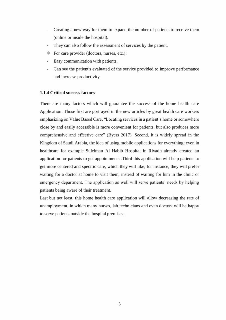
1.1.4 Critical success factors
There are many factors which will guarantee the success of the home health care
Application. Those first are portrayed in the new articles by great health care workers
emphasizing on Value Based Care, “Locating services in a patient’s home or somewhere
close by and easily accessible is more convenient for patients, but also produces more
comprehensive and effective care” (Byers 2017). Second, it is widely spread in the
Kingdom of Saudi Arabia, the idea of using mobile applications for everything; even in
healthcare for example Suleiman Al Habib Hospital in Riyadh already created an
application for patients to get appointments .Third this application will help patients to
get more centered and specific care, which they will like; for instance, they will prefer
waiting for a doctor at home to visit them, instead of waiting for him in the clinic or
emergency department. The application as well will serve patients’ needs by helping
patients being aware of their treatment.
Last but not least, this home health care application will allow decreasing the rate of
unemployment, in which many nurses, lab technicians and even doctors will be happy
to serve patients outside the hospital premises.

4
1.1.5 Organization chart and responsibilities
Figure 1-1 Organization chart
1.2 General rules (Assumptions)
In order to use the home health care application, the patients should be able to use smart
phones, and the hospitals in turn should market the application in way for patients to be
informed about it. In the next level, hospitals must familiarize the patients and the
healthcare providers with the minimum knowledge in terms of using the application. If
the patient is old and does not have the correct knowledge to make use of the app, an IT
person should help him on the phone or visit him at home in difficult cases.

5
Chapter 2 : LITERATURE REVIEW
2.1 INTRODUCTION If we look at Saudi Arabia market regarding healthcare, we can found that there is a lot
of centers that provide home health care, one of them is, SALAM home health care.
Salam medical is a standalone home healthcare company and not associated with a
hospital and has many services including, Elderly Care at home, neurology care at home
and medication management. But in Salam center, there is no use for a mobile phone
application that helps patients request health care services to home (Salam Medical, n.d.,
para.1).
There is also on prestigious center called “Dar Al Shifa Home Care” In Kuwait that
offers a lot of post hospitalizations services for patients. However, it also lacks the use
of a mobile application to do the work (Dar Al Shifa Home Care, n.d., para.1).
Mobile health applications allow healthcare providers to connect with patients and staff
more quickly and easily, reaching out to them on the device of their choosing and at
their convenience. Apps designed for a smartphone, tablet, or even a smartwatch also
allow users to access information when and where they need it, reducing time wasted
searching for that data and boosting both engagement and satisfaction rates (Malvey&
Slovensky, 2016).
In this chapter, we will mention some application that have the same approach it is an
m-health application such as qural, alrazy group for home healthcare and 7keema
application.
2.2 LITERATURE REVIEW
2.2.1 Qural
Qural is a smart healthcare app. Qural healthcare app allows doctors to manage their
entire medical practice right from patient scheduling, electronic medical records
(EMR)(EHR), patient tracking etc. using any mobile device. Qural can provide
telemedicine services for patients and their physicians.
One of the best features included in Qural app is that patients can manage their entire
family's medical and health information. Patients also can search for doctors based on
specialization or location, connect with them and keep track of their medical and health
information (Qural health care. n.d., para.2).

6
2.2.2 Al-Razy group for home healthcare
Al-Razy Group for Home Health Care is a licensed company started its activities in
March 2013. The company is regularly audited by the official Health, financial and
administrative governmental authorities in Egypt. In addition to that, Al-Razy group for
home healthcare work with hospitals to serve their patients after discharge (Alrazy
group, n.d.)
2.2.3 7kemma
Is an application that provides home health care services through a team of licensed
nurses of both sexes. It provides services 24 hours a day in Egypt by locating the patient
and providing care to him by his nearest nurse (7keema, n.d., para.1).
2.3 SIMILAR TOOLS COMPARISON
Table below table shows a comparison between our application tools and other similar
application tools.
Features Qural
Al-Razy group
7kemma
HHCS
Home care services Managed by the
hospital
Direct access to lab results
Chat and communication
between patient and doctors
Android mobile platform
(Samsung, LG etc.)
Table 2-1 comparison with similar application table
The most important feature in our application that is managed by the hospital itself, this
will help the two parties, the patient and the hospital to have good management with
great communication facilities referenced by the case of the patient and his file
information from the hospital. Direct access to the lab results can also add a greater value
in our home healthcare services application.

7
Chapter 3 : SYSTEM ANALYSIS AND SPECIFICATION
3.1 Introduction
In each model of system development there are four phases, one of which is analysis,
which is the most important phase in the life cycle of systems development.
System analysis describes what a system should do to meet the needs of users where
system requirements are defined. The purpose of Systems Analysis is to understand a
system, which enables us to understand the structure and behavior of the system.
3.2 Modeling used
In this project, we used the prototyping model which I can through its iterative
development of requirements, it have many advantages and disadvantages (Sparrow,
n.d., para. 1).
Figure 3-1 Prototyping model
❖ Advantages of Prototype model
1. Users are actively involved in the development
2. Reduced time and costs
3. Errors can be detected much earlier
❖ Disadvantages of Prototype model
1. User confusion.
2. Developers do not want to always involvement of clients.
3. Many changes by customers may disrupt the development team

8
3.3 Description of Data Flow Diagram (DFD)
The concept behind Data flow diagrams (DFDs) is to identify the relationships between
components of the system. DFDs can be used to explain complex technical view of the
system in a simple way that can be understood by non-technical individuals. However,
DFDs can help system designers and others in the analysis stages of the system.
Data Flow Diagram consists of four major components, entities, processes, data stores
and data flows (Donald, 2012).
3.3.1 Context Diagram
Figure 3-2 Context Diagram
A context diagram only shows the top level, As shown above (see figure3.2) in the figure
the diagram describes in a general way how the system works and interact with each
main component. Patients, care providers and hospital are the main components of the
system; they interact with each other though the home healthcare services application.

9
3.3.2 Overview diagram (level 0)
Figure 3-3 level 0 diagram
A level 0 diagram as shown above (see figure3.3) it describes how to components in the
system interact in detail.
3.3.3 Detailed DFDs
Basically, a DFD is a picture of movement of data between external entities, processes
and data store within a system.
- External Entity: Represents a human, subsystem or system (rectangle).
- Process: A process is a business activity or function where the manipulation and
transformation of data takes place (circle).
- Data Store: Represents the storage of persistent data required or/and produced
by the process.
- Data Flow: Represents the flow of information, with its direction represented by
an arrow head that shows at the end of flow connector.

10
Figure 3-4 Data Flow Diagram (DFD)
As shown in figure above (see figure 3.4) after the authentication process is done
correctly,
hospital can add patient, add doctor or add lab tests then it will be stored in database.
patient login to the application with his email and password and after that he can chose
a service request if it home based service it should select the doctor and schedule the
time and date with address, or if the service is to check the lab results it dependent on
the hospital has added or not, also patients can evaluate services that will be used in
improving the system.
Care provider can complete the requested services to patient.

11
3.4 Unified Modelling Language (UML) Diagram
The Unified Modeling Language (UML) is a general-purpose, developmental, modeling
in the field of software engineering which is intended to provide a standard way to
visualize the design of a system (Unified Modeling Language User Guide,2005, p. 496).
We prepare UML diagrams to understand HHCS system in better and simple way. Also,
a single diagram is not enough to cover all aspects of the system. So, structures various
kinds of diagrams including structural and behavioral diagrams to cover most of the
aspects of a system.
3.4.1 Usecase Diagram
Use Cases describe the behavior of the system, it is an effective requirement capture
technique that makes requirements available for review by avoiding any implementation
bias in the requirements.
Use Case itself is an interaction that a User or other System has with the system that is
being designed, in order to achieve a goal. The term Actor is used to describe the person
or system that has the goal, this term is used to emphasize the fact that any person or
system could have the goal. In addition to that they are used to describe the relationships
among the functionalities and their internal/external actors (WhatIs, n.d., para. 1).
Figure 3-5 Use case diagram

12
3.4.1.1 Patient usecase diagram
Figure 3-6 Patient use case diagram
3.4.1.2 Care Provider usecase diagram
Figure 3-7 Doctor usecase diagram

13
3.4.1.3 Hospital usecase diagram
Figure 3-8 Hospital (admin) usecase diagram
3.4.2 Class Diagram
A class diagram describes the structure of the system and defines the methods and
variables in an object (Lucidchart, 01 November,2018).

14
Figure 3-9 Class diagram
3.4.3 Sequence Diagram
Sequence diagrams are a kind of interaction diagram, because they describe how—and
in what order—a group of objects works together. Sequence diagrams are sometimes
known as event diagrams or event scenarios.
The sequence diagram is used primarily to show the interactions between objects in the
sequential order that those interactions occur (smartdraw, n.d., para. 1).

15
3.4.3.1 Hospital (Admin) Sequence diagram
Figure 3-10 Hospital sequence diagram
3.4.3.2 Patient Sequence diagram
Figure 3-11 Patient sequence diagram
3.4.3.3 Doctor Sequence diagram

16
Figure 3-12 Doctor sequence diagram
3.4.4 Activity Diagram
An activity diagram describes the behavior of the system and visually presents a series
of actions or flow of control in a system similar to a flowchart or a data flow diagram
(Lucidchart, 06 September, 2018).
3.4.4.1 Hospital (Admin) activity diagram

17
Figure 3-13 Hospital activity diagram
3.4.4.2 Patient activity diagram
Figure 3-14 Patient activity diagram

18
3.4.4.3 Doctor activity diagram
Figure 3-15 Doctor activity diagram
3.5 Entity Relationship Diagram (ERD)
An entity relationship diagram (ERD) shows the relationships of entity sets stored in a
database. An entity in this context is a component of data. In other words, ER diagrams
illustrate the logical structure of databases (Rouse, 2018).
The ER data model has three basic notions: entity-sets, relationship sets and attributes.
3.5.1 Description of Entities
1. Name: Hospital (admin)
Attributes: AdminID: Unique ID
Email: the email of hospital.
Password: hospital password to login to application.
Fname: the first name of the hospital.
Lname: the last name of the hospital.

19
2. Name: Patient
Attributes: patientID: Unique ID
fname: the first name of patient.
Lname: the last name of the patient.
Email: the email of patient.
Password: patient password to login to application.
Type: the type of the user.
3. Name: Doctor
Attributes: doctorID: Unique ID
fname: the first name of doctor.
Lname: the last name of the doctor.
Email: the email of doctor.
Password: doctor password to login to application.
Shiftinfo: the shift of doctor.
Specialty: specialty of the doctor.
Type: the type of the user.
4. Name: Service
Attributes: ServiceID: Unique ID
Completed: the service is completed or not
DoctorID: the doctor ID
PatientID: the patient ID
Rate: rate or evaluate of services
Location: location of patient
Time: the time of service.
reachDetails: details of the appointment whether a mobile number or skype
account
5. Name: Lab Test
Attributes: storagelocation: Unique ID
PatientID: the patient ID

20
3.5.2 Description of relations
- Admin Account
In our application, we have only one (and only one) admin account which can add zero or many
(Patients, Doctors and LabTests results for the patients).
- Doctor Account
The Doctor account could be added by the admin, as explained previously, and able to complete zero
or many services (which were created by the patient and associated with him).
- Patient Account
The patient account is the main focus of the app, hence it has many functionalities.
• Patient has zero or one LabTest result.
• Patient has zero or many Services associated with him.
• Patient can request zero or many Services.
• Patient can rate (give feedback) on zero or many Services.

21
3.5.3 Drawing ERD
Figure 3-16 ERD diagram

22
Chapter 4 : SYSTEM DSIGN
4.1 Description of procedures and function
In the description of procedure and function we will draw a flowchart diagram that
will clear up all the procedures and function of patient’s in the system (Lucidchart,
06 September, 2018).
Figure 4-1 Flowchart diagram
In the above figure (see fig. 4.1), after the login and correct authentication, the user
(patient) will have the choice to either give a feedback or suggestion about something
or choose a service. The healthcare application will call other system in the hospital to
check the availability of the service. If it is available the care will be provided for the
patient.

23
4.2 Relation database schema
A relational database is a group of data organized in the form of tables. These tables will
help programs to add, fetch, and remove data from them. Data can be accessed or
reassembled in many different ways without having to rebuild or reorganize the database
tables (Nguyen, 04 October, 2017).
4.2.1 Tables
Several tables are required to implement our system the following is the list tables:
- Hospital (Admin) table: The hospital table contains hospital information and
login information for hospital.
- Patient table: contains patient information and login information for patient.
- Doctor table: contains doctor information and login information for doctor.
- Services table: represents all data related to services that could offer for care
provider.
- Lab test table: represents information about the result of lab test that uploaded
by the hospital.
4.2.2 Attributes
4.2.2.1 Hospital (Admin) Attributes
Attribute Name Data Type Constraints
Admin ID String Primary key
fname String lname String
Email String Password String
Table 4-1 Hospital attributes table
4.2.2.2 Patient Attributes
Attribute Name Data Type Constraints
Patient ID String Primary key
fname String lname String
Email String
Password String
type String Table 4-2 Patient attributes table

24
4.2.2.3 Doctor Attributes
Attribute Name Data Type Constraints Doctor ID String Primary key
fname String lname String
Email String
Password String
Shiftinfo String
specialty String type String
Table 4-3 Doctor attributes table
4.2.2.4 Services Attributes
Attribute Name Data Type Constraints Service ID String Primary key
Completed Boolean
Doctor ID String Foreign key Patient ID String Foreign key
reachDetails String Rate number
Location String
time String Table 4-4 Services attributes table
4.2.2.5 Lab test Attributes
Attribute Name Data Type Constraints
storagelocation String Primary key
Patient ID String Foreign key Table 4-5 Lab test attributes table
4.2.3 Relations
The relation between all tables is set by the use of primary key and foreign keys.
In order for two tables to be linked together, a primary key attribute in the first one
should be a foreign key in the second one and vice versa. A draw of a relational database
schema will show the relations between tables.

25
Figure 4-2 Relational Database Schema
4.3 Hardware and software requirements
❖ Software requirements:
Android studio
Android Studio is the official integrated development environment (IDE) for developing
for the Android platform. It was announced on May 16, 2013 at the Google I/O
conference. Android Studio is freely available under the Apache License 2.0.
Android emulator:
An Android emulator is an Android Virtual Device (AVD) that represents a specific
Android device. The emulator gives the look, feel and functionality of an android device
virtually. You can use an Android emulator as a target platform to run and test your
Android applications on your PC without the need of an android phone or any android
device

26
Firebase:
Firebase is platform which allow to build web and mobile applications without server-
side programming language. It combines Analytics, Database, Authentication, Storage,
Hosting, Crash Reports etc.
Google is trying to Integrate all basic services needed for an android app through
Firebase.
Draw.io
Draw.io is an open source technology stack for building diagramming applications, and
the world’s most widely used browser-based end-user diagramming application.
❖ Hardware requirements
Android phone or tablet: the android phone device will be used to install the application,
open it and use it.

27
Chapter 5 : IMPLEMENTATION AND TESTING
5.1 Introduction
In this chapter we focus on the procedures followed in the system, the design of the
interfaces and the way they are linked to the database.
5.2 Procedures
The project has so many functions that are very important. Here, we will mention the
most two important functions from our point of view:
1. SignInUsingFirebaseAuth()
This is the most important function as without it the application won’t be working at all.
All the actions and functionalities of the app (except for a patient to register himself) are
limited to authenticated users only. So that, all their data are properly linked to them.
This function allows the user to properly authenticate himself and login to the app to
make use of its various functionalities.
2. RequestNewService()
In the second place comes the RequestNewService() functions. This function represents
the core functionality of the app, where a patient can request the service remotely
through the app.
The function takes the input data from the patient and creates a new record for the service
and makes it available to the selected service provider to take the proper action.
5.3 Layouts
In our system we have hospital(admin), patient and doctor, each one has a different
layout.
5.3.1 Hospital (admin) layout

28
5.3.1.1 Hospital sign-in interface
One of the most important interfaces in our system.
Figure 5-1 Sign-in interface
5.3.1.2 Hospital homepage interface
This page contains a list of all completed services and services evaluated by the patient
Figure 5-2 Hospital homepage interface

29
5.3.1.3 Hospital list of patient’s list interface
This interface contains a list of registered patients, and through it the hospital can add a
new patient.
Figure 5-3 Hospital patients’ list interface
5.3.1.4 Hospital list of doctors’ list interface
This interface contains a list of registered doctors’, and through it the hospital can add a
new doctor.
Figure 5-4 Hospital doctors’ list interface

30
5.3.2 Patient layout
5.3.2.1 Register a new patient interface
Through the homepage of the application, patient can register by select NEW
PATIENT? REGISTER HERE and fill in all this information.
Figure 5-5 Patient register interface
5.3.2.2 Patient homepage interface
In this interface, all the completed services will be here to evaluate.
Figure 5-6 Patient homepage interface

31
5.3.2.3 Patient lab tests interface
lab tests interface contains the results of lab test you did it in hospital that will be
uploaded by the hospital itself.
Figure 5-7 lab tests interface
5.3.2.4 Patient services interface
Services interface contains three services which you can select from them what you
want.
Figure 5-8 Services interface

32
5.3.3 Doctor layout
5.3.3.1 new services interface
After the doctor log-in by the email and password, the first interface contains a list of
services requested by the patient.
Figure 5-9 New services interface
5.3.3.2 completed service interface
The second interface of the doctor is completed services interface which contain all the
services completed and it evaluate.
Figure 5-10 Completed services interface

33
Figure 5-12 Doctor registration interface
5.4 Reports layouts
- In the hospital (admin) account, when you want to add a new patient or doctor
you should to insert some information’s about him then click save to create the
account.
After you register patient or doctor successfully you will get these messages,
Figure 5-13 Patient added successfully interface
Figure 5-11 Patient registration interface

34
Figure 5-14 Doctor added successfully interface
- In the patient account, when you want to request a new service either home-
based service or communicate with a doctor service, you should to insert all the
details (include the name of care provider, address, date and time, etc.) of the
requested service then click request service to send it to care provider which you
previously selected.
Figure 5-15 Request service interface

35
5.5 Reports
5.5.1 Hospital (admin) Database
Table 5-1 Hospital (admin) Database
5.5.2 Patients Database
Table 5-2 Patients Database
5.5.3 Doctors Database
Table 5-3 Doctors Database
5.5.4 Services Database
Table 5-4 Services Database
5.5.5 Lab tests Database
Table 5-5 Lab tests Database

36
Chapter 6 : CONCULSION AND FUTURE WORK While it is very important to mention the positive impact on the hospital and the
healthcare community reflected by the development of the home healthcare service
application, we can’t forget its impact on patients that are being very comfortable at their
home when the care provider can come to their home to help them with any service
already requested. Furthermore, the mobile phone in the hand of patients is not now just
a machine to call or to play games but it is a medium to see their lab results without
going to archive department where records are stored and wait all day to get their results
on papers where are also risk to be lost.
This application has more dimensions as it can be expanded, more features can be added.
The idea of building more features on top of this application like a history health book
for the whole family shared with family parties and the family doctors. Other feature
could be the way to upgrade and enhance the application is the video call between the
patient and his doctor so they speak face to face like an online consultation. In addition
to that one area that will improve greatly the application is to integrate a diet system of
foods specific for the patient.
Healthcare is the mirror of the society, if the healthcare is good the society is good. We
should serve patients by the all possible ways because nobody knows, one day we might
be at their places.

37
References
[1] MALVEY, D., & SLOVENSKY, D. J. (2016). MHEALTH: Transforming healthcare. New
York: Springer.
[2] Byers, J. Muchmore, S. (2017). The healthcare of tomorrow will move away from
hospitals. Healthcare Dive. Retrieved 8 February 2018, from
https://www.healthcaredive.com/news/the-healthcare-of-tomorrow-will-move-away-from-
hospitals/510131/
[3] Salam Medical | Home Health Care. (n.d.). Retrieved from http://www.salammedical.com/
[4] Dar Al Shifa Home Care. (n.d.). Retrieved from
http://www.daralshifa.com/Subsidiaries/DASH-Home-Care
[5] What can Qural do for you? (n.d.). Retrieved from https://www.qural.in/
[6] Home Health Care Service Request. (n.d.). Retrieved from
https://www.alrazygroup.com/en/index.php
[7] 7keema. (n.d.). Retrieved from http://7keema.com/
[8] Sparrow, P. (n.d.). Prototype Model: Advantages and Disadvantages. Retrieved November
18, 2018, from https://www.ianswer4u.com/2011/11/prototype-model-advantages-and.html
[9] DFD_over_Flowcharts.pdf. (2012). Donald, S. Ratandon.mysite.syr.edu. Retrieved 22
February 2018, from https://ratandon.mysite.syr.edu/cis453/notes/DFD_over_Flowcharts.pdf
[10] Unified Modeling Language User Guide, The (2 ed.). Addison-Wesley. 2005. p. 496.
[11] What is use case diagram (UML use case diagram)? - Definition from WhatIs.com. (n.d.).
Retrieved from https://whatis.techtarget.com/definition/use-case-diagram
[12] UML Class Diagram Tutorial. (2018, November 01). Retrieved from
https://www.lucidchart.com/pages/uml-class-diagram
[13] Sequence Diagram. (n.d.). Retrieved from https://www.smartdraw.com/sequence-
diagram/
[14] UML Activity Diagram Tutorial. (2018, September 06). Retrieved from
https://www.lucidchart.com/pages/uml-activity-diagram
[15] Rouse, M. (2018). Entity relationship diagram (ERD). Techtarget. Retrieved 28 Mar
2018, from https://searchdatamanagement.techtarget.com/definition/entity-relationship-
diagram-ERD
[16] What is a Flowchart. (2018, September 06). Retrieved from
https://www.lucidchart.com/pages/what-is-a-flowchart-tutorial
[17] Nguyen, K. (2017, October 04). Relational Database Schema Design Overview – Kim
Nguyen – Medium. Retrieved from https://medium.com/@kimtnguyen/relational-database-
schema-design-overview-70e447ff66f9

38
Appendixes

39
Appendix A
A sample of the questionnaire containing five questions was answered by 70
members of the community
Good health is a way of good life, however, vision 2030 in Saudi Arabia aims to expand
the ways of providing home health care, this application is designed to provide home
health care to people in remote areas or to people who can’t go to the hospital because
of their working conditions or their health doesn’t allow them to travel or go to the
hospital.
Q1: Do you have a cost problem for the hospital?
• Yes
• No
• Maybe
Result:
Q2: Do you have a problem when you go to the hospital because you live in remote
areas or working conditions?
• Yes
• No
• Maybe
Result:

40
Q3: What do you think of keeping the lab results or imaging reports of patient and
send it through the application without going to the hospital to receive?
• Yes
• No
• Maybe
Result:
Q4: Have you ever heard of an application that helps patients without going to the
hospital?
• Yes
• No
• Maybe
Result:
Q5: If this application is implemented, do you think it will ease the burden of the
patient even slightly?
• Yes
• No
• Maybe
Result:

41
Appendix B
1. Program written in Java language to main activity in our project to sign-in and
sign-out.
import android.app.ProgressDialog; import android.content.Intent; import android.os.Bundle; import android.support.annotation.NonNull; import android.support.v7.app.AppCompatActivity; import android.text.TextUtils; import android.util.Log; import android.view.View; import android.widget.Button; import android.widget.EditText; import android.widget.ProgressBar; import android.widget.Toast; import com.google.android.gms.tasks.OnCompleteListener; import com.google.android.gms.tasks.Task; import com.google.firebase.auth.AuthResult; import com.google.firebase.auth.FirebaseAuth; import com.google.firebase.auth.FirebaseUser; import com.google.firebase.firestore.DocumentReference; import com.google.firebase.firestore.DocumentSnapshot; import com.google.firebase.firestore.FirebaseFirestore; public class MainActivity extends AppCompatActivity { private String TAG = "MainActivity"; //defining view objects private EditText editTextEmail; private EditText editTextPassword; private ProgressDialog progressDialog; //defining firebaseauth object private FirebaseAuth firebaseAuth; private FirebaseUser currentUser; private String currentUserType; @Override protected void onCreate(Bundle savedInstanceState) { super.onCreate(savedInstanceState); setContentView(R.layout.activity_main); //initializing firebase auth object and get current user firebaseAuth = FirebaseAuth.getInstance(); currentUser = firebaseAuth.getCurrentUser(); //check if user is signed in or not if (currentUser != null) { // user already signed in // get user type and redirect if user already signed in getUserTypeAndRedirect(); } else {

42
//initializing views progressDialog = new ProgressDialog(this); editTextEmail = findViewById(R.id.editTextEmail); editTextPassword = findViewById(R.id.editTextPassword); // hide the progressbar ProgressBar signInProgressBar = findViewById(R.id.signInProgressBar); signInProgressBar.setVisibility(View.GONE); // define the sign in button and its action Button signInButton = findViewById(R.id.signInButton); signInButton.setOnClickListener(new View.OnClickListener() { @Override public void onClick(View v) { //calling sign in method on click signInUser(); } }); // define the register button and its action Button registerButton = findViewById(R.id.registerButton); registerButton.setOnClickListener(new View.OnClickListener() { @Override public void onClick(View v) { //calling sign in method on click Intent addPatient = new Intent(getBaseContext(), AddPatientActivity.class); addPatient.putExtra("isAdmin", false); startActivity(addPatient); } }); } } /* Helper method to Sign In user using Firebase Auth Using Email and Password */ private void signInUser() { //getting email and password from edit texts String email = editTextEmail.getText().toString().trim(); String password = editTextPassword.getText().toString().trim(); //checking if email and passwords are empty if (TextUtils.isEmpty(email)) { Toast.makeText(this, R.string.please_enter_email, Toast.LENGTH_LONG).show(); return; } if (TextUtils.isEmpty(password)) { Toast.makeText(this, R.string.please_enter_password, Toast.LENGTH_LONG).show(); return; } //if the email and password are not empty //displaying a progress dialog

43
progressDialog.setTitle(getString(R.string.signing_in)); progressDialog.setMessage(getString(R.string.please_wait)); progressDialog.show(); // Connect to Firebase Auth to sign in user using Email and Password firebaseAuth.signInWithEmailAndPassword(email, password) .addOnCompleteListener(this, new OnCompleteListener<AuthResult>() { @Override public void onComplete(@NonNull Task<AuthResult> task) { //checking if success if (task.isSuccessful()) { //display some message here Toast.makeText(getBaseContext(), getString(R.string.successfully_signed_in), Toast.LENGTH_LONG).show(); getUserTypeAndRedirect(); } else { //display some message here Toast.makeText(getBaseContext(), getString(R.string.error) + task.getException().getLocalizedMessage(), Toast.LENGTH_LONG).show(); } progressDialog.dismiss(); } }); } /* Redirect user based on his account type */ private void getUserTypeAndRedirect() { // Get user type FirebaseFirestore db = FirebaseFirestore.getInstance(); currentUser = firebaseAuth.getCurrentUser(); if (currentUser != null) { // Connect to database and get the currentUser information DocumentReference docRef = db.collection("users").document(currentUser.getUid()); docRef.get().addOnCompleteListener(new OnCompleteListener<DocumentSnapshot>() { @Override public void onComplete(@NonNull Task<DocumentSnapshot> task) { if (task.isSuccessful()) { DocumentSnapshot document = task.getResult(); if (document.exists()) { // if the user exists on the database, check his type String userType = document.getString("type"); Log.d(TAG, "DocumentSnapshot data: " + userType); currentUserType = userType; // redirect the user based on his type redirectUser(); } else { Log.d(TAG, "No such document"); userSingOut(); } } else { Log.d(TAG, "get failed with ", task.getException()); userSingOut(); } } });

44
} } /* Helper method to redirect the user to the proper Activity based on the user type */ private void redirectUser() { Log.d(TAG, "Current userType: " + currentUserType); if (currentUserType != null) { switch (currentUserType) { case "admin": // goto home activity Intent adminIntent = new Intent(getBaseContext(), HomeAdminActivity.class); startActivity(adminIntent); finish(); break; case "doctor": // goto home activity Intent doctorIintent = new Intent(getBaseContext(), HomeDoctorActivity.class); startActivity(doctorIintent); finish(); break; case "patient": // goto home activity Intent patientIntent = new Intent(getBaseContext(), HomePatientActivity.class); startActivity(patientIntent); finish(); break; default: Toast.makeText(this, R.string.invalid_user_type, Toast.LENGTH_LONG).show(); userSingOut(); break; } } } /* Helper method for user sign ou */ public void userSingOut() { try { firebaseAuth.signOut(); Intent intent = new Intent(getBaseContext(), MainActivity.class); startActivity(intent); } catch (Exception e) { e.printStackTrace(); } } }
2. Program written in Java language to add patient in the application.
import android.content.Intent;

45
import android.content.SharedPreferences; import android.graphics.Bitmap; import android.graphics.BitmapFactory; import android.net.Uri; import android.os.Bundle; import android.support.annotation.NonNull; import android.support.v7.app.AppCompatActivity; import android.text.TextUtils; import android.util.Log; import android.view.Menu; import android.view.MenuItem; import android.view.View; import android.widget.Button; import android.widget.EditText; import android.widget.ImageView; import android.widget.Toast; import com.google.android.gms.tasks.OnCompleteListener; import com.google.android.gms.tasks.OnFailureListener; import com.google.android.gms.tasks.OnSuccessListener; import com.google.android.gms.tasks.Task; import com.google.firebase.auth.AuthResult; import com.google.firebase.auth.FirebaseAuth; import com.google.firebase.auth.FirebaseUser; import com.google.firebase.auth.UserProfileChangeRequest; import com.google.firebase.firestore.DocumentReference; import com.google.firebase.firestore.FirebaseFirestore; import com.google.firebase.storage.FirebaseStorage; import com.google.firebase.storage.StorageReference; import com.google.firebase.storage.UploadTask; import java.io.ByteArrayOutputStream; import java.io.FileNotFoundException; import java.util.Objects; import java.util.regex.Matcher; import java.util.regex.Pattern; public class AddPatientActivity extends AppCompatActivity { private String TAG = "AddPatientActivity"; /** * Declare the TextViews */ private EditText firstNameView; private EditText lastNameView; private EditText emailView; private EditText passwordView; private ImageView labTestImageView; private Bitmap bitmap; private String firstName; private String lastName; private String email; private String password; //defining firebaseauth object private FirebaseAuth firebaseAuth; private FirebaseUser newUser;

46
private SharedPreferences adminPref; private SharedPreferences.Editor adminPrefEditor; private boolean isAdmin; private int RESULT_LOAD_IMG = 100; @Override protected void onCreate(Bundle savedInstanceState) { super.onCreate(savedInstanceState); setContentView(R.layout.activity_add_patient); // Find relevant views that will display data firstNameView = findViewById(R.id.patientFirstName); lastNameView = findViewById(R.id.patientLastName); emailView = findViewById(R.id.patientEmail); passwordView = findViewById(R.id.patientPassword); labTestImageView = findViewById(R.id.labTestImage); //initializing firebase auth object firebaseAuth = FirebaseAuth.getInstance(); // Save current position in ViewPager adminPref = getPreferences(MODE_PRIVATE); adminPrefEditor = adminPref.edit(); adminPrefEditor.putBoolean("restorePosition", true); adminPrefEditor.apply(); isAdmin = Objects.requireNonNull(getIntent().getExtras()).getBoolean("isAdmin"); Log.d(TAG, "Opened by Admin? " + isAdmin); if (!isAdmin) { setTitle(getString(R.string.title_register_patient)); } Button loadImage = findViewById(R.id.loadlabTest); loadImage.setOnClickListener(new View.OnClickListener() { @Override public void onClick(View v) { // Create intent to Open Image applications like Gallery, Google Photos Intent galleryIntent = new Intent(Intent.ACTION_PICK, android.provider.MediaStore.Images.Media.EXTERNAL_CONTENT_URI); // Start the Intent startActivityForResult(galleryIntent, RESULT_LOAD_IMG); } }); Button setChanges = findViewById(R.id.setChanges); setChanges.setOnClickListener(new View.OnClickListener() { @Override public void onClick(View v) { registerUser(); } }); } @Override protected void onActivityResult(int requestCode, int resultCode, Intent data) {

47
super.onActivityResult(requestCode, resultCode, data); // When an Image is picked if (requestCode == RESULT_LOAD_IMG) { if (resultCode == RESULT_OK && null != data) { // Get the Image from data Uri selectedImage = data.getData(); try { assert selectedImage != null; bitmap = BitmapFactory.decodeStream(getContentResolver().openInputStream(selectedImage)); GlideApp.with(this) .load(bitmap) .placeholder(R.drawable.img_placeholder) .into(labTestImageView); } catch (FileNotFoundException e) { e.printStackTrace(); } labTestImageView.setImageBitmap(bitmap); } else { Toast.makeText(this, R.string.no_image_picked, Toast.LENGTH_LONG).show(); } } } // Menu Methods @Override public boolean onCreateOptionsMenu(Menu menu) { MenuItem item = menu.add(Menu.NONE, 0, Menu.NONE, getString(R.string.save)); item.setIcon(android.R.drawable.ic_menu_save); item.setShowAsAction(MenuItem.SHOW_AS_ACTION_IF_ROOM); return true; } @Override public boolean onOptionsItemSelected(MenuItem item) { switch (item.getItemId()) { case 0: registerUser(); return true; case android.R.id.home: if (!isAdmin) { Intent intent = new Intent(getBaseContext(), MainActivity.class); startActivity(intent); finish(); } else { break; } return true; default: return super.onOptionsItemSelected(item); } return super.onOptionsItemSelected(item);

48
} /* Register User with FirebaseAuth */ private void registerUser() { // Read from input fields // Use trim to eliminate leading or trailing white space firstName = firstNameView.getText().toString().trim(); lastName = lastNameView.getText().toString().trim(); email = emailView.getText().toString().trim(); password = passwordView.getText().toString().trim(); // Check if all the fields in the editor are filled if (TextUtils.isEmpty(firstName) && TextUtils.isEmpty(lastName) && TextUtils.isEmpty(email) && TextUtils.isEmpty(password)) { Toast.makeText(this, R.string.fill_all_fields, Toast.LENGTH_LONG).show(); // make sure we don't continue the code return; } //checking if any field is empty if (TextUtils.isEmpty(firstName) || TextUtils.isEmpty(lastName)) { Toast.makeText(this, R.string.please_enter_name, Toast.LENGTH_LONG).show(); return; } if (TextUtils.isEmpty(email) || !isEmailValid(email)) { Toast.makeText(this, R.string.enter_valid_email, Toast.LENGTH_LONG).show(); return; } if (TextUtils.isEmpty(password)) { Toast.makeText(this, R.string.please_enter_password, Toast.LENGTH_LONG).show(); return; } // Connect to Firebase Auth to create new user using Email and Password firebaseAuth.createUserWithEmailAndPassword(email, password) .addOnCompleteListener(this, new OnCompleteListener<AuthResult>() { @Override public void onComplete(@NonNull Task<AuthResult> task) { //checking if success if (task.isSuccessful()) { // Sign in success //display some message here newUser = firebaseAuth.getCurrentUser(); if (firebaseAuth.getCurrentUser() != null) { // Update Display Name String fullName = firstName + " " + lastName; UserProfileChangeRequest profileUpdates = new UserProfileChangeRequest.Builder() .setDisplayName(fullName).build(); if (newUser != null) { newUser.updateProfile(profileUpdates); } savePatient(newUser.getUid());

49
} } else { //display some message here Toast.makeText(getBaseContext(), getString(R.string.error) + Objects.requireNonNull(task.getException()).getLocalizedMessage(), Toast.LENGTH_LONG).show(); } } }); } /** * Save new Patient from EditText fields to Firestore */ private void savePatient(String newUID) { FirebaseFirestore db = FirebaseFirestore.getInstance(); DocumentReference patientRef = db.collection("users").document(newUID); patientRef.set(new Patient(firstName, lastName, email, password)) .addOnSuccessListener(new OnSuccessListener<Void>() { @Override public void onSuccess(Void aVoid) { Toast.makeText(AddPatientActivity.this, R.string.patient_add, Toast.LENGTH_LONG).show(); if (isAdmin) { signAdmin(); } } }); // Check if new image loaded if(bitmap != null) { // Get the data from an ImageView as bytes ByteArrayOutputStream baos = new ByteArrayOutputStream(); bitmap.compress(Bitmap.CompressFormat.JPEG, 100, baos); byte[] data = baos.toByteArray(); // Upload lab test image to Firestore Storage StorageReference mountainsRef = FirebaseStorage.getInstance().getReference(newUID + ".jpg"); UploadTask uploadTask = mountainsRef.putBytes(data); uploadTask.addOnFailureListener(new OnFailureListener() { @Override public void onFailure(@NonNull Exception exception) { // Handle unsuccessful uploads } }).addOnSuccessListener(new OnSuccessListener<UploadTask.TaskSnapshot>() { @Override public void onSuccess(UploadTask.TaskSnapshot taskSnapshot) { // taskSnapshot.getMetadata() contains file metadata such as size, content-type, etc. // ... } }); } finish(); }

50
public boolean signAdmin() { // Connect to Firebase Auth to sign in user using Email and Password String email = "[email protected]"; String password = "123456"; boolean result = false; firebaseAuth.signInWithEmailAndPassword(email, password) .addOnCompleteListener(this, new OnCompleteListener<AuthResult>() { @Override public void onComplete(@NonNull Task<AuthResult> task) { //checking if success if (task.isSuccessful()) { boolean result = true; } } }); return result; } /** * method is used for checking valid email id format. */ public static boolean isEmailValid(String email) { String expression = "^[\\w\\.-]+@([\\w\\-]+\\.)+[A-Z]{2,4}$"; Pattern pattern = Pattern.compile(expression, Pattern.CASE_INSENSITIVE); Matcher matcher = pattern.matcher(email); return matcher.matches(); } @Override public void onBackPressed() { moveTaskToBack(true); } }

51
Appendix C
This appendix contains a screenshot of database which used in this project, we user
authentication, cloud storage and firestore in Firebase platform.
• Authentication interface
We used it authenticate for log-in.
• cloud storage interface
We used it to store the information of users and services.

52
• firestore We used it to store lab tests results.
Top Related