


Languages
Pages
Legal

1
ENVIRONMENTAL IMPACT ASSESSMENT
PROJECT BRIEF FOR THE CONSTRUCTION AND OPERATION OF
A REMANUFACTURING FACTORY
ON PLOT NO. 2350/M, LUSAKA INTERNATIONAL AIRPORT ROAD, LUSAKA
FOR
Hitachi Construction Machinery
Zambia Co., Ltd
Final Report: November 2010
PO Box: 37928, Lusaka, Zambia
Telephone: 260 21 1 227176
Fax: 260 21 1 229555
Email: [email protected]

2
Table of Contents
LIST OF FIGURES ....................................................................................................................................................... 4
LIST OF TABLES ........................................................................................................................................................ 4
1.0 INTRODUCTION ............................................................................................................................................. 5
2.0 LEGISLATIVE REQUIREMENTS ................................................................................................................ 7
2.1 ZAMBIAN ENVIRONMENTAL POLICY ............................................................................................................... 7
2.2 ZAMBIAN ENVIRONMENTAL LEGISLATION ...................................................................................................... 7
2.3 ZAMBIAN REQUIREMENTS FOR ENVIRONMENTAL ASSESSMENTS .................................................................... 8
2.4 OTHER APPLICABLE LEGISLATION .................................................................................................................. 8
3.0 DESCRIPTION OF THE SITE AND EXISTING ENVIRONMENT ........................................................ 11
3.1 SITE LOCATION AND VICINITY ...................................................................................................................... 11
3.2 LAND OWNERSHIP AND TENURE ................................................................................................................... 14
3.3 EXISTING PHYSICAL DEVELOPMENTS AND INFRASTRUCTURE ....................................................................... 14
3.4 CLIMATE ....................................................................................................................................................... 14
3.5 AIR QUALITY ................................................................................................................................................. 14
3.6 TOPOGRAPHY ................................................................................................................................................ 15
3.7 GEOLOGY AND SOILS .................................................................................................................................... 15
3.7.1 Soil Quality.......................................................................................................................................... 17
3.8 HYDROLOGY ................................................................................................................................................. 17
3.8.1 Surface Water ...................................................................................................................................... 17
3.8.2 Hydrogeology ...................................................................................................................................... 17
3.9 FLORA / FAUNA ............................................................................................................................................. 17
3.10 TRAFFIC AND COMMUNICATION ............................................................................................................... 18
4.0 DESCRIPTION OF THE PROJECT ............................................................................................................ 20
4.1 OBJECTIVES AND NATURE OF THE PROJECT .................................................................................................. 20
4.2 PHYSICAL AND TECHNICAL ASPECTS OF THE PROJECT .................................................................................. 20
4.2.1 Buildings ............................................................................................................................................. 21
4.2.2 Services ............................................................................................................................................... 23 4.2.2.1 Water Supply .............................................................................................................................................. 23 4.2.2.2 Sewage Treatment ...................................................................................................................................... 23 4.2.2.3 Electrical Supply and Reticulation ............................................................................................................. 23 4.2.2.4 Roads and Parking ...................................................................................................................................... 23 4.2.2.5 Storm Water ............................................................................................................................................... 24 4.2.2.6 Bulk Fuel Storage ....................................................................................................................................... 24 4.2.2.7 Workshop Utility Works ............................................................................................................................ 25 4.2.2.8 Fire Protection and Preparedness................................................................................................................ 25
4.3 RAW MATERIALS DURING CONSTRUCTION.................................................................................................... 26
4.4 ACTIVITIES DURING CONSTRUCTION ............................................................................................................. 27
4.5 WASTE PRODUCTS DURING CONSTRUCTION .................................................................................................. 27
4.6 RAW MATERIALS DURING OPERATION .......................................................................................................... 28
4.7 ACTIVITIES DURING OPERATION .................................................................................................................... 29
4.8 WASTE AND BY-PRODUCTS DURING OPERATION ........................................................................................... 30
5.0 PROJECT ALTERNATIVES ........................................................................................................................ 31
5.1 SITE LOCATION ............................................................................................................................................. 31
5.2 BUILDING CONSTRUCTION ............................................................................................................................ 31
5.3 RAW MATERIALS AND PROCESS TECHNOLOGY ............................................................................................. 31

3
6.0 ASSESSMENT OF ENVIRONMENTAL IMPACTS .................................................................................. 32
6.1 POSITIVE IMPACTS ......................................................................................................................................... 32
6.2 NEGATIVE IMPACTS DURING CONSTRUCTION ................................................................................................ 32
6.2.1 Impacts on Air Quality and Noise Environment .................................................................................. 32
6.2.2 Impacts on Surface and Ground Water ............................................................................................... 32
6.2.3 Impacts on Vegetation and Habitat ..................................................................................................... 33
6.2.4 Impacts on Traffic and Road Safety .................................................................................................... 33
6.2.5 Impacts on Occupational Health and Safety ....................................................................................... 33
6.2.6. Impacts on Public Health and Safety .................................................................................................. 33
6.3 NEGATIVE IMPACTS DURING OPERATION ...................................................................................................... 34
6.3.1 Impacts on Noise Environment............................................................................................................ 34
6.3.2 Impact on Air Quality .......................................................................................................................... 34
6.3.3 Impacts on Soils and Water Quality .................................................................................................... 34
6.3.4 Impact on Surface Water Flow ............................................................................................................ 35
6.3.5 Impacts on Occupational Health and Safety ....................................................................................... 35
6.3.6 Impacts on Public Health and Safety .................................................................................................. 35
6.4 EVALUATION OF POTENTIAL IMPACTS ........................................................................................................... 36
7.0 MITIGATION MEASURES .......................................................................................................................... 40
7.1 MITIGATION MEASURES DURING CONSTRUCTION ......................................................................................... 40
7.1.1 Impacts on Air Quality and Noise Environment .................................................................................. 40
7.1.2 Impacts on Surface and Ground Water ............................................................................................... 40
7.1.3 Impacts on Vegetation and Habitat ..................................................................................................... 40
7.1.4 Impacts on Traffic and Road Safety .................................................................................................... 40
7.1.5 Impacts on Occupational Health and Safety ....................................................................................... 40
7.1.6 Impacts on Public Health and Safety .................................................................................................. 41
7.2 MITIGATION MEASURES DURING OPERATION ............................................................................................... 41
7.2.1 Noise Environment .............................................................................................................................. 41
7.2.2 Impacts on Air Quality ........................................................................................................................ 41
7.2.3 Impacts on Soil and Water Quality ..................................................................................................... 42
7.2.4 Impacts on Surface Water Flow .......................................................................................................... 43
7.2.5 Impacts on Occupational and Health and Safety ................................................................................ 43
7.2.6 Public Health and Safety ..................................................................................................................... 45
7.3 WASTE MANAGEMENT PROTOCOLS .............................................................................................................. 45
8.0 ENVIRONMENTAL MANAGEMENT AND MONITORING PLAN (EMMP) ...................................... 48
9.0 CONCLUSION ................................................................................................................................................ 55
APPENDICES ........................................................................................................................................................... 56
Appendix 1: Certificate of Incorporation
Appendix 2: Application for Planning Permission
Appendix 3: Letter to ECZ from NISIR Dated 1 November, 2010
Appendix 4: Geotechnical Report
Appendix 5: Soil Testing Results
Appendix 6 Project Layout and Design Drawings
Appendix 7: Standard Septic Tank and Soakaway Details
Appendix 8: Standard installation layout and details for a 5,000 litre above ground steel skid tank
Appendix 9: Standard Oil Interceptor Details
4
List of Figures
Figure 1: Google Earth image showing site location .................................................................... 11
Figure 2: Google Earth image showing site vicinity ..................................................................... 12
Figure 3: Google Earth image of the site (approximate boundaries) ............................................ 13
Figure 4: Average number of days with smoke/haze in Lusaka .................................................. 15
Figure 5: Topographical survey diagram of the site ..................................................................... 16
Figure 6: View of the site, facing east. .......................................................................................... 18
Figure 7: The Airport Road facing north; the site is located to the right. ..................................... 19
Figure 8: Bird’s eye view of proposed development. ................................................................... 22
Figure 9: Workshop displacement ventilation system .................................................................. 41
List of Tables
Table 1: Outline of proposed buildings ......................................................................................... 21
Table 2: Main facilities ................................................................................................................. 21
Table 3: Water demand table ........................................................................................................ 23
Table 4: Raw materials for construction ....................................................................................... 26
Table 5: Raw materials for operation ............................................................................................ 28
Table 6: Evaluation of impacts ...................................................................................................... 37
Table 7: Summary of Waste Management Protocols .................................................................... 46
Table 8: Environmental Design Features ...................................................................................... 49
Table 9: Environmental Management and Monitoring Plan (EMMP) ......................................... 52

5
1.0 Introduction
Hitachi Construction Machinery Zambia Co., Ltd (HCMZ) propose to construct and
operate a Remanufacturing Factory on, Plot No. 2350/M along the Lusaka International
Airport Road, about 3.3 km from the Junction with Great East Road (T4). The principal
aim of the project will be to remanufacture (recondition) used parts and components from
heavy duty earth moving machineries so as to provide more cost effective maintenance
solutions for clients, primarily in the mining sector, within Zambia as well as adjacent
countries. The proposed project site covers some two hectares in extent and will be leased
from the National Institute for Scientific and Industrial Research (NISIR) on a long term
basis.
The total investment is expected to be to the order of 15 million USD, and will involve
the construction of workshop of 2,587.9 m2 floor area, a warehouse (687.3 m
2) and a
main office building (930.4 m2). The total building footprint area will be 3,911.5 m
2, with
a gross floor area of 4,480.9 m2. Provision will be made for future expansion of the floor
area by 2,520 m2. Ancillary facilities will include a small standby power generation plant,
provision for bulk storage of diesel (2x 5,000 litres) and an external washing bay. The
works are scheduled to commence 4th
Quarter 2010, to be completed over an 8 month
construction cycle by 3rd
Quarter 2011.
HCMZ is a Zambian registered company (a copy of the Certificate of Incorporation is
included in Appendix 1) and is incorporated as a 100% subsidiary of Hitachi
Construction Machinery Africa Co., Ltd, (HCMA), a South African registered company.
Previous experience of projects undertaken by HCMA within Zambia and the region
include:
Operation of service and maintenance plant at Lumwana Mine in North-Western
Province for 32 rigid dump trucks and 8 excavators of various sizes;
Operation of service and maintenance plant for 4 large scale excavators (@ 500
tonnes) in Tete, Mozambique, used by the MOATIZE coal mining project.
Construction and operation of the Hitachi Light Manufacturing Plant in
Johannesburg, South Africa, for the manufacturing of excavator buckets and
vessels for dump trucks.
In addition, Hitachi has constructed and operates remanufacturing plants in Indonesia and
Australia, which are based on the same concept and design as the proposed project.
Since the remanufacturing factory project falls under the First Schedule of the Statutory
Instrument No. 28 (EIA regulations) of the Environmental Protection and Pollution
Control Act, it is therefore a requirement that an Environmental Project Brief be
submitted to the Environmental Council of Zambia, for consideration and approval of the
project. For this purpose this project brief will provide information on the following:
Information describing the site and its environment
6
Information describing the technical, operational and construction features of the
project
Assessment of positive and negative impacts
Mitigating measures
Environmental management and monitoring for the project.
HCMZ Contact Person Details:
Mr Yoji Akaike (MD)
Cell: + 260 969 576057
+27 795 094 758
Email: [email protected]

7
2.0 Legislative Requirements
2.1 Zambian Environmental Policy
The National Conservation Strategy (NCS) was adopted as a policy document by the
government in 1985 which led to the establishment of environmental legislation and
institutions (see below).
To meet the demands of an economy undergoing liberalisation and to update technical
information, the NCS was updated by the government in 1992 through the National
Environment Action Plan (NEAP) process of which the overall objective is to integrate
environmental concerns into the social and economic development process in the country.
The main thrust of NEAP is to identify environmental issues and problems, analyse their
causes and recommend measures to resolve the issues for each sector.
The NCS and NEAP are the precursor of the overall policy on environment. The National
Policy on Environment (NPE) which was adopted in 2007 (and officially launched in
2009) provides environment and natural resources management policies to address
current and future threats to the environment and to human livelihoods and provides
policy guidelines for sustainable development.
2.2 Zambian Environmental Legislation
The NCS led to the passing of the Environmental Protection and Pollution Control Act
(EPPCA) in 1990 to provide for the protection of the environment. The Act also provides
for the establishment of the Environmental Council of Zambia (ECZ) to implement the
provisions of the Act and to harmonize and co-ordinate all issues related to environmental
management in the country.
As part of the implementation process the government through the EPPCA has adopted a
framework for environmental impact assessment for all developmental projects in
Zambia and the Environmental Impact Assessment Regulations1 were established in
1997. Under the EPPCA it is mandatory that all development plans, policies and projects
undergo a process of environmental impact assessment.
In addition the Act, through the applicable statutory instruments, controls and regulates
the following areas, relevant to the present study:
Waste Management (licensing of waste transporters and waste disposal sites); these
regulations (Statutory Instrument No. 71 of 1993) provide for the ECZ to regulate and
monitor the disposal of non-hazardous waste. Licences are issued by the ECZ for the
transportation of waste and operation of disposal sites according to the type of waste
and classification.
1 Environmental Protection and Pollution Control Act, 1990 – Statutory Instrument No.28 of 1997 Part 2 and 3
8
Relevance: The project will result in the generation of solid waste during the
construction and operational phases, the handling and disposal of which will be
subject to these regulations.
The Hazardous Waste Management Regulations (Statutory Instrument No125 of
2001) - these regulations provide for the ECZ to control and monitor the generation,
collection, storage, transportation, treatment and disposal of hazardous waste.
Relevance: The project is expected to generate a certain amount of waste that can be
considered as hazardous under these regulations such as used oil/lubricants,
petroleum sludge generated by the oil interceptors, etc, the handling and disposal of
which is subject to these regulations.
Noise.
Natural Resources Management.
2.3 Zambian Requirements for Environmental Assessments
Zambian environmental legislation contains a number of specific requirements for the
assessment of impacts of construction projects on the environment. The Environmental
Impact Assessment Regulations2 require that:
“A developer shall not implement a project for which a project brief or environmental
impact statement is required under these Regulations, unless the project brief or the
environmental impact statement has been concluded in accordance with these regulations
and the Environmental Council of Zambia has issued a decision letter’’ 3
This project falls specifically under category (b) (Storage of hydrocarbons) of the First
Schedule of EIA regulations; this lists projects that require an Environmental Project
Brief.
An Environmental Project Brief has therefore been prepared for the project in accordance
with the EIA guidelines in order to be submitted to the Environmental Council of Zambia
for consideration and approval.
2.4 Other Applicable Legislation
Zambia has in all 32 pieces of legislation or statutes that provide guidelines to institutions
that are mandated to administer them in relation to environmental management. In
addition to the EPPCA, other national legislation that is relevant to environmental aspects
of the project includes:
2 Ibid
3 Environmental Protection and Pollution Control Act, 1990 – Statutory Instrument No. 28 of 1997 Part 2 – Section
3(1)
9
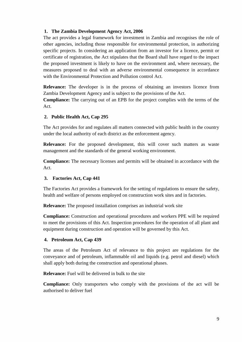
1. The Zambia Development Agency Act, 2006
The act provides a legal framework for investment in Zambia and recognises the role of
other agencies, including those responsible for environmental protection, in authorizing
specific projects. In considering an application from an investor for a licence, permit or
certificate of registration, the Act stipulates that the Board shall have regard to the impact
the proposed investment is likely to have on the environment and, where necessary, the
measures proposed to deal with an adverse environmental consequence in accordance
with the Environmental Protection and Pollution control Act.
Relevance: The developer is in the process of obtaining an investors licence from
Zambia Development Agency and is subject to the provisions of the Act.
Compliance: The carrying out of an EPB for the project complies with the terms of the
Act.
2. Public Health Act, Cap 295
The Act provides for and regulates all matters connected with public health in the country
under the local authority of each district as the enforcement agency.
Relevance: For the proposed development, this will cover such matters as waste
management and the standards of the general working environment.
Compliance: The necessary licenses and permits will be obtained in accordance with the
Act.
3. Factories Act, Cap 441
The Factories Act provides a framework for the setting of regulations to ensure the safety,
health and welfare of persons employed on construction work sites and in factories.
Relevance: The proposed installation comprises an industrial work site
Compliance: Construction and operational procedures and workers PPE will be required
to meet the provisions of this Act. Inspection procedures for the operation of all plant and
equipment during construction and operation will be governed by this Act.
4. Petroleum Act, Cap 439
The areas of the Petroleum Act of relevance to this project are regulations for the
conveyance and of petroleum, inflammable oil and liquids (e.g. petrol and diesel) which
shall apply both during the construction and operational phases.
Relevance: Fuel will be delivered in bulk to the site
Compliance: Only transporters who comply with the provisions of the act will be
authorised to deliver fuel

10
5. Energy Regulation Act, Cap 436
This Act allows for the establishment of procedures for the transportation, handling and
storage fuels to minimise negative environmental impacts.
Relevance: The power generation plant includes a bulk fuel storage installation
Compliance: the design, construction and operation of the plant will comply with the
standards of the Act.
6. Local Government Act, Cap 281
The Act was enacted in 1991 following the repeal of the Local Administration Act of
1981 which incorporated the One Party State political party organs in the local
government system. It provides for the functions of local authorities including the
implementation of environmental protection and natural resources management functions.
Relevance: Implementation and operation of the new development is subject to the
procedures laid out by the local authority (LCC).
Compliance: All applicable by-laws will be adhered to.
7. Town and Country Planning Act, Cap 283
This Act, which came into force in 1962, provides for the establishment of planning
authorities and the preparation, approval and revocation of development plans. It further
provides for the control of development in a district and the subdivision of land.
Relevance: As a new project, the development cannot proceed without town and country
planning approval from the local authority.
Compliance: The necessary documentation has been submitted to LCC and approvals
will be obtained for project implementation in accordance with the terms of the Ac (see
application for planning permission, Appendix 2).
8. Road and Traffic Control Act, Cap 464
The Roads and Traffic Control Act provides for the control of traffic and for the
regulation of storm water disposal structures.
Relevance: The project will involve the construction of an internal road network and
access road to the site subject to the provisions of the Act.
Compliance: The proposed development, roads, and associated infrastructure will be
designed in accordance with the provisions of this act.
11
3.0 Description of the Site and Existing Environment
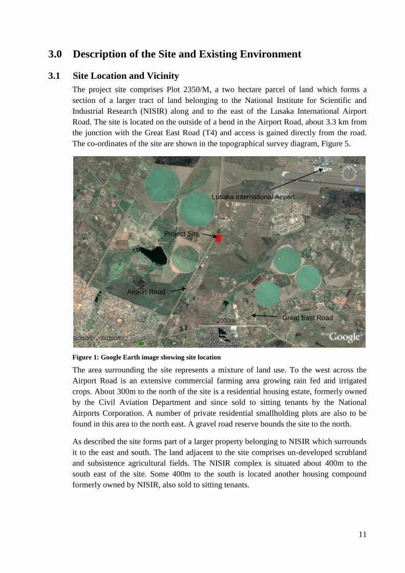
3.1 Site Location and Vicinity
The project site comprises Plot 2350/M, a two hectare parcel of land which forms a
section of a larger tract of land belonging to the National Institute for Scientific and
Industrial Research (NISIR) along and to the east of the Lusaka International Airport
Road. The site is located on the outside of a bend in the Airport Road, about 3.3 km from
the junction with the Great East Road (T4) and access is gained directly from the road.
The co-ordinates of the site are shown in the topographical survey diagram, Figure 5.
Figure 1: Google Earth image showing site location
The area surrounding the site represents a mixture of land use. To the west across the
Airport Road is an extensive commercial farming area growing rain fed and irrigated
crops. About 300m to the north of the site is a residential housing estate, formerly owned
by the Civil Aviation Department and since sold to sitting tenants by the National
Airports Corporation. A number of private residential smallholding plots are also to be
found in this area to the north east. A gravel road reserve bounds the site to the north.
As described the site forms part of a larger property belonging to NISIR which surrounds
it to the east and south. The land adjacent to the site comprises un-developed scrubland
and subsistence agricultural fields. The NISIR complex is situated about 400m to the
south east of the site. Some 400m to the south is located another housing compound
formerly owned by NISIR, also sold to sitting tenants.
Project Site
Airport Road
Great East Road
Lusaka International Airport

12
Figure 2: Google Earth image showing site vicinity
Commercial Agricultural Land
Project Site
Residential Housing and Plots
Residential Housing
NISIR Complex
Airport Road

13
Figure 3: Google Earth image of the site (approximate boundaries)
Airport Road
Gravel Road
14
3.2 Land Ownership and Tenure
The ownership of Plot No. 2350/M is vested in the interest of NISIR under statutory
leasehold. The property will be leased to the developer under agreement with NISIR for
the purposes of the project (please see copy of letter from NISIR to the ECZ, dated 1st
November 2010, included in Appendix 3).
3.3 Existing Physical Developments and Infrastructure
Existing developments surrounding the project site were discussed above. The project
land in question is currently completely undeveloped and represents a Greenfield site. As
described, the site is bounded by the International Airport Road to the west and a gravel
road reserve to the north. In addition:
An 11 kV ZESCO power line runs adjacent to the site within the Airport Road
reserve.
A Lusaka Water and Sewerage Company water main (8”) runs along the Airport
Road to the International Airport.
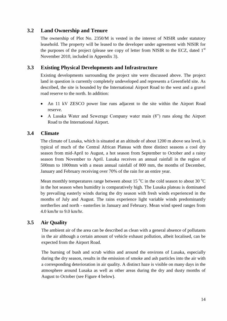
3.4 Climate
The climate of Lusaka, which is situated at an altitude of about 1200 m above sea level, is
typical of much of the Central African Plateau with three distinct seasons a cool dry
season from mid-April to August, a hot season from September to October and a rainy
season from November to April. Lusaka receives an annual rainfall in the region of
500mm to 1000mm with a mean annual rainfall of 800 mm, the months of December,
January and February receiving over 70% of the rain for an entire year.
Mean monthly temperatures range between about 15 oC in the cold season to about 30
oC
in the hot season when humidity is comparatively high. The Lusaka plateau is dominated
by prevailing easterly winds during the dry season with fresh winds experienced in the
months of July and August. The rains experience light variable winds predominantly
northerlies and north - easterlies in January and February. Mean wind speed ranges from
4.0 km/hr to 9.0 km/hr.
3.5 Air Quality
The ambient air of the area can be described as clean with a general absence of pollutants
in the air although a certain amount of vehicle exhaust pollution, albeit localised, can be
expected from the Airport Road.
The burning of bush and scrub within and around the environs of Lusaka, especially
during the dry season, results in the emission of smoke and ash particles into the air with
a corresponding deterioration in air quality. A distinct haze is visible on many days in the
atmosphere around Lusaka as well as other areas during the dry and dusty months of
August to October (see Figure 4 below).

15
Figure 4: Average number of days with smoke/haze in Lusaka (Source:
weatherbase.com)
3.6 Topography
The site is located in a relatively low lying area about 1170m above mean sea level.
Gradients in the area are very low, sloping slightly to the northeast, and the terrain
appears flat to the human eye excepting a few low termite mounds scattered about the
site. A topographical survey diagram of the site is shown in Figure 5 below.
3.7 Geology and Soils
The rocks of the Lusaka area are generally characterised metamorphic rocks of Pre-
Cambrian age belonging to the Katangan system although the site is underlain by more
recent alluvium and thick colluvial deposits of the Chongwe River basin.
Geotechnical investigations were carried out at the site in September 2010 and a copy of
the full report is attached in Appendix 4. Field tests included 7 core borings drilled on the
site in areas were various buildings are proposed. Bedrock was struck at an average depth
of 20m and test results indicated that the bedrock consisted generally of a sheared
Quartzite that appeared as quartz-sericite schist in some of the holes. However, in B7, B9
and B10, the fine grained quartzite was less deformed, but was generally fractured.
A number of trial pits were also dug and grading analyses performed on soil samples, all
samples taken exhibited fine grained texture. In accordance with the Unified
Classification chart, the soils may be classified as CL-Inorganic Clays of low plasticity as
the Liquid Limits were less than 35.
0
5
10
15
20
25
30
Jan Feb Mar Apr May Jun Jul Aug Sep Oct Nov Dec
No
. D
ays
Month
Average No. Days with Smoke/Haze (Years on record: 15)
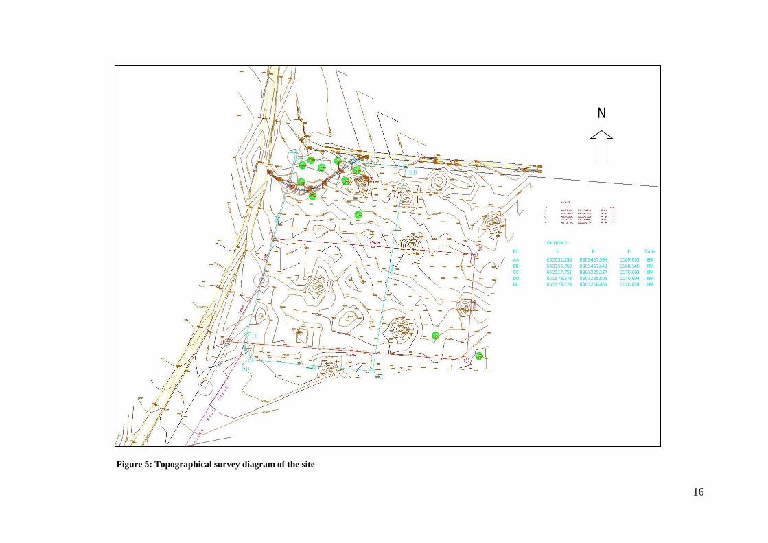
16
Figure 5: Topographical survey diagram of the site
N

17
3.7.1 Soil Quality
In order to form a baseline of potential soil contaminants prior to project implementation,
soil samples were taken from the site and analyzed for their heavy metal characteristics.
Samples were taken from two borings at depths of 3, 6, and 9m and analytes determined
by use of Atomic Absorption Spectrophotometry. Metal analytes tested were: Copper,
Zinc, Cadmium, Lead, Chromium, Nickel, Iron, Cobalt, and Mercury, and the full
laboratory test results are given in Appendix 5. Results show that for the samples taken
all heavy metal levels are substantially below the maximum permissible levels for soil
and water.
3.8 Hydrology
3.8.1 Surface Water
No natural streams or water courses traverse the project site; however, a storm water
drain emanating from a culvert under the Airport Road traverses the northwestern corner
of the site (see topographical survey diagram, Figure 5). This drain discharges into the
stormwater drainage system of the gravel road that runs along the northern boundary of
the site, carrying water away from the Airport Road in an easterly direction (i.e. down
slope).
Most of the site appears well drained although it is apparent that water logging may occur
in the northwestern corner during the rains.
3.8.2 Hydrogeology
Under geotechnical investigations (Appendix 4), the core borings revealed the presence
of a large ‘Fissure’ or ‘Cavity’ that was in-filled with unconsolidated sand that
immediately overlies the bedrock (the bedrock was intersected between 17.5 to 22.5m
depth). It is suspected that the cavity may be acting as an aquifer.
Core borings at the proposed site indicated that the water table was at 1.5 to 2.0m level,
in most cases. This level would be expected to rise closer to the surface during the course
of the rainy season.
3.9 Flora / Fauna
The area comprises a scrubland previously cleared, probably for agricultural purposes,
and is characterized by juvenile or coppiced re-growth of trees and shrubs scattered or
grouped about the site. The species noted are typical of the Munga (Savanna) Woodland
type of vegetation that is found in the area and common around Lusaka. Dominant
species include Pilostigma thonningii (msekese) and Acacia polyacantha (hook thorn).
Two or three medium sized Ficus sycomorus (mukuyu) are conspicuous near the
northern boundary of the site, and a stand of relatively mature trees (hookthorn and
msekese) is grouped in the north-western corner. Other species noted, also common to
the type of vegetation in the area were Acacia siberana (White Thorn), Strychnos
18
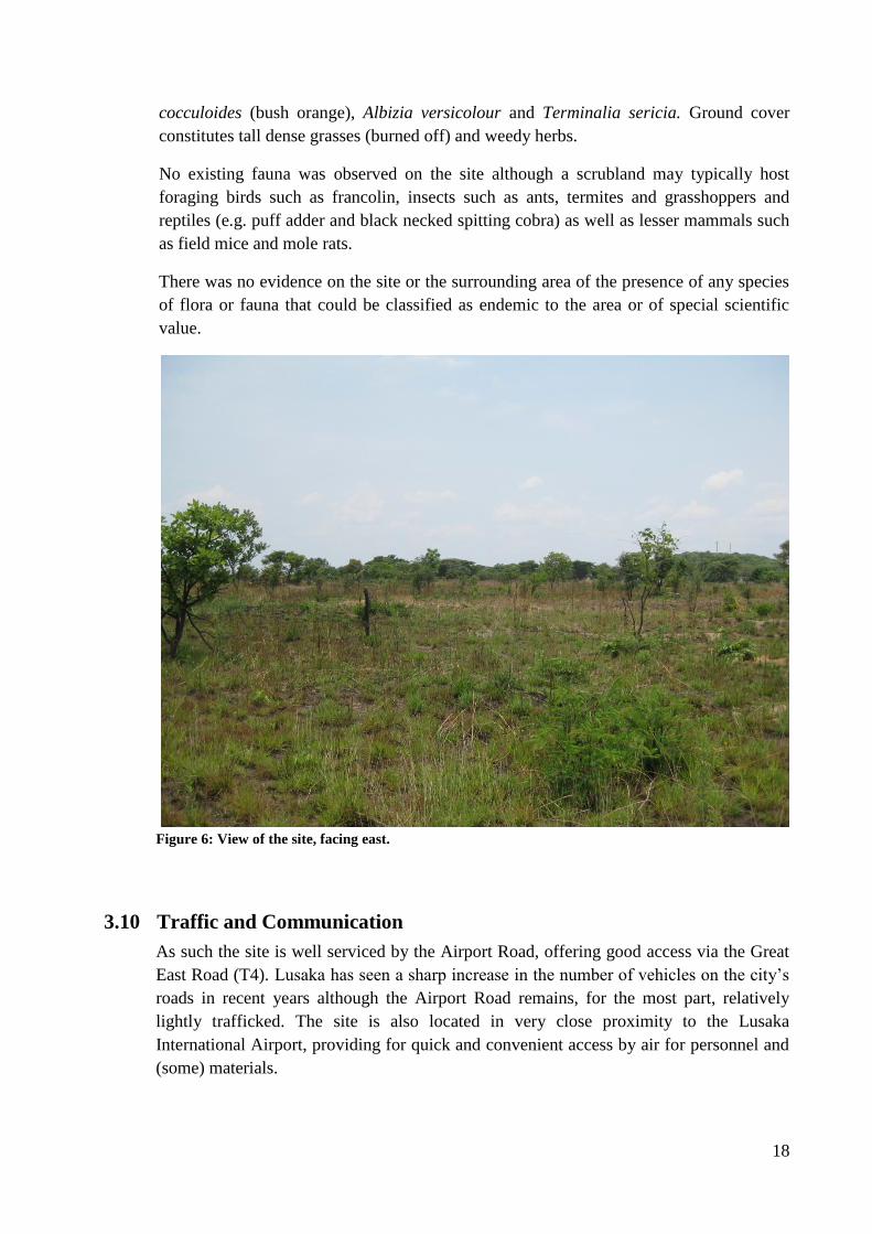
cocculoides (bush orange), Albizia versicolour and Terminalia sericia. Ground cover
constitutes tall dense grasses (burned off) and weedy herbs.
No existing fauna was observed on the site although a scrubland may typically host
foraging birds such as francolin, insects such as ants, termites and grasshoppers and
reptiles (e.g. puff adder and black necked spitting cobra) as well as lesser mammals such
as field mice and mole rats.
There was no evidence on the site or the surrounding area of the presence of any species
of flora or fauna that could be classified as endemic to the area or of special scientific
value.
Figure 6: View of the site, facing east.
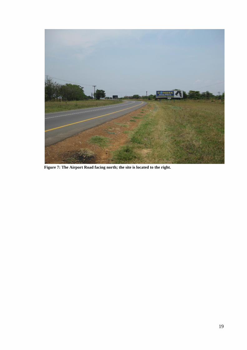
3.10 Traffic and Communication
As such the site is well serviced by the Airport Road, offering good access via the Great
East Road (T4). Lusaka has seen a sharp increase in the number of vehicles on the city’s
roads in recent years although the Airport Road remains, for the most part, relatively
lightly trafficked. The site is also located in very close proximity to the Lusaka
International Airport, providing for quick and convenient access by air for personnel and
(some) materials.
19
Figure 7: The Airport Road facing north; the site is located to the right.

20
4.0 Description of the Project
4.1 Objectives and Nature of the Project
The proposed project calls for the construction and operation of a Remanufacturing
(‘Reman’) Factory on Plot No. 2350/M along the Lusaka International Airport Road. The
nature of the principle business to be carried out at the site will be the remanufacturing
(or reconditioning) of machine parts for large scale earth moving equipment for
industries, especially the mining sector, within and outside Zambia. This will involve the
re-manufacture of used parts and components of earth moving machineries so as to
provide more economical solutions by supplying remanufactured components to
customers at more economical prices.
The development will also serve as the headquarters for HCMZ’s operations and
activities in Zambia and adjacent countries which includes the sales of machineries and
parts as well as service and maintenance of earthmoving equipment.
For this purpose the project will entail the construction of a workshop, a warehouse and a
main office building covering a footprint of 3,911.5m2 and with a gross floor area of
4,480.9m2. A provision of 2,520m
2 floor area will be made for future expansion of the
workshop and warehouse.
A reputable Zambian registered contractor will have overall construction responsibility
for the project and will be required to work closely with local (and where necessary
foreign specialised) contractors and sub-contractors to complete the works.
Construction of the factory scheduled to commence 4th
Quarter 2010, with a eight month
construction cycle and commissioning and hand-over scheduled for 3rd
Quarter 2011.
Capacity building will form a principle component of the Company’s activities at the site
during operation and the development will include the required training facilities.
Training will be provided on-the-job for permanent employees and the Company is also
committed to providing industrial internships on a continuous basis for students from the
Country’s various technical colleges (e.g. Nortech).
It is anticipated that the remanufacturing plant will provide permanent employment for 30
skilled Zambian workers.
4.2 Physical and Technical Aspects of the Project
The various project layout and design drawings are given in Appendix 6 as follows:
1027-A-06: Site Plan
1027-A-07: Ground Floor Plans
1027-A-08: 1st Floor Plans
1027-A-09: Roof Plans
1027-A-10: Elevations
21
1027-A-11: Sections
1027-A-15: External Works
The development will include the following major components:
4.2.1 Buildings
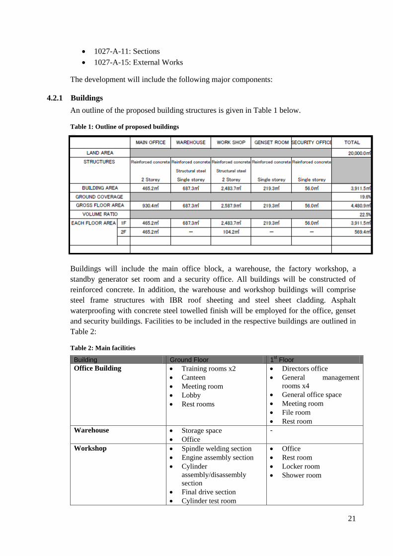
An outline of the proposed building structures is given in Table 1 below.
Table 1: Outline of proposed buildings
Buildings will include the main office block, a warehouse, the factory workshop, a
standby generator set room and a security office. All buildings will be constructed of
reinforced concrete. In addition, the warehouse and workshop buildings will comprise
steel frame structures with IBR roof sheeting and steel sheet cladding. Asphalt
waterproofing with concrete steel towelled finish will be employed for the office, genset
and security buildings. Facilities to be included in the respective buildings are outlined in
Table 2:
Table 2: Main facilities
Building Ground Floor 1st Floor
Office Building Training rooms x2
Canteen
Meeting room
Lobby
Rest rooms
Directors office
General management
rooms x4
General office space
Meeting room
File room
Rest room
Warehouse Storage space
Office
-
Workshop Spindle welding section
Engine assembly section
Cylinder
assembly/disassembly
section
Final drive section
Cylinder test room
Office
Rest room
Locker room
Shower room
22
Pump motor test room
Pump motor assembly
room
Engine cleaning room
Engine dynamo room
Painting room
Drying room
Tool room
Compressor room
Oil storage room
Rest room
Genset Generator plant room
Fuel tank room
Trance room
Panel room
-
Security Security office room -
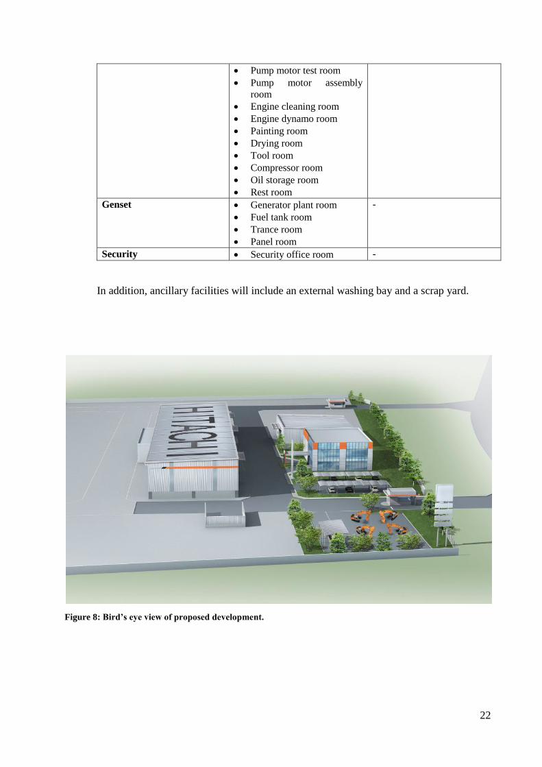
In addition, ancillary facilities will include an external washing bay and a scrap yard.
Figure 8: Bird’s eye view of proposed development.
23
4.2.2 Services
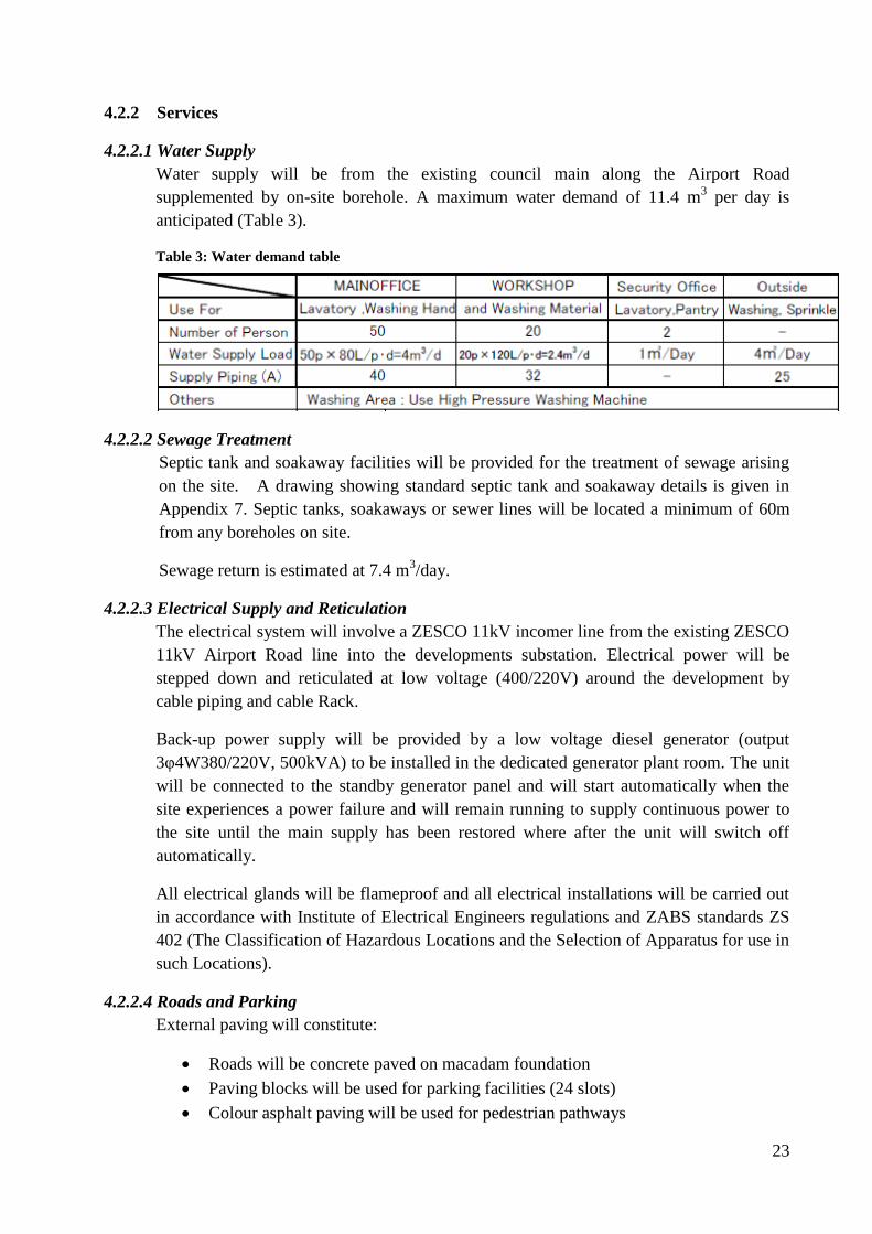
4.2.2.1 Water Supply
Water supply will be from the existing council main along the Airport Road
supplemented by on-site borehole. A maximum water demand of 11.4 m3 per day is
anticipated (Table 3).
Table 3: Water demand table
4.2.2.2 Sewage Treatment
Septic tank and soakaway facilities will be provided for the treatment of sewage arising
on the site. A drawing showing standard septic tank and soakaway details is given in
Appendix 7. Septic tanks, soakaways or sewer lines will be located a minimum of 60m
from any boreholes on site.
Sewage return is estimated at 7.4 m3/day.
4.2.2.3 Electrical Supply and Reticulation
The electrical system will involve a ZESCO 11kV incomer line from the existing ZESCO
11kV Airport Road line into the developments substation. Electrical power will be
stepped down and reticulated at low voltage (400/220V) around the development by
cable piping and cable Rack.
Back-up power supply will be provided by a low voltage diesel generator (output
3φ4W380/220V, 500kVA) to be installed in the dedicated generator plant room. The unit
will be connected to the standby generator panel and will start automatically when the
site experiences a power failure and will remain running to supply continuous power to
the site until the main supply has been restored where after the unit will switch off
automatically.
All electrical glands will be flameproof and all electrical installations will be carried out
in accordance with Institute of Electrical Engineers regulations and ZABS standards ZS
402 (The Classification of Hazardous Locations and the Selection of Apparatus for use in
such Locations).
4.2.2.4 Roads and Parking
External paving will constitute:
Roads will be concrete paved on macadam foundation
Paving blocks will be used for parking facilities (24 slots)
Colour asphalt paving will be used for pedestrian pathways

24
4.2.2.5 Storm Water
Storm water drainage will be by closed lined drains (covered by grating or concrete slab)
to both the front and rear of the site and will tie into an open lined perimeter drain
surrounding the boundary of the site. This will discharge to the existing drainage system
in the road reserve along the northern boundary of the site via an oil separator. Waste
water from the external washing bay and engine washing room in the workshop will be
directed through dedicated oil interceptors prior to discharge to the storm water drainage
system.
4.2.2.6 Bulk Fuel Storage
Bulk fuel storage will be provided in accordance with Energy Regulation Board
regulations and the standards set by The Zambian Bureau of Standards: ZS 392: Part 2
(Zambian Standards for The Storage and Handling of Liquid Fuels: For large consumer
installations exceeding 1,500 litres in the case of a liquid fuel having a flash point not
lower than 38oC).
Bulk storage of diesel will be provided by two 5,000 litre above ground fuel storage tanks
(i.e. a total of 10,000 litres) for the generator and for forklift trucks/machinery testing
respectively.
In line with ZABS standards, the tanks and pipe work will be constructed within concrete
containment bunds with a reinforced concrete slab and solid concrete block walls to
prevent any egress of hydrocarbon fuels and/or lubricants outside the bund and thus to
ground.
Each containment bund will have a capacity equivalent to 110% of the volume of the
largest tank installed within it. All bunds will have a drainage sump with a valve fitted to
the outside of the bund and a piped drain to a common oil interceptor constructed in
accordance with the calculated flows of storm water anticipated. This valve will enable
normal flow off the bund during wash downs and rain into the oil interceptor. However,
in the event of a major leak/spill the valve can be closed to contain the fuels for pumping
out into another tank or vehicle. In addition, the entire generator plant room floor and one
brick height (110mm) of the wall will be painted with diesel resistant epoxy paint and
will be utilized as a bund wall for the generator. This bund will also have a drainage
sump with a valve fitted to the outside of the bund and a piped drain to the oil
interceptor.
The off-loading pump, fuel filters and supply and return feeds will also be located within
the same bund in order to prevent any fuel or lubricant leaks to ground due to pipe leaks
or pump seal failure.
The loading / off loading point to and from vehicles will comprise a hard standing
surface with drainage to the oil interceptor.
25
A drawing showing standard installation layout and details for a 5,000 litre above ground
steel skid tank is given in Appendix 8. A detailed drawing of the oil interceptor is given
in Appendix 9.
The above measures will ensure that there are no fuel spills or leaks to ground during the
operation of the fuel storage facility and generator sets and any major leaks can be
contained and thus treated in a safe and acceptable manner to all regulatory authorities.
4.2.2.7 Workshop Utility Works
This will include:
Compressed-Air System
Cooling Water Supply System (for Engine Cooling)
Exhaust System for Production
Drainage Water System for production
High Pressure Washing
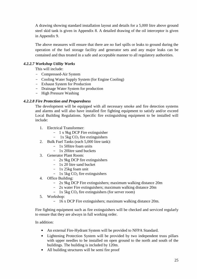
4.2.2.8 Fire Protection and Preparedness
The development will be equipped with all necessary smoke and fire detection systems
and alarms and will also have installed fire fighting equipment to satisfy and/or exceed
Local Building Regulations. Specific fire extinguishing equipment to be installed will
include:
1. Electrical Transformer:
1 x 9kg DCP Fire extinguisher
1x 5kg CO2 fire extinguishers
2. Bulk Fuel Tanks (each 5,000 litre tank):
1x 50litre foam units
1x 20litre sand buckets
3. Generator Plant Room:
2x 9kg DCP fire extinguishers
1x 20 litre sand bucket
1x 25kg foam unit
1x 5kg CO2 fire extinguishers
4. Office Building:
2x 9kg DCP Fire extinguishers; maximum walking distance 20m
2x water Fire extinguishers; maximum walking distance 20m
1x 5kg CO2 fire extinguishers (for server room)
5. Workshop:
16 x DCP Fire extinguishers; maximum walking distance 20m.
Fire fighting equipment such as fire extinguishers will be checked and serviced regularly
to ensure that they are always in full working order.
In addition:
• An external Fire-Hydrant System will be provided to NFPA Standard.
• Lightening Protection System will be provided by two independent truss pillars
with upper needles to be installed on open ground to the north and south of the
buildings. The building is included by 120m.
• All building structures will be semi fire proof
26
• As described, all electrical glands will be flameproof and all electrical
installations will be carried out in accordance with Institute of Electrical
Engineers regulations and ZABS standards ZS 402.
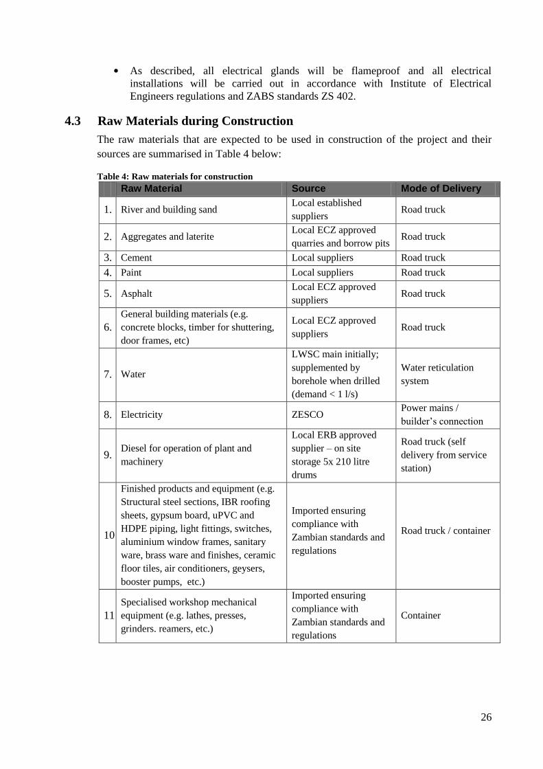
4.3 Raw Materials during Construction
The raw materials that are expected to be used in construction of the project and their
sources are summarised in Table 4 below:
Table 4: Raw materials for construction
Raw Material Source Mode of Delivery
1. River and building sand Local established
suppliers Road truck
2. Aggregates and laterite Local ECZ approved
quarries and borrow pits Road truck
3. Cement Local suppliers Road truck
4. Paint Local suppliers Road truck
5. Asphalt Local ECZ approved
suppliers Road truck
6.
General building materials (e.g.
concrete blocks, timber for shuttering,
door frames, etc)
Local ECZ approved
suppliers Road truck
7. Water
LWSC main initially;
supplemented by
borehole when drilled
(demand < 1 l/s)
Water reticulation
system
8. Electricity ZESCO Power mains /
builder’s connection
9. Diesel for operation of plant and
machinery
Local ERB approved
supplier – on site
storage 5x 210 litre
drums
Road truck (self
delivery from service
station)
10.
Finished products and equipment (e.g.
Structural steel sections, IBR roofing
sheets, gypsum board, uPVC and
HDPE piping, light fittings, switches,
aluminium window frames, sanitary
ware, brass ware and finishes, ceramic
floor tiles, air conditioners, geysers,
booster pumps, etc.)
Imported ensuring
compliance with
Zambian standards and
regulations
Road truck / container
11.
Specialised workshop mechanical
equipment (e.g. lathes, presses,
grinders. reamers, etc.)
Imported ensuring
compliance with
Zambian standards and
regulations
Container
27
4.4 Activities during Construction
The main activities envisaged during construction will include:
1. Preparation of the site. This will include:
Stripping of topsoil and vegetative material
Basic earthworks to establish required finished levels and falls. This will entail
filling of areas with laterite and aggregates.
Drilling and equipping of on-site borehole
2. Excavation and foundations:
Piling to create sub-structure foundation supports
Excavation of trenches for foundation strips, oil interceptors, soak-aways etc.
Compaction of underside of foundation trenches
Mixing, pouring and compaction of concrete
3. Sub-structural works and floor slab:
Block work
Mixing, pouring and compaction of concrete
Backfilling and compaction of material according to specifications
4. Super-structural works:
Construction of various buildings including placing of hollow concrete blocks,
fixing of structural steel components, fixing of roofing sheets and cladding, etc.
5. Road and drainage construction:
Stabilization of the base with the piling, spreading and compaction of gravel and
aggregate.
Spreading and compaction of aggregates and tar materials on the road for
bitumen surface and preparation, pouring and compaction of concrete for
concrete surfaced areas.
Excavation and shaping of drains
6. Installation of mechanical equipment / engineering services:
This will involve installation of the mechanical equipment for the factory
workshop and installation of electric power supply, cables, lighting, etc.
7. Materials Storage
Materials such as blocks, sand, gravel and aggregate, which are not required for
immediate use, may be stockpiled in limited quantities in a designated area on the
site.
4.5 Waste Products during Construction
The following waste and by-products are expected to be generated during the project
construction cycle:
• Vegetative waste: A limited amount of vegetative waste, mainly small trees and
shrubs will be generated from site preparation.
• Topsoil: Topsoil resulting from scarifying of the site.
• Building rubble: This will include sub-soil removed during excavation of trenches /
drains and other spoil such as rejected concrete, broken blocks and tiles, etc.

28
• Solid waste: other solid construction waste will include material such as scrap timber
and various off cuts and refuse such as discarded packaging (e.g. plastic, cement
bags), workers garbage and domestic waste from workers canteen etc.
• Hazardous waste: A small amount of hazardous waste is expected to result from
construction activities; this will comprise mainly of empty paint and chemical (e.g.
termidan) containers.
• Sewage: Sanitary waste generated by the construction workforce.
• Runoff: Stormwater runoff from the site
• Dust: Dust will be generated on the site from delivery of material and various
construction activities.
• Exhaust emissions: from operation of vehicles and machinery on site.
4.6 Raw Materials during Operation
The primary raw materials during operation will be:
Table 5: Raw materials for operation
Raw Material Purpose Source
1. Water; maximum demand 11.4 m
3 per
day
Ablution and
sanitary
Washing of
machinery and parts
Irrigation
Fire water
LWSC main and on-
site borehole
2. Electricity
Powering of
mechanical
equipment
Lighting, air
conditioning, etc
11 kV ZESCO main
3. Diesel fuel; on-site storage 2x 5,000
litre
Generator set
Vehicles (forklift
and truck)
Local ERB approved
supplier
4. Coolants
Generator set
Vehicles (forklift
and truck)
Local ERB approved
supplier
5. Lubricants
Generator set
Vehicles (forklift
and truck)
Test stand
Hydraulic
components
Lathe
Painting booth
Local ERB approved
supplier
29
Raw Material Purpose Source
6. Kerosene Washing bay Local ERB approved
supplier
7. Oxygen and Acetylene gas Welding Local ERB approved
supplier
8. Paints and thinners Paint booth
Local supplier or
Imported ensuring
compliance with
Zambian standards and
regulations
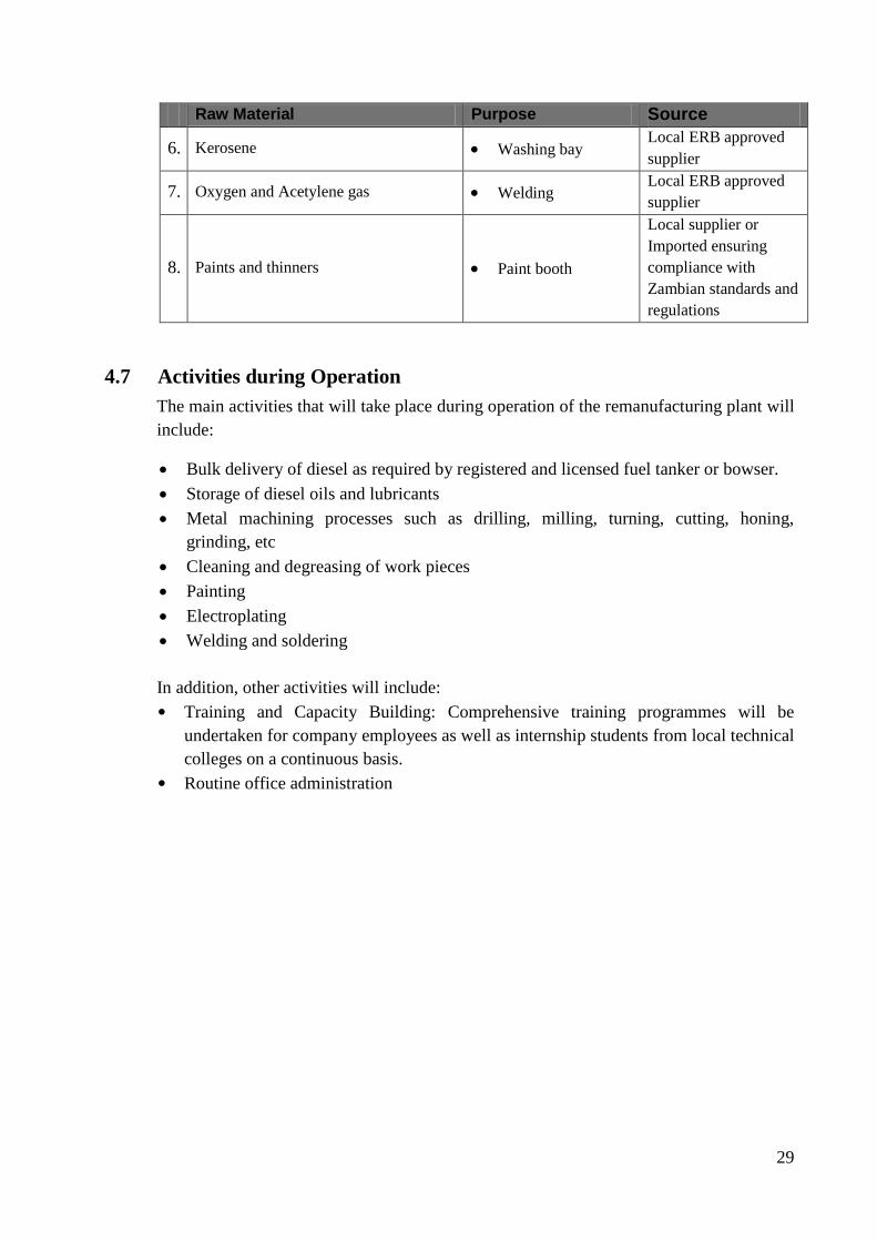
4.7 Activities during Operation
The main activities that will take place during operation of the remanufacturing plant will
include:
Bulk delivery of diesel as required by registered and licensed fuel tanker or bowser.
Storage of diesel oils and lubricants
Metal machining processes such as drilling, milling, turning, cutting, honing,
grinding, etc
Cleaning and degreasing of work pieces
Painting
Electroplating
Welding and soldering
In addition, other activities will include:
• Training and Capacity Building: Comprehensive training programmes will be
undertaken for company employees as well as internship students from local technical
colleges on a continuous basis.
• Routine office administration
30
4.8 Waste and By-products during Operation
Waste and by-products resulting from various activities during operation will include:
• Sewage: From ablution and sanitary facilities; sewage return estimated at 7.4 m3/day.
• Waste water:
Storm water from the fuel storage area(s) and out door paved areas may contain some
hydrocarbons minor leaks occurring from vehicles, pump seals, etc. or due to spillage
during offloading.
Waste water will be generated from the external and internal washing bays which will
contain oils and lubricants
• Used oil and Lubricants/coolants: From machinery under repair and workshop
mechanical equipment
• Metal Chafing: this includes metal chafing, dust and shavings from various
machining processes such as drilling, milling, turning, cutting, honing, grinding etc.
• Scrap metal: Damaged and rejected used parts and components
• Emissions:
Aerosols may be produced from various machining processes using lubricants and
coolants
Aerosols will result from painting operations
Some exhaust emissions will result from the operation of diesel combustion engines
(forklifts, generator set)
• Waste paper: Paper towels and waste paper (very limited) from the office
31
5.0 Project Alternatives
5.1 Site Location
The proposed site was identified as being suitable and allocated to the developer for the
purposes of the project by the Zambian Government through the Zambia development
Agency and Ministry of Science and Technology. As such, alternative sites have not been
considered by the developer. Advantages of the proposed site include:
• The site is centrally and strategically located in Zambia to service the Company’s
operations on the Copperbelt and Mozambique, and in future Angola, Botswana and
Zimbabwe.
• The site offers excellent access by road as well as by air.
• The site is well serviced by other existing infrastructural services including water and
electricity mains.
• The site has good ground water potential
• The flat terrain of the site is suitable for the project
• The site represents a prominent position offering very good visibility and exposure
for the company. This is deemed an important factor to ensure the success of the
Company’s future expansion plans within the Country and the region, and to promote
the Company’s capacity building programmes.
5.2 Building Construction
In terms of raw construction materials, technologies most suitable for the local climate
and conditions have been adopted for construction of the buildings i.e. concrete block,
reinforced concrete, structural steel and metal roof cladding and sheeting.
5.3 Raw Materials and Process Technology
In terms of operation, Hitachi Construction Machinery have standard equipment and
processes developed over many years to ensure the best efficiency, sustainability and
operation of their workshops. Thus the technologies to be employed comply with Hitachi
worldwide standards.

32
6.0 Assessment of Environmental Impacts
6.1 Positive Impacts
A number of important benefits and advantages are expected to result from
implementation of the project:
• The establishment of the Reman plant will allow for the supply of high quality
reconditioned parts and components at a far more economical cost than the
importation of new components. This will reduce maintenance costs and provide an
economic boost to industrial sectors employing heavy duty earth moving machinery.
• The establishment of the development as HCMZ’s strategic headquarters in Lusaka
will help the company to consolidate its operations in Zambia and the region. This
will contribute to promoting Zambia as a prime regional hub for business in Southern
Africa.
• The new plant will provide direct permanent employment opportunities for up to 30
skilled Zambian personnel which will be a welcome development for the local labour
market.
• The new project and multiplier effects such as increased employment and increased
investment in the industrial and mining sectors will result in increased public
revenues such as taxes (PAYE, VAT, corporate tax) to ZRA, increased revenue to the
council in terms of rates and increased contributions to NAPSA from formally
employed persons.
• Capacity building and technology transfer: Training will be provided on-the-job for
permanent employees and as a part of HCMZ’s corporate social responsibility the
Company is also committed to providing industrial internships on a continuous basis
for students from the Country’s various technical colleges (e.g. Nortech).
6.2 Negative Impacts during Construction
6.2.1 Impacts on Air Quality and Noise Environment
Due to the nature of construction processes, it is expected that there will be a general
increase in dust and noise pollution on the site resulting from the use of heavy machinery
during earthworks, the delivery and offloading of materials, use of compressors and
compactors, etc. Dust may be raised from exposed worksites and surfaces especially
during windy conditions. However, there are no immediate neighbouring residential areas
or other developments surrounding the site, and the area down wind of the site (to the
west) comprises open agricultural land. Therefore dust raised will pose mostly a nuisance
to construction workers, although effects are expected to be intermittent. In addition, the
access road to the project area is paved all the way to the site and therefore dust raised by
construction traffic travelling to and from the site is expected to be insignificant.
6.2.2 Impacts on Surface and Ground Water
Preparation of the site and construction is not expected to affect any existing natural
drainage courses and gradients on the site are very flat so there is limited risk of soil
erosion occurring during earthworks which could result in siltation and contamination of

33
down stream drainage features. However there is the potential for blocking the existing
storm drain structure that currently traverses the north-western corner of the site. This in
turn could result in the flooding of the Airport Road reserve.
Potential sources of soil and ground water (as well as surface water) contamination on the
site, especially during periods of rainfall, include improper facilities for fuel storage and
dispensing, leakages of oil and hydraulic fluids from badly maintained machinery,
building waste and garbage and improper sanitary facilities for workers.
6.2.3 Impacts on Vegetation and Habitat
It is expected that most existing vegetation on the site will be removed for the purposes of
site preparation and construction. However, as the site has previously been cleared and
hosts largely scrub vegetation, the impact of loss of vegetation and habitat is considered
insignificant. In addition, as no evidence of flora or fauna which is rare or of scientific
value was found on the site, the project will not impact on biological diversity.
6.2.4 Impacts on Traffic and Road Safety
As a medium scale construction works, the project will involve a certain amount of
construction traffic travelling to and from the site; however it is expected that any
significant traffic will occur in phases such as during the haulage and delivery of
materials. As the main contractor will be largely self-contained on site traffic is generally
expected to be limited to light vehicles, including sub-contractors vehicles and workers’
transportation. In addition the Airport Road is at present moderately trafficked, therefore,
additional impacts on general traffic congestion or road safety in the project vicinity are
considered to be moderate to low.
6.2.5 Impacts on Occupational Health and Safety
Although the scope of works is relatively small, construction will involve activities and
procedures with potentially high risk levels to the occupational health and safety of
workers and personnel. These include:
Movement of construction traffic and machinery around the site
Working in confined spaces (e.g. trenches)
Work with open flames (e.g. welding) and cutting operations
Work in dusty environment
Work at height (e.g. scaffolding and roofs)
Strict adherence to safety measures and procedures will minimise (or eliminate) risks of
accidents or hazardous developments occurring.
6.2.6. Impacts on Public Health and Safety
During construction, there is the potential for accidents occurring involving members of
the public who may inadvertently gain access to the project site, although the site is
located some distance away from any significant settlement.
34
Potential contamination of water resources, as discussed above, can be of public health
concern; however the project is relatively small in scope. The project will not employ a
large migratory workforce and social and epidemiological factors commonly associated
with this will not be relevant.
6.3 Negative Impacts during Operation
6.3.1 Impacts on Noise Environment
During operation it is not expected that any activities of the project will produce noise
levels beyond the confines of the remanufacturing factory that will be of a nuisance to
neighbours. In addition surrounding residential areas will be located a reasonable distance
from the plant, the nearest being some 300m to the north. However, the use of high-speed
mechanical equipment and the intensive use of machines in small spaces can give rise to
potentially hazardous noise levels within the plant.
6.3.2 Impact on Air Quality
The production of aerosols is inherent to some of the activities to be undertaken in the
workshop such as spray painting and various machining processes whereby lubricants
and coolants are used to dose tools and work pieces in order to dissipate heat. Potential
emissions to air outside the plant would be expected to be limited and much localised;
however, implications on operator health and safety can be significant if proper
precautionary measures are not implemented.
6.3.3 Impacts on Soils and Water Quality
There is a potential for surface and ground water pollution occurring due to contaminants
emanating from various waste products generated by activities during operation entering
the surface drainage regime and / or polluting the soil and infiltrating the underlying
aquifer. Principal point and diffused sources of contaminants include:
The storage of petroleum products (diesel) at the new plant presents the risk of
contamination of surface or groundwater if accidental leaks occur in the fuel tanks
and associated works. Fuel spillages from the bulk delivery and dispensing of fuel at
the facility also present the risk of the contamination of surface run-off and
subsequently ground water.
Improper storage and disposal of used oil, coolants and hydraulic fluids from used
machinery under rehabilitation and various machining processes.
Waste water from the out door washing bay and indoor engine washing booth that
will contain oils and greases
Storm water run-off from the internal road and parking areas may contain liquid
waste from accidental oil leaks from vehicles
Improper storage and disposal of other hazardous wastes such as empty paint and
chemical containers
35
Sewage generated during operation if discharged into the aquatic environment
without adequate treatment would result in the contamination of ground or surface
water resources.
Oils and greases contain hydrocarbons and/or heavy metals such as lead, chromium and
cadmium, which are known drinking water pollutants. Negative impacts of this are
potentially significant if specific measures are not taken for on-site waste management.
6.3.4 Impact on Surface Water Flow
As described, the construction of the development will not disrupt any natural surface
drainage courses and permanent drainage structures will be constructed as outlined in
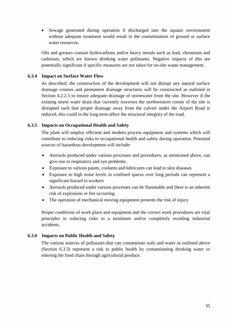
Section 4.2.2.5 to ensure adequate drainage of stormwater from the site. However if the
existing storm water drain that currently traverses the northwestern corner of the site is
disrupted such that proper drainage away from the culvert under the Airport Road is
reduced, this could in the long term affect the structural integrity of the road.
6.3.5 Impacts on Occupational Health and Safety
The plant will employ efficient and modern process equipment and systems which will
contribute to reducing risks to occupational health and safety during operation. Potential
sources of hazardous development will include:
Aerosols produced under various processes and procedures, as mentioned above, can
give rise to respiratory and eye problems.
Exposure to various paints, coolants and lubricants can lead to skin diseases
Exposure to high noise levels in confined spaces over long periods can represent a
significant hazard to workers
Aerosols produced under various processes can be flammable and there is an inherent
risk of explosions or fire occurring.
The operation of mechanical moving equipment presents the risk of injury
Proper conditions of work place and equipment and the correct work procedures are vital
principles in reducing risks to a minimum and/or completely avoiding industrial
accidents.
6.3.6 Impacts on Public Health and Safety
The various sources of pollutants that can contaminate soils and water as outlined above
(Section 6.3.3) represent a risk to public health by contaminating drinking water or
entering the food chain through agricultural produce.

36
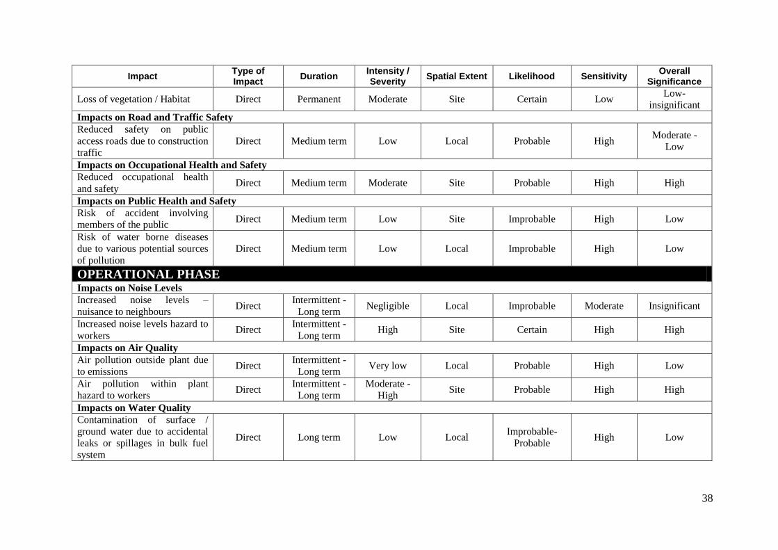
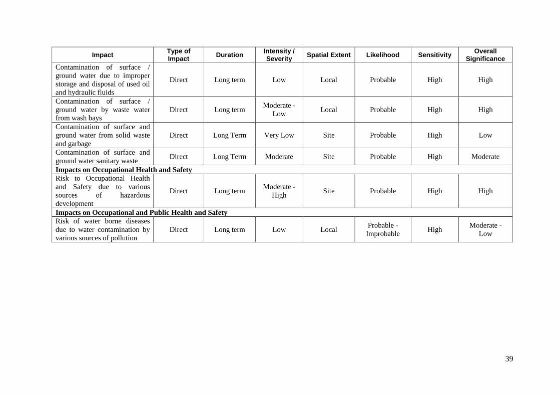
6.4 Evaluation of Potential Impacts
An appraisal of potential negative impacts that may result from the project during the
construction and operational phases was given in the narratives in Sections 6.2 and 6.3
above. An attempt is made in this section to evaluate the overall significance of each
identified impact by assigning values to a set of criteria as follows:
Type of Impact (Direct / Indirect)
Duration (Intermittent / Temporary / Short Term / Medium Term (construction
phase) / Long Term / Permanent)
Intensity / Severity (Negligible / Low / Moderate / High)
Spatial Extent (Site / Local (area surrounding the site) / Regional)
Likelihood (Uncertain / Improbable / Probable / Highly Probable / Certain)
Sensitivity [of the receptor; degree of change effected on natural processes or peoples
livelihoods] (Low / Moderate / High)
Overall Significance (Insignificant / Low / Moderate / High)
The evaluation of impacts using these criteria is presented in Table 6 below:

37
Table 6: Evaluation of impacts
Impact Type of Impact
Duration Intensity / Severity
Spatial Extent Likelihood Sensitivity Overall
Significance
CONSTRUCTION PHASE Impacts on Air Quality and Noise Levels Dust releases due to exposed
work sites – nuisance to
neighbours Direct
Intermittent-
Medium term Low Local Improbable Moderate Insignificant
Dust releases due to exposed
work sites – nuisance to
workers Direct
Intermittent-
Medium term Low Site Probable Moderate
Moderate -
Low
Noise from construction
machinery / traffic Direct
Intermittent –
Medium term Low Site Probable Low Very Low
Impacts on Surface and Ground Water Erosion and siltation of
downstream drainage system Direct Temporary Low Local Improbable Moderate Insignificant
Disruption of surface drainage
regime (NW corner of the site)
and drainage away from the
Airport Road
Direct Medium term Moderate Local Probable High Moderate
Contamination of surface and
ground water due to accidental
oil and fuel spillages and
leakages from transport and
dispensing of petroleum
products and badly maintained
construction machinery
Direct Medium term Low Site Probable High Moderate -
Low
Contamination of run-off and
ground water from solid waste
and garbage Direct Medium term Low Site Probable High Low
Contamination of surface and
ground water by workers
sanitary waste Direct Medium term
Low-
Moderate Site Probable High Moderate
Impacts on Ecosystem
38
Impact Type of Impact
Duration Intensity / Severity
Spatial Extent Likelihood Sensitivity Overall
Significance
Loss of vegetation / Habitat Direct Permanent Moderate Site Certain Low Low-
insignificant Impacts on Road and Traffic Safety Reduced safety on public
access roads due to construction
traffic Direct Medium term Low Local Probable High
Moderate -
Low
Impacts on Occupational Health and Safety Reduced occupational health
and safety Direct Medium term Moderate Site Probable High High
Impacts on Public Health and Safety Risk of accident involving
members of the public Direct Medium term Low Site Improbable High Low
Risk of water borne diseases
due to various potential sources
of pollution Direct Medium term Low Local Improbable High Low
OPERATIONAL PHASE Impacts on Noise Levels Increased noise levels –
nuisance to neighbours Direct
Intermittent -
Long term Negligible Local Improbable Moderate Insignificant
Increased noise levels hazard to
workers Direct
Intermittent -
Long term High Site Certain High High
Impacts on Air Quality Air pollution outside plant due
to emissions Direct
Intermittent -
Long term Very low Local Probable High Low
Air pollution within plant
hazard to workers Direct
Intermittent -
Long term Moderate -
High Site Probable High High
Impacts on Water Quality Contamination of surface /
ground water due to accidental
leaks or spillages in bulk fuel
system
Direct Long term Low Local Improbable-
Probable High Low
39
Impact Type of Impact
Duration Intensity / Severity
Spatial Extent Likelihood Sensitivity Overall
Significance
Contamination of surface /
ground water due to improper
storage and disposal of used oil
and hydraulic fluids
Direct Long term Low Local Probable High High
Contamination of surface /
ground water by waste water
from wash bays Direct Long term
Moderate -
Low Local Probable High High
Contamination of surface and
ground water from solid waste
and garbage Direct Long Term Very Low Site Probable High Low
Contamination of surface and
ground water sanitary waste Direct Long Term Moderate Site Probable High Moderate
Impacts on Occupational Health and Safety Risk to Occupational Health
and Safety due to various
sources of hazardous
development
Direct Long term Moderate -
High Site Probable High High
Impacts on Occupational and Public Health and Safety Risk of water borne diseases
due to water contamination by
various sources of pollution Direct Long term Low Local
Probable -
Improbable High
Moderate -
Low
40
7.0 Mitigation Measures
7.1 Mitigation Measures during Construction
7.1.1 Impacts on Air Quality and Noise Environment
During site preparation and construction every effort will be made to reduce dust and
noise pollution. This will include regular watering down of all work areas.
7.1.2 Impacts on Surface and Ground Water
Adequate temporary drainage structures will be put in place to ensure that drainage away
from the Airport Road culvert at the north-western corner of the site is not impeded.
To prevent or avoid potential sources of water pollution, the following waste
management protocols shall be observed by the Contractor(s):
To ensure no leakage of petroleum products to ground or surface water, diesel on site
will be stored in limited quantities in up to five 210 litre drums accommodated in a
purpose built and bunded concrete hard surface.
Spill kits will be provided that can be used to absorb and contain any potential
spillages and to protect discharge to surface waters or the drains.
Poorly maintained construction machinery will not be allowed to operate on site.
Drip pans will be available on hand for the capture of any substance leaking from
machinery.
Construction waste and refuse will be disposed of at an ECZ approved dumping site
in accordance with ECZ Waste Management Regulations (Statutory Instrument No.
71 of 1993 of EPPCA, 1990). Materials such as scrap timber and cement bags should
be recycled as far as possible on the site.
Construction workers shall be provided with adequate sanitary facilities in the form
of a portable chemical toilets
These and other waste management protocols as outlined in Section 7.3 shall be observed
by the Contractor(s).
7.1.3 Impacts on Vegetation and Habitat
A replanting programme for trees and other vegetation (including indigenous species)
will form a part of the landscaping phase of the project which will have a positive impact
by adding aesthetic value to the area and providing a new habitat for birds.
7.1.4 Impacts on Traffic and Road Safety
Designated access routes to the site for construction traffic shall be set and complied with
by the contractor
7.1.5 Impacts on Occupational Health and Safety
All construction activities will be conducted in accordance with applicable Zambian
construction Health and Safety Standards. These include provisions of the Factories Act
and Workman’s Compensation Act.

41
Specific safety rules shall apply to:
Persona Protective Clothing (PPE) shall be issued and used as required by the various
categories of the workforce.
Barrier tape and warning signs will be put in place in relevant strategic places (e.g.
around excavations) to prevent injury to construction workers as well as other staff or
visitors.
7.1.6 Impacts on Public Health and Safety
During construction, site will be bounded by a security fence to prevent unauthorised
access. Visitors will be required to sign a visitors log at the entrance to the site to ensure
that there is no unauthorised access. Waste management protocols, as outlined in Section
7.3 will be implemented by the Contractor.
7.2 Mitigation Measures during Operation
7.2.1 Noise Environment
The workshop plant will be fully cladded and enclosed which will ensure that noise
levels outside the plant are low.
Hearing protection will be provided to operators (Section 7.2.5).
7.2.2 Impacts on Air Quality
The necessary exhaust extraction and ventilation equipment will be installed in the plat to
ensure a clean and comfortable work environment and to ensure that harmful discharges
to air are prevented. This will include:
Extraction fans for the painting and engine cleaning booths with all discharges to
air screened through filters
Mist extraction equipment close to the source of production of aerosols under
various machining processes
A displacement ventilation system for the workshop building (Figure 9)
Figure 9: Workshop displacement ventilation system

42
7.2.3 Impacts on Soil and Water Quality
All petroleum products to or from this site will be transported, handled and stored in
accordance with the applicable Acts and Statutory Instruments and other local laws,
Zambia Bureau of Standards (ZS 392 Parts 2 and 3) and Energy Regulation Board
Standards and Codes of Practice.
As described in section 4.2.2.6 bulk storage of diesel will be provided in two above
ground steel tanks of capacity 5,000 litres each mounted on steel skids within a concrete
containment bund of a capacity equivalent to 110% of the volume of the tank installed
within it. The off-loading pump, fuel filters and supply and return feeds will also be
located within the same bund. The generator plant room floor and one brick height
(110mm) of the wall will be painted with diesel resistant epoxy paint and will be utilized
as a bund wall for the generator. All bunded areas will drain to an oil interceptor to
ensure that no fuel is discharged to the storm water drainage system.
Dedicated oil interceptors will be provided for the outdoor washing bay and workshop
engine washing room through which all oil containing wastewater produced in these
areas will be directed and treated prior to discharge to the site drainage system. A
boundary oil interceptor will also be located at the outfall point of the site drainage
system to the local road storm water drainage system along the northern boundary of the
site to provide overall treatment of all stormwater / waste water runoff emanating from
the site prior to discharge to the aquatic environment.
A drawing showing standard installation layout and details for a 5,000 litre above ground
steel skid tank is given in Appendix 8. A detailed drawing of the oil interceptor is given
in Appendix 9.
Practical measures will include:
• As a matter of routine maintenance in order to detect any leaks in the system, bulk
fuel tanks will be pressure tested once per year in accordance with The Petroleum
Industry’s The Energy Regulation Board’s standard procedures and ZABS standards
(ZS 392 Parts 2).
• All Oil Interceptors will be inspected weekly during the dry season and daily during
the rainy season to ensure that discharge of Petroleum to the storm water drainage
system does not occur. The outflow from the Boundary Oil Interceptor will be tested
quarterly to ensure compliance with ECZ standards for the discharge of effluent to the
aquatic environment (S.I. No. 72 of 1993). All Oil Interceptors will be emptied at
least annually or more frequently as required. Emptying of the Petroleum separation
chamber will be contracted out to an ECZ approved company for disposal in
accordance with ECZ rules and regulations (The Hazardous Waste Management
Regulations, SI No. 125 of 2001 of The Environmental Protection and Pollution
Control Act, 1990).

43
• Inspection of drains – Open channel and underground drains, where constructed on
the site, will be inspected quarterly and especially in the month prior to the on-set of
the rains.
In addition:
A dedicated storage room shall be provided for the oils, lubricants and paints in
approved containers on a concrete hard standing surface with retention bund as per
ERB standards (ZS 392 Part1).
All used oils, lubricants, hydraulic fluids and coolants will be collected and stored in
approved containers on a concrete hard standing surface with retention bund as per
ERB standards (ZS 392 Part1) and disposed of in accordance with the Hazardous
Waste Management Regulations (SI 125 of 2001 of EPPCA, 1990).
All hazardous wastes including material soiled with hazardous wastes (e.g. metal
chafing soiled with oils and greases) and empty containers of hazardous materials
(e.g. oils, paints and solvents) shall be stored in a designated area on site for regular
removal and disposal by a registered contractor in accordance with the Hazardous
Waste Management Regulations, (SI No. 125 of 2001 of EPPCA, 1990)
Treatment and disposal of sewage will be provided for by septic tank and soak away as
outlined in Section 4.2.2.2. A standard septic tank and soak away drawing is given in
Appendix 7.
7.2.4 Impacts on Surface Water Flow
As part of the design of the permanent storm water drainage system, the existing storm
drain traversing the northwestern corner of the site will be diverted around the boundary
of the site or directed through a box culvert (to be determined under detailed design) to
ensure that the existing drainage regime away from the Airport Road culvert is not
affected or impeded in any way.
7.2.5 Impacts on Occupational and Health and Safety
All procedures and practices involved in the operation of the power generation plant will
comply with the most stringent of:
Hitachi Construction Machinery Zambia Co., Ltd Health and Safety Policy
All applicable Zambian health and safety standards and regulations.
The company will ensure that all plant and equipment is in suitable condition and is able
to operate without risks to health and safety, and that effective monitoring and
maintenance is undertaken of the same.
All personnel responsible for operating and maintaining the facility will be specifically
trained for the purpose and will be induced in the company’s safety rules and regulations.
Personal Protective Clothing (PPE) shall be issued and used as required by the various
categories of the workforce. This will include:
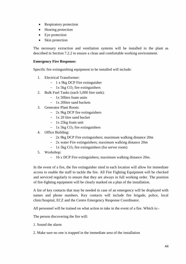
44
Respiratory protection
Hearing protection
Eye protection
Skin protection
The necessary extraction and ventilation systems will be installed in the plant as
described in Section 7.2.2 to ensure a clean and comfortable working environment.
Emergency Fire Response:
Specific fire extinguishing equipment to be installed will include:
1. Electrical Transformer:
1 x 9kg DCP Fire extinguisher
1x 5kg CO2 fire extinguishers
2. Bulk Fuel Tanks (each 5,000 litre tank):
1x 50litre foam units
1x 20litre sand buckets
3. Generator Plant Room:
2x 9kg DCP fire extinguishers
1x 20 litre sand bucket
1x 25kg foam unit
1x 5kg CO2 fire extinguishers
4. Office Building:
2x 9kg DCP Fire extinguishers; maximum walking distance 20m
2x water Fire extinguishers; maximum walking distance 20m
1x 5kg CO2 fire extinguishers (for server room)
5. Workshop:
16 x DCP Fire extinguishers; maximum walking distance 20m.
In the event of a fire, the fire extinguisher sited in each location will allow for immediate
access to enable the staff to tackle the fire. All Fire Fighting Equipment will be checked
and serviced regularly to ensure that they are always in full working order. The position
of fire-fighting equipment will be clearly marked on a plan of the installation.
A list of key contacts that may be needed in case of an emergency will be displayed with
names and phone numbers. Key contacts will include fire brigade, police, local
clinic/hospital, ECZ and the Centre Emergency Response Coordinator.
All personnel will be trained on what action to take in the event of a fire. Which is:-
The person discovering the fire will:
1. Sound the alarm
2. Make sure no one is trapped in the immediate area of the installation
45
3. If safe to do so, tackle the fire with the fire equipment available
The person in-charge will conduct a quick investigation as to the type and size of the fire
and:
1. Make sure the Fire Brigade has been called.
2. Instruct the trained fire team from the employees to tackle the fire.
3. Order all other staff away from the area.
7.2.6 Public Health and Safety
All procedures and waste management protocols to minimize or prevent possible sources
of contamination of soils and the aquatic environment as outlined in Sections 7.2.3 and
7.3 will be strictly observed.
7.3 Waste Management Protocols
Waste and by-products expected to be generated during the construction and operational
phases of the project were listed and discussed in Sections 4.5 and 4.8 respectivelly.
Measures to be put in place for the management of this waste have been discussed under
the relevant headings in Mitigation Measures above (Sections 7.1 and 7.2). For ease of
reference, waste management protocols for the construction and operational phases of the
project are summarized in full in Table 7 below.
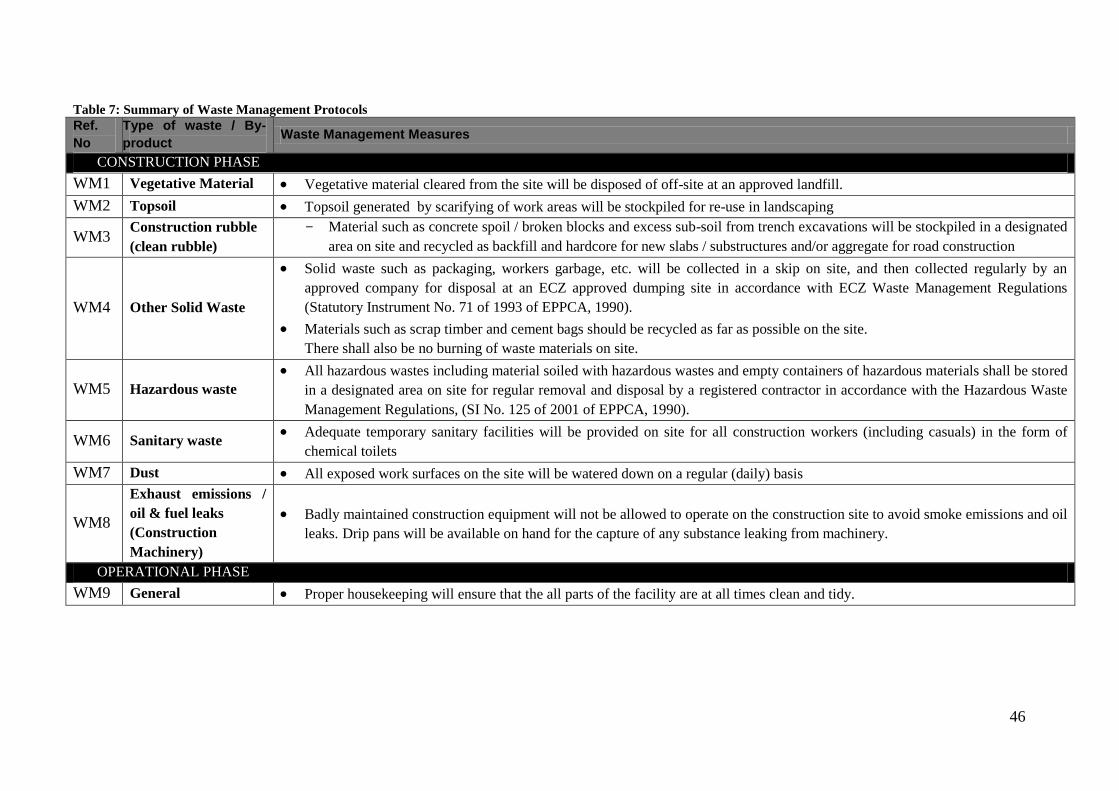
46
Table 7: Summary of Waste Management Protocols
Ref.
No
Type of waste / By-
product Waste Management Measures
CONSTRUCTION PHASE
WM1 Vegetative Material Vegetative material cleared from the site will be disposed of off-site at an approved landfill.
WM2 Topsoil Topsoil generated by scarifying of work areas will be stockpiled for re-use in landscaping
WM3 Construction rubble
(clean rubble)
Material such as concrete spoil / broken blocks and excess sub-soil from trench excavations will be stockpiled in a designated
area on site and recycled as backfill and hardcore for new slabs / substructures and/or aggregate for road construction
WM4 Other Solid Waste
Solid waste such as packaging, workers garbage, etc. will be collected in a skip on site, and then collected regularly by an
approved company for disposal at an ECZ approved dumping site in accordance with ECZ Waste Management Regulations
(Statutory Instrument No. 71 of 1993 of EPPCA, 1990).
Materials such as scrap timber and cement bags should be recycled as far as possible on the site.
There shall also be no burning of waste materials on site.
WM5 Hazardous waste
All hazardous wastes including material soiled with hazardous wastes and empty containers of hazardous materials shall be stored
in a designated area on site for regular removal and disposal by a registered contractor in accordance with the Hazardous Waste
Management Regulations, (SI No. 125 of 2001 of EPPCA, 1990).
WM6 Sanitary waste Adequate temporary sanitary facilities will be provided on site for all construction workers (including casuals) in the form of
chemical toilets
WM7 Dust All exposed work surfaces on the site will be watered down on a regular (daily) basis
WM8
Exhaust emissions /
oil & fuel leaks
(Construction
Machinery)
Badly maintained construction equipment will not be allowed to operate on the construction site to avoid smoke emissions and oil
leaks. Drip pans will be available on hand for the capture of any substance leaking from machinery.
OPERATIONAL PHASE
WM9 General Proper housekeeping will ensure that the all parts of the facility are at all times clean and tidy.
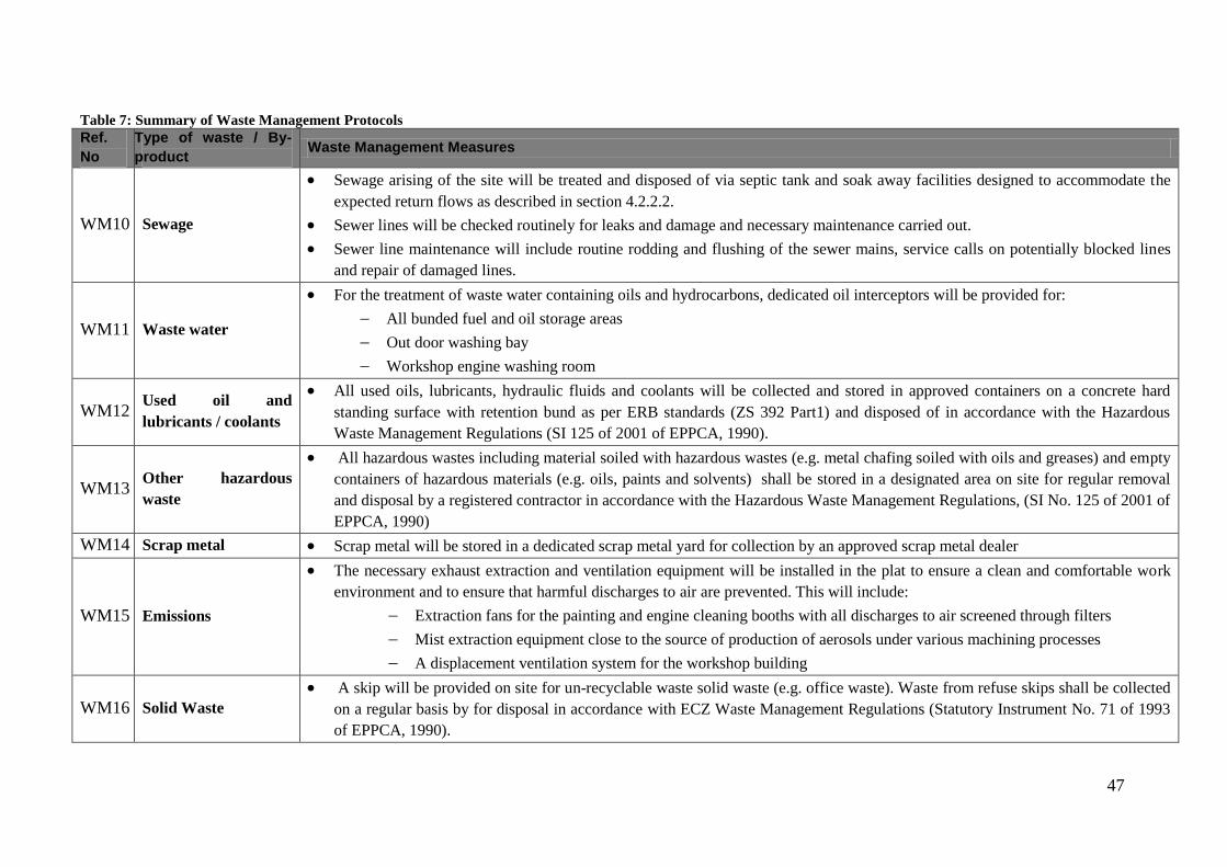
47
Table 7: Summary of Waste Management Protocols
Ref.
No
Type of waste / By-
product Waste Management Measures
WM10 Sewage
Sewage arising of the site will be treated and disposed of via septic tank and soak away facilities designed to accommodate the
expected return flows as described in section 4.2.2.2.
Sewer lines will be checked routinely for leaks and damage and necessary maintenance carried out.
Sewer line maintenance will include routine rodding and flushing of the sewer mains, service calls on potentially blocked lines
and repair of damaged lines.
WM11 Waste water
For the treatment of waste water containing oils and hydrocarbons, dedicated oil interceptors will be provided for:
All bunded fuel and oil storage areas
Out door washing bay
Workshop engine washing room
WM12 Used oil and
lubricants / coolants
All used oils, lubricants, hydraulic fluids and coolants will be collected and stored in approved containers on a concrete hard
standing surface with retention bund as per ERB standards (ZS 392 Part1) and disposed of in accordance with the Hazardous
Waste Management Regulations (SI 125 of 2001 of EPPCA, 1990).
WM13 Other hazardous
waste
All hazardous wastes including material soiled with hazardous wastes (e.g. metal chafing soiled with oils and greases) and empty
containers of hazardous materials (e.g. oils, paints and solvents) shall be stored in a designated area on site for regular removal
and disposal by a registered contractor in accordance with the Hazardous Waste Management Regulations, (SI No. 125 of 2001 of
EPPCA, 1990)
WM14 Scrap metal Scrap metal will be stored in a dedicated scrap metal yard for collection by an approved scrap metal dealer
WM15 Emissions
The necessary exhaust extraction and ventilation equipment will be installed in the plat to ensure a clean and comfortable work
environment and to ensure that harmful discharges to air are prevented. This will include:
Extraction fans for the painting and engine cleaning booths with all discharges to air screened through filters
Mist extraction equipment close to the source of production of aerosols under various machining processes
A displacement ventilation system for the workshop building
WM16 Solid Waste
A skip will be provided on site for un-recyclable waste solid waste (e.g. office waste). Waste from refuse skips shall be collected
on a regular basis by for disposal in accordance with ECZ Waste Management Regulations (Statutory Instrument No. 71 of 1993
of EPPCA, 1990).
48
8.0 Environmental Management and Monitoring Plan (EMMP)
An Environmental Management and Monitoring Plan is laid out in Table 9 below. Many
of the environmental issues related to the project have been considered in the design
phase, thus they form part of the mitigation measures. As such, these form part of the
EMMP, and are summarised in Table 8.
Ultimate responsibility for Environmental Management at all project phases will be that
of the Managing Director of HCMZ. Compliance with relevant Health, Safety and
Environmental standards during construction will be the prime responsibility of the
Contractor. During operation, Senior HCMZ Management will be fully responsible for
the implementation of Environmental Management and Monitoring activities and
ensuring full compliance with Health, Safety and Environmental standards.
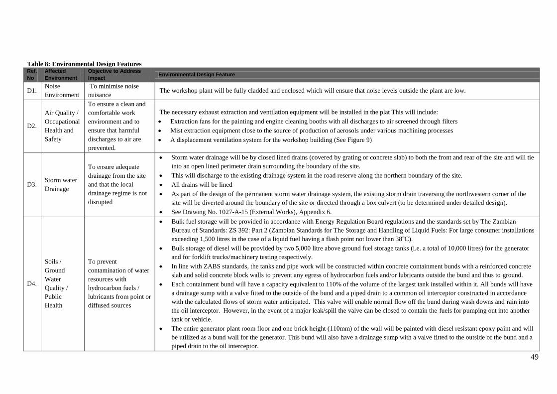
49
Table 8: Environmental Design Features Ref.
No
Affected
Environment
Objective to Address
Impact Environmental Design Feature
D1. Noise
Environment
To minimise noise
nuisance The workshop plant will be fully cladded and enclosed which will ensure that noise levels outside the plant are low.
D2.
Air Quality /
Occupational
Health and
Safety
To ensure a clean and
comfortable work
environment and to
ensure that harmful
discharges to air are
prevented.
The necessary exhaust extraction and ventilation equipment will be installed in the plat This will include:
Extraction fans for the painting and engine cleaning booths with all discharges to air screened through filters
Mist extraction equipment close to the source of production of aerosols under various machining processes
A displacement ventilation system for the workshop building (See Figure 9)
D3. Storm water
Drainage
To ensure adequate
drainage from the site
and that the local
drainage regime is not
disrupted
Storm water drainage will be by closed lined drains (covered by grating or concrete slab) to both the front and rear of the site and will tie
into an open lined perimeter drain surrounding the boundary of the site.
This will discharge to the existing drainage system in the road reserve along the northern boundary of the site.
All drains will be lined
As part of the design of the permanent storm water drainage system, the existing storm drain traversing the northwestern corner of the
site will be diverted around the boundary of the site or directed through a box culvert (to be determined under detailed design).
See Drawing No. 1027-A-15 (External Works), Appendix 6.
D4.
Soils /
Ground
Water
Quality /
Public
Health
To prevent
contamination of water
resources with
hydrocarbon fuels /
lubricants from point or
diffused sources
Bulk fuel storage will be provided in accordance with Energy Regulation Board regulations and the standards set by The Zambian
Bureau of Standards: ZS 392: Part 2 (Zambian Standards for The Storage and Handling of Liquid Fuels: For large consumer installations
exceeding 1,500 litres in the case of a liquid fuel having a flash point not lower than 38oC).
Bulk storage of diesel will be provided by two 5,000 litre above ground fuel storage tanks (i.e. a total of 10,000 litres) for the generator
and for forklift trucks/machinery testing respectively.
In line with ZABS standards, the tanks and pipe work will be constructed within concrete containment bunds with a reinforced concrete
slab and solid concrete block walls to prevent any egress of hydrocarbon fuels and/or lubricants outside the bund and thus to ground.
Each containment bund will have a capacity equivalent to 110% of the volume of the largest tank installed within it. All bunds will have
a drainage sump with a valve fitted to the outside of the bund and a piped drain to a common oil interceptor constructed in accordance
with the calculated flows of storm water anticipated. This valve will enable normal flow off the bund during wash downs and rain into
the oil interceptor. However, in the event of a major leak/spill the valve can be closed to contain the fuels for pumping out into another
tank or vehicle.
The entire generator plant room floor and one brick height (110mm) of the wall will be painted with diesel resistant epoxy paint and will
be utilized as a bund wall for the generator. This bund will also have a drainage sump with a valve fitted to the outside of the bund and a
piped drain to the oil interceptor.

50
Table 8: Environmental Design Features Ref.
No
Affected
Environment
Objective to Address
Impact Environmental Design Feature
The off-loading pump, fuel filters and supply and return feeds will also be located within the same bund in order to prevent any fuel or
lubricant leaks to ground due to pipe leaks or pump seal failure.
The loading / off loading point to and from vehicles will comprise a hard standing surface with drainage to the oil interceptor.
A drawing showing standard installation layout and details for a 5,000 litre above ground steel skid tank is given in Appendix 8. A
detailed drawing of the oil interceptor is given in Appendix 9.
Dedicated oil interceptors will be provided for the outdoor washing bay and workshop engine washing room through which all oil
containing wastewater produced in these areas will be directed and treated prior to discharge to the site drainage system.
A boundary oil interceptor will also be located at the outfall point of the site drainage system to the local road storm water drainage
system along the northern boundary of the site to provide overall treatment of all stormwater / waste water runoff emanating from the site
prior to discharge to the aquatic environment.
A dedicated storage room shall be provided for oils, lubricants and paints in approved containers on a concrete hard standing surface
with retention bund as per ERB standards (ZS 392 Part1).
All used oils, lubricants, hydraulic fluids and coolants will be collected and stored in approved containers on a concrete hard standing
surface with retention bund as per ERB standards (ZS 392 Part1).
All hazardous wastes including material soiled with hazardous wastes (e.g. metal chafing soiled with oils and greases) and empty
containers of hazardous materials (e.g. oils, paints and solvents) shall be stored in a designated area
D5.
Ground
Water
Quality /
Public
Health
To prevent
contamination of water
resources by sewage
Sewage arising of the site will be treated and disposed of via septic tank and soak away facilities designed to accommodate the expected
return flows. A standard drawing showing standard septic tank and soakaway details is given in Appendix 7.
D6.
Fire
Protection /
Occupational
and Public
Health and
safety
To minimise potential
risks of fire
The development will be equipped with all necessary smoke and fire detection systems and alarms and will also have installed fire
fighting equipment to satisfy and/or exceed Local Building Regulations.
Specific fire extinguishing equipment to be installed will include:
1. Electrical Transformer:
1 x 9kg DCP Fire extinguisher
1x 5kg CO2 fire extinguishers
2. Bulk Fuel Tanks (each 5,000 litre tank):
1x 50litre foam units
1x 20litre sand buckets
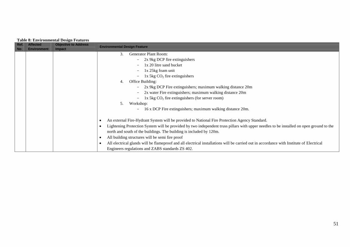
51
Table 8: Environmental Design Features Ref.
No
Affected
Environment
Objective to Address
Impact Environmental Design Feature
3. Generator Plant Room:
2x 9kg DCP fire extinguishers
1x 20 litre sand bucket
1x 25kg foam unit
1x 5kg CO2 fire extinguishers
4. Office Building:
2x 9kg DCP Fire extinguishers; maximum walking distance 20m
2x water Fire extinguishers; maximum walking distance 20m
1x 5kg CO2 fire extinguishers (for server room)
5. Workshop:
16 x DCP Fire extinguishers; maximum walking distance 20m.
An external Fire-Hydrant System will be provided to National Fire Protection Agency Standard.
Lightening Protection System will be provided by two independent truss pillars with upper needles to be installed on open ground to the
north and south of the buildings. The building is included by 120m.
All building structures will be semi fire proof
All electrical glands will be flameproof and all electrical installations will be carried out in accordance with Institute of Electrical
Engineers regulations and ZABS standards ZS 402.
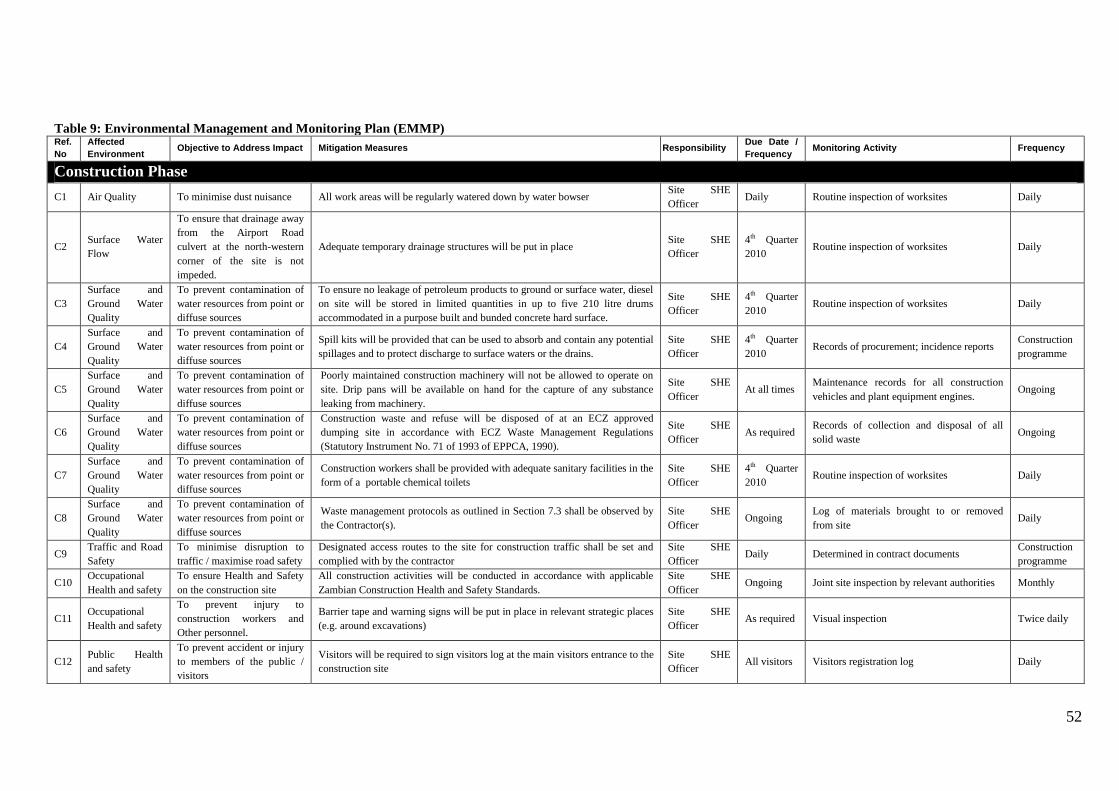
52
Table 9: Environmental Management and Monitoring Plan (EMMP) Ref.
No
Affected
Environment Objective to Address Impact Mitigation Measures Responsibility
Due Date /
Frequency Monitoring Activity Frequency
Construction Phase
C1 Air Quality To minimise dust nuisance All work areas will be regularly watered down by water bowser Site SHE
Officer Daily Routine inspection of worksites Daily
C2 Surface Water
Flow
To ensure that drainage away
from the Airport Road
culvert at the north-western
corner of the site is not
impeded.
Adequate temporary drainage structures will be put in place Site SHE
Officer
4th Quarter
2010 Routine inspection of worksites Daily
C3
Surface and
Ground Water
Quality
To prevent contamination of
water resources from point or
diffuse sources
To ensure no leakage of petroleum products to ground or surface water, diesel
on site will be stored in limited quantities in up to five 210 litre drums
accommodated in a purpose built and bunded concrete hard surface.
Site SHE
Officer
4th Quarter
2010 Routine inspection of worksites Daily
C4
Surface and
Ground Water
Quality
To prevent contamination of
water resources from point or
diffuse sources
Spill kits will be provided that can be used to absorb and contain any potential
spillages and to protect discharge to surface waters or the drains.
Site SHE
Officer
4th Quarter
2010 Records of procurement; incidence reports
Construction
programme
C5
Surface and
Ground Water
Quality
To prevent contamination of
water resources from point or
diffuse sources
Poorly maintained construction machinery will not be allowed to operate on
site. Drip pans will be available on hand for the capture of any substance
leaking from machinery.
Site SHE
Officer At all times
Maintenance records for all construction
vehicles and plant equipment engines. Ongoing
C6
Surface and
Ground Water
Quality
To prevent contamination of
water resources from point or
diffuse sources
Construction waste and refuse will be disposed of at an ECZ approved
dumping site in accordance with ECZ Waste Management Regulations
(Statutory Instrument No. 71 of 1993 of EPPCA, 1990).
Site SHE
Officer As required
Records of collection and disposal of all
solid waste Ongoing
C7
Surface and
Ground Water
Quality
To prevent contamination of
water resources from point or
diffuse sources
Construction workers shall be provided with adequate sanitary facilities in the
form of a portable chemical toilets
Site SHE
Officer
4th Quarter
2010 Routine inspection of worksites Daily
C8
Surface and
Ground Water
Quality
To prevent contamination of
water resources from point or
diffuse sources
Waste management protocols as outlined in Section 7.3 shall be observed by
the Contractor(s).
Site SHE
Officer Ongoing
Log of materials brought to or removed
from site Daily
C9 Traffic and Road
Safety
To minimise disruption to
traffic / maximise road safety
Designated access routes to the site for construction traffic shall be set and
complied with by the contractor
Site SHE
Officer Daily Determined in contract documents
Construction
programme
C10 Occupational
Health and safety
To ensure Health and Safety
on the construction site
All construction activities will be conducted in accordance with applicable
Zambian Construction Health and Safety Standards.
Site SHE
Officer Ongoing Joint site inspection by relevant authorities Monthly
C11 Occupational
Health and safety
To prevent injury to
construction workers and
Other personnel.
Barrier tape and warning signs will be put in place in relevant strategic places
(e.g. around excavations)
Site SHE
Officer As required Visual inspection Twice daily
C12 Public Health
and safety
To prevent accident or injury
to members of the public /
visitors
Visitors will be required to sign visitors log at the main visitors entrance to the
construction site
Site SHE
Officer All visitors Visitors registration log Daily
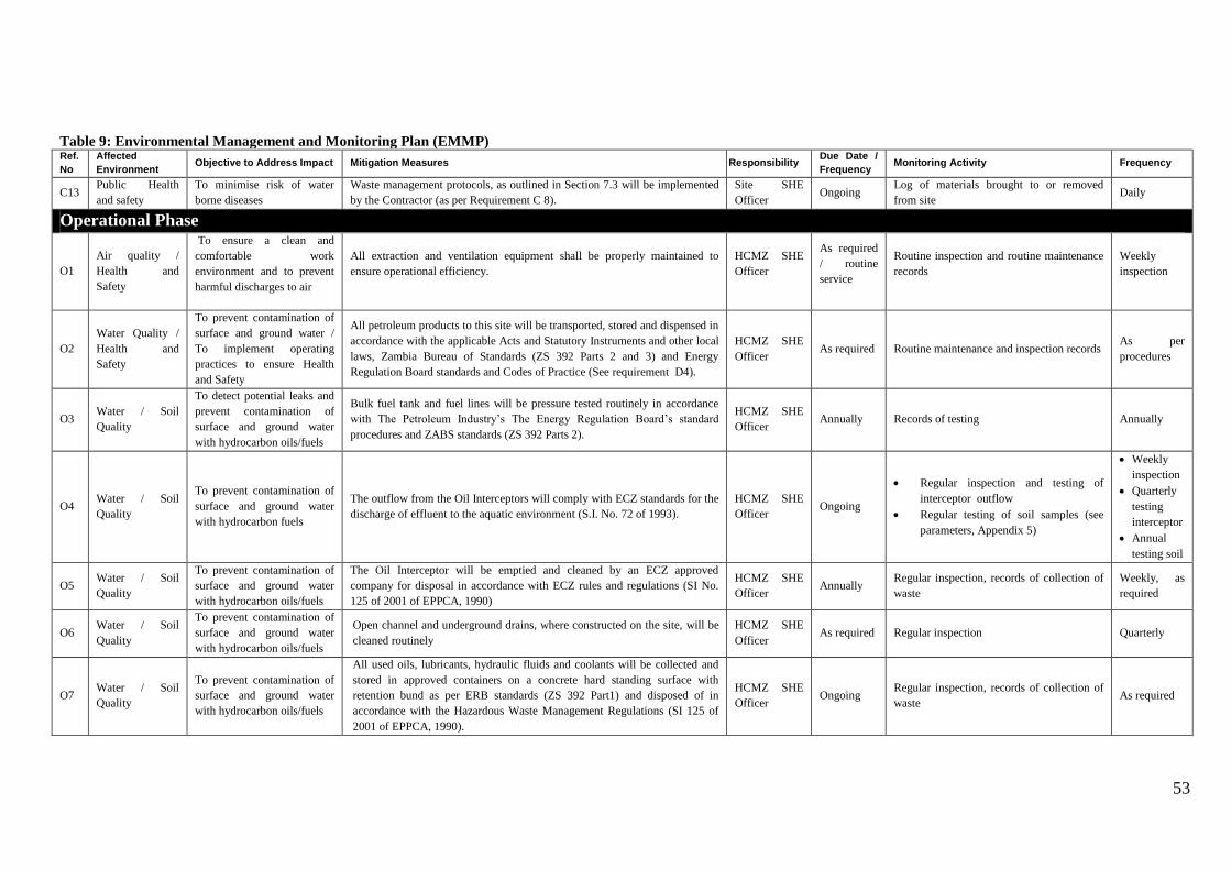
53
Table 9: Environmental Management and Monitoring Plan (EMMP) Ref.
No
Affected
Environment Objective to Address Impact Mitigation Measures Responsibility
Due Date /
Frequency Monitoring Activity Frequency
C13 Public Health
and safety
To minimise risk of water
borne diseases
Waste management protocols, as outlined in Section 7.3 will be implemented
by the Contractor (as per Requirement C 8).
Site SHE
Officer Ongoing
Log of materials brought to or removed
from site Daily
Operational Phase
O1
Air quality /
Health and
Safety
To ensure a clean and
comfortable work
environment and to prevent
harmful discharges to air
All extraction and ventilation equipment shall be properly maintained to
ensure operational efficiency.
HCMZ SHE
Officer
As required
/ routine
service
Routine inspection and routine maintenance
records
Weekly
inspection
O2
Water Quality /
Health and
Safety
To prevent contamination of
surface and ground water /
To implement operating
practices to ensure Health
and Safety
All petroleum products to this site will be transported, stored and dispensed in
accordance with the applicable Acts and Statutory Instruments and other local
laws, Zambia Bureau of Standards (ZS 392 Parts 2 and 3) and Energy
Regulation Board standards and Codes of Practice (See requirement D4).
HCMZ SHE
Officer As required Routine maintenance and inspection records
As per
procedures
O3 Water / Soil
Quality
To detect potential leaks and
prevent contamination of
surface and ground water
with hydrocarbon oils/fuels
Bulk fuel tank and fuel lines will be pressure tested routinely in accordance
with The Petroleum Industry’s The Energy Regulation Board’s standard
procedures and ZABS standards (ZS 392 Parts 2).
HCMZ SHE
Officer Annually Records of testing Annually
O4 Water / Soil
Quality
To prevent contamination of
surface and ground water
with hydrocarbon fuels
The outflow from the Oil Interceptors will comply with ECZ standards for the
discharge of effluent to the aquatic environment (S.I. No. 72 of 1993).
HCMZ SHE
Officer Ongoing
Regular inspection and testing of
interceptor outflow
Regular testing of soil samples (see
parameters, Appendix 5)
Weekly
inspection
Quarterly
testing
interceptor
Annual
testing soil
O5 Water / Soil
Quality
To prevent contamination of
surface and ground water
with hydrocarbon oils/fuels
The Oil Interceptor will be emptied and cleaned by an ECZ approved
company for disposal in accordance with ECZ rules and regulations (SI No.
125 of 2001 of EPPCA, 1990)
HCMZ SHE
Officer Annually
Regular inspection, records of collection of
waste
Weekly, as
required
O6 Water / Soil
Quality
To prevent contamination of
surface and ground water
with hydrocarbon oils/fuels
Open channel and underground drains, where constructed on the site, will be
cleaned routinely
HCMZ SHE
Officer As required Regular inspection Quarterly
O7 Water / Soil
Quality
To prevent contamination of
surface and ground water
with hydrocarbon oils/fuels
All used oils, lubricants, hydraulic fluids and coolants will be collected and
stored in approved containers on a concrete hard standing surface with
retention bund as per ERB standards (ZS 392 Part1) and disposed of in
accordance with the Hazardous Waste Management Regulations (SI 125 of
2001 of EPPCA, 1990).
HCMZ SHE
Officer Ongoing
Regular inspection, records of collection of
waste As required
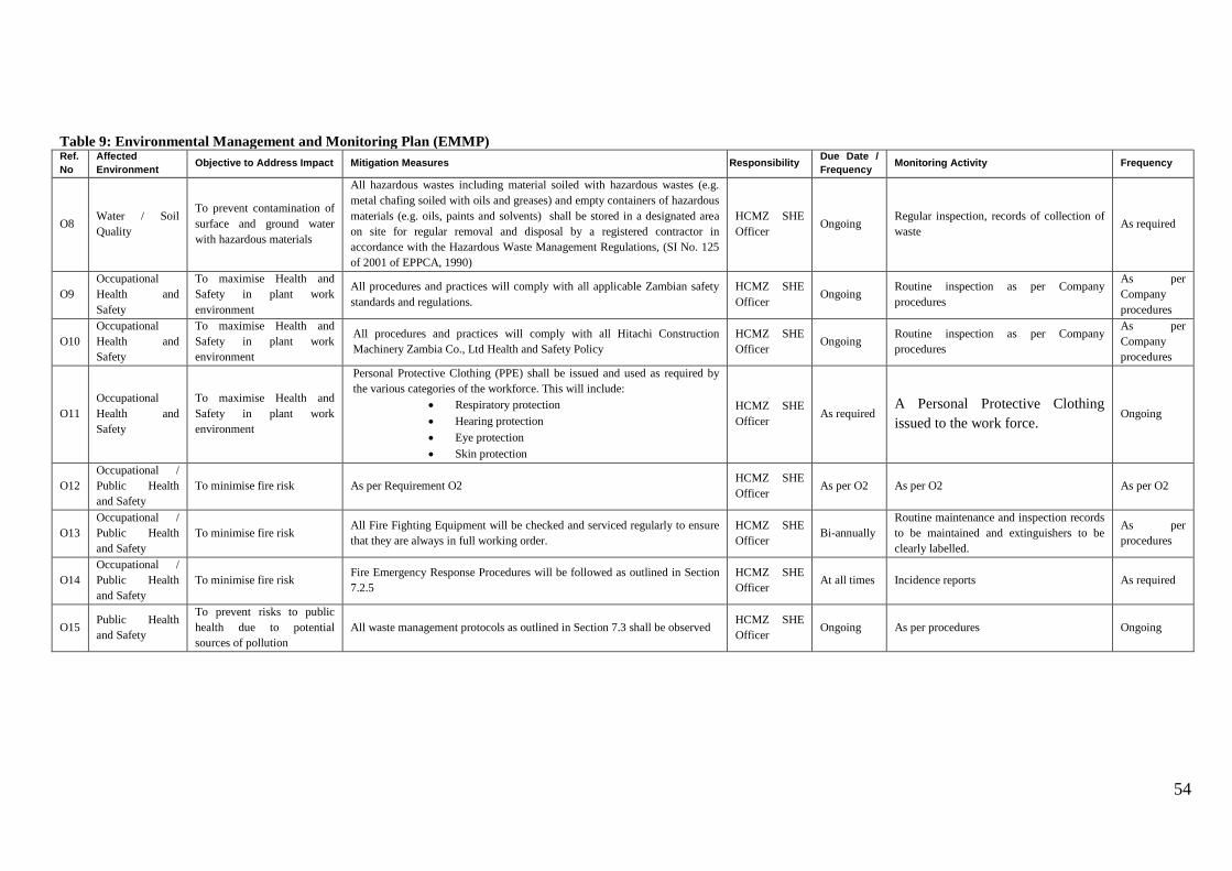
54
Table 9: Environmental Management and Monitoring Plan (EMMP) Ref.
No
Affected
Environment Objective to Address Impact Mitigation Measures Responsibility
Due Date /
Frequency Monitoring Activity Frequency
O8 Water / Soil
Quality
To prevent contamination of
surface and ground water
with hazardous materials
All hazardous wastes including material soiled with hazardous wastes (e.g.
metal chafing soiled with oils and greases) and empty containers of hazardous
materials (e.g. oils, paints and solvents) shall be stored in a designated area
on site for regular removal and disposal by a registered contractor in
accordance with the Hazardous Waste Management Regulations, (SI No. 125
of 2001 of EPPCA, 1990)
HCMZ SHE
Officer Ongoing
Regular inspection, records of collection of
waste As required
O9
Occupational
Health and
Safety
To maximise Health and
Safety in plant work
environment
All procedures and practices will comply with all applicable Zambian safety
standards and regulations.
HCMZ SHE
Officer Ongoing
Routine inspection as per Company
procedures
As per
Company
procedures
O10
Occupational
Health and
Safety
To maximise Health and
Safety in plant work
environment
All procedures and practices will comply with all Hitachi Construction
Machinery Zambia Co., Ltd Health and Safety Policy
HCMZ SHE
Officer Ongoing
Routine inspection as per Company
procedures
As per
Company
procedures
O11
Occupational
Health and
Safety
To maximise Health and
Safety in plant work
environment
Personal Protective Clothing (PPE) shall be issued and used as required by
the various categories of the workforce. This will include:
Respiratory protection
Hearing protection
Eye protection
Skin protection
HCMZ SHE
Officer As required
A Personal Protective Clothing
issued to the work force. Ongoing
O12
Occupational /
Public Health
and Safety
To minimise fire risk As per Requirement O2 HCMZ SHE
Officer As per O2 As per O2 As per O2
O13
Occupational /
Public Health
and Safety
To minimise fire risk All Fire Fighting Equipment will be checked and serviced regularly to ensure
that they are always in full working order.
HCMZ SHE
Officer Bi-annually
Routine maintenance and inspection records
to be maintained and extinguishers to be
clearly labelled.
As per
procedures
O14
Occupational /
Public Health
and Safety
To minimise fire risk Fire Emergency Response Procedures will be followed as outlined in Section
7.2.5
HCMZ SHE
Officer At all times Incidence reports As required
O15 Public Health
and Safety
To prevent risks to public
health due to potential
sources of pollution
All waste management protocols as outlined in Section 7.3 shall be observed HCMZ SHE
Officer Ongoing As per procedures Ongoing

55
9.0 Conclusion
It is our professional opinion that the proposed development as described above is
approved to operate on the basis that:
1. A number of social and economic benefits are expected to result from the project
which will include providing an economic boost to industrial sectors employing
heavy duty earth moving machinery by offering cost effective maintenance solutions,
technology and skills transfer through the Company’s training programmes and
promotion of Zambia as a regional business hub.
2. All steps to prevent fuel, oil and waste water contamination to ground and the aquatic
environment will be incorporated in the design, construction and operation of the
facility.
3. Safe working practices and adherence to safety regulations will be given high priority
during both construction and operational phases of the project.
We are also of the opinion that the project proposals for the construction operation of the
remanufacturing facility will satisfy the laws and regulations of Zambia.

56
APPENDICES
57
Appendix 1:
Certificate of Incorporation
58
Appendix 2:
Application for Planning Permission

59
Appendix 3:
Letter to ECZ from NISIR Dated 1 November,
2010
60
Appendix 4:
Geotechnical Report

61
Appendix 5:
Soil Testing Results

62
Appendix 6:
Project Layout and Design Drawings
1027-A-06: Site Plan
1027-A-07: Ground Floor Plans
1027-A-08: 1st Floor Plans
1027-A-09: Roof Plans
1027-A-10: Elevations
1027-A-11: Sections
1027-A-15: External Works

63
Appendix 7:
Standard Septic Tank and Soakaway Details

64
Appendix 8:
Standard installation layout and details for a
5,000 litre above ground steel skid tank

65
Appendix 9:
Standard Oil Interceptor Details
Top Related