


Languages
Pages
Legal


HDO6000 High Definition Oscilloscopes350 MHz – 1 GHz
Key Features
• 12-bit ADC resolution, up to 15-bit with enhanced resolution
• 350 MHz, 500 MHz, and 1 GHz bandwidths
• Long Memory – up to 250 Mpts/Ch
• 12.1” touch screen display
• Advanced Tools
– Spectrum Analyzer Mode
– WaveScan – Search and Find
– LabNotebook Documentation and Report Generation
– History Mode - Waveform Playback
• Advanced Triggering with TriggerScan and Measurement Trigger
• Power Analyzer Option
• Serial Data Trigger, Decode and Debug Toolkit Options
• 16 Digital Channels with 1.25 GS/s
– Analog and Digital Cross-PatternTriggering – Digital Pattern Search and Find – AnalogandDigitalTiming Measurements
– Logic Gate Emulation
– Activity Indicators
HD4096 TechnologyHD4096highdefinitiontechnologyconsists of high sample rate 12-bit ADCs,highsignal-to-noiseinputamplifiersandalow-noisesystemarchitecture.Thistechnologyenableshighdefinitionoscilloscopestocaptureanddisplaysignalsofupto1GHzwithhigh sample rate and 16 times more resolution than other oscilloscopes.
Long MemoryWith up to 250 Mpts of memory the HDO6000HighDefinitionOscilloscopescan capture large amounts of data withmoreprecisionthanotheroscilloscopes.The2.5GS/s,250Mpts architecture provides the ability to capture a fast transient or a long acquisition.
Large 12.1” Touch ScreenNavigating complicated user interfaces is a thing of the past thanks to the large touch screen display of the HDO6000. Theuserinterfacewasdesignedfortouchscreenswhichmakesnavigatingthe HDO6000 extremely intuitive.
Comprehensive Analysis ToolsAdvanced math and measurement parameters quantify analog and digital waveformswhiletracks,trendsandhistogramsshowhowtheychangeovertime.AdvancedtriggeringwithTriggerScanandMeasurementTriggerensure even the most complicated signals are captured.
Combining Teledyne LeCroy’s HD4096 high definition 12-bit technology, with long memory, a compact form factor, 12.1” touch screen display, powerful measurement and analysis tools, and mixed signal capability, the HDO6000 is the ideal oscilloscope for circuit validation, system debug and waveform analysis. The powerful feature set provides analytical tools and unique application packages to streamline the testing process. Tools such as WaveScan Search and Find and History Mode, combined with advanced triggering, identify and isolate problems while Spectrum Analyzer Mode provides analysis tools in the frequency domain.

2
HD4096 HIGH DEFINITION TECHNOLOGY
HD4096 high definition technology consists of high sample rate 12-bit ADCs, high signal-to-noise ratio amplifiers and a low-noise system architecture. This technology enables high definition oscilloscopes to capture and display signals of up to 1 GHz with high sample rate and 16 times more resolution than other oscilloscopes.
OscilloscopeswithHD4096technologyhavehigherresolutionandmeasurementprecisionthan8-bitalternatives.Thehighsamplerate12-bitADCsprovidehighresolutionsamplingatupto2.5GS/s.Thehighperformanceinputamplifiersdeliverphenomenalsignalfidelitywitha55dBsignal-to-noiseratioandprovideapristinesignaltotheADCtobedigitized.Thelow-noisesignalarchitectureensuresthatnothinginterfereswiththecapturedsignalandtheoscilloscopedisplaysawaveformthataccurately represents the signals from the device under test.
High Sample Rate 12-bit
ADC’s
High Signal to Noise Input
Amplifiers
Low Noise System
Architecture
16x More Resolution12-bitsofverticalresolutionprovidessixteentimesmoreresolutionthan8-bits.The4096discretelevelsreducethequantizationerror.Signalscapturedwithlowerresolutionoscilloscopeshaveahigherlevelofquantizationerrorresultinginlessaccuratewaveformsonthedisplay.Signalscapturedonanoscilloscopewith12-bitHD4096technologyareaccuratelydisplayedwithminimalquantizationerror.
Digitized Waveform
Signal from Device Under Test
16x Closer to Perfect 8-bit 12-bit
Quantization Error

3
DEBUG IN HIGH DEFINITION WITH HD4096
Clean, Crisp Waveforms
Whencomparedtowaveformscapturedanddisplayedby8-bitoscilloscopes,waveformscapturedwithHD4096technology are dramatically crisper and cleaner.OscilloscopeswithHD4096 acquirewaveformsathighresolution,highsamplerateandlownoiseto displaythemostaccuratewaveforms.
More Signal Details
Signal details often lost in the noise are clearly visible and easy to distin-guishwhencapturedonoscilloscopeswithHD4096.Detailswhichwere previouslydifficulttoevenseecannowbe easily seen and measured. Using the oscilloscope zoom capabilities gives an even closer look at the details for unparalleled insight to the signals on screen.
Unmatched Measurement Precision
Precise measurements are critical for effective debug and analysis. HD4096 enables oscilloscopes to deliver unmatched measurement precision to improve testing capabilities and provide better results.
Oscilloscopes with HD4096 have a variety of benefits that allow the user to debug in high definition. Waveforms displayed by high definition oscilloscopes are cleaner and crisper. More signal details can be seen and measured; these measurements are made with unmatched precision resulting in better test results and shorter debug time.
8-bit 12-bit
A
A A
B BC C
B
C
Clean, Crisp Waveforms | Thintracesshowtheactualwaveformwithminimalnoiseinterference
Unmatched Measurement Precision | Measurements are more precise and not affected by quantization noise
More Signal Details | Waveformdetailslostonan8-bitoscilloscopecannowbeclearlyseen

4
TOUCH SCREEN SIMPLICITY
Don’twastetimesearchingthroughacomplexmenustruc-turetofindthepropersetting.ConfiguringtheHDO6000issimple thanks to the intuitive touch screen user interface. Everythingonthescreenisinteractive.Toadjustchannel,timebase,ortriggersettings,simplytouchtheassociateddescriptor box and the appropriate menu is opened.
Measurementscanbetouchedtoadjusttheirsettingsand cursors can be positioned precisely by touching and draggingthemtotheproperlocation.Aboxcanbedrawnaroundaportionofawaveformtocreateazoomofthatwaveform.Evenwaveformoffsetanddelaycanbe adjustedsimplybytouchinganddraggingthewaveform.

5
ADVANCED TOOLS FOR WAVEFORM ANALYSIS
Spectrum Analyzer Mode Viewsignaldetailsinthefrequencydomainwithaspectrumanalyzerstyle user interface.
LabNotebook Documentation and Report Generation Tool Saveallresultsanddatawitha single button press and create customreportswithLabNotebook.
WaveScan Advanced Search and Find Tool Quicklyscananalog,digitalor parallelbussignalsforrunts,glitchesorotheranomalieswithWaveScan.
Sequence Mode Acquisition Capturemanyfastpulsesinquick succession or events separated by long periods of time.
History Mode Waveform Playback Scroll back in time to isolate anomalies that have previously beencapturedtoquicklyfindthesource of the problem.
Serial Bus Trigger and Decode Viewprotocolinformationontopofanalogordigitalwaveforms,triggeronmessages,extractandgraphdatato monitor system performance.
Powerful Mixed Signal Capability Debug complex embedded designs withintegrated16channelmixed signal capability. Each of the 16 digitalchannelssamplesat1.25GS/s andcanutilizeupto125Mpts/ch.PowerfuldebugtoolslikeAnalog/DigitalCross-PatternTriggers,DigitalTimingMeasurements,Parallel PatternSearch,ActivityIndicators,andLogicGateEmulation,makeitpossible to solve complex embedded design problems easily.

6
HDO6000 High Definition Oscilloscopes combine Teledyne LeCroy’s HD4096 high definition technology with long memory, powerful debug tools and mixed signal capability in a compact form factor with a 12.1” touch screen display.
1. Only13cm(5”)Deep–Themost space-efficientoscilloscopeforyour bench from 350 MHz to 1 GHz
2. 12.1” Widescreen (16 x 9) high resolution WXGAcolortouchscreendisplay.Themosttime-efficientuserinterfaceiseveneasiertousewithabuilt-instylus
3. Local language user interface – Select from 10 language preferences. Add a front panel overlaywithyourlocallanguage
4. “Push” Knobs – All knobs have push functionality that provides shortcuts to commonactionssuchasSettoVariable,FindTriggerLevel,ZeroOffset,andZeroDelay
5. WaveformControlKnobs–Controlchannel,zoom,mathandmemorytraceswiththemultiplexed vertical and horizontal knobs
HDO6000 - HIGH DEFINITION OSCILLOSCOPE
2
1
8
10

7
6. DedicatedCursorKnob–Selecttypeofcursor,positionthemonyoursignal,andreadvalueswithouteveropeningamenu
7. Dedicated buttons to quickly access popular debug tools.
8. EasyconnectivitywithtwoconvenientUSBportsonthefront,twoontheside
9. MixedSignalCapability-Debugcomplexembeddeddesignswithintegrated16channelmixed signal capability
10. RotatingandTiltingFeetprovide4differentviewingpositions
11. AuxiliaryOutputandReferenceClock Input/Outputconnectorsforconnectingto other equipment
12. USBTMC(TestandMeasurementClass)portsimplifiesprogramming
Document and Share:
•QuicklysaveallfileswithLabNotebook
•CreatecustomreportswithLabNotebook
•Savetointernalharddiskornetworkdrive
•PrinttoaUSBprinter
•SavetoUSBmemorystick
•ConnectwithLANorGPIB
•ViewdataonaPCwithfreeWaveStudioutility
5
4
6
7
3
8
10
911 12

8
POWERFUL MIXED SIGNAL CAPABILITIES
High-performance 16-Channel Mixed Signal CapabilityWithembeddedsystemsgrowingmorecomplex,powerfulmixedsignaldebug capabilities are an essential part ofmodernoscilloscopes.The16inte-grated digital channels and set of tools designedtoview,measureandanalyzeanalog and digital signals enable fast debugging of mixed signal designs.
Extensive TriggeringFlexible analog and digital cross-pattern triggering across all 20 channels provides the ability to quickly identify and isolate problems in an embedded system. Event triggering can be con-figuredtoarmonananalogsignalandtrigger on a digital pattern.
Advanced Digital Debug ToolsUsingthepowerfulparallelpatternsearchcapabilityofWaveScan,patternsacross many digital lines can be iso-latedandanalyzed.Identifiedpatternsarepresentedinatablewithtimestampinformation and enables quick search-ing for each pattern occurrence. Use a variety of the many timing parameters to measure and analyze the characteristics of digital busses. Powerfultoolsliketracks,trends, statistics and histicons provide addi-tionalinsightandhelpfindanomalies. Quickly see the state of all the digital lines at the same time using convenient activity indicators. Simulate complete digital designs using logicgateemulation.Whenusedwiththewebeditor,manylogicgatescanbecombined together in one math func-tion to simulate complex logic designs. ChoosefromAND,OR,NAND,NOR,XOR,NOTandDFlipFlopgates.
Teledyne LeCroy’s HDO6000-MS High Definition mixed signal oscilloscope combines the high definition analog channels of the HDO6000 with the flexibility of 16 digital inputs. In addition, the many triggering and decoding options turn the HDO6000-MS into an all-in-one analog, digital, serial debug machine.

9
SERIAL TRIGGER AND DECODE OPTIONS
Trigger and DecodeTheserialdatatriggerwillquicklyiso-late events on a bus eliminating the need to set manual triggers and hoping tocatchtherightinformation.Triggerconditions can be entered in binary or hexadecimal formats and conditional triggercapabilitiesevenallowtrigger-ing on a range of different events. Protocoldecodingisshowndirectlyonthewaveformwithanintuitive,color-coded overlay and presented in binary,hexorASCII.DecodingontheHDO6000isfastevenwithlongmem-oryandzoomingintothewaveformshowsprecisebytebybytedecoding.
Table and SearchTofurthersimplifythedebugprocessall decoded data can be displayed in a tablebelowthewaveformgrid.Select-inganentryinthetablewiththetouchscreenwilldisplayjustthatevent. Additionally,built-insearchfunctional-itywillfindspecificdecodedvalues. Serial data messages can be quickly locatedbysearchingonaddress,dataandotherattributesspecifictoa particularprotocol.Oncefound,thespecificlocationcontainingthe specifiedsearchcriteriacanbeauto-matically zoomed to.
View decoded protocol information on top of physical layer waveforms and trigger on protocol specific messages.
PROTObus MAG Serial Debug ToolkitPROTObusMAGSerialDataDebugToolkitextendsthetriggerand decode functions of serial data through integration of measure-mentparameterswithwaveformmath. Nine additional measurements quickly sets up and displays encoded dataasananalogwaveform.Definespecificdataframefiltersanddatafieldtriggerstoconfirmperformanceof embedded nodes.
Supported Serial Data Protocols
• I2C, SPI, UART
• CAN, LIN, FlexRay™, SENT
• Ethernet 10/100BaseT, USB 1.0/1.1/2.0, USB 2.0-HSIC
• Audio (I2S, LJ, RJ, TDM)
• MIL-STD-1553, ARINC 429
• MIPI D-PHY, DigRF 3G, DigRFv4
• Manchester, NRZ
Debugging serial data busses can be confusing and time consuming. The serial data and decode options for HDO6000-MS provide time saving tools for serial bus debug and validation.

10
IDENTIFY AND ISOLATE PROBLEMS FASTER
WaveScan Advanced SearchWaveScan provides powerful isolation capabilities that hardware triggers can’t provide. WaveScan allows searching analog, digital or parallel bus signal in a single acquisition using more than 20 different criteria. Or, set up a scan condition and scan for an event over hours or even days.
Since the scanning “modes” are not simplycopiesofthehardwaretriggers,the utility and capa bility is much higher. Forinstance,thereisno“frequency”trig-gerinanyoscilloscope,yetWaveScanallowsfor“frequency”tobequickly“scanned.”Thisallowstheusertoaccu-mulate a data set of unusual events that areseparatedbyhoursordays,enablingfaster debugging. When used in multiple acquisitions,WaveScanbuildsonthe traditionalTeledyneLeCroystrength of fast processing of data. Quickly scan millions of events looking for unusual occurrences,anddoitmuchfaster
andmoreefficientlythanother oscilloscopes can. Found events can beoverlaidwiththeScanOverlaytoprovide a quick comparison of events; measurement based scans populate theScanHistogramtoshowthestatisti-cal distribution of the events. Using the powerfulparallelpatternsearchcapabil-ityofWaveScan,patternsacrossmanydigital lines can be isolated and ana-lyzed.Identifiedpatternsarepresentedinatablewithtimestampinformationand enables quick searching for each pattern occurrence.
Advanced Waveform Capture with Sequence ModeUse Sequence mode to store up to 65,000triggeredeventsas“segments”intomemory.Thiscanbeidealwhencapturing many fast pulses in quick successionorwhencapturingeventsseparated by long time periods. Sequence mode provides timestamps for each acquisition and minimizes dead-timebetweentriggerstolessthan1μs.CombineSequencemodewithadvanced triggers to isolate rare events overtimeandanalyzeafterwards.
Advanced Math and MeasureWith many math functions and measurementparametersavailable,theHDO6000 can measure and analyze every aspect of analog and digital waveforms.ByutilizingHD4096 technology,theHDO6000measures16times more precisely than traditional 8-bitarchitectures.Beyondjust measuringwaveforms,theHDO6000providesstatistics,histicons,tracksandtrendstoshowhowwaveformschangeover time.
11
IDENTIFY AND ISOLATE PROBLEMS FASTER
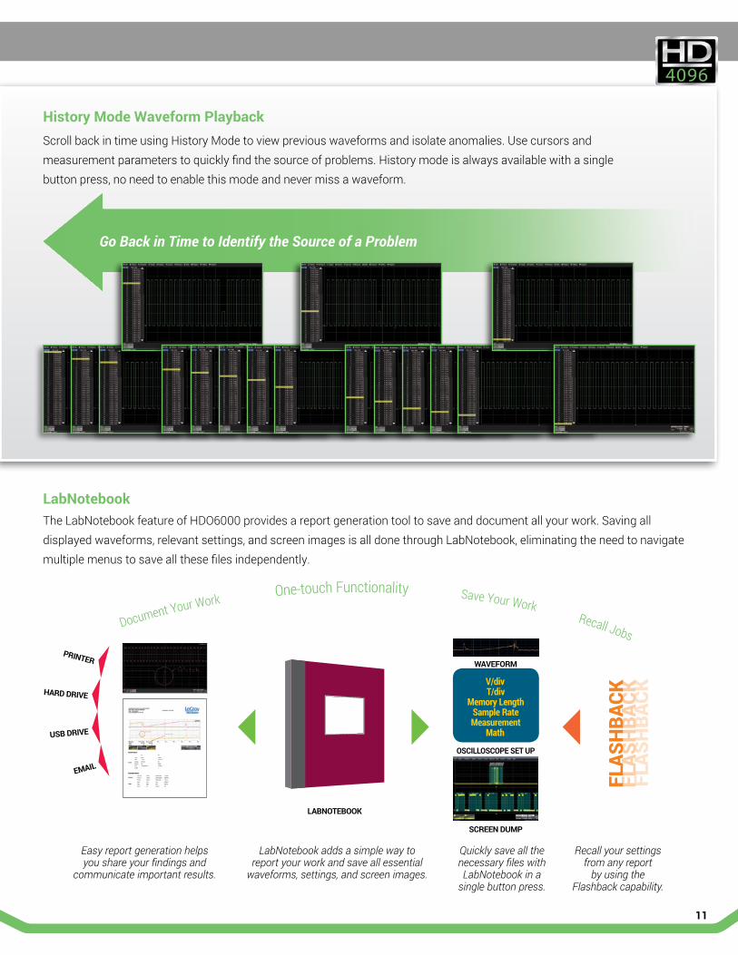
History Mode Waveform PlaybackScrollbackintimeusingHistoryModetoviewpreviouswaveformsandisolateanomalies.Usecursorsandmeasurementparameterstoquicklyfindthesourceofproblems.Historymodeisalwaysavailablewithasinglebuttonpress,noneedtoenablethismodeandnevermissawaveform.
LabNotebook TheLabNotebookfeatureofHDO6000providesareportgenerationtooltosaveanddocumentallyourwork.Savingall displayedwaveforms,relevantsettings,andscreenimagesisalldonethroughLabNotebook,eliminatingtheneedtonavigatemultiplemenustosaveallthesefilesindependently.
V/divT/div
Memory LengthSample RateMeasurement
Math
WAVEFORM
OSCILLOSCOPE SET UP
SCREEN DUMP
PRINTER
HARD DRIVE
USB DRIVE
Document Your Work One-touch Functionality Save Your Work Recall Jobs
Easy report generation helps you share your findings and
communicate important results.
LabNotebook adds a simple way to report your work and save all essential
waveforms, settings, and screen images.
Quickly save all the necessary files with LabNotebook in a
single button press.
Recall your settings from any report
by using the Flashback capability.
FLAS
HBA
CKFL
ASH
BACK
FLAS
HBA
CK
LABNOTEBOOK
Go Back in Time to Identify the Source of a Problem

12
SPECTRUM ANALYZER MODE
Simplify Analysis of FFT Power Spectrum
Getbetterinsighttothefrequencycontentofanysignalwithuseofthe SpectrumAnalyzermodeontheHDO6000.Thismodeprovidesaspectrumanalyzerstyleuserinterfacewithcontrolsforstart/stopfrequencyorcenterfrequencyandspan.Theresolutionbandwidthisautomaticallysetforbestanalysisorcanbemanuallyselected.VerticalScalecanbeselectedasdBm,dBV,dBmV,dBuV,VrmsorArmsforproperviewingandanalysiswhiletheunique peak search automatically labels spectral components and presents frequency and level in an interactive table. Utilize up to 20 markers to automati-cally identify harmonics and quickly analyze frequency content by making mea-surementsbetweenreferenceanddeltamarkers.Tomonitorhowthespectrumchangesovertime,viewthespectrogramwhichcandisplaya2Dor3Dhistoryof the frequency content.
Spectrum analyzer style controls simplify waveform analysis in the frequency domain.
Key Features
• Spectrum analyzer style controls for the oscilloscope
• Select from six vertical scales
• Automatically identify frequency peaks
• Display up to 20 markers, with interactive table readout of frequencies and levels
• Easily make measurements with reference and delta markers
• Automatically identify and mark fundamental frequency and harmonics
• Spectrogram shows how spectra changes over time in 2D or 3D views

13
POWER ANALYZER OPTION
Power Analyzer Automates Switching Device Loss Measurements
QuicklymeasureandanalyzetheoperatingcharacteristicsofpowerconversiondevicesandcircuitswiththePowerAnalyzeroption.Criticalpowerswitchingde-vicemeasurements,controlloopmodulationanalysis,andlinepowerharmonictestingareallsimplifiedwithadedicateduserinterfaceandautomaticmeasure-ments.Areasofturn-on,turn-off,andconductionlossareallidentifiedwithcolor-codedwaveformoverlaysforfasteranalysis. PowerAnalyzerprovidesquickandeasysetupofvoltageandcurrentinputsandmakesmeasurementsassimpleasthepushofabutton.Toolsareprovidedtohelp reduce sources of measurement errors and the measurement parameters providedetailsofsinglecycleoraveragedevicepowerlosses. Beyondtheadvancedpowerlossmeasurementcapabilities, thePowerAnalyzermodulationanalysis capabilities provide insight to understand control loop response tocriticaleventssuchasapowersupply’s soft start performance or step response to line and loadchanges.TheLinePowerAnalysistoolallowssimpleand quick pre-compliance testing to EN 61000-3-2.
Teledyne LeCroy has a variety of probes and probing accessories such as high common mode rejection ratio (CMRR)
differential amplifiers, differential probes, current probes, and deskew fixtures.
Key Features
• Automatic switching device measurements
• Color coded overlay to identify power losses
• Control loop and time domain response analysis
• Line power and harmonics tests to IEC 61000-3-2
• Total harmonic distortion table shows frequency contribution
• B-H Curve shows magnetic device saturation

14
PROBES
ZS Series High Impedance Active Probes ZS2500,ZS1500,ZS1000, ZS2500-QUADPAK, ZS1500-QUADPAK, ZS1000-QUADPAK
TheZSSeriesprobesprovidehighimpedanceandanextensive set of probe tips and ground accessories to handleawiderangeofprobingscenarios.Thehigh 1 MΩ inputresistanceandlow0.9pFinputcapacitancemeanthisprobeisidealforallfrequencies.TheZSSeriesprobesprovidefullsystembandwidthforallTeledyneLeCroyoscilloscopeshavingbandwidthsof1GHz andlower.
Differential Probes (200 MHz – 1.5 GHz)ZD1500,ZD1000,ZD500,ZD200
Highbandwidth,excellentcommon-moderejectionratio(CMRR)andlownoisemaketheseactivedifferentialprobes ideal for applications such as automotive development(e.g.FlexRay)andfailureanalysis,aswellaswirelessanddatacommunicationdesign.TheProBusinterfaceallowssensitivity,offsetandcommon-moderange to be displayed on the oscilloscope screen.
High Voltage Differential ProbesHVD3102,HVD3106,AP031
Lowcostactivedifferentialprobesareintendedformeasuringhighervoltages.Thedifferentialtechniquesemployedpermitmeasurementstobetakenattwopointsinacircuitwithoutreferencetotheground,allowingtheoscilloscopetobesafelygroundedwithouttheuseofopto-isolators or isolating transformers.
High Voltage Passive ProbesHVP120,PPE1.2KV,PPE2KV, PPE4KV,PPE5KV,PPE6KV
Highvoltageprobesaresuitableforawiderangeofapplicationswherehigh-voltagemeasurementsmustbemadesafelyandaccurately.Thereareseveralfixedattenuation probes covering a range from 1 kV to 6 kV and varying transient overvoltage ratings. All of these high voltage probes feature a spring loaded probe tip and a variety of standard accessories to make probing high voltagessafeandeasy.Additionally,allofthehighvoltageprobehaveaprobesensepintoautomaticallyconfiguretheoscilloscopeforusewiththeprobe.
Current ProbesCP031,CP030,AP015,CP150,CP500,DCS015
Availablecurrentprobesreachbandwidthsof100MHz,peakcurrentsof700Aandsensitivitiesof10mA/div.Usemultiple current probes to make measurements on three-phasesystemsorasinglecurrentprobewithavoltageprobetomakeinstantaneouspowermeasurements.TeledyneLeCroycurrentprobesenablethedesignandtestingofswitchingpowersupplies,motordrives,electricvehicles,anduninterruptiblepowersupplies.
The right probe is an essential tool for accurate signal capture and Teledyne LeCroy offers an extensive range of probes to meet virtually every probing need.

15
SPECIFICATIONS
HDO6034 HDO6034-MS
HDO6054 HDO6054-MS
HDO6104 HDO6104-MS
Analog - VerticalBandwidth@50Ω(-3dB) 350 MHz 500 MHz 1 GHzRiseTime(10–90%,50Ω) 1 ns typical 700 ps typical 450 ps typicalInputChannels 4Vertical Resolution 12-bits;upto15-bitswithenhancedresolution(ERES)Sensitivity 50 Ω:1mV/div–1V/div,fullyvariable
1 MΩ:1mV/div–10V/div,fullyvariableDCGainAccuracy (GainComponentofDCAccuracy)
±(0.5%)F.S,offsetat0V
BandwidthLimiters 20MHz,200MHzMaximum Input Voltage 50 Ω:5Vrms,1MΩ:400Vmax(DC+PeakAC≤10Khz)InputCoupling 50 Ω:DC,GND;1MΩ:AC,DC,GND;Input Impedance 50 Ω±2.0%;1MΩ±2.0%||15pF,Offset Range 50 Ω:1mV-4.95mV:±1.6V,5mV-9.9mV:±4V,10mV-19.8mV:±8V,20mV-1V:±10V
1 MΩ: 1mV-4.95mV:±1.6V,5mV-9.9mV:±4V,10mV-19.8mV:±8V,20mV-100mV:±16V, 102mV-198mV:±80V,200mV-1V:±160V,1.02V-10V:±400V
DCVerticalOffsetAccuracy ±(1.0%ofoffsetvalue+0.5%FS+0.02%ofmaxoffset+1mV)
Analog - AcquisitionSample Rate (Single-shot) 2.5GS/sSample Rate (Repetitive) 125GS/s,userselectableforrepetitivesignals(20ps/divto10ns/div)Record Length Standard-STD:50Mpts/ch(allchannels)
Option-L:100Mpts/ch(allchannels)Option-XL:250Mpts/ch(allchannels)
Acquisition Modes Real-time,Roll,RIS(RandomInterleavedSampling), Sequence(SegmentedMemoryupto30,000segments,60,000segments-LOption,65,000-XLoption) with1usintersegmentdead-time
TimebaseRange 20ps/div-5ks/divwithstandardmemory(upto10ks/divwith-Lmemory,25ks/divwith-XLmemory);RIS available at ≤ 10ns/div;RollModeavailableat≥100ms/divand≤5MS/s
TimebaseAccuracy ±2.5ppmfor5to40C+1.0ppm/yearfromcalibrationChannel-ChannelDeskewRange ±9xtime/div.setting,100msmax.,eachchannelExternalTimebaseReference(Input) 10MHz±25ppmat0to10dBminto50ΩExternalTimebaseReference(Output) 10MHz2.0dBm±1dBm,sinewavesynchronoustoscopetimebaseExternalClock DCto100MHz;(50Ω/1MΩ),Ext.BNCinput,
Minimumrisetimeandamplituderequirementsapplyatlowfrequencies
Analog - Acquisition ProcessingAveraging Summedaveragingto1millionsweeps;continuousaveragingto1millionsweepsEnhanced Resolution (ERES) From 12.5- to 15-bits vertical resolutionEnvelope (Extrema) Envelope,floor,orroofforupto1millionsweepsInterpolation Linear(Default)orSinx/X
Digital - Vertical and Acquisition (-MS Models Only)InputChannels 16DigitalChannelsThresholdGroupings Pod2:D15-D8,Pod1:D7-D0ThresholdSelections TTL,ECL,CMOS(2.5V,3.3V,5V),PECL,LVDSorUserDefinedMaximum Input Voltage ±30V PeakThresholdAccuracy ±(3%ofthresholdsetting+100mV)Input Dynamic Range ± 20VMinimumInputVoltageSwing 400mVInput Impedance (Flying Leads) 100 kΩ||5pFMaximum Input Frequency 250 MHzSample Rate 1.25GS/sRecord Length Standard-STD:50MS-16Channels
Optional-L:100MS-16Channels Optional-XL: 125MS-16Channels
Minimum Detectable Pulse Width 2 nsChannel-to-ChannelSkew 350 psUserDefinedThresholdRange ±10 V in 20 mV stepsUserDefinedHysteresisRange 100 mV to 1.4 V in 100 mV steps
16
SPECIFICATIONS
HDO6034 HDO6034-MS
HDO6054 HDO6054-MS
HDO6104 HDO6104-MS
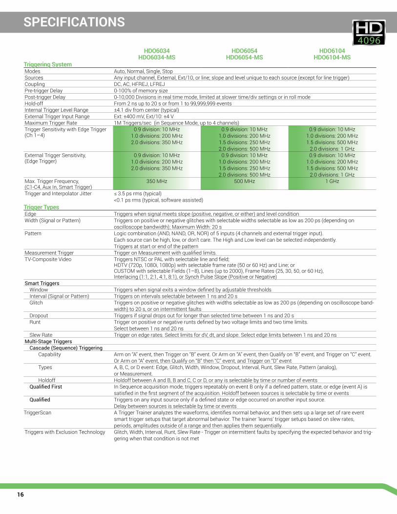
Triggering SystemModes Auto,Normal,Single,StopSources Anyinputchannel,External,Ext/10,orline;slopeandleveluniquetoeachsource(exceptforlinetrigger)Coupling DC,AC,HFREJ,LFREJPre-trigger Delay 0-100%ofmemorysizePost-trigger Delay 0-10,000Divisionsinrealtimemode,limitedatslowertime/divsettingsorinrollmodeHold-off From2nsupto20sorfrom1to99,999,999eventsInternalTriggerLevelRange ±4.1 div from center (typical)ExternalTriggerInputRange Ext:±400mV,Ext/10:±4VMaximumTriggerRate 1MTriggers/sec(inSequenceMode,upto4channels)TriggerSensitivitywithEdgeTrigger(Ch1–4)
0.9 division: 10 MHz1.0 divisions: 200 MHz2.0 divisions: 350 MHz
0.9 division: 10 MHz1.0 divisions: 200 MHz1.5 divisions: 250 MHz2.0 divisions: 500 MHz
0.9 division: 10 MHz1.0 divisions: 200 MHz1.5 divisions: 500 MHz
2.0 divisions: 1 GHzExternalTriggerSensitivity, (EdgeTrigger)
0.9 division: 10 MHz1.0 divisions: 200 MHz2.0 divisions: 350 MHz
0.9 division: 10 MHz1.0 divisions: 200 MHz1.5 divisions: 250 MHz2.0 divisions: 500 MHz
0.9 division: 10 MHz1.0 divisions: 200 MHz1.5 divisions: 500 MHz
2.0 divisions: 1 GHzMax.TriggerFrequency, (C1-C4,AuxIn,SmartTrigger)
350 MHz 500 MHz 1 GHz
TriggerandInterpolatorJitter ≤3.5psrms(typical)<0.1psrms(typical,softwareassisted)
Trigger TypesEdge Triggerswhensignalmeetsslope(positive,negative,oreither)andlevelconditionWidth (Signal or Pattern) Triggersonpositiveornegativeglitcheswithselectablewidthsselectableaslowas200ps(dependingon
oscilloscopebandwidth);MaximumWidth:20sPattern Logiccombination(AND,NAND,OR,NOR)of5inputs(4channelsandexternaltriggerinput).
Eachsourcecanbehigh,low,ordon’tcare.TheHighandLowlevelcanbeselectedindependently. Triggersatstartorendofthepattern
MeasurementTrigger TriggeronMeasurementwithqualifiedlimits.TV-CompositeVideo TriggersNTSCorPALwithselectablelineandfield;
HDTV(720p,1080i,1080p)withselectableframerate(50or60Hz)andLine;or CUSTOMwithselectableFields(1–8),Lines(upto2000),FrameRates(25,30,50,or60Hz), Interlacing(1:1,2:1,4:1,8:1),orSynchPulseSlope(PositiveorNegative)
Smart TriggersWindow TriggerswhensignalexitsawindowdefinedbyadjustablethresholdsInterval (Signal or Pattern) Triggersonintervalsselectablebetween1nsand20sGlitch Triggersonpositiveornegativeglitcheswithwidthsselectableaslowas200ps(dependingonoscilloscopeband-
width)to20s,oronintermittentfaultsDropout Triggersifsignaldropsoutforlongerthanselectedtimebetween1nsand20sRunt Triggeronpositiveornegativeruntsdefinedbytwovoltagelimitsandtwotimelimits.
Selectbetween1nsand20nsSlewRate Triggeronedgerates.SelectlimitsfordV,dt,andslope.Selectedgelimitsbetween1nsand20ns
Multi-Stage TriggersCascade (Sequence) Triggering
Capability Armon“A”event,thenTriggeron“B”event.OrArmon“A”event,thenQualifyon“B”event,andTriggeron“C”event.OrArmon“A”event,thenQualifyon“B”then“C”event,andTriggeron“D”event
Types A,B,C,orDevent:Edge,Glitch,Width,Window,Dropout,Interval,Runt,SlewRate,Pattern(analog), or Measurement.
Holdoff HoldoffbetweenAandB,BandC,CorD,oranyisselectablebytimeornumberofeventsQualified First InSequenceacquisitionmode,triggersrepeatablyoneventBonlyifadefinedpattern,state,oredge(eventA)is
satisfiedinthefirstsegmentoftheacquisition.HoldoffbetweensourcesisselectablebytimeoreventsQualified Triggersonanyinputsourceonlyifadefinedstateoredgeoccurredonanotherinputsource.
DelaybetweensourcesisselectablebytimeoreventsTriggerScan ATriggerTraineranalyzesthewaveforms,identifiesnormalbehavior,andthensetsupalargesetofrareevent
smarttriggersetupsthattargetabnormalbehavior.Thetrainer‘learns’triggersetupsbasedonslewrates, periods,amplitudesoutsideofarangeandthenappliesthemsequentially.
TriggerswithExclusionTechnology Glitch,Width,Interval,Runt,SlewRate-Triggeronintermittentfaultsbyspecifyingtheexpectedbehaviorandtrig-geringwhenthatconditionisnotmet

17
SPECIFICATIONS
HDO6034 HDO6034-MS
HDO6054 HDO6054-MS
HDO6104 HDO6104-MS
Measurement ToolsMeasurement Functionality Displayany8parameterstogetherwithstatistics,includingtheiraverage,high,low,andstandarddeviations.
Histiconsprovideafast,dynamicviewofparametersandwaveshapecharacteristics. ParameterMathallowsaddition,subtraction,multiplication,ordivisionoftwodifferentparameters. Parametergatesdefinethelocationonthesourcewaveform. Each occurrence of each parameter is measured and added to the statistics table.
Measurement Parameters Amplitude,Area,Base(Low),Cycles,Data,Delay,DeltaDelay,DutyCycle,Duration,Falltime(90–10%,80–20%,@level),Frequency,First,Last,Level@x,Maximum,Mean,Median,Minimum,Narrowbandphase,Narrowbandpower,Numberofpoints,+Overshoot,–Overshoot,Peak-to-peak,Period,Risetime(10–90%,20–80%,@level),RMS,Std.deviation,Top,Width,Median,Phase,Time@minimum(min.),Time@maximum(max.),Deltatime@level,Deltatime@levelfromtrigger,X@max.,X@min.,Cycle-CycleJitter,N-Cycle,N-Cyclewithstartselection,Frequency@level,Period@level,HalfPeriod,Width@level,TimeIntervalError@level,Setup,Hold,Skew,DutyCycle@level,DutyCycleError,Edge@lv(countsedges)
Math ToolsMath Functionality Displayupto8mathfunctiontraces(F1–F8).Theeasy-to-usegraphicalinterfacesimplifiessetupofuptotwoop-
erationsoneachfunctiontrace,andfunctiontracescanbechainedtogethertoperformmath-on-math.Math Operators Absolutevalue,Average(summed),Average(continuous),Correlation(twowaveforms),Cubicinterpolation,Deriva-
tive,Deskew(resample),Difference(–),Enhancedresolution(to15bitsvertical),Envelope,Exp(basee),Exp(base10),FFT(powerspectrum,magnitude,phase,powerdensity,real,imaginary,magnitudesquared,upto128Mptsandrectangular,VonHann,Hamming,FlatTopandBlackmanHarriswindows),Floor,Integral,Interpolate(cubic,quadratic,sinx/x),Invert(negate),Log(basee),Log(base10),Product(x),Reciprocal,Rescale(withunits),Roof,(SINx)/x,Sparse,Square,Squareroot,Sum(+),Zoom(identity).2dualoperatormathfunctionsmaybedefinedata time.
Measurement and Math IntegrationHistogramsexpandedwith19histogramparametersandupto2billionevents Trend(datalog)ofupto1millionevents Trackgraphsofallparameters Persistencehistogram,persistencetrace(mean,range,sigma)
Pass/Fail TestingTestTypes Parameterlimittesting,masktesting.
Pass/FailActionsinclude:Save,Stop,Alarm,Pulse,Hardcopy,LabNotebook
ProbesStandard Probes PP018 (5 mm) (Qty. 4)Probing System BNCandTeledyneLeCroyProBusforActivevoltage,currentanddifferentialprobes
Display SystemDisplay Size Color12.1"widescreenflatpanelTFT-ActiveMatrixwithhighresolutiontouchscreenDisplay Resolution WXGA; 1280 x 800 pixelsNumberofTraces Displayamaximumof16traces.Simultaneouslydisplaychannel,zoom,memoryandmathtracesGrid Styles Auto,Single,Dual,Quad,Octal,X-Y,Single+X-Y,Dual+X-Y,Tandem,Quattro,Twelve,SixteenWaveform Representation Sampledotsjoined,orsampledotsonly
ConnectivityEthernet Port (2)10/100/1000Base-TEthernetinterface(RJ-45connector)USBHostPorts (6)USBPortsTotal–(2)FrontUSBPortsUSBDevicePort (1)USBTMCPortGPIBPort(Optional) Supports IEEE – 488.2 (External)External Monitor Port Standard15-pinD-TypeSVGA-compatibleDB-15connector,DVIconnectorandHDMIconnectorRemoteControl ViaWindowsAutomation,orviaTeledyneLeCroyRemoteCommandSetProcessor/CPUType IntelCorei5,2.5GHz(orbetter)Processor Memory 8GBstandardOperating System Windows®EmbeddedStandard7Professional,64-bit

18
SPECIFICATIONS
HDO6034 HDO6034-MS
HDO6054 HDO6054-MS
HDO6104 HDO6104-MS
Power RequirementsVoltage 100–240VAC±10%at45–66Hz;100–120VAC±10%at380–420Hz;
AutomaticACVoltageSelection;InstallationCategory:300VCATIIPowerConsumption(Nominal) 200W/200VAMaxPowerConsumption 350W/350VA(withallPCperipheralsandactiveprobesconnectedto4channels)EnvironmentalTemperature Operating:5°Cto40°C;Non-Operating:-20°Cto60°CHumidity Operating:5%to90%relativehumidity(non-condensing)upto+31°C,Upperlimitderatesto50%relativehumidity
(non-condensing)at+40°C; Non-Operating:5%to95%relativehumidity(non-condensing)astestedperMIL-PRF-28800F
Altitude Operating:3,048m(10,000ft)maxat≤30C;Non-Operating:Upto12,192meters(40,000ft)Random Vibration Operating : 0.31 grms5Hzto500Hz,15minutesineachofthreeorthogonalaxes;
Non-Operating: 2.4 grms5Hzto500Hz,15minutesineachofthreeorthogonalaxesFunctional Shock 30 gpeak,halfsine,11mspulse,3shocks(positiveandnegative)ineachofthreeorthogonalaxes,18shockstotalPhysicalDimensions (HWD) 11.48”H x 15.72”W x 5.17”D (291.7 mm x 399.4 mm x 131.31 mm)Weight 5.86 kg (12.9 lbs)
CertificationsCECertification LowVoltageDirective2006/95/EC
EN61010-1:2010,EN61010-2-030:2010 EMCDirective2004/108/EC EN61326-1:2006,EN61326-2-1:2006
UL and cUL Listing UL61010-1(3rdEdition),UL61010-2-030(1stEdition) CAN/CSAC22.2No.61010-1-12
Warranty and Service3-yearwarranty;calibrationrecommendedannually.Optionalserviceprogramsincludeextendedwarranty,upgrades,andcalibrationservices

19
Product Description Product CodeHDO6000 Oscilloscopes350MHz,2.5GS/s,4Ch,50Mpts/Ch12-bitHD Oscilloscopewith12.1"WXGATouchDisplay
HDO6034
500MHz,2.5GS/s,4Ch,50Mpts/Ch12-bitHD Oscilloscopewith12.1"WXGATouchDisplay
HDO6054
1GHz,2.5GS/s,4Ch,50Mpts/Ch12-bitHD Oscilloscopewith12.1"WXGATouchDisplay
HDO6104
HDO6000-MS Mixed Signal Oscilloscopes350MHz2.5GS/s,4+16Ch,50Mpts/Ch12-bitHD MixedSignalOscilloscopewith12.1”WXGAColorDisplay
HDO6034-MS
500MHz2.5GS/s,4+16Ch,50Mpts/Ch12-bitHD MixedSignalOscilloscopewith12.1"WXGAColorDisplay
HDO6054-MS
1GHz2.5GS/s,4+16Ch,50Mpts/Ch12-bitHD MixedSignalOscilloscopewith12.1”WXGAColorDisplay
HDO6104-MS
Included with Standard Configurations (HDO6000 and HDO6000-MS)÷10PP018PassiveProbe(Qty.4),GettingStartedGuide,Anti-virusSoftware(TrialVersion),MicrosoftWindowsEmbeddedStandard7P64-BitLicense,CommercialNISTTraceableCalibrationwithCertificate,PowerCablefortheDestinationCountry,ProtectiveFrontCover,3-yearWarranty
Included with HDO6000-MS16ChannelDigitalLeadset,ExtraLargeGripperProbeSet(Qty.22), GroundExtenders(Qty.20),FlexibleGroundLeads(Qty.5)
Memory Options100Mpts/chmemoryOption HDO6K-L250Mpts/chMemoryOption HDO6K-XL
Hardware OptionsRemovable Hard Drive Package (includes removableharddrivekitandtwoharddrives)
HDO6K-RHD
Additional Removable Hard Drive HDO6K-RHD-02
General AccessoriesExternalGPIBAccessory USB2-GPIBSoftCarryingCase HDO6K-SOFTCASERack Mount Accessory HDO6K-RACKAccessory Pouch HDO6K-POUCH
Local Language OverlaysGerman Front Panel Overlay HDO6K-FP-GERMANFrench Front Panel Overlay HDO6K-FP-FRENCHItalian Front Panel Overlay HDO6K-FP-ITALIANSpanish Front Panel Overlay HDO6K-FP-SPANISHJapaneseFrontPanelOverlay HDO6K-FP-JAPANESEKorean Front Panel Overlay HDO6K-FP-KOREANChinese(Tr)FrontPanelOverlay HDO6K-FP-CHNES-TRChinese(Simp)FrontPanelOverlay HDO6K-FP-CHNES-SIRussian Front Panel Overlay HDO6K-FP-RUSSIAN
Software OptionsElectricalTelecomMaskTestPackage HDO6K-ET-PMTPowerAnalysisOption HDO6K-PWRDFP2 Digital Filter Option HDO6K-DFP2Serial Data Mask Option HDO6K-SDMClockandClock-DataTimingJitterAnalysisPackage HDO6K-JITKITDeveloper’sToolKitOption HDO6K-XDEVEMCPulseParameterSoftwarePackage HDO6K-EMC
ORDERING INFORMATION
Product Description Product CodeSerial Data OptionsARINC429SymbolicDecodeOption HDO6K-ARINC429busDSymbolicAudiobusTriggerandDecodeOptionfor I2S,LJ,RJ,andTDM
HDO6K-AudiobusTD
AudiobusTrigger,Decode,AndGraphOption HDO6K-AudiobusTDGCANTDTriggerandDecodeOption HDO6K-CANbusTDCANBusTrigger,Decode& Measure/GraphOption
HDO6K-CANbusTDM
D-PHYDecodeOption HDO6K-DPHYbusDDigRF 3G Decode Option HDO6K-DigRF3Gbus DDigRF v4 Decode Option HDO6K-DigRFv4bus DENETDecodeOption HDO6K-ENETbusDFlexRayTriggerandDecode Option HDO6K-FlexRaybusTDFlexRayBusTrigger,Decode,and PhysicalLayerTestOption
HDO6K-FlexRaybusTDP
I2C,SPIandUARTTriggerandDecodeOption HDO6K-EMBI2CBusTriggerandDecodeOption HDO6K-I2CbusTDLINTriggerandDecodeOption HDO6K-LINbusTDManchester Decode Option HDO6K-Manchesterbus DMIL-STD-1553TriggerandDecodeOption HDO6K-1553TDNRZDecodeOption HDO6K-NRZbusDSENTDecodeOption HDO6K-SENTbusDSerialDebugToolkit-MeasureAnalyzeGraph HDO6K-ProtoBusMagSPIBusTriggerandDecodeOption HDO6K-SPIbusTDUARTandRS-232TriggerandDecodeOption HDO6K-UART-RS232busTDUSB2.0TriggerandDecodeOption HDO6K-USB2busTDUSB2-HSICDecodeOption HDO6K-USB2-HSICbusDVehicleBusAnalyzerBundle-IncludesCANTDM,CANSymbolic,FlexRayTDP,LINTD and Protobus MAG.
HDO6K-VBA
Probes and Amplifiers500MHzPassiveProbe,10:1,10MΩ PP018Setof4ZS1500,1.5GHz,0.9pF,1MΩ High Impedance Active Probe
ZS1500-QUADPAK
Setof4ZS1000,1GHz,0.9pF,1MΩ High Impedance Active Probe
ZS1000-QUADPAK
200MHz,3.5pF,1MΩ Active Differential Probe ZD200500MHz,1.0pF,1MΩ Active Differential Probe ZD5001GHz,1.0pF,1MΩ Active Differential Probe ZD10001.5GHz,1.0pF,1MΩ Active Differential Probe ZD15001,500V,25MHzHigh-VoltageDifferentialProbe HVD30121,500V,120MHzHigh-VoltageDifferentialProbe HVD31061Ch,100MHzDifferentialAmplifier withPrecisionVoltageSource
DA1855A
100:1or10:1Selectable,250MHzPassiveDiff.ProbePair DXC100A30A;100MHzCurrentProbe–AC/DC;30Arms; 50 Apeak Pulse CP03130A;50MHzCurrentProbe–AC/DC;30 Arms; 50 Apeak Pulse CP03030A;50MHzCurrentProbe– AC/DC;30 Arms; 50 Apeak Pulse AP015150A;10MHzCurrentProbe–AC/DC;150Arms; 500 Apeak Pulse CP150500A;2MHzCurrentProbe–AC/DC;500Arms; 700 Apeak Pulse CP500DeskewCalibrationSourceforCP031,CP030andAP015 DCS015100:1400MHz50MΩ1kVHigh-voltageProbe HVP12010:1/100:1200/300MHz,50MΩ High-voltage Probe 600V/1,2kVMax.Volt.DC
PPE1.2KV
100:1 400 MHz 50 MΩ 2 kV High-voltage Probe PPE2KV100:1 400 MHz 50 MΩ 4 kV High-voltage Probe PPE4KV1000:1 400 MHz 50 MΩ 5 kV High-voltage Probe PPE5KV1000:1 400 MHz 50 MΩ 6 kV High-voltage Probe PPE6KV

©2012TeledyneLeCroy,Inc.Allrightsreserved.Specifications,prices,availability,anddeliverysubjecttochangewithoutnotice. Product or brand names are trademarks or requested trademarks of their respective holders.
hdo6k-ds-12feb15
Local sales offices are located throughout the world. Visit our website to find the most convenient location.
1-800-5-LeCroy teledynelecroy.com
Customer Service TeledyneLeCroyoscilloscopesandprobesaredesigned,built,andtestedtoensurehighreliability.Intheunlikelyeventyouexperiencedifficulties, ourdigitaloscilloscopesarefullywarrantedforthreeyearsandourprobesarewarrantedforoneyear.Thiswarrantyincludes:
• No charge for return shipping
• Long-term 7-year support
•Upgradetolatestsoftwareatnocharge
Top Related