


Languages
Pages
Legal


HC - 4 MK2 HELIUM COMPRESSOR
TECHNICAL MANUAL
APD CRYOGENICS INC1833 Vultee Street
Allentown, PA 18103
flo)'" / J/C /;v1 il-
II) //1/ 1 /; ;) (/ J l - / Y/;' ,r//1' ' .. (,,;;,.) ,~. ;'
~' l' '/1 f ·: .",/ IN!C, ,
j)'O /1 Y/j/, ,,,. / 'J<:1
REVISION A: August 1995 261803A

TABLE OF CONTENTS
INTRODUCTION 3-1Helium Compressor Model HC-4 MK2 3-1
PRINCIPLES OF OPERATION 3-1. .
DESCRiPTION 3-3Components 3-3
SPECiFiCATIONS 3-8Electrical Characteristics 3-8Cooling Requirements 3-8Helium Gas Pressures 3-9Compressor Lubricant. 3-9Compressor Weight 3-9Mounting Position 3-9Installation Kit. 3-9Dimensions 3-10
MAINTENANCE 3-11Adsorber Replacement 3-12
Adsorber Removal 3-12Adsorber Installation 3-13Used Adsorber Venting and Disposal 3-14
Venting Procedure to Vent to Atmospheric Pressure 3-14Gas Cleanup 3-15
TROUBLESHOOTING 3-18Automatic Shutdown 3-18Measure Resistance Values of Components 3-21Compressor Motor 3-21
Winding Continuity, Grounding and Resistance 3-22Current Measurement 3-23
PARTS 3-25Ordering 3-25Parts Identification and Numbers 3-27
iii - i

ILLUSTRATIONS LIST
Fig. 3.1Fig. 3.2Fig. 3.3Fig. 3.4Fig. 3.5Fig. 3.6Fig. 3.7Fig. 3.8Fig. 3.9Fig. 3.10
RLE/dmk261803A.DOC
HC-4MK2 Flow Diagram 3-2Parts Identification 3-4Parts Identification 3-6Electrical Chassis Parts Identification 3-7HC-4 MK2 Outline Dimensions 3-10HC-4 MK2 Wiring Diagram 3-19HC-4 MK2 Electrical Schematic 3-20Compressor Terminals 3-23Parts Identification 3-26Parts Identification 3-28
iii - ii

INTRODUCTION
Helium Compressor Model HC-4 MK2
The HC-4 MK2 Compressor is a single-stage, water-cooled, rotary compressor designed todeliver high-pressure, oil-free, helium gas to cryogenic refrigerators. An expander cableconnected to the compressor supplies electrical power to the expander. Self-sealing couplingsallow for easy connection to and disconnection from the rest of the closed-cycle cryogenicrefrigeration system.
PRINCIPLES OF OPERATION
The compressor continuously draws low-pressure helium from the system return line. Itcompresses, cools and cleans the gas, then delivers it through the system supply line to theexpander. See Fig. 3.1.
When gas leaves the compressor, it contains heat and compressor lubricant. Both must beremoved. From the compressor, the hot gas with its entrained oil flows over the motor winding,where the gas loses some of its suspended oil, then out of the shell and through one circuit ofa three-circuit heat exchanger, where the gas is cooled. Next, the gas passes through the oilseparator and the adsorber for oil and moisture removal. From the adsorber, the highpressure gas is piped to the expander.
Through the system gas return line, low-pressure gas from the expander flows into thecompressor.
A gas line containing an internal bypass valve connects the high-pressure line to the lowpressure line. The bypass valve will open to prevent overloading the motor when the systemgas lines are not connected to the compressor.
Oil is separated from the gas in three stages. The first stage is by precipitation when the gaspasses over the motor windings. The second-stage is the oil separator whose element collectsoil mist from the gas, agglomerates it and returns the oil to the compressor. The third stage isthe adsorber which removes any remaining oil the gas is carrying.
Oil collected in the separator flows back to the compressor through a capillary tube. Thedifferential gas pressure across the system is the moving force, and the capillary size limits theamount of gas bypassed. The small amount of oil collected in the adsorber remains there andis removed only by replacing the adsorber.
Oil in the compressor housing also collects heat. The shell-wrapped heat exchanger removesheat from the compressor motor and the warm oil by direct conduction through the compressorshell. Gas pressure pushes oil through the heat exchanger's outer tubes which cool the warmoil from the compressor. This cooled oil is then reinjected into the gas return line, whichreturns the oil to the compressor to reabsorb heat and lubricate the compressor.
3-1

PRINCIPLES OF OPERATION
1. Oil Line Filter2. Oil Differential Pressure Switch3. Oil Injection Orifice4. Heat Exchanger5. Compressor6. Oil Separator7. Oil Capillary Filter8. Oil Capillary9. Adsorber10. Internal Bypass Valve
11. Surge Bottle12. Pressure Gauge13. Gas Equalization Solenoid Valve14. Gas Supply Coupling15. Gas Return Coupling16. Water Supply Fitting17. Water Return Fitting18. Pressure Relief Valve19. Temperature Overload Switch20. Water Solenoid Valve
Fig. 3.1 HC-4 MK2 Flow Diagram
3-2
DESCRIPTION
The components of the HC-4 MK2 Compressor are identified schematically in Fig. 3.1. Figures3.2,3.3 and 3.4 identify the parts pictorially. Features and functions of individual componentsare described in the following paragraphs.
Components
Gas Supply and Return Couplings -- Both are self-sealing bulkhead couplings and are thepoints of connection on the rear panel for the rest of the system.
Water Supply and Return Fittings -- Both fittings are compression-type bulkhead fittingsmounted on the rear panel, for 3/8" tubing.
Compressor Power Cord -- Terminating with a 3-prong plug, this power cord supplieselectrical power to the compressor.
Elapsed Time Meter -- The battery-operated LCD elapsed time meter shows thecompressor's cumulative runining time in hours up to a total of 99,999 hours.
WARNING
THE ELAPSED TIME METER CONTAINS A LITHIUM BATTERY.DO NOT REMOVE THE BATTERY. DO NOT RECHARGE,DISASSEMBLE, MUTILATE, WET OR DISPOSE OF THE METERIN FIRE.
Power Switch -- This on/ off switch starts and stops the compressor. The switch lights toindicate that power is on to the compressor.
Pressure Gauge -- A pressure gauge indicates gas supply pressure. When the compressoris not running, the gauge shows the equalization pressure.
Expander (Displacer) Receptacle and Expander Cable -- A 28-socket receptacle mountedon the rear panel and an expander cable supply electrical power from the compressor to theexpander.
Accessory Receptacle and Optional Cables -- The accessory receptacle mounted on the.rear panel is a 14-socket connector for supplying auxiliary power or remote on/ off control. Theremote on/ off and auxiliary power cables are available as options.
Circuit Breaker -- A panel mounted circuit breaker in the main power supply protects thecompressor module from electrical overload.
Fuses -- Two 0.6 ampere fuses in the expander circuit and one 0.6 ampere fuse in theprimary of the control transformer are accessible in the rear panel. Two 5 ampere fuses in theauxiliary power circuit (from the accessory receptacle) are located in the electrical chassis.
3-3
DESCRIPTION
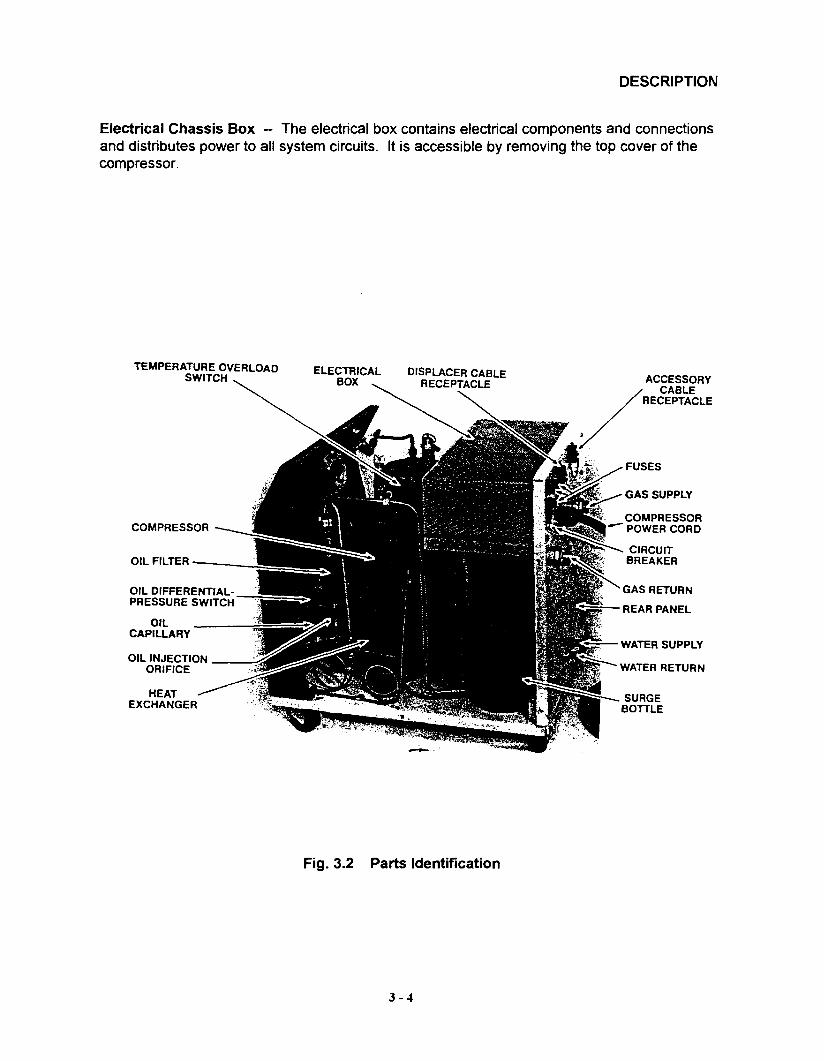
Electrical Chassis Box -- The electrical box contains electrical components and connectionsand distributes power to all system circuits. It is accessible by removing the top cover of thecompressor.
TEMPERATURE OVERLOADSWITCH
OIL DIFFERENTIALPRESSURE SWITCH
ELECTRICALBOX
CIRCUITBREAKER
REAR PANEL
Fig. 3.2 Parts Identification
3-4

DESCRIPTION
Compressor -- The rotary, positive displacement compressor is hermetically sealed.Electrical connections to the motor are made at terminals under a protective cover on top ofthe housing.
The lubricant is a synthetic oil put in the compressor at the factory. Thereafter, oil is notchanged or added. The oil fill fitting on the top of the compressor housing must not beopened.
Heat Exchanger -- The heat exchanger consists of three coils wrapped around thecompressor. One cools helium, another cools the compressor shell and another cools oil inthe oH injection circuit. This circuit cools oil that has absorbed heat from the compressor andreinjects the cooled oil, which continues to absorb heat from the compressor.
Temperature Overload Switch -- Installed under the electrical terminal box cover on top ofthe compressor, this switch senses compressor temperature through contact with the housing.The switch opens the control circuit at a predetermined temperature and resets automaticallyupon cooling.
Gas Equalization Solenoid Valve -- This solenoid valve opens when the compressor isstopped. The valve allows the helium gas pressure across the compressor to equalize, toprevent oil from being blown out of the compressor into the low-pressure gas line.
Oil Separator -- The bottom of the oil separator serves as a sump. A retainer plate abovethe sump supports fibrous material that acts as the separating agent. Entrained oil coalesceson it, forming large droplets which drain into the sump. This unit needs no servicing orreplacement.
Oil Capillary -- The capillary returns oil collected in the separator sump to the low-pressureside of the compressor for recycling.
Adsorber -- The adsorber removes any oil and moisture the gas is carrying which did notdrop out in the separator. This vessel contains activated charcoal for oil adsorption. Theadsorber has a finite life and must be replaced every 10,000 operating hours. I
Pressure Relief Valve -- The relief valve prevents the compressor from operating at anunsafe pressure.
Oil Filters -- There are two oil filters. One filter in the oil separator drain line protects thereturn oil capillary. The other filter in the oil injection circuit protects the compressor.
Oil Injection Orifice -- This orifice is installed downstream of the oil filter in the oil injectionline and controls the flow rate of oil into the compresor's gas return line.
Surge Bottle -- The surge bottle located in the return gas line dampens the pressurepUlsations.
3-5
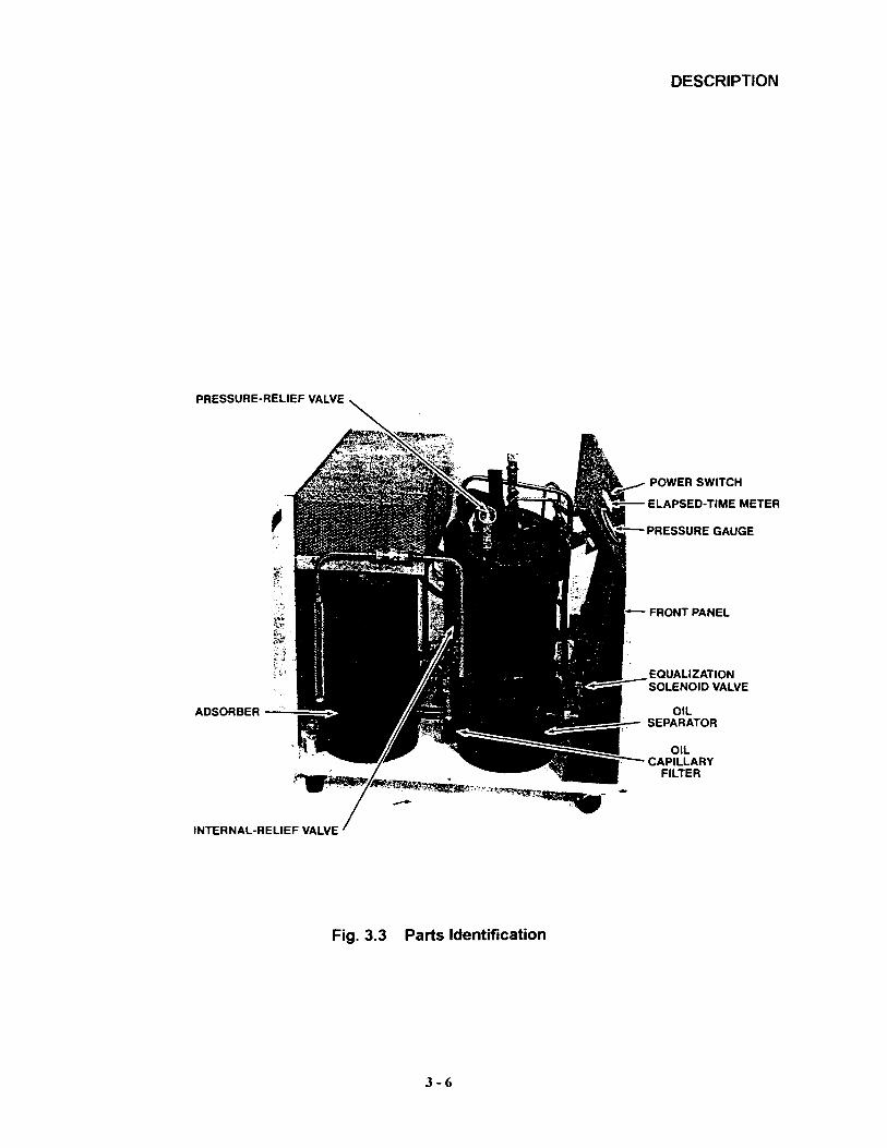
PRESSURE-RELIEF VALVE
ADSORBER -.:-:::=
INTERNAL-RELIEF VALVE
F o 3 3 Parts IdentificationIg..
3-6
DESCRIPTION
POWER SWITCH
.- ELAPSED-TIME METER
- PRESSURE GAUGE
- FRONT PANEL
EQUALIZATION~SOLENOID VALVE

./
DESCRIPTION
Oil Differential Pressure Switch -- This switch shuts down the compressor if oil injection flowis too low or too warm for proper operation.
Internal Bypass (Relief) Valve -- The internal bypass valve opens to allow the compressor tobe run when the system gas lines are disconnected, to avoid overloading the motor.
Transformer -- Some 50 Hz applications include an externally-mounted transformer on therear panel of the compressor. See Specifications.
Water Solenoid Valve -- This normally closed solenoid valve opens when the compressorstarts to allow cooling water to flow.
MOTOR
RELAY
+
FUSES CIRCUIT DISPLACER TIME START ACCESSORY RUN START(3) BREAKER RECEPTACLE DELAY RELAY RECEPTACLE CAPACITOR CAPACITOR
RELAY
Fig. 3.4 Electrical Chassis Parts Identification
3-7
SPECIFICATIONS
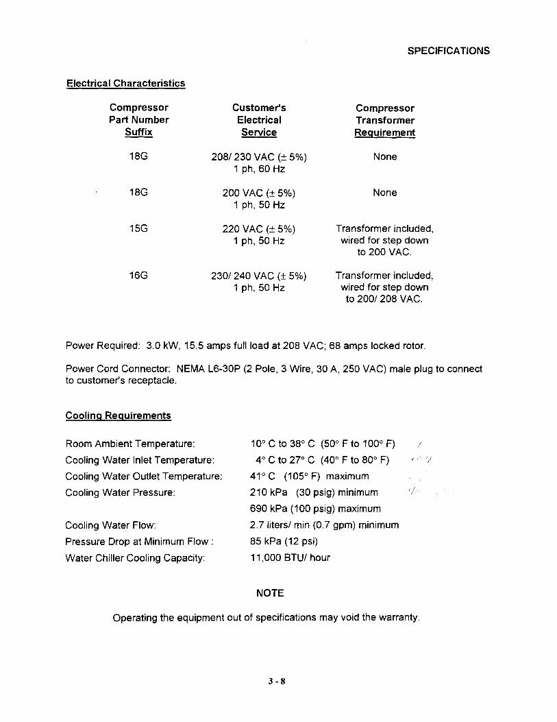
Electrical Characteristics
Compressor Customer's CompressorPart Number Electrical Transformer
Suffix Service Requirement
18G 208/230 VAC (± 5%) None1 ph, 60 Hz
18G 200 VAC (± 5%) None1 ph, 50 Hz
15G 220 VAC (± 5%) Transformer included,1 ph, 50 Hz wired for step down
to 200 VAC.
16G 230/240 VAC (± 5%) Transformer included,1 ph, 50 Hz wired for step down
to 200/208 VAC.
Power Required: 3.0 kW, 15.5 amps full load at 208 VAC; 68 amps locked rotor.
Power Cord Connector: NEMA L6-30P (2 Pole, 3 Wire, 30 A, 250 VAC) male plug to connectto customer's receptacle.
Cooling Requirements
Room Ambient Temperature:
Cooling Water Inlet Temperature:
Cooling Water Outlet Temperature:
Cooling Water Pressure:
Cooling Water Flow:
Pressure Drop at Minimum Flow:
Water Chiller Cooling Capacity:
10° C to 38° C (50° F to 100° F)
4° C to 27° C (40° F to 80° F)
41° C (105° F) maximum
210 kPa (30 psig) minimum
690 kPa (100 psig) maximum
2.7litersl min (0.7 gpm) minimum
85 kPa (12 psi)
11,000 BTUI hour
NOTE
Operating the equipment out of specifications may void the warranty.
3-8
SPECIFICATIONS
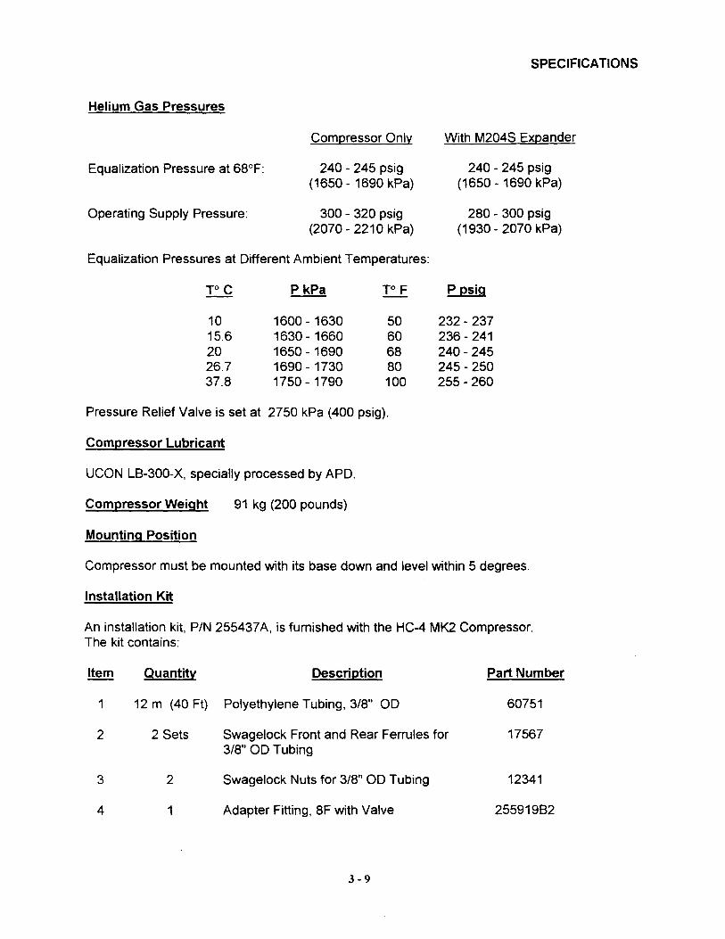
Helium Gas Pressures
Equalization Pressure at 68°F:
Operating Supply Pressure:
Compressor Only
240 - 245 psig(1650 - 1690 kPa)
300 - 320 psig(2070 - 2210 kPa)
With M204S Expander
240 - 245 psig(1650 - 1690 kPa)
280 - 300 psig(1930 - 2070 kPa)
Equalization Pressures at Different Ambient Temperatures:
roc P kPa To F P psig
10 1600 - 1630 50 232 - 23715.6 1630 - 1660 60 236 - 24120 1650 - 1690 68 240 - 24526.7 1690 - 1730 80 245 - 25037.8 1750 - 1790 100 255 - 260
Pressure Relief Valve is set at 2750 kPa (400 psig).
Compressor Lubricant
UCON L8-300-X, specially processed by APD.
Compressor Weight
Mounting Position
91 kg (200 pounds)
Compressor must be mounted with its base down and level within 5 degrees.
Installation Kit
An installation kit, PIN 255437A, is furnished with the HC-4 MK2 Compressor.The kit contains:
Item Quantity Description Part Number
1 12 m (40 Ft) Polyethylene Tubing, 3/8" 00 60751
2 2 Sets Swagelock Front and Rear Ferrules for 175673/8" 00 Tubing
3 2 Swagelock Nuts for 3/8" 00 Tubing 12341
4 1 Adapter Fitting, 8F with Valve 25591982
3-9
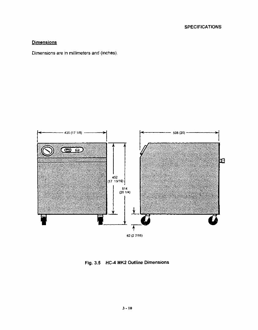
Dimensions
Dimensions are in millimeters and (inches).
IAI( 435 (17 1/8) ~I-..,.---.-
~Ai:~
452(17 13/16)
514(201/4)
SPECIFICATIONS
508 (20) ------..~I
Fig. 3.5
62 (2 7/16)
HC-4 MK2 Outline Dimensions
3 - 10

MAINTENANCE
WARNING
DISCONNECT GAS LINES ONLY WHEN THE COMPRESSOR ISSTOPPED. DISCONNECTING THE EXPANDER WHILE IT IS COLDMAY CREATE EXCESSIVELY HIGH INTERNAL PRESSURE ASTHE GAS WARMS. MATERIAL FAILURE AND UNCONTROLLEDPRESSURE RELEASE CAN CAUSE INJURY TO PERSONNELIN THE WORK AREA.
WARNING
THE COMPRESSOR IS CHARGED WITH HELIUM GAS. VENTTHE COMPRESSOR TO ATMOSPHERIC PRESSURE BEFOREDISASSEMBLY, EXCEPT WHEN DISCONNECTING ADSORBEROR GAS LINES. UNCONTROLLED PRESSURE RELEASE CANCAUSE INJURY TO PERSONNEL IN THE WORK AREA.
WARNING
NEVER USE COMPRESSED GAS FROM A CYLINDER WITHOUTA PROPER REGULATOR. OVERPRESSURIZATION CAN CAUSEPERSONAL INJURY IF THE SYSTEM EQUIPMENT RUPTURES.
WARNING
DURING OPERATION, SOME SURFACES UNDER THECOMPRESSOR'S COVER BECOME HOT. AVOID INJURY FROMBURNS BY ALLOWING THE COMPRESSOR TO COOL FOR 1/2HOUR AFTER SHUTDOWN BEFORE REMOVING THE COVERFOR MAINTENANCE.
WARNING
WHEN HANDLING PRESSURIZED GAS LINES AND OTHERPRESSURIZED EQUIPMENT, ALWAYS WEAR EYE PROTECTION.
WARNING
NEVER APPLY HEAT TO A PRESSURIZED GAS LINE OR OTHERPRESSURIZED COMPONENTS.
3 -11
Adsorber Replacement
MAINTENANCE
CAUTION
MODIFICATION TO EQUIPMENT WITHOUT THE CONSENT OFTHE MANUFACTURER WILL VOID THE WARRANTY.
CAUTION
FOLLOW CHARGING AND VENTING PROCEDURE TO PREVENTREVERSED FLOW OF SYSTEM GAS. REVERSED FLOW CANRESULT IN CONTAMINATION OF THE SYSTEM WITH THECOMPRESSOR OIL.
CAUTION
REPEATEDLY CHARGING THE SYSTEM WITH HELIUM GASRATHER THAN LOCATING AND REPAIRING GAS LEAKS MAYCAUSE A MALFUNCTION. IMPURITIES ARE INTRODUCED AT ANABNORMAL RATE AND MAY FREEZE IN THE EXPANDER.
CAUTION
CHECK THE CONDITION OF THE GASKET SEAL ON THE MALEHALF OF EACH AEROQUIP COUPLING. BE SURE THE GASKETSEAL IS IN PLACE AND THE SEALING SURFACES ON BOTH THEMALE AND FEMALE HALVES ARE CLEAN BEFORE CONNECTING.REPLACE THE GASKET SEAL IF IT IS DAMAGED OR MISSING.
CAUTION
DO NOT ALLOW AIR TO GET INTO THE SYSTEM. MOISTUREFROM THE ATMOSPHERE CAN SERIOUSLY DEGRADEEXPANDER PERFORMANCE.
/3,n; T, ! i
The adsorber must be replaced every 10,000 operating hours. The used adsorber has nosalvage or repair value. Venting of the compressor is not required when replacing theadsorber, because the couplings are self-sealing.
Adsorber Removal
1. Stop the compressor and disconnect the power to the compressor.
2. Disconnect the supply gas line from the supply coupling on the compressor. Screw a dustplug into the disconnected gas line coupling.
3 -12
MAINTENANCE
NOTE
Always hold the stationary nut on the gas line coupling with onewrench while turning the moveable coupling nut with the other wrench.
3. Remove the compressor's cover.
NOTE
Trace the outline of the adsorber on the compressor base to helplocate the proper position of the new adsorber.
4. Disconnect the self-sealing coupling on the tube from the oil separator to the inlet sideof the adsorber.
5. Elevate the compressor to gain access underneath the bottom panel. Use a 9/16"wrench to remove the 3/8" cap screw and lock washer holding the adsorber to the base.
CAUTION
DO NOT TIP THE COMPRESSOR GREATER THAN 5 DEGREES,TO AVOID FLOWING OIL INTO UNWANTED PLACES ANDCAUSING A NUISANCE SHUTDOWN.
6. Remove the lock nut and nylon washer on the supply coupling on the rear panel.
7. Pull the adsorber back until the supply coupling clears the rear panel. Remove theadsorber. Remove the lock washer from the Aeroquip supply coupling. Retain allhardware to use with the new adsorber.
WARNING
THE ADSORBER IS CHARGED WITH HELIUM GAS. FOLLOWTHE ADSORBER VENTING PROCEDURE FOR SAFE DISPOSALOF THE USED ADSORBER.
Adsorber Installation
1. Remove the caps from the gas lines of the new adsorber. Do not vent the newadsorber.
2. Position the adsorber on the base within the traced line and insert the supply couplingthrough the rear panel. Be sure the lock washer is installed on the coupling prior toinserting it through the rear panel.
3 -13
MAINTENANCE
3. Apply Locktite 242 to the threads of the cap screw used to fasten the adsorber to thebase. Install and tighten this cap screw and lock washer. Torque the cap screw to3.5 kgf m (25 ft. Ibs.). Lower the elevated compressor to the floor.
4. Install the nylon washer and the locknut on the supply coupling. Torque the locknut to5.5 kgf m (40 ft. Ibs.).
5. Connect the adsorber's self-sealing coupling on its inlet side to the oil separator's outletcoupling. With wrenches, torque the size 4 Aeroquip coupling to 1.4 to 2 kgf m (10 to15 ft. Ibs.).
6. Reconnect the supply gas line to the supply coupling on the compressor. Torque thecoupling to 4.85 ± 0.7 kgf m (35 ± 5 ft. Ibs.).
7. Leak check all Aeroquip couplings just completed. See Leak Checking in theMaintenance section of the System Manual.
8. Check the equalization pressure. See Specifications in this manual.
9. Reinstall the compressor's cover.
This completes the procedure for replacing an adsorber.
Used Adsorber Venting and Disposal
For safe disposal of the used adsorber:
1. A venting adapter fitting is included with the new adsorber. Attach it to one of the selfsealing couplings on the used adsorber. Vent the used adsorber to atmosphericpressure.
2. Discard the used adsorber and the adapter fitting.
Venting Procedure to Vent to Atmospheric Pressure
This procedure includes disconnecting the adsorber to prevent venting it.
1. Stop the compressor and disconnect the power to the compressor.
2. Disconnect both the supply and return gas lines from the couplings on the compressor.Screw dust plugs into the disconnected gas line couplings.
3. Remove the compressor's cover.
4. With wrenches, disconnect the Aeroquip coupling in the supply line between the oilseparator and the inlet side of the adsorber. This keeps the adsorber pressurized.
3 -14
MAINTENANCE
5. Locate adapter fitting PIN 257246C2. Also locate adapter fitting PIN SK8217A2 and besure its valve is closed. Move the part of the supply line fastened to the adsorber out ofthe way. Connect the adapter fittings to the female Aeroquip coupling on the supply linefrom the oil separator.
6. Slowly open the valve on the adapter fitting. Vent the system to atmospheric pressure.Close the valve on the adapter fitting.
7. Remove the adapter fittings.
8. Perform the required maintenance.
NOTE
Do not reconnect the adsorber if the compressor has been vented toatmospheric pressure.
This completes the procedure to vent the compressor to atmospheric pressure.
Gas Cleanup
Gas cleanup is required if the compressor's interior has been opened to the atmosphereor the equalization pressure is 140 kPa (20 psig) or lower. Gas cleanup is performedwith the compressor disconnected from the other system components. The adsorbermust be disconnected unless it also has been opened to the atmosphere or its chargepressure is less than 140 kPa (20 psig).
NOTE
If the compressor's interior has been exposed to the atmospherefor an extended period, gas cleanup may not suffice to guaranteesystem gas purity and adsorber replacement will be required.
1. Disconnect the gas lines from the compressor. Screw dust plugs into the disconnectedgas line couplings.
2. Locate two adapter fittings PIN 25591982. 8e sure their valves are closed. Attach themto the supply and return Aeroquip couplings on the compressor.
NOTE
If the adsorber has been disconnected, connect adapter fittingsPIN 257246C2 and PIN SK8217A2 to the supply line from the oilseparator, for venting the compressor during this procedure.
3. Connect a charge line to the pressure regulator of a helium gas cylinder containing99.995% pure helium gas with a dew point less than -50 0 C (-580 F) at 2065 kPa(300 psig). Adjust the gas cylinder pressure regulator to 35 kPa (5 psig).
3 -15
MAINTENANCE
4. While connecting the charge line to the adapter fitting on the compressor's returncoupling, thoroughly purge the charge line from the regulator. It is important to remove allair contaminants to prevent them from entering the system.
5. Adjust the pressure regulator to 1520 kPa (220 psig). Open the valve on the adapterfitting and charge the compressor to 1520 kPa (220 psig). If the adsorber is connected,increase the charge pressure to 1690 kPa (245 psig).
6. Close the valve on the adapter fitting used for charging.
7. Run the compressor for at least 30 minutes to heat the oil to operating temperature. Stopthe compressor.
8. Adjust the pressure regulator to 690 kPa (100 psig).
9. Open the vent valve on the supply coupling of the compressor. Watch the compressor'spressure gauge. When the pressure falls to 35 to 70 kPa (5 to 10 psig), close the ventvalve. Open the charge valve to build the pressure back up to 690 kPa (100 psig).Close the charge valve.
10. Repeat Step 9 five (5) times.
11. Adjust the pressure regulator to the equalization pressure of the system. SeeSpecifications.
12. Open the valve on the adapter fitting and charge the compressor to the equalizationpressure. Close the charge valve on the adapter fitting. Start the compressor.
13. After running 30 to 45 seconds, stop the compressor. Open the vent valve and vent thecompressor to 35 to 70 kPa (5 to 10 psig). Close the vent valve.
14. Repeat Steps 12 and 13 five (5) times; then go to Step 15.
15. Open the charge valve on the adapter fitting. Charge the compressor to the equalizationpressure. See Specifications in this manual. Close the charge valve.
16. Allow the compressor to cool. Read the pressure gauge with the compressor at 200 C(68 0 F). Adjust the equalization pressure by charging or venting to conform to theSpecifications.
17. Close the gas cylinder valve and adjust the pressure regulator to zero psig.
18. Disconnect the charge line from the adapter fitting. Store the charge line to keep it clean.
19. Remove both adapter fittings.
3 -16
MAINTENANCE
NOTE
Reconnect the adsorber if it was disconnected prior to gas cleanup.Torque the Aeroquip coupling to 1.4 to 2 kgf m (10 to 15 ft. Ibs.).
20. If other components need cleaning, refer to the procedure in their manuals. Otherwise,reconnect the supply and return gas lines. Torque the couplingsto 4.85 ±0.7 kgf m (35 ± 5 ft. Ibs.).
21. Leak check the Aeroquip couplings. See Leak Checking in the System manual.
This completes the gas clean-up procedure for the compressor.
3 - 17
TROUBLESHOOTING
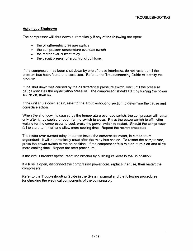
Automatic Shutdown
The compressor will shut down automatically if any of the following are open:
• the oil differential pressure switch• the compressor temperature overload switch• the motor over-current relay• the circuit breaker or a control circuit fuse.
If the compressor has been shut down by one of these interlocks, do not restart until theproblem has been found and corrected. Refer to the Troubleshooting Guide to identify theproblem.
If the shut down was caused by the oil differential pressure switch, wait until the pressuregauge indicates the equalization pressure. The compressor should start by turning the powerswitch off, then on.
If the unit shuts down again, refer to the Troubleshooting section to determine the cause andcorrective action.
When the shut down is caused by the temperature overload switch, the compressor will restartonly after it has cooled enough for the switch to close. Press the power switch to off. Afterwaiting for the compressor to cool, press the power switch to restart. Should the compressorfail to start, turn it off and allow more cooling time. Repeat the restart procedure.
The motor over-current relay, mounted inside the compressor motor, is temperaturedependent. It will automatically reset after the relay has cooled. To restart the compressor,press the power switch to the on position. If the compressor fails to start, turn it off and allowmore cooling time. Repeat the start procedure.
If the circuit breaker opens, reset the breaker by pushing its lever to the up position.
If a fuse is open, disconnect the compressor power cord, replace the fuse, then restart thecompressor.
Refer to the Troubleshooting Guide in the System manual and the following proceduresfor checking the electrical components of the compressor.
3 -18
TROUBLESHOOTING
-----~fMR
c •.
Cl~..CT
U'f'.7S...fJ.
s... .1
, I
m:"G 1C>
n .:, .4
r:-9R.
r-.L-.....~_"'....J''C.~-t----_...L_....JuHE-
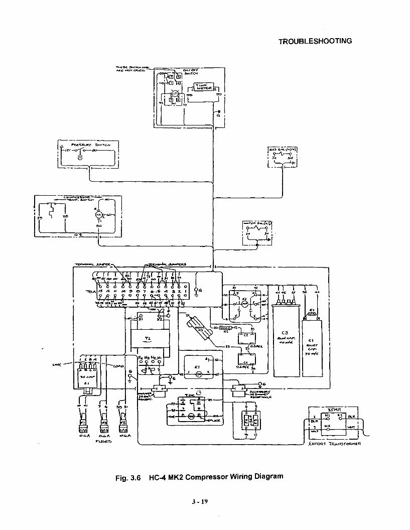
Fig. 3.6 HC-4 MK2 Compressor Wiring Diagram
3 -19
rr~tPTROUBLESHOOTING
, ')
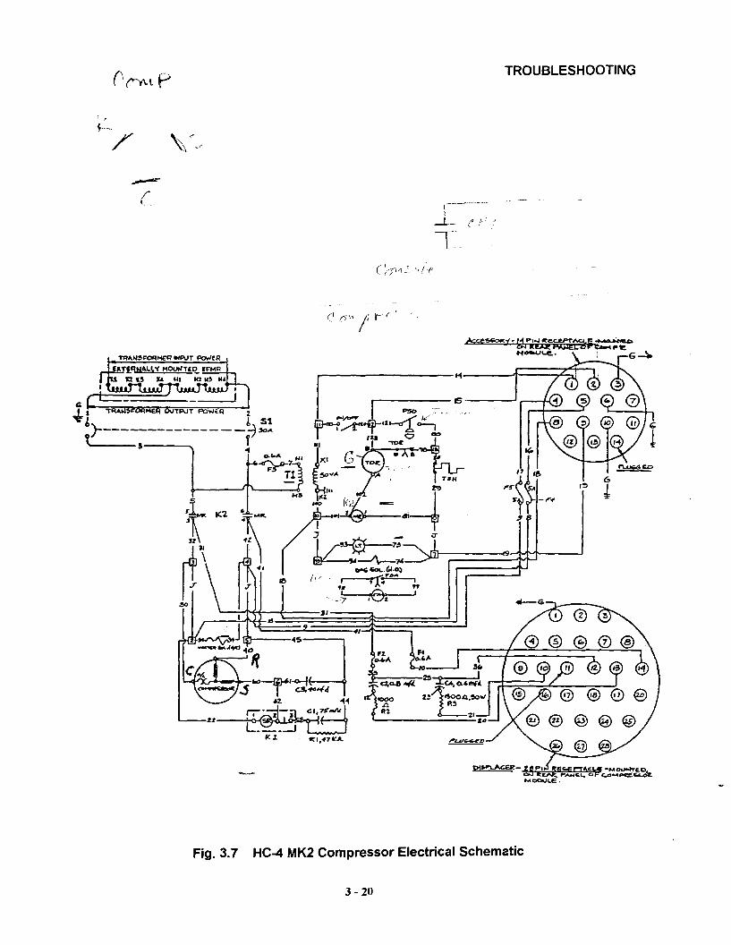
Fig. 3.7 HC-4 MK2 Compressor Electrical Schematic
3 - 20
TROUBLESHOOTING
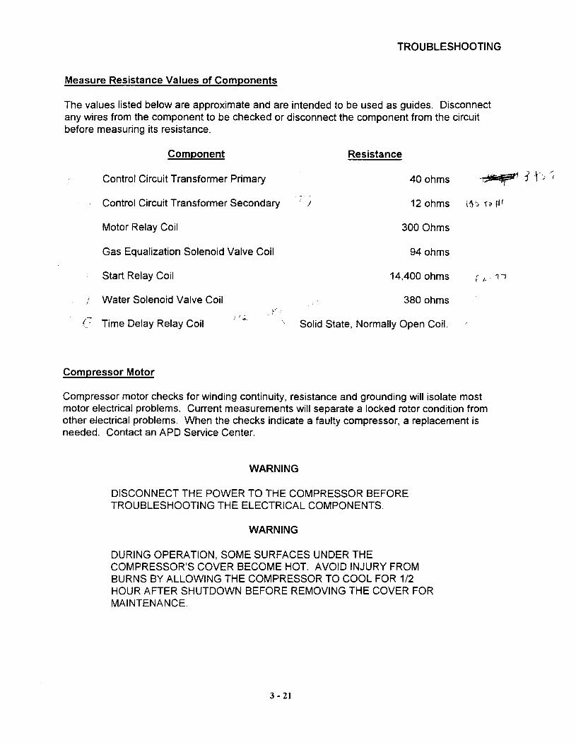
Measure Resistance Values of Components
The values listed below are approximate and are intended to be used as guides. Disconnectany wires from the component to be checked or disconnect the component from the circuitbefore measuring its resistance.
Component
Control Circuit Transformer Primary
Resistance
40 ohms
Control Circuit Transformer Secondary
Motor Relay Coil
Gas Equalization Solenoid Valve Coil
! 12 ohms l(\?:l n 1/'
300 Ohms
94 ohms
Start Relay Coil
/ Water Solenoid Valve Coil
(~ Time Delay Relay Coil
Compressor Motor
14,400 ohms
380 ohms
Solid State, Normally Open Coil.
Compressor motor checks for winding continuity, resistance and grounding will isolate mostmotor electrical problems. Current measurements will separate a locked rotor condition fromother electrical problems. When the checks indicate a faulty compressor, a replacement isneeded. Contact an APD Service Center.
WARNING
DISCONNECT THE POWER TO THE COMPRESSOR BEFORETROUBLESHOOTING THE ELECTRICAL COMPONENTS.
WARNING
DURING OPERATION, SOME SURFACES UNDER THECOMPRESSOR'S COVER BECOME HOT. AVOID INJURY FROMBURNS BY ALLOWING THE COMPRESSOR TO COOL FOR 1/2HOUR AFTER SHUTDOWN BEFORE REMOVING THE COVER FORMAINTENANCE.
3 - 21
TROUBLESHOOTING
WARNING
PERMIT ONLY QUALIFIED ELECTRICAL TECHNICIANS TO OPENELECTRICAL ENCLOSURES, TO PERFORM ELECTRICAL CHECKSFOR TO PERFORM TESTS WITH THE POWER SUPPLYCONNECTED AND WIRING EXPOSED. FAILURE TO OBSERVETHIS WARNING CAN RESULT IN INJURY OR DEATH FROMELECTRIC SHOCK.
Winding Continuity, Grounding and Resistance
1. Disconnect the power to the compressor.
2. Remove the compressor's cover.
3. Remove the terminal box cover from the top of the compressor motor to expose the threeterminals R, S, and C. See Fig. 3.8. Disconnect wires 40, 60, and 30 from terminals R, S,and C respectively.
I4. With an ohmmeter, check the resistance across compressor terminals C and R.
Resistance should be 0.8 to 1.2 ohms. If the resistance is outside this range, consultan APD Service Center. If there is no continuity, the winding is open. Consult an APDService Center.
'd.' I5. With an ohmmeter, check the tesistance across compressor terminals C and S.
Resistance should be 1.8 to '2.2 ohms. If the resistance is outside this range, consultan APD Service Center. If there is no continuity, the winding is open. Consult an APDService Center.
6. With an ohmmeter, check for continuity between compressor terminal C and one ofthe copper tubes entering the compressor housing. If there is continuity, the motor isgrounded. Consult an APD Service Center. ex.
7. If the motor passes these electrical checks, reconnect wires 40,60, and 30 to compressorterminals R, S, and C respectively.
8. Replace the terminal box cover and the cover of the compressor module, unless currentmeasurement is to be performed.
3 - 22

TROUBLESHOOTING
...,
Compressor Motor Terminals
TemperatureOverload Switch
Fig. 3.8 Compressor Terminals
Current Measurement
1. Disconnect the power to the compressor.
ctrical chassis box.Remove the compressor's top cover and the cover from t2.
3. Clamp the ammeter onto one of the power wires on the ,.breaker. The current can range up to 70 amperes. Use a·clamp-on ammeter.
4. Reconnect the power to the compressor.
5. Start the compressor.
6. Read the ammeter, then stop the compressor.
• A reading of 0 amps indicates an open circuit.
• A reading of 14 to 20 amps is normal at steady-state operating conditions.
3 - 23

TROUBLESHOOTING
• A reading of 20 to 40 amps indicates a defective relay, start-run capacitor, orbad motor windings. Check the resistance of each to detect the faultycomponent.
• A reading of 68 amps indicates a locked rotor. Consult an APD Service Center.
• A reading of full scale, along with a tripped circuit breaker or a blown controlcircuit fuse, indicates a short circuit in the chassis wiring or motor.
7. Remove the ammeter.
8. Replace the electrical chassis box cover and the compressor's cover.
'i~".~.: .
'::, ",',-.,
');
3 - 24
PARTS
Ordering
The nameplate fastened to the rear panel of the compressor housing identifies the compressoras follows:
Model NumberPart NumberSerial Number.
Furnish this complete information when ordering parts. Also, order parts by part number andname. Refer to the next section for Parts Identification and Numbers.
3 - 25

PARTS
Fig.3.9 Parts Identification
3 - 26

PARTS
Parts Identification and Numbers (See Fig. 3.9)
Item Part Name Part Number
1 Compressor Assembly 256035E
2 O-Ring (2), Size 4 Aeroquip Coupling 77183
3 Caster (4) 49133
4 Pressure Relief Valve 53028
5 Adsorber Assembly F256390A
6 Internal By-Pass Valve 270067A
7 Oil Capillary Filter 50315
8 Gas Equalization Solenoid Valve 254990C
9 Pressure Gauge, Panel Mount, 2-lnch Dial 50532
10 Oil Separator Assembly 2547320
11 Power Switch 38850
12 Elapsed Time Meter 35008
3 - 27

®
PARTS
Fig. 3.10 Parts Identification
3 - 28

PARTS
Parts Identification and Numbers (See Figs. 3.9 and 3.10)
Item Part Name Part Number
13 Oil Differential Pressure Switch Assembly 256089C
14 Oil Injection Filter Assembly 2550088
15 Oil Injection Orifice 2560668
16 Oil Capillary Assembly 254763C
17 Gasket Seal (2), Aeroquip Coupling 77002
18 O-Ring (2), Aeroquip Coupling 47102
19 Nylon Washer (2), Aeroquip Coupling 72628
20 Lock Washer (2), Aeroquip Coupling 46401
21 Lock Nut (2), Aeroquip Coupling 46101
22 Dust Cap (2), Aeroquip coupling 45301
23 Power Cable 2565078
24 Circuit 8reaker S1, 30AJ 250 VAC/2 Pole 34668
25 Fuse F1, F2, F3, 0.6 amp 34653
26 Fitting (2), Water 14505
27 Gasket Seal, Size 4 Aeroquip Coupling 77003
28 Temperature Overload Switch in Retainer 256034A2
29 Receptacle Cap (2) 34489
3 - 29
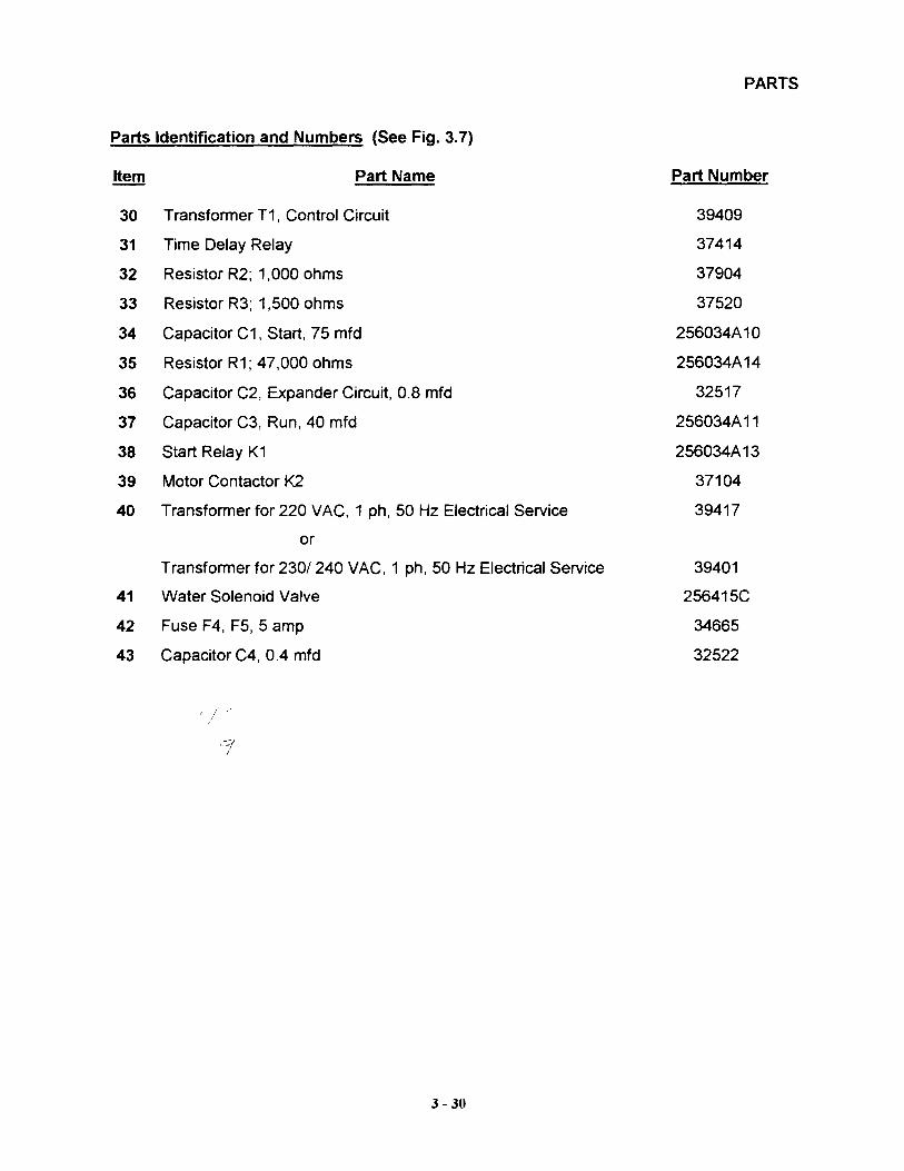
Parts Identification and Numbers (See Fig. 3.7)
PARTS
Item Part Name Part Number
30 Transformer T1, Control Circuit 39409
31 Time Delay Relay 37414
32 Resistor R2; 1,000 ohms 37904
33 Resistor R3; 1,500 ohms 37520
34 Capacitor C1, Start, 75 mfd 256034A10
35 Resistor R1; 47,000 ohms 256034A14
36 Capacitor C2, Expander Circuit, 0.8 mfd 32517
37 Capacitor C3, Run, 40 mfd 256034A11
38 Start Relay K1 256034A13
39 Motor Contactor K2 37104
40 Transformer for 220 VAC, 1 ph, 50 Hz Electrical Service 39417
or
Transformer for 230/ 240 VAC, 1 ph, 50 Hz Electrical Service 39401
41 Water Solenoid Valve 256415C
42 Fuse F4, F5, 5 amp 34665
43 Capacitor C4, 0.4 mfd 32522
3 - 30
Revision A: April 1997
OIL CHARGING VESSEL
TECHNICAL MANUAL
APD CRYOGENICS INC1833 Vultee Street
Allentown, PA 18103
263776A

READ THESE INSTRUCTIONS BEFORE USING THE OIL CHARGING VESSEL
NOTE
File this manual in the Accessory section of your technical manual.
1.0 SCOPE
The following instructions define the proper use of the oil charging vesselsPIN 263775A1, - A2 and - A3 for helium compressors.
WARNINGS
THE OIL CHARGING VESSEL IS PRESSURIZED WITH 210 kPa (30 psig) HELIUM GASAS RECEIVED. AFTER USE IT WILL CONTAIN SYSTEM PRESSURES OF - 2070 kPa(300 psig). UNCONTROLLED PRESSURE RELEASE CAN CAUSE INJURY TOPERSONNEL IN THE WORK AREA.
WHEN HANDLING PRESSURIZED COMPONENTS, ALWAYS WEAR EYE PROTECTION.
USE TWO WRENCHES WHEN DISCONNECTING THE OIL CHARGING VESSEL FROMTHE COMPRESSOR TO AVOID LOOSENING THE COMPRESSOR OIL FILL COUPLING.
NEVER APPLY HEAT TO A PRESSURIZED COMPONENT.
WHEN VENTING THE USED OIL CHARGING VESSEL, AIM THE EXHAUST FROM THEVENTING ADAPTER AWAY FROM PERSONNEL TO PREVENT INJURY DUE TO THERELEASE OF HELIUM GAS AND REMNANT OIL.
CAUTIONS
BE SURE THE GASKET SEAL IS IN PLACE AND CLEAN ON THE MALE AEROQUIP OILFILL COUPLING ON THE TOP OF THE COMPRESSOR MOTOR.
DO NOT ALLOW AIR TO GET INTO THE COMPRESSOR. KEEP THE COUPLINGSALIGNED WHEN CONNECTING THE OIL CHARGING VESSEL TO THE COMPRESSOR OILFILL COUPLING.
VENT THE USED OIL CHARGING VESSEL PER THE PROCEDURE FOR SAFE DISPOSALIN SECTION 3.0.
MODIFICATION TO EQUIPMENT WITHOUT THE CONSENT OF THE MANUFACTURERWILL VOID THE WARRANTY.
2.0 PROCEDURE FOR ADDING OIL TO A COMPRESSOR
2.1 Turn off the compressor.
2.2 Disconnect the electrical power to the compressor.
2.3 Remove the top cover from the compressor.
1

READ THESE INSTRUCTIONS BEFORE USING THE OIL CHARGING VESSEL
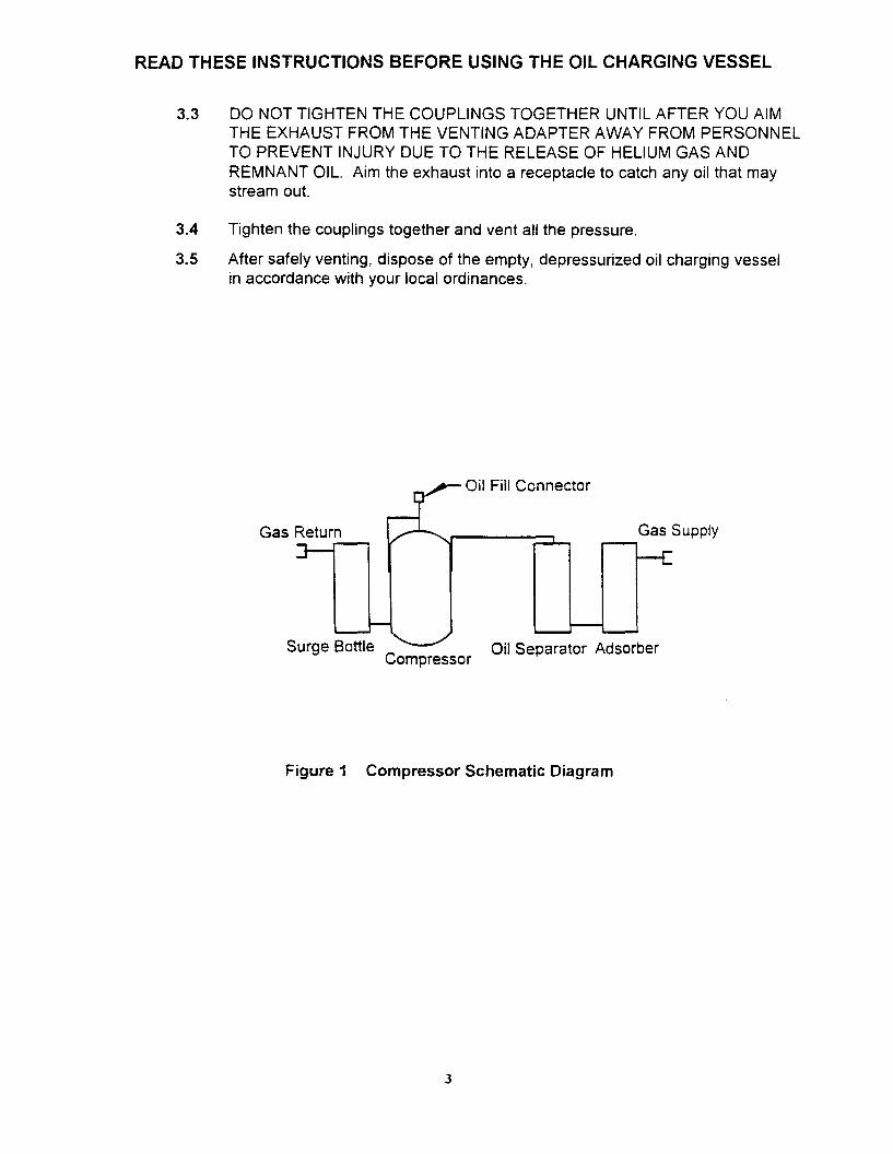
2.4 Locate the size 4, male Aeroquip coupling on top of the compressor motor.This is the oil fill connection. Refer to the schematic diagram, Figure 1,in this manual.
2.5 Remove the dust cap from the compressor oil fill coupling and retain the cap.
2.6 Unpack a new oil charging vessel. Verify that you have the correct vessel forthe compressor to be charged. Read these instructions. Set aside the separatemale Aeroquip venting adapter.
PART NUMBER OIL QUANTITY COMPRESSOR
263775A1 100 mL HC - 20 Series
263775A2 150 mL HC-4 Series
263775A3 200 mL HC-8 Series
2.7 Remove the dust cap from the oil charging vessel female Aeroquip coupling.
2.8 Check that the mating surfaces of both couplings are clean and that the gasketseal is in place on the male Aeroquip oil fill coupling.
2.9 Align and thread the oil charging vessel coupling onto the oil fill coupling.
2.10 Use two 3/4" (19 mm) wrenches: one to hold the compressor oil fill couplingstationary, and one to tighten the oil charging vessel coupling onto it. Tightento 1.4 - 1.6 kgf m (1 0 - 12 Ib ft).
2.11 Allow the oil in the charging vessel to drain into the compressor for 3 hours.
2.12 After 3 hours, remove the oil charging vessel. Use two wrenches to avoidloosening the compressor oil fill coupling.
2.13 Re-install the dust cap on the compressor oil fill coupling.
2.14 Re-install the compressor top cover.
2.15 Re-connect the electrical power to the compressor. The compressor can now bereturned to normal operation.
3.0 PROCEDURE FOR VENTING A USED OIL CHARGING VESSEL
3.1 The oil charging vessel is supplied with a separate venting adapter, consisting ofa male Aeroquip coupling attached to a fitting that contains a small orifice. Theorifice prevents the pressurized helium and remnant oil from venting too rapidly.
3.2 After using the oil charging vessel to add oil to a compressor, align the ventingadapter male Aeroquip coupling with the oil charging vessel female Aeroquipcoupling.
2
READ THESE INSTRUCTIONS BEFORE USING THE OIL CHARGING VESSEL
3.3 DO NOT TIGHTEN THE COUPLINGS TOGETHER UNTIL AFTER YOU AIMTHE EXHAUST FROM THE VENTING ADAPTER AWAY FROM PERSONNELTO PREVENT INJURY DUE TO THE RELEASE OF HELIUM GAS ANDREMNANT OIL. Aim the exhaust into a receptacle to catch any oil that maystream out.
3.4 Tighten the couplings together and vent all the pressure.
3.5 After safely venting, dispose of the empty, depressurized oil charging vesselin accordance with your local ordinances.
Oil Fill Connector
Gas Return Gas Supply
Surge Bottle Oil Separator AdsorberCompressor
Figure 1 Compressor Schematic Diagram
3
Revision C: December 1994
CHAPTER 5
GAS LINES
APD CRYOGENICS INC1833 Vultee Street
Allentown, PA 18103
261320A

CHAPTER 5 - GAS LINES
DESCRIPTION . .
SPECIFICATIONSMinimum Bend RadiusPressure and Temperature Ratings.Identification LabelsInstallation Tools.
MAINTENANCE . . . . . . .Disconnecting Gas Lines
From the Compressor.From the Expander.
Leak Checking .Gas Line Repair . .Venting . . . . . .Repair Self-Sealing Couplings
Replace the Gasket Seal ..Repair or Replace the Coupling
Gas Cleanup and Recharging. . . .Gas Cleanup and Recharging (Systems Using Nycoi1 Gas Lines)
PARTSOrdering.. . .Parts Identification and Numbers.
ILLUSTRATIONS LIST
Page
5.1
5.25.25.25.25.2
5.35.35.35.45.45.55.55.65.65.75.85.9
5.115.115.11
Fig. 5.1Fig. 5.2Fig. 5.3Fig. 5.4Fig. 5.5Fig. 5.6Fig. 5.7Fig. 5.8
RLE/dmkPL410EN2/48
Typical Gas Line Construction . . . . .Disconnect Gas Line from Compressor . .Break Gas Line Connection from ExpanderDisconnect Gas Line from Expander . . .Aeroquip Male Coupling Parts .Remove Coupling from Gas LineAeroquip Female Coupling PartsParts Identification . .
- v.i -
5.15.35.45.45.65.75.75.11

DESCRIPTION
Gas lines are needed to connect compressors to expanders to complete thesystem. Gas lines are constructed from convoluted stainless steel tubingcovered with metal braid or from soft copper tubing or Nycoil tubing.All gas lines are equipped with Aeroquip self-sealing couplings and arefurnished cleaned, charged with helium gas and leak checked.
Nycoil gas lines are permeable. Gas can diffuse through the nylon tubingwall. System equalization pressure may decrease in as little time as two (2)months. Also, air may diffuse into the gas line and contaminate the systemhelium gas with other gases and water vapor.
System performance and adsorber life will be less than that of a system usingstainless steel or copper gas lines.
See special procedures for Gas Cleanup and Recharging in the Maintenancesection.
Each cryogenic system includes interconnecting gas lines to carry helium gasrefrigerant to and from the components. A gas line carries high pressure gasfrom the compressor to the expander and another gas line returns lowerpressure gas to the compressor.
Flexible gas lines simplify installation. The self-sealing couplings maintainthe gas charge and purity by minimizing gas loss when connections are beingmade or broken and by preventing the entrance of contaminants. Dust plugsprotect the coupling threads from damage and also help to maintain cleanliness.
lCOUPLINGNUT
l"ETAL BRAID
CONVOLUTEDMETAL TUBING
ADAPTER
FEMALE COUPLINGOUSTPLUG
~
II
Fig. 5.1 Flexible Gas Line Construction
- 5.1 -

SPECIFICATIONS
Minimum Bend Radius
Gas Line Type
Convoluted Stainless Steel
Copper Tubing, using atube bender
Copper Tubing, without'a tube bender
Diametermm (inches)
13 (1/2) I.D.
17 (5/8) O.D.
17 (5/8) O.D.
NOTE
Minimum Bend Radiusmm (inches)
230 (9)
57 (2 1/4)
457 (18)
Working length of a Nycoi1 gas line is two (2)times its coiled length.
Pressure andTemperature Ratings
Design pressure, max.Operating pressure, max.Charge pressure, max.Operating temperature, max.Operating temperature, min.
Identification Labels
Stainless Steeland Copper
2760 kPa (400 psig)2410 kPa (350 psig)1860 kPa (270 psig)49°C (120°F)
4°C, (40°F)
Nycoil
2760 kPa (400 psig)1930 kPa (280 psig)1380 kPa (200 psig)
49°C (120°F)4°C (40°F)
Labels on the gas lines identify their function in the system as follows:
SUPPLY (color coded red)
RETURN (color coded green)
helium gas supply to the expanderfrom the compressor.
helium gas return from the expanderto the compressor.
Separate labels are furnished with standard gas lines for the customer toattach the labels. See the Installation section in the System chapter.
Installation Tools
Properly sized open end wrenches are needed to install and remove gas lines.
For installation, gas lines with size 8 Aeroquip couplings require one each ofthese open end wrenches, contained in wrench kit PIN 255438A:
1" PIN 43800; 1 1/8" PIN 43413; 1 3/16" PIN 43802
For MRI systems with an RF shield, gas feedthroughs may be furnished forinstallation through the shield. Wrench kit PIN 260454A contains the abovethree wrenches plus a 1 7/8" open end wrench, PIN 43447, to fit the nut on themagnet side of the gas feedthroughs.
- 5.2 -

MAINTENANCE
Disconnecting Gas Lines
WARNING
EXTREME COLD CAN CAUSE FROSTBITE. WEN HANDLINGSYSTEM COMPONENTS, BE CAREFUL NOT TO TOUCH ANYFROSTED PARTS.
WARNING
DISCONNECT GAS LINES ONLY WEN THE COMPRESSOR ISSTOPPED. DISCONNECTING THE EXPANDER WILE IT ISCOLD CAN CREATE EXCESSIVELY HIGH INTERNAL PRESSUREAS THE GAS WARMS. MATERIAL FAILURE AND UNCONTROLLEDPRESSURE RELEASE CAN CAUSE INJURY TO PERSONNEL INTHE WORK AREA.
WARNING
USE TWO WRENCHES WEN DISCONNECTING A GAS LINECOUPLING TO AVOID LOOSENING THE MATING COUPLING.GAS PRESSURE CAN PROJECT THE COUPLING WITHENOUGH FORCE TO CAUSE INJURIES.
CAUTION
KEEP THE GAS LINE COUPLINGS ALIGNED WEN MAKINGOR BREAKING A COUPLING CONNECTION. LEAKAGE CANOCCUR DUE TO THE WEIGHT OF THE GAS LINE OR DUETO A SHARP BEND NEAR THE CONNECTION.
From the Compressor
1. Always use two wrenches. Use one wrench to hold the couplingadapter. Use the second wrench to turn the gas line coupling nutfrom the compressor coupling. See Fig. 5.2.
2. Screw a dust cap finger tight on to the compressor coupling.
TURN
'-----y-JJ "GAS LINE COUPLING
COMPRESSOR COUPLING
Fig. 5.2 Disconnect Gas Line from Compressor
- 5.3 -

MAINTENANCE
From the Expander
1. Always use two wrenches. Use one wrench to hold the expandercoupling. Use the second wrench on the gas line coupling nut tobreak the connection. See Fig. 5.3.
2. After breaking the connection, hold the coupling adapter with onewrench.
Remove the gas line coupling from the expander coupling with thesecond wrench. See Fig. 5.4.
3. Screw a dust cap finger tight on to the expander coupling.
Fig. 5.3
TURN
~i
Break Gas LineConnection from Expander
Fig. 5.4
TURN
Disconnect Gas Linefrom Expander
Leak Checking
Leakage of helium gas is the only likely problem to originate on a gas line.Use of a helium mass spectrometer leak detector is recommended. If no massspectrometer is available, a liqUid leak detector solution may be used on thecoupling joints.
With the gas lines connected to the compressor and to the expander, leak checkthe connected coupling joints.
The flat gasket in the face of the male coupling seals the joint. A leak atthis gasket seal can be detected only when a gas line is connected. A leakhere can be caused by:
* the coupling not fully tightened.* a worn, damaged or missing gasket seal.* dirt on or under the gasket seal.* dirt on the female coupling's mating surface.* damaged parts on either coupling which prevent proper mating or
sealing.
- 5.4 -

MAINTENANCE
Gas Line Repair
Leaks in the convoluted metal tubing cannot be repaired. Discard the damagedgas line and install a new one.
Leaks at welded joints require special skills to repair. Consult the APDService Department.
Leaks at the self-sealing couplings can be repaired by replacing worn ordamaged parts. Vent the gas line before beginning to disassemble it, exceptwhen replacing a gasket seal.
When couplings are frequently disconnected and reconnected, it is important towipe the mating parts (threads and faces) with a clean, lint-free tissue orcloth.
Venting
1. Disconnect the gas line from the system. Install a dust cap on eachof the male couplings of the compressor and expander, or on the RFgas feedthroughs, if used in the system.
NOTE
Adapter fittings are available as optional accessoriesfrom APD.
2. Be sure the valve on adapter fitting PIN SK82l7A2 is closed. Ifonly one coupling on the gas line assembly is to be repaired,install the adapter fitting on the good coupling. Use two wrenches.
3. Slowly open the valve on the adapter fitting to vent the entirecharge of helium gas.
4. Close the valve on the adapter fitting. Do not remove the adapterfitting. It will be used for gas cleanup and recharging.
NOTE
Gas cleanup and recharging of the gas line arealways required if a coupling has been repaired.Instead of venting the gas line to atmosphericpressure, some operators prefer to connect anadapter fitting and a charge line to the couplingnot being repaired, to purge the gas line withhelium during repair. Set the helium gasregulator at 5 psig or less to prevent air fromentering the gas line and contaminating it.
- 5.5 -

MAINTENANCE
Repair Self-Sealing Couplings
WARNING
ALWAYS VENT A GAS CHARGED COMPONENT BEFORE BEGINNINGTO DISASSEMBLE ITS COUPLINGS. GAS PRESSURE CANLAUNCH A LOOSE COUPLING WITH ENOUGH FORCE TO CAUSEPERSONAL INJURY.
CAUTION
MODIFICATION TO EQUIPMENT WITHOUT THE CONSENT OFTHE MANUFACTURER WILL VOID THE WARRANTY.
Damaged threads, leaking seals or a leaking valve assembly may requirereplacement of coupling parts or replacement of the complete coupling half.
Replace the Gasket Seal
From repeated connecting and disconnecting the coupling, the gasket seal justinside the face of a male coupling may begin to leak and require replacement.
The gasket seal is replaced while the gas line is disconnected. See Fig. 5.5.
1. Carefully pry the old gasket seal from its recessed ring in the body.
2. Lightly coat the new gasket seal with vacuum grease and press itinto the ring.
GASKET SEAL
rVALVE ASSEMBLY rBODY
eM Q--I4ftnrr~
O-RINGADAPTER
Fig. 5.5 Aeroquip Male Coupling Parts
- 5.6 -
MAINTENANCE
Repair or Replace the Coupling
This procedure applies to both male and female couplings on gas lines,compressor and expander.
1. Vent the charged component using the venting procedure in theMaintenance section of the appropriate chapter.
2. If the coupling to be repaired has the venting adapter fittingattached, remove the adapter fitting.
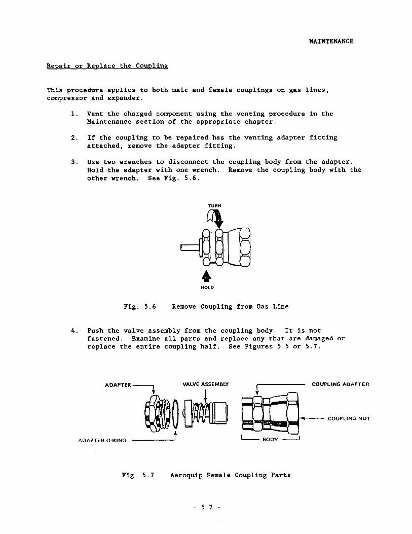
3. Use two wrenches to disconnect theHold the adapter with one wrench.other wrench. See Fig. 5.6.
coupling body from the adapter.Remove the coupling body with the
TURN
HOLD
Fig. 5.6 Remove Coupling from Gas Line
4. Push the valve assembly from the coupling body. It is notfastened. Examine all parts and replace any that are damaged orreplace the entire coupling half. See Figures 5.5 or 5.7.
ADAPTER O·RING
COUPLING ADAPTER
COUPLING NUT
- ,....-,- -'011(
"-- ...- -",-
L- BODY-.J
ADAPTER --""'t VALVE ASSEMBLY
I~~t
Fig. 5.7 Aeroquip Female Coupling Parts
- 5.7 -
MAINTENANCE
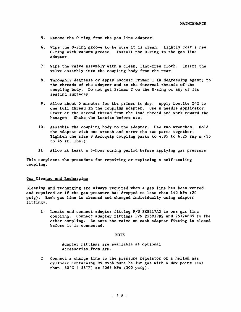
5. Remove the O-ring from the gas line adapter.
6. Wipe the O-ring groove to be sure it is clean. Lightly coat a newO-ring with vacuum grease. Install the O-ring in the gas lineadapter.
7. Wipe the valve assembly with a clean, lint-free cloth. Insert thevalve assembly into the coupling body from the rear.
8. Through1y degrease or apply Locquic Primer T (a degreasing agent) tothe threads of the adapter and to the internal threads of thecoupling body. Do not get Primer T on the O-ring or any of itsseating surfaces.
9. Allow about 5 minutes for the primer to dry. Apply Loctite 242 toone full thread in the coupling adapter. Use a needle applicator.Start at the second thread from the lead thread and work toward thehexagon. Shake the Loctite before use.
10. Assemble the coupling body to the adapter. Use two wrenches. Holdthe adapter with one wrench and screw the two parts together.Tighten the size 8 Aeroquip coupling parts to 4.85 to 6.25 kgf m (35to 45 ft. 1bs.).
11. Allow at least a 6-hour curing period before applying gas pressure.
This completes the procedure for repairing or replacing a self-sealingcoupling.
Gas Cleanup and Recharging
Cleaning and recharging are always required when a gas line has been ventedand repaired or if the gas pressure has dropped to less than 140 kPa (20psig). Each gas line is cleaned and charged individually using adapterfittings.
1. Locate and connect adapter fitting PIN SK8217A2 to one gas linecoupling. Connect adapter fittings PIN 255919B2 and 257246C5 to theother coupling. Be sure the valve on each adapter fitting is closedbefore it is connected.
NOTE
Adapter fittings are available as optionalaccessories from APD.
2. Connect a charge line to the pressure regulator of a helium gascylinder containing 99.995% pure helium gas with a dew point lessthan -50°C (-58°F) at 2065 kPa (300 psig).
- 5.8 -
MAINTENANCE
WARNING
NEVER USE COMPRESSED GAS FROM A CYLINDER WITHOUTA PROPER REGULATOR. OVERPRESSURIZING CAN CAUSEPERSONAL INJURY IF THE SYSTEM EQUIPMENT RUPTURES.
3. Open the gas cylinder valve. While connecting the charge line tothe valve on one of the adapter fittings, thoroughly purge thecharge line from the regulator. It is important to remove all aircontaminants to prevent them from entering the gas line.
4. Adjust the gas cylinder regulator to 690 kPa (100 psig). Open thevalve on the adapter fitting and charge the gas line to 690 kPa (100psig).
5. Close the valve on the helium gas cylinder (not on the regulator).
6. Open the vent valve. Watch the regulator pressure gauge. When thepressure falls to 35 to 70 kPa (5 to 10 psig) , close the ventvalve. Open the gas cylinder valve to increase the pressure to 690kPa (100 psig). Close the gas cylinder valve.
7. Repeat step 6 five times.
8. Close the valve on the adapter fitting used for charging. Open thegas cylinder valve. Adjust the pressure regulator to theequalization pressure of the system. Refer to the Specificationsection in the System chapter.
9. Open the valve on the adapter fitting and charge the gas line to theequalization pressure.
10. Close the valve on the adapter fitting. Close the gas cylindervalve. Disconnect the charge line from the adapter fitting. Storethe charge line to keep it clean.
11. Remove the adapter fittings.
This completes the procedure for gas cleanup of a gas line.
Gas Cleanup and Recharging (Systems Using Nycoil Gas Lines)
Because Nycoil gas lines are permeable, frequent, scheduled maintenance isrequired on the system every 60 or 90 days, depending on the system components.
For system using compressor models HC-4 (series), lR04WSL or lR04WOI, performGas Cleanup and Recharging every 90 days even if the system has notoperated.
For systems using compressor models HC-2 (series), lR02W, lR02A, lR02WOI,lL02W or lL02A, perform Gas Cleanup and Recharging every 60 days even ifthe system has not operated.
- 5.9 -
MAINTENANCE
This schedule is based on a system equalization pressure loss of 70 kPa (10psig). If the equalization pressure drops 70 kPa (10 psig) or more during the60- or 90-day period, perform Gas Cleanup and Recharging procedure as soon asthe pressure loss is detected. Do not wait for the expiration of the 60 or 90days.
1. Using two wrenches, disconnect the gas lines from the compressorand from the expander.
2. For gas cleanup of Nycoil gas lines, follow the same procedure forGas Cleanup and Recharging (Stainless Steel and Copper Gas Lines)in this section.
3. For gas cleanup of the compressor and expander, see the Gas Cleanupprocedures in the compressor and Expander sections.
4. Using two wrenches, reconnect the components. Check theequalization pressure of the system after completing thereinstallation.
This completes the procedure for gas cleanup of components used in a systemcontaining Nycoil gas lines.
- 5.10 -
Ordering
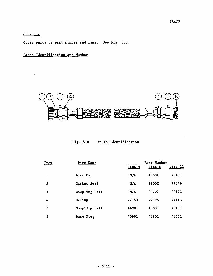
Order parts by part number and name. See Fig. 5.8.
Parts Identification and Number
PARTS
Fig. 5.8 Parts Identification
Item Part Name Part NumberSize 4 Size 8 Size 12
1 Dust Cap N/A 45301 45401
2 Gasket Seal N/A 77002 77046
3 Coupling Half N/A 44701 44801
4 O-Ring 77183 77196 77113
5 Coupling Half 44901 45001 45101
6 Dust Plug 45501 45601 45701
- 5.11 -
Addendum To Helium Compressor Technical ManualsFor a Compressor With a Gas Fill Port
APD CRYOGENICS INC.1833 Vultee Street
Allentown, PA 18103
Revision A: May 1996 262780A

ADDENDUM 262780A
NOTE
Place this Addendum in the Compressor section of your technicalmanual, ahead of the Compressor technical manual.
This Addendum applies to the following compressors which have a gas fill and vent porton the compressors front panel:
Compressor Model Number
HC - 20 - FF
HC - 4MK2 - FF
HC - 8C1 - FF
HC - 8C5 - FF
Compressor Part Number
256639E 18G - FF256639E 15G - FF256639E 16G - FF
260341E 18G - FF260341E 15G - FF260341 E 16G - FF
258492E 20J - FF
261200E 20J - FF
1.0 Scope
This addendum to the compressor technical manual describes the charging and ventingprocedures for a compressor with the gas fill port.
2.0 Tools and Materials Required
WARNING
NEVER USE COMPRESSED HELIUM GAS FROM A CYLINDER WITHOUT APROPER REGULATOR. OVER PRESSURIZATION CAN CAUSE PERSONALINJURY IF THE SYSTEM EQUIPMENT RUPTURES
WARNING
WHEN HANDLING PRESSURIZED GAS LINES AND OTHER PRESSURIZEDEQUIPMENT, ALWAYS WEAR EYE PROTECTION
• Gas Supply -- A regulated helium gas cylinder containing 99.995% pure heliumwith a dew point less than -50 0 C (-58 0 F) at 2070 kPa (300 psig).
• 1/4" 0.0. tube charge line from helium supply to compressor.
• Swagelok~ nut and ferrules (PIN's 8-402-1, 8-403-1 and 8-404-1; reference APDPIN's 12301,12302 and 12303, respectively).
• Two 9/16" open-end wrenches.
1
ADDENDUM 262780A
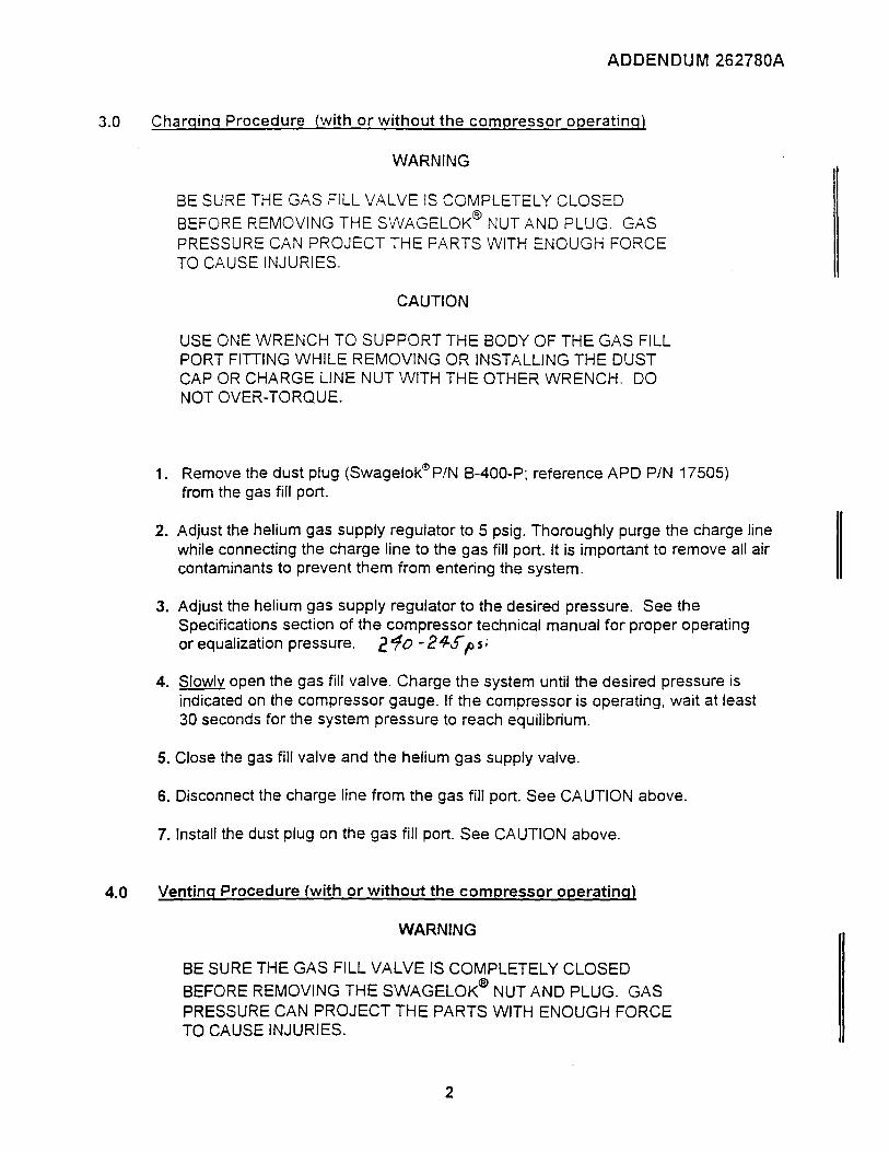
3.0 Charging Procedure {with or without the compressor ooeratinal
WARNING
BE SURE THE GAS FILL VALVE IS COMPLETELY CLOSED
BEFORE REMOVING THE SWAGELOK® NUT AND PLUG. GASPRESSURE CAN PROJECT THE PARTS WITH ENOUGH FORCETO CAUSE INJURIES.
CAUTION
USE ONE WRENCH TO SUPPORT THE BODY OF THE GAS FILLPORT FITTING WHILE REMOVING OR INSTALLING THE DUSTCAP OR CHARGE LINE NUT WITH THE OTHER WRENCH. DONOT OVER-TORQUE.
1. Remove the dust plug (Swagelok~PIN B-400-P; reference APD PIN 17505)from the gas fill port.
2. Adjust the helium gas supply regulator to 5 psig. Thoroughly purge the charge linewhile connecting the charge line to the gas fill port. It is important to remove all aircontaminants to prevent them from entering the system.
3. Adjust the helium gas supply regulator to the desired pressure. See theSpecifications section of the compressor technical manual for proper operatingor equalization pressure. 211fo -24-Sp Si
4. Slowly open the gas fill valve. Charge the system until the desired pressure isindicated on the compressor gauge. If the compressor is operating, wait at least30 seconds for the system pressure to reach equilibrium.
5. Close the gas fill valve and the helium gas supply valve.
6. Disconnect the charge line from the gas fill port. See CAUTION above.
7. Install the dust plug on the gas fill port. See CAUTION above.
4.0 Venting Procedure (with or without the compressor operating)
WARNING
BE SURE THE GAS FILL VALVE IS COMPLETELY CLOSED
BEFORE REMOVING THE SWAGELOK® NUT AND PLUG. GASPRESSURE CAN PROJECT THE PARTS WITH ENOUGH FORCETO CAUSE INJURIES.
2

ADDENDUM 262780A
CAUTION
USE ONE WRENCH TO SUPPORT THE BODY OF THE GAS FILLPORT FiniNG WHILE REMOVING OR INSTALLING THE DUSTCAP WITH THE OTHER WRENCH. DO NOT OVER-TORQUE.
1. Remove the dust plug (Swagelok,!l PIN B-400-P; reference APD PIN 17505) fromthe gas fill port.
2. Slowly open the gas fill valve, less than 2 turns. Vent the system until the desiredpressure is indicated on the compressor gauge. See the Specifications sectionof the compressor technical manual for proper operating or equalization pressure.If the compressor is operating, wait at least 30 seconds for the system pressureto reach equilibrium.
3. Close the gas fill valve.
4. Install the dust plug on the gas fill port. See CAUTION above.
Compressor Front Panel
HELIUMCHARGENENT
SEE ""ISTRUCTIONS INMANUAL ADDENDUM
3
Top Related