


Languages
Pages
Legal

21
H30 SERIES
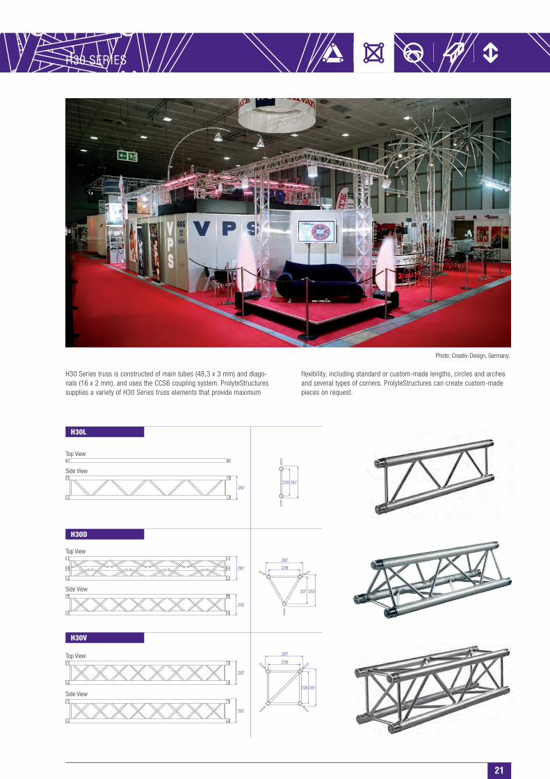
flexibility, including standard or custom-made lengths, circles and arches and several types of corners. ProlyteStructures can create custom-made pieces on request.
H30 Series truss is constructed of main tubes (48,3 x 3 mm) and diago-nals (16 x 2 mm), and uses the CCS6 coupling system. ProlyteStructures supplies a variety of H30 Series truss elements that provide maximum
Top View
Top View
Top View
Side View
Side View
Side View
H30V
H30D
H30L
287
255
287
239
255207
287287239
287
287
287
287239
239
Photo: Creativ-Design, Germany.
22
H30 Series - Standard available Lengths and Codes
Metres Feet Code*
0.25/1.00 m in 5 mm steps 0.82’/3.28’, in 0.2’ steps
0,25 0.82 H30•-L025
0,29 0.95 H30•-L029
0,50 1.64 H30•-L050
0,71 2.33 H30•-L071
0,75 2.46 H30•-L075
1,00 3.28 H30•-L100
1,50 4.57 H30•-L150
2,00 6.56 H30•-L200
2,50 8.20 H30•-L250
3,00 9.84 H30•-L300
3,50 11.48 H30•-L350
4,00 13.12 H30•-L400
4,50 14.76 H30•-L450
5,00 16.40 H30•-L500
*on • indicate L for Ladder, D for Triangular or
V for Square truss. Example: H30V-L200
Technical Specifications - H30 Series
Types Ladder (L), Triangular (D), Square (V)
Alloy EN AW 6082 T6
Main Tubes (Chords) 48,3 x 3 mm
Braces 16 x 2 mm
Coupling System CCS6
Structural data can be found at www.prolyte.com
• Tüv certification only valid for loading table above.• Loading figures are only valid for static loads.• Loading figures are only valid for single spans with supports at both ends.• All static systems, other than single spans, need an individual structural calculation. Please contact a structural engineer or
Prolyte Group for assistance.• Loading figures are calculated according to and in full compliance with European standards (Eurocode).• The self-weight of the trusses is already taken into account.• Loading figures are only valid for the cross sectional orientation of the truss as shown by the icon in the loading table.• The interaction between bending moment and shear force at the connection point is already taken into account.• Truss spans can be assembled from different truss lengths.• Read the manual before assembling, using and loading the truss.
The number of recessed rings in the coupler receiver distinguishes the X and H Series.
X Coupler - 1 ring
H Coupler - 2 rings
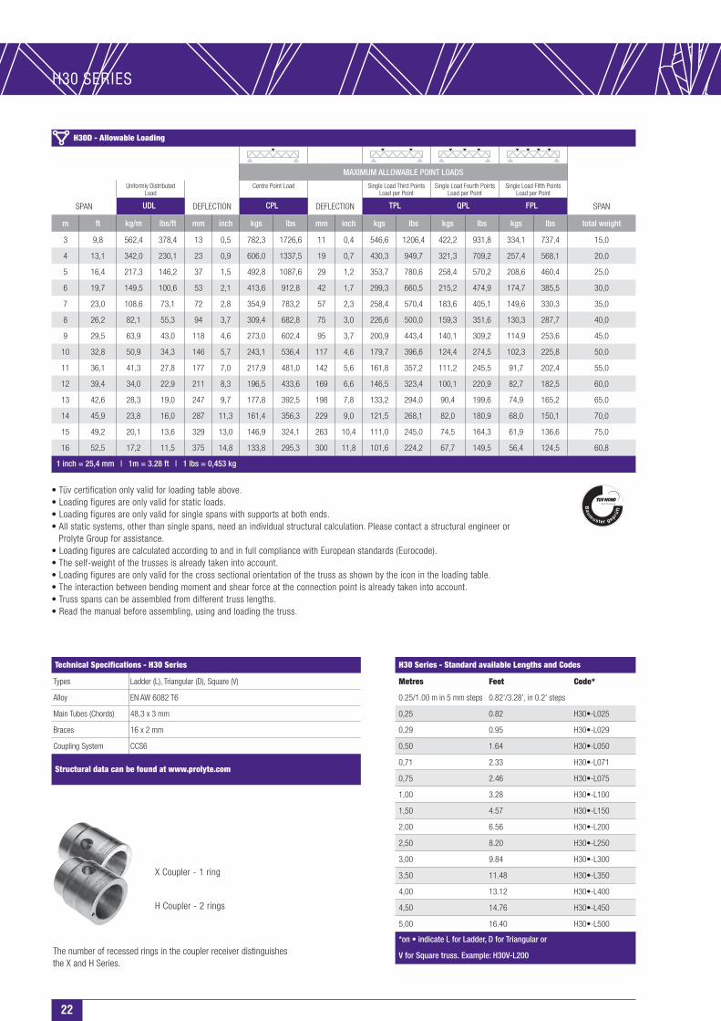
H30D - Allowable Loading
MAXIMUM ALLOWABLE POINT LOADS
Uniformly DistributedLoad
Centre Point Load Single Load Third PointsLoad per Point
Single Load Fourth PointsLoad per Point
Single Load Fifth PointsLoad per Point
SPAN UDL DEFLECTION CPL DEFLECTION TPL QPL FPL SPAN
m ft kg/m lbs/ft mm inch kgs lbs mm inch kgs lbs kgs lbs kgs lbs total weight
3 9,8 562,4 378,4 13 0,5 782,3 1726,6 11 0,4 546,6 1206,4 422,2 931,8 334,1 737,4 15,0
4 13,1 342,0 230,1 23 0,9 606,0 1337,5 19 0,7 430,3 949,7 321,3 709,2 257,4 568,1 20,0
5 16,4 217,3 146,2 37 1,5 492,8 1087,6 29 1,2 353,7 780,6 258,4 570,2 208,6 460,4 25,0
6 19,7 149,5 100,6 53 2,1 413,6 912,8 42 1,7 299,3 660,5 215,2 474,9 174,7 385,5 30,0
7 23,0 108,6 73,1 72 2,8 354,9 783,2 57 2,3 258,4 570,4 183,6 405,1 149,6 330,3 35,0
8 26,2 82,1 55,3 94 3,7 309,4 682,8 75 3,0 226,6 500,0 159,3 351,6 130,3 287,7 40,0
9 29,5 63,9 43,0 118 4,6 273,0 602,4 95 3,7 200,9 443,4 140,1 309,2 114,9 253,6 45,0
10 32,8 50,9 34,3 146 5,7 243,1 536,4 117 4,6 179,7 396,6 124,4 274,5 102,3 225,8 50,0
11 36,1 41,3 27,8 177 7,0 217,9 481,0 142 5,6 161,8 357,2 111,2 245,5 91,7 202,4 55,0
12 39,4 34,0 22,9 211 8,3 196,5 433,6 169 6,6 146,5 323,4 100,1 220,9 82,7 182,5 60,0
13 42,6 28,3 19,0 247 9,7 177,8 392,5 198 7,8 133,2 294,0 90,4 199,6 74,9 165,2 65,0
14 45,9 23,8 16,0 287 11,3 161,4 356,3 229 9,0 121,5 268,1 82,0 180,9 68,0 150,1 70,0
15 49,2 20,1 13,6 329 13,0 146,9 324,1 263 10,4 111,0 245,0 74,5 164,3 61,9 136,6 75,0
16 52,5 17,2 11,5 375 14,8 133,8 295,3 300 11,8 101,6 224,2 67,7 149,5 56,4 124,5 60,8
1 inch = 25,4 mm | 1m = 3.28 ft | 1 lbs = 0,453 kg
H30 SERIES
23
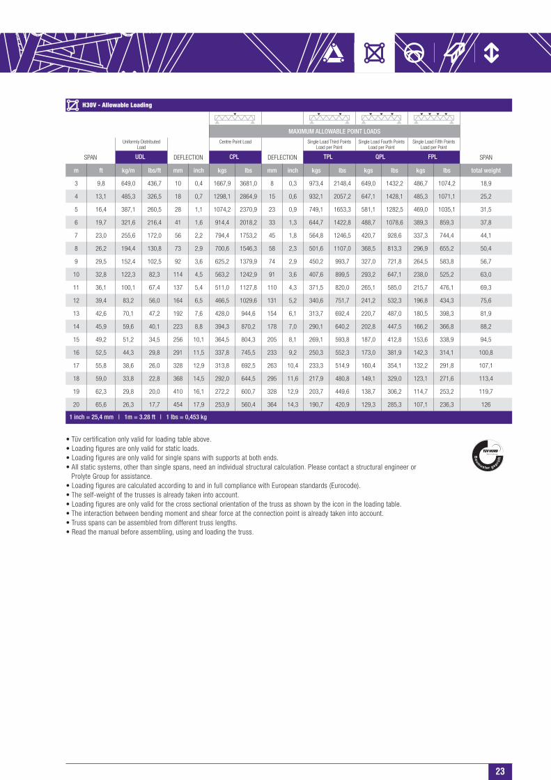
H30V - Allowable Loading
MAXIMUM ALLOWABLE POINT LOADS
Uniformly DistributedLoad
Centre Point Load Single Load Third PointsLoad per Point
Single Load Fourth PointsLoad per Point
Single Load Fifth PointsLoad per Point
SPAN UDL DEFLECTION CPL DEFLECTION TPL QPL FPL SPAN
m ft kg/m lbs/ft mm inch kgs lbs mm inch kgs lbs kgs lbs kgs lbs total weight
3 9,8 649,0 436,7 10 0,4 1667,9 3681,0 8 0,3 973,4 2148,4 649,0 1432,2 486,7 1074,2 18,9
4 13,1 485,3 326,5 18 0,7 1298,1 2864,9 15 0,6 932,1 2057,2 647,1 1428,1 485,3 1071,1 25,2
5 16,4 387,1 260,5 28 1,1 1074,2 2370,9 23 0,9 749,1 1653,3 581,1 1282,5 469,0 1035,1 31,5
6 19,7 321,6 216,4 41 1,6 914,4 2018,2 33 1,3 644,7 1422,8 488,7 1078,6 389,3 859,3 37,8
7 23,0 255,6 172,0 56 2,2 794,4 1753,2 45 1,8 564,8 1246,5 420,7 928,6 337,3 744,4 44,1
8 26,2 194,4 130,8 73 2,9 700,6 1546,3 58 2,3 501,6 1107,0 368,5 813,3 296,9 655,2 50,4
9 29,5 152,4 102,5 92 3,6 625,2 1379,9 74 2,9 450,2 993,7 327,0 721,8 264,5 583,8 56,7
10 32,8 122,3 82,3 114 4,5 563,2 1242,9 91 3,6 407,6 899,5 293,2 647,1 238,0 525,2 63,0
11 36,1 100,1 67,4 137 5,4 511,0 1127,8 110 4,3 371,5 820,0 265,1 585,0 215,7 476,1 69,3
12 39,4 83,2 56,0 164 6,5 466,5 1029,6 131 5,2 340,6 751,7 241,2 532,3 196,8 434,3 75,6
13 42,6 70,1 47,2 192 7,6 428,0 944,6 154 6,1 313,7 692,4 220,7 487,0 180,5 398,3 81,9
14 45,9 59,6 40,1 223 8,8 394,3 870,2 178 7,0 290,1 640,2 202,8 447,5 166,2 366,8 88,2
15 49,2 51,2 34,5 256 10,1 364,5 804,3 205 8,1 269,1 593,8 187,0 412,8 153,6 338,9 94,5
16 52,5 44,3 29,8 291 11,5 337,8 745,5 233 9,2 250,3 552,3 173,0 381,9 142,3 314,1 100,8
17 55,8 38,6 26,0 328 12,9 313,8 692,5 263 10,4 233,3 514,9 160,4 354,1 132,2 291,8 107,1
18 59,0 33,8 22,8 368 14,5 292,0 644,5 295 11,6 217,9 480,8 149,1 329,0 123,1 271,6 113,4
19 62,3 29,8 20,0 410 16,1 272,2 600,7 328 12,9 203,7 449,6 138,7 306,2 114,7 253,2 119,7
20 65,6 26,3 17,7 454 17,9 253,9 560,4 364 14,3 190,7 420,9 129,3 285,3 107,1 236,3 126
1 inch = 25,4 mm | 1m = 3.28 ft | 1 lbs = 0,453 kg
• Tüv certification only valid for loading table above.• Loading figures are only valid for static loads.• Loading figures are only valid for single spans with supports at both ends.• All static systems, other than single spans, need an individual structural calculation. Please contact a structural engineer or
Prolyte Group for assistance.• Loading figures are calculated according to and in full compliance with European standards (Eurocode).• The self-weight of the trusses is already taken into account.• Loading figures are only valid for the cross sectional orientation of the truss as shown by the icon in the loading table.• The interaction between bending moment and shear force at the connection point is already taken into account.• Truss spans can be assembled from different truss lengths.• Read the manual before assembling, using and loading the truss.

24
H30L - Allowable Loading (Span supported on top chord.)
Uniformly DistributedLoad
SPAN UDL DEFLECTION CPL DEFLECTION
m ft kg/m lbs/ft mm inch kgs lbs mm inch
1 3,3 979,2 658,9 1 0,0 979,2 2161,2 1 0,0
2 6,6 389,0 261,7 1 0,0 389,0 858,5 1 0,0
3 9,8 156,0 105,0 2 0,1 234,0 516,4 2 0,1
4 13,1 73,0 49,1 3 0,1 146,0 322,2 3 0,1
5 16,4 36,0 24,2 4 0,2 90,0 198,6 3 0,1
6 19,7 15,0 10,1 3 0,1 45,0 99,3 3 0,1
1 inch = 25,4 mm | 1m = 3.28 ft | 1 lbs = 0,453 kgSpans must be supported at each end.
Loads must be suspended from bottom chord only.
H30L - Allowable Loading (Top chord sideways supported each metre.)
Uniformly DistributedLoad
SPAN UDL DEFLECTION CPL DEFLECTION
m ft kg/m lbs/ft mm inch kgs lbs mm inch
4 13,1 242,8 163,4 18 0,7 619,9 1368,1 15 0,6
5 16,4 193,7 130,3 28 1,1 516,7 1140,5 23 0,9
6 19,7 161,0 108,3 41 1,6 442,2 975,9 33 1,3
7 23,0 124,6 83,9 56 2,2 385,6 851,0 45 1,8
8 26,2 95,4 64,2 73 2,9 341,1 752,9 58 2,3
9 29,5 75,1 50,5 92 3,6 305,2 673,6 74 2,9
10 32,8 60,5 40,7 114 4,5 275,5 608,0 91 3,6
11 36,1 49,6 33,4 137 5,4 250,4 552,7 110 4,3
12 39,4 41,4 27,8 164 6,4 229,0 505,3 131 5,2
1 inch = 25,4 mm | 1m = 3.28 ft | 1 lbs = 0,453 kgSpans must be supported at each end.
Loads must be suspended from bottom chord only.
H30L - Allowable Loading (Top chords sideways supported every 2 metres.)
Uniformly DistributedLoad
SPAN UDL DEFLECTION CPL DEFLECTION
m ft kg/m lbs/ft mm inch kgs lbs mm inch
4 13,1 95,2 64,1 4 0,2 190,5 420,3 4 0,1
5 16,4 60,0 40,4 7 0,3 149,9 330,9 6 0,2
6 19,7 40,8 27,5 10 0,4 122,5 270,3 8 0,3
7 23,0 29,3 19,7 14 0,5 102,5 226,1 11 0,4
8 26,2 21,8 14,7 18 0,7 87,1 192,3 14 0,6
9 29,5 16,6 11,2 23 0,9 74,9 165,3 18 0,7
10 32,8 13,0 8,7 28 1,1 64,8 143,1 22 0,9
11 36,1 10,2 6,9 34 1,3 56,4 124,4 27 1,1
12 39,4 8,2 5,5 40 1,6 49,1 108,3 32 1,3
1 inch = 25,4 mm | 1m = 3.28 ft | 1 lbs = 0,453 kgSpans must be supported at each end.
Loads must be suspended from bottom chord only.
1000
1000
1000
1000
2000
2000
2000
2000
H30 SERIES
Top Related