


Languages
Pages
Legal


INDU
CTIV
EPR
OXI
MIT
YSE
NSO
RSG
XL
GL
-6G
L-8
/8U
GL
-N12
GL-
18H
/18H
LG
X-U
/FU
GX
-NG
XAm
plifie
r-sep
arate
dA
mp
lifie
r B
uilt
-in
GA
-10/
GH
722
GX-U/FUSERIESDC 2-wire Cylindrical Inductive Proximity Sensor Amplifier Built-in
Conforming toEMC Directive
2-wire typeavailable
Oil resistant Metal embeddingpossible
High performance&
ease of use
Robust in tightening
2-color indicator
Compact size: "5.4 mm "0.213 in Long sensing range
GX-5SU(B) is just 5.4 mm 0.213in indiameter, the smallest in existing DCtwo-wire sensors. It saves you space.
The GX-U series features 1.6 timeslonger sensing range than conventionalmodels. As it can be mounted at a suffi-cient distance from the object, there is nofear of the sensor and the object colliding.
The tightening torque has been im-proved to approx. four times greaterthan that of conventional modelsbecause of i ts thick case. As thesensor can be securely tightened, itdoes not get loose due to vibration orshock.
The normally open type is equippedwith a 2-color indicator.
The normally closed type has theoperation indicator instead.
The operation is easily observablefrom any direction because the entiresensor tail lights up.
Simple wiring
The wiring cost is considerablyreduced as it is DC 2-wire type.Further, each of GX-12MU(B), GX-18MU(B), GX-30MU(B) is avail-able as a pigtailed model (300 mm11.811 in long cable with attachedconnector) that makes replacementeasy and quick.
Spatter-resistant type available
As the enclosure is entirely coated byfluorine resin, the sensor can be safelyused at a place where welding spattersfly around.Both the pigtail cable and the matingcable are also spatter-resistant.
80 N•m or less4 times approx.19.6 N•m or less
Conventionalmodel GX-18MU(B)GX-18M(B)
"5.4 mm"0.213 in
GX-12MLU(B)
GX-12ML(B) Conventional model
8 mm0.315 in
5 mm0.197 in
1.6 times
( )

Normally open
Normally closed
Normally open
Normally closed
Normally open
Normally closed
Normally open
Normally closed
Normally open
Normally closed
Normally open
Normally closed
Normally open
Normally closed
Normally open
Normally closed
Normally open
Normally closed
GX-5SU
GX-5SUB
GX-8MU
GX-8MUB
GX-12MU
GX-12MUB
GX-18MU
GX-18MUB
GX-30MU
GX-30MUB
GX-8MLU
GX-8MLUB
GX-12MLU
GX-12MLUB
GX-18MLU
GX-18MLUB
GX-30MLU
GX-30MLUB
Type
Shi
elde
d ty
peN
on-s
hiel
ded
type
Thr
eade
d ty
peNo
n-th
read
ed ty
peT
hrea
ded
type
Appearance (mm in) Sensing range (Note) Model No. Output Output operation
"5.4"0.213
301.181
301.181
M8
M1240.51.594
M1841.51.634
M3044.51.752
301.181
M8
M1240.51.594
M1841.51.634
M3044.51.752
Non-contact
DC 2-wire type
INDU
CTIV
EPR
OXI
MIT
YSE
NSO
RSG
XL
GL
-6G
L-8
/8U
GL
-N12
GL-
18H
/18H
LG
X-U
/FU
GX
-NG
XAm
plifie
r-sep
arate
dA
mp
lifie
r B
uilt
-in
GA
-10/
GH
GX-U/FU
723
APPLICATIONS
Detecting traveling aluminum pallets
Standard type
Controlling depth of drilling Positioning object at welding station(GX-FU-J only)
ORDER GUIDE
Maximum operation distance
Stable sensing range(0 to 1.2 mm 0 to 0.047 in)
1.5 mm 0.059 in
(0 to 1.6 mm 0 to 0.063 in)
2 mm 0.079 in
(0 to 2.4 mm 0 to 0.094 in)
3 mm 0.118 in
(0 to 5.6 mm 0 to 0.220 in)
7 mm 0.276 in
(0 to 8 mm 0 to 0.315 in)
10 mm 0.394 in
(0 to 3.2 mm 0 to 0.126 in)
4 mm 0.157 in
(0 to 6.4 mm 0 to 0.252 in)
8 mm 0.315 in
(0 to 12 mm 0 to 0.472 in)
15 mm 0.591 in
(0 to 17.6 mm 0 to 0.693 in)
22 mm 0.866 in
Note: The maximum operation distance stands for the maximum distance for which the sensor can detect the standard sensing object.The stable sensing range stands for the sensing range for which the sensor can stably detect the standard sensing object even ifthere is an ambient temperature drift and/or supply voltage fluctuation.
It can reliably detect evenaluminum pallets becauseof its long sensing range.
It can be safely used even wherewelding sparks (spatter) fly around.
By detecting thedog, the sensordecides the depthof the drilled hole.

• Table of Model Nos.
INDU
CTIV
EPR
OXI
MIT
YSE
NSO
RSG
XL
GL
-6G
L-8
/8U
GL
-N12
GL-
18H
/18H
LG
X-U
/FU
GX
-NG
XAm
plifie
r-sep
arate
dA
mp
lifie
r B
uilt
-in
GA
-10/
GH
GX-U/FU
724
ORDER GUIDE
"14 mm "0.551 in
300 mm11.811 in approx.
Mating cableCN-22G-C2(length 2 m 6.562 ft)CN-22G-C5(length 5 m 16.404 ft)
GX-12MU-J
GX-12MUB-J
GX-18MU-J
GX-18MUB-J
GX-30MU-J
GX-30MUB-J
GX-12MLU-J
GX-12MLUB-J
GX-18MLU-J
GX-18MLUB-J
GX-30MLU-J
GX-30MLUB-J
5 m 16.404 ft cable length type and pigtailed type5 m 16.404 ft cable length type (standard : 2 m 6.562 ft) and pigtailed type (standard: cable type) are also available.
Type Standard 5 m 16.404 ft cable length type Pigtailed type (Note)
Shi
elde
d ty
peN
on-s
hiel
ded
type
Non-t
hread
ed ty
peT
hrea
ded
type
Thr
eade
d ty
pe
GX-5SU
GX-5SUB
GX-8MU
GX-8MUB
GX-12MU
GX-12MUB
GX-18MU
GX-18MUB
GX-30MU
GX-30MUB
GX-8MLU
GX-8MLUB
GX-12MLU
GX-12MLUB
GX-18MLU
GX-18MLUB
GX-30MLU
GX-30MLUB
GX-5SU-C5
GX-5SUB-C5
GX-8MU-C5
GX-8MUB-C5
GX-12MU-C5
GX-12MUB-C5
GX-18MU-C5
GX-18MUB-C5
GX-30MU-C5
GX-30MUB-C5
GX-8MLU-C5
GX-8MLUB-C5
GX-12MLU-C5
GX-12MLUB-C5
GX-18MLU-C5
GX-18MLUB-C5
GX-30MLU-C5
GX-30MLUB-C5
Note: Please order the suitable mating cable separately for pigtailed type.
Length: 2 m6.562 ft
Length: 5 m16.404 ftCN-22G-C5
Model No.
CN-22G-C2
Description
0.3 mm2 2-core flame-resistant, spatter-resistant cable (outer dia "3.6 mm "0.142 in) with connector at one end
• Mating cable• CN-22G-C2, CN-22G-C5

Designation
Sensor mountingbracket
Protection cover
Model No. Description
MS-SS5 For GX-5SU(B) The sensor is easily mount-ed with this bracket.
It protects the sensing sur-face from welding sparks(spatter), etc.
For GX-12MU(B)
For GX-18MU(B)
For GX-30MU(B)
MS-H12
MS-H18
MS-H30
Shi
elde
d ty
pe
Type Appearance (mm in) Sensing range (Note) Model No.
GX-F12MU-J
GX-F18MU-J
GX-F30MU-J
Output
Non-contactDC 2-wire type
Output operation
Normally open
Thr
eade
d ty
pe
M1240.51.594
M1841.51.634
M3044.51.752
INDU
CTIV
EPR
OXI
MIT
YSE
NSO
RSG
XL
GL
-6G
L-8
/8U
GL
-N12
GL-
18H
/18H
LG
X-U
/FU
GX
-NG
XAm
plifie
r-sep
arate
dA
mp
lifie
r B
uilt
-in
GA
-10/
GH
GX-U/FU
725
Spatter-resistant type
(0 to 2.4 mm 0 to 0.094 in)
3 mm 0.118 in
(0 to 5.6 mm 0 to 0.220 in)
7 mm 0.276 in
(0 to 8 mm 0 to 0.315 in)
10 mm 0.394 in
Note: The maximum operation distance stands for the maximum distance for which the sensor can detect the standard sensing object.The stable sensing range stands for the sensing range for which the sensor can stably detect the standard sensing object even ifthere is an ambient temperature drift and/or supply voltage fluctuation.
OPTIONS
Sensor mounting bracket• MS-SS5
Protection cover• MS-H12• MS-H18• MS-H30
Maximum operation distance
Stable sensing range
ORDER GUIDE
"14 mm "0.551 in
300 mm11.811 in approx.
Mating cableCN-22G-C2(length 2 m 6.562 ft)CN-22G-C5(length 5 m 16.404 ft)
Length: 2 m6.562 ft
Length: 5 m16.404 ftCN-22G-C5
Model No.
CN-22G-C2
Description
0.3 mm2 2-core flame-resistant, spatter-resistant cable (outer dia "3.6 mm "0.142 in) with connector at one end
• Mating cable• CN-22G-C2, CN-22G-C5

Material
Cable
Cable extension
Weight (Note)
Accessories
Normally openModel
No.
Type
Item
Enclosure: Brass (Fluorine resin coated), Sensing part: Polyalylate (Fluorine resin coated), Indicator part: Polyalylate
0.3 mm2 2-core spatter-resistant cable, 0.3 m 0.984 ft long with round type connector
Extension up to total 50 m 164.042 ft is possible with 0.3 mm2, or more, cable.
Nut: 2 pcs. (Fluorine resin coated), Toothed lock washer: 1 pc. (Fluorine resin coated)
GX-F12MU-J
35 g approx.
GX-F18MU-J
75 g approx.
GX-F30MU-J
200 g approx.
Shielded type
Threaded type
GX-12MLUB
Max. operation distance (Note 1)
Stable sensing range (Note 1)
Standard sensing object
Hysteresis
Supply voltage
Current consumption (Note 2)
Output
Utilization category
Short-circuit protection
Max. response frequency
Operation indicator
2-color indicator
Pollution degree
Protection
Ambient temperature
Ambient humidity
EMC
Voltage withstandability
Insulation resistance
Vibration resistance
Shock resistance
Temperature characteristics
Voltage characteristics
Material
Cable
Cable extension
Weight (Note 5)
Accessories
Env
ironm
enta
l res
ista
nce
Sensing rangevariation
Normally closedMode
l No. Normally open
Type
Item
1.5 mm 0.059 in10%
0 to 1.2 mm 0 to 0.047 in 0 to 1.6 mm 0 to 0.063 in 0 to 2.4 mm 0 to 0.094 in 0 to 5.6 mm 0 to 0.220 in 0 to 8 mm 0 to 0.315 in 0 to 3.2 mm 0 to 0.126 in 0 to 6.4 mm 0 to 0.252 in 0 to 12 mm 0 to 0.472 in 0 to 17.6 mm 0 to 0.693 in
Iron sheet 6 6t 1 mm0.2360.236t 0.039 in
Iron sheet 8 8t 1 mm0.315 0.315t 0.039 in
Iron sheet 1212t 1 mm0.4720.472t 0.039 in
Iron sheet 1818t 1mm0.709 0.709t 0.039 in
Iron sheet 3030t 1 mm1.1811.181t 0.039 in
Iron sheet 2020t 1 mm0.7870.787t 0.039 in
Iron sheet 3030t 1 mm1.1811.181t 0.039 in
Iron sheet 5050t 1 mm1.9691.969 t 0.039 in
Iron sheet 7070t 1 mm2.7562.756t 0.039 in
20 % or less of operation distance
12 to 24 V DC % Ripple P-P 10 % or less
0.8 mA or less
Non-contact DC 2-wire type• Load current: 3 to 70 mA (Note 3) • Residual voltage: 3 V or less (Note 4)
DC-12 or DC-13
Incorporated
Normally closed type: Orange LED (lights up when the output is ON)
Normally open type: Lights up in green under stable sensing condition, lights up in orange under unstable sensing condition
3 (Industrial environment)
IP67 (IEC), IP67g (JEM)
25 to70 °C 13 to158 °F, Storage:30 to80 °C 22 to176 °F
45 to 85 % RH, Storage: 35 to 95 % RH
EN 50081-2, EN 50082-2, EN 60947-5-2
1,000 V AC for one min. between all supply terminals connected together and enclosure
50 MΩ, or more, with 250 V DC megger between all supply terminals connected together and enclosure
10 to 55 Hz frequency, 1.5 mm 0.059 in amplitude in X, Y and Z directions for two hours each
1,000 m/s2 acceleration (100 G approx.) in X, Y and Z directions for three times each
Over ambient temperature range25 to70°C 13 to158 °F: within10 % of sensing range at 20 °C 68°F
Within2 % for 10 % fluctuation of the supply voltage
Enclosure: Brass (Nickel plated) [However, Stainless steel (SUS303) for GX-5SU(B), GX-8MU(B) and GX-8MLU(B)] Sensing part: Nylon [However, polyalylate for GX-5SU(B)], Indicator part: Nylon [excluding GX-5SU(B)]
0.3 mm2 [0.15 mm2 for GX-5SU(B), GX-8MU(B) and GX-8MLU(B)] 2-core oil, heat and cold resistant cabtyre cable, 2 m 6.562 ft long
Extension up to total 50 m 164.042 ft is possible with 0.3 mm2, or more, cable.
Nut: 2 pcs., Toothed lock washer: 1 pc.
1.7 kHz
20 g approx. 30 g approx. 55 g approx. 95 g approx. 220 g approx. 30 g approx. 55 g approx. 95 g approx. 220 g approx.
1.2 kHz 1.2 kHz 500 Hz 350 Hz 1 kHz 650 Hz 350 Hz 220 Hz
2 mm 0.079 in10% 3 mm 0.118 in10% 7 mm 0.276 in10% 10 mm 0.394 in10% 4 mm 0.157 in10% 8 mm 0.315 in10% 15 mm 0.591 in10% 22 mm 0.866 in10%
GX-5SUB
GX-5SU GX-8MU GX-12MU GX-18MU GX-30MU GX-8MLU GX-12MLU GX-18MLU GX-30MLU
Non-threaded type Threaded type Threaded type
Shielded type Non-shielded type
GX-8MUB GX-12MUB GX-18MUB GX-30MUB GX-8MLUB GX-18MLUB GX-30MLUB
1015
INDU
CTIV
EPR
OXI
MIT
Y SE
NSO
RSG
XL
GL
-6G
L-8
/8U
GL
-N12
GL-
18H
/18H
LG
X-U
/FU
GX
-NG
XAm
plifie
r-sep
arate
dA
mp
lifie
r B
uilt
-in
GA
-10/
GH
GX-U/FU
726
SPECIFICATIONS
Standard type
Notes: 1) The maximum operation distance stands for the maximum distance for which the sensor can detect the standard sensing object.The stable sensing range stands for the sensing range for which the sensor can stably detect the standard sensing object even if there is an ambienttemperature drift and/or supply voltage fluctuation.
Notes: 2) It is the leakage current when the output is in the OFF state.Notes: 3) The maximum load current varies depending on the ambient temperature. Refer to ‘I/O CIRCUIT AND WIRING DIAGRAMS’ on p.727l for more details.Notes: 4) When the cable is extended, the residual voltage becomes larger.Notes: 5) The weight of the threaded type includes the weight of two nuts and one toothed lock washer.
Spatter-resistant type
The specifications other than the above-mentioned are identical to that of the standard type (GX-12MU, GX-18MU, GX-30MU).
Note: The given weight includes the weight of two nuts and one toothed lock washer.

1V2
0 V
3Not connected
4Not connected
(Brown / 1) OutputBlackBlue Not connected
(White / 2) 0 V
Color code of mating cable /Connector pin No.
1V2
Not connected
3Not connected
40 V
Color code of mating cable /Connector pin No.
(Brown / 1) OutputWhiteBlue Not connected
(Black / 4) 0 V
INDU
CTIV
EPR
OXI
MIT
YSE
NSO
RSG
XL
GL
-6G
L-8
/8U
GL
-N12
GL-
18H
/18H
LG
X-U
/FU
GX
-NG
XAm
plifie
r-sep
arate
dA
mp
lifie
r B
uilt
-in
GA
-10/
GH
GX-U/FU
727
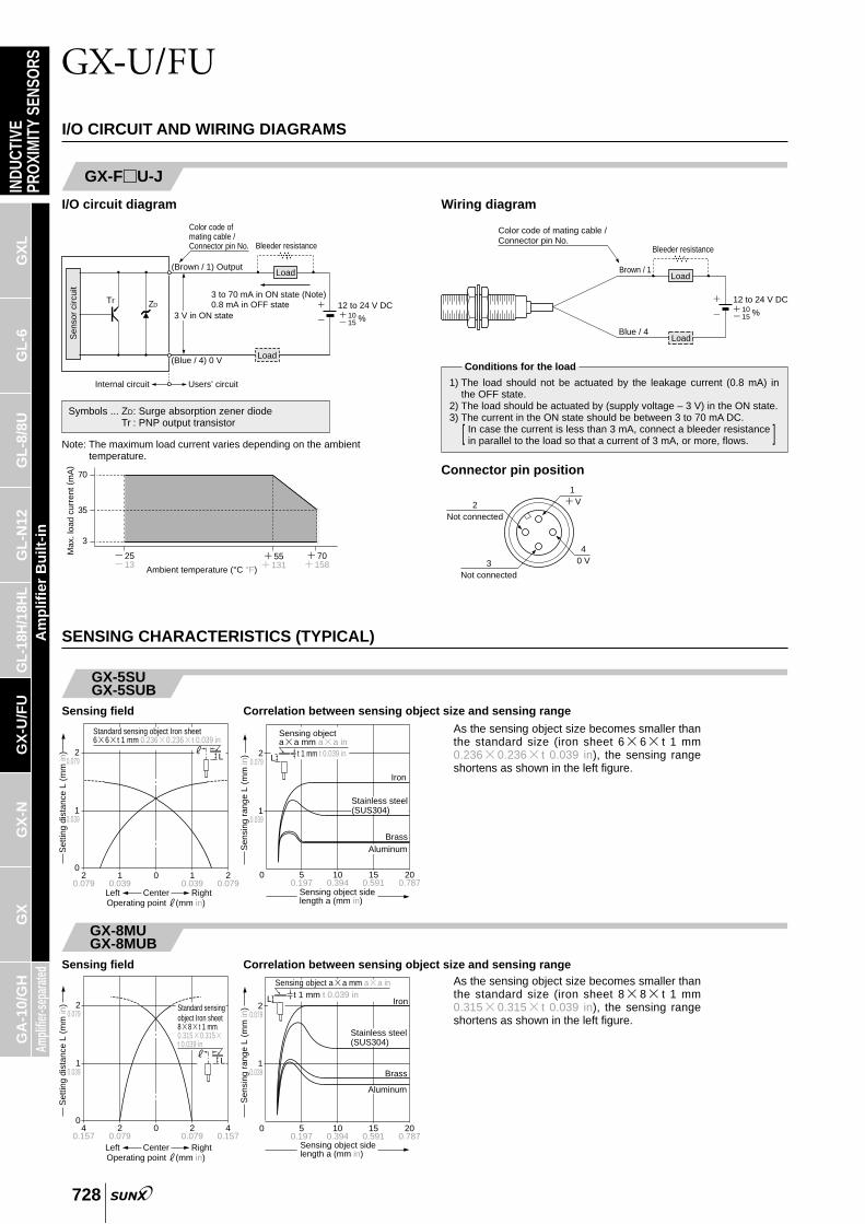
I/O CIRCUIT AND WIRING DIAGRAMS
GX-U(B)
I/O circuit diagram
Note: The maximum load current varies depending on the ambienttemperature.
Wiring diagram
Users’ circuitInternal circuit
Sen
sor
circ
uit
(Brown) Output
Color code
Tr
(Blue) 0 V
ZD
Load
Load
Bleeder resistance
3 to 70 mA in ON state (Note)0.8 mA in OFF state
3 V in ON state12 to 24 V DC10 %15
12 to 24 V DC10 %15
Brown
BlueLoad
Load
Bleeder resistance
Symbols ... ZD: Surge absorption zener diodeTr : PNP output transistor
70
3
35
2513
55131
70158
Max
. loa
d cu
rren
t (m
A)
Ambient temperature (°C °F)
1) The load should not be actuated by the leakage current (0.8 mA) inthe OFF state.
2) The load should be actuated by (supply voltage – 3 V) in the ON state.3) The current in the ON state should be between 3 to 70 mA DC.
In case the current is less than 3 mA, connect a bleeder resistancein parallel to the load so that a current of 3 mA, or more, flows.[ ]
Conditions for the load
GX-U(B)-J
I/O circuit diagram Wiring diagram
Sen
sor
circ
uit
Tr ZD
(Brown) Output
Load
Bleeder resistance
Load
3 to 70 mA in ON state (Note)0.8 mA in OFF state
3 V in ON state
Users’ circuitInternal circuit
12 to 24 V DC10 %15
(Black) 0 V
Color code of mating cable
12 to 24 V DC10%15
Brown
BlueLoad
Load
Bleeder resistanceColor code of mating cable
1) The load should not be actuated by the leakage current (0.8 mA) inthe OFF state.
2) The load should be actuated by (supply voltage – 3 V) in the ON state.3) The current in the ON state should be between 3 to 70 mA DC.
In case the current is less than 3 mA, connect a bleeder resistancein parallel to the load so that a current of 3 mA, or more, flows.[ ]
Conditions for the load
Symbols ... ZD: Surge absorption zener diodeTr : PNP output transistor
70
3
35
2513
55131
70158
Max
. loa
d cu
rren
t (m
A)
Ambient temperature (°C °F)
Note: The maximum load current varies depending on the ambienttemperature. Connector pin position
GX-U-J (Normally open)
GX-UB-J (Normally closed)
20.079
10.039
40.157
02
0.0790 2
0.0794
0.157Left RightCenterOperating point ?(mm in)
Set
ting
dist
ance
L (
mm
in)
#L
Standard sensing object Iron sheet88t 1 mm0.3150.315t 0.039 in
70
3
35
2513
55131
70158
Max
. loa
d cu
rren
t (m
A)
Ambient temperature (°C °F)
I/O CIRCUIT AND WIRING DIAGRAMS
SENSING CHARACTERISTICS (TYPICAL)
GX-5SUGX-5SUB
Sensing field Correlation between sensing object size and sensing range
20.079
10.039
20.079
01
0.0390 1
0.0392
0.079
#L
Standard sensing object Iron sheet 66t 1 mm 0.2360.236t 0.039 in
Left RightCenterOperating point ?(mm in)
Set
ting
dist
ance
L (
mm
in) 2
0.079
10.039
0 50.197
100.394
150.591
200.787
BrassAluminum
Stainless steel(SUS304)
L
Sensing object aa mm aa in
t 1 mm t 0.039 in
Sen
sing
ran
ge L
(m
m in
)
Sensing object side length a (mm in)
Iron
As the sensing object size becomes smaller thanthe standard size (iron sheet 66t 1 mm0.2360.236t 0.039 in), the sensing rangeshortens as shown in the left figure.
INDU
CTIV
EPR
OXI
MIT
YSE
NSO
RSG
XL
GL
-6G
L-8
/8U
GL
-N12
GL-
18H
/18H
LG
X-U
/FU
GX
-NG
XAm
plifie
r-sep
arate
dA
mp
lifie
r B
uilt
-in
GA
-10/
GH
GX-U/FU
728
Note: The maximum load current varies depending on the ambienttemperature.
I/O circuit diagram Wiring diagram
Users’ circuitInternal circuit
Sen
sor
circ
uit
(Brown / 1) Output
Color code of mating cable /Connector pin No.
Tr
(Blue / 4) 0 V
ZD
Load
Load
Bleeder resistance
3 to 70 mA in ON state (Note)0.8 mA in OFF state
3 V in ON state12 to 24 V DC10 %15
Symbols ... ZD: Surge absorption zener diodeTr : PNP output transistor
GX-FU-J
12 to 24 V DC10 %15
Blue / 4Load
Load
Bleeder resistance
Brown / 1
Color code of mating cable /Connector pin No.
1) The load should not be actuated by the leakage current (0.8 mA) inthe OFF state.
2) The load should be actuated by (supply voltage – 3 V) in the ON state.3) The current in the ON state should be between 3 to 70 mA DC.
In case the current is less than 3 mA, connect a bleeder resistancein parallel to the load so that a current of 3 mA, or more, flows.[ ]
Conditions for the load
Connector pin position1
V2Not connected
3Not connected
40 V
GX-8MUGX-8MUB
Sensing field Correlation between sensing object size and sensing range
20.079
10.039
0 50.197
100.394
150.591
200.787
Brass
Aluminum
Stainless steel(SUS304)
L
Sensing object aa mm aa int 1 mm t 0.039 in
Iron
Sen
sing
ran
ge L
(m
m in
)
Sensing object side length a (mm in)
As the sensing object size becomes smaller thanthe standard size (iron sheet 88t 1 mm0.3150.315t 0.039 in), the sensing rangeshortens as shown in the left figure.

INDU
CTIV
EPR
OXI
MIT
YSE
NSO
RSG
XL
GL
-6G
L-8
/8U
GL
-N12
GL-
18H
/18H
LG
X-U
/FU
GX
-NG
XAm
plifie
r-sep
arate
dA
mp
lifie
r B
uilt
-in
GA
-10/
GH
GX-U/FU
729
SENSING CHARACTERISTICS (TYPICAL)
GX-12MU GX-12MUBGX-F12MU-J
Sensing field Correlation between sensing object size and sensing range
Left RightCenterOperating point #(mm in)
40.157
20.079
0 20.079
40.157
0
20.079
40.157
Set
ting
dist
ance
L (
mm
in) #
L
Standard sensing object Iron sheet 1212t 1 mm 0.4720.472t 0.039 mm
40.157
20.079
0 100.394
200.787
301.181
401.575
BrassAluminum
Stainless steel(SUS304)
L
Sensing object aa mm aa int 1 mm t 0.039 in
IronS
ensi
ng r
ange
L (
mm
in)
Sensing object side length a (mm in)
As the sensing object size becomes smaller thanthe standard size (iron sheet 1212t 1 mm0.4720.472t 0.039 in), the sensing rangeshortens as shown in the left figure.
GX-18MU GX-18MUBGX-F18MU-J
Sensing field Correlation between sensing object size and sensing range
Left RightCenterOperating point #(mm in)
200.787
100.394
0 100.394
200.787
0
50.197
100.394
Set
ting
dist
ance
L (
mm
in) #
L
Standard sensing object Iron sheet 1818t 1 mm 0.7090.709t 0.039 in
100.394
50.197
0 100.394
200.787
301.181
401.575
BrassAluminum
Stainless steel(SUS304)
L
Sensing object aa mm aa int 1 mm t 0.039 in
Iron
Sen
sing
ran
ge L
(m
m in
)
Sensing object side length a (mm in)
As the sensing object size becomes smaller thanthe standard size (iron sheet 1818t 1 mm0.7090.709t 0.039 in), the sensing rangeshortens as shown in the left figure.
GX-30MU GX-30MUBGX-F30MU-J
Sensing field Correlation between sensing object size and sensing range
Left RightCenterOperating point #(mm in)
200.787
100.394
0 100.394
200.787
0
50.197
100.394
Set
ting
dist
ance
L (
mm
in) #
L
Standard sensing object Iron sheet 3030t 1 mm 1.1811.181t 0.039 in
100.394
50.197
0 200.787
401.575
602.362
803.150
Aluminum
Stainless steel(SUS304)
Brass
L
Sensing object aa mm aa int 1 mm t 0.039 in
Iron
Sen
sing
ran
ge L
(m
m in
)
Sensing object side length a (mm in)
As the sensing object size becomes smaller thanthe standard size (iron sheet 3030t 1 mm1.1811.181t 0.039 in), the sensing rangeshortens as shown in the left figure.
GX-8MLUGX-8MLUB
Sensing field Correlation between sensing object size and sensing range
40.157
20.079
100.394
05
0.1970 5
0.19710
0.394Left RightCenterOperating point ?(mm in)
Set
ting
dist
ance
L (
mm
in)
#L
Standard sensing object Iron sheet2020t 1 mm0.7870.787t 0.039 in
40.157
20.079
0 100.394
200.787
301.181
401.575
Brass
Stainless steel(SUS304)
L
Sensing object aa mm aa int 1 mm t 0.039 in
Iron
Sen
sing
ran
ge L
(m
m in
)
Sensing object side length a (mm in)
Aluminum
As the sensing object size becomes smaller thanthe standard size (iron sheet 2020t 1 mm0.7870.787t 0.039 in), the sensing rangeshortens as shown in the left figure.

INDU
CTIV
EPR
OXI
MIT
YSE
NSO
RSG
XL
GL
-6G
L-8
/8U
GL
-N12
GL-
18H
/18H
LG
X-U
/FU
GX
-NG
XAm
plifie
r-sep
arate
dA
mp
lifie
r B
uilt
-in
GA
-10/
GH
GX-U/FU
730
GX-12MLUGX-12MLUB
Sensing field Correlation between sensing object size and sensing range
Left RightCenterOperating point #(mm in)
200.787
100.394
0 100.394
200.787
0
50.197
100.394
Set
ting
dist
ance
L (
mm
in) #
L
Standard sensing object Iron sheet 3030t 1 mm 1.1811.181t 0.039 mm
100.394
50.197
0 200.787
401.575
602.362
803.150
L
Sensing object aa mm aa int 1 mm t 0.039 in
Brass
Stainless steel(SUS304)
Sen
sing
ran
ge L
(m
m in
)
Sensing object side length a (mm in)
Aluminum
Iron
As the sensing object size becomes smaller thanthe standard size (iron sheet 3030t 1 mm1.1811.181t 0.039 in), the sensing rangeshortens as shown in the left figure.
GX-18MLUGX-18MLUB
Sensing field Correlation between sensing object size and sensing range
Left RightCenterOperating point #(mm in)
200.787
100.394
0 100.394
200.787
0
100.394
200.787
Set
ting
dist
ance
L (
mm
in) #
L
Standard sensing object Iron sheet 5050t 1 mm 1.9691.969t 0.039 in
200.787
100.394
0 200.787
401.575
602.362
803.150
Brass
Stainless steel(SUS304)
L
Sensing object aa mm aa int 1 mm t 0.039 in
Sen
sing
ran
ge L
(m
m in
)
Sensing object side length a (mm in)
Aluminum
Iron
As the sensing object size becomes smaller thanthe standard size (iron sheet 5050t 1 mm1.9691.969t 0.039 in), the sensing rangeshortens as shown in the left figure.
GX-30MLUGX-30MLUB
Sensing field Correlation between sensing object size and sensing range
Left RightCenterOperating point #(mm in)
200.787
100.394
0 100.394
200.787
0
100.394
200.787
Set
ting
dist
ance
L (
mm
in)
#L
Standard sensing object Iron sheet 7070t 1 mm2.7562.756t 0.039 in
200.787
100.394
0 200.787
401.575
602.362
803.150
Brass
Stainless steel(SUS304)
L
Sensing object aa mm aa int 1 mm t 0.039 in
Iron
Sen
sing
ran
ge L
(m
m in
)
Sensing object side length a (mm in)
Aluminum
As the sensing object size becomes smaller thanthe standard size (iron sheet 7070t 1 mm2.7562.756t 0.039 in), the sensing rangeshortens as shown in the left figure.
SENSING CHARACTERISTICS (TYPICAL)

Model No.
19 0.748
20 0.787
35 1.378
70 2.756
115 4.528
60 2.362
145 5.709
250 9.843
350 13.780
14 0.551
15 0.591
20 0.787
45 1.772
70 2.756
45 1.772
95 3.740
165 6.496
250 9.843
G (mm in) H (mm in)
GX-5SU(B)
GX-8MU(B)
GX-12MU(B)GX-F12MU-J
GX-18MU(B)GX-F18MU-J
GX-30MU(B)GX-F30MU-J
GX-8MLU(B)
GX-12MLU(B)
GX-18MLU(B)
GX-30MLU(B)
Model No. E (mm in)
"12 "0.472
"24 "0.945
"50 "1.969
"75 "2.953
"105 "4.134
F (mm in)
3 0.118
12 0.472
15 0.591
25 0.984
30 1.181
GX-5SU(B)
GX-8MLU(B)
GX-12MLU(B)
GX-18MLU(B)
GX-30MLU(B)
4.5 0.177
4.5 0.177
8 0.315
20 0.787
40 1.575
8 0.315
22 0.866
45 1.772
75 2.953
Model No.
GX-5SU(B)
GX-8MU(B)
GX-12MU(B)GX-F12MU-J
GX-18MU(B)GX-F18MU-J
GX-30MU(B)GX-F30MU-J
GX-8MLU(B)
GX-12MLU(B)
GX-18MLU(B)
GX-30MLU(B)
D (mm in)
5.9 N m
11.8 N m
10 N m
20 N m
45 N m
80 N m
80 N m
180 N m
11.8 N m
20 N m
80 N m
180 N m
INDU
CTIV
EPR
OXI
MIT
Y SE
NSO
RSG
XL
GL
-6G
L-8
/8U
GL
-N12
GL-
18H
/18H
LG
X-U
/FU
GX
-NG
XAm
plifie
r-sep
arate
dA
mp
lifie
r B
uilt
-in
GA
-10/
GH
GX-U/FU
731
PRECAUTIONS FOR PROPER USE Refer to p.1152l for general precautions.
This product is not a safety sensor. Its use is notintended or designed to protect life and prevent bodyinjury or property damage from dangerous parts ofmachinery. It is a normal object detection sensor.
Mounting• The tightening torque should be under the value givenbelow.
Distance from surrounding metal• As metal around the sensor may affect the sensingperformance, pay attention to the following points.
Mutual interference• When two or more sensors are installed in parallel or faceto face, keep the minimum separation distance specifiedbelow to avoid mutual interference.
• The surrounding metal will affect the sensing per-formance. Keep the minimum distance specified in thetable below.
• Sensing range may decrease if the sensor is completelyembedded in metal. Especially for the non-threaded typeand the non-shielded type, keep the minimum distancespecified in the table below.
• Tighten with the cup-point of a set screw (M4 or less).
Mounting with a set screw
Operation indicator
Setscrew
Operation indicator
Operation indicator
B
A
Set screw(M4 or less) Model No.
GX-5SU(B)
A (mm in)
5 to 300.197 to 1.181
B (mm in)
3 0.118
Tightening torque
0.78 Nm
Mounting with nut
<Shielded threaded type> <Non-shielded threaded type>
C
Attached toothed lock washer
Mounting plate
CAttached toothed lock washer
Mounting plate
Model No.
GX-8MU(B)
GX-8MLU(B)
GX-12MLU(B)
GX-18MLU(B)
GX-30MLU(B)
GX-12MU(B)GX-F12MU-J
GX-18MU(B)GX-F18MU-J
GX-30MU(B)GX-F30MU-J
Dimension C (mm in)
3 to 10.3 0.118 to 0.406
10.3 0.406 or more
3.5 to 13.5 0.138 to 0.531
13.5 0.531 or more
4 to 18 0.157 to 0.709
18 0.709 or more
5 to 21 0.197 to 0.827
21 0.827 or more
12 0.472 or more
15 0.591 or more
25 0.984 or more
30 1.181 or more
Tightening torque
Influence of surrounding metal
D
Bac
kgro
und
met
al
Embedding of the sensor in metal
E
FMetal
Note: With the non-shielded type, the sensing range may vary dependingon the position of the nuts.
Face to face mounting
Parallel mounting
G
H
Note: Mount such that the nuts do not protrude from the threaded portion.
<Non-threaded type>
• Do not fix on the operation indicator or opposite to it.

INDU
CTIV
EPR
OXI
MIT
Y SE
NSO
RSG
XL
GL
-6G
L-8
/8U
GL
-N12
GL-
18H
/18H
LG
X-U
/FU
GX
-NG
XAm
plifie
r-sep
arate
dA
mp
lifie
r B
uilt
-in
GA
-10/
GH
GX-U/FU
732
PRECAUTIONS FOR PROPER USE Refer to p.1152l for general precautions.
Sensing range• The sensing range is specified for the standard sensingobject. With a non-ferrous metal, the sensing range isobtained by multiplying with the correction coefficientspecified below.
Wiring• The sensor must be connected to a power supply via a
load. If the sensor is connected to a power supply without aload, the short-circuit protection makes the sensor inoperable.(The output stays in the OFF state and the indicator doesnot light up.) In this case, rectify by connecting the powersupply via a load. Now, the sensor becomes operable.Further, take care that if the power supply is connected withreverse polarity without a load, the sensor will get damaged.
2-color indicator (Normally open type only)• When the sensing object is in the stable sensing range,the LED lights up in green, and when the sensing object isin the unstable sensing range, the LED lights up inorange. While the LED lights up in green, the sensing isperformed stably without being affected by temperaturedrifts or voltage fluctuations.
• For series connection (AND circuit) or parallel connection(OR circuit) of sensors, take care of the following.
• The residual voltage of the sensor is 3 V. Before connect-ing a relay as the load, take care of its actuation voltage.(Some 12 V relays may not be usable.)
Series connection (AND circuit) Parallel connection (OR circuit)
Protection cover (Optional)• It protects the sensing surface from welding sparks (spat-ter), etc.
Others• Do not use during the initial transient time (50 ms) afterthe power supply is switched on.
• When the sensor is mounted on a moving base, stressshould not be applied to the sensor cable joint.
Note: The sensing range also changes if the sensing object is plated.
Note: Mount the protection cover so that there is no gap between it and thesensing surface.
Correction coefficient
GX-5SU(B)
GX-8MU(B)
GX-12MU(B)GX-F12MU-J
GX-18MU(B)GX-F18MU-J
GX-30MU(B)GX-F30MU-J
GX-8MLU(B)
GX-12MLU(B)
GX-18MLU(B)
GX-30MLU(B)
1
1
1
1
1
1
1
1
1
IronMetal
Model No.Stainless steel(SUS304) Brass Aluminum
0.63 approx.
0.59 approx.
0.75 approx.
0.75 approx.
0.69 approx.
0.64 approx.
0.67 approx.
0.68 approx.
0.67 approx.
0.32 approx.
0.32 approx.
0.51 approx.
0.50 approx.
0.44 approx.
0.38 approx.
0.44 approx.
0.45 approx.
0.44 approx.
0.30 approx.
0.29 approx.
0.49 approx.
0.48 approx.
0.42 approx.
0.38 approx.
0.43 approx.
0.43 approx.
0.43 approx.
Mounting method
Protection cover Sensor
Material: Fluorine resin
Model No.
MS-H12
MS-H18
MS-H30
Applicable model No.
GX-12MU(B)
GX-18MU(B)
GX-30MU(B)
Stress Stress
Brown lead wire
Blue lead wire
DCpowersupply
Blue lead wire
Brown lead wire
DCpowersupply
Load
VRL
VCCBlue lead wire
Brown lead wire
Blue lead wire
Brown lead wire
ICC
(IL)
Load
VCC
Brown lead wire
Blue lead wire
Bluelead wire
Brownlead wire
12 V DC power supply
VR Relay actuation voltage
Vs3 V
Brown lead wire
Blue lead wire
Rel
ay
Residual voltagewhen the sensoris in the ON state
Relay actuation voltage:VR h123 V
h9 V
Unstable range
LED
light
sup
in g
reen
Sw
itche
d O
N
2-color indicator operation
Output operation
0
Max.operation distance
Set
ting
dist
ance Output operation
level
LED lights upin orange
Sw
itche
d O
FF
Ligh
ts O
FF
When all sensors are in the ON state,the load voltage VRL is given by:VRLVCCn3 (V)
Vcc: supply voltage(24 V DC max.)
n: number of sensors
Make sure that the load can workproperly at this voltage.
Note: The output is generated nor-mally even if the indicatordoes not light up properly.
When all sensors are in the OFF state,the load leakage current lcc is given by:
lccn0.8 (mA) (n: number of sensors)
Make sure that the load can work properly.
Note: The load current in the ON stateis given by:
ILVcc3 V
(mA)Load resistance
The load current must be3 mAn h IL h 70 mA(n: number of sensors turned ON)

INDU
CTIV
EPR
OXI
MIT
YSE
NSO
RSG
XL
GL
-6G
L-8
/8U
GL
-N12
GL-
18H
/18H
LG
X-U
/FU
GX
-NG
XAm
plifie
r-sep
arate
dA
mp
lifie
r B
uilt
-in
GA
-10/
GH
GX-U/FU
733
GX-5SUGX-5SUB Sensor
DIMENSIONS (Unit: mm in) The CAD data in the dimensions can be downloaded from the SUNX website: http://www.sunx.co.jp/
40.157
"5.4"0.213
"2.9 "0.114 cable, 2 m 6.562 ft long
1.50.059
301.181
16.50.650
2-color indicator (Orange, green) (Note)
Note: Normally closed type has an operation indicator (orange) instead ofthe 2-color indicator.
GX-12MUGX-12MUB Sensor
"3.6 "0.142 cable, 2 m 6.562 ft long
170.669
"21"0.827
"10.4"0.409
"5.5"0.217
2-color indicator (Orange, green) (Note)
1.30.051
3.50.138
35.51.398
20.079
50.197
M121 0.039
Toothed lock washer(Internally toothed)
Indicator part
Note: Normally closed type has an operation indicator (orange) instead ofthe 2-color indicator.
GX-18MUGX-18MUB Sensor
240.945
"29"1.142
"10.4"0.409
"5.5"0.217
M181 0.039
2-color indicator (Orange, green) (Note)
1.30.051
40.157
36.51.437
20.079
50.197
"3.6 "0.142 cable,2 m 6.562 ft long
Toothed lock washer(Internally toothed)
Indicator part
Note: Normally closed type has an operation indicator (orange) instead ofthe 2-color indicator.
GX-30MUGX-30MUB Sensor
361.417
"43"1.693
39.51.555
20.079
M301.5 0.059
50.197
"10.4"0.409
"5.5"0.217
1.30.051
50.197
2-color indicator (Orange, green) (Note)
"3.6 "0.142 cable, 2 m 6.562 ft long
Toothed lock washer(Internally toothed)
Indicator part
Note: Normally closed type has an operation indicator (orange) instead ofthe 2-color indicator.
GX-8MLUGX-8MLUB Sensor
30.118
60.236
"6.8"0.268
"6.5"0.256"15
"0.591
200.787
100.394
120.472 M81 0.039
Toothed lock washer(Internally toothed) "2.9 "0.114 cable, 2 m 6.562 ft long
2-color indicator (Orange, green) (Note)
Indicator part
Note: Normally closed type has an operation indicator (orange) instead ofthe 2-color indicator.
GX-12MLUGX-12MLUB Sensor
170.669
"21 "0.827
"10.4"0.409
"5.5"0.217
1.30.051
35.51.398
20.079
50.197
M121 0.039
3.50.138
"10.2"0.402
70.276
2-color indicator (Orange, green) (Note)
"3.6 "0.142 cable, 2 m 6.562 ft long
Toothed lock washer(Internally toothed)
Indicator part
Note: Normally closed type has an operation indicator (orange) instead ofthe 2-color indicator.
GX-18MLUGX-18MLUB
GX-12MU-J GX-12MUB-JGX-F12MU-J
Sensor
240.945
"29 "1.142
"10.4"0.409
"5.5"0.217
1.30.051
36.51.437
20.079
50.197
M181 0.039
"15.2"0.598
40.157
100.394
2-color indicator (Orange, green) (Note)
"3.6 "0.142 cable,2 m 6.562 ft long
Toothed lock washer(Internally toothed)
Indicator part
Note: Normally closed type has an operation indicator (orange) instead ofthe 2-color indicator.
GX-30MLUGX-30MLUB Sensor
361.417
"43 "1.693
"10.4"0.409
"5.5"0.217
39.51.555
20.079
M301.5 0.059
50.197
"26.6"1.047
1.30.051
50.236
120.472
2-color indicator (Orange, green) (Note)
"3.6 "0.142 cable,2 m 6.562 ft long
Toothed lock washer(Internally toothed)
Indicator part
Note: Normally closed type has an operation indicator (orange) instead ofthe 2-color indicator.
Sensor
170.669
"21"0.827 "5.5
"0.2173.50.138
35.51.398 2
0.079
50.197
"10.4"0.409
"14"0.551
(300)(11.811) 44
1.732
1.30.051
"3.6 "0.142 cable 2-color indicator(Orange, green)
M12 connector
M121 0.039
Toothed lock washer(Internally toothed)
Indicator part
GX-8MUGX-8MUB Sensor
30.118
"6.8"0.268
"15"0.591
M81 0.039
"2.9 "0.114 cable, 2 m 6.562 ft long
200.787
100.394
120.472
Toothed lock washer(Internally toothed)
2-color indicator (Orange, green) (Note)
Indicator part
Note: Normally closed type has an operation indicator (orange) instead ofthe 2-color indicator.
Note: Normally closed type has an operation indicator (orange) instead ofthe 2-color indicator.

5
6
8
MS-H12
MS-H18
MS-H30
Model No.
Symbol
"11.5"0.453
"17.5"0.689
"29.4"1.157
"14"0.551
"20"0.787
"33"1.299
GX-12MU(B)
GX-18MU(B)
GX-30MU(B)
A B C Applicablemodel No.
INDU
CTIV
EPR
OXI
MIT
YSE
NSO
RSG
XL
GL
-6G
L-8
/8U
GL
-N12
GL-
18H
/18H
LG
X-U
/FU
GX
-NG
XAm
plifie
r-sep
arate
dA
mp
lifie
r B
uilt
-in
GA
-10/
GH
GX-U/FU
734
Sensor
1.30.051
240.945
"29"1.142
40.157
36.51.437 2
0.079
50.197
"5.5"0.217
"10.4"0.409
"14"0.551
(300)(11.811) 44
1.732M181 0.039
Toothed lock washer(Internally toothed)
"3.6 "0.142 cable2-color indicator(Orange, green)
M12 connector
Indicator part
Sensor
361.417
"43"1.693
39.51.555
M301.5 0.059
50.197
50.197
20.079
"3.6 "0.142 cable
"5.5"0.217
"10.4"0.409
"14"0.551
(300)(11.811) 44
1.732
2-color indicator(Orange, green)
1.30.051
M12 connector
Toothed lock washer(Internally toothed)
Indicator part
MS-SS5 Sensor mounting bracket for GX-5SU(B) (Optional)
4 0.157
40.157
40.157
8.30.327
6.10.240
2-"3.5 "0.138 mounting holes
180.709
100.394
160.630
80.315
MS-H12 MS-H18MS-H30 Protection cover (Optional)
A
B C
0.7 00.2
0.028 00.008
Thickness of front face
DIMENSIONS (Unit: mm in) The CAD data in the dimensions can be downloaded from the SUNX website: http://www.sunx.co.jp/
Material: Nylon 66
Material: Fluorine resin
Note: Normally closed type has an operation indicator (orange) instead ofthe 2-color indicator.
Note: Normally closed type has an operation indicator (orange) instead ofthe 2-color indicator.
Sensor
1.30.051
170.669
"21 "0.827
3.50.138
70.276
35.51.398 2
0.079
50.197
"5.5"0.217
"10.4"0.409
"10.2"0.402
"14"0.551
(300)(11.811)
441.732M121 0.039
Toothed lock washer(Internally toothed)
"3.6 "0.142 cable2-color indicator(Orange, green) (Note)
M12 connector
Indicator part
Sensor
1.30.051
240.945
"29 "1.142
40.157
100.394
36.51.437 2
0.079
50.197
"5.5"0.217
"10.4"0.409
"15.2"0.598
"14"0.551
(300)(11.811) 44
1.732M181 0.039
Toothed lock washer(Internally toothed)
"3.6 "0.142 cable2-color indicator(Orange, green)(Note)
M12 connector
Indicator part
Note: Normally closed type has an operation indicator (orange) instead ofthe 2-color indicator.
Note: Normally closed type has an operation indicator (orange) instead ofthe 2-color indicator.
Sensor
1.30.051
361.417
"26.6"1.047
"43"1.693
120.472
39.51.555 2
0.079
50.197
50.197
"5.5"0.217
"10.4"0.409
"14"0.551
(300)(11.811) 44
1.732M301.5 0.059
Toothed lock washer(Internally toothed)
"3.6 "0.142 cable 2-color indicator(Orange, green)(Note)
M12 connector
Indicator part
Note: Normally closed type has an operation indicator (orange) instead ofthe 2-color indicator.
GX-12MLU-JGX-12MLUB-J
GX-18MLU-JGX-18MLUB-J
GX-30MLUGX-30MLUB
GX-18MU-J GX-18MUB-JGX-F18MU-J
GX-30MU-J GX-30MUB-JGX-F30MU-J
Top Related