


Languages
Pages
Legal

Guide to modern insulation testing
Code No. 20 750 784
Guide to modern insulation testing Table of contents
2
1. Introduction .................................................................................................. 3 1.1 Purpose of the handbook »Guide to modern insulation testing« .............. 3 1.2 Presentation of company METREL d.d. and its production program ........ 4
2. The origin of insulation................................................................................ 5 2.1 Basics of insulation measurements .......................................................... 6
2.1.1 Surface leakage current IRiss.............................................................. 7 2.1.2 Insulation leakage current IRiso .......................................................... 7 2.1.3 Polarization absorption current IRCpi .................................................. 7 2.1.4 Capacitance charging current ICiso..................................................... 7 2.1.5 Total current Itot .................................................................................. 8
2.2 Resume.................................................................................................... 9 3. Types of insulation testing ........................................................................ 10
3.1 DC voltage testing and AC voltage testing ............................................. 10 3.2 Spot reading test .....................................................................................11 3.3 Time rise method / polarization index / dielectric absorption .................. 12 3.4 Dielectric discharge ................................................................................ 14 3.5 Step voltage insulation resistance test.................................................... 15 3.6 Withstanding voltage test ....................................................................... 16
4. Test set-up .................................................................................................. 18 4.1 Safety considerations ............................................................................. 18 4.2 Determination of tested devices ............................................................. 18 4.3 Discharging of capacitive objects after the test....................................... 21 4.4 Choosing appropriate test equipment..................................................... 22
5. Typical problems during measurements.................................................. 23 5.1 Result too low because of surface leakages, guarding techniques ........ 23 5.2 Influence of temperature......................................................................... 24 5.3 Influence of humidity .............................................................................. 26 5.4 Noisy environment, using filters.............................................................. 27 5.5 Instability because of high capacitive loads............................................ 29 5.6 Instability and accuracy problems of very high insulation results............ 30 5.7 Too-low result because of fixed wired and grounded objects ................. 31
6. Typical connections for insulation resistance testing ............................ 32 6.1 Power cables.......................................................................................... 32 6.2 Control and communication cable .......................................................... 33 6.3 Wiring installation ................................................................................... 35 6.4 Home appliances and similar electrical devices ..................................... 35 6.5 Induction motor....................................................................................... 36 6.6 Power transformer.................................................................................. 37
7. Interpretation of results ............................................................................. 39 8. Standards.................................................................................................... 41 9. Glossary...................................................................................................... 43 10. Recommended measurement instruments............................................. 45
Guide to modern insulation testing Introduction
3
1. Introduction Insulation and leaking are two terms tied up to each other in the technical world. Insulation is a material property and is measured as insulation resistance. Leaking is measured as leakage current in general and is a result of voltage (tension) applied to insulation. Characteristics of insulation tend to change through time, normally getting worse by ageing. Various physical phenomena have influence on insulation characteristics, like temperature, dirt, humidity, mechanical and electrical stresses, high-energy radiation, etc. Safety, operability, and reliability are the most important parameters of electrical device containing insulation and this is the reason why insulation has to be measured. Insulation is measured in the initiating phase of electrical device and also later during maintenance works or repairing, and measurements are of simple and diagnostic type. 1.1 Purpose of the handbook »Guide to modern insulation
testing« The intention of this hanbook is to better acquaint the reader with the extensive problematic of insulation measurements. The first part describes the basics of insulation measurement and terms that are regulating this field. A special attention is given to terms and definitions that users of measuring equipment meet daily. A special chapter is destined to the types of insulation testing. Another chapter covers typical problems during insulation measurement. We hope that chapters are written in a short and understandable manner. We expect that this document will serve the reader as a groundwork whenever he will deal with terms, parameters or standards of this field. The second part of the handbook acquaints the reader with the functions of METREL instruments. Presented are the most important connections for testing insulation resistance. The complete hapenning is shown, from the perception of the problem, the preparation and measurements itself, up to analysis and interpetation of final result. The third and last part shortly presents existing METREL instruments for measuring of insulation (Electronic Insulation Tester MA 2060, TeraOhm 5kV MI 2077). The glossary is given at the end of the book. A more complete information can be given by visiting our web site or by your local METREL distributor. The authors will be gratefull for every comment or additional suggestions that would help us to supplement the handbook and METREL products. This handbook together with user manuals of METREL instruments can be used for training on insulation measurement techniques, as well as for presentations of typical measuring instruments used today in the field of insulation measurements.
Guide to modern insulation testing Introduction
4
1.2 Presentation of company METREL d.d. and its production program
METREL, measuring and regulating equipment manufacturer has 42 years of experience in the development and production of measuring and regulating equipment. It is among the leading manufacturers and suppliers of test and measurement instruments for testing of safety on low-voltage electrical installations, earthing systems, testing of safety on machines and electrical appliances, instruments for measurement and testing of cable networks, as well as instruments for measurement, recording and analysing of power quality. 160 people are employed. There are 20 engineers involved in the R & D process. One of the superior aspects of METREL is the speed at which it completes its development projects so that it takes at most 12 months from the idea to the production of the first series. With regard to the construction of the test equipment, METREL has been linked up with University in Ljubljana and Ministry of science and technology. The results of our R & D activities are shown also in numerous patents registered, both at home and in other European countries. New products produced by METREL are launched on the market every year. In 2004 there will be 6 new measurement instruments coming from the production line. Each product is checked by calibration laboratory after completing the production process and the relevant calibration certificates are enclosed. METREL Calibration laboratory is internationally approved. METREL pays the greatest attention to the relationship with their partners and to the quality of its products. Certification to ISO 9001 has also been achieved and has been continuously maintained. The distribution network has been developed in most countries worldwide.
Guide to modern insulation testing The origin of insulation
5
2. The origin of insulation Modern technology brought us a lot of new materials, substances and other goods to make our life better and more comfortable. Electricity is one of them. However, many of these goods are useful only under control; otherwise, they are useless and could be dangerous. Common sense tells us that all these goods must be separated from surroundings – they must be insulated. For instance, to drive a car we have to drive gasoline within. We cannot imagine storing gasoline in a plastic bag. It must be stored in a special reservoir to prevent leaking. Gasoline must be reliably insulated from surroundings. The same is true with electricity. Electricity is very useful as long as it is "kept" inside the cables, busbars, winding… If the electricity "escapes" from these items it becomes useless and very dangerous. This is the reason why any item that carries electrical current is covered with some type of insulation. The insulation restricts the flow of current between different conductors and between conductors and ground. The insulation must be just the opposite from the conductor. The conductor is usually made from copper or aluminium, which is known to be a good conductor of electric current. The insulation is usually made from non-metallic material. It should resist current and keep the current in the path along the conductor.
In theory, insulation does not carry electrical current. However, in reality we do not have an ideal insulation material. Every kind of insulation has some resistance. The insulation resistance is very high but it is not infinite. Manufacturers of wires, cables, and motors have continually improved their insulation for service in industry, at home and other places, where electricity is being used. However, the insulation in service is subject to many effects which can cause it to fail: mechanical damage, vibration, excessive heat or cold, dirt, oil, and corrosive vapours moisture from air or technological process. Combination of electrical stresses and degradation of insulation are at work as time goes on. As pinholes or cracks develop, moisture and foreign matter penetrate the surfaces of the insulation, providing the low resistance path for leakage current. Once started, different degradation processes tend to aid each other, permitting excessive current through the insulation. The leaking current cannot be seen or smelt; only the consequences can be noticed - often too late. Usually, however, a drop in insulation resistance is gradual, giving plenty of warning if checked periodically. Such checks permit planned reconditioning before service failure. If there are no checks, the electric device with poor insulation may be dangerous to touch when voltage is applied and it can also be completely destroyed. A sudden drop in insulation resistance is very rare, for instance when a device is flooded. This is the reason why insulation-testing program should be carried out. A regular program of insulation resistance testing is strongly recommended to prevent electrical shocks, to assure safety of personnel, and to reduce out of service time. It helps to detect deterioration of insulation in order to schedule repair work such as: vacuum cleaning, steam cleaning, drying, and rewinding. It is also helpful for evaluating the quality of the repairs before the equipment is put back into operation.
Guide to modern insulation testing The origin of insulation
6
2.1 Basics of insulation measurements According to Ohms law,
RUI = Eq. 1
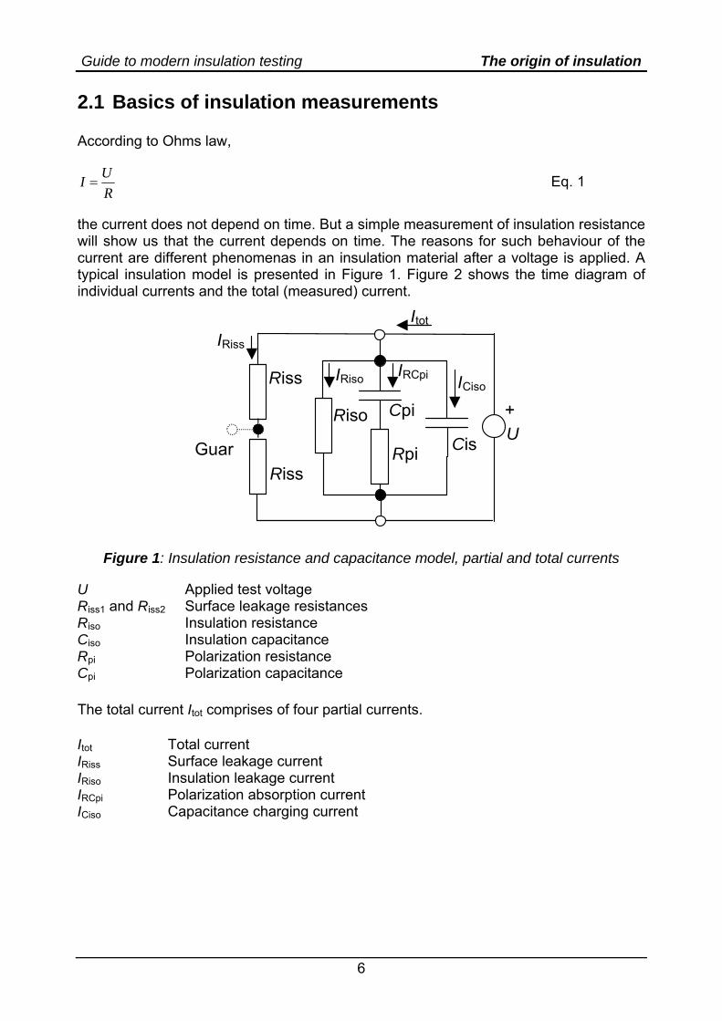
the current does not depend on time. But a simple measurement of insulation resistance will show us that the current depends on time. The reasons for such behaviour of the current are different phenomenas in an insulation material after a voltage is applied. A typical insulation model is presented in Figure 1. Figure 2 shows the time diagram of individual currents and the total (measured) current.
Riso Cpi
Rpi Cis
Riss
Riss
Itot
+
GuarU
ICisoIRCpiIRiso
IRiss
Figure 1: Insulation resistance and capacitance model, partial and total currents
U Applied test voltage Riss1 and Riss2 Surface leakage resistances Riso Insulation resistance Ciso Insulation capacitance Rpi Polarization resistance Cpi Polarization capacitance The total current Itot comprises of four partial currents. Itot Total current IRiss Surface leakage current IRiso Insulation leakage current IRCpi Polarization absorption current ICiso Capacitance charging current
Guide to modern insulation testing The origin of insulation
7
2.1.1 Surface leakage current IRiss Surface leakage current flows on the surface of insulation between connection points of applied voltage. This current causes an error in insulation resistance measurement and could be eliminated by using a guard terminal. According to Figure 1 it flows through resistors Riss1 and Riss2. The current does not depend on time.
iss2iss1Riss RR
UI+
= Eq. 2
2.1.2 Insulation leakage current IRiso This current flows through insulation. The insulation resists with resistance Riso (Figure 1). The insulation leakage current does not depend on time.
isoRiso R
UI = Eq. 3
2.1.3 Polarization absorption current IRCpi The absorption or de-absorption current starts from a lower level than capacitance charging current but has a much longer time constant (up to several minutes). This is caused by ions and dipoles re-aligning themselves within the insulation. When an electric field is applied some ions are able to move, and some dipoles align themselves within the field. These effects reverse themselves slowly when the test voltage is removed, caused by particles returning to their natural random state. In the model this phenomena is represented as an additional Rpi - Cpi combination in parallel with Riso. The current IRCpi charges the capacitor Cpi. At the beginning the capacitor is not charged, i.e. no polarized insulator, and the current starts with value U/Rpi. The capacitor starts to charge and the current becomes smaller. Finally the capacitor is completely charged, i.e., the insulator completely polarized, and the current does not flow any more. The polarization absorption current depends on time according to Equation 4.
pipi
piRCpi
CRt
eRUI
−= Eq. 4
Other currents could mask the polarization absorption current; therefore, the polarization current measurement could be problematic. It is often easier to measure the opposite process: the dielectric discharge. In this case the measurement starts with fully charged capacitor Cpi. The connection leads are shorted and the depolarization current is observed. 2.1.4 Capacitance charging current ICiso The capacitance charging current ICiso charges the capacitor Ciso. Ciso represents the capacitance between metal parts connected to the measuring instrument inputs that are
Guide to modern insulation testing The origin of insulation
8
separated with tested insulation. Only the test instrument internal resistance limits the ICiso.
isoint
intCiso
CRt
eRUI
−= Eq. 5
Rint is internal resistance of test source.
At the beginning the capacitor is not charged and high current is flowing. The current drops as the capacitor is being charged. 2.1.5 Total current Itot The sum of all presented currents represents the total current:
CisoRCpiRisoRisstot IIIII +++= Eq. 6
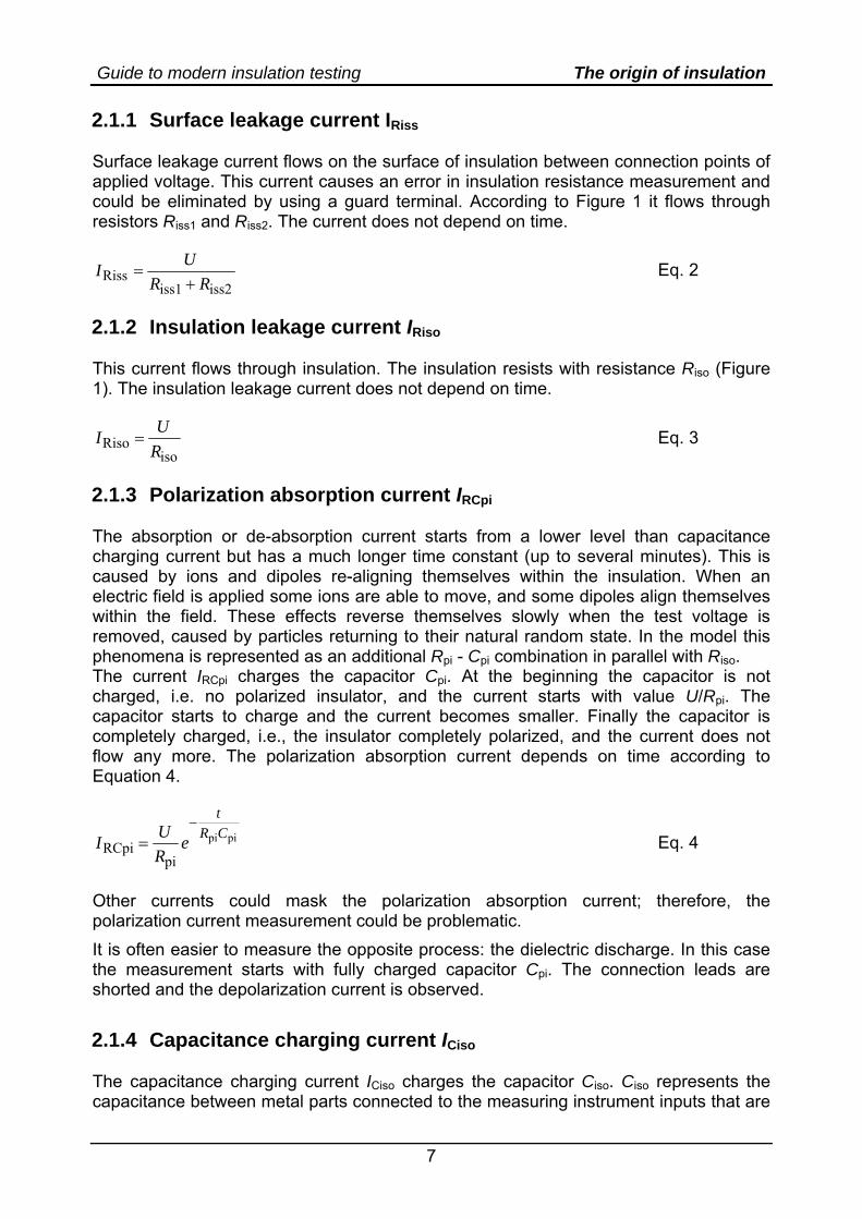
Figure 2 shows time diagram of the currents based on the standard insulation model presented in Figure 1.
ICiso IRCpi
IRiss
IRiso
Itot
t [s] 200 400 600 800
µA
0
10
20
30
40
Figure 2: Current diagram for an ideal voltage source
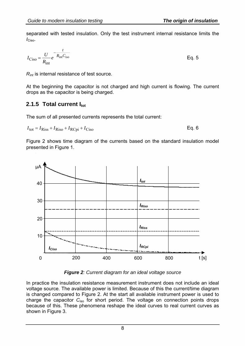
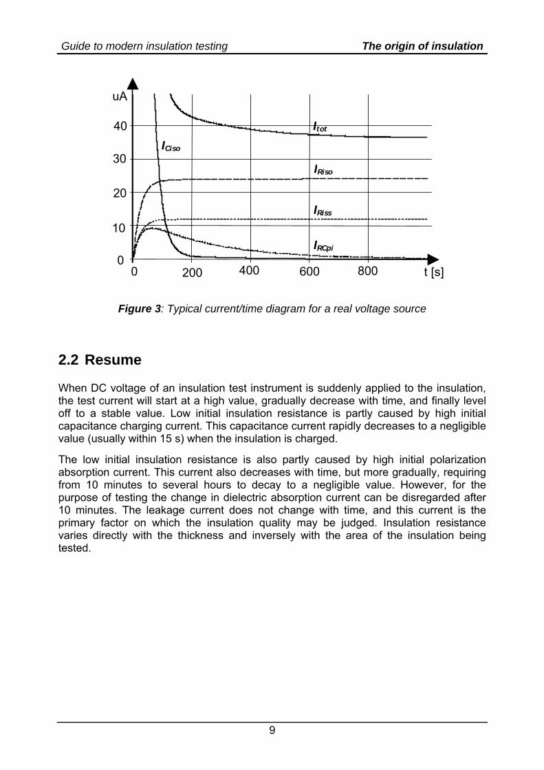
In practice the insulation resistance measurement instrument does not include an ideal voltage source. The available power is limited. Because of this the current/time diagram is changed compared to Figure 2. At the start all available instrument power is used to charge the capacitor Ciso for short period. The voltage on connection points drops because of this. These phenomena reshape the ideal curves to real current curves as shown in Figure 3.
Guide to modern insulation testing The origin of insulation
9
uA
0
10
20
30
40
t [s] 0 200 400 600 800
IRiso
Itot
IRiss
IRCpi
ICiso
Figure 3: Typical current/time diagram for a real voltage source
2.2 Resume When DC voltage of an insulation test instrument is suddenly applied to the insulation, the test current will start at a high value, gradually decrease with time, and finally level off to a stable value. Low initial insulation resistance is partly caused by high initial capacitance charging current. This capacitance current rapidly decreases to a negligible value (usually within 15 s) when the insulation is charged. The low initial insulation resistance is also partly caused by high initial polarization absorption current. This current also decreases with time, but more gradually, requiring from 10 minutes to several hours to decay to a negligible value. However, for the purpose of testing the change in dielectric absorption current can be disregarded after 10 minutes. The leakage current does not change with time, and this current is the primary factor on which the insulation quality may be judged. Insulation resistance varies directly with the thickness and inversely with the area of the insulation being tested.
Guide to modern insulation testing Types of insulation testing
10
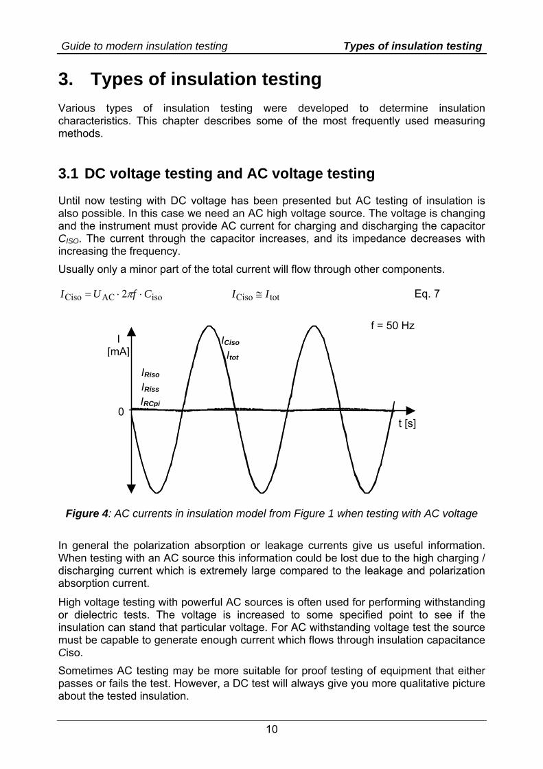
3. Types of insulation testing Various types of insulation testing were developed to determine insulation characteristics. This chapter describes some of the most frequently used measuring methods. 3.1 DC voltage testing and AC voltage testing Until now testing with DC voltage has been presented but AC testing of insulation is also possible. In this case we need an AC high voltage source. The voltage is changing and the instrument must provide AC current for charging and discharging the capacitor CISO. The current through the capacitor increases, and its impedance decreases with increasing the frequency. Usually only a minor part of the total current will flow through other components.
isoACCiso 2 CfUI ⋅⋅= π totCiso II ≅ Eq. 7
ICiso
IRCpi
IRiss
Itot
t [s]
f = 50 Hz I
[mA]
0
IRiso
Figure 4: AC currents in insulation model from Figure 1 when testing with AC voltage
In general the polarization absorption or leakage currents give us useful information. When testing with an AC source this information could be lost due to the high charging / discharging current which is extremely large compared to the leakage and polarization absorption current.
High voltage testing with powerful AC sources is often used for performing withstanding or dielectric tests. The voltage is increased to some specified point to see if the insulation can stand that particular voltage. For AC withstanding voltage test the source must be capable to generate enough current which flows through insulation capacitance Ciso. Sometimes AC testing may be more suitable for proof testing of equipment that either passes or fails the test. However, a DC test will always give you more qualitative picture about the tested insulation.
Guide to modern insulation testing Types of insulation testing
11
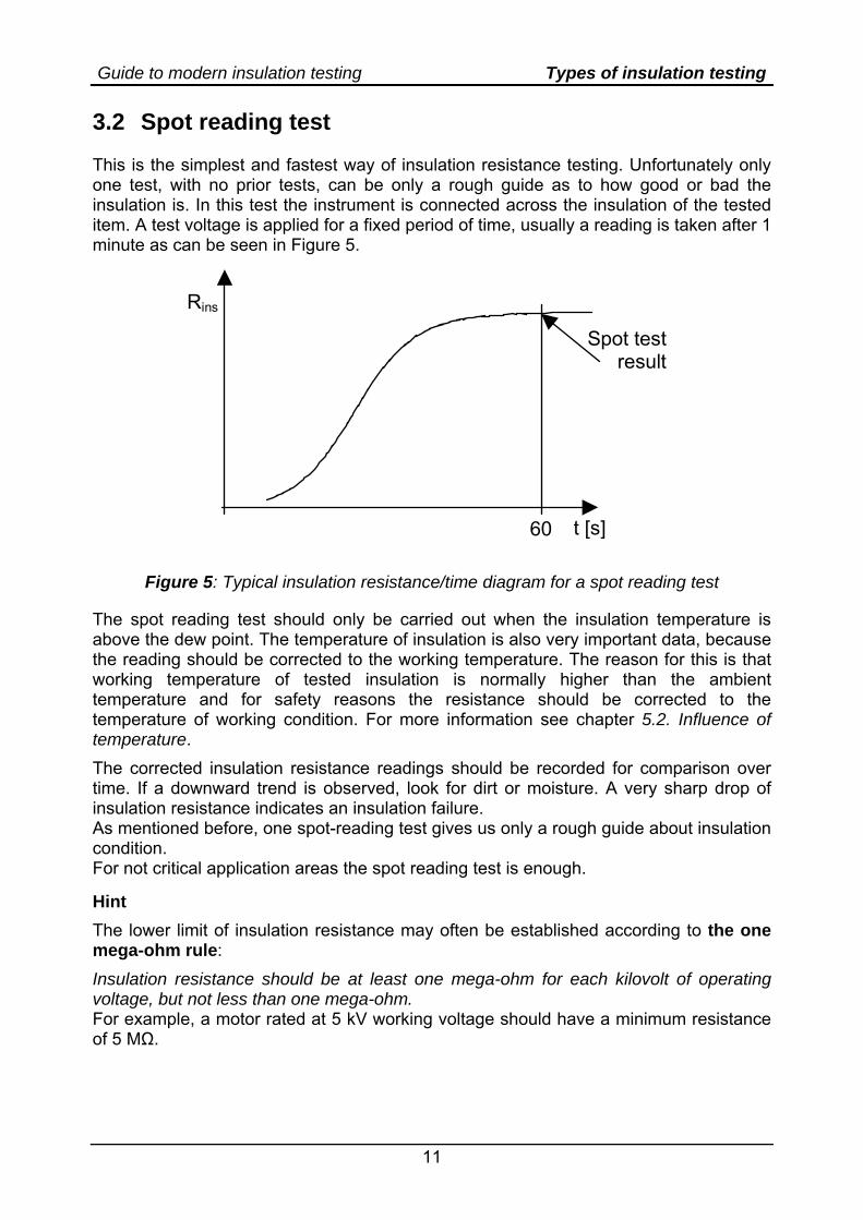
3.2 Spot reading test This is the simplest and fastest way of insulation resistance testing. Unfortunately only one test, with no prior tests, can be only a rough guide as to how good or bad the insulation is. In this test the instrument is connected across the insulation of the tested item. A test voltage is applied for a fixed period of time, usually a reading is taken after 1 minute as can be seen in Figure 5.
Spot test result
t [s] 60
Rins
Figure 5: Typical insulation resistance/time diagram for a spot reading test
The spot reading test should only be carried out when the insulation temperature is above the dew point. The temperature of insulation is also very important data, because the reading should be corrected to the working temperature. The reason for this is that working temperature of tested insulation is normally higher than the ambient temperature and for safety reasons the resistance should be corrected to the temperature of working condition. For more information see chapter 5.2. Influence of temperature. The corrected insulation resistance readings should be recorded for comparison over time. If a downward trend is observed, look for dirt or moisture. A very sharp drop of insulation resistance indicates an insulation failure. As mentioned before, one spot-reading test gives us only a rough guide about insulation condition. For not critical application areas the spot reading test is enough. Hint The lower limit of insulation resistance may often be established according to the one mega-ohm rule: Insulation resistance should be at least one mega-ohm for each kilovolt of operating voltage, but not less than one mega-ohm. For example, a motor rated at 5 kV working voltage should have a minimum resistance of 5 MΩ.
Guide to modern insulation testing Types of insulation testing
12
Some further recommendations: IEEE 43-2000 (Recommended Practice for Testing Insulation Resistance of Rotating Machinery): 1 MΩ + 1 MΩ / 1000 V rating of equipment for insulation systems prior to 1970 5 MΩ for random wound motors under 600 Volts 100 MΩ for form wound motors, motors over 600 Volts, and armatures.
IEC 60439-1 (Low-voltage switchgear and controlgear assemblies - Part 1: Type-tested and partially type-tested assemblies): Scope of the insulation resistance test: alternative method for verification of
dielectric properties by insulation resistance measurement Description: a d.c. test voltage (500 V) is applied to the insulation and its
resistance is measured. Insulation is proper, if its resistance is high enough (1000 Ω / V of circuit rated voltage).
IEC 61558 (Isolating transformers and safety isolating transformers): Test voltage: 500 V, measurement period: 1 min Minimum insulation resistance for basic insulation: 2MΩ Minimum insulation resistance for supplementary insulation: 5MΩ Minimum insulation resistance for reinforced insulation: 7MΩ
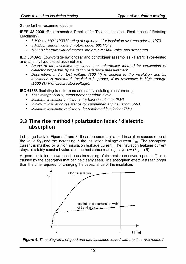
3.3 Time rise method / polarization index / dielectric absorption
Let us go back to Figures 2 and 3. It can be seen that a bad insulation causes drop of the value Riso and the increasing in the insulation leakage current IRiso. The absorption current is masked by a high insulation leakage current. The insulation leakage current stays at a fairly constant value and the resistance reading stays low (Figure 6). A good insulation shows continuous increasing of the resistance over a period. This is caused by the absorption that can be clearly seen. The absorption effect lasts far longer than the time required for charging the capacitance of the insulation.
t [min] 1 10
Rtot
Insulation contaminated with dirt and moisture
Good insulation
Figure 6: Time diagrams of good and bad insulation tested with the time-rise method
Guide to modern insulation testing Types of insulation testing
13
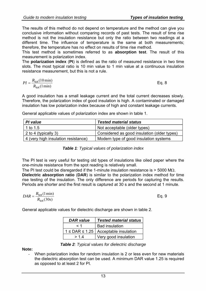
The results of this method do not depend on temperature and the method can give you conclusive information without comparing records of past tests. The result of time rise method is not the insulation resistance but only the ratio between two readings at a different time. The influence of temperature is the same at both measurements; therefore, the temperature has no effect on results of time rise method. This test method is sometimes referred to as absorption test. The result of this measurement is polarization index. The polarization index (PI) is defined as the ratio of measured resistance in two time slots. The most typical ratio is 10 min value to 1 min value at a continuous insulation resistance measurement, but this is not a rule.
min)1(min)10(
tot
totR
RPI = Eq. 8
A good insulation has a small leakage current and the total current decreases slowly. Therefore, the polarization index of good insulation is high. A contaminated or damaged insulation has low polarization index because of high and constant leakage currents. General applicable values of polarization index are shown in table 1.
PI value Tested material status 1 to 1.5 Not acceptable (older types) 2 to 4 (typically 3) Considered as good insulation (older types) 4 (very high insulation resistance) Modern type of good insulation systems
Table 1: Typical values of polarization index
The PI test is very useful for testing old types of insulations like oiled paper where the one-minute resistance from the spot reading is relatively small. The PI test could be disregarded if the 1-minute insulation resistance is > 5000 MΩ. Dielectric absorption ratio (DAR) is similar to the polarization index method for time rise testing of the insulation. The only difference are periods for capturing the results. Periods are shorter and the first result is captured at 30 s and the second at 1 minute.
)s30(min)1(
tot
totR
RDAR = Eq. 9
General applicable values for dielectric discharge are shown in table 2.
DAR value Tested material status< 1 Bad insulation
1 ≤ DAR ≤ 1.25 Acceptable insulation > 1.4 Very good insulation
Table 2: Typical values for dielectric discharge Note:
- When polarization index for random insulation is 2 or less even for new materials the dielectric absorption test can be used. A minimum DAR value 1.25 is required as opposed to at least 2 for PI.
Guide to modern insulation testing Types of insulation testing
14
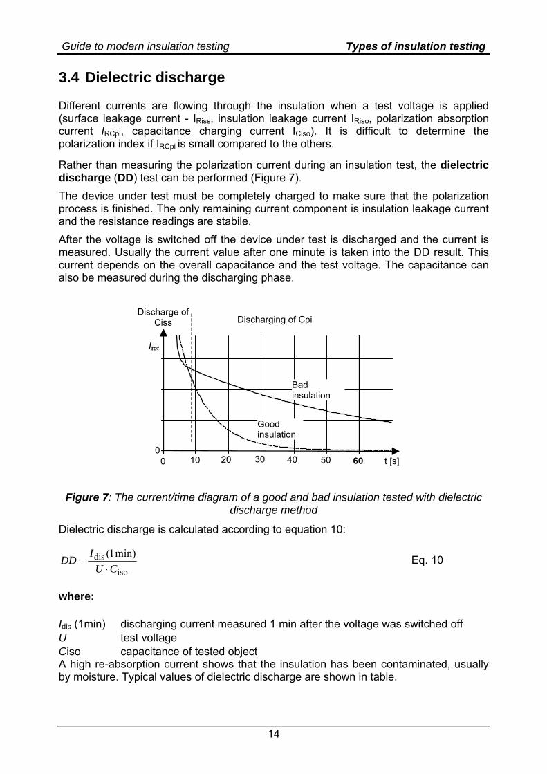
3.4 Dielectric discharge Different currents are flowing through the insulation when a test voltage is applied (surface leakage current - IRiss, insulation leakage current IRiso, polarization absorption current IRCpi, capacitance charging current ICiso). It is difficult to determine the polarization index if IRCpi is small compared to the others. Rather than measuring the polarization current during an insulation test, the dielectric discharge (DD) test can be performed (Figure 7). The device under test must be completely charged to make sure that the polarization process is finished. The only remaining current component is insulation leakage current and the resistance readings are stabile. After the voltage is switched off the device under test is discharged and the current is measured. Usually the current value after one minute is taken into the DD result. This current depends on the overall capacitance and the test voltage. The capacitance can also be measured during the discharging phase.
Discharge of Ciss
Itot
t [s] 10 20 30 40 50 6000
Bad insulation
Good insulation
Discharging of Cpi
Figure 7: The current/time diagram of a good and bad insulation tested with dielectric discharge method
Dielectric discharge is calculated according to equation 10:
iso
dis min)1(CU
IDD⋅
= Eq. 10
where: Idis (1min) discharging current measured 1 min after the voltage was switched off U test voltage Ciso capacitance of tested object A high re-absorption current shows that the insulation has been contaminated, usually by moisture. Typical values of dielectric discharge are shown in table.
Guide to modern insulation testing Types of insulation testing
15
DD value Tested material status > 4 bad 2 - 4 critical < 2 good
Table 3: Values of dielectric discharge
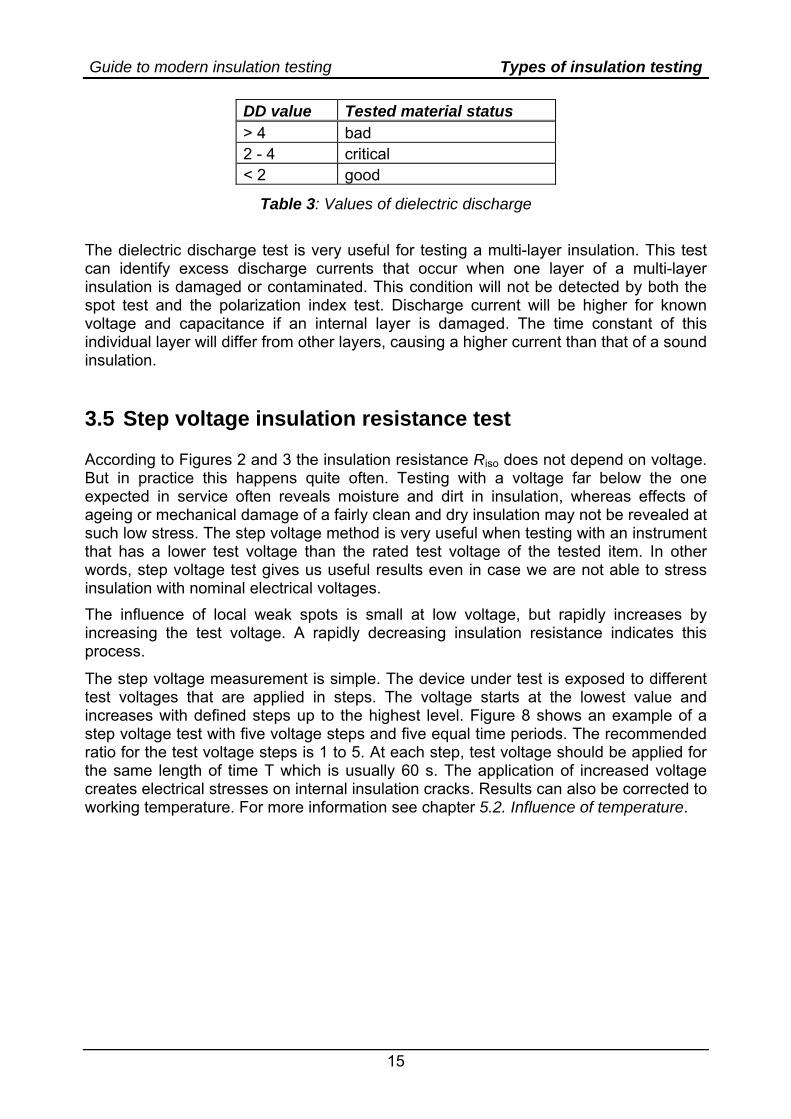
The dielectric discharge test is very useful for testing a multi-layer insulation. This test can identify excess discharge currents that occur when one layer of a multi-layer insulation is damaged or contaminated. This condition will not be detected by both the spot test and the polarization index test. Discharge current will be higher for known voltage and capacitance if an internal layer is damaged. The time constant of this individual layer will differ from other layers, causing a higher current than that of a sound insulation. 3.5 Step voltage insulation resistance test According to Figures 2 and 3 the insulation resistance Riso does not depend on voltage. But in practice this happens quite often. Testing with a voltage far below the one expected in service often reveals moisture and dirt in insulation, whereas effects of ageing or mechanical damage of a fairly clean and dry insulation may not be revealed at such low stress. The step voltage method is very useful when testing with an instrument that has a lower test voltage than the rated test voltage of the tested item. In other words, step voltage test gives us useful results even in case we are not able to stress insulation with nominal electrical voltages. The influence of local weak spots is small at low voltage, but rapidly increases by increasing the test voltage. A rapidly decreasing insulation resistance indicates this process.
The step voltage measurement is simple. The device under test is exposed to different test voltages that are applied in steps. The voltage starts at the lowest value and increases with defined steps up to the highest level. Figure 8 shows an example of a step voltage test with five voltage steps and five equal time periods. The recommended ratio for the test voltage steps is 1 to 5. At each step, test voltage should be applied for the same length of time T which is usually 60 s. The application of increased voltage creates electrical stresses on internal insulation cracks. Results can also be corrected to working temperature. For more information see chapter 5.2. Influence of temperature.
Guide to modern insulation testing Types of insulation testing
16
0
U1
U2
U3
U4
U5
U
T 2T 3T 4T 5T t
Figure 8: Typical measuring procedure for step voltage measurement.
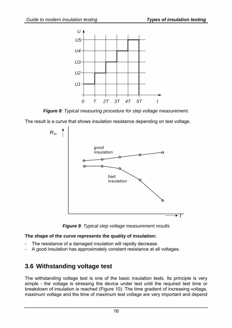
The result is a curve that shows insulation resistance depending on test voltage.
t
Rin
good insulation
bad insulation
Figure 9: Typical step voltage measurement results
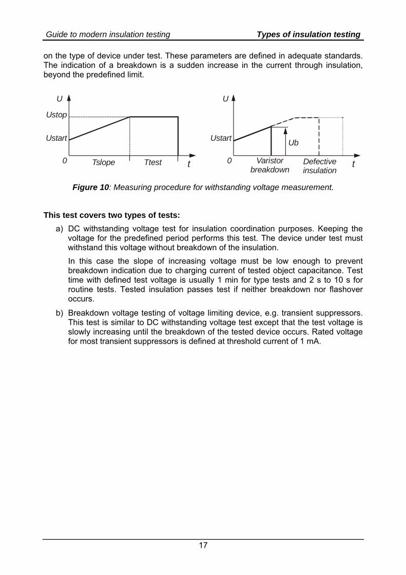
The shape of the curve represents the quality of insulation: - The resistance of a damaged insulation will rapidly decrease. - A good insulation has approximately constant resistance at all voltages. 3.6 Withstanding voltage test The withstanding voltage test is one of the basic insulation tests. Its principle is very simple - the voltage is stressing the device under test until the required test time or breakdown of insulation is reached (Figure 10). The time gradient of increasing voltage, maximum voltage and the time of maximum test voltage are very important and depend
Guide to modern insulation testing Types of insulation testing
17
on the type of device under test. These parameters are defined in adequate standards. The indication of a breakdown is a sudden increase in the current through insulation, beyond the predefined limit.
U U
Ustop
UbUstart Ustart
0 0Ttest t tTslope Varistorbreakdown
Defectiveinsulation
Figure 10: Measuring procedure for withstanding voltage measurement.
This test covers two types of tests:
a) DC withstanding voltage test for insulation coordination purposes. Keeping the voltage for the predefined period performs this test. The device under test must withstand this voltage without breakdown of the insulation. In this case the slope of increasing voltage must be low enough to prevent breakdown indication due to charging current of tested object capacitance. Test time with defined test voltage is usually 1 min for type tests and 2 s to 10 s for routine tests. Tested insulation passes test if neither breakdown nor flashover occurs.
b) Breakdown voltage testing of voltage limiting device, e.g. transient suppressors. This test is similar to DC withstanding voltage test except that the test voltage is slowly increasing until the breakdown of the tested device occurs. Rated voltage for most transient suppressors is defined at threshold current of 1 mA.
Guide to modern insulation testing Test set-up
18
4. Test set-up
4.1 Safety considerations Test set-up must be prepared carefully and correctly to prevent damage on the tested device, measuring instrument and to protect the operator. The following steps must be carried out: A) To protect device under test (DUT) and test equipment:
- Take the DUT out of service and shut it down. - Check that the DUT is disconnected from other equipment and circuits if possible. - Discharge the insulations that will be tested (METREL testers will give a warning in
case of energized DUT). - To prevent the damage of the DUT it is recommended to short accessible
connections of circuit on both sides of tested insulation. - Select correct test voltage and method. - Pay attention to grounded DUT. Some insulation testers are also connected to
ground potential (normally negative pole) that can lead to improper results. B) To protect the operator:
- Use appropriate test accessories – test leads, alligators, test tips, etc. The accessories must be intrinsically safe for required test conditions.
- Reject test equipment and accessories with noticed cracks, breaks, and/or damaged insulation.
- Fix the connection before starting the measurement. - Pay attention that the voltage source of insulation tester is current limited beyond
3.5 mA. - Tested insulation capacitance Ciso could be high enough to become hazardous live
when charged to high voltage. For more information refer to chapter 4.3. Discharging of capacitive objects after the test.
- Select threshold current limit as low as possible. - Don’t touch any part of the test system during the measurement and do not
disconnect test leads until the measurement is finished and the DUT discharged. - METREL test equipment makes automatic discharge of the test circuit at the end of
the test.
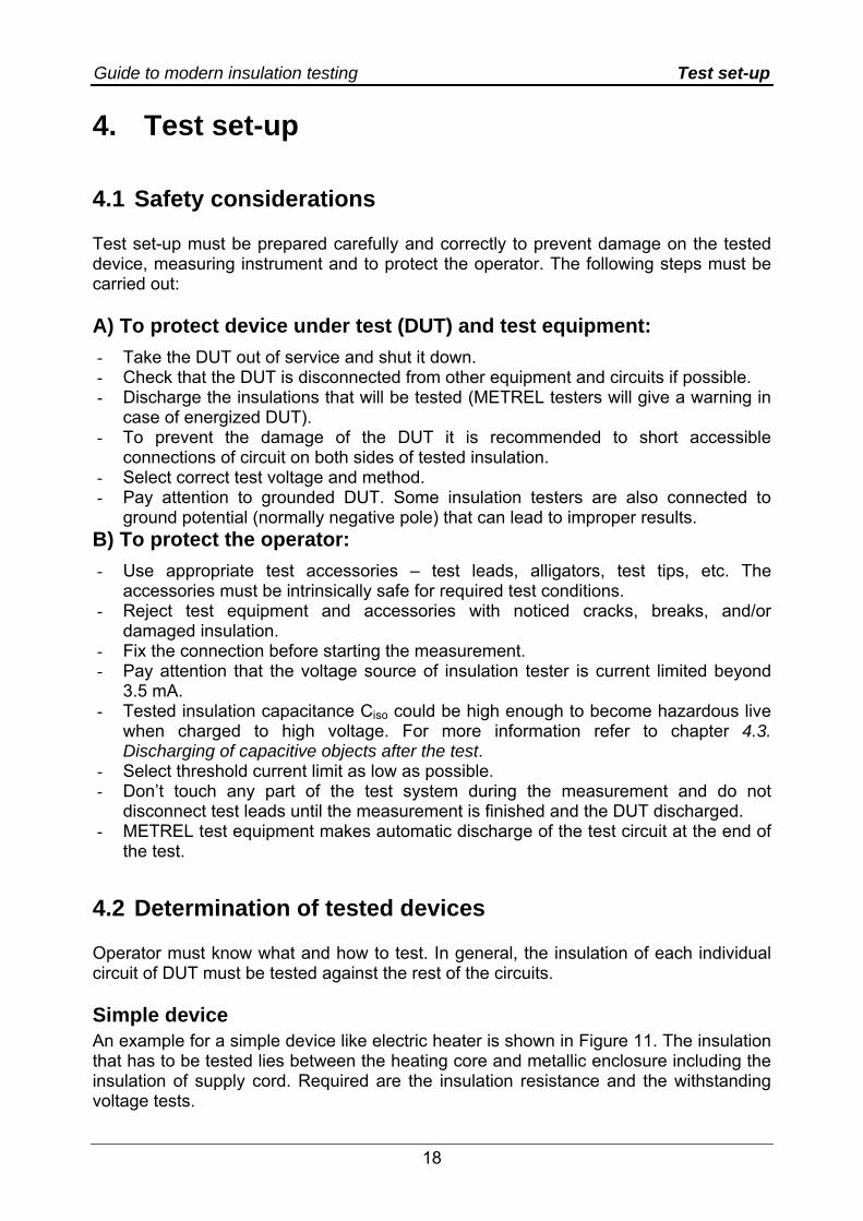
4.2 Determination of tested devices Operator must know what and how to test. In general, the insulation of each individual circuit of DUT must be tested against the rest of the circuits. Simple device An example for a simple device like electric heater is shown in Figure 11. The insulation that has to be tested lies between the heating core and metallic enclosure including the insulation of supply cord. Required are the insulation resistance and the withstanding voltage tests.
Guide to modern insulation testing Test set-up
19
PE
Metallic enclosureInsulation to test
Heater
Supply cord
Figure 11: Example of electric heater with definition of insulation to test
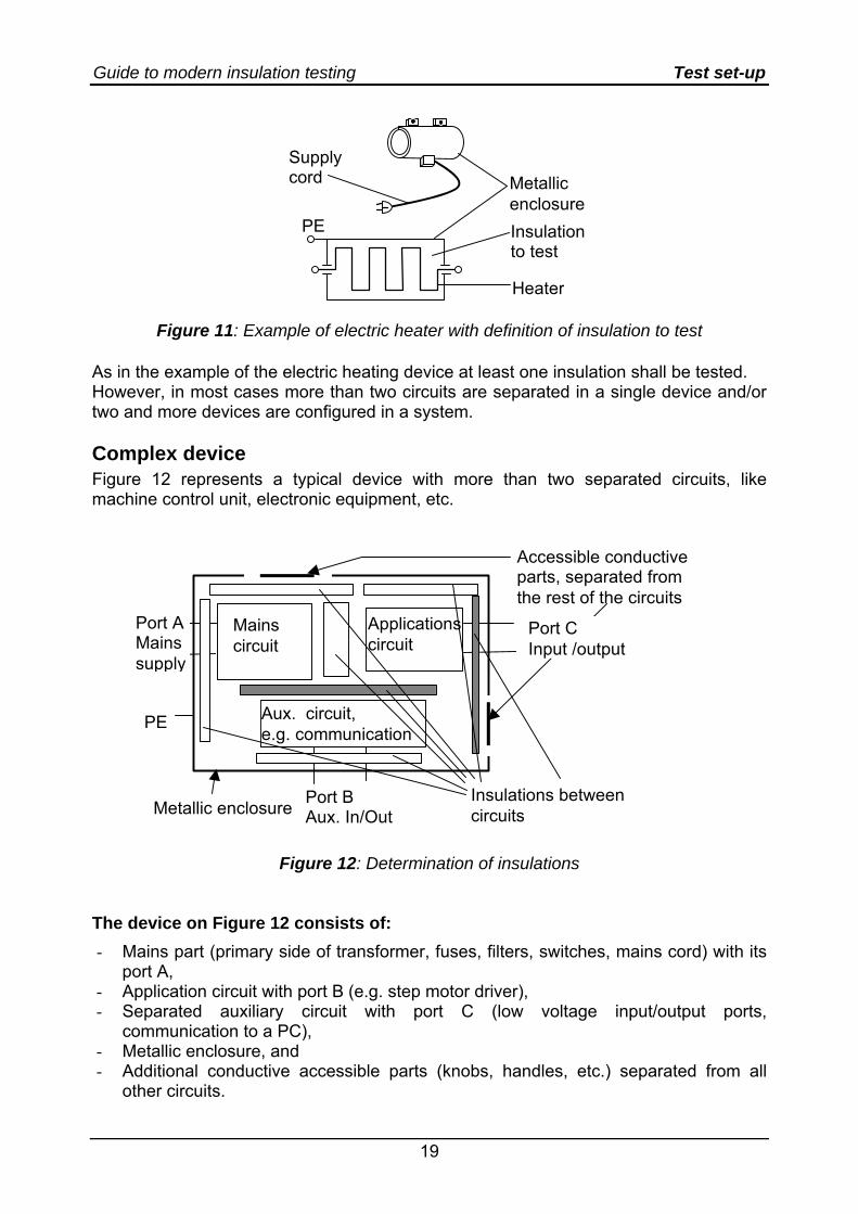
As in the example of the electric heating device at least one insulation shall be tested. However, in most cases more than two circuits are separated in a single device and/or two and more devices are configured in a system. Complex device Figure 12 represents a typical device with more than two separated circuits, like machine control unit, electronic equipment, etc.
Accessible conductive parts, separated from the rest of the circuits
Mains circuit
Applications circuit
Aux. circuit, e.g. communication
Metallic enclosure
PE
Insulations between circuits
Port A Mains su
Port C Input /output
pply
Port B Aux. In/Out
Figure 12: Determination of insulations The device on Figure 12 consists of: - Mains part (primary side of transformer, fuses, filters, switches, mains cord) with its
port A, - Application circuit with port B (e.g. step motor driver), - Separated auxiliary circuit with port C (low voltage input/output ports,
communication to a PC), - Metallic enclosure, and - Additional conductive accessible parts (knobs, handles, etc.) separated from all
other circuits.
Guide to modern insulation testing Test set-up
20
List of insulations between circuits from Figure 12:
Mains circuit to: Applications circuit to: Aux. circuit to: Metallic enclosure Metallic enclosure Metallic enclosure Accessible conductive parts separated from enclosure
Accessible conductive parts separated from enclosure
Accessible conductive parts separated from enclosure
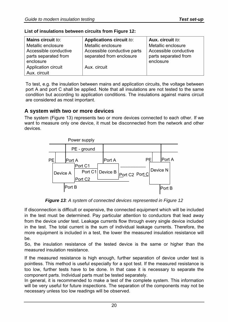
Application circuit Aux. circuit Aux. circuit To test, e.g. the insulation between mains and application circuits, the voltage between port A and port C shall be applied. Note that all insulations are not tested to the same condition but according to application conditions. The insulations against mains circuit are considered as most important. A system with two or more devices The system (Figure 13) represents two or more devices connected to each other. If we want to measure only one device, it must be disconnected from the network and other devices.
Device A Device B Device N
Power supply
PE - ground
Port A Port A Port A
Port B Port B
PE PEPort C1
Port C2 Port C2
Port C1 Port C
Figure 13: A system of connected devices represented in Figure 12
If disconnection is difficult or expensive, the connected equipment which will be included in the test must be determined. Pay particular attention to conductors that lead away from the device under test. Leakage currents flow through every single device included in the test. The total current is the sum of individual leakage currents. Therefore, the more equipment is included in a test, the lower the measured insulation resistance will be. So, the insulation resistance of the tested device is the same or higher than the measured insulation resistance.
If the measured resistance is high enough, further separation of device under test is pointless. This method is useful especially for a spot test. If the measured resistance is too low, further tests have to be done. In that case it is necessary to separate the component parts. Individual parts must be tested separately. In general, it is recommended to make a test of the complete system. This information will be very useful for future inspections. The separation of the components may not be necessary unless too low readings will be observed.
Guide to modern insulation testing Test set-up
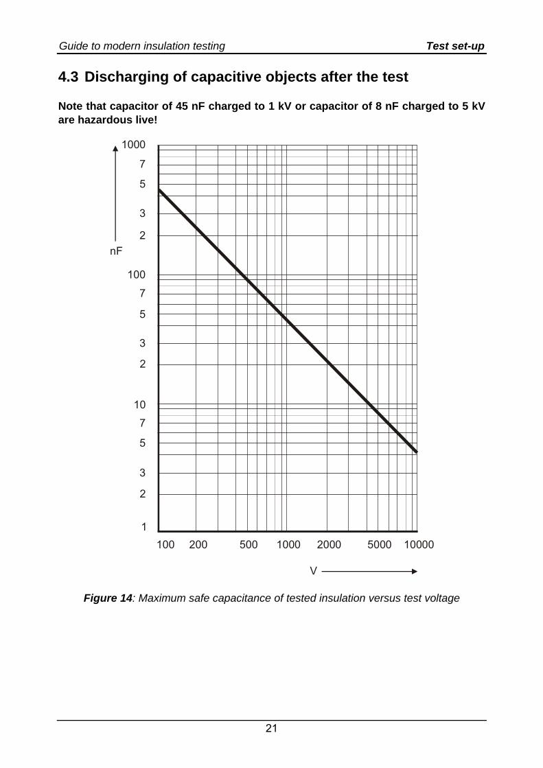
21
4.3 Discharging of capacitive objects after the test Note that capacitor of 45 nF charged to 1 kV or capacitor of 8 nF charged to 5 kV are hazardous live!
200 500 2000 5000
1000
7
5
3
2
100
7
5
3
2
10
7
5
3
2
1
V
100 1000 10000
nF
Figure 14: Maximum safe capacitance of tested insulation versus test voltage
Guide to modern insulation testing Test set-up
22
Safety limit form IEC 61010-1 for charged capacitance: - 45 μC for test voltage less than 15 kV (see Figure 14) and - 350 mJ for higher voltage.
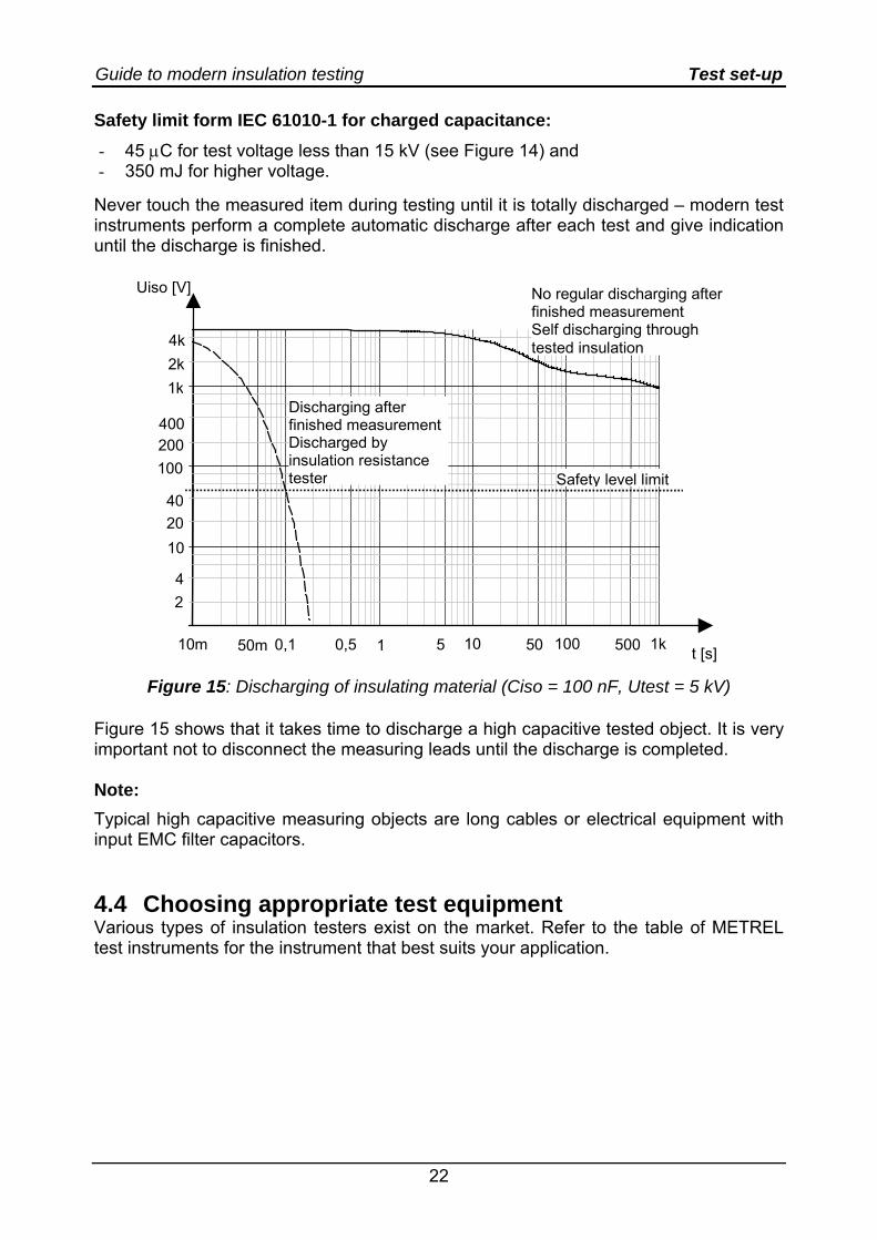
Never touch the measured item during testing until it is totally discharged – modern test instruments perform a complete automatic discharge after each test and give indication until the discharge is finished.
t [s]
Uiso [V]
10m 50m 0,1 0,5 1 5 10 50 100 500 1k
24
102040
100200400
1k2k4k
Discharging after finished measurementDischarged by insulation resistance tester
No regular discharging after finished measurement Self discharging through tested insulation
Safety level limit
Figure 15: Discharging of insulating material (Ciso = 100 nF, Utest = 5 kV)
Figure 15 shows that it takes time to discharge a high capacitive tested object. It is very important not to disconnect the measuring leads until the discharge is completed. Note: Typical high capacitive measuring objects are long cables or electrical equipment with input EMC filter capacitors. 4.4 Choosing appropriate test equipment Various types of insulation testers exist on the market. Refer to the table of METREL test instruments for the instrument that best suits your application.
Guide to modern insulation testing Typical problems during measurements
23
5. Typical problems during measurements This chapter describes different problems that often occur when performing insulation tests. Each problem is described and possible solutions are presented. Most common problems are: 1. Result too low because of surface leakages 2. Drifting because of temperature 3. Drifting because of humidity 4. Inductive and capacitive coupling of external disturbing/noise signals 5. Instability because of high capacitive loads like long cables 6. Instability and accuracy problems of very high insulation results 7. Result too low because of ground and other leakages
5.1 Result too low because of surface leakages, guarding techniques
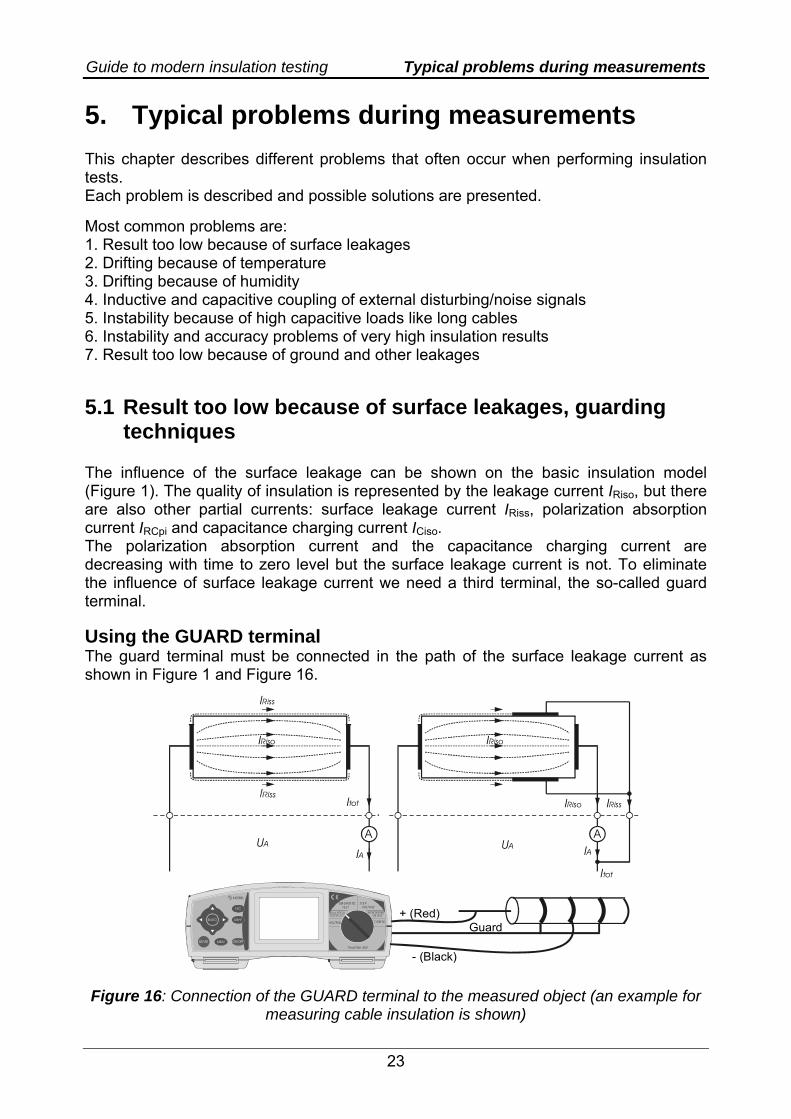
The influence of the surface leakage can be shown on the basic insulation model (Figure 1). The quality of insulation is represented by the leakage current IRiso, but there are also other partial currents: surface leakage current IRiss, polarization absorption current IRCpi and capacitance charging current ICiso. The polarization absorption current and the capacitance charging current are decreasing with time to zero level but the surface leakage current is not. To eliminate the influence of surface leakage current we need a third terminal, the so-called guard terminal. Using the GUARD terminal The guard terminal must be connected in the path of the surface leakage current as shown in Figure 1 and Figure 16.
A A
LIGHT
ESC
MEM
SELECT
TeraOhm 5kV
DIAGNOSTICTEST VOLTAGE
STEP
CONFIG
+ (Red)Guard
- (Black)
IRiss
IRiso
Itot
Itot IRiss
IRiso
UA UA
IRiso
IAIA
Figure 16: Connection of the GUARD terminal to the measured object (an example for measuring cable insulation is shown)
Guide to modern insulation testing Typical problems during measurements
24
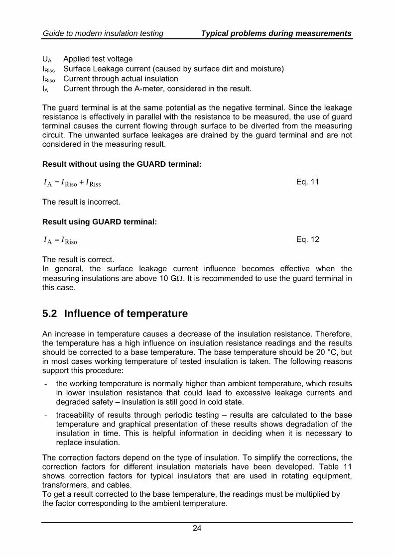
UA Applied test voltage IRiss Surface Leakage current (caused by surface dirt and moisture) IRiso Current through actual insulation IA Current through the A-meter, considered in the result. The guard terminal is at the same potential as the negative terminal. Since the leakage resistance is effectively in parallel with the resistance to be measured, the use of guard terminal causes the current flowing through surface to be diverted from the measuring circuit. The unwanted surface leakages are drained by the guard terminal and are not considered in the measuring result. Result without using the GUARD terminal:
RissRisoA III += Eq. 11
The result is incorrect. Result using GUARD terminal:
RisoA II = Eq. 12
The result is correct. In general, the surface leakage current influence becomes effective when the measuring insulations are above 10 GΩ. It is recommended to use the guard terminal in this case.
5.2 Influence of temperature An increase in temperature causes a decrease of the insulation resistance. Therefore, the temperature has a high influence on insulation resistance readings and the results should be corrected to a base temperature. The base temperature should be 20 °C, but in most cases working temperature of tested insulation is taken. The following reasons support this procedure: - the working temperature is normally higher than ambient temperature, which results
in lower insulation resistance that could lead to excessive leakage currents and degraded safety – insulation is still good in cold state.
- traceability of results through periodic testing – results are calculated to the base temperature and graphical presentation of these results shows degradation of the insulation in time. This is helpful information in deciding when it is necessary to replace insulation.
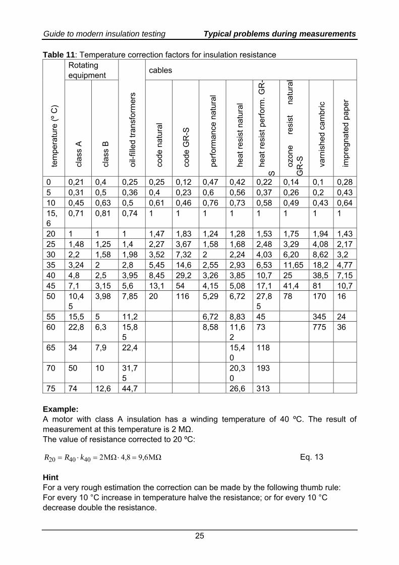
The correction factors depend on the type of insulation. To simplify the corrections, the correction factors for different insulation materials have been developed. Table 11 shows correction factors for typical insulators that are used in rotating equipment, transformers, and cables. To get a result corrected to the base temperature, the readings must be multiplied by the factor corresponding to the ambient temperature.
Guide to modern insulation testing Typical problems during measurements
25
Table 11: Temperature correction factors for insulation resistance Rotating equipment cables
te
mpe
ratu
re (º
C)
c
lass
A
c
lass
B
o
il-fil
led
trans
form
ers
c
ode
natu
ral
c
ode
GR
-S
p
erfo
rman
ce n
atur
al
h
eat r
esis
t nat
ural
he
at re
sist
per
form
. GR
-S
ozo
ne
resi
st
natu
ral
GR
-S
v
arni
shed
cam
bric
im
preg
nate
d pa
per
0 0,21 0,4 0,25 0,25 0,12 0,47 0,42 0,22 0,14 0,1 0,285 0,31 0,5 0,36 0,4 0,23 0,6 0,56 0,37 0,26 0,2 0,4310 0,45 0,63 0,5 0,61 0,46 0,76 0,73 0,58 0,49 0,43 0,6415,6
0,71 0,81 0,74 1 1 1 1 1 1 1 1
20 1 1 1 1,47 1,83 1,24 1,28 1,53 1,75 1,94 1,4325 1,48 1,25 1,4 2,27 3,67 1,58 1,68 2,48 3,29 4,08 2,1730 2,2 1,58 1,98 3,52 7,32 2 2,24 4,03 6,20 8,62 3,2 35 3,24 2 2,8 5,45 14,6 2,55 2,93 6,53 11,65 18,2 4,7740 4,8 2,5 3,95 8,45 29,2 3,26 3,85 10,7 25 38,5 7,1545 7,1 3,15 5,6 13,1 54 4,15 5,08 17,1 41,4 81 10,750 10,4
5 3,98 7,85 20 116 5,29 6,72 27,8
5 78 170 16
55 15,5 5 11,2 6,72 8,83 45 345 24 60 22,8 6,3 15,8
5 8,58 11,6
2 73 775 36
65 34 7,9 22,4 15,40
118
70 50 10 31,75
20,30
193
75 74 12,6 44,7 26,6 313 Example: A motor with class A insulation has a winding temperature of 40 ºC. The result of measurement at this temperature is 2 MΩ. The value of resistance corrected to 20 ºC:
MΩ6,98,4MΩ2404020 =⋅=⋅= kRR Eq. 13
Hint For a very rough estimation the correction can be made by the following thumb rule: For every 10 °C increase in temperature halve the resistance; or for every 10 °C decrease double the resistance.
Guide to modern insulation testing Typical problems during measurements
26
Notes - The temperature correction is especially important for spot testing. - The time-resistance and step voltage method are relatively independent of
temperature effects. - Measuring instruments are also influenced by temperature. In general the
measuring error is small compared to the change of insulation resistance for the same change of temperature. More information can be found in technical specification.
5.3 Influence of humidity The humidity of surrounding air could affect insulation resistance. But the effect of humidity also depends on ambient temperature. Very important is the dew-point temperature. This is the temperature at which the moisture vapour in air condenses as a liquid. If the device under test operates above the dew-point temperature, the results of the test will not be affected much by humidity. When the temperature decreases under the dew point the condensed moist from surrounding air does affect the results of the test. When we are testing an outdoor operating device it is recommended to make a note about weather conditions during the test. The operator must be very careful with small portable devices. If the tested device has been brought from a cold place into a warm place just before the test, the results will not be adequate. This is only one of the reasons why the device under test should not be moved just before the test and the temperature of surroundings should not change before and during the test. Without the dew-point measurement it is very hard to define if the temperature exceeds the dew-point or not. If the dew can be seen it is a clear sign that temperature is much under the dew-point, and the effects of dew will appear. However, if the temperature is just under the dew-point we can not see the dew, but the process of condensation starts on dust, in cracks, and in breaks of insulation. The only solution is the dew-point measurement that will give you a clue as to whether such invisible conditions exist, altering the test results. The condensed moist is not the only problem caused by moisture. The insulation surface can be contaminated with certain acids or salts which have property of absorbing moisture. These hygroscopic materials could unpredictably affect the test readings. Therefore, the insulation must be free of such contamination. Notes:
- It takes time to dry humidity on the tested material when it is moved to test location and that depends also on insulation resistance. Typical times to adopt the tested material to the environment of test location are:
- at least 2 hours for Riso > 10 GΩ - more than 24 hours for Riso > 100 GΩ - two days or more for Riso > 1 TΩ Air ventilation on test location can improve results especially for high humidity environment (>80 % RH).
- Measuring instruments are also influenced by humidity.
Guide to modern insulation testing Typical problems during measurements
27
As for other electronic equipment, it is strongly recommended not to use the instrument if condensation occurs due to fast temperature changes. Accuracy above 1 GΩ at very high relative humidity (beyond 95 %) can be impaired because of drifting effects in the measuring circuit. More information can be found in technical specification.
- The problem of condensed humidity in the test equipment which occurs when this is moved to test location, is similar to the one mentioned for tested insulation. Therefore, it is also required to wait 4 hours or more to stabilize micro ambient of the instrument.
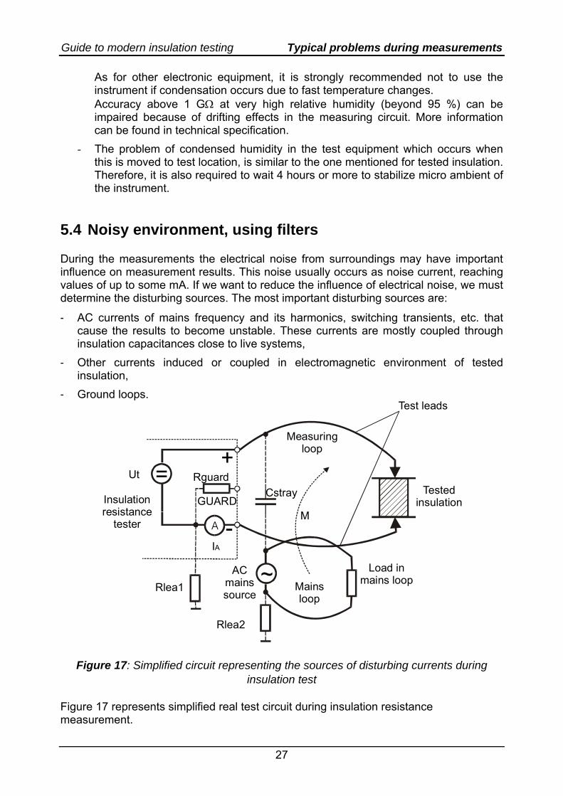
5.4 Noisy environment, using filters During the measurements the electrical noise from surroundings may have important influence on measurement results. This noise usually occurs as noise current, reaching values of up to some mA. If we want to reduce the influence of electrical noise, we must determine the disturbing sources. The most important disturbing sources are:
- AC currents of mains frequency and its harmonics, switching transients, etc. that cause the results to become unstable. These currents are mostly coupled through insulation capacitances close to live systems,
- Other currents induced or coupled in electromagnetic environment of tested insulation,
- Ground loops.
+
-GUARD
=Ut Rguard
IA
Rlea1
Rlea2
ACmains source
~
MInsulationresistance
tester
Testedinsulation
Cstray
Load in mains loopMains
loop
Measuringloop
Test leads
A
Figure 17: Simplified circuit representing the sources of disturbing currents during insulation test
Figure 17 represents simplified real test circuit during insulation resistance measurement.
Guide to modern insulation testing Typical problems during measurements
28
Elements have the following meaning:
Ut a D.C. test voltage of test equipment Rguard internal resistance of guard terminal IA measured current
Rlea1 leakage resistance of test equipment and measuring circuit to ground
Tested insulation see equivalent circuit in Figure 1 AC mains source mains supply system Load in mains loop Loading of AC mains (nonlinear loads generate harmonics) Rlea2 leakage resistance of AC mains to ground Cstray stray capacitance, it is capacitive coupling of disturbing signal M mutual inductance, generates induced current in measuring loop. Use of filters Noise sources are usually of mains frequency or they fluctuate randomly. Both can be efficiently smoothed by means of averaging and bandwidth reduction. Averaging is a method that takes more measurements and gives the result which is the mean value of them. Mean value is smoothed and has less variations than individual measurements. Bandwidth reduction gives improved rejection to noise in frequency band outside of interest. Narrower bandwidth means less noise, and improves the results similar to averaging. Averaging can smooth the remaining noise.
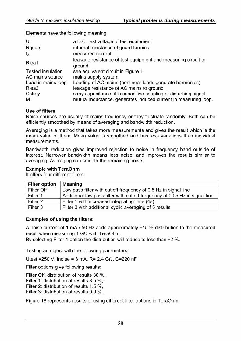
Example with TeraOhm It offers four different filters:
Filter option Meaning Filter Off Low pass filter with cut off frequency of 0.5 Hz in signal line Filter 1 Additional low pass filter with cut off frequency of 0.05 Hz in signal line Filter 2 Filter 1 with increased integrating time (4s) Filter 3 Filter 2 with additional cyclic averaging of 5 results
Examples of using the filters:
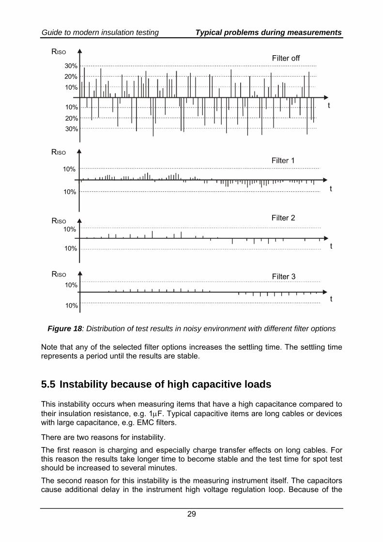
A noise current of 1 mA / 50 Hz adds approximately ±15 % distribution to the measured result when measuring 1 GΩ with TeraOhm. By selecting Filter 1 option the distribution will reduce to less than ±2 %. Testing an object with the following parameters:
Utest =250 V, Inoise = 3 mA, R= 2.4 GΩ, C=220 nF Filter options give following results: Filter Off: distribution of results 30 %, Filter 1: distribution of results 3.5 %, Filter 2: distribution of results 1.5 %, Filter 3: distribution of results 0.9 %.
Figure 18 represents results of using different filter options in TeraOhm.
Guide to modern insulation testing Typical problems during measurements
29
RISOFilter off
30%20%
10%
10%
20%30%
RISO
t
10%
10%
10%
10%
10%
10%
Filter 2
Filter 3
RISO
RISO
t
t
Figure 18: Distribution of test results in noisy environment with different filter options
Note that any of the selected filter options increases the settling time. The settling time represents a period until the results are stable. 5.5 Instability because of high capacitive loads This instability occurs when measuring items that have a high capacitance compared to their insulation resistance, e.g. 1μF. Typical capacitive items are long cables or devices with large capacitance, e.g. EMC filters. There are two reasons for instability. The first reason is charging and especially charge transfer effects on long cables. For this reason the results take longer time to become stable and the test time for spot test should be increased to several minutes. The second reason for this instability is the measuring instrument itself. The capacitors cause additional delay in the instrument high voltage regulation loop. Because of the
Guide to modern insulation testing Typical problems during measurements
30
delay, the voltage becomes slightly unstable. As can be seen from Equation 14, an additional unstable current iC will flow through the insulation capacitance Ciso (Figure 1) and be measured by the measuring circuit. Unlike the initial charging current this current flows all the time and cannot be separated from the leakage current IRiso through the insulation. If it is high compared to IRiso, the results could become very unstable.
tUCiΔ
Δ⋅= c
C Eq. 14
The instability is quite unpredictable because it depends on many factors (test voltage, Riso, Ciso, battery voltage). In general the results can be smoothed by using averaging filters. 5.6 Instability and accuracy problems of very high
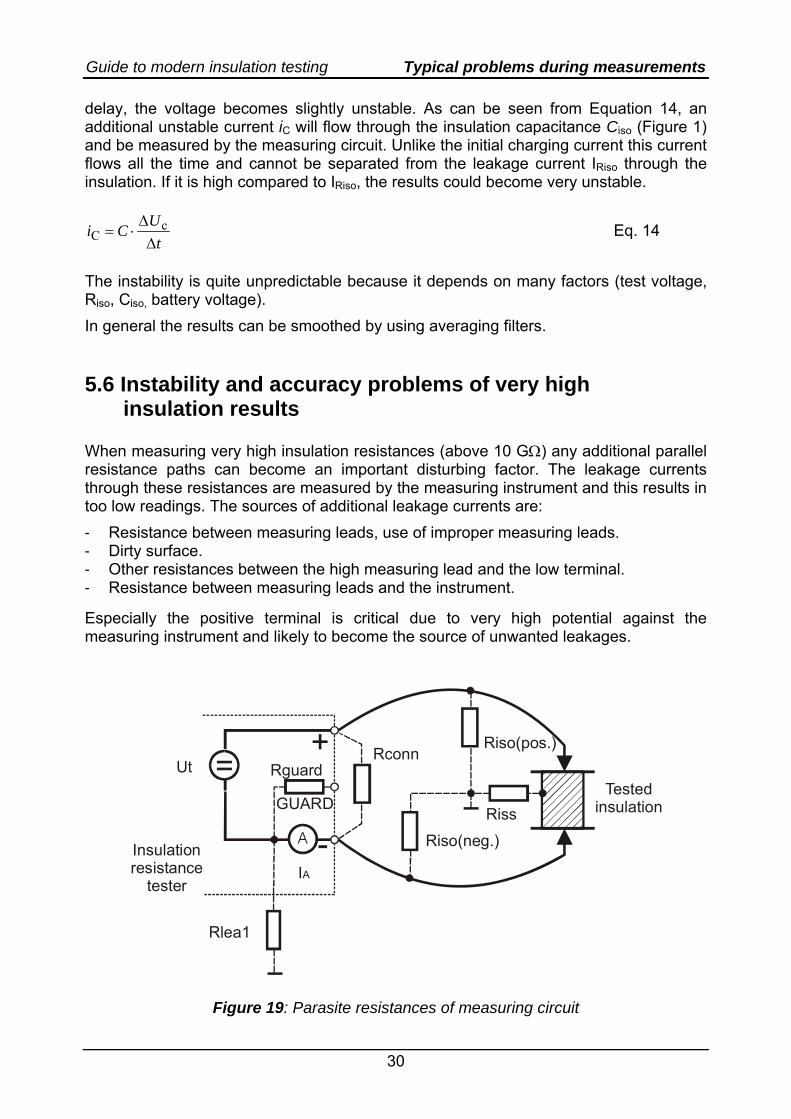
insulation results When measuring very high insulation resistances (above 10 GΩ) any additional parallel resistance paths can become an important disturbing factor. The leakage currents through these resistances are measured by the measuring instrument and this results in too low readings. The sources of additional leakage currents are: - Resistance between measuring leads, use of improper measuring leads. - Dirty surface. - Other resistances between the high measuring lead and the low terminal. - Resistance between measuring leads and the instrument. Especially the positive terminal is critical due to very high potential against the measuring instrument and likely to become the source of unwanted leakages.
+
-GUARD
=Ut Rguard
Rlea1
Insulationresistance
tester
Testedinsulation
RconnRiso(pos.)
Riso(neg.)Riss
A
IA
Figure 19: Parasite resistances of measuring circuit
Guide to modern insulation testing Typical problems during measurements
31
Leakages that influence the insulation resistance measurement:
Rlea1 leakage resistance of test equipment and measuring circuit to ground
Rconn leakage resistance on connector plate of the test instrument, caused by dirt and humidity on outer side of the instrument
Riso(pos) Riso(neg) Insulation resistance of positive and negative test leads jacket
Riss Surface resistance of tested insulation Simple measures can be taken to significantly improve the results:
o Keep the connector plate of the measuring instrument clean. o Never touch any of the measuring leads (one or both), especially during the
measurement. o The measuring leads should be leaded away from the instruments. This measure
will minimize the leakages from the leads to the instrument (a small portion of the current can avoid the guard shield and influence the results).
o Keep distance between the measuring leads. o If possible, the high terminal should not lie over the item connected to the low
terminal. o Use the guard terminal to lead the parasitic leakages away from the low terminal. o Use test leads with high quality insulation.
Insulation tester accessories contain special test leads. Standard test leads use dielectric material with lower withstanding voltage and lower insulation resistance. 5.7 Too-low result because of fixed wired and grounded
objects Sometimes the device under test is wired or in contact with other conductive items and additional current paths occur. This problem often occurs if: - Fixed installed devices that are wired with others are measured. This is especially
critical if the high terminal leads to other objects too. If disconnection is not possible the user must be able to determine the influence of other objects. Refer to Chapter 4.2 for further information about the determination of device under test.
- The measured object is grounded. There always exist different possibilities to avoid leakages into ground.
See Chapter 6 for some connection hints.
Guide to modern insulation testing Typical connections for ins. resistance testing
32
6. Typical connections for insulation resistance testing
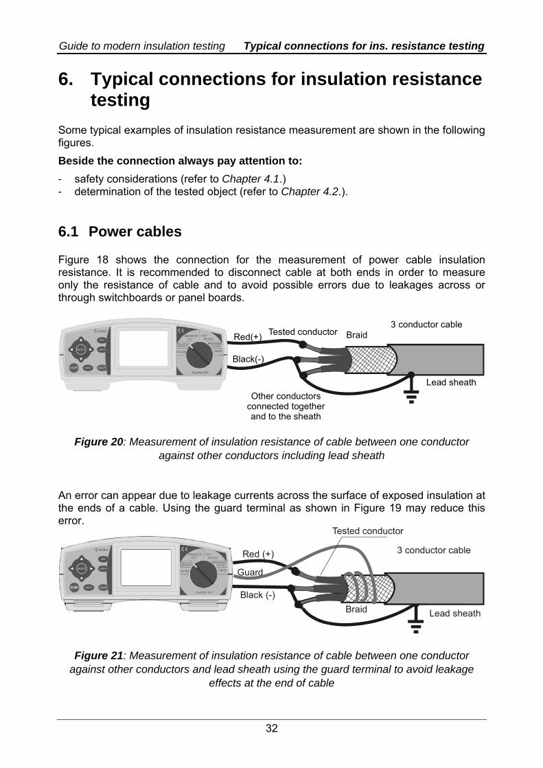
Some typical examples of insulation resistance measurement are shown in the following figures. Beside the connection always pay attention to: - safety considerations (refer to Chapter 4.1.) - determination of the tested object (refer to Chapter 4.2.). 6.1 Power cables Figure 18 shows the connection for the measurement of power cable insulation resistance. It is recommended to disconnect cable at both ends in order to measure only the resistance of cable and to avoid possible errors due to leakages across or through switchboards or panel boards.
Tested conductor3 conductor cable
Braid
Lead sheathOther conductors
connected togetherand to the sheath
LIGHT
ESC
MEM
SELECT
TeraOhm 5kV
DIAGNOSTICTEST VOLTAGE
STEP
CONFIG
Red(+)
Black(-)
Figure 20: Measurement of insulation resistance of cable between one conductor against other conductors including lead sheath
An error can appear due to leakage currents across the surface of exposed insulation at the ends of a cable. Using the guard terminal as shown in Figure 19 may reduce this error.
Tested conductor
LIGHT
ESC
MEM
SELECT
TeraOhm 5kV
DIAGNOSTICTEST VOLTAGE
STEP
CONFIG
3 conductor cable
Braid Lead sheath
Guard
Red (+)
Black (-)
Figure 21: Measurement of insulation resistance of cable between one conductor against other conductors and lead sheath using the guard terminal to avoid leakage
effects at the end of cable
Guide to modern insulation testing Typical connections for ins. resistance testing
33
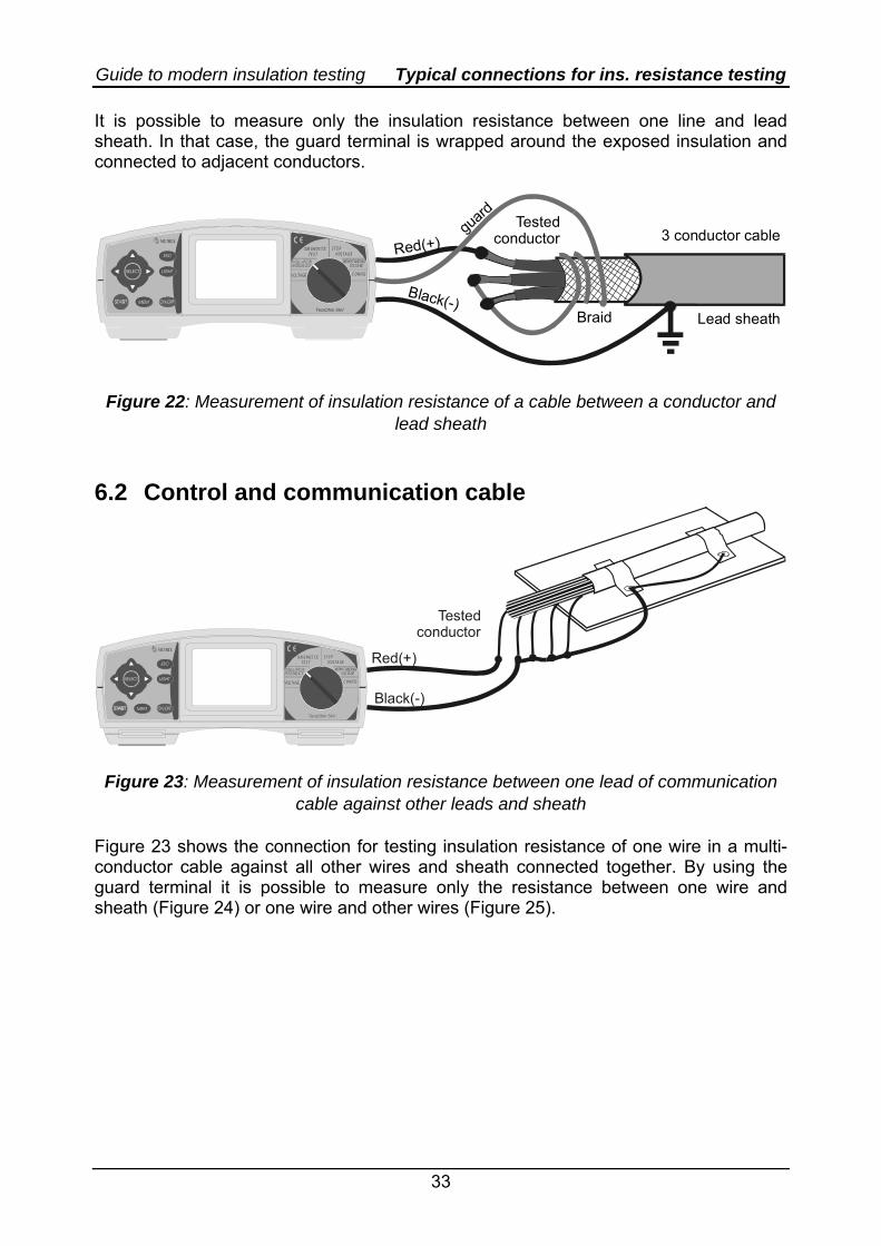
It is possible to measure only the insulation resistance between one line and lead sheath. In that case, the guard terminal is wrapped around the exposed insulation and connected to adjacent conductors.
3 conductor cable
LIGHT
ESC
MEM
SELECT
TeraOhm 5kV
DIAGNOSTICTEST VOLTAGE
STEP
CONFIG
Testedconductor
Braid Lead sheath
guard
Red(+)
Black(-)
Figure 22: Measurement of insulation resistance of a cable between a conductor and lead sheath
6.2 Control and communication cable
Testedconductor
LIGHT
ESC
MEM
SELECT
TeraOhm 5kV
DIAGNOSTICTEST VOLTAGE
STEP
CONFIG
Red(+)
Black(-)
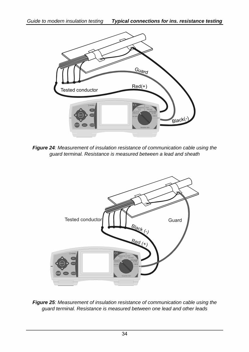
Figure 23: Measurement of insulation resistance between one lead of communication cable against other leads and sheath
Figure 23 shows the connection for testing insulation resistance of one wire in a multi-conductor cable against all other wires and sheath connected together. By using the guard terminal it is possible to measure only the resistance between one wire and sheath (Figure 24) or one wire and other wires (Figure 25).
Guide to modern insulation testing Typical connections for ins. resistance testing
34
Tested conductor
LIGHT
ESC
MEM
SELECT
TeraOhm 5kV
DIAGNOSTICTEST VOLTAGE
STEP
CONFIG
Red(+)
Guard
Black(-)
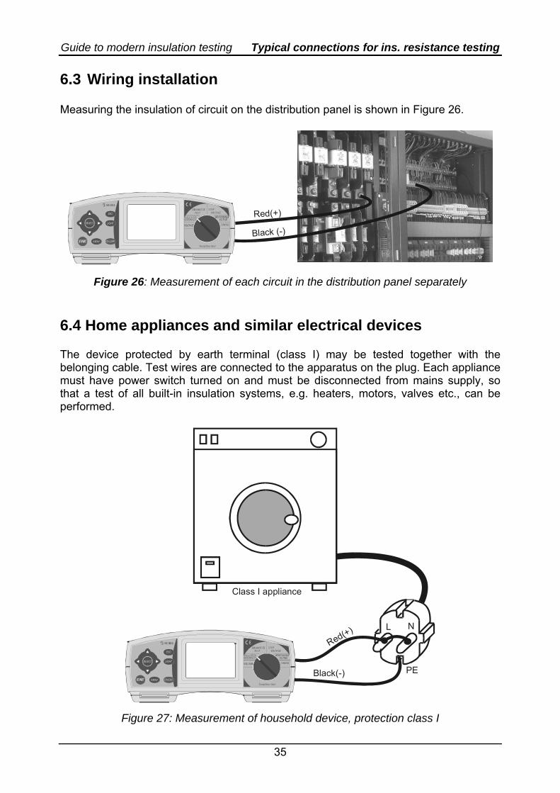
Figure 24: Measurement of insulation resistance of communication cable using the guard terminal. Resistance is measured between a lead and sheath
Tested conductor
LIGHT
ESC
MEM
SELECT
TeraOhm 5kV
DIAGNOSTICTEST VOLTAGE
STEP
CONFIG
GuardBlack (-)
Red (+)
Figure 25: Measurement of insulation resistance of communication cable using the
guard terminal. Resistance is measured between one lead and other leads
Guide to modern insulation testing Typical connections for ins. resistance testing
35
6.3 Wiring installation Measuring the insulation of circuit on the distribution panel is shown in Figure 26.
LIGHT
ESC
MEM
SELECT
TeraOhm 5kV
DIAGNOSTICTEST VOLTAGE
STEP
CONFIG
Red(+)
Black (-)
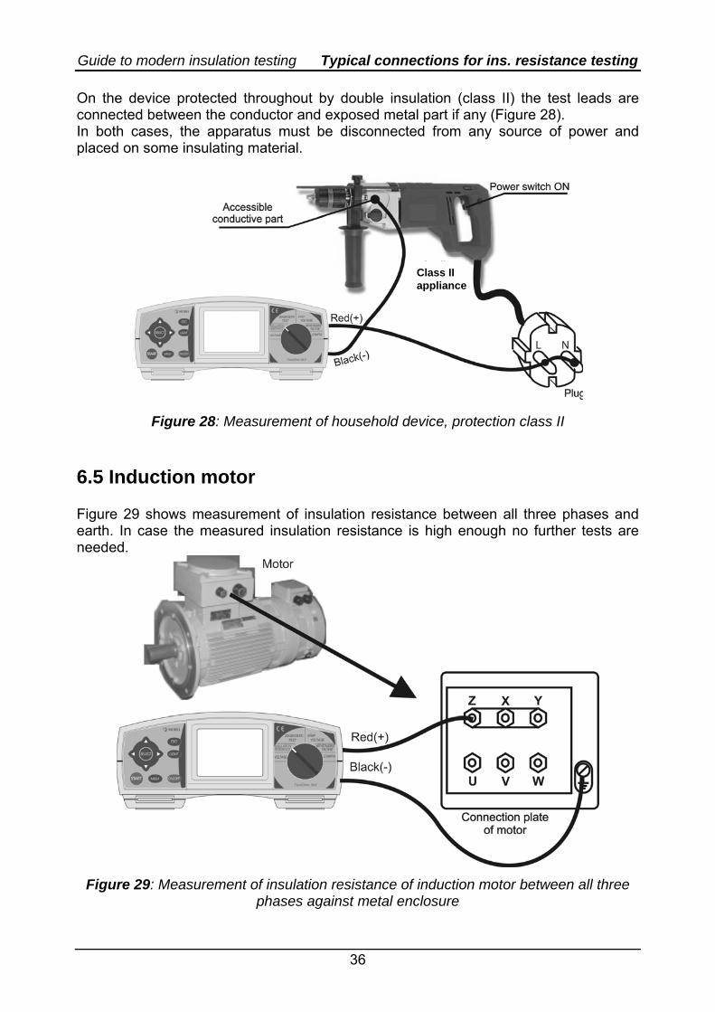
Figure 26: Measurement of each circuit in the distribution panel separately 6.4 Home appliances and similar electrical devices The device protected by earth terminal (class I) may be tested together with the belonging cable. Test wires are connected to the apparatus on the plug. Each appliance must have power switch turned on and must be disconnected from mains supply, so that a test of all built-in insulation systems, e.g. heaters, motors, valves etc., can be performed.
LIGHT
ESC
MEM
SELECT
TeraOhm 5kV
DIAGNOSTICTEST VOLTAGE
STEP
CONFIG
PE
L N
Red(+)
Black(-)
Class I appliance
Figure 27: Measurement of household device, protection class I
Guide to modern insulation testing Typical connections for ins. resistance testing
36
On the device protected throughout by double insulation (class II) the test leads are connected between the conductor and exposed metal part if any (Figure 28). In both cases, the apparatus must be disconnected from any source of power and placed on some insulating material.
Class II appliance
Figure 28: Measurement of household device, protection class II 6.5 Induction motor Figure 29 shows measurement of insulation resistance between all three phases and earth. In case the measured insulation resistance is high enough no further tests are needed.
Figure 29: Measurement of insulation resistance of induction motor between all three phases against metal enclosure
Guide to modern insulation testing Typical connections for ins. resistance testing
37
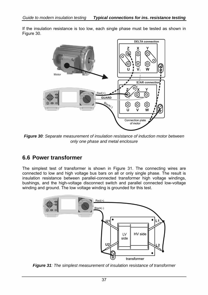
If the insulation resistance is too low, each single phase must be tested as shown in Figure 30.
Figure 30: Separate measurement of insulation resistance of induction motor between only one phase and metal enclosure
6.6 Power transformer The simplest test of transformer is shown in Figure 31. The connecting wires are connected to low and high voltage bus bars on all or only single phase. The result is insulation resistance between parallel-connected transformer high voltage windings, bushings, and the high-voltage disconnect switch and parallel connected low-voltage winding and ground. The low voltage winding is grounded for this test.
Figure 31: The simplest measurement of insulation resistance of transformer
Guide to modern insulation testing Typical connections for ins. resistance testing
38
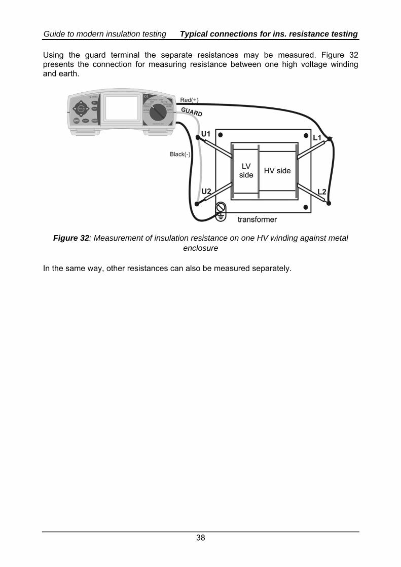
Using the guard terminal the separate resistances may be measured. Figure 32 presents the connection for measuring resistance between one high voltage winding and earth.
Figure 32: Measurement of insulation resistance on one HV winding against metal enclosure
In the same way, other resistances can also be measured separately.
Guide to modern insulation testing Interpretation of results
39
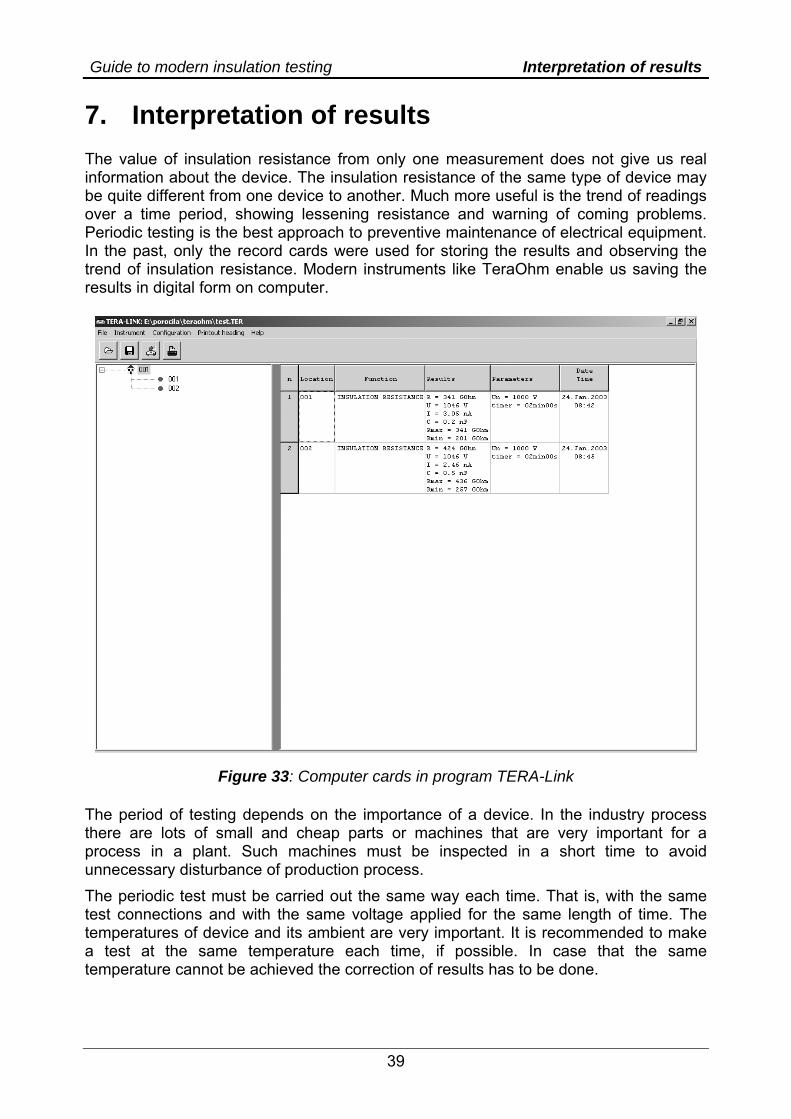
7. Interpretation of results The value of insulation resistance from only one measurement does not give us real information about the device. The insulation resistance of the same type of device may be quite different from one device to another. Much more useful is the trend of readings over a time period, showing lessening resistance and warning of coming problems. Periodic testing is the best approach to preventive maintenance of electrical equipment. In the past, only the record cards were used for storing the results and observing the trend of insulation resistance. Modern instruments like TeraOhm enable us saving the results in digital form on computer.
Figure 33: Computer cards in program TERA-Link The period of testing depends on the importance of a device. In the industry process there are lots of small and cheap parts or machines that are very important for a process in a plant. Such machines must be inspected in a short time to avoid unnecessary disturbance of production process. The periodic test must be carried out the same way each time. That is, with the same test connections and with the same voltage applied for the same length of time. The temperatures of device and its ambient are very important. It is recommended to make a test at the same temperature each time, if possible. In case that the same temperature cannot be achieved the correction of results has to be done.
Guide to modern insulation testing Interpretation of results
40
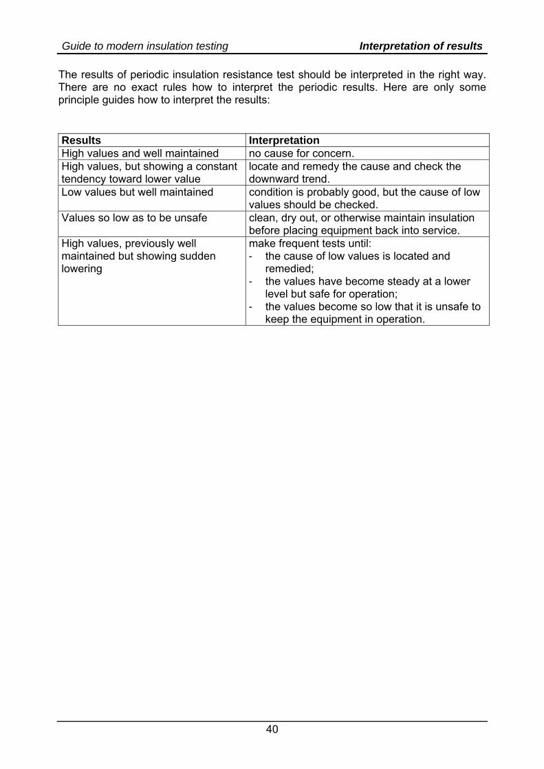
The results of periodic insulation resistance test should be interpreted in the right way. There are no exact rules how to interpret the periodic results. Here are only some principle guides how to interpret the results: Results Interpretation High values and well maintained no cause for concern. High values, but showing a constant tendency toward lower value
locate and remedy the cause and check the downward trend.
Low values but well maintained condition is probably good, but the cause of low values should be checked.
Values so low as to be unsafe clean, dry out, or otherwise maintain insulation before placing equipment back into service.
High values, previously well maintained but showing sudden lowering
make frequent tests until: - the cause of low values is located and
remedied; - the values have become steady at a lower
level but safe for operation; - the values become so low that it is unsafe to
keep the equipment in operation.
Guide to modern insulation testing Standards
41
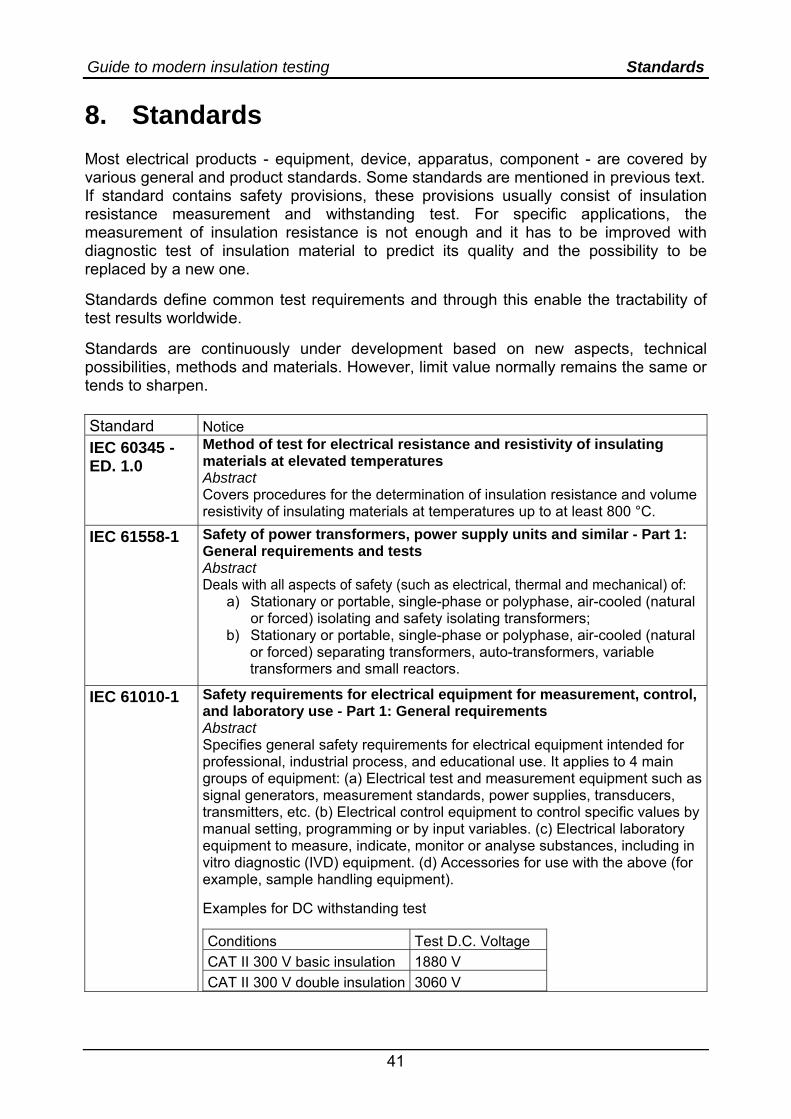
8. Standards Most electrical products - equipment, device, apparatus, component - are covered by various general and product standards. Some standards are mentioned in previous text. If standard contains safety provisions, these provisions usually consist of insulation resistance measurement and withstanding test. For specific applications, the measurement of insulation resistance is not enough and it has to be improved with diagnostic test of insulation material to predict its quality and the possibility to be replaced by a new one. Standards define common test requirements and through this enable the tractability of test results worldwide. Standards are continuously under development based on new aspects, technical possibilities, methods and materials. However, limit value normally remains the same or tends to sharpen. Standard Notice IEC 60345 - ED. 1.0
Method of test for electrical resistance and resistivity of insulating materials at elevated temperatures Abstract Covers procedures for the determination of insulation resistance and volume resistivity of insulating materials at temperatures up to at least 800 °C.
IEC 61558-1
Safety of power transformers, power supply units and similar - Part 1: General requirements and tests Abstract Deals with all aspects of safety (such as electrical, thermal and mechanical) of:
a) Stationary or portable, single-phase or polyphase, air-cooled (natural or forced) isolating and safety isolating transformers;
b) Stationary or portable, single-phase or polyphase, air-cooled (natural or forced) separating transformers, auto-transformers, variable transformers and small reactors.
IEC 61010-1 Safety requirements for electrical equipment for measurement, control, and laboratory use - Part 1: General requirements Abstract Specifies general safety requirements for electrical equipment intended for professional, industrial process, and educational use. It applies to 4 main groups of equipment: (a) Electrical test and measurement equipment such as signal generators, measurement standards, power supplies, transducers, transmitters, etc. (b) Electrical control equipment to control specific values by manual setting, programming or by input variables. (c) Electrical laboratory equipment to measure, indicate, monitor or analyse substances, including in vitro diagnostic (IVD) equipment. (d) Accessories for use with the above (for example, sample handling equipment). Examples for DC withstanding test
Conditions Test D.C. Voltage CAT II 300 V basic insulation 1880 V CAT II 300 V double insulation 3060 V
Guide to modern insulation testing Standards
42
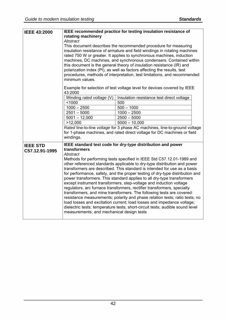
IEEE 43:2000 IEEE recommended practice for testing insulation resistance of rotating machinery Abstract This document describes the recommended procedure for measuring insulation resistance of armature and field windings in rotating machines rated 750 W or greater. It applies to synchronous machines, induction machines, DC machines, and synchronous condensers. Contained within this document is the general theory of insulation resistance (IR) and polarization index (PI), as well as factors affecting the results, test procedures, methods of interpretation, test limitations, and recommended minimum values. Example for selection of test voltage level for devices covered by IEEE 43:2000 Winding rated voltage (V) Insulation resistance test direct voltage<1000 500 1000 – 2500 500 – 1000 2501 – 5000 1000 – 2500 5001 – 12,000 2500 – 5000 >12,000 5000 – 10,000
Rated line-to-line voltage for 3 phase AC machines, line-to-ground voltage for 1-phase machines, and rated direct voltage for DC machines or field windings.
IEEE STD C57.12.91-1995
IEEE standard test code for dry-type distribution and power transformers Abstract Methods for performing tests specified in IEEE Std C57.12.01-1989 and other referenced standards applicable to dry-type distribution and power transformers are described. This standard is intended for use as a basis for performance, safety, and the proper testing of dry-type distribution and power transformers. This standard applies to all dry-type transformers except instrument transformers, step-voltage and induction voltage regulators, arc furnace transformers, rectifier transformers, specialty transformers, and mine transformers. The following tests are covered: resistance measurements; polarity and phase relation tests; ratio tests; no load losses and excitation current; load losses and impedance voltage; dielectric tests; temperature tests; short-circuit tests; audible sound level measurements; and mechanical design tests
Guide to modern insulation testing Glossary
43
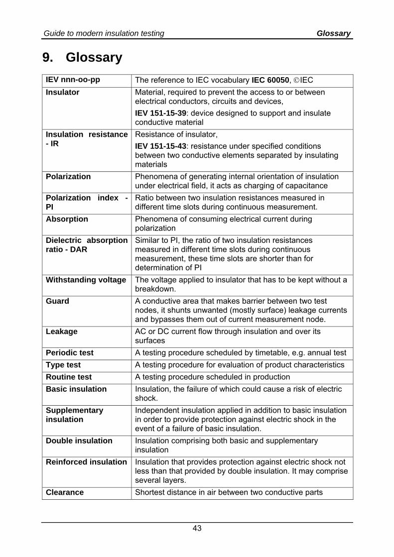
9. Glossary IEV nnn-oo-pp The reference to IEC vocabulary IEC 60050, ©IEC Insulator Material, required to prevent the access to or between
electrical conductors, circuits and devices, IEV 151-15-39: device designed to support and insulate conductive material
Insulation resistance - IR
Resistance of insulator, IEV 151-15-43: resistance under specified conditions between two conductive elements separated by insulating materials
Polarization Phenomena of generating internal orientation of insulation under electrical field, it acts as charging of capacitance
Polarization index - PI
Ratio between two insulation resistances measured in different time slots during continuous measurement.
Absorption Phenomena of consuming electrical current during polarization
Dielectric absorption ratio - DAR
Similar to PI, the ratio of two insulation resistances measured in different time slots during continuous measurement, these time slots are shorter than for determination of PI
Withstanding voltage The voltage applied to insulator that has to be kept without a breakdown.
Guard A conductive area that makes barrier between two test nodes, it shunts unwanted (mostly surface) leakage currents and bypasses them out of current measurement node.
Leakage AC or DC current flow through insulation and over its surfaces
Periodic test A testing procedure scheduled by timetable, e.g. annual test Type test A testing procedure for evaluation of product characteristics Routine test A testing procedure scheduled in production Basic insulation Insulation, the failure of which could cause a risk of electric
shock. Supplementary insulation
Independent insulation applied in addition to basic insulation in order to provide protection against electric shock in the event of a failure of basic insulation.
Double insulation Insulation comprising both basic and supplementary insulation
Reinforced insulation Insulation that provides protection against electric shock not less than that provided by double insulation. It may comprise several layers.
Clearance Shortest distance in air between two conductive parts
Guide to modern insulation testing Glossary
44
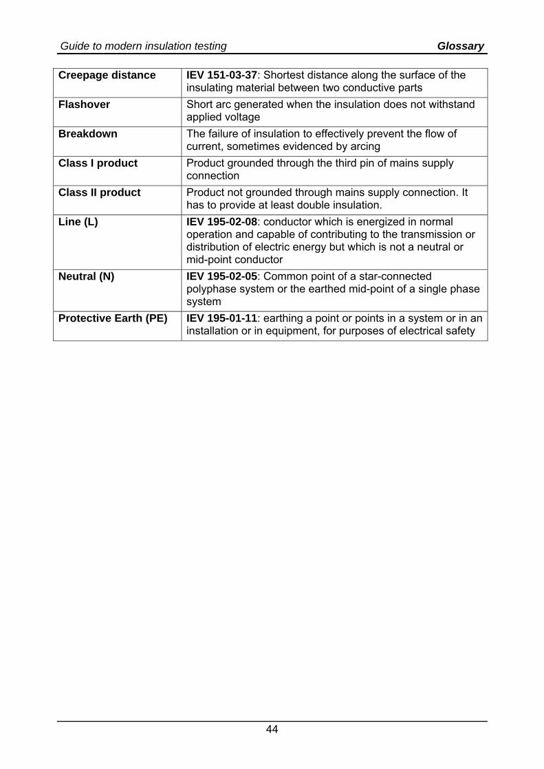
Creepage distance IEV 151-03-37: Shortest distance along the surface of the insulating material between two conductive parts
Flashover Short arc generated when the insulation does not withstand applied voltage
Breakdown The failure of insulation to effectively prevent the flow of current, sometimes evidenced by arcing
Class I product Product grounded through the third pin of mains supply connection
Class II product Product not grounded through mains supply connection. It has to provide at least double insulation.
Line (L) IEV 195-02-08: conductor which is energized in normal operation and capable of contributing to the transmission or distribution of electric energy but which is not a neutral or mid-point conductor
Neutral (N) IEV 195-02-05: Common point of a star-connected polyphase system or the earthed mid-point of a single phase system
Protective Earth (PE) IEV 195-01-11: earthing a point or points in a system or in an installation or in equipment, for purposes of electrical safety
Guide to modern insulation testing Recommended measurement instruments
45
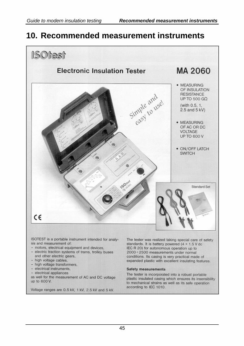
10. Recommended measurement instruments
Guide to modern insulation testing Recommended measurement instruments
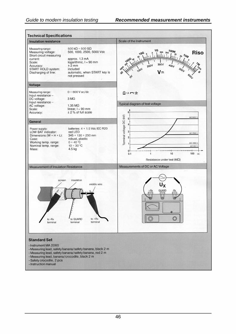
46
Guide to modern insulation testing Recommended measurement instruments
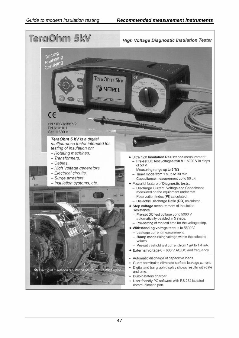
47
Guide to modern insulation testing Recommended measurement instruments
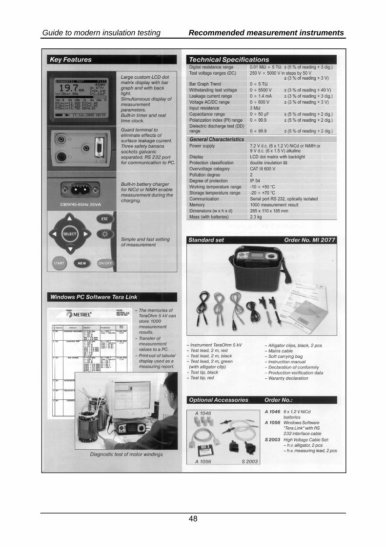
48
Top Related