


Languages
Pages
Legal


I N T E R N A T I O N A L
GENERAL PRODUCT CATALOGUE
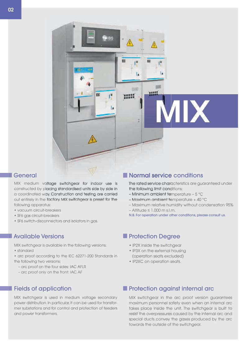
MIX medium voltage switchgear for indoor use is constructed by placing standardised units side by side in a coordinated way. Construction and testing are carried out entirely in the factory. MIX switchgear is preset for the following apparatus:• vacuum circuit-breakers• SF6 gas circuit-breakers• SF6 switch-disconnectors and isolators in gas.
MIX switchgear is available in the following versions:• standard• arc proof according to the IEC 62271-200 Standards in the following two versions: – arc proof on the four sides: IAC AFLR – arc proof only on the front: IAC AF
MIX switchgear is used in medium voltage secondary power distribution. In particular, it can be used for transfor-mer substations and for control and protection of feeders and power transformers.
N.B. For operation under other conditions, please consult us.
The rated service characteristics are guaranteed under the following limit conditions:– Minimum ambient temperature – 5 °C– Maximum ambient temperature + 40 °C– Maximum relative humidity without condensation 95%– Altitude ≤ 1.000 m s.l.m.
• IP2X inside the switchgear• IP3X on the external housing (operation seats excluded)• IP2XC on operation seats.
MIX switchgear in the arc proof version guarantees maximum personnel safety even when an internal arc takes place inside the unit. The switchgear is built to resist the overpressures caused by the internal arc and special ducts convey the gases produced by the arc towards the outside of the switchgear.
General
02
Available Versions
Fields of application
Normal service conditions
Protection Degree
Protection against internal arc
medium voltage switchgear for indoor use is constructed by placing standardised units side by side in a coordinated way. Construction and testing are carried out entirely in the factory. MIX switchgear is preset for the
The rated service characteristics are guaranteed under the following limit conditions:– Minimum ambient temperature – 5 °C– Maximum ambient temperature + 40 °C
Normal service conditions
MIX
03
* Dimensioni ridotte / Reduced dimensions
Rated power-frequency withstand voltage 50Hz 1Min to earth and between phases (kV r.m.s.) 50kV 7050
Rated voltage kV 12/24R* 24 36
60kV 60 80Rated power-frequency withstand voltage 50Hz 1Min across the isolating distance (kV r.m.s.)
125kV 125 170Rated lightning inpulse withstand voltage to earth and between phases (peak value)
145kV 145 195Rated lightning inpulse withstand voltage across the isolating distance (peak value)
400
630
1250
A400
630
1250
400
630
1250
Rated current
16-1s
20-1s
25-1s
kA
16-1s
20-1s
25-1s
12,5-1s
16-1s
20-1s
Short-time withstand current
12,5
16kA
12,5
16
12,5
16Withstand internal arc
IP2X
IP3X
IP2X
IP3X
IP2x
IP3XProtection degree indoor / outdoor
Electrical characteristics
Compliance with StandardsMIX switchgear complies with the following Standards:• IEC 62271-200• EN 62271-200.In particular, with reference to the new classifications introduced by the standards, MIX switchgear is defined as follows: – classification of service continuity: LSC2A – classification of the partitions: PM (Partitions Metallic) and PI (Partitions insulated) – classification of arc proofing (on request): IAC AFLR (or simplified version IAC AF).
Normal service conditions
The rated service characteristics are guaranteed under the following limit conditions:– Minimum ambient temperature – 5 °C– Maximum ambient temperature + 40 °C– Maximum relative humidity without condensation 95%– Altitude ≤ 1.000 m s.l.m.
N.B. For operation under other conditions, please consult us.
04
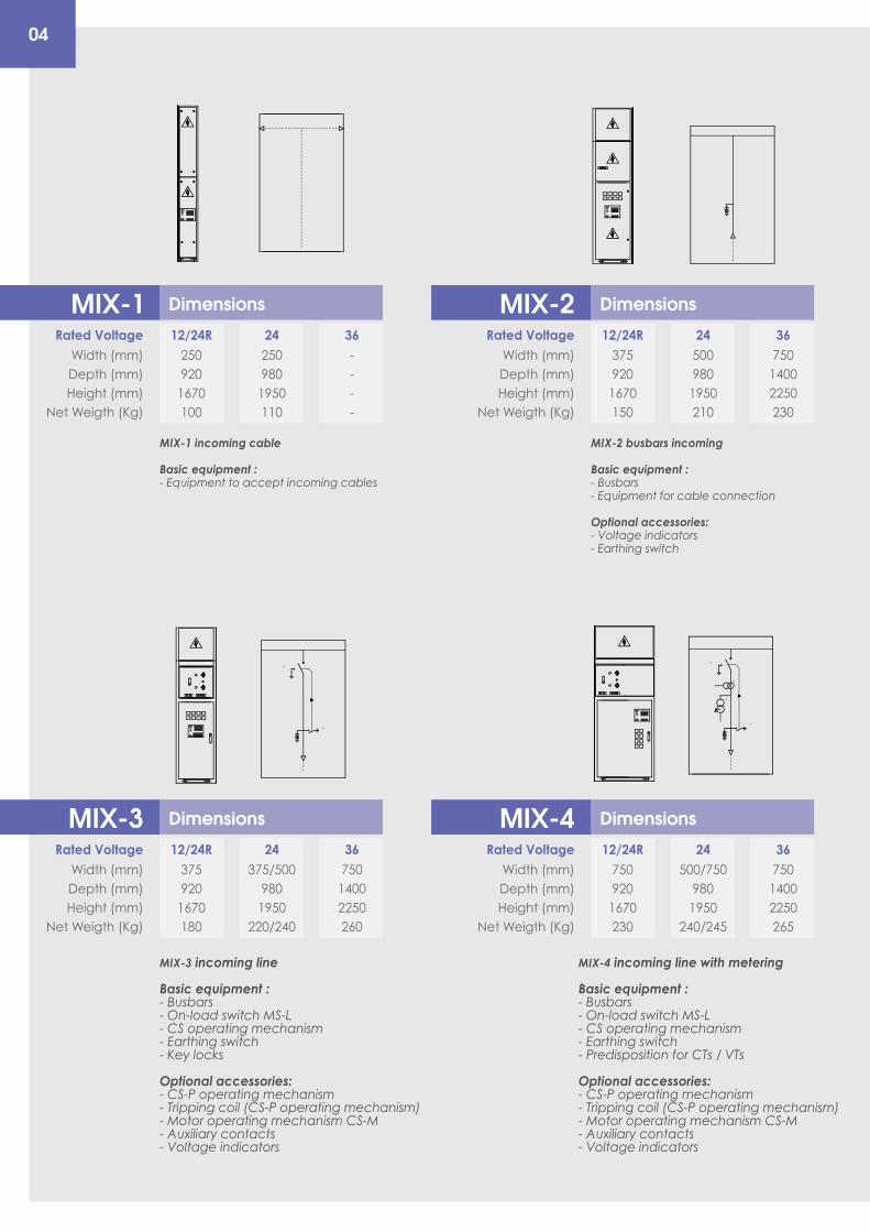
MIX-2 busbars incoming
Basic equipment :- Busbars- Equipment for cable connection
Optional accessories:- Voltage indicators- Earthing switch
MIX-1 incoming cable
Basic equipment :- Equipment to accept incoming cables
Dimensions
Width (mm)Depth (mm)Height (mm)
Net Weigth (Kg)
2509201670100
2509801950110
----
12/24RRated Voltage 24 36
MIX-1 Dimensions
Width (mm)Depth (mm)Height (mm)
Net Weigth (Kg)
3759201670150
5009801950210
75014002250230
12/24RRated Voltage 24 36
MIX-2
Dimensions
Width (mm)Depth (mm)Height (mm)
Net Weigth (Kg)
3759201670180
375/5009801950
220/240
75014002250260
12/24RRated Voltage 24 36
MIX-3 Dimensions
Width (mm)Depth (mm)Height (mm)
Net Weigth (Kg)
7509201670230
500/7509801950
240/245
75014002250265
12/24RRated Voltage 24 36
MIX-4
MIX-4 incoming line with metering
Basic equipment :- Busbars- On-load switch MS-L- CS operating mechanism- Earthing switch- Predisposition for CTs / VTs
Optional accessories:- CS-P operating mechanism- Tripping coil (CS-P operating mechanism)- Motor operating mechanism CS-M- Auxiliary contacts- Voltage indicators
MIX-3 incoming line
Basic equipment :- Busbars- On-load switch MS-L- CS operating mechanism- Earthing switch- Key locks
Optional accessories:- CS-P operating mechanism- Tripping coil (CS-P operating mechanism)- Motor operating mechanism CS-M- Auxiliary contacts- Voltage indicators
3
3
-ST
-SL
SEZ.
LINE
A
A
SEZ.
TERR
A
C
3
-ST
-SL
-TA
TV
SEZ.
LINE
A
A
SEZ.
TERR
A
C
05
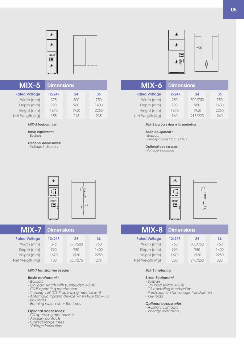
MIX-6 busbars riser with metering
Basic equipment :- Busbars- Predisposition for CTs / VTs
Optional accessories:-Voltage indicators
MIX-5 busbars riser
Basic equipment :- Busbars
Optional accessories:- Voltage indicators
Dimensions
Width (mm)Depth (mm)Height (mm)
Net Weigth (Kg)
2509201670160
500/7509801950
215/220
75014002250240
12/24RRated Voltage 24 36
MIX-6
Dimensions
Width (mm)Depth (mm)Height (mm)
Net Weigth (Kg)
7509201670230
500/7509801950
240/250
75014002250320
12/24RRated Voltage 24 36
MIX-8
MIX-8 metering
Basic Equipment- Busbars- On load switch MS-TR- CS operating mechanism- Predisposition for voltage transformers- Key locks
Optional accessories:- Auxiliary contacts- Voltage indicators
MIX-7 transformer feeder
Basic equipment :- Busbars- On-load switch with fuseholders MS-TR- CS-P operating mechanism- Tripping coil (CS-P operating mechanism)- Automatic tripping device when fuse blow-up- Key locks- Earthing switch after the fuses
Optional accessories:- CS operating mechanism- Auxiliary contacts- Correct range fuses- Voltage indicators
Dimensions
Width (mm)Depth (mm)Height (mm)
Net Weigth (Kg)
3759201670155
5009801950215
75014002250235
12/24RRated Voltage 24 36
MIX-5
Dimensions
Width (mm)Depth (mm)Height (mm)
Net Weigth (Kg)
3759201670180
375/5009801950
255/275
75014002250295
12/24RRated Voltage 24 36
MIX-7
-TA
TV
3
-ST
-SL
SEZ.
LINE
A
A
SEZ.
TERR
A
C
3
TV
-SL
-ST
SEZ.
LINE
A
A
SEZ.
TERR
A
C
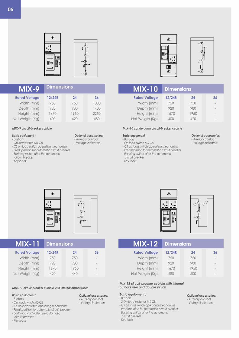
06
MIX-10 upside down circuit-breaker cubicle
Basic equipment :- Busbars- On load switch MS-CB- CS on load switch operating mechanism- Predisposition for automatic circuit-breaker- Earthing switch after the automatic circuit breaker- Key locks
MIX-9 circuit-breaker cubicle
Basic equipment :- Busbars- On load switch MS-CB- CS on load switch operating mechanism- Predisposition for automatic circuit-breaker- Earthing switch after the automatic circuit breaker- Key locks
Optional accessories:- Auxiliary contact- Voltage indicators
Optional accessories:- Auxiliary contact- Voltage indicators
MIX-12 circuit-breaker cubicle with internalbusbars riser and double switch
Basic equipment :- Busbars- 2 On load switches MS-CB- CS on load switch operating mechanism- Predisposition for automatic circuit-breaker- Earthing switch after the automatic circuit breaker- Key locks
MIX-11 circuit-breaker cubicle with internal busbars riser
Basic equipment :- Busbars- On load switch MS-CB- CS on load switch operating mechanism- Predisposition for automatic circuit-breaker- Earthing switch after the automatic circuit breaker- Key locks
Optional accessories:- Auxiliary contact- Voltage indicators
Optional accessories:- Auxiliary contact- Voltage indicators
Dimensions
Width (mm)Depth (mm)Height (mm)
Net Weigth (Kg)
7509201670400
7509801950420
100014002250480
12/24RRated Voltage 24 36
MIX-9 Dimensions
Width (mm)Depth (mm)Height (mm)
Net Weigth (Kg)
7509201670400
7509801950420
----
12/24RRated Voltage 24 36
MIX-10
Dimensions
Width (mm)Depth (mm)Height (mm)
Net Weigth (Kg)
7509201670420
7509801950440
----
12/24RRated Voltage 24 36
MIX-11 Dimensions
Width (mm)Depth (mm)Height (mm)
Net Weigth (Kg)
7509201670480
7509801950500
----
12/24RRated Voltage 24 36
MIX-12
-SL
3
OI-ST
-TA
-TA
SEZ.
LINE
A
A
SEZ.
TERR
A
C
-SL
3
OI-ST
-TA
SEZ.
LINE
A
A
SEZ.
TERR
A
C
OI
3
-ST
-SL
-TA
-TA
SEZ.
LINE
A
A
SEZ.
TERR
A
C
-SL
3
OI
-TA
-SL
-ST -ST
SEZ.
LINE
A
A
SEZ.
TERR
A
C
SEZ.
LINE
A
A
SEZ.
TERR
A
C
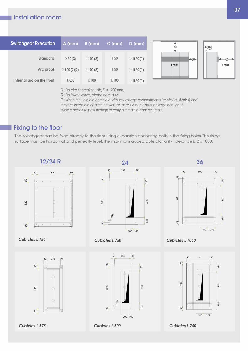
Installation room07
Switchgear Execution A (mm) B (mm) C (mm) D (mm)
Standard ≥ 50 (3) ≥ 100 (3) ≥ 50 ≥ 1550 (1)
Arc proof ≥ 600 (2)(3) ≥ 100 (3) ≥ 50 ≥ 1550 (1)
≥ 600 ≥ 100 ≥ 100 ≥ 1550 (1)Internal arc on the front
(1) For circuit-breaker units, D = 1200 mm.(2) For lower values, please consult us.(3) When the units are complete with low voltage compartments (control auxiliaries) andthe rear sheets are against the wall, distances A and B must be large enough toallow a person to pass through to carry out main busbar assembly.
12/24 R 24 36
Cubicles L 375
Cubicles L 1000
Cubicles L 750
Cubicles L 750
650
150
680
880
150
400
150
680
880
150
Cubicles L 750
Cubicles L 500
Fixing to the floorThe switchgear can be fixed directly to the floor using expansion anchoring bolts in the fixing holes. The fixing surface must be horizontal and perfectly level. The maximum acceptable planarity tolerance is 2 x 1000.
Front Front
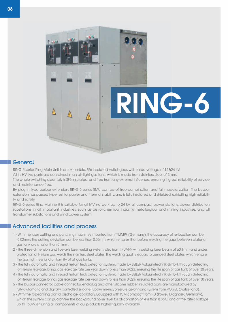
RING-6 series Ring Main Unit is an extensible, SF6 insulated switchgear, with rated voltage of 12&24 kV.All its HV live parts are contained in an air-tight gas tank, which is made from stainless steel of 3mm.The whole switching assembly is SF6 insulated, and free from any external influence, ensuring it great reliability of service and maintenance free.By plug-in type busbar extension, RING-6 series RMU can be of free combination and full modularization. The busbar extension has passed type test for power and thermal stability, and is fully insulated and shielded, exhibiting high reliabili-ty and safety. RING-6 series Ring Main unit is suitable for all MV network up to 24 kV, all compact power stations, power distribution substations in all important industries, such as petrol-chemical industry, metallurgical and mining industries, and all transformer substations and wind power system.
1 - With the laser cutting and punching machines imported from TRUMPF (Germany), the accuracy of re-location can be 0.02mm; the cutting deviation can be less than 0.05mm, which ensures that before welding the gaps between plates of gas tank are smaller than 0.1mm.2 - The three-dimension and five-axis laser welding system, also from TRUMPF, with welding laser beam of φ0.1mm and under protection of Helium gas, welds the stainless steel plates, the welding quality equals to bended steel plates, which ensure the gas tightness and uniformity of all gas tanks.3 - The fully automatic and integral helium leak detection system, made by SEILER Vakuumtechnik GmbH, through detecting of Helium leakage, brings gas leakage rate per year down to less than 0.02%, ensuring the life span of gas tank of over 30 years.4 - The fully automatic and integral helium leak detection system, made by SEILER Vakuumtechnik GmbH, through detecting of Helium leakage, brings gas leakage rate per year down to less than 0.02%, ensuring the life span of gas tank of over 30 years.5 - The busbar connector, cable connector, end-plug and other silicone rubber insulated parts are manufactured by fully-automatic and digitally controlled silicone rubber mixing/pressure gelatinizing system from VOGEL (Switzerland).6 - With the top-ranking partial discharge laboratory, Equipped with ICM compact from PD (Powev Diagnosix, Germany), which the system can guarantee the background noise level for all-condition of less than 0.3pC, and of the rated voltage up to 150kV, ensuring all components of our products highest quality available.
General
08
Advanced facilities and process
General
RING-6
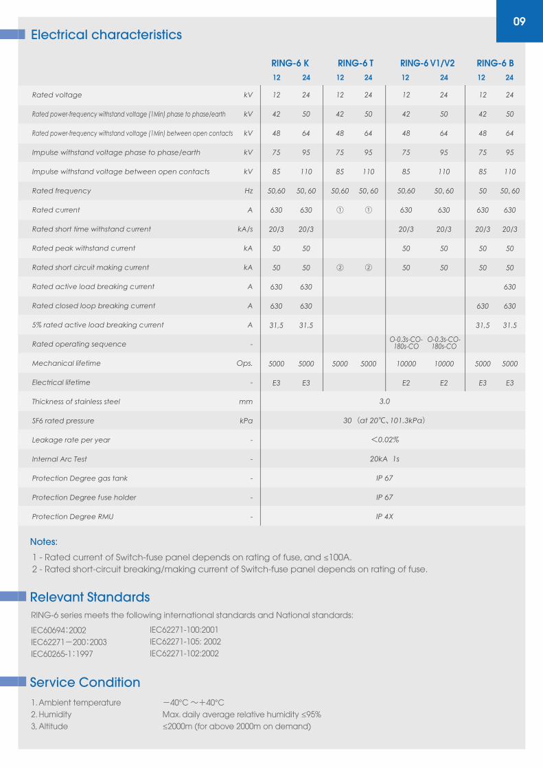
09
IEC60694:2002 IEC62271-200:2003 IEC60265-1:1997
RING-6 series meets the following international standards and National standards:
IEC62271-100:2001 IEC62271-105: 2002 IEC62271-102:2002
Relevant Standards
1. Ambient temperature -40°C ~+40°C 2. Humidity Max. daily average relative humidity ≤95%3, Altitude ≤2000m (for above 2000m on demand)
Service Condition
Rated power-frequency withstand voltage (1Min) phase to phase/earth
Rated voltage
Rated power-frequency withstand voltage (1Min) between open contacts
Impulse withstand voltage phase to phase/earth
Impulse withstand voltage between open contacts
Rated frequency
Rated current
Rated short time withstand current
Rated peak withstand current
Rated short circuit making current
Rated active load breaking current
Rated closed loop breaking current
5% rated active load breaking current
Rated operating sequence
Mechanical lifetime
Electrical lifetime
Thickness of stainless steel
SF6 rated pressure
Leakage rate per year
Internal Arc Test
Protection Degree gas tank
Protection Degree fuse holder
Protection Degree RMU
kV
kV
kV
kV
kV
Hz
A
kA/s
kA
kA
A
A
A
-
Ops.
-
mm
kPa
-
-
-
-
-
12
42
48
75
85
50,60
630
20/3
50
50
630
630
31,5
5000
E3
24
50
64
95
110
50,60
630
20/3
50
50
630
630
31.5
5000
E3
3.0
30 (at 20℃、101.3kPa)
<0.02%
20kA 1s
IP 67
IP 67
IP 4X
12
42
48
75
85
50,60
①
②
5000
24
50
64
95
110
50,60
①
②
5000
12
42
48
75
85
50
630
20/3
50
50
630
31,5
5000
E3
24
50
64
95
110
50,60
630
20/3
50
50
630
630
31.5
5000
E3
12
42
48
75
85
50,60
630
20/3
50
50
O-0.3s-CO-180s-CO
10000
E2
24
50
64
95
110
50,60
630
20/3
50
50
O-0.3s-CO-180s-CO
10000
E2
Electrical characteristics
RING-6 K12 24 12 24 12 2412 24
RING-6 T RING-6 V1/V2 RING-6 B
Notes:
1 - Rated current of Switch-fuse panel depends on rating of fuse, and ≤100A. 2 - Rated short-circuit breaking/making current of Switch-fuse panel depends on rating of fuse.
K
V
10
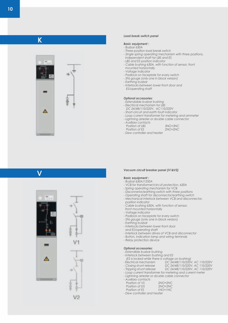
Basic equipment :- Busbar 630A- Three-position load break switch- Single spring operating mechanism with three positions, independent shaft for LBS and ES- LBS and ES position indicator- Cable bushing 630A, with function of sensor, front mounted horizontally- Voltage indicator - Padlock on faceplate for every switch- SF6 gauge (only one in block version)- Earthing busbar - Interlocks between lower front door and ES/operating shaft
Optional accessories:- Extendable busbar bushing- Electrical mechanism for LBS DC 24/48/110/220V, AC110/220V - Short-circuit and earth fault indicator- Loop current transformer for metering and ammeter- Lightning arrester or double cable connector- Auxiliary contacts Position of LBS 3NO+3NC Position of ES 2NO+2NC - Dew controller and heater
Load break switch panel
Optional accessories:- Extendible busbar bushing- Interlock between bushing and ES (ES is locked while there is voltage on bushing)- Electrical mechanism DC 24/48/110/220V, AC 110/220V- Closing shunt release DC 24/48/110/220V, AC 110/220V- Tripping shunt release DC 24/48/110/220V, AC 110/220V- Loop current transformer for metering and current meter- Lightning arrester or double cable connector- Auxiliary contacts Position of VS 2NO+2NC Position of DS 2NO+2NC Position of ES 1NO+1NC- Dew controller and heater
Basic equipment :- Busbar 630A/1250A - VCB for transformer/circuit protection, 630A- Spring operating mechanism for VCB - Disconnetor/earthing switch with three positions- Operating shaft for disconnector/earthing switch - Mechanical interlock between VCB and disconnector, position indicator - Cable bushing 630A, with function of sensor, front mounted horizontally- Voltage indicator - Padlock on faceplate for every switch - SF6 gauge (only one in block version)- Earthing busbar - Interlocks between lower front door and ES/operating shaft - Interlock between drives of VCB and disconnector - Button, indication lamp and wiring terminals- Relay protection device
Vacuum circuit breaker panel (V1&V2)
T
B
11
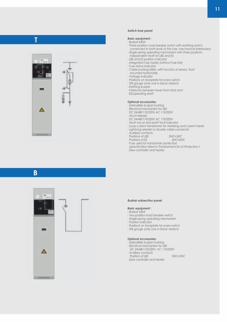
Switch-fuse panel
Basic equipment :- Busbar 630A- Three-position Load breaker switch with earthing switch connected to both ends of the fuse, mechanical interlocked - Single-spring operating mechanism with three positions independent shaft for LBS and ES- LBS and ES position indicator- Integrated fuse holder (without fuse link)- Fuse status indicator - Cable bushing 630A, with function of sensor, front mounted horizontally- Voltage indicator - Padlock on faceplate for every switch - SF6 gauge (only one in block version)- Earthing busbar - Interlocks between lower front door and ES/operating shaft
Optional accessories:- Extendible busbar bushing- Electrical mechanism for LBS DC 24/48/110/220V,AC 110/220V - Shunt release DC 24/48/110/220V,AC 110/220V - Short-circuit and earth fault indicator - Loop current transformer for metering and current meter - Lightning arrester or double cable connector- Auxiliary contacts Positions of LBS 3NO+3NC Positions of ES 2NO+2NC- Fuse used for transformer protection (specification listed in Transformer/Circuit Protection )- Dew controller and heater
Busbar subsection panel
Basic equipment :- Busbar 630A- Two-position load breaker switch- Single-spring operating mechanism- Position indicator- Padlock on faceplate for every switch- SF6 gauge (only one in block version)
Optional accessories:- Extendible busbar bushing- Electrical mechanism for LBS DC 24/48/110/220V, AC 110/220V - Auxiliary contacts Position of LBS 2NO+2NC- Dew controller and heater
C
M
12
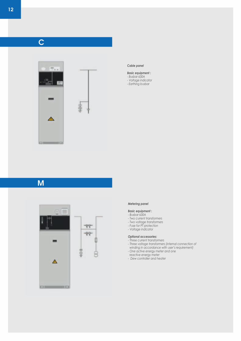
Metering panel
Basic equipment :- Busbar 630A- Two current transformers- Two voltage transformers - Fuse for PT protection- Voltage indicator
Optional accessories:- Three current transformers - Three voltage transformers (internal connection of winding in accordance with user’s requirement)- One active energy meter and one reactive energy meter- Dew controller and heater
Cable panel
Basic equipment :- Busbar 630A- Voltage indicator- Earthing busbar
13
Primary DiagramDimension (W x D x H mm) / Weight (kg)
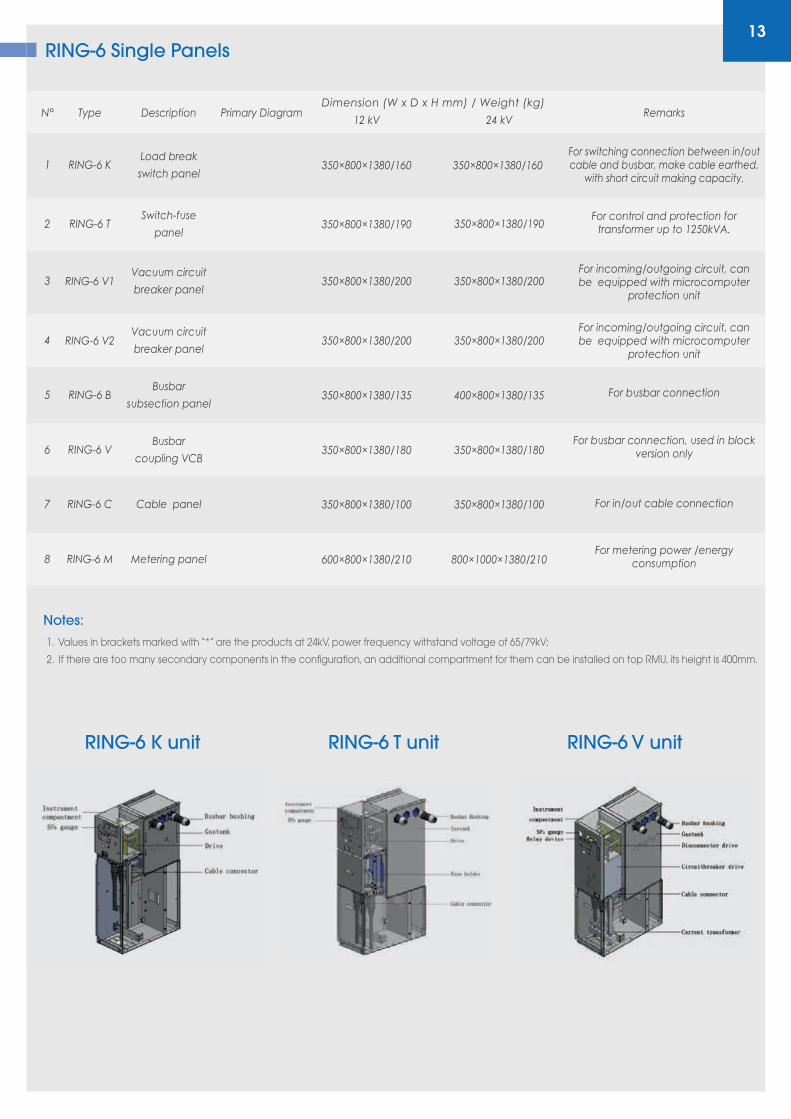
RING-6 Single Panels
TypeN° Description12 kV 24 kV
Remarks
RING-6 K1Load break
switch panel350×800×1380/160
For switching connection between in/out cable and busbar, make cable earthed,
with short circuit making capacity.
RING-6 T2Switch-fuse
panel350×800×1380/190
For control and protection for transformer up to 1250kVA.
RING-6 V13Vacuum circuit
breaker panel350×800×1380/200
For incoming/outgoing circuit, can be equipped with microcomputer
protection unit
RING-6 V24Vacuum circuit
breaker panel350×800×1380/200
For incoming/outgoing circuit, can be equipped with microcomputer
protection unit
RING-6 B5Busbar
subsection panel400×800×1380/135 For busbar connection
RING-6 V6Busbar
coupling VCB350×800×1380/180
For busbar connection, used in block version only
RING-6 C7 Cable panel 350×800×1380/100 For in/out cable connection
RING-6 M8 Metering panel
350×800×1380/160
350×800×1380/190
350×800×1380/200
350×800×1380/200
350×800×1380/135
350×800×1380/180
350×800×1380/100
600×800×1380/210 800×1000×1380/210For metering power /energy
consumption
Notes:
RING-6 K unit RING-6 T unit RING-6 V unit
1. Values in brackets marked with “*” are the products at 24kV, power frequency withstand voltage of 65/79kV;
2. If there are too many secondary components in the configuration, an additional compartment for them can be installed on top RMU, its height is 400mm.
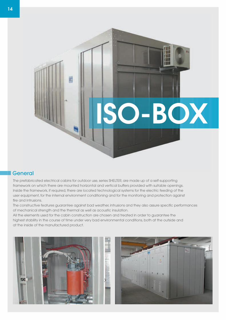
The prefabricated electrical cabins for outdoor use, series SHELTER, are made up of a self-supportingframework on which there are mounted horizontal and vertical buffers provided with suitable openings.Inside the framework, if required, there are located technological systems for the electric feeding of theuser equipment, for the internal environment conditioning and for the monitoring and protection againstfire and intrusions.The constructive features guarantee against bad weather, intrusions and they also assure specific performancesof mechanical strength and the thermal as well as acoustic insulation.All the elements used for the cabin construction are chosen and treated in order to guarantee thehighest stability in the course of time under very bad environmental conditions, both at the outside andat the inside of the manufactured product.
General
14
General
ISO-BOX
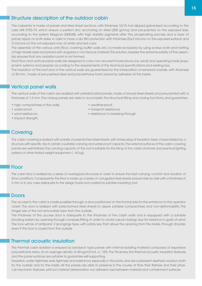
The carpentry is made of panels and steel sheet sections, with thickness 15/10, hot-dipped galvanized according to the rules UNI 5753-75, which ensure a perfect zinc anchoring on steel (200 gr/mq) and pre-painted on the exposed side, according to the system Magona 3000/80, with high stability pigments after the phosphating process and a layer of primer apply on both sides, in oder to have a dry film protection with thickness 25±3 microns on the exposed surface and 3 microns on the not exposed one, of white and red color.The assembly of the various units (floor, covering, buffer walls, etc.) is made exclusively by using screws, bolts and riveting of high tensile steel and joined with angulars in non-ferrous material. This solution, besides the extreme solidity of the assem-bly, ensures that any oxidation point is not formed.Roof, floor and vertical panel walls are designed to carry non-recurrent loads (snow, ice, wind) and operating loads (equi-pment, systems and people) according to the requirements of the technical specifications and existing law.The insulation of the roof and of the vertical walls are guaranteed by the interposition of sandwich panels, with thickness of 30 mm , made of pre-painted steel and polyurethane foam joined by adhesive at the inside.
Structure description of the outdoor cabin
The vertical walls of the cabin are realized with prefabricated panels, made of zinced steel sheets and pre-painted with a thickness of 1.5 mm. The closing panels are able to accomplish the structural lifting and closing functions, and guarantee:
• high compactness of the walls;• water-proof;• wind resistance ;• impact strength;
• weather-proof;• transport resistance;• resistance to breaking through.
Vertical panel walls
The cabin covering is realized with panels of press-formed steel sheets, with interposing of insulation layer, characterized by a structure with specific ribs to obtain a suitable carrying and water-proof capacity. The external surfaces of the cabin covering panels are well-finished, the carrying capacity of the roof is suitable for the fixing of the cable channels and eventual lighting systems or other limited weight equipment (~ 60 kg).
Covering
The cabin floor is realized by a series of overlapped structures in order to ensure the best carrying, comfort and duration of time conditions. Consequently the floor is made up a series of corrugated steel sheets placed side by side with a thickness of 2 mm or in any case adequate to the design loads and coated by suitable insulating mat.
Floor
15
The access to the cabin is made possible through a door positioned on the frontal side for the entrance to the operator closet. The door is realized with press-formed steel sheets to assure suitable compactness and non-deformability. The hinges are of the not removable type from the outside .The thickness of the access door is adequate to the thickness of the cabin walls and is equipped with a suitable blocking system by opening through compass fitting, in order to avoid casual closings due for instance to gusts of wind. The lock will be of antipanic 3 spongings type, with safety key that allows the opening from the inside, through shackle, even if the lock is closed from the outside
Doors
The thermal cabin isolation is ensured by sandwich type panels with internal isolating material composed of expansive polyurethane resins, at an average density of 40 kg/m3 toll. +/- 10%. The thickness, the thermal acoustic insulation features and the panel surfaces are suitable to guarantee self-supporting,insulation, water tightness, leak tightness and resistance, especially in the joints, and are a pleasant aesthetic solution, both for the outside and for the inside. All the panels are able to preserve in the course of time their flatness and their physi-cal-mechanic features, without material deterioration nor adhesion loss between material and containment surfaces.
Thermal acoustic insulation
16
All the surfaces of the steel elements are designed for both external and internal use, of smooth type or variously confor-med, will be protected against the corrosion phenomena with proper treatment processes accordingly to their particu-lar exposure condition. The fixing elements will generally be of stainless steel type, galvanized passivated, chromed or in any case treated against corrosion before the use in the cabin. For the metal panels there will be preferably chosen pre-painted steel sheets realized with methods and features depending on the used thicknesses and the installation (outside or inside). The manufacturer will provide the technico-chromatic specifications for any little additional touches. For the steel sheets with a thickness superior than 3÷3.5 mm, for the materials expected elsewhere and on explicit custo-mer’s demand, as well as for eventual small surfaces of press-formed or section steel sheets, there will be executed “spray” painting on sandblasted base and/or however suitably prepared by adequate primer treatment.
Rust-inhibitive protection of the constructive elements against atmospheric agents
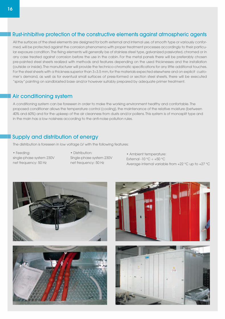
A conditioning system can be foreseen in order to make the working environment healthy and confortable. Theproposed conditioner allows the temperature control (cooling), the maintenance of the relative moisture (between40% and 60%) and for the upkeep of the air cleanness from dusts and/or pollens. This system is of monosplit type andin the main has a low noisiness according to the anti-noise pollution rules.
Air conditioning system
The distribution is foreseen in low voltage LV with the following features:
• Feeding:single-phase system 230Vnet frequency: 50 Hz
• Distribution:Single-phase system 230Vnet frequency: 50 Hz
• Ambient temperature:External -10 °C ÷ +50 °CAverage internal variable from +22 °C up to +27 °C
Supply and distribution of energy
17
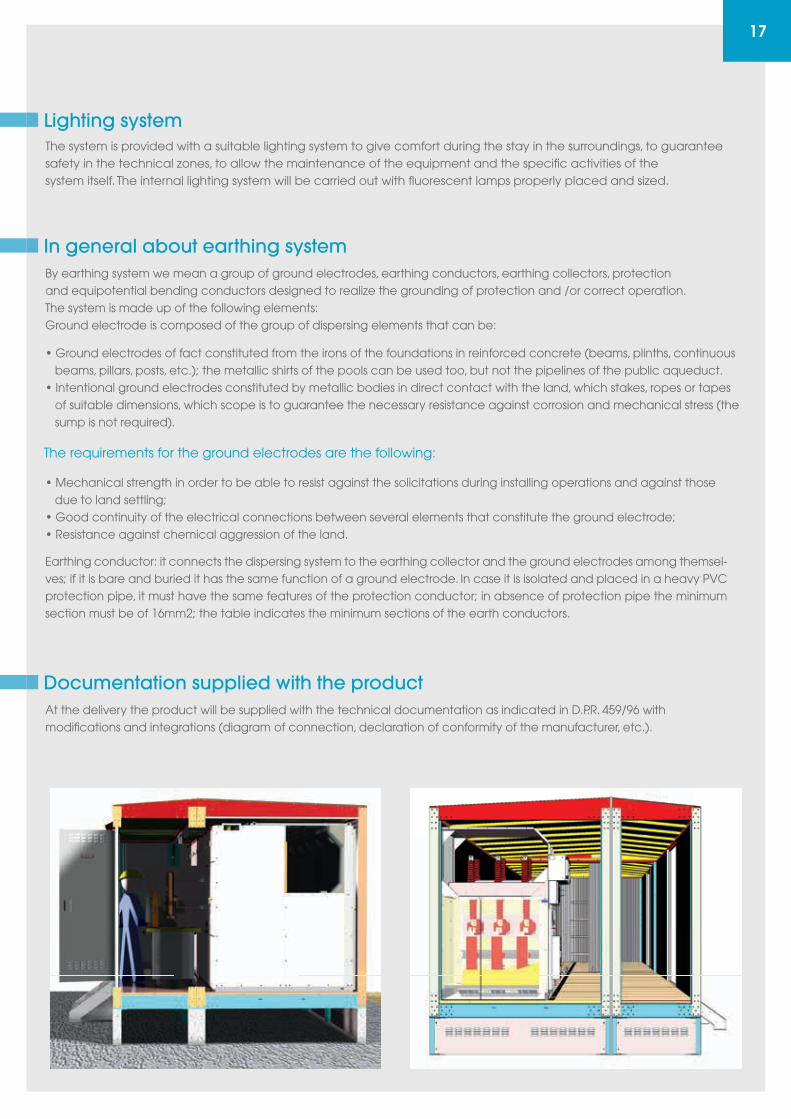
The system is provided with a suitable lighting system to give comfort during the stay in the surroundings, to guaranteesafety in the technical zones, to allow the maintenance of the equipment and the specific activities of thesystem itself. The internal lighting system will be carried out with fluorescent lamps properly placed and sized.
Lighting system
By earthing system we mean a group of ground electrodes, earthing conductors, earthing collectors, protectionand equipotential bending conductors designed to realize the grounding of protection and /or correct operation.The system is made up of the following elements:Ground electrode is composed of the group of dispersing elements that can be:
• Mechanical strength in order to be able to resist against the solicitations during installing operations and against those due to land settling;• Good continuity of the electrical connections between several elements that constitute the ground electrode;• Resistance against chemical aggression of the land.
Earthing conductor: it connects the dispersing system to the earthing collector and the ground electrodes among themsel-ves; if it is bare and buried it has the same function of a ground electrode. In case it is isolated and placed in a heavy PVC protection pipe, it must have the same features of the protection conductor; in absence of protection pipe the minimum section must be of 16mm2; the table indicates the minimum sections of the earth conductors.
• Ground electrodes of fact constituted from the irons of the foundations in reinforced concrete (beams, plinths, continuous beams, pillars, posts, etc.); the metallic shirts of the pools can be used too, but not the pipelines of the public aqueduct.• Intentional ground electrodes constituted by metallic bodies in direct contact with the land, which stakes, ropes or tapes of suitable dimensions, which scope is to guarantee the necessary resistance against corrosion and mechanical stress (the sump is not required).
In general about earthing system
The requirements for the ground electrodes are the following:
At the delivery the product will be supplied with the technical documentation as indicated in D.P.R. 459/96 withmodifications and integrations (diagram of connection, declaration of conformity of the manufacturer, etc.).
Documentation supplied with the product
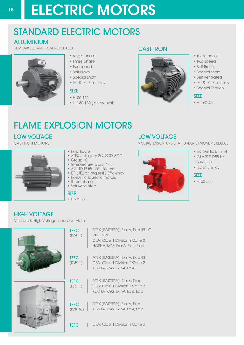
• Single phase • Three phase• Two speed• Self Brake• Special shaft• IE1 & IE2 Efficiency
• H. 56-132• H. 160-180 ( on request) • H. 160-450
• Three phase• Two speed• Self Brake• Special shaft• Self ventilated• IE1 & IE2 Efficiency• Special Tension
SIZE
• Ex-d, Ex-de• ATEX category 2G, 2GD, 3GD• Group IIC• Temperature class T4-T5• A21-tD IP 55 - 56 - 65 - 66• IE1 ( IE2 on request ) Efficiency• Ex-nA no sparking motors• Three phase• Self ventilated
• H. 63-355SIZE
ALLUMINIUM
LOW VOLTAGE
HIGH VOLTAGEMedium & High Voltage Induction Motor
LOW VOLTAGE
CAST IRON
SIZE
• Ex II2G, Ex D IIB T4• CLASS F IP55 Hz 50/60 EFF1• IE2 Efficiency
• H. 63-355
SIZE
18
REMOVABLE AND REVERSIBLE FEET
STANDARD ELECTRIC MOTORS
FLAME EXPLOSION MOTORS
CAST IRON MOTORS SPECIAL TENSION AND SHAFT UNDER CUSTOMER’S REQUEST
ATEX (BASEEFA): Ex nA, Ex d IIB, IICPTB: Ex dCSA: Class 1 Division 2/Zone 2HOSHA, KGS: Ex nA. Ex e, Ex d
ATEX (BASEEFA): Ex nA, Ex d IIBCSA: Class 1 Division 2/Zone 2KOSHA, KGS: Ex nA, Ex e
ATEX (BASEEFA): Ex nA, Ex pCSA: Class 1 Division 2/Zone 2KOSHA, KGS: Ex nA, Ex e, Ex p
TEFC(IC411)
(IC511)
(IC611)
(IC81W)
TEFC
TEFC
TEFC
TEFC
ATEX (BASEEFA): Ex nA, Ex pKOSHA, KGS: Ex nA, Ex e, Ex p
CSA: Class 1 Division 2/Zone 2
ELECTRIC MOTORS
19
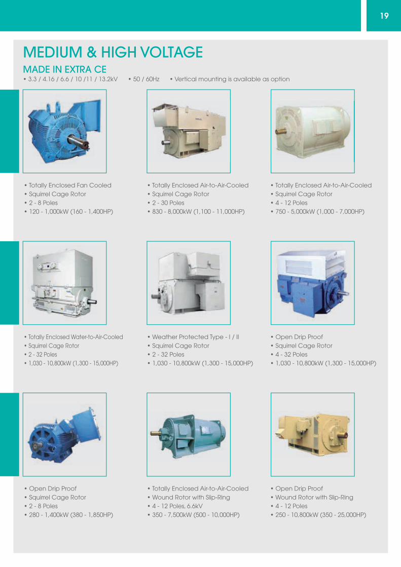
• 3.3 / 4.16 / 6.6 / 10 /11 / 13.2kV • 50 / 60Hz • Vertical mounting is available as option
• Totally Enclosed Fan Cooled• Squirrel Cage Rotor• 2 - 8 Poles• 120 - 1,000kW (160 - 1,400HP)
• Totally Enclosed Air-to-Air-Cooled• Squirrel Cage Rotor• 2 - 30 Poles• 830 - 8,000kW (1,100 - 11,000HP)
• Totally Enclosed Air-to-Air-Cooled• Squirrel Cage Rotor• 4 - 12 Poles• 750 - 5,000kW (1,000 - 7,000HP)
MEDIUM & HIGH VOLTAGEMADE IN EXTRA CE
• Totally Enclosed Water-to-Air-Cooled• Squirrel Cage Rotor• 2 - 32 Poles• 1,030 - 10,800kW (1,300 - 15,000HP)
• Weather Protected Type - I / II• Squirrel Cage Rotor• 2 - 32 Poles• 1,030 - 10,800kW (1,300 - 15,000HP)
• Open Drip Proof• Squirrel Cage Rotor• 4 - 32 Poles• 1,030 - 10,800kW (1,300 - 15,000HP)
• Open Drip Proof• Squirrel Cage Rotor• 2 - 8 Poles• 280 - 1,400kW (380 - 1,850HP)
• Totally Enclosed Air-to-Air-Cooled• Wound Rotor with Slip-Ring• 4 - 12 Poles, 6.6kV• 350 - 7,500kW (500 - 10,000HP)
• Open Drip Proof• Wound Rotor with Slip-Ring• 4 - 12 Poles• 250 - 10,800kW (350 - 25,000HP)

I N T E R N A T I O N A L
IBS - International Business & Services s.r.l.
Via Rodi 69 - 25124 Brescia (BS) - ItalyTel. +39 345 5926528 - Tel. +39 345 5926553 - Fax. +39 030 7771508
Email [email protected] Web www.ibsitaly.itN. Reg. Imprese / Cod. Fisc / P. IVA 03394520989
REA BS 530486
Top Related