


Languages
Pages
Legal


ISO 9001
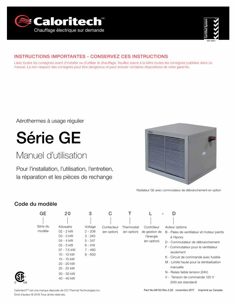
GE heater with optional disconnect
Part No.MI153.Rev.5.02 November 2017 Printed in Canada
GE SeriesOwner’s Manual
Regular Duty Forced Air Unit Heaters
Installation, Operation, & Maintenance Instructions
GE 20 3 C T L - D
Model Series
Kilowatts02 - 2 kW03 - 3 kW04 - 4 kW05 - 5 kW07 - 7.5 kW10 - 10 kW15 - 15 kW20 - 20 kW25 - 25 kW
30 - 30 kW 40 - 40 kW
Voltage2 - 2083 - 2405 - 3476 - 4167 - 4808 - 600
Contactor(Optional)
Thermostat(Optional)
Other Options
B - Epoxy painted fan blade and motor
D - Disconnect switch
F - Fan only switch
K - Fused control circuit
M - Manual reset high limit
N - Low voltage relay (24V)
V - 120V control voltage (240V is standard)
Model Coding
Energy Management
Controller(Optional)
C US
®
IMPORTANT INSTRUCTIONS - SAVE THESE INSTRUCTIONSRead all instructions before installing or using the heater. Please adhere to instructions published in this manual. Failure to do so may be dangerous and may void certain provisions of your warranty.
Caloritech™ is a registered trademark of CCI Thermal Technologies Inc.
Copyright© 2016. All rights reserved.
TABLE OF CONTENTS
A. Important Notices 3
B. Installation 4
B.1 Location ........................................................................................................................ 4
B.2 Mounting ...................................................................................................................... 4
B.3 Electrical ....................................................................................................................... 5
B.4 Sample Wiring Schematics - GE Series Heater............................................................. 5
C. Operation 8
C.1 General .........................................................................................................................8
D. Repair & Replacement 8
D.1 Heating Elements ..........................................................................................................8
D.2 Fan ...............................................................................................................................8
D.3 Thermal Cut-Out ...........................................................................................................8
E. Parts List 9
F. Troubleshooting Tips 11
F.1 Heater is not operating. .................................................................................................11
F.2 Contactor is chattering. ................................................................................................11
F.3 Contactor is burned or welded .....................................................................................11
F.4 Heater cycles on high limit. ...........................................................................................11
F.5 Heater is operating but no heat is present. ...................................................................11
F.6 Heater fan does not operate but the heating elements operate. ...................................11
F.7 The Ground Fault Interrupter (GFI) trips on the main panel, or heater blows fuses. ...... 12
F.8 The fan is turning but very little air comes from the front of the heater. ........................ 12
G. Technical Data 13
H. General Specifications 14
I. Heater Maintenance Instructions 15
3
Important N
otices
A. IMPORTANT NOTICES
CAUTION
CAUTION. This symbol indicates a potentially hazardous situation, which, if not avoided, may result in personal injury or damage to the equipment.
WARNING
WARNING. This symbol indicates an imminently hazardous situation, which, if not avoided, can result in serious injury or damage to the equipment.
WARNING
WARNING. Read and adhere to the following. Failure to do so may result in a risk of fire, electrical shock, and severe or fatal injury. Warranty will be void.
1. Read and follow all instructions in this manual.
2. This heater is intended to be used for commercial and industrial indoor space heating applications.
WARNING
WARNING. Heater is not to be used in hazardous atmospheres where flammable vapors, gases, liquids or other combustible atmospheres are present.
3. Heater is to be connected and serviced only by a qualified electrician.
4. Installation and wiring of the heater must adhere to all applicable codes.
5. Disconnect heater from power supply at disconnect or fuse box before opening enclosures or servicing heater. IF DISCONNECT IS BEING SERVICED, verify power has been disconnected at fuse box or main panel. Lock the switch in the “OFF” (open) position and tag the switch to prevent unexpected power application.
6. Do not operate heater in wet and humid environments.
WARNING
WARNING. Elements get hot during operation. Contact can cause burns.
7. Install and maintain clearances as per this manual.
8. Do not operate the heater in corrosive atmospheres.
9. Use factory replacement parts only.
10. Maximum ambient operating temperature is 40°C (104°F).
11. Do not operate the heater with the louvers deformed or damaged.
12. If there are any questions or concerns regarding the heater, please refer to contact information on the back page of this manual.
13. Follow the recommended maintenance procedures under Section I. Heater Maintenance Instructions, page 15.
4
Inst
alla
tion
B. INSTALLATION
All applicable codes must be adhered to. For optimum performance, the heater should be installed as follows:
B.1 Location
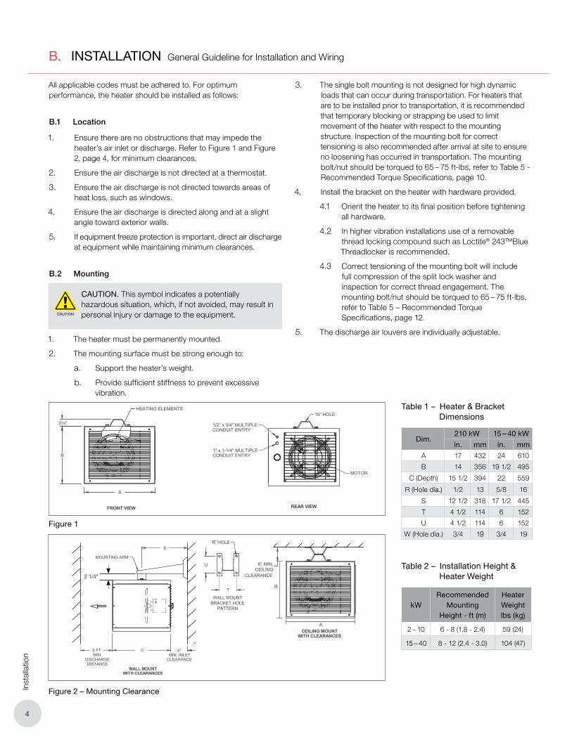
1. Ensure there are no obs tructions that may impede the heater’s air inlet or discharge. Refer to Figure 1 and Figure 2, page 4, for minimum clearances.
2. Ensure the air discharge is not directed at a thermostat.
3. Ensure the air discharge is not directed towards areas of heat loss, such as windows.
4. Ensure the air discharge is directed along and at a slight angle toward exterior walls.
5. If equipment freeze protection is important, direct air discharge at equipment while maintaining minimum clearances.
B.2 Mounting
CAUTION
CAUTION. This symbol indicates a potentially hazardous situation, which, if not avoided, may result in personal injury or damage to the equipment.
1. The heater must be permanently mounted.
2. The mounting surface must be strong enough to:
a. Support the heater’s weight.
b. Provide sufficient stiffness to prevent excessive vibration.
3. The single bolt mounting is not designed for high dynamic loads that can occur during transportation. For heaters that are to be installed prior to transportation, it is recommended that temporary blocking or strapping be used to limit movement of the heater with respect to the mounting structure. Inspection of the mounting bolt for correct tensioning is also recommended after arrival at site to ensure no loosening has occurred in transportation. The mounting bolt/nut should be torqued to 65 – 75 ft-lbs, refer to Table 5 - Recommended Torque Specifications, page 10.
4. Install the bracket on the heater with hardware provided.
4.1 Orient the heater to its final position before tightening all hardware.
4.2 In higher vibration installations use of a removable thread locking compound such as Loctite® 243™Blue Threadlocker is recommended.
4.3 Correct tensioning of the mounting bolt will include full compression of the split lock washer and inspection for correct thread engagement. The mounting bolt/nut should be torqued to 65 – 75 ft-lbs, refer to Table 5 – Recommended Torque Specifications, page 12.
5. The discharge air louvers are individually adjustable.
WALL MOUNTWITH CLEARANCES
FRONT VIEW REAR VIEW
2¼"
B
A
HEATING ELEMENTS
MOTOR
1/2" x 3/4" MULTIPLECONDUIT ENTRY
1" x 1-1/4" MULTIPLECONDUIT ENTRY
6"MIN. INLET
WALL MOUNTBRACKET HOLE
PATTERN
CLEARANCE
6 FT C
MOUNTING ARM
S
T
U
MIN.DISCHARGEDISTANCE
'R' HOLE
CEILING MOUNTWITH CLEARANCES
'W' HOLE
6" MIN.CEILING
CLEARANCE
Table 1 – Heater & Bracket Dimensions
Dim.210 kW 15 – 40 kW
in. mm in. mmA 17 432 24 610
B 14 356 19 1/2 495
C (Depth) 15 1/2 394 22 559
R (Hole dia.) 1/2 13 5/8 16
S 12 1/2 318 17 1/2 445
T 4 1/2 114 6 152
U 4 1/2 114 6 152
W (Hole dia.) 3/4 19 3/4 19
Table 2 – Installation Height & Heater Weight
kWRecommended
Mounting Height - ft (m)
Heater Weightlbs (kg)
2 – 10 6 - 8 (1.8 - 2.4) 59 (24)
15 – 40 8 - 12 (2.4 - 3.0) 104 (47)
Figure 1
General Guideline for Installation and Wiring
Figure 2 – Mounting Clearance
WALL MOUNTWITH CLEARANCES
FRONT VIEW REAR VIEW
2¼"
B
A
HEATING ELEMENTS
MOTOR
1/2" x 3/4" MULTIPLECONDUIT ENTRY
1" x 1-1/4" MULTIPLECONDUIT ENTRY
6"MIN. INLET
WALL MOUNTBRACKET HOLE
PATTERN
CLEARANCE
6 FT C
MOUNTING ARM
S
T
U
MIN.DISCHARGEDISTANCE
'R' HOLE
CEILING MOUNTWITH CLEARANCES
'W' HOLE
6" MIN.CEILING
CLEARANCE
2 1/4"
B
A

5
Installation
B.3 Electrical
WARNING
WARNING. Disconnect heater from power supply at disconnect or fuse box before opening enclosures or servicing heater.
Lock the switch in the “OFF” (open) position and tag the switch to prevent unexpected power application.
This heater should only be serviced by qualified personnel with electrical heating equipment experience.
Install and use the heater in accordance with local codes and this manual.
B.3.1 General
1. Use only approved copper conductors for installation. Refer to Section G. Technical Data, page 13 and heater data plate for conductor rating.
2. The power supply may be single or three phase as shown on the nameplate. Wiring diagrams are on the inside of the terminal compartment cover (or refer to Section B.4 Sample Wiring Schematics - GE Series Heater, page 5 – 7). Connection box volume: 2 – 10 kW: 9893 cm³, 15 – 40 kW: 32333 cm³.
B.3.2 Field Wiring
1. Heater is supplied with an enclosure that has standard trade size conduit openings to accommodate the line conductors or external thermostat connection. Two 1/2" or 3/4" conduit knockouts are located on the 2 – 10 kW units. Two 1/2", 3/4", 1" or 1-1/4" conduit knockouts are located on the 15 – 40 kW units.
2. Heater may be supplied with a factory-installed built-in room thermostat. On heaters not supplied with this option, a remote thermostat is required. Connect the remote thermostat conductors to the terminal block, refer to Section B.4 Sample Wiring Schematics - GE Series Heater, page 5 – 7. Remote thermostats are available from the factory. Any thermostat used with this heater must be:
2.1 UL listed or CSA approved
2.2 Rated for 240 volts minimum and 5 amps minimum.
3. Grounding: a ground screw with a cup washer is located beside the terminal block. Ensure the unit is properly grounded before energizing.
4. Models without a built-in contactor should have the limit switch wired in the control circuit of an external contactor, and for three phase supply, this control circuit should be connected to L2 and L3 which feed the centre heating element, refer to Figure 3E, page 7. The limit switch is rated 600 volts, 10 amps resistive.
B.3.3 Final Inspection
Before application of electrical power:
4.1 Check that all connections are secured and comply with the applicable code requirements.
4.2 Confirm supply voltage is compatible with the data plate specifications.
4.3 Remove any foreign objects from the heater.
4.4 Ensure all external fittings and enclosure covers are secured.
4.5 Ensure fan rotates freely.
4.6 If equipped, ensure manual reset thermal cut-out has been reset.
B.4 Sample Wiring Schematics - GE Series Heater
If the wiring schematics of Figures 3A – 3F, page 5 – 7, do not match your configuration, check the inside access panel of the unit for specific wiring schematic. Alternatively, all wiring schematics are available online at: www.caloritech.com.
Figure 3A – GE Series 2 – 10 kW wiring schematic with hi-limit option. 208V and 240V models.

6
Inst
alla
tion
Figure 3B – GE Series 2 – 10 kW wiring schematic with hi-limit and fused control circuit options. 208/240/480/600V models.
Figure 3C – GE Series 2 – 10 kW wiring schematic with hi-limit, contactor, built-in thermostat, fan only switch options. 208 - 240V models.
Figure 3D – GE Series 2 – 10 kW wiring schematic with hi-limit, contactor, built-in thermostat, fan only switch, transformer and fused control circuit options. 208 – 600V models.
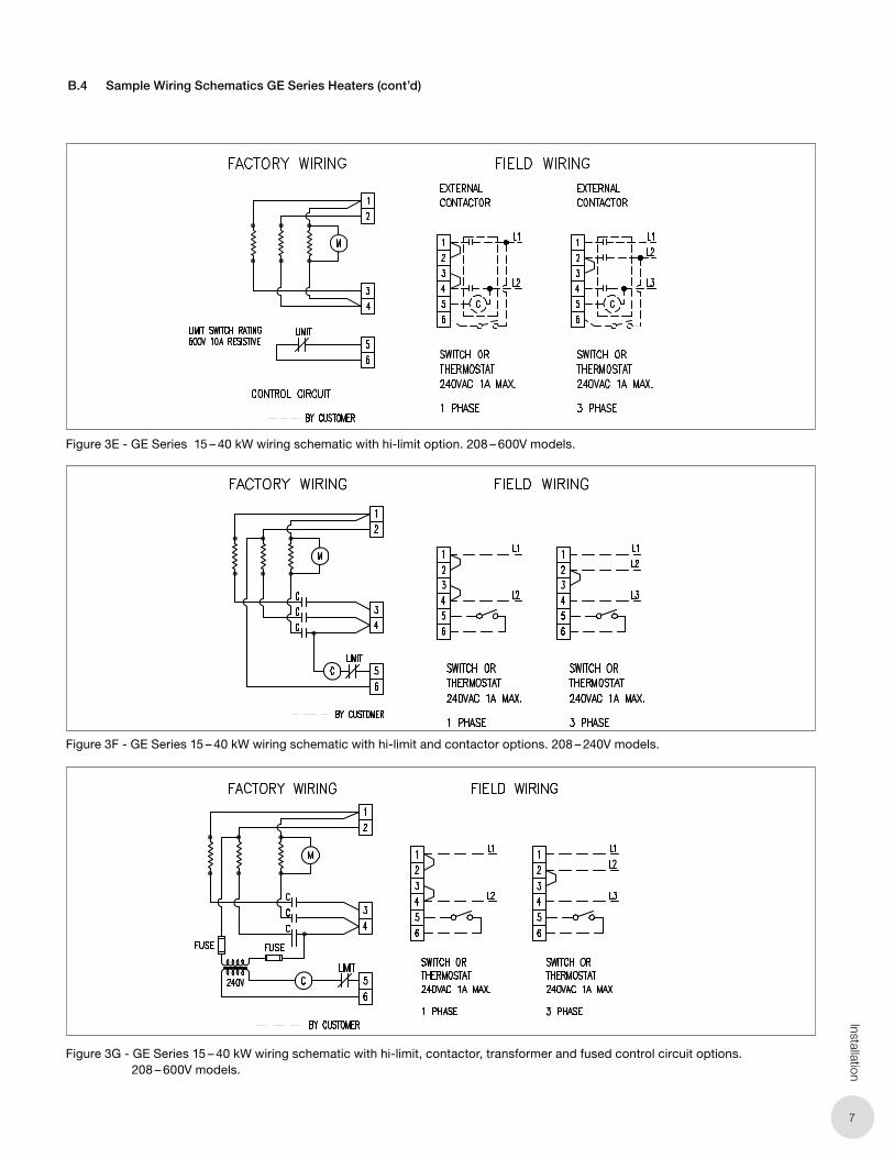
B.4 Sample Wiring Schematics GE Series Heaters (cont’d)
If the wiring schematics of Figures 3A – 3F, page 5 – 7, do not match your configuration, check the inside access panel of the unit for specific wiring schematic. Alternatively, all wiring schematics are available online at: www.caloritech.com.
7
Installation
B.4 Sample Wiring Schematics GE Series Heaters (cont’d)
Figure 3E - GE Series 15 – 40 kW wiring schematic with hi-limit option. 208 – 600V models.
Figure 3F - GE Series 15 – 40 kW wiring schematic with hi-limit and contactor options. 208 – 240V models.
Figure 3G - GE Series 15 – 40 kW wiring schematic with hi-limit, contactor, transformer and fused control circuit options. 208 – 600V models.
8
Ope
ratio
n, R
epai
r &
Rep
lace
men
t
C. OPERATION
C.1 General
1. To operate heater, ensure power supply is properly connected as specified in the wiring schematic (refer to Figures 3A – 3F, page 5 – 7).
2. If unit is equipped with an optional thermostat, ensure the thermostat is set above the ambient temperature.
3. If unit is equipped with the optional “FAN ONLY” switch, ensure the switch is in the “ON” position. Note: If the switch is in the “FAN ONLY” position, only the fan will energize, not the heating elements.
4. During normal operation, the thermal cut-out control should not cycle the heater ON and OFF. If cycling occurs, check to see if there is an airflow blockage. If there are no obstructions, the heater must be examined by qualified personnel to determine the cause of the thermal cut-out cycling.
5. Operate the unit for a minimum of 10 minutes to allow the heating elements to reach a steady state. If no warm air is discharged from the heater, shut off the unit and see Section F. Troubleshooting Tips, page 11.
D. REPAIR & REPLACEMENT
WARNING
WARNING. Disconnect heater from power supply at disconnect or fuse box before opening enclosures or servicing heater.
Lock the switch in the “OFF” (open) position and tag the switch to prevent unexpected power application.
This heater should only be serviced by qualified personnel with electrical heating equipment experience.
Install and use the heater in accordance with local codes and this manual.
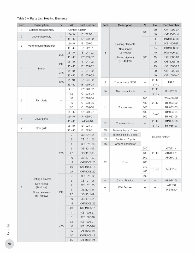
NOTE: ONLY USE FACTORY SUPPLIED REPLACEMENT PARTS OF THE SAME SPECIFICATION. REFER TO TABLE 3 – PARTS LIST: HEATING ELEMENTS, PAGE 10 FOR COMPLETE LISTING OF AVAILABLE PARTS.
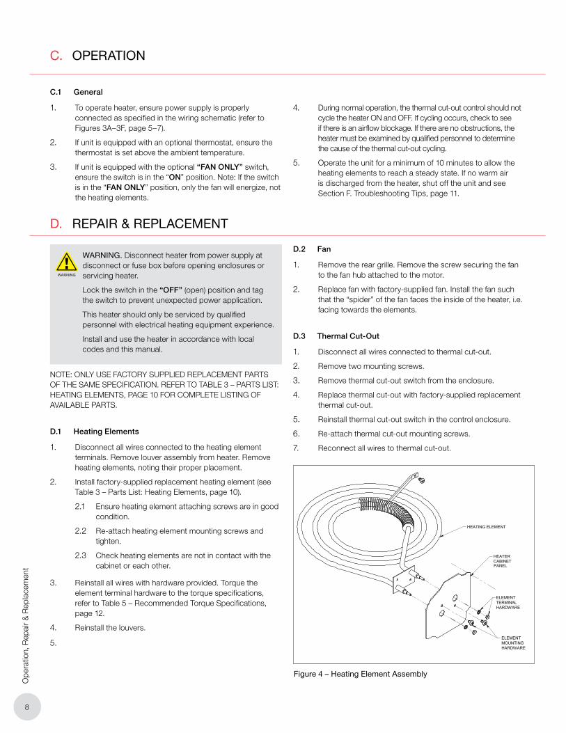
D.1 Heating Elements
1. Disconnect all wires connected to the heating element terminals. Remove louver assembly from heater. Remove heating elements, noting their proper placement.
2. Install factory-supplied replacement heating element (see Table 3 – Parts List: Heating Elements, page 10).
2.1 Ensure heating element attaching screws are in good condition.
2.2 Re-attach heating element mounting screws and tighten.
2.3 Check heating elements are not in contact with the cabinet or each other.
3. Reinstall all wires with hardware provided. Torque the element terminal hardware to the torque specifications, refer to Table 5 – Recommended Torque Specifications, page 12.
4. Reinstall the louvers.
5.
D.2 Fan
1. Remove the rear grille. Remove the screw securing the fan to the fan hub attached to the motor.
2. Replace fan with factory-supplied fan. Install the fan such that the “spider” of the fan faces the inside of the heater, i.e. facing towards the elements.
D.3 Thermal Cut-Out
1. Disconnect all wires connected to thermal cut-out.
2. Remove two mounting screws.
3. Remove thermal cut-out switch from the enclosure.
4. Replace thermal cut-out with factory-supplied replacement thermal cut-out.
5. Reinstall thermal cut-out switch in the control enclosure.
6. Re-attach thermal cut-out mounting screws.
7. Reconnect all wires to thermal cut-out.
HEATER CABINETPANEL
ELEMENT TERMINALHARDWARE
ELEMENT MOUNTING HARDWARE
HEATING ELEMENT
Figure 4 – Heating Element Assembly
9
Parts List
2
7
3
11
12
10
6
13
4
5
158
1
14
16
9
PARTS LISTITEM DESCRIPTION
1 CABINET BOX ASSEMBLY
2 LOUVER ASSEMBLY
3 MOTOR MOUNT
4 MOTOR
5 FAN BLADE
6 COVER PANEL
7 REAR GRILLE
8 NON-FINNED (2-10 KW), FINNED ELEMENT (15-40 KW)
9 THERMOSTAT - SPST
10 THERMOSTAT KNOB
11 TRANSFORMER
12 THERMAL CUT-OUT
13 TERMINAL BLOCK, 6 POLE
14 TERMINAL BLOCK, 3 POLE
15 CONTACTOR, 3 POLE
16 GROUND CONNECTOR
17 FUSE
17
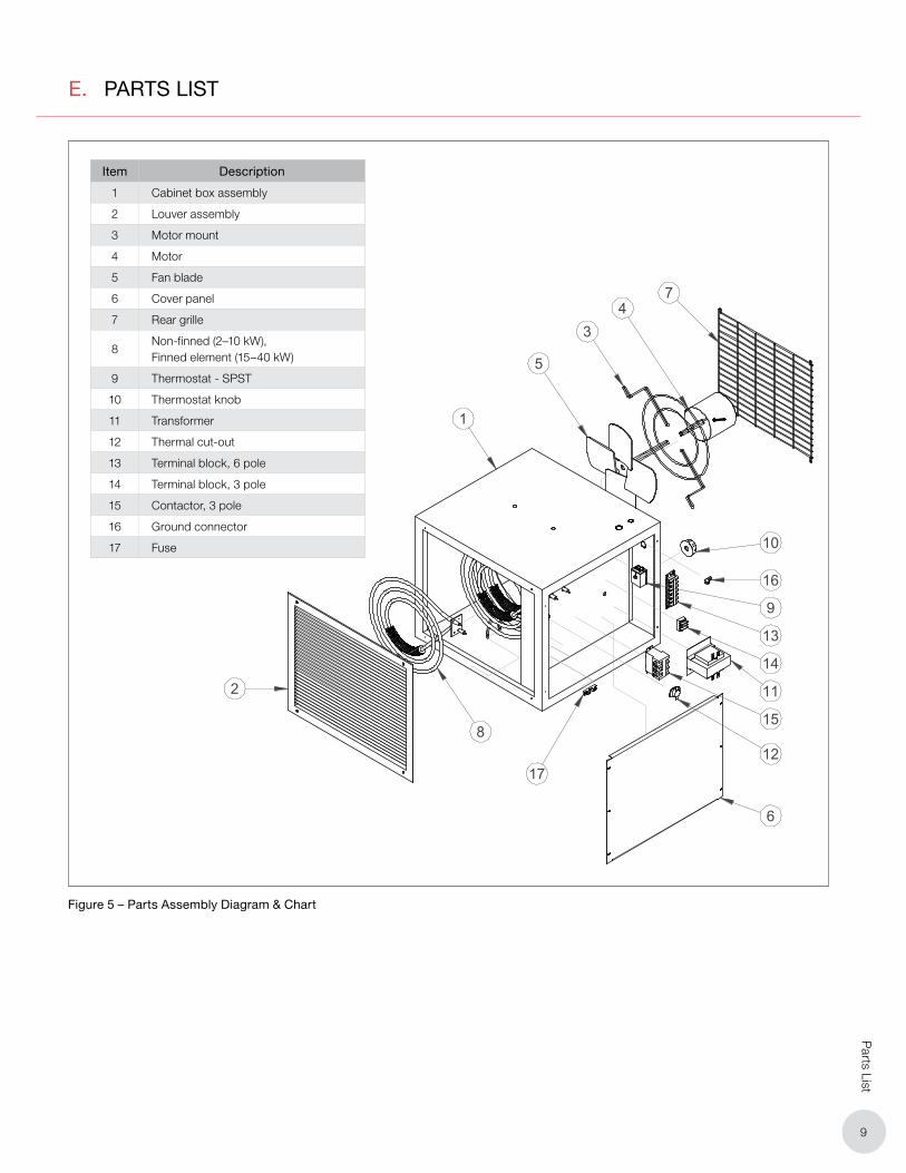
E. PARTS LIST
Item Description
1 Cabinet box assembly
2 Louver assembly
3 Motor mount
4 Motor
5 Fan blade
6 Cover panel
7 Rear grille
8Non-finned (2–10 kW), Finned element (15–40 kW)
9 Thermostat - SPST
10 Thermostat knob
11 Transformer
12 Thermal cut-out
13 Terminal block, 6 pole
14 Terminal block, 3 pole
15 Contactor, 3 pole
16 Ground connector
17 Fuse
Figure 5 – Parts Assembly Diagram & Chart
10
Par
ts L
ist
Item Description V kW Part Number
1 Cabinet box assembly Contact Factory
2 Louver assembly —2 – 10 B11022-01
15 – 40 B11022-02
3 Motor mounting Bracket —2 – 10 B11026-01
15 – 40 B11027-01
4 Motor
2082 – 10 B11041-02
15 – 40 B11059-02
2402 – 10 B11041-02
15 – 40 B11059-02
4802 – 10 B11041-02
15 – 40 B11059-03
6002 – 10 B11041-02
15 – 40 B11059-04
5 Fan blade —
2 – 5 C11028-02
7.5 C11028-03
10 C11028-04
15 C11028-05
20 C11028-06
25 – 40 C11028-07
6 Cover panel —2 – 10 A11050-01
15 – 40 All049-01
7 Rear grille —2 – 10 B11024-01
15 – 40 B11023-01
8
Heating Elements
Non-finned (2–10 kW)
Finned element (15–40 kW)
208
2 IXS11011-01
3 IXS11011-05
4 IXS11011-09
5 IXS11011-13
7.5 IXS11011-18
10 IXS11011-23
15 KXF11008-25
20 KXF11008-16
25 KXF11008-20
240
2 IXS11011-02
3 IXS11011-06
4 IXS11011-05
5 IXS11011-14
7.5 IXS11011-19
10 IXS11011-24
15 KXF11008-26
20 KXF11008-17
480
4 IXS11006-37
5 IXS11006-16
7.5 IXS11006-21
10 IXS11006-26
15 KXF11008-27
20 KXF11008-18
25 KXF11008-21
Item Description V kW Part Number
8
Heating Elements
Non-finned (2–10 kW)
Finned element (15–40 kW)
48030 KXF11008-37
40 KXF11008-14
600
4 IXS11006-38
5 IXS11006-17
7.5 IXS11006-22
10 IXS11006-27
15 KXF11008-28
20 KXF11008-19
25 KXF11008-22
30 KXF11008-38
40 KXF11008-40
9 Thermostat - SPST —2 – 10
FAT 815 – 40
10 Thermostat knob —2 – 10
B11037-0115 – 40
11 Transformer
240
2 – 10
TSK4114-32
480 B11033-02
600 B11033-03
48015 – 40
B11033-04
600 B11033-05
12 Thermal cut-out —2 – 10 B11035-03
15 – 40 B11035-03
13 Terminal block, 6 pole
Contact factory.14 Terminal block, 3 pole
15 Contactor, 3 pole
16 Ground connector
17 Fuse
240
2 – 10
ATQR 1.4
480 ATQR 0.75
600 ATQR 0.75
208
15 – 40 ATQR 1/4240
480
600
— Ceiling Bracket — — A11034-01
— Wall Bracket — —WB 210
WB 1540
Table 3 – Parts List: Heating Elements
11
Troubleshooting Tips
F. TROUBLESHOOTING TIPS
F.1 Heater is not operating.
1. Check all fuses.
2. Check disconnect switch.
3. Check voltage supplied to the heater – refer to the heater data plate for voltage requirements.
4. Check control voltage if transformer is installed.
5. Check thermostat by turning it and check continuity.
6. Check the condition of the disconnect switch if the heater is so equipped. Measure continuity through the disconnect by engaging the switch.
7. Verify that there is a jumper wire present between the terminals as per the wiring schematics (refer to Figures 3A – 3F, page 5 – 7.
8. If problem still exists, contact factory.
F.2 Contactor is chattering.
1. Check supply voltage.2. Check control voltage if transformer is installed.
3. Check wiring connections. Tighten all loose electrical connections.
4. Check thermostat for continuity. If thermostat does not break continuity replace thermostat.
5. Check for excessive heater vibration.
6. Do not operate if problem persists. Contact factory.
F.3 Contactor is burned or welded
1. Check the contactor for burn marks and blackening. If present, replace the contactor.
2. Check incoming power to the heater to ensure there are no voltage fluctuations.
3. Check heating element for continuity.
4. Check motor for continuity.
5. Check thermostat for continuity. If thermostat does not break continuity replace thermostat.
6. Do not operate if problem persists. Contact factory.
F.4 Heater cycles on high limit.
1. Check the inlet and discharge louvers for air blockage.
2. Check for heating element fouling.
3. Ensure motor is functioning.
4. Do not operate if problem persists. Contact factory.
F.5 Heater is operating but no heat is present.
1. If equipped with a “FAN ONLY” switch, ensure the switch is in the “ON” position.
2. Check the control voltage to the contactor coil, if unit is equipped with a contactor and transformer. If voltage is not within specification replace the transformer.
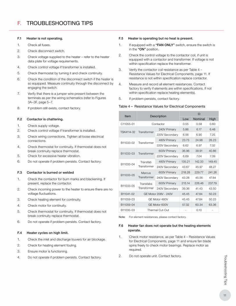
3. Verify the contactor coil resistance as per Table 4 – Resistance Values for Electrical Components, page 11. If resistance is not within specification replace contactor.
4. Measure and record all element resistances. Contact factory to verify if elements are within specifications. If not within specification replace heating element(s).
5. If problem persists, contact factory.
F.6 Heater fan does not operate but the heating elements operate.
1. Check motor resistance, as per Table 4 – Resistance Values for Electrical Components, page 11 and ensure fan blade spins freely to check motor bearings. Replace motor as required.
2. Do not operate unit. Contact factory.
Table 4 – Resistance Values for Electrical Components
Item DescriptionΩ
Low Nominal High
C11055-01 Contactor 0.55 0.58 0.60
TSK4114-32 Transformer 240V Primary 5.86 6.17 6.48
220V Secondary 6.56 6.90 7.25
B11033-02 Transformer 480V Primary 23.73 24.98 26.23
220V Secondary 6.62 6.97 7.32
B11033-03 Transformer 600V Primary 36.96 38.91 40.86
220V Secondary 6.69 7.04 7.39
B11033-04Transfab
Transformer
480V Primary 135.21 142.33 149.45
240V Secondary 43.67 45.97 48.27
B11033-05Marcus
Transformer
600V Primary 218.28 229.77 241.26
240V Secondary 43.28 45.56 47.84
B11033-05Transfabs
Transformer
600V Primary 215.14 226.46 237.79
240V Secondary 39.36 41.43 43.50
B11041-02 GE Motor 208V - 240V 45.45 47.84 50.23
B11059-03 GE Motor 480V 45.45 47.84 50.23
B11059-04 GE Motor 600V 57.32 60.34 63.36
B11035-03 Thermal Cut-Out - 0.10 -
Note: For element resistances, please contact factory.

12
Trou
bles
hoot
ing
Tips
Table 5 – Recommended Torque Specifications
Item Description Inch Pounds
Heating Elementswithout bus bars 16
with bus bars 30
Contactor—
18–22
Mounting Bolt/Nut 65–75 (ft-lbs)
F.7 The Ground Fault Interrupter (GFI) trips on the main panel, or heater blows fuses.
1. Check that you have a fuse of the proper amperage rating.
2. Check for loose or frayed wiring.
3. If condition is not observable, send heater in for repair.
F.8 The fan is turning but very little air comes from the front of the heater.
1. Check fan rotation and ensure fan turns clockwise as seen from the front of the heater. Refer to Section B. Installation, page 4.
2. Check motor winding resistance.
3. Check fan blade set screws to ensure fan blade is not loose on the motor shaft.
4. Do not operate unit. Contact factory.
13
Technical Data
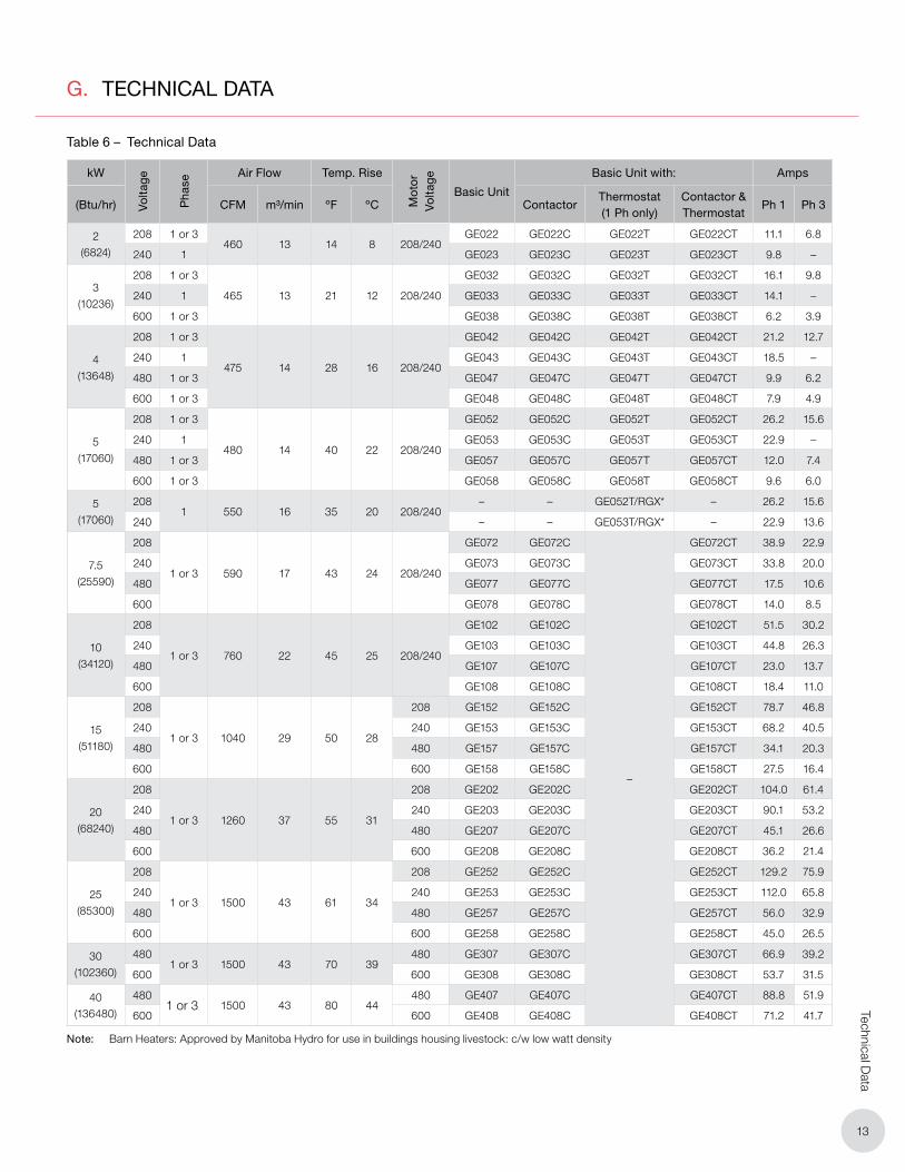
G. TECHNICAL DATA
Table 6 – Technical Data
kW
Vo
ltag
e
Pha
seAir Flow Temp. Rise
Mot
or
Vo
ltag
e
Basic Unit
Basic Unit with: Amps
(Btu/hr) CFM m³/min ºF ºC ContactorThermostat (1 Ph only)
Contactor & Thermostat
Ph 1 Ph 3
2 (6824)
208 1 or 3460 13 14 8 208/240
GE022 GE022C GE022T GE022CT 11.1 6.8
240 1 GE023 GE023C GE023T GE023CT 9.8 –
3 (10236)
208 1 or 3
465 13 21 12 208/240
GE032 GE032C GE032T GE032CT 16.1 9.8
240 1 GE033 GE033C GE033T GE033CT 14.1 –
600 1 or 3 GE038 GE038C GE038T GE038CT 6.2 3.9
4 (13648)
208 1 or 3
475 14 28 16 208/240
GE042 GE042C GE042T GE042CT 21.2 12.7
240 1 GE043 GE043C GE043T GE043CT 18.5 –
480 1 or 3 GE047 GE047C GE047T GE047CT 9.9 6.2
600 1 or 3 GE048 GE048C GE048T GE048CT 7.9 4.9
5 (17060)
208 1 or 3
480 14 40 22 208/240
GE052 GE052C GE052T GE052CT 26.2 15.6
240 1 GE053 GE053C GE053T GE053CT 22.9 –
480 1 or 3 GE057 GE057C GE057T GE057CT 12.0 7.4
600 1 or 3 GE058 GE058C GE058T GE058CT 9.6 6.0
5 (17060)
2081 550 16 35 20 208/240
– – GE052T/RGX* – 26.2 15.6
240 – – GE053T/RGX* – 22.9 13.6
7.5 (25590)
208
1 or 3 590 17 43 24 208/240
GE072 GE072C
–
GE072CT 38.9 22.9
240 GE073 GE073C GE073CT 33.8 20.0
480 GE077 GE077C GE077CT 17.5 10.6
600 GE078 GE078C GE078CT 14.0 8.5
10 (34120)
208
1 or 3 760 22 45 25 208/240
GE102 GE102C GE102CT 51.5 30.2
240 GE103 GE103C GE103CT 44.8 26.3
480 GE107 GE107C GE107CT 23.0 13.7
600 GE108 GE108C GE108CT 18.4 11.0
15 (51180)
208
1 or 3 1040 29 50 28
208 GE152 GE152C GE152CT 78.7 46.8
240 240 GE153 GE153C GE153CT 68.2 40.5
480 480 GE157 GE157C GE157CT 34.1 20.3
600 600 GE158 GE158C GE158CT 27.5 16.4
20 (68240)
208
1 or 3 1260 37 55 31
208 GE202 GE202C GE202CT 104.0 61.4
240 240 GE203 GE203C GE203CT 90.1 53.2
480 480 GE207 GE207C GE207CT 45.1 26.6
600 600 GE208 GE208C GE208CT 36.2 21.4
25 (85300)
208
1 or 3 1500 43 61 34
208 GE252 GE252C GE252CT 129.2 75.9
240 240 GE253 GE253C GE253CT 112.0 65.8
480 480 GE257 GE257C GE257CT 56.0 32.9
600 600 GE258 GE258C GE258CT 45.0 26.5
30 (102360)
4801 or 3 1500 43 70 39
480 GE307 GE307C GE307CT 66.9 39.2
600 600 GE308 GE308C GE308CT 53.7 31.5
40 (136480)
4801 or 3 1500 43 80 44
480 GE407 GE407C GE407CT 88.8 51.9
600 600 GE408 GE408C GE408CT 71.2 41.7
Note: Barn Heaters: Approved by Manitoba Hydro for use in buildings housing livestock: c/w low watt density
14
Gen
eral
Spe
cific
atio
ns
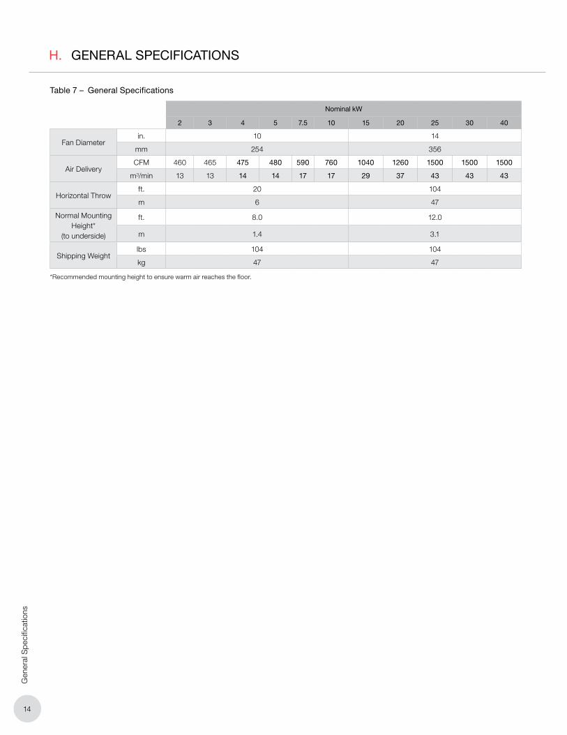
H. GENERAL SPECIFICATIONS
Table 7 – General Specifications
Nominal kW
2 3 4 5 7.5 10 15 20 25 30 40
Fan Diameterin. 10 14
mm 254 356
Air DeliveryCFM 460 465 475 480 590 760 1040 1260 1500 1500 1500
m³/min 13 13 14 14 17 17 29 37 43 43 43
Horizontal Throwft. 20 104
m 6 47
Normal Mounting Height*
(to underside)
ft. 8.0 12.0
m 1.4 3.1
Shipping Weightlbs 104 104
kg 47 47
*Recommended mounting height to ensure warm air reaches the floor.
15
Heater M
aintenance Instructions
I. HEATER MAINTENANCE INSTRUCTIONS
Heater Model
Serial Number
Comments
Date of Maintenance
Maintenance Done By
I.1 Periodic
1. Clean - use compressed air only
� Heating Elements
� Louvers
� Motor
� Inlet Grille
� Fan
2. Mounting & Motor Check
� All mounting hardware condition and tightness
� Motor for smooth, quiet operation
I.2 Annual
1. Electrical Check
� All terminal connections and conductors. Tighten loose connections. Conductors with damaged insulation must be replaced.
� Electrical resistance on all load side legs. Reading should be balanced (± 5%).
WARNING
WARNING. Disconnect heater from power supply at disconnect or fuse box before opening enclosures or servicing heater.
Lock the switch in the “OFF” (open) position and tag the switch to prevent unexpected power application.
This heater should only be serviced by qualified personnel with electrical heating equipment experience.
WARNING
WARNING. Use this heater only as described in this manual. Any other use not recommended by the manufacturer may cause fire, electric shock, or injury to persons.
2. Mechanical Check
� Check heating elements for corrosion and debris buildup. Clean as required.
� Check motor shaft bearing play. Replace motor if play is excessive, or if motor does not run quietly and smoothly. Bearings are permanently lubricated.
� Check fan. Replace immediately if cracked, damaged, or out of balance.
� Check tightness of all hardware. All fasteners must be tight.
� Turn heater on for a minimum of five minutes. Check for warm air exiting heater through louvers.
(before and as required during heating season)
(before heating season)
Oakville
1-800-410-3131
1-905-829-4422
F 905-829-4430
Orillia
1-877-325-3473
1-705-325-3473
F 705-325-2106
WARRANTY: Under normal use the Company warrants to
the purchaser that defects in material or workmanship will be
repaired or replaced without charge for a period of 12 months
from date of shipment. Any claim for warranty must be reported
to the sales office where the product was purchased for autho-
rized repair or replacement within the terms of this warranty.
Subject to State or Provincial law to the contrary, the Company
will not be responsible for any expense for installation, removal
from service, transportation, or damages of any type whatsoever,
including damages arising from lack of use, business interruptions,
or incidental or consequential damages.
The Company cannot anticipate or control the conditions of
product usage and therefore accepts no responsibility for
the safe application and suitability of its products when used
alone or in combination with other products. Tests for the
safe application and suitability of the products are the sole
responsibility of the user.
This warranty will be void if, in the judgment of the Company, the
damage, failure or defect is the result of:
• Vibration, radiation, erosion, corrosion, process con -
tamination, abnormal process conditions, temperature and
pressures, unusual surges or pulsation, fouling, ordinary
wear and tear, lack of maintenance, incorrectly applied
utilities such as voltage, air, gas, water, and others or any
combination of the aforementioned causes not specifically
allowed for in the design conditions, or
• Any act or omission by the Purchaser, its agents, servants
or independent contractors which for greater certainty, but
not so as to limit the generality of the foregoing, includes
physical, chemical or mechanical abuse, accident,
improper installation of the product, improper storage
and handling of the product, improper application or the
misalignment of parts.
No warranty applies to paint finishes except for manufacturing
defects apparent within 30 days from the date of installation.
The Company neither assumes nor authorizes any person to assume for it
any other obligation or liability in connection with the product(s).
The Purchaser agrees that all warranty work required after the initial
commissioning of the product will be provided only if the Company
has been paid by the Purchaser in full accordance with the terms and
conditions of the contract.
The Purchaser agrees that the Company makes no warranty or
guarantee, express, implied or statutory, (including any warranty of
merchantability or warranty of fitness for a particular purpose) written
or oral, of the Article or incidental labour, except as is expressed or
contained in the agreement herein.
LIABILITY: Technical data contained in the catalog or on the
website is subject to change without notice. The Company reserves
the right to make dimensional and other design changes as required.
The Purchaser acknowledges the Company shall not be obligated
to modify those articles manufactured before the formulation of the
changes in design or improvements of the products by the Company.
The Company shall not be liable to compensate or indemnify the
Purchaser, end user or any other party against any actions, claims,
liabilities, injury, loss, loss of use, loss of business, damages, indirect
or consequential damages, demands, penalties, fines, expenses
(including legal expenses), costs, obligations and causes of action of
any kind arising wholly or partly from negligence or omission of the
user or the misuse, incorrect application, unsafe application, incorrect
storage and handling, incorrect installation, lack of maintenance,
improper maintenance or improper operation of products furnished
by the Company.
Edmonton (Head Office)
1-780-466-3178
F 780-468-5904
5918 Roper Road
Alberta, Canada T6B 3E1
Houston
1-855-219-2101
1-281-506-2310
F 281-506-2316
Denver
1-855-244-3128
1-303-979-7339
F 303-979-7350
MC
Chauffage électrique sur demande
For further assistance, please call 24hr hotline: 1.800.661.8529 (U.S.A. and Canada)
Please have model and serial numbers available before calling.
PLEASE ADHERE TO INSTRUCTIONS IN THIS MANUAL
Failure to do so may be dangerous and may void certain provisions
of your warranty.
MC
Chauffage électrique sur demande
Oakville
1-800-410-3131
1-905-829-4422
F 905-829-4430
Orillia
1-877-325-3473
1-705-325-3473
F 705-325-2106
WARRANTY: Under normal use the Company warrants to
the purchaser that defects in material or workmanship will be
repaired or replaced without charge for a period of 12 months
from date of shipment. Any claim for warranty must be reported
to the sales office where the product was purchased for autho-
rized repair or replacement within the terms of this warranty.
Subject to State or Provincial law to the contrary, the Company
will not be responsible for any expense for installation, removal
from service, transportation, or damages of any type whatsoever,
including damages arising from lack of use, business interruptions,
or incidental or consequential damages.
The Company cannot anticipate or control the conditions of
product usage and therefore accepts no responsibility for
the safe application and suitability of its products when used
alone or in combination with other products. Tests for the
safe application and suitability of the products are the sole
responsibility of the user.
This warranty will be void if, in the judgment of the Company, the
damage, failure or defect is the result of:
• Vibration, radiation, erosion, corrosion, process con -
tamination, abnormal process conditions, temperature and
pressures, unusual surges or pulsation, fouling, ordinary
wear and tear, lack of maintenance, incorrectly applied
utilities such as voltage, air, gas, water, and others or any
combination of the aforementioned causes not specifically
allowed for in the design conditions, or
• Any act or omission by the Purchaser, its agents, servants
or independent contractors which for greater certainty, but
not so as to limit the generality of the foregoing, includes
physical, chemical or mechanical abuse, accident,
improper installation of the product, improper storage
and handling of the product, improper application or the
misalignment of parts.
No warranty applies to paint finishes except for manufacturing
defects apparent within 30 days from the date of installation.
The Company neither assumes nor authorizes any person to assume for it
any other obligation or liability in connection with the product(s).
The Purchaser agrees that all warranty work required after the initial
commissioning of the product will be provided only if the Company
has been paid by the Purchaser in full accordance with the terms and
conditions of the contract.
The Purchaser agrees that the Company makes no warranty or
guarantee, express, implied or statutory, (including any warranty of
merchantability or warranty of fitness for a particular purpose) written
or oral, of the Article or incidental labour, except as is expressed or
contained in the agreement herein.
LIABILITY: Technical data contained in the catalog or on the
website is subject to change without notice. The Company reserves
the right to make dimensional and other design changes as required.
The Purchaser acknowledges the Company shall not be obligated
to modify those articles manufactured before the formulation of the
changes in design or improvements of the products by the Company.
The Company shall not be liable to compensate or indemnify the
Purchaser, end user or any other party against any actions, claims,
liabilities, injury, loss, loss of use, loss of business, damages, indirect
or consequential damages, demands, penalties, fines, expenses
(including legal expenses), costs, obligations and causes of action of
any kind arising wholly or partly from negligence or omission of the
user or the misuse, incorrect application, unsafe application, incorrect
storage and handling, incorrect installation, lack of maintenance,
improper maintenance or improper operation of products furnished
by the Company.
Edmonton (Head Office)
1-780-466-3178
F 780-468-5904
5918 Roper Road
Alberta, Canada T6B 3E1
Houston
1-855-219-2101
1-281-506-2310
F 281-506-2316
Denver
1-855-244-3128
1-303-979-7339
F 303-979-7350
ISO 9001
Radiateur GE avec commutateur de débranchement en option
Part No.MI153.Rev.5.02 novembre 2017 Imprimé au Canada
Série GEManuel d’utilisation
Aérothermes à usage régulier
Pour l’installation, l’utilisation, l’entretien, la réparation et les pièces de rechange
C US
®
INSTRUCTIONS IMPORTANTES - CONSERVEZ CES INSTRUCTIONSLisez toutes les consignes avant d’installer ou d’utiliser le chauffage. Veuillez suivre à la lettre toutes les consignes publiées dans ce manuel. Le non-respect des consignes peut être dangereux et peut annuler certaines dispositions de votre garantie.
CaloritechMC est une marque déposée de CCI Thermal Technologies inc.
Droit d’auteur © 2016 Tous droits réservés.
GE 20 3 C T L - D
Série du modèle
Kilowatts02 - 2 kW03 - 3 kW04 - 4 kW05 - 5 kW07 - 7.5 kW10 - 10 kW15 - 15 kW20 - 20 kW25 - 25 kW
30 - 30 kW 40 - 40 kW
Voltage2 - 2083 - 2405 - 3476 - 4167 - 4808 - 600
Contacteur(en option)
Thermostat(en option)
Auteur options
B - Pales de ventilateur et moteur peints
à l’époxy
D - Commutateur de débranchement
F - Commutateur pour le ventilateur
seulement
K - Circuit de commande avec fusible
M - Limite haute pour la réinitialisation
manuelle
N - Relais faible tension (24V)
V - Tension de commande 120 V
(240 est standard)
Code du modèle
Contrôleur de gestion de
l’énergie (en option)

A. Avis importants 19
B. Installation 20
B.1 Emplacement .................................................................................................................20
B.2 Installation ......................................................................................................................20
B.3 Électricité ........................................................................................................................ 21
C. Fonctionnement 24
C.1 Généralités ......................................................................................................................24
D. Réparation et rechange 24
D.1 Éléments chauffants ........................................................................................................24
D.2 Ventilateur .......................................................................................................................24
D.3 Protecteur thermique ......................................................................................................24
E. Liste des pièces de rechange 25
F. Conseils de dépannage 27
F.1 L’aérotherme ne fonctionne pas. ......................................................................................27
F.2 Le contacteur entre en cycle instable. ............................................................................. 27
F.3 Le contacteur est brûlé ou fondu. .................................................................................... 27
F.4 L’aérotherme se met en cycle Arrêt/Marche par la protection de haute température. ...... 27
F.5 L’aérotherme fonctionne, mais il n’y a pas de chauffage. ................................................. 27
F.6 Le ventilateur ne tourne pas, mais les éléments chauffants fonctionnent. ........................27
F.7 Le disjoncteur différentiel de fuite à la terre (DDFT) se déclenche dans le panneau principal, ou l’aérotherme fait sauter les fusibles. ............................................................28
F.8 Le ventilateur tourne, mais le débit d’air à la sortie est très faible. ....................................28
H. Caractéristiques générales 30
TABLE DES MATIÈRES
19
Avis im
portants
A. AVIS IMPORTANTS
ATTENTION
ATTENTION. Ce symbole indique une situation potentiellement dangereuse qui, si elle n’est pas évitée, peut causer des blessures ou des dommages à l’équipement.
AVERTISSEMENT
AVERTISSEMENT. Ce symbole indique une situation de danger imminent qui, si elle n’est pas évitée, peut causer des blessures graves ou des dommages à l’équipement.
AVERTISSEMENT
AVERTISSEMENT. Lisez et respectez les consignes suivantes. Le non-respect de ces consignes risque de provoquer un incendie, une électrocution ou des blessures mortelles. La garantie sera annulée.
1. Lisez et suivez toutes les consignes dans ce manuel.
2. Cet aérotherme est conçu pour le chauffage intérieur des espaces commerciaux et industriels.
AVERTISSEMENT
AVERTISSEMENT. L’aérotherme ne doit pas être utilisé dans des milieux dangereux qui présentent des risques de vapeurs, liquides ou gaz inflammables ou d’autres combustibles.
3. L’aérotherme ne doit être raccordé et entretenu que par un électricien agréé.
4. L’installation et le raccordement de l’aérotherme doivent se conformer à toutes les normes en vigueur.
5. Coupez l’alimentation électrique de l’aérotherme au niveau du boîtier de l’interrupteur ou des fusibles avant de l’ouvrir pour tout entretien. SI L’ON ENTRETIENT LE BOÎTIER DE L’INTERRUPTEUR, assurez-vous que l’alimentation est coupée au niveau des fusibles ou du panneau principal. Bloquez l’interrupteur dans la position « OFF » (circuit ouvert) et marquez l’interrupteur d’un avis de service pour éviter son armement fortuit.
AVERTISSEMENT
AVERTISSEMENT. Les éléments chauffent pendant le fonctionnement. Brûlures en cas de contact.
6. Ne faites pas fonctionner l’aérotherme dans des environnements humides.
7. Respectez les dégagements autour de l’appareil lors de l’installation, suivant ce manuel.
8. Ne faites pas fonctionner l’aérotherme dans des atmosphères corrosives.
9. Utilisez uniquement des pièces de rechange d’origine.
10. La température ambiante maximale de fonctionnement est 40°C (104°F)
11. Ne faites pas fonctionner l’aérotherme avec des déflecteurs déformés ou abimés.
12. Pour toute question ou préoccupation à propos de l’aérotherme, veuillez voir la dernière page de ce manuel pour des renseignements utiles sur les contacts.
13. Suivez les procédures recommandées d’entretien se trouvant à la Section I. Instructions pour l’entretien de l’aérotherme, page 31.

20
Inst
alla
tion
B. INSTALLATION
Respectez toutes les normes en vigueur. Pour une performance optimale, l’aérotherme doit être installé en respectant les directives suivantes:
B.1 Emplacement
1. Assurez-vous que rien n’obstrue l’entrée ni la sortie d’air de l’aérotherme. Référez-vous à la Figure 1 et Figure 2, page 20, pour les dégagements minimaux d’installation.
2. Assurez-vous que l’air de sortie ne souffle pas directement sur un thermostat.
3. Veillez à ce que l’air de sortie ne souffle pas sur une zone susceptible à la perte de chaleur, comme une fenêtre.
4. Vérifiez que l’air de sortie souffle le long des murs extérieurs en formant un angle léger.
5. S’il est important de protéger un équipement contre le gel, dirigez l’air de sortie vers cet équipement tout en respectant les dégagements minimaux.
ATTENTION
ATTENTION. L’installation de tous les modèles d’aérotherme requiert un dégagement d’au moins 152 mm (6 po) du plafond et des murs sur tous les côtés.
B.2 Installation
1. L’aérotherme doit être installé de façon permanente.
2. La base d’installation doit être suffisamment solide pour:
2.1 Supporter le poids de l’aérotherme.
2.2 Offrir une rigidité suffisante afin d’empêcher des vibrations excessives.
3. Le support à boulon unique n’est pas conçu pour des charges dynamiques se manifestant pendant le transport. Pour les aérothermes qui doivent être installés avant le transport, il est recommandé de prévoir un blocage temporaire ou des sangles pour limiter les mouvements de l’aérotherme par rapport à la structure de support. Il est aussi recommandé d’inspecter le couple de serrage du boulon d’installation après le transport pour s’assurer que celui-ci ne s’est pas desserré pendant le transport. Le boulon d’installation et l’écrou doivent être serrés à un couple de 65 à 75 pi-lb. Consultez le Tableau 5 – Spécifications recommandées de couple de serrage, page 28.
4. Installez le support sur l’aérotherme à l’aide du matériel de fixation fourni.
4.1 Positionnez l’aérotherme dans son emplacement final avant de le fixer avec le matériel de fixation.
4.2 Pour les installations qui subissent des vibrations importantes, il est recommandé d’utiliser un frein-filet non permanent du type LoctiteMD 243MC bleu.
Tableau 1 – Dimensions de l’aérotherme et du support éléments chauffants
Dim.210 kW 15 – 40 kW
po mm po mmA 17 432 24 610
B 14 356 19 1/2 495
C (Depth) 15 1/2 394 22 559
R (Hole dia.) 1/2 13 5/8 16
S 12 1/2 318 17 1/2 445
T 4 1/2 114 6 152
U 4 1/2 114 6 152
W (Hole dia.) 3/4 19 3/4 19
Tableau 2 – Hauteur d’installation et poids du radiateur
kWRecommended
Mounting Height - ft (m)
Heater Weightlbs (kg)
2 – 10 6 - 8 (1.8 - 2.4) 59 (24)
15 – 40 8 - 12 (2.4 - 3.0) 104 (47)
Figure 1
Directives générales pour l’installation et le raccordement électrique.
Figure 3 Dégagement d’installation
WALL MOUNTWITH CLEARANCES
FRONT VIEW REAR VIEW
2¼"
B
A
HEATING ELEMENTS
MOTOR
1/2" x 3/4" MULTIPLECONDUIT ENTRY
1" x 1-1/4" MULTIPLECONDUIT ENTRY
6"MIN. INLET
WALL MOUNTBRACKET HOLE
PATTERN
CLEARANCE
6 FT C
MOUNTING ARM
S
T
U
MIN.DISCHARGEDISTANCE
'R' HOLE
CEILING MOUNTWITH CLEARANCES
'W' HOLE
6" MIN.CEILING
CLEARANCE
Éléments chauffants
1/2" x 3/4" Entrée de câblage multiple
1" x 1-1/4" Entrée de câblage multiple
‘W’ trou
WALL MOUNTWITH CLEARANCES
FRONT VIEW REAR VIEW
2¼"
B
A
HEATING ELEMENTS
MOTOR
1/2" x 3/4" MULTIPLECONDUIT ENTRY
1" x 1-1/4" MULTIPLECONDUIT ENTRY
6"MIN. INLET
WALL MOUNTBRACKET HOLE
PATTERN
CLEARANCE
6 FT C
MOUNTING ARM
S
T
U
MIN.DISCHARGEDISTANCE
'R' HOLE
CEILING MOUNTWITH CLEARANCES
'W' HOLE
6" MIN.CEILING
CLEARANCE
‘R’ trou
Disposition des trous de fixation sur
le support mural
WALL MOUNTWITH CLEARANCES
FRONT VIEW REAR VIEW
2¼"
B
A
HEATING ELEMENTS
MOTOR
1/2" x 3/4" MULTIPLECONDUIT ENTRY
1" x 1-1/4" MULTIPLECONDUIT ENTRY
6"MIN. INLET
WALL MOUNTBRACKET HOLE
PATTERN
CLEARANCE
6 FT C
MOUNTING ARM
S
T
U
MIN.DISCHARGEDISTANCE
'R' HOLE
CEILING MOUNTWITH CLEARANCES
'W' HOLE
6" MIN.CEILING
CLEARANCE
6" Distance minimale
du plafond
PLAFOND MURAL AVEC DÉGAGEMENTS
WALL MOUNTWITH CLEARANCES
FRONT VIEW REAR VIEW
2¼"
B
A
HEATING ELEMENTS
MOTOR
1/2" x 3/4" MULTIPLECONDUIT ENTRY
1" x 1-1/4" MULTIPLECONDUIT ENTRY
6"MIN. INLET
WALL MOUNTBRACKET HOLE
PATTERN
CLEARANCE
6 FT C
MOUNTING ARM
S
T
U
MIN.DISCHARGEDISTANCE
'R' HOLE
CEILING MOUNTWITH CLEARANCES
'W' HOLE
6" MIN.CEILING
CLEARANCE
SUPPORT MURAL AVEC DÉGAGEMENTS
Bras de montage
6" Dégagement
minimal à l’entrée
6' Dégagement
minimal à la sortie
Figure 2 – Dégagement d’installation
Moteur
VUE DE FACE VUE ARRIÈRE
B
A
2 1/4"

21
Installation
Figure 3A – Série GE 2 – 10 kW. Schéma de câblage avec option de protection haute température. Modèles de 208 V et 240 V.
4.3 Un serrage adéquat du boulon d’installation impliquera une compression totale de la rondelle de blocage fendue ainsi qu’une inspection du bon entraînement du filetage. Le boulon d’installation et l’écrou doivent être serrés à un couple de 65 à 75 pi-lb. Consultez le Tableau 5 – Spécifications recommandées de couple de serrage, page 28.
5. Les lames du déflecteur de sortie d’air sont orientables individuellement.
B.3 Électricité
AVERTISSEMENT
AVERTISSEMENT. Coupez l’alimentation électrique de l’aérotherme au niveau du boîtier de l’interrupteur ou des fusibles avant de l’ouvrir pour tout entretien.
Bloquez l’interrupteur dans la position « OFF » (circuit ouvert) et marquez l’interrupteur d’un avis de service pour éviter son armement fortuit.
Cet aérotherme doit être entretenu uniquement par des personnes qualifiées ayant une expérience pertinente dans les équipements de chauffage électrique.
Installez et utilisez cet aérotherme conformément aux normes locales en vigueur et aux instructions de ce manuel.
B.3.1 Généralités
1. Utilisez uniquement des fils conducteurs en cuivre pour l’installation. Pour l’épaisseur des fils électriques, consultez la Section G. Données techniques, page 29, ainsi que la plaque signalétique de l’aérotherme.
2. L’alimentation électrique peut être monophasée ou triphasée, suivant les indications de la plaque signalétique. Les schémas de câblage se trouvent sur la face interne du couvercle du boîtier de raccordement (ou consultez la Section B.4 Schémas de câblage typiques – Aérotherme de série GE, page 22 – 23. Volume du boîtier de raccordement: 2–10 kW: 9893 cm³, 15 – 40 kW: 32333 cm³.
B.3.2 Câblage in-situ
1. L’aérotherme vient dans une enceinte pourvue d’ouvertures de dimensions standards pour accommoder les câbles
électriques ou les fils d’un thermostat externe. Deux pastilles défonçables pour conduits de ½ po ou ¾ po se trouvent sur les appareils de 2 – 10 kW. Deux pastilles défonçables pour conduits de ½ po, ¾ po, 1 po ou 1-1/4 po se trouvent sur les appareils de 15 – 40 kW.
2. L’aérotherme peut être livré muni d’un thermostat incorporé. Les aérothermes qui ne sont pas munis d’un thermostat intégré devraient être dotés d’un thermostat à distance. Raccordez le thermostat à distance au bornier prévu (voir Section B.4 Schémas de câblage typiques – Aérotherme de série GE, page 22 – 23. Il est possible de commander des thermostats à distance du fabricant. Un thermostat raccordé à cet aérotherme doit avoir:
2.1 Une approbation UL ou CSA
2.2 Une capacité nominale de 240 V et 5 A.
3. Mise à la terre - une vis de mise à terre avec une rondelle de finition se trouve à côté du bornier. Avant de brancher le courant, assurez-vous que l’aérotherme est correctement mis à la terre.
4. Les modèles qui ne sont pas munis d’un contacteur intégré devraient être dotés d’un interrupteur de sécurité intégré au circuit de commande d’un contacteur externe. Dans le cas d’une alimentation triphasée, le circuit de commande doit être relié à L2 et L3 qui alimentent l’élément chauffant central. Référez-vous à la Figure 3E, page 23. L’interrupteur de sécurité doit avoir des valeurs nominales de 600 V et 10 A résistif.
B.3.3 Inspection finale
1. Avant de brancher le courant électrique:
1.1 Vérifiez que tous les raccordements sont bien faits et qu’ils sont conformes aux exigences des normes en vigueur.
1.2 Vérifiez que la tension de l’alimentation est conforme aux spécifications de la plaque signalétique.
1.3 Retirez de l’aérotherme tout corps étranger.
1.4 Vérifiez que tous les accessoires externes ainsi que les couvercles des boîtiers sont mis en place et fixés.
1.5 Vérifiez que le ventilateur tourne sans aucune restriction.
1.6 Si l’aérotherme en est équipé, vérifiez que le protecteur thermique manuel est réarmé.
CÂBLAGE D’USINE CÂBLAGE IN-SITU
3 Phase 1 Phase
Raccordez au circuit de bobine de l’interrupteur externe.
Interrupteur de sécurité (haute température)
22
Inst
alla
tion
B.4 Schémas de câblage typiques – Aérotherme de série GE
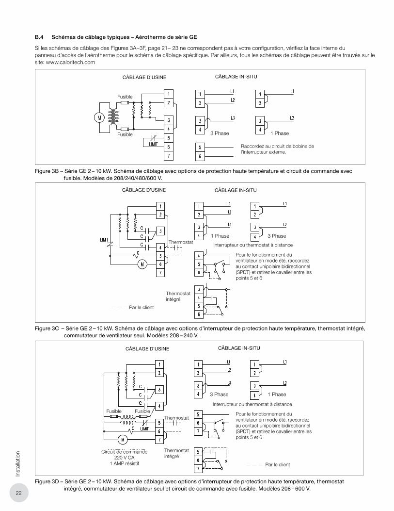
Si les schémas de câblage des Figures 3A – 3F, page 21 – 23 ne correspondent pas à votre configuration, vérifiez la face interne du panneau d'accès de l’aérotherme pour le schéma de câblage spécifique. Par ailleurs, tous les schémas de câblage peuvent être trouvés sur le site: www.caloritech.com
Figure 3B – Série GE 2 – 10 kW. Schéma de câblage avec options de protection haute température et circuit de commande avec fusible. Modèles de 208/240/480/600 V.
Figure 3C – Série GE 2 – 10 kW. Schéma de câblage avec options d’interrupteur de protection haute température, thermostat intégré, commutateur de ventilateur seul. Modèles 208 – 240 V.
Figure 3D – Série GE 2 – 10 kW. Schéma de câblage avec options d’interrupteur de protection haute température, thermostat intégré, commutateur de ventilateur seul et circuit de commande avec fusible. Modèles 208 – 600 V.
CÂBLAGE D’USINE CÂBLAGE IN-SITU
CÂBLAGE D’USINE CÂBLAGE IN-SITU
CÂBLAGE D’USINE CÂBLAGE IN-SITU
Fusible
Fusible
Fusible Fusible
3 Phase 1 Phase
1 Phase 3 Phase
1 Phase3 Phase
Thermostat
Thermostat
Interrupteur ou thermostat à distance
Interrupteur ou thermostat à distance
Pour le fonctionnement du ventilateur en mode été, raccordez au contact unipolaire bidirectionnel (SPDT) et retirez le cavalier entre les points 5 et 6
Pour le fonctionnement du ventilateur en mode été, raccordez au contact unipolaire bidirectionnel (SPDT) et retirez le cavalier entre les points 5 et 6
Thermostat intégré
Thermostat intégré
Par le client
Par le client
Circuit de commande 220 V CA
1 AMP résistif
Raccordez au circuit de bobine de l’interrupteur externe.
23
Installation
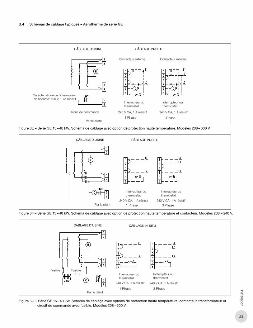
Figure 3E – Série GE 15 – 40 kW. Schéma de câblage avec option de protection haute température. Modèles 208 – 600 V.
Figure 3F – Série GE 15 – 40 kW. Schéma de câblage avec option de protection haute température et contacteur. Modèles 208 – 240 V.
Figure 3G – Série GE 15 – 40 kW. Schéma de câblage avec options de protection haute température, contacteur, transformateur et circuit de commande avec fusible. Modèles 208 – 600 V.
B.4 Schémas de câblage typiques – Aérotherme de série GE
CÂBLAGE D’USINE CÂBLAGE IN-SITU
CÂBLAGE D’USINE CÂBLAGE IN-SITU
CÂBLAGE D’USINE CÂBLAGE IN-SITU
Fusible Fusible
3 Phase1 Phase
3 Phase1 Phase
1 Phase 3 Phase
Interrupteur ou thermostat
Interrupteur ou thermostat
Interrupteur ou thermostat
Interrupteur ou thermostat
Interrupteur ou thermostat
Interrupteur ou thermostat
Par le client
Par le client
Par le client
Caractéristique de l’interrupteur de sécurité: 600 V, 10 A résistif
Circuit de commande
Contacteur externe Contacteur externe
240 V CA, 1 A résistif 240 V CA, 1 A résistif
240 V CA, 1 A résistif 240 V CA, 1 A résistif
240 V CA, 1 A résistif 240 V CA, 1 A résistif

24
Fonc
tionn
emen
t. R
épar
atio
n &
rec
hang
e
C. FONCTIONNEMENT
C.1 Généralités
1. Pour faire fonctionner l’aérotherme, vérifiez que l’alimentation est raccordée comme il faut, selon les spécifications du schéma de câblage (voir Figures 3A – 3F, page 21 – 23).
2. Si l’aérotherme est muni d’un thermostat, veillez à ce que celui-ci soit réglé à une température supérieure à la température ambiante.
3. Si l’aérotherme est muni du commutateur en option « Ventilateur seul (« FAN ONLY »), vérifiez que le commutateur est sur la position « ON ». Remarque : Si le commutateur est sur la position « FAN ONLY », seul le ventilateur fonctionnera, sans les éléments chauffants.
4. Pendant le fonctionnement normal de l’aérotherme, le protecteur thermique ne doit pas s’engager et mettre l’appareil dans un cycle d’arrêt et de marche. Si l’aérotherme se met en cycle d’arrêt/marche, vérifiez si le flux d’air est bloqué. S’il n’y a aucun blocage, il faut qu’une personne qualifiée examine l’aérotherme pour déceler la cause de l’interruption répétée du protecteur thermique.
5. Il faut que l’aérotherme soit en marche au moins pendant 10 minutes avant que les éléments chauffants atteignent une stabilité. Si de l’air chaud ne sort pas de l’aérotherme, arrêtez l’appareil et consultez la section F.1 L’aérotherme ne fonctionne pas., page 27.
D. RÉPARATION ET RECHANGE
AVERTISSEMENT
AVERTISSEMENT. Coupez l’alimentation électrique de l’aérotherme au niveau du boîtier de l’interrupteur ou des fusibles avant de l’ouvrir pour tout entretien.
Bloquez l’interrupteur dans la position « OFF » (circuit ouvert) et marquez l’interrupteur d’un avis de service pour éviter son armement fortuit.
Cet aérotherme doit être entretenu uniquement par des personnes qualifiées ayant une expérience pertinente dans les équipements de chauffage électrique.
Installez et utilisez cet aérotherme conformément aux normes locales en vigueur et aux instructions de ce manuel.
REMARQUE: UTILISEZ UNIQUEMENT DES PIÈCES DE RECHANGE DE SPÉCIFICATIONS IDENTIQUES FOURNIES PAR LE FABRICANT. CONSULTEZ LE TABLEAU 3 – LISTE DES PIÈCES DE RECHANGE: ÉLÉMENT CHAUFFANT, PAGE 26, POUR LA LISTE COMPLÈTE DES PIÈCES DISPONIBLES.
D.1 Éléments chauffants
1. Débranchez tous les fils qui sont raccordés aux bornes des éléments chauffants. Retirez l’ensemble des déflecteurs de l’aérotherme. Retirez les éléments chauffants, prenant note de leur emplacement exact.
2. Installez les éléments chauffants de rechange fournis par le fabricant (voir Figure 4 – Assemblage de l’élément chauffant, page 24).
2.1 Vérifiez que les vis qui servent à fixer les éléments chauffants sont en bon état.
2.2 Remettez et serrez les vis de fixation des éléments chauffants.
2.3 Vérifiez que les éléments chauffants ne se touchent pas et ne touchent pas d’autres parties de l’enceinte.
3. Raccordez tous les fils à l’aide du matériel de fixation fourni. Serrez les vis des bornes au couple spécifié, consultez le Tableau 5 – Spécifications recommandées de couple de serrage, page 28
4. Reposez les déflecteurs.
D.2 Ventilateur
1. Retirez la grille arrière. Retirez la vis fixant le ventilateur à son moyeu rattaché au moteur.
2. Remplacez le ventilateur par celui fourni par le fabricant. Installez le ventilateur de sorte que le « CROISILLON » du ventilateur fait face aux éléments chauffants.
D.3 Protecteur thermique
1. Débranchez tous les fils raccordés au protecteur thermique.
2. Retirez deux vis de fixation.
3. Retirez le protecteur thermique de l’enceinte.
4. Remplacez-le par un nouveau protecteur thermique fourni par le fabricant.
5. Installez le nouveau protecteur thermique dans l’enceinte.
6. Remettez les vis de fixation du protecteur thermique.
7. Raccordez tous les fils au protecteur thermique.
HEATER CABINETPANEL
ELEMENT TERMINALHARDWARE
ELEMENT MOUNTING HARDWARE
HEATING ELEMENT
Figure 4 – Assemblage de l’élément chauffant
Élément chauffant
Plaque de montage de
l’élément chauffant
Matériel de fixation des
bornes de l'élément
Matériel de fixation de
l’élément

25
Liste des pièces de rechange
2
7
3
11
12
10
6
13
4
5
158
1
14
16
9
PARTS LISTITEM DESCRIPTION
1 CABINET BOX ASSEMBLY
2 LOUVER ASSEMBLY
3 MOTOR MOUNT
4 MOTOR
5 FAN BLADE
6 COVER PANEL
7 REAR GRILLE
8 NON-FINNED (2-10 KW), FINNED ELEMENT (15-40 KW)
9 THERMOSTAT - SPST
10 THERMOSTAT KNOB
11 TRANSFORMER
12 THERMAL CUT-OUT
13 TERMINAL BLOCK, 6 POLE
14 TERMINAL BLOCK, 3 POLE
15 CONTACTOR, 3 POLE
16 GROUND CONNECTOR
17 FUSE
17
E. LISTE DES PIÈCES DE RECHANGE
Article Description
1 Enceinte
2 Déflecteurs
3 Support de moteur
4 Moteur
5 Pale de ventilateur
6 Panneau-couvercle
7 Grille arrière
8Éléments chauffants sans ailettes (2–10 kW), et avec ailettes (15–40 kW)
9 Thermostat – unipolaire unidirectionnel
10 Bouton de thermostat
11 Transformateur
12 Protecteur thermique
13 Bornier, 6 bornes
14 Bornier, 3 bornes
15 Contacteur, 3 bornes
16 Connecteur de mise à terre
17 Fusible
Figure 5 – Assemblage de l’élément chauffant
26
List
e de
s pi
èces
de
rech
ange
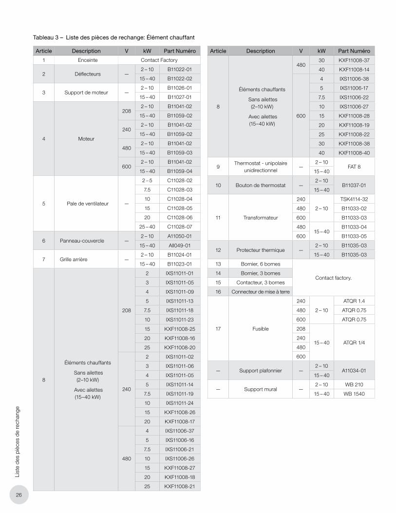
Article Description V kW Part Numéro
1 Enceinte Contact Factory
2 Déflecteurs —2 – 10 B11022-01
15 – 40 B11022-02
3 Support de moteur —2 – 10 B11026-01
15 – 40 B11027-01
4 Moteur
2082 – 10 B11041-02
15 – 40 B11059-02
2402 – 10 B11041-02
15 – 40 B11059-02
4802 – 10 B11041-02
15 – 40 B11059-03
6002 – 10 B11041-02
15 – 40 B11059-04
5 Pale de ventilateur —
2 – 5 C11028-02
7.5 C11028-03
10 C11028-04
15 C11028-05
20 C11028-06
25 – 40 C11028-07
6 Panneau-couvercle —2 – 10 A11050-01
15 – 40 All049-01
7 Grille arrière —2 – 10 B11024-01
15 – 40 B11023-01
8
Éléments chauffants
Sans ailettes (2–10 kW)
Avec ailettes (15–40 kW)
208
2 IXS11011-01
3 IXS11011-05
4 IXS11011-09
5 IXS11011-13
7.5 IXS11011-18
10 IXS11011-23
15 KXF11008-25
20 KXF11008-16
25 KXF11008-20
240
2 IXS11011-02
3 IXS11011-06
4 IXS11011-05
5 IXS11011-14
7.5 IXS11011-19
10 IXS11011-24
15 KXF11008-26
20 KXF11008-17
480
4 IXS11006-37
5 IXS11006-16
7.5 IXS11006-21
10 IXS11006-26
15 KXF11008-27
20 KXF11008-18
25 KXF11008-21
Article Description V kW Part Numéro
8
Éléments chauffants
Sans ailettes (2–10 kW)
Avec ailettes (15–40 kW)
48030 KXF11008-37
40 KXF11008-14
600
4 IXS11006-38
5 IXS11006-17
7.5 IXS11006-22
10 IXS11006-27
15 KXF11008-28
20 KXF11008-19
25 KXF11008-22
30 KXF11008-38
40 KXF11008-40
9Thermostat - unipolaire
unidirectionnel—
2 – 10FAT 8
15 – 40
10 Bouton de thermostat —2 – 10
B11037-0115 – 40
11 Transformateur
240
2 – 10
TSK4114-32
480 B11033-02
600 B11033-03
48015 – 40
B11033-04
600 B11033-05
12 Protecteur thermique —2 – 10 B11035-03
15 – 40 B11035-03
13 Bornier, 6 bornes
Contact factory.14 Bornier, 3 bornes
15 Contacteur, 3 bornes
16 Connecteur de mise à terre
17 Fusible
240
2 – 10
ATQR 1.4
480 ATQR 0.75
600 ATQR 0.75
208
15 – 40 ATQR 1/4240
480
600
— Support plafonnier —2 – 10
A11034-0115 – 40
— Support mural —2 – 10 WB 210
15 – 40 WB 1540
Tableau 3 – Liste des pièces de rechange: Élément chauffant
27
Troubleshooting Tips
F. CONSEILS DE DÉPANNAGE
F.1 L’aérotherme ne fonctionne pas.
1. Vérifiez tous les fusibles.
2. Vérifiez l’interrupteur.
3. Vérifiez la tension d’alimentation de l’aérotherme – consultez la plaque signalétique de l’appareil pour les spécifications électriques.
4. Vérifiez la tension du circuit de commande si un transformateur est installé.
5. Vérifiez le thermostat en l’activant, et vérifiez-en la continuité.
6. Vérifiez l’état de l’interrupteur si l’aérotherme en est équipé. Vérifiez la continuité de l’interrupteur en l’activant.
7. Vérifiez qu’il y a un fil cavalier entre les bornes tel que montré dans le schéma de câblage (voir Figures 3A – 3F, page 21 – 23) .
8. Si le problème persiste, contactez le fabricant.
F.2 Le contacteur entre en cycle instable.
1. Vérifiez la tension de l’alimentation.
2. Vérifiez la tension du circuit de commande si un transformateur est installé.
3. Vérifiez le raccordement des fils. Resserrez toutes les connexions électriques.
4. Vérifiez la continuité du thermostat. Si le thermostat n’arrive pas à rompre la continuité, il faut le remplacer.
5. Vérifiez si l’aérotherme subit des vibrations excessives.
6. Si le problème persiste, ne faites pas fonctionner l’aérotherme. Contactez le fabricant.
F.3 Le contacteur est brûlé ou fondu.
1. Vérifiez le contacteur pour déceler des signes de brûlure ou de noircissement. S’il s’en trouve, remplacez le contacteur.
2. Vérifiez que la tension d’alimentation est stable (pas de fluctuations).
3. Vérifiez la continuité de l’élément chauffant.
4. Vérifiez la continuité du moteur.
5. Vérifiez la continuité du thermostat. Si le thermostat n’arrive pas à rompre la continuité, il faut le remplacer.
6. Si le problème persiste, ne faites pas fonctionner l’aérotherme. Contactez le fabricant.
F.4 L’aérotherme se met en cycle Arrêt/Marche par la protection de haute température.
1. Vérifiez s’il y a un blocage au niveau des déflecteurs d’entrée et de sortie.
2. Vérifiez si l’élément chauffant fonctionne bien.
3. Vérifiez que le moteur fonctionne bien.
4. Si le problème persiste, ne faites pas fonctionner l’aérotherme. Contactez le fabricant.
F.5 L’aérotherme fonctionne, mais il n’y a pas de chauffage.
1. Si l’aérotherme est muni d’un commutateur « Ventilateur seul (« FAN ONLY »), vérifiez que le commutateur est sur la position « ON ».
2. Si l’aérotherme est équipé d’un transformateur et d’un contacteur, vérifiez la tension de commande de la bobine du contacteur. Si la tension ne correspond pas aux spécifications, remplacez le transformateur.
3. Vérifiez la résistance électrique de la bobine du contacteur suivant le Tableau 4 – Résistance des composants électriques, page 27 Si la résistance n’est pas conforme aux spécifications, remplacez le contacteur.
4. Mesurez et enregistrez la résistance de tous les éléments. Consultez le fabricant pour vérifier si les éléments sont conformes aux spécifications. S’ils ne sont pas conformes aux spécifications, remplacez les éléments chauffants.
5. Si le problème persiste, contactez le fabricant.
F.6 Le ventilateur ne tourne pas, mais les éléments chauffants fonctionnent.
1. Vérifiez la résistance du moteur selon le Tableau 4 – Résistance des composants électriques, page 27, et assurez-vous que les pales du ventilateur tournent sans restriction pour vérifier les roulements du moteur. Remplacez le moteur si nécessaire.
2. Ne faites pas fonctionner l’aérotherme. Contactez le fabricant.
Tableau 4 – Résistance des composants électriques
Article DescriptionΩ
Faible Nominale Élevé
C11055-01 Contactor 0.55 0.58 0.60
TSK4114-32 Transformateur240V Primaire 5.86 6.17 6.48
220V Secondaire 6.56 6.90 7.25
B11033-02 Transformateur 480V Primaire 23.73 24.98 26.23
220V Secondaire 6.62 6.97 7.32
B11033-03 Transformateur 600V Primaire 36.96 38.91 40.86
220V Secondaire 6.69 7.04 7.39
B11033-04Transfab
Transformateur
480V Primaire 135.21 142.33 149.45
240V Secondaire 43.67 45.97 48.27
B11033-05Marcus
Transformateur
600V Primaire 218.28 229.77 241.26
240V Secondaire 43.28 45.56 47.84
B11033-05Transfabs
Transformateur
600V Primaire 215.14 226.46 237.79
240V Secondaire 39.36 41.43 43.50
B11041-02 GE Moteur 208V - 240V 45.45 47.84 50.23
B11059-03 GE Moteur 480V 45.45 47.84 50.23
B11059-04 GE Moteur 600V 57.32 60.34 63.36
B11035-03 Protecteur thermique – 0.10 –
Remarque: Pour les valeurs de résistance des éléments, veuillez contacter le
fabricant.
28
Trou
bles
hoot
ing
Tips
F.7 Le disjoncteur différentiel de fuite à la terre (DDFT) se déclenche dans le panneau principal, ou l’aérotherme fait sauter les fusibles.
1. Vérifiez que les fusibles sont adéquats pour l’intensité nominale du courant.
2. Vérifiez que les câbles ne sont pas desserrés ou abimés.
3. S’il est impossible d’établir la cause du problème, renvoyez l’aérotherme pour réparation.
F.8 Le ventilateur tourne, mais le débit d’air à la sortie est très faible.
4. Observez la rotation du ventilateur et veillez à ce qu’il tourne dans le sens des aiguilles d’une montre lorsqu’on fait face à l’aérotherme. Consultez la Section B. Installation, page 20. Vérifiez la résistance des bobines du moteur.
5. Vérifiez la vis de blocage de l’hélice du ventilateur pour qu’elle ne soit pas desserrée sur l’arbre du moteur.
6. Ne faites pas fonctionner l’aérotherme. Contactez le fabricant.
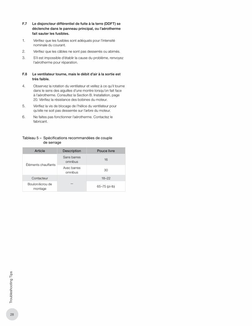
Tableau 5 – Spécifications recommandées de couple de serrage
Article Description Pouce livre
Éléments chauffants
Sans barres omnibus
16
Avec barres omnibus
30
Contacteur
—
18–22
Boulon/écrou de montage
65–75 (pi-lb)

29
Données techniques
G. DONNÉES TECHNIQUES
Tableau 6 – Données techniques
kW
Tens
ion
Pha
seDébit d’air Temp. Hausse
Tens
ion
d
e m
oteu
r
Modèle de base
Modèle de base avec Amp.
(Btu/hr) Pi³/min m³/min ºF ºC ContacteurThermostat
(1 Phase uniquement)
Contacteur et thermostat
Ph 1 Ph 3
2 (6824)
208 1 or 3460 13 14 8 208/240
GE022 GE022C GE022T GE022CT 11.1 6.8
240 1 GE023 GE023C GE023T GE023CT 9.8 –
3 (10236)
208 1 or 3
465 13 21 12 208/240
GE032 GE032C GE032T GE032CT 16.1 9.8
240 1 GE033 GE033C GE033T GE033CT 14.1 –
600 1 or 3 GE038 GE038C GE038T GE038CT 6.2 3.9
4 (13648)
208 1 or 3
475 14 28 16 208/240
GE042 GE042C GE042T GE042CT 21.2 12.7
240 1 GE043 GE043C GE043T GE043CT 18.5 –
480 1 or 3 GE047 GE047C GE047T GE047CT 9.9 6.2
600 1 or 3 GE048 GE048C GE048T GE048CT 7.9 4.9
5 (17060)
208 1 or 3
480 14 40 22 208/240
GE052 GE052C GE052T GE052CT 26.2 15.6
240 1 GE053 GE053C GE053T GE053CT 22.9 –
480 1 or 3 GE057 GE057C GE057T GE057CT 12.0 7.4
600 1 or 3 GE058 GE058C GE058T GE058CT 9.6 6.0
5 (17060)
2081 550 16 35 20 208/240
– – GE052T/RGX* – 26.2 15.6
240 – – GE053T/RGX* – 22.9 13.6
7.5 (25590)
208
1 or 3 590 17 43 24 208/240
GE072 GE072C
–
GE072CT 38.9 22.9
240 GE073 GE073C GE073CT 33.8 20.0
480 GE077 GE077C GE077CT 17.5 10.6
600 GE078 GE078C GE078CT 14.0 8.5
10 (34120)
208
1 or 3 760 22 45 25 208/240
GE102 GE102C GE102CT 51.5 30.2
240 GE103 GE103C GE103CT 44.8 26.3
480 GE107 GE107C GE107CT 23.0 13.7
600 GE108 GE108C GE108CT 18.4 11.0
15 (51180)
208
1 or 3 1040 29 50 28
208 GE152 GE152C GE152CT 78.7 46.8
240 240 GE153 GE153C GE153CT 68.2 40.5
480 480 GE157 GE157C GE157CT 34.1 20.3
600 600 GE158 GE158C GE158CT 27.5 16.4
20 (68240)
208
1 or 3 1260 37 55 31
208 GE202 GE202C GE202CT 104.0 61.4
240 240 GE203 GE203C GE203CT 90.1 53.2
480 480 GE207 GE207C GE207CT 45.1 26.6
600 600 GE208 GE208C GE208CT 36.2 21.4
25 (85300)
208
1 or 3 1500 43 61 34
208 GE252 GE252C GE252CT 129.2 75.9
240 240 GE253 GE253C GE253CT 112.0 65.8
480 480 GE257 GE257C GE257CT 56.0 32.9
600 600 GE258 GE258C GE258CT 45.0 26.5
30 (102360)
4801 or 3 1500 43 70 39
480 GE307 GE307C GE307CT 66.9 39.2
600 600 GE308 GE308C GE308CT 53.7 31.5
40 (136480)
4801 or 3 1500 43 80 44
480 GE407 GE407C GE407CT 88.8 51.9
600 600 GE408 GE408C GE408CT 71.2 41.7
Remarque: Aérothermes agricoles approuvés par Manitoba Hydro pour des bâtiments abritant du bétail : avec des éléments chauffants de faible puissance, une
protection haute température à réinitialisation manuelle, et un thermostat intégré.

30
Car
acté
ristiq
ues
géné
rale
s
H. CARACTÉRISTIQUES GÉNÉRALES
Tableau 7 – Caractéristiques générales
Nominale kW
2 3 4 5 7.5 10 15 20 25 30 40
Diamètre du ventilateur
po 10 14
mm 254 356
Débit d’airpi³/min 460 465 475 480 590 760 1040 1260 1500 1500 1500
m³/h 13 13 14 14 17 17 29 37 43 43 43
Portée horizontalepi 20 104
m 6 47
Hauteur de montage normale
à l’horizontale* (dessous de
l’appareil)
pi 8.0 12.0
m 1.4 3.1
Poids à l’expédition
lbs 104 104
kg 47 47
Remarque: Hauteur de montage recommandée pour assurer que l’air chauffé arrive au plancher.
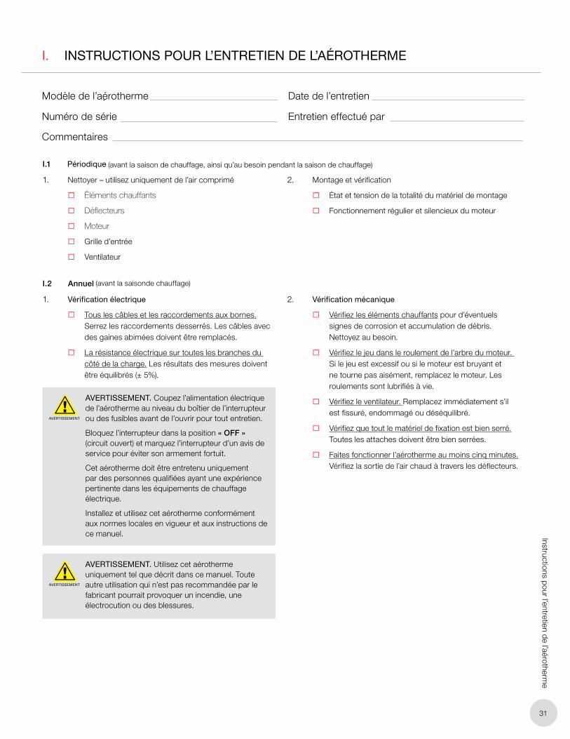
31
Instructions pour l’entretien de l’aérotherme
I. INSTRUCTIONS POUR L’ENTRETIEN DE L’AÉROTHERME
Modèle de l’aérotherme
Numéro de série
Commentaires
Date de l’entretien
Entretien effectué par
I.1 Périodique
1. Nettoyer – utilisez uniquement de l’air comprimé
� Éléments chauffants
� Déflecteurs
� Moteur
� Grille d’entrée
� Ventilateur
2. Montage et vérification
� État et tension de la totalité du matériel de montage
� Fonctionnement régulier et silencieux du moteur
I.2 Annuel
1. Vérification électrique
� Tous les câbles et les raccordements aux bornes. Serrez les raccordements desserrés. Les câbles avec des gaines abimées doivent être remplacés.
� La résistance électrique sur toutes les branches du côté de la charge. Les résultats des mesures doivent être équilibrés (± 5%).
AVERTISSEMENT
AVERTISSEMENT. Coupez l’alimentation électrique de l’aérotherme au niveau du boîtier de l’interrupteur ou des fusibles avant de l’ouvrir pour tout entretien.
Bloquez l’interrupteur dans la position « OFF » (circuit ouvert) et marquez l’interrupteur d’un avis de service pour éviter son armement fortuit.
Cet aérotherme doit être entretenu uniquement par des personnes qualifiées ayant une expérience pertinente dans les équipements de chauffage électrique.
Installez et utilisez cet aérotherme conformément aux normes locales en vigueur et aux instructions de ce manuel.
AVERTISSEMENT
AVERTISSEMENT. Utilisez cet aérotherme uniquement tel que décrit dans ce manuel. Toute autre utilisation qui n’est pas recommandée par le fabricant pourrait provoquer un incendie, une électrocution ou des blessures.
2. Vérification mécanique
� Vérifiez les éléments chauffants pour d’éventuels signes de corrosion et accumulation de débris. Nettoyez au besoin.
� Vérifiez le jeu dans le roulement de l’arbre du moteur. Si le jeu est excessif ou si le moteur est bruyant et ne tourne pas aisément, remplacez le moteur. Les roulements sont lubrifiés à vie.
� Vérifiez le ventilateur. Remplacez immédiatement s’il est fissuré, endommagé ou déséquilibré.
� Vérifiez que tout le matériel de fixation est bien serré. Toutes les attaches doivent être bien serrées.
� Faites fonctionner l’aérotherme au moins cinq minutes. Vérifiez la sortie de l’air chaud à travers les déflecteurs.
(avant la saison de chauffage, ainsi qu’au besoin pendant la saison de chauffage)
(avant la saisonde chauffage)
Oakville
1-800-410-3131
1-905-829-4422
F 905-829-4430
Orillia
1-877-325-3473
1-705-325-3473
F 705-325-2106
GARANTIE: Dans des conditions normales d’utilisation, la
Société garantit à l’acheteur que les produits ayant des défauts
matériels ou de fabrication seront réparés ou remplacés sans
frais pour une période de 12 mois à partir de la date de début de
fonctionnement, selon la date qui arrive à expiration la première.
Toute réclamation dans le cadre de la garantie doit être adressée
à l’agence commerciale dans laquelle le produit a été acheté afin
d’obtenir une réparation ou un remplacement selon les termes de
cette garantie.
Non obstant toute loi fédérale ou provinciale au contraire, la Société
ne pourra être tenue pour responsable des frais encourus pour
l’installation, le retrait du service, le transport ou les dommages de
quelque nature que ce soit, y compris les dommages résultant d’un
manque d’utilisation, d’interruptions d’activité ou de dommages
directs ou indirects.
La Sociéte ne peut anticiper ou contrôler les conditions
d’utilisation du produit et, par conséquent, décline toute
responsabilité quant à l’application et l’adaptation en toute
sécurité de ses produits lors de leur utilisation seuls ou
en combinaison avec d’autres produits. Il est de la seule
responsabilité de l’utilisateur d’effectuer des tests pour vérifier
l’application et l’adaptation en toute sécurité des produits.
Cette garatie sera nulle si, à l’appréciation de la Socitété, le
dommage, la panne ou le défaut a été causé par:
• Des vibrations, des radiations, de l’érosion, de la corrosion,
une contamination du processus, des conditions opératiores
anormales, le températion et la pression, une poussée ou
une pulsation anormale, l’encrassement, une usure normale,
un manque d’entretien, des services appliqués de manière
inappropriée tels que le voltage, l’air, le gaz l’eau et autres, ou
toute autoriées par les conditions de régime; ou
• Tout acte omission de la part de l’Acheteur ses agents,
employés ou entrepreneur indépendant, comprenant pour
une plus grande précision, mais pas au point de limiter
la généralité de ce qui précède, une mauvaise utilisation
physique, chimique ou mécanique, un accident, une
mauvaise installation du produit, de mauvaises conditions
de stockage ou de manipulation du produit, une application
inappropriée ou en défaut d’alignment des pièces.
Aucune garantie ne s’applique à la finition de peinture, excepté dans le
cas de défauts de fabrication apparents dans les 30 jours à compter
de la date d’installation.
Le Société n’assume ni m’autorise auncune personne à assumer en son
nom toute autre obligation ou responsabilité en rapport avec
le/les produit(s).
L’Acheteur accepte que la Société ne fournisse aucune garantie,
expresse, implicite ou légale (y comprise toute garantie de qualité
marchande ou de convenance à des fins particulières), écrite ou
orale, du produit ou de la main-d’oeuvre indirecte, à l’exception des
dispositions exprimées ou contenues dans le présent accord.
RESPONSABILITÉ: Les données techniques contenues dans
le catalogue ou sur le site Web song sujettes à modification sans préavis.
La Société se réserve le droit d’apporter des modifications par rapport
aux dimensions ou à la conception si nécessaire. L’Acheteur reconnaît
que la Société ne sera pas dans l’obligation de modifier ces articles
manufacturés avant la formulation des modifications de conception ou
des améliorations apportées aux produit par la Société
La Société ne sera pas tenue de dédomanger ou d’indemniser
l’Acheteur, l’utilisateur final ou toute autre partie pour les actions, les
réclamations les responsabilités, les préjudices les sinistres, la perte
d’usage, le perte d’activité, les dommages, les dommages indirects ou
consécutifs, les demands, les sanctions, les amendes, les dépanses
(y compris les dépenses légales), les pertes, les obligations et les
conséquences d’une action de quelque nature que ce soit découlant
entièrement ou en partie de la négligence ou de l’omission de l’utilisateur
ou de la mauvise utilisation, de la mauvaise application, de l’utilisation
dangereuse, de mauvaise installation, du manque d’entretien, du
mauvaise entretien ou de la mauvaise opération des produits fournis par
la Société.
Edmonton (Siège social)
1-780-466-3178
F 780-468-5904
5918 Roper Road
Alberta, Canada T6B 3E1
Houston
1-855-219-2101
1-281-506-2310
F 281-506-2316
Denver
1-855-244-3128
1-303-979-7339
F 303-979-7350
MC
Chauffage électrique sur demande Tout manquement à ces dernières pourrait s’avérer dangereux et invalider certaines dispositions de votre garantie.
VEUILLEZ VOUS CONFORMER AUX INSTRUCTIONS CONTENUES DANS CE MANUEL.
Pour obtenir une aide supplémentaire, veuillez appeler: 1-800-661-8529 (U.S.A. and Canada)
Merci de préparervos numéros de modèle et de série avante d’appeler.
Top Related