


Languages
Pages
Legal


Gamma Ray Dectection - An Overview - CAMBERRA 1
Gamma and X-Ray Detection
Detector Overview http://www.canberra.com/default.asp The kinds of detectors commonly used can be categorized as:
• Gas-filled Detectors • Scintillation Detectors • Semiconductor Detectors
The choice of a particular detector type for an application depends upon the X-ray or gamma energy range of interest and the application’s resolution and efficiency requirements. Additional considerations include count rate performance, the suitability of the detector for timing experiments, and of course, price.
Detector Efficiency The efficiency of a detector is a measure of how many pulses occur for a given number of gamma rays. Various kinds of efficiency definitions are in common use for gamma ray detectors: Absolute Efficiency The ratio of the number of counts produced by the detector to the number of gamma rays emitted by the source (in all directions). Intrinsic Efficiency The ratio of the number of pulses produced by the detector to the number of gamma rays striking the detector. Relative Efficiency Efficiency of one detector relative to another; commonly that of a germanium detector relative to a 3 in. diameter by 3 in. long NaI crystal, each at 25 cm from a point source, and specified at 1.33 MeV only. Full-Energy Peak (or Photopeak) Efficiency The efficiency for producing full-energy peak pulses only, rather than a pulse of any size for the gamma ray. Clearly, to be useful, the detector must be capable of absorbing a large fraction of the gamma ray energy. This is accomplished by using a detector of suitable size, or by choosing a detector material of suitable high Z. An example of a full-energy peak efficiency curve for a germanium detector is shown in Figure 1.1 below.
Detector Resolution Resolution is a measure of the width (full width half max) of a single energy peak at a specific energy, either expressed in absolute keV (as with Germanium Detectors), or as a percentage of the energy at that point (Sodium Iodide Detectors). Better (lower) resolution enables the system to more clearly separate the peaks within a spectrum. Figure 1.2 shows two spectra collected from the same source, one using a sodium iodide detector and one using germanium.

Gamma Ray Dectection - An Overview - CAMBERRA 2
Figure 1.1 Efficiency Calibration Even though this is a rather simple spectrum, the peaks presented by the sodium iodide detector are overlapping to some degree, while those from the germanium detector are clearly separated. In a complex spectrum, with peaks numbering in the hundreds, the use of a Germanium detector becomes mandatory for analysis
Figure 1.2 shows two spectra collected from the same source, one using a sodium iodide detector and one using germanium.
Gas-Filled Detectors A gas-filled detector is basically a metal chamber filled with gas and containing a positively biased anode wire. A photon passing through the gas produces free electrons
Gamma Ray Dectection - An Overview - CAMBERRA 3
and positive ions. The electrons are attracted to the anode wire and collected to produce an electric pulse. At low anode voltages, the electrons may recombine with the ions. Recombination may also occur for a high density of ions. At a sufficiently high voltage nearly all electrons are collected, and the detector is known as an ionization chamber. At higher voltages the electrons are accelerated toward the anode at energies high enough to ionize other atoms, thus creating a larger number of electrons. This detector is known as a proportional counter. At higher voltages the electron multiplication is even greater, and the number of electrons collected is independent of the initial ionization. This detector is the Geiger-Müller counter, in which the large output pulse is the same for all photons. At still higher voltages continuous discharge occurs. The different voltage regions are indicated schematically in Figure 1.3. The actual voltages can vary widely from one detector to the next, depending upon the detector geometry and the gas type and pressure.
Scintillation Detectors A gamma ray interacting with a scintillator produces a pulse of light, which is converted to an electric pulse by a photomultiplier tube. The photomultiplier consists of a photocathode, a focusing electrode and 10 or more dynodes that multiply the number of electrons striking them several times each. The anode and dynodes are biased by a chain of resistors typically located in a plug-on tube base assembly. Complete assemblies including scintillator and photomultiplier tube are commercially available from Canberra. The properties of scintillation material required for good detectors are transparency, availability in large size, and large light output proportional to gamma ray energy. Relatively few materials have good properties for detectors. Thallium activated NaI and CsI crystals are commonly used, as well as a wide variety of plastics. NaI is the dominant material for gamma detection because it provides good gamma ray resolution and is economical. However, plastics have much faster pulse light decay and find use in timing applications, even though they often offer little or no energy resolution.
NaI(Tl) Scintillation Detectors The high Z of iodine in NaI gives good efficiency for gamma ray detection. A small amount of Tl is added in order to activate the crystal, so that the designation is usually NaI(Tl) for the crystal. The best resolution achievable ranges from 7.5%-8.5% for the 662 keV gamma ray from 137Cs for 3 in. diameter by 3 in. long crystal, and is slightly worse for smaller and larger sizes. Figure 1.6 shows, respectively, the absorption efficiencies of various thicknesses of NaI crystals, and the transmission coefficient through the most commonly used entrance windows.

Gamma Ray Dectection - An Overview - CAMBERRA 4
The family of curves are derived from NBS circular 583 (1956), Table 37, mass attenuation coefficients for NaI(Tl). Each curve represents the percent absorption (l-attenuation) of a parallel beam of gamma rays normally incident on that thickness NaI(Tl) crystal.
Compiled from NBS Circular 583 and supplement to NBS Circular 583. (Estimated Max. Error ±2%) Many configurations of NaI detectors are commercially available, ranging from crystals for x-ray measurements in which the detector is relatively thin (to optimize resolution at the expense of efficiency at higher energies), to large crystals with multiple phototubes. Crystals built with a well to allow nearly spherical 4p geometry counting of weak samples are also a widely-used configuration. A typical preamplifier and amplifier combination is shown in Figure 1.7.
Figure 1.7: NaI(Tl) Detector Electronics
The light decay time constant in NaI is about 0.25 microseconds, and typical charge sensitive preamplifiers translate this into an output pulse rise time of about 0.5 microseconds. For this reason, NaI detectors are not as well-suited as plastic detectors for fast coincidence measurements, where very short resolving times are required.
Plastic Scintillators Many types of plastic scintillators are commercially available and find applications in fast timing, charged particle or neutron detection, as well as in cases where the rugged

Gamma Ray Dectection - An Overview - CAMBERRA 5
nature of the plastic (compared to NaI), or very large detector sizes, are appropriate. Subnanosecond rise times are achieved with plastic detectors coupled to fast photomultiplier tubes, and these assemblies are ideal for fast timing work. Separate outputs are usually used for timing, with the positive dynode output to a preamplifier and amplifier for energy analysis, and the larger negative anode output to a fast discriminator, as shown in Figure 1.8.
Figure 1.8: Plastic Scintillation Detector Electronics Semiconductor Detectors A semiconductor is a material that can act as an insulator or as a conductor. In electronics the term "solid state" is often used interchangeably with semiconductor, but in the detector field the term can obviously be applied to solid scintillators. Therefore, semiconductor is the preferred term for those detectors which are fabricated from either elemental or compound single crystal materials having a band gap in the range of approximately 1 to 5 eV. The group IV elements Silicon and Germanium are by far the most widely-used semiconductors, although some compound semiconductor materials are finding use in special applications as development work on them continues. Table 1.1 shows some of the key characteristics of various semiconductors as detector materials:
Material Z Band Gap(eV)
Energy/e-h pair (eV)
Si 14 1.12 3.61 Ge 32 0.74 2.98 CdTe 48-
52 1.47 4.43
Hgl2 80-53 2.13 6.5
GaAs 31-33 1.43 5.2
Table 1.1: Element vs. Band Gap Semiconductor detectors have a P-I-N diode structure in which the intrinsic (I) region is created by depletion of charge carriers when a reverse bias is applied across the diode. When photons interact within the depletion region, charge carriers (holes and electrons) are freed and are swept to their respective collecting electrode by the electric field. The

Gamma Ray Dectection - An Overview - CAMBERRA 6
resultant charge is integrated by a charge sensitive preamplifier and converted to a voltage pulse with an amplitude proportional to the original photon energy. Since the depletion depth is inversely proportional to net electrical impurity concentration, and since counting efficiency is also dependent on the purity of the material, large volumes of very pure material are needed to ensure high counting efficiency for high energy photons. Prior to the mid-1970’s the required purity levels of Si and Ge could be achieved only by counter-doping P-type crystals with the N-type impurity, lithium, in a process known as lithium-ion drifting. Although this process is still widely used in the production of Si(Li) X-ray detectors, it is no longer required for germanium detectors since sufficiently pure crystals have been available since 1976. The band gap figures in Table 1.1 signify the temperature sensitivity of the materials and the practical ways in which these materials can be used as detectors. Just as Ge transistors have much lower maximum operating temperatures than Si devices, so do Ge detectors. As a practical matter both Ge and Si photon detectors must be cooled in order to reduce the thermal charge carrier generation (noise) to an acceptable level. This requirement is quite aside from the lithium precipitation problem which made the old Ge(Li), and to some degree Si(Li) detectors, perishable at room temperature. The most common medium for detector cooling is liquid nitrogen, however, recent advances in electrical cooling systems have made electrically refrigerated cryostats a viable alternative for many detector applications. In liquid nitrogen (LN2) cooled detectors, the detector element (and in some cases preamplifier components), are housed in a clean vacuum chamber which is attached to or inserted in a LN2 Dewar. The detector is in thermal contact with the liquid nitrogen which cools it to around 77 °K or –200 °C. At these temperatures, reverse leakage currents are in the range of 10-9 to 10-12 amperes. In electrically refrigerated detectors, both closed-cycle Freon and helium refrigeration systems have been developed to eliminate the need for liquid nitrogen. Besides the obvious advantage of being able to operate where liquid nitrogen is unavailable or supply is uncertain, refrigerated detectors are ideal for applications requiring long-term unattended operation, or applications such as undersea operation, where it is impractical to vent LN2 gas from a conventional cryostat to its surroundings. A cross-sectional view of a typical liquid nitrogen cryostat is shown in Figure 1.9.

Gamma Ray Dectection - An Overview - CAMBERRA 7
Figure 1.9: Model 7500SL Vertical Dipstick Cryostat Detector Structure The first semiconductor photon detectors had a simple planar structure similar to their predecessor, the Silicon Surface Barrier (SSB) detector. Soon the grooved planar Si(Li) detector evolved from attempts to reduce leakage currents and thus improve resolution. The coaxial Ge(Li) detector was developed in order to increase overall detector volume, and thus detection efficiency, while keeping depletion (drift) depths reasonable and minimizing capacitance. Other variations on these structures have come, and some have gone away, but there are several currently in use. These are illustrated in Figure 1.10 with their salient features and approximate energy ranges.
For more information on specific detector types refer to the Detector Products Section
Detector Performance Semiconductor detectors provide greatly improved energy resolution over other types of radiation detectors for many reasons. Fundamentally, the resolution advantage can be attributed to the small amount of energy required to produce a charge carrier and the consequent large "output signal" relative to other detector types for the same incident

Gamma Ray Dectection - An Overview - CAMBERRA 8
photon energy. At 3 eV/e-h pair (see Table 1.1) the number of charge carriers produced in Ge is about one and two orders of magnitude higher than in gas and scintillation detectors respectively. The charge multiplication that takes place in proportional counters and in the electron multipliers associated with scintillation detectors, resulting in large output signals, does nothing to improve the fundamental statistics of charge production. The resultant energy reduction in keV (FWHM) vs. energy for various detector types is illustrated in Table 1.2.
Energy (keV) 5.9 1.22 1.332 Proportional Counter 1.2 ---- ---- X-ray NaI(Tl) 3.0 12.0 ---- 3 x 3 NaI(Tl) ---- 12.0 60 Si(Li) 0.16 ---- ---- Planar Ge 0.18 0.5 ---- Coaxial Ge ---- 0.8 1.8
Table 1.2 Energy Resolution (keV FWHM) vs. Detector Type At low energies, detector efficiency is a function of cross-sectional area and window thickness while at high energies total active detector volume more or less determines counting efficiency. Detectors having thin contacts, e.g. Si(Li), Low-Energy Ge and Reverse Electrode Ge detectors, are usually equipped with a Be cryostat window to take full advantage of their intrinsic energy response. Coaxial Ge detectors are specified in terms of their relative full-energy peak efficiency compared to that of a 3 in. x 3 in. NaI(Tl) Scintillation detector at a detector to source distance of 25 cm. Detectors of greater than 100% relative efficiency have been fabricated from germanium crystals ranging up to about 75 mm in diameter. About two kg of germanium is required for such a detector. Curves of detector efficiency vs. energy for various types of Ge detectors can be found in the Detector Products Section.
Basic Counting Systems -
Pulse Electronics
The nuclear electronics industry has standardized the signal definitions, power supply voltages and physical dimensions of basic nuclear instrumentation modules (NIM). The standardization provides users with the ability to interchange modules, and the flexibility to reconfigure or expand nuclear counting systems, as their counting applications change or grow. Canberra is a leading supplier of Nuclear Instrumentation Modules (NIM). Basic electronic principals, components and configurations which are fundamental in solving common nuclear applications are discussed below.

Gamma Ray Dectection - An Overview - CAMBERRA 9
Preamplifiers and Amplifiers Most detectors can be represented as a capacitor into which a charge is deposited, (as shown in Figure 1.13). By applying detector bias, an electric field is created which causes the charge carriers to migrate and be collected. During the charge collection a small current flows, and the voltage drop across the bias resistor is the pulse voltage.
Figure 1.13: Basic Detector and Amplification The preamplifier is isolated from the high voltage by a capacitor. The rise time of the preamplifier’s output pulse is related to the collection time of the charge, while the decay time of the preamplifier’s output pulse is the RC time constant characteristic of the preamplifier itself. Rise times range from a few nanoseconds to a few microseconds, while decay times are usually set at about 50 microseconds. Charge-sensitive preamplifiers are commonly used for most solid state detectors. In charge-sensitive preamplifiers, an output voltage pulse is produced that is proportional to the input charge. The output voltage is essentially independent of detector capacitance, which is especially important in silicon charged particle detection (i.e. PIPS detectors), since the detector capacitance depends strongly upon the bias voltage. However, noise is also affected by the capacitance. To maximize performance, the preamplifier should be located at the detector to reduce capacitance of the leads, which can degrade the rise time as well as lower the effective signal size. Additionally, the preamplifier also serves to provide a match between the high impedance of the detector and the low impedance of coaxial cables to the amplifier, which may be located at great distances from the preamplifier. The amplifier serves to shape the pulse as well as further amplify it. The long delay time of the preamplifier pulse may not be returned to zero voltage before another pulse occurs, so it is important to shorten it and only preserve the detector information in the pulse rise time. The RC clipping technique can be used in which the pulse is differentiated to remove the slowly varying decay time, and then integrated somewhat to reduce the noise. The unipolar pulse that results is much shorter. The actual circuitry used is an active filter for selected frequencies. A near-Gaussian pulse shape is produced, yielding optimum signal-to-noise characteristics and count rate performance.

Gamma Ray Dectection - An Overview - CAMBERRA 10
A second differentiation produces a bipolar pulse. This bipolar pulse has the advantage of nearly equal amounts of positive and negative area, so that the net voltage is zero. When a bipolar pulse passes from one stage of a circuit to another through a capacitor, no charge is left on the capacitor between pulses. With a unipolar pulse, the charge must leak off through associated resistance, or be reset to zero with a baseline restorer. Typical preamplifier pulses are shown in Figure 1.14.

Gamma Ray Dectection - An Overview - CAMBERRA 11
Figure 1.14: Standard Pulse Waveforms The dashed line in the unipolar pulse indicates undershoot which can occur when, at medium to high count rates, a substantial amount of the amplifier’s output pulses begin to ride on the undershoot of the previous pulse. If left uncorrected, the measured pulse amplitudes for these pulses would be too low, and when added to pulses whose amplitudes are correct, would lead to spectrum broadening of peaks in acquired spectra. To compensate for this effect, pole/zero cancellation quickly returns the pulse to the zero baseline voltage. The bipolar pulse has the further advantage over unipolar in that the zero crossing point is nearly independent of time (relative to the start of the pulse) for a wide range of amplitudes. This is very useful in timing applications such as the ones discussed below. However, the unipolar pulse has lower noise, and constant fraction discriminators have been developed for timing with unipolar pulses. For further discussions on preamplifier and amplifier characteristics, please refer to each applicable module’s subsection. Pulse Height Analysis and Counting Techniques Pulse Height Analysis may consist of a simple discriminator that can be set above noise level and which produces a standard logic pulse (see Figure 1.14) for use in a pulse counter or as gating signal. However, most data consists of a range of pulse heights of which only a small portion is of interest. One can employ either of the following: !"Single Channel Analyzer and Counter !"Multichannel Analyzer !" The single channel analyzer (SCA) has a lower and an upper level discriminator, and produces an output logic pulse whenever an input pulse falls between the discriminator levels. With this device, all voltage pulses in a specific range can be selected and

Gamma Ray Dectection - An Overview - CAMBERRA 12
counted. If additional voltage ranges are of interest, additional SCAs and counters (i.e. scalers) can be added as required, but the expense and complexity of multiple SCAs and counters usually make this configuration impractical. If a full voltage (i.e. energy) spectrum is desired, the SCA’s discriminators can be set to a narrow range (i.e. window) and then stepped through a range of voltages. If the counts are recorded and plotted for each step, an energy spectrum will result. In a typical example of the use of the Model 2030 SCA, the lower level discriminator (LLD) and window can be manually or externally (for instance, by a computer) incremented, and the counts recorded for each step. However, the preferred method of collecting a full energy spectrum is with a multichannel analyzer. The multichannel analyzer (MCA), which can be considered as a series of SCAs with incrementing narrow windows, basically consists of an analog-to-digital converter (ADC), control logic, memory and display. The multichannel analyzer collects pulses in all voltage ranges at once and displays this information in real time, providing a major improvement over SCA spectrum analysis. Figure 1.15 illustrates a typical MCA block diagram. An input energy pulse is checked to see if it is within the selected SCA range, and then passed to the ADC. The ADC converts the pulse to a number proportional to the energy of the event. This number is taken to be the address of a memory location, and one count is added to the contents of that memory location. After collecting data for some period of time, the memory contains a list of numbers corresponding to the number of pulses at each discrete voltage. The display reads the memory contents vs. memory locations, which is equivalent to number of pulses vs. energy.

Gamma Ray Dectection - An Overview - CAMBERRA 13
Figure 1.15. Multichannel Analyzer Components
Counters and Ratemeters Counters and ratemeters are used to record the number of logic pulses, either on an individual basis as in a counter, or as an average count rate as in a ratemeter. Counters and ratemeters are built with very high count rate capabilities so that dead times are minimized. Counters are usually used in combination with a timer (either built-in, or external), so that the number of pulses per unit of time are recorded. Ratemeters feature a built-in timer, so that the count rate per unit of time is automatically displayed. Whereas counters have a LED or LCD for the number of logic pulses, ratemeters have a mechanical meter for real-time display of the count rate. Typically, most counters are designed with 8-decade count capacity and offer an optional external control/output interface, while ratemeters are designed with linear or log count rate scales, recorder outputs and optional alarm level presets/outputs. Additional information may be found in the Counters and Ratemeters Introduction section. Miscellaneous Units Various pulse processing functions have been incorporated into NIM units, such as linear gates, pulse generators, pulse stabilizers, etc. Many of these are described in the following sections and in the introduction to each Nuclear Instrumentation Modules (NIM) Section. Simple Counting Systems As related above, pulse height analysis can consist of a simple single channel analyzer and counter, or a multichannel analyzer. Generally, low resolution/high efficiency

Gamma Ray Dectection - An Overview - CAMBERRA 14
detectors (such as proportional counters and NaI(Tl) detectors) are used in x ray or low-energy gamma ray applications where only a few peaks occur. An example of a simple NaI(Tl) detector-based counting system of this type is illustrated in Figure 1.16.
Figure 1.16: NaI Detector and Counter/Timer with Alarm Ratemeter
In this configuration, a Model 2015A Amplifier/SCA is used to generate a logic pulse for every amplified (detector) pulse that falls within the SCA’s "energy window". The logic pulse is then used as an input to the Model 2071A Counter/Timer which provides the user with a choice of either preset time or preset count operation. The Model 2071A may be equipped with an optional Model 207X-03 EIA Interface, which enables the Model 2071A to be read out to a printer, or controlled and read out to a computer for data storage or further analysis. Alternatively, Model 1481LA Linear/Log Ratemeter is used as the counter, with an alarm relay that will trigger if the count rate exceeds a user preset value. Although counters are still used in some applications, most of today’s counting systems include a multichannel analyzer (MCA). Besides being more cost effective than multiple SCA-based systems, a MCA-based system can provide complete pulse height analysis such that all nuclides, (i.e., even those not expected), can be easily viewed and/or analyzed. NaI(Tl)Detectors and Multichannel Analyzers The need for a single-input Pulse Height Analysis with Sodium Iodide detector is best served by a PC-card MCA, such as the AccuSpec NaI/Plus (Figure 1.17).
Figure 1.17: AccuSpec/NaI Plus MCA Configuration

Gamma Ray Dectection - An Overview - CAMBERRA 15
This single plug-in board includes a High Voltage Power supply, Amplifier, and ADC in addition to its MCA functions, and thus, there is no need for additional modules or a NIM Bin. Further technical discussions concerning multichannel analyzers and multichannel analysis systems (including spectroscopy software) may be found in Multichannel Analyzers and Advanced Spectroscopy Software sections. PIPS Detectors and Multichannel Analyzers Alpha spectroscopy measurements of low-level samples require long counting times. A large area PIPS detector, when configured with a Canberra alpha spectrometer and multichannel analyzer, provides a high resolution, low background, counting system that will satisfy a multitude of alpha spectroscopy applications.
Figure 1.18 Example Large Scale Alpha Spectroscopy System

Gamma Ray Dectection - An Overview - CAMBERRA 16
An example of a single chamber alpha spectroscopy system (that can easily be upgraded) is illustrated in Figure 1.12. Note that the Model 7401 Alpha Spectrometer is a complete, self-contained, 2-wide NIM module that contains a vacuum chamber, vacuum gage, detector bias supply, preamplifier/amplifier, SCA, counter/timer and pulser for setup and test. Multiple Model 7401 Alpha Spectrometers can be configured with a vacuum system that allows individual vacuum chambers to be opened and loaded without affecting the vacuum or data acquisition of the other spectrometers. However, where numerous samples are counted simultaneously, it may be more cost effective and user efficient to select a system based on the Alpha Analyst (Figure 1.18). This turn-key system supports multiple detectors in a comprehensive software environment featuring full computer control of all vacuum elements and acquisition electronics. To learn more about Canberra’s Alpha Analyst, click here. Germanium Detectors and Multichannel Analyzers A typical HPGe detector-based gamma spectroscopy system consists of a HPGe detector, high voltage power supply, preamplifier (which is usually sold as part of the detector), amplifier, analog-to-digital converter and multichannel analyzer. Figure 1.19 illustrates a simple gamma spectroscopy system. This configuration shows NIM electronics for the front end, allowing selection of the optimal spectroscopy amplifier. Canberra offers traditional ‘manually-operated’ NIM modules, as well as a selection of computer-controlled front ends.
Figure 1.19.HPGe Detector and MCA
For higher count rate applications, it is necessary to use an additional circuit to reject pileup pulses that can distort the spectrum. Pileup Rejection/Live Time Correction (PUR/LTC) inspects both the leading edge and the trailing edge of the pulse and can discriminate between two events separated by less than 0.5 microseconds. Since these pileup pulses are rejected, the ADC live time must be lengthened to properly compensate for time the system was unable to process pulses. Virtually all current Canberra ADCs and MCAs (including AccuSpec, InSpector, and AIM) provide signal paths for pulse Pileup Rejection/Live Time Correction as illustrated in Figure 1.20.

Gamma Ray Dectection - An Overview - CAMBERRA 17
Figure 1.20.HPGe Detector with PUR/LTC
LEGe and Si(Li) Detectors with Multichannel Analyzers Low Energy Germanium (LEGe) and Si(Li) detectors require special circuitry to provide the long time constants required in the amplifier to achieve maximum resolution, and to properly handle the pulsed optical feedback signals of their preamplifiers. Although several Canberra amplifiers are suitable, the best resolution will be obtained with the Model 2025 AFT Research Amplifier. Besides allowing the user to select a long shaping time constant, the Model 2025 features an enhanced baseline restorer which is ideal for pulsed optical feedback preamplifiers. In high count rate applications, the long time constants contribute to Pulse Pileup. The Model 2025 contains a built-in Live Time Corrector/Pileup Rejector to prevent these inaccuracies. A typical example of a LEGe or Si(Li) based system is illustrated in Figure 1.21. Note that this system also includes an optional Model 1786A Detector LN2 Monitor to prevent accidental damage to the detector caused by running out of liquid nitrogen.
Figure 1.21. LEGe or Si(Li) Detector and MCA
Multiple Input Systems Traditionally, Mixer/Routers, or Multiplexers, were employed to allow several detectors to be counted in one MCA (with one ADC), as shown in Figure 1.22. Advances in computer technology have dramatically lowered the cost of MCAs and memory, so that, today, it is frequently more effective to use multiple MCAs in place of a Mixer/Router.

Gamma Ray Dectection - An Overview - CAMBERRA 18
The Mixer/Router configuration has a major drawback in that a single ADC processes signals from all detectors, and thus the count rate on the individual detectors must be relatively low to avoid excessive pileup. Additionally, a Mixer/Router must allocate the memory of the MCA among its inputs, which decreases the number of channels available for an individual channel. Within these constraints, Mixer/Routers can be quite efficient for applications such as low-level environmental alpha spectroscopy, in which multiple low-intensity inputs are collected in MCA memory segments of 512 channels or less.
Figure 1.22. Multiple Input System Low Level Gamma Ray Counting Large volume HPGe detectors have become dominant over other detector types for low level gamma ray spectroscopy because of their inherently good resolution and linearity. It is only in the analysis of single radionuclides that NaI(Tl) detectors can compare in sensitivity with HPGe detectors. Since the majority of all gamma spectroscopy applications require the analysis of more complex, multi-radionuclide samples, the following discussion will be limited to the application of HPGe detectors to low level counting. The sensitivity of a HPGe spectrometer system depends on several factors, including detector efficiency, detector resolution, background radiation, sample constituency, sample geometry and counting time. The following paragraphs discuss the role these factors play in low level gamma ray counting. Efficiency Generally, the sensitivity of a HPGe system will be in direct proportion to the detector efficiency. HPGe detectors are almost universally specified for efficiency relative to a 3 in. NaI(Tl) at 25 cm detector-to-source distance at 1.33 MeV, and from this benchmark one may roughly impute the efficiency at lower energies. However, for the customer who is counting weak samples with lower gamma energies, for instance 100-800 keV, the following subtle considerations to the detector design are important to system performance: The detector should have an adequate diameter. This assures that the efficiency at medium and low energies will be high relative to the efficiency at 1.33 MeV, where it is bought and paid for.

Gamma Ray Dectection - An Overview - CAMBERRA 19
The detector-to-end-cap distance should be minimal - five millimeters or less. The inverse square law is real and will affect sensitivity. The detector should be of closed end coaxial geometry, to assure that the entire front face is active. Resolution Generally, the superior resolution of a HPGe detector is sufficient enough to avoid the problem of peak convolution, (i.e., all peaks are separate and distinct). The sensitivity of a system improves as the resolution improves because higher resolution means that spectral line widths are smaller, and fewer background counts are therefore involved in calculating peak integrals. Since the sensitivity is inversely related to the square root of the background, that is, improvements in resolution will not improve sensitivity as dramatically as increased efficiency. Background Radiation and Sample Constituency Interfering background in gamma spectra originates either from within the sample being counted (Compton-produced) or from the environment. If the sample being analyzed has a high content of high-energy gamma emitting radioisotopes, the Compton- produced background will easily outweigh the environmental background. For extremely weak samples, the environmental background becomes more significant. Obviously, massive shielding will do little to improve system sensitivity for low energy gamma rays in the presence of relatively intense higher energy radiation. However, Compton-suppression can be very effective in reducing this background. Sample Geometry An often overlooked aspect of HPGe detector sensitivity is the sample geometry. For a given sample size (and the sample size should be as a large as practicable for maximum sensitivity), the sample should be distributed so as to minimize the distance between the sample volume and the detector itself. This rules out analyzing "test tube" samples with non-well type detectors, or "large area flat samples" with standard detectors. It does rule in favor of using re-entrant or Marinelli-beaker-type sample containers, which distribute part of the sample around the circumference of the detector. Germanium Detectors with Inert Shields There are many different types of shield designs that are available, and because of the difficulty in determining the background contribution of the materials used in a given shield, it is difficult to assign performance levels to various types of shields. However, some criteria for shield designs have evolved over the years, such as:
Gamma Ray Dectection - An Overview - CAMBERRA 20
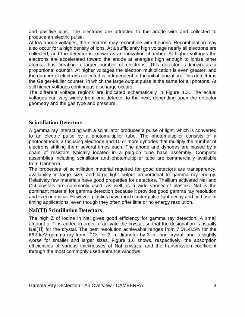
The shield should not be designed to contain unnecessary components like the Dewar. It will only contribute to increased background if it is within the walls of the shield, as well as unnecessarily increase the shield’s size, weight and cost. The detector should be readily installed and removable from the shield. Pity the person who has to move lead bricks (at 12 kg each) to disengage a HPGe detector. A HPGe detector and shield system should have a liquid nitrogen transfer system to avoid removing the detector for the weekly filling. Sample entry should be convenient to the operator. The shield should accommodate a variety of sample sizes and configurations. The HPGe detector should be located in the center of the shield so as to minimize scatter from the walls. In this position, the shield must accommodate the largest sample that is anticipated. Also, sample placement should be accurately repeatable and easily verified by the operator. The shield design that has all these features and is moderately priced is the Canberra Model 747 Lead Shield illustrated in Figures 1.23 and 1.24.
Figure 1.23 Detector located in center of chamber without requirement for extended end-cap

Gamma Ray Dectection - An Overview - CAMBERRA 21
Figure 1.24 Model 747 Lead Shield The performance of the shield using a Canberra HPGe detector is given below: Shield Specs Inside Dimensions 28 cm dia. x 40.5 cm high Wall Thickness 10 cm Material Low Background Lead HPGE Specs Rel. Efficiency 12% Resolution 1.95 keV FWHM at 1.33 MeV 0.90 keV FWHM at 1.22 keV Background Count 2.25 counts/second in the 50 keV-2.7 MeV range The Preamplifier Most Germanium detectors in use today are equipped with RC-feedback, charge sensitive preamplifiers. In the RC-feedback preamplifier, a feedback resistor discharges the integrator, typically in one or two milliseconds. If the incoming energy rate (count rate X energy/count) produces a current that exceeds the capability of the resistor to bleed it off, the output will increase until, in the extreme, the preamplifier saturates and ceases to operate. This limit occurs at approximately 200k MeV/s. The saturated condition remains until the count rate is reduced. The saturation limit is dependent on both energy and count rate and is usually specified in terms of the "energy/rate limit". The energy/rate limit can be increased by lowering the value of the feedback resistor,

Gamma Ray Dectection - An Overview - CAMBERRA 22
but this in turn allows more noise to pass through the preamplifier, resulting in a degradation in resolution. When a Coaxial Germanium detector is used in applications requiring high throughput, the Model 2101 Transistor Reset Preamplifier (TRP) is favored over traditional RC feedback Preamplifiers. The higher cost of the TRP is justified by its much higher energy rate capacity, an enhancement obtained by replacing the Feedback Resistor of a typical RC feedback preamplifier with a special reset circuit. This circuit monitors the dc level of the preamplifier and discharges the feedback capacitor whenever the output reaches a predetermined reset threshold. At moderate to high count rates (i.e. above 20 000 cps), the absence of the feedback resistor and its attendant noise and secondary time constant contributions lead to: The Amplifier The function of the spectroscopy amplifier is to filter the signal for optimum signal to noise ratio and to provide gain, by first differentiating the preamplifier output to provide a rapid return to the baseline reference, and then integrating this signal to capture the energy information. For the best resolution performance, the integration stage produces a Gaussian waveform, and the measure of the width of this pulse may be expressed in terms of its time constant. If the time constant is too short, the amplifier will allow more noise to pass, thus degrading resolution.
Figure 1.28 Resolution vs. Throughput Tradeoffs for a Standard Spectroscopy Amplifier Additionally a short time constant can fail to give enough time for the entire charge collection to take place in the detector (ballistic deficit), which will also affect resolution. On the other hand, a longer time constant lengthens the output pulse of the amplifier (output pulse width is roughly equal to 7.3 x Time Constant) and allows more pileup effects. Since pileup events - one pulse riding on another - carry invalid information, they are typically gated off from the amplifier output. Thus, decreasing the time constant
Gamma Ray Dectection - An Overview - CAMBERRA 23
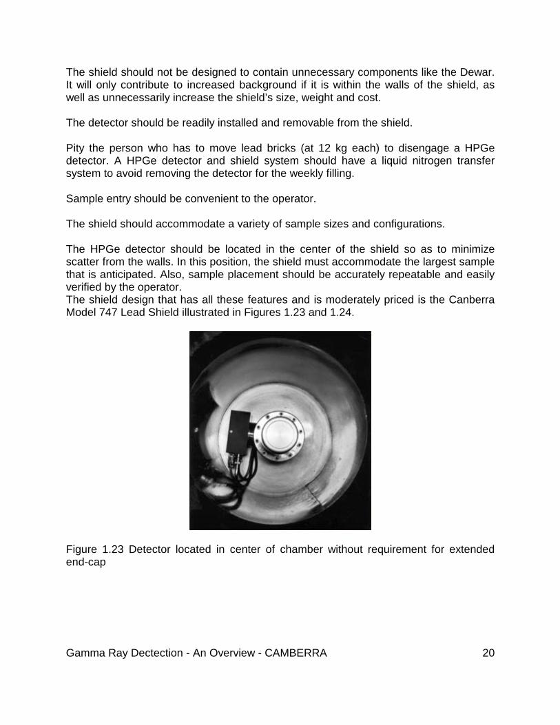
degrades resolution, and increasing it decreases throughput. Figure 1.28 shows the effect of time constant on throughput and resolution: In practice, Coaxial Germanium detectors are usually not operated below 2 ms Gaussian Shaping, and, more typically, at 4 ms shaping to optimize resolution. A technique called Gated Integration (GI) can be used to allow the use of short shaping time constants. The GI Amplifier integrates the entire unipolar signal, providing a properly scaled Linear Output signal with a relatively short time constant, while avoiding the severe impact on resolution that would be seen with a Gaussian pulse of the same width. While the Gated Integrator, with shaping time constants on the order of 0.25 ms, allows higher throughput, it does introduce a certain amount of noise, and thus cannot achieve the same resolution as a standard Gaussian output at, for example, a shaping time of 4 ms. However, this slight and constant degradation in resolution may be a desirable tradeoff in terms of throughput, as evidenced by the plots of count rate and resolution in Figure 1.29.
Figure 1.29 The Gated Integrator vs. a Spectroscopy Amplifier

Gamma Ray Dectection - An Overview - CAMBERRA 24
The ADC Canberra offers two styles of ADC’s - Wilkinson and Fixed Dead Time (FDT). The Wilkinson technique achieves better specifications for differential and integral linearity, and hence resolution, but its throughput is dependent not only on the count rate but by the energy, or converted channel number, of the counts. For spectra with conversion gain of 1024 channels or less, the Wilkinson ADC can outperform most FDT ADC’s available today, with conversion times of typically 5-10 ms. However, at higher conversion gains, the FDT ADC’s will have a decidedly faster conversion time, and thus higher throughput. The Canberra Model 8715 ADC, an FDT ADC with a conversion time of 800 ns, clearly offers the best performance up to its conversion limit of 8K channels. In performance tests, the Model 8715 FDT ADC was found to be so fast that it actually adds NO dead time to spectroscopy systems using traditional Gaussian or triangular shaping amplifiers, and less than 800 nanoseconds to systems using Gated Integrator amplifiers. Summarizing, the combination of the RC Preamplifier, Model 2025 AFT Research Amplifier, and Model 8701 ADC provide optimum resolution at incident counts rates less than 20 000 cps, but the combination of Model 2101 TRP, Model 2024GI Amplifier, and Model 8715 FDT ADC will yield the highest throughput available - up to 70 000 cps, with only a minor tradeoff in resolution, as seen in Figure 1.29. Pulse Pileup Rejection As we saw earlier, pulse pileup occurs when a new pulse from the preamplifier reaches the spectroscopy amplifier before the amplifier has had a chance to finish properly processing the previous pulse. In such cases, an Amplifier/ADC combination with Pile Up Rejection/Live Time Correction (PUR/LTC) has the ability to (a) inhibit the ADC from processing any invalid, composite, pulses, and (b) turn off the Live Time Clock, which is measuring ‘real’ collect time, until the next valid pulse is received at the Amplifier. Typically, this clock is disabled during the time when the Amplifier and ADC are processing a pulse, and thus records the time when the system is ‘ready’ to receive an input pulse. Digital Signal Processor Historically, analog devices have been employed to perform the function of the amplifier in Pulse Height Analysis systems. As noted earlier, this function is not as much amplification as it is processing or shaping. The detector signal is processed, shaped, and filtered by the amplifier and then digitized by the ADC at the end of the processing chain. The selection of the output pulse shape and its associated time constants are designed to maximize the signal-to-noise ratio for optimized resolution and reduced sensitivity to ballistic deficit, while providing the maximum throughput consistent with the resolution requirements of the application. With advances in high speed digital hardware, it is now possible to design and implement digital pulse processors to perform the operations previously only performed by an analog amplifier. With digital

Gamma Ray Dectection - An Overview - CAMBERRA 25
processing, filtering functions can be employed that are not possible with conventional analog signal processing. In Canberra’s Digital Pulse Processing system, the detector/preamplifier signal is digitized much earlier in the signal processing chain. Subsequent processing, filtering, baseline restoration, and pileup rejection are performed digitally, and the results are transferred directly to the MCA histogram memory for viewing and analysis. This system, introduced in 1997, has been shown to provide resolution and throughput performance well in excess of commercially available analog systems, as well as increased precision and repeatability. Loss Free Counting Applications The correction of the Live Time Clock as described above, effectively extending the counting time to account for those periods when the system could not accept an input, is adequate for most samples, in particular those for which the count rate is relatively constant. However, for short Half-Lived samples, or samples whose constituents change (as in a flow monitoring application), this method will not be accurate. In addition, even if the "counts per unit time" are accurate using the traditional method for dead time correction, the "real" counting time will have been extended by an amount equal to the dead time, which may in fact increase the actual collection time to an undesirable length. The principal goal of LFC is to insure that at the end of any data acquisition interval, the electronics have accumulated all of the events that occurred regardless of any dead time that may have been present in the system. LFC is based on the concept that by adding "n" counts per event to an MCA’s channel register, rather than digitizing and storing a single count at a time, a "zero dead time" energy spectrum can be accumulated that assures all counts are included in the spectrum. Assuming that "n" is correctly derived, ("n" should equal "1" plus a "weighting factor" representing the number of events that were lost since the last event was stored), and the data is truly random in nature, the concept is statistically valid. The factor "n" is derived on a continuous basis by examining the state of the Amplifier and ADC every 200 ns. The proportion of time during which the Amplifier and ADC are processing a pulse provides a measure for the magnitude of the weighting factor "n", which is updated every 20 ms. Loss free counting requires that the MCA support "add-n" or multiple "add-one" data transfer; consult the factory for details. Unfortunately, counting statistics in a Loss Free Counting system cannot be calculated from the corrected spectrum. One basic assumption used by all peak fitting algorithms is that of Poisson counting statistics. That is, the uncertainty of the counts is proportional to the square root of the number of counts. While this assumption is true for traditional "add-1" front-ends, it is not true of the "add-n" Loss Free Counting front-end. This assumption is especially poor as the weighting factor becomes large. To properly quantify the uncertainty in each channel’s contents, the peak fitting program must have access to both the corrected "add-n" and the uncorrected "add-1" spectra. Therefore,
Gamma Ray Dectection - An Overview - CAMBERRA 26
Canberra also offers a "Dual-LFC" hardware option for the Model 599 which allows the collection of both of these spectra so that statistically correct peak filling can occur. Note that the correction software for the "Dual-LFC" system is only available for VMS-based Genie Systems.
Top Related