


Languages
Pages
Legal

nualator gas accessoriesEN)g manual
Galaxy® incubator gas accessoriesOperating manual

Copyright © 2014 Eppendorf AG, Germany. No part of this publication may be reproduced without the
prior permission of the copyright owner.
Eppendorf® and the Eppendorf logo are registered trademarks of Eppendorf AG, Germany.
New Brunswick™ is a trademark of Eppendorf AG, Germany.
Galaxy® is a registered trademark of Eppendorf, Inc., USA.
Trademarks are not marked in all cases with ™ or ® in this manual.
6710 900.319-00/112014

3Table of contents
Galaxy incubator gas accessories
English (EN)
Table of contents
1 Safety points . . . . . . . . . . . . . . . . . . . . . . . . . . . . . . . . . . . . . . . . . . . . . . . . . . . . . . . . . . . . . . . . . . . . . . 5
2 Operating instructions . . . . . . . . . . . . . . . . . . . . . . . . . . . . . . . . . . . . . . . . . . . . . . . . . . . . . . . . . . . . . . 72.1 Using this manual . . . . . . . . . . . . . . . . . . . . . . . . . . . . . . . . . . . . . . . . . . . . . . . . . . . . . . . . . . . . . 7
2.2 Danger symbols and danger levels . . . . . . . . . . . . . . . . . . . . . . . . . . . . . . . . . . . . . . . . . . . . . . . . 7
2.2.1 Hazard icons . . . . . . . . . . . . . . . . . . . . . . . . . . . . . . . . . . . . . . . . . . . . . . . . . . . . . . . . . . 7
2.2.2 Degrees of danger. . . . . . . . . . . . . . . . . . . . . . . . . . . . . . . . . . . . . . . . . . . . . . . . . . . . . . 7
2.3 Symbols used . . . . . . . . . . . . . . . . . . . . . . . . . . . . . . . . . . . . . . . . . . . . . . . . . . . . . . . . . . . . . . . . 8
3 Product description . . . . . . . . . . . . . . . . . . . . . . . . . . . . . . . . . . . . . . . . . . . . . . . . . . . . . . . . . . . . . . . . 93.1 Two stage CO2, N2 and O2 regulators. . . . . . . . . . . . . . . . . . . . . . . . . . . . . . . . . . . . . . . . . . . . . . 9
3.1.1 Description . . . . . . . . . . . . . . . . . . . . . . . . . . . . . . . . . . . . . . . . . . . . . . . . . . . . . . . . . . . 9
3.1.2 Features. . . . . . . . . . . . . . . . . . . . . . . . . . . . . . . . . . . . . . . . . . . . . . . . . . . . . . . . . . . . . 10
3.1.3 Model types. . . . . . . . . . . . . . . . . . . . . . . . . . . . . . . . . . . . . . . . . . . . . . . . . . . . . . . . . . 11
3.1.4 Markings . . . . . . . . . . . . . . . . . . . . . . . . . . . . . . . . . . . . . . . . . . . . . . . . . . . . . . . . . . . . 11
3.2 Inline CO2/N2 regulator. . . . . . . . . . . . . . . . . . . . . . . . . . . . . . . . . . . . . . . . . . . . . . . . . . . . . . . . 12
4 Installation . . . . . . . . . . . . . . . . . . . . . . . . . . . . . . . . . . . . . . . . . . . . . . . . . . . . . . . . . . . . . . . . . . . . . . 134.1 Fitting a 2 stage CO2, N2 or O2 regulator to a cylinder . . . . . . . . . . . . . . . . . . . . . . . . . . . . . . . 13
4.2 Fitting an inline CO2/N2 regulator . . . . . . . . . . . . . . . . . . . . . . . . . . . . . . . . . . . . . . . . . . . . . . . 13
5 Operation. . . . . . . . . . . . . . . . . . . . . . . . . . . . . . . . . . . . . . . . . . . . . . . . . . . . . . . . . . . . . . . . . . . . . . . . 151. After fitting of the downstream equipment, open the cylinder valve slowly, this is critical
operation and must be down slowly to be safe.15
6 Technical data . . . . . . . . . . . . . . . . . . . . . . . . . . . . . . . . . . . . . . . . . . . . . . . . . . . . . . . . . . . . . . . . . . . . 176.1 CO2 specifications . . . . . . . . . . . . . . . . . . . . . . . . . . . . . . . . . . . . . . . . . . . . . . . . . . . . . . . . . . . . 17
6.2 N2 specifications . . . . . . . . . . . . . . . . . . . . . . . . . . . . . . . . . . . . . . . . . . . . . . . . . . . . . . . . . . . . . 18
6.3 Inline regulator specifications. . . . . . . . . . . . . . . . . . . . . . . . . . . . . . . . . . . . . . . . . . . . . . . . . . . 19
6.3.1 Typical performance characteristics . . . . . . . . . . . . . . . . . . . . . . . . . . . . . . . . . . . . . . . 22
6.4 Disposal. . . . . . . . . . . . . . . . . . . . . . . . . . . . . . . . . . . . . . . . . . . . . . . . . . . . . . . . . . . . . . . . . . . . 23

Table of contentsGalaxy incubator gas accessories
English (EN)4

5Safety points
Galaxy incubator gas accessories
English (EN)
1 Safety points
Carefully inspect the regulator for oil, grease and damaged or dirty parts. Oxygen vigorously supports
combustion; never use the regulator if oil, grease or damaged parts are detected.
Never:
• Use a regulator showing any kinds of damage
• Allow cylinders to become heated
• Use pressure gauges that are damaged, not smooth in operation or not zeroing
• Remove or change any parts of the regulator
Always:
• Check the whole system for damage and leaks at frequent intervals
• Work to international and local codes of practice
These products are intended for use in industrial compressed air systems only. Do not use these products
where pressures and temperatures can exceed those listed (see CO2 specifications on p. 17). Before using
these products with fluids other than those specified, for non-industrial applications, lifesupport systems,
or other applications not within published specifications, consult Eppendorf. Through misuse, age, or
malfunction, components used in fluid power systems can fail in various modes. The system designer is
warned to consider the failure modes of all component parts used in fluid power systems and to provide
adequate safeguards to prevent personal injury or damage to equipment in the event of such failure.
System designers must provide a warning to end users in the system instructional manual if protection
against a failure mode cannot be adequately provided. System designers and end users are cautioned to
review specific warnings found in instruction sheets packed and shipped with these products.
Water vapor will pass through these units and will condense into liquid if air temperature drops in the
downstream system. Install an air dryer if water condensation could have a detrimental effect on the
application.

Safety pointsGalaxy incubator gas accessories
English (EN)6

7Operating instructions
Galaxy incubator gas accessories
English (EN)
2 Operating instructions2.1 Using this manual
Carefully read this operating manual before using the device for the first time.
The operating manual should be considered as part of the product and stored in a location that is easily
accessible.
When passing the device on to third parties, be sure to include this operating manual.
If this manual is lost, please request another one. The latest version can be found on our website
www.eppendorf.com (international) or www.eppendorfna.com (North America).
2.2 Danger symbols and danger levels
2.2.1 Hazard icons
2.2.2 Degrees of danger
The following danger levels are used in safety messages throughout this manual.
This equipment operates at a maximum altitude of 2000 m.
Biohazard Explosion
UV radiation Toxic substances
Electric shock Crushing
Hot surface Hazard point
Heavy loads Material damage
DANGER Will lead to severe injuries or death.
WARNING May lead to severe injuries or death.
CAUTION May lead to light to moderate injuries.
NOTICE May lead to material damage.
Operating instructionsGalaxy incubator gas accessories
English (EN)8
2.3 Symbols used
Example Meaning
You are requested to perform an action.
1.
2.
Perform these actions in the sequence described.
• List.
References useful information.

9Product description
Galaxy incubator gas accessories
English (EN)
3 Product description3.1 Two stage CO2, N2 and O2 regulators
Only experienced and properly trained persons should handle compressed gases, they should be
conversant with the relevant safety instructions including the current international and local codes of
practice and the gas safety instructions from the gas supplier. Attention is drawn to regulations governing
the use of Acetylene. If in doubt, users should seek guidance from HM Inspectorate of Explosives.
3.1.1 Description
The Bar Multi-stage regulator provides the ultimate answer to industrial gas pressure requirements.
Capable of working on cylinder pressure up to 300 bar, these regulators provide extra safety and precision
control to the user. The two stage reduction of cylinder pressure within the multi-stage regulator combines
extra safety with precise control over the complete pressure range.
The multi-stage regulator is extremely versatile and can be found in many industries serving a wide range
of applications. These include 24 hour life support systems, food and drink processing, laboratory supply
systems, high tech manufacturing control and numerous other industrial applications.
The regulator is produced under our quality management system BS EN ISO 2503.
The range is suitable for all standard industrial gases, including oxygen, acetylene, hydrogen, nitrogen,
argon, helium etc.

Product descriptionGalaxy incubator gas accessories
English (EN)10
3.1.2 Features
Feature Description
Types • Available in 2 gauge form to give total accuracy
and flexibility to suit all welding, cutting, heating
and gas control applications
• The 2 gauge form features both cylinder
contents pressure and the regulated outlet
pressure
Inlet configuration • Available with bottom or side entry inlet
connections to ensure that the regulator fits both
safely and conveniently on all available cylinders
NEVOC • With gas manufacturers throughout Europe
filling cylinders to higher pressures, the need for
standardization of cylinder connections has
necessitated the adoption of a new cylinder
connections
• The New European Valve Outlet Connection
(NEVOC) has been designated to meet these
requirements and has been adopted throughout
Europe for cylinders filled above 250 bar
• Cylinders filled up to and including 250 bar will
continue to use relevant national standards (i.e.
BS 341 connections in the UK)
Safety pressure gauges • Meeting the requirements of the latest standard
BS EN 562, these gauges are the safest possible
design
• All gauges have the gas service indicated and
are marked for maximum working pressure
High flow safety valve • Tamper-proof, this high capacity valve will safely
vent excess pressure and reseal, thus extending
the life of the regulator
Captive pressure adjusting knob • This important feature is designed into the
Gas-Arc range, making it impossible to remove
the adjusting knob
300 bar valve • Using the latest technology available, Gas-Arc
have designed the 300 Bar valves compatible
with high pressure indistrial gases
Inlet filter • All regulators are fitted with an integral inlet
filter that encapsulates the main valve and is
designed to prevent ingress of foreign particles
into the regulator
First stage piston • Solid brass piston to withstand the demands of
300 bar service and provide an accurate and
constant supply to the second stage

11Product description
Galaxy incubator gas accessories
English (EN)
3.1.3 Model types
3.1.4 Markings
The regulator is marked with:
• Maximum inlet pressure (pressure service)
• Rated outlet pressure
• Gas (only use the gas shown)
Second stage diaphragm (unperforated) • This design means the efficiency of the
diaphragm is greatly improved and also reduces
the possibility of leaks, improving safety
Body • The regulator body is manufactured in our fully
automated UK manufacturing facility, from brass
bar stock sourced from reliable and consistent
mills from within the EU
Bonnet • High strength alloy bonnet is designed to safely
contain the increased cylinder pressures
• An ABS shroud is fitted over the bonnet to allow
for the permanent markings of manufacturers
name, maximum inlet pressure, and the product
standard in accordance with the requirements of
BS EN ISO 2503
Flashback arrestors • It is recommended that flashback arrestors are
fitted in all cases when used with oxygen or fuel
gases
Two stage N2 regulatorAll model types with oxygen option
(P0628-7220)
Two stage CO2 regulatorAll model types
(P0628-5010)
Two stage O2regulator
All model types with 1 – 95 % o2 option
(P0628-7222)
Feature Description
Product descriptionGalaxy incubator gas accessories
English (EN)12
3.2 Inline CO2/N2 regulator
Abb. 3-1: Inline CO2/N2 regulator
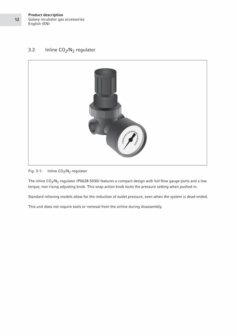
Fig. 3-1: Inline CO2/N2 regulator
The inline CO2/N2 regulator (P0628-5030) features a compact design with full-flow gauge ports and a low
torque, non-rising adjusting knob. This snap action knob locks the pressure setting when pushed in.
Standard relieving models allow for the reduction of outlet pressure, even when the system is dead-ended.
This unit does not require tools or removal from the airline during disassembly.

13Installation
Galaxy incubator gas accessories
English (EN)
4 Installation4.1 Fitting a 2 stage CO2, N2 or O2 regulator to a cylinder
Before fitting the regulator, ensure the cylinder outlet valve and the regulator inlet are clean and free from
contaminants including dirt, oil and water.
If fitted, fully release the regulator adjusting knob by winding anti-clockwise prior to fitting to cylinder.
Right hand thread is employed for oxygen and permanent gases, and left hand thread is used for fuel gases.
Use only the correct size of spanner and finally tighten by applying 2 blows to the end of the spanner with
the heel of the hand.
4.2 Fitting an inline CO2/N2 regulator
The inline regulator can be attached to your Galaxy 170 incubator using the two screws provided in the
pack.
Abb. 4-1: Installing to an incubator
Fig. 4-1: Installing to an incubator
1. Turn off gas supply.
2. Cut PVC tubing to incubator.
3. Connect each end of the tubing to the inlet connectors on the regulator.
Take note of the direction of the flow (located behind the gauge).
4. Fit the supplied cable clips.
5. Turn on the gas supply.
6. Pull the knob.
7. Gradually turn the knob clockwise until the desired pressure is achieved.
5 psi – 7 psi (0.35 - 0.5 bar) in Galaxy CO2 incubators and New Brunswick™ S41i.

InstallationGalaxy incubator gas accessories
English (EN)14

15Operation
Galaxy incubator gas accessories
English (EN)
5 Operation
1. After fitting of the downstream equipment, open the cylinder valve slowly, this is critical operation and
must be down slowly to be safe.
2. If fitted, adjust the regulator knob to the required outlet pressure and purge hoses, making the final
adjustments when the gas is flowing.
3. Check for leaks at all joints with the leak detection spray.
4. On completion of use, close cylinder valve and exhaust gas from lines.
5. If fitted, fully release regulator pressure adjusting knob.
It is vital to ensure that any audible vibration or freezing of the regulator is avoided during
operation.

OperationGalaxy incubator gas accessories
English (EN)16

17Technical data
Galaxy incubator gas accessories
English (EN)
6 Technical data6.1 CO2 specifications
Description Multi-stage cylinder regulator CO2, 0 – 4bar side
entry
Extended Description Gas cylinder regulator grade 4.8, 99.998% purity.
For use with CO2
Max. Inlet Pressure 300 bar (4350 psi)
Operating Pressure 0 – 4 bar (0 – 58 psi)
Effective Orifice Size 3.175 mm (0.125 in)
Inlet Connection BS 341 No.8 R/H
Outlet Connection 3/8 in BSPP coned male c/w hose tail to suit 6.4 mm
(1/4 in) ID hose
Auxiliary Connection
Mounting Style In-line
Wetted Materials Brass, Neoprene
Non-wetted Material Brass, ABS, MAZAK
Media Temperature -20 – 60 °C (-4 – 140 °F)
Ambient Temperature -20 – 60 °C (-4 – 140 °F)
Recommended Filtration 30 micron
Weight 1.95 kg (4.30 lb)
CE Mark No
ROHS Compliant No
REACH Compliant Yes
ATEX Compliant No
WEEE Compliant No
Other approvals
Clean Room Manufactured Controlled Environment
Commodity Code 84682000
Country of Origin UK
Any other Technical Data This regulator incorporates:
• A tamper proof high flow safety valve
• An integral inlet filter that encapsulates the main
valve
• Safety pressure gauges that meet the
requirements of the latest standard BS EN 562

Technical dataGalaxy incubator gas accessories
English (EN)18
6.2 N2 specifications
Description Multi-stage cylinder regulator nitrogen/air 0 – 4 bar
base entry
Extended Description Gas cylinder regulator grade 4.8, 99.998 % purity.
For use with nontoxic/ non-flammable compressed
gases.
Max. Inlet Pressure 300 bar (4350 psi)
Operating Pressure 0 – 4 bar (0 – 58 psi)
Effective Orifice Size 3.175 mm (0.125 in)
Inlet Connection BS 341 No.8 R/H
Outlet Connection 3/8 in BSPP coned male c/w hose tail to suit 6.4 mm
(1/4 in) ID hose
Mounting Style In-line
Wetted Materials Brass, Neoprene
Non-wetted Material Brass, ABS, MAZAK
Media Temperature -20 – 60 °C (-4 – 140 °F)
Ambient Temperature -20 – 60 °C (-4 – 140 °F)
Recommended Filtration 30 micron
Weight 1.95 kg (4.30 lb)
CE Mark No
ROHS Compliant No
REACH Compliant Yes
ATEX Compliant No
WEEE Compliant No
Other approvals
Clean Room Manufactured Controlled Environment
Commodity Code 84682000
Country of Origin UK
Any other Technical Data This regulator incorporates:
• A tamper proof high flow safety valve
• An integral inlet filter that encapsulates the main
valve
• Safety pressure gauges that meet the
requirements of the latest standard BS EN 562

19Technical data
Galaxy incubator gas accessories
English (EN)
6.3 Inline regulator specifications
Fluid Compressed air
Maximum pressure 300 psig (20 bar)
Operating temperature -20 °C – 65 °C (0 °F – 150 °F)
Note: Air supply must be dry enough to avoid ice formation at
temperatures below +2 °C (+35 °C)
Typical flow at 10 bar (150 psig) inlet pressure, 6.3 bar (90 psig) set pressure, and a droop of 1 bar (15 psig) from set
1/8 in ports 6.5 dm3/s (14 scfm)
1/4 in ports 7 dm3/s (15 scfm)
Gauge ports 1/8 in PTF with PTF main ports
1/8 in ISO Rc with ISO Rc main ports
1/8 in ISO Rc with ISO G main ports
Materials Body Zinc
Bonnet Acetal
Valve Brass/nitrile
Valve seat Acetal
Elastomers Nitrile
Bracket mounting Use 3 mm (1/8 in) screws to mount bracket to wall
Dimensions Panel mounting hole
diameter
30 mm (1.19 in)
Maximum panel thickness 0 mm – 6 mm (0 in – 0.25 in)
Technical dataGalaxy incubator gas accessories
English (EN)20
Abb. 6-1: Dimensions
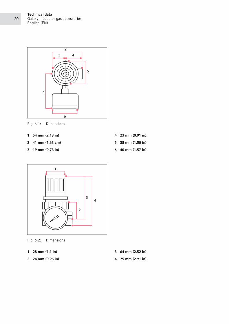
Fig. 6-1: Dimensions
Abb. 6-2: Dimensions
Fig. 6-2: Dimensions
1 54 mm (2.13 in)
2 41 mm (1.63 cm)
3 19 mm (0.73 in)
4 23 mm (0.91 in)
5 38 mm (1.50 in)
6 40 mm (1.57 in)
1 28 mm (1.1 in)
2 24 mm (0.95 in)
3 64 mm (2.52 in)
4 75 mm (2.91 in)
6
43
2
1
5
43
2
1

21Technical data
Galaxy incubator gas accessories
English (EN)
Abb. 6-3: Bracket mounting
Fig. 6-3: Bracket mounting
1 63 mm (2.47 in) 2 28 mm – 44 mm (1.09 in – 1.73 in)
1
2

Technical dataGalaxy incubator gas accessories
English (EN)22
Abb. 6-4: Bracket mounting
Fig. 6-4: Bracket mounting
6.3.1 Typical performance characteristics
1 34 mm (1.34 in)
2 38 mm (1.50 in)
3 24 mm (0.93 in)
4 7 mm (0.29 in)
5 6 mm (0.22 in)
6 42 mm (1.65 in)
Port size: 1/4 in
Inlet pressure: 150 psig (10 bar g)
Range: 5 –psig – 100 psig (0.3 bar – 7 bar)
2
4
3
1
5
6

6.4 Disposal
In case the product is to be disposed of, the relevant legal regulations are to be observed.
Information on the disposal of electrical and electronic devices in the European Community:
Within the European Community, the disposal of electrical devices is regulated by national regulations
based on EU Directive 2012/19/EU pertaining to waste electrical and electronic equipment (WEEE).
According to these regulations, any devices supplied after August 13, 2005, in the business-to-business
sphere, to which this product is assigned, may no longer be disposed of in municipal or domestic waste. To
document this, they have been marked with the following identification:
Because disposal regulations may differ from one country to another within the EU, please contact your
supplier if necessary.
In Germany, this is mandatory from March 23, 2006. From this date, the manufacturer has to offer a
suitable method of return for all devices supplied after August 13, 2005. For all devices supplied before
August 13, 2005, the last user is responsible for the correct disposal.
psig
bar
g
OU
TLE
T P
RE
SSU
RE
FLOW CHARACTERISTICS
100
80
60
40
20
0 0
2
4
6
8
0 2 4 6 8 10
0 4 128 16 20 24AIR FLOW
dm 3/s
scfm

Evaluate Your Manual
Give us your feedback.
www.eppendorf.com/manualfeedback
Your local distributor: www.eppendorf.com/contactEppendorf AG · 22331 Hamburg · Germany
[email protected] · www.eppendorf.com

25Technical data
Galaxy incubator gas accessories
English (EN)

Technical dataGalaxy incubator gas accessories
English (EN)26
Top Related