


Languages
Pages
Legal


G. De Temmerman ITPA 10 meeting, Moscow, April 06 1
Influence of material choice on the Influence of material choice on the deposition/erosion mechanisms deposition/erosion mechanisms affecting optical reflectivity of affecting optical reflectivity of
metallic mirrorsmetallic mirrors
G. De Temmermana, V.S. Voitsenyab, R.A. Pittsc M. Maurera, L. Marota, and P. Oelhafena
a Institute of Physics, University of Basel, Switzerland;
b Institute of Plasma Physics, NSC KIPT, Akademischa St. 1, 61108 Kharkhov, Ukraine;
c Centre de Recherches en Physique des Plasmas, Association EURATOM, Conférédation Suisse, EPFL, 1015 Lausanne, Switzerland

G. De Temmerman ITPA 10 meeting, Moscow, April 06 2
IntroductionIntroduction
• Experiment in Tore Supra with plasma facing mirrors showed strong differences in the sputtering yields of Mo, SS and Cu under similar exposure conditions
• Surface of the SS mirrors appeared to have been protected from sputtering
• A difference in the stickiness of carbon has been proposed to explain these findings (V. Voitsenya, ITPA-9)
• Experiment was initiated in the Univ. Basel to clear up the behaviour of SS and Cu mirrors submitted to D2 glow discharge with controlled partial pressure of methane.
• In parallel, tests of different candidate materials were made in TCV where samples are exposed in the divertor region
• Differences in the deposition efficiency of carbon on different substrates were noticed
G. De Temmerman ITPA 10 meeting, Moscow, April 06 3
U= -200 V
Water cooled sample holder
=0 / 1.8 / 3.5 %
Laboratory experiments (Uni Basel)Laboratory experiments (Uni Basel)
4CHf
In situ measurement of the reflectivity using laser reflectometry (532 nm)
Weight measurement: determination of the eroded/deposited depth
SEM: surface morphology
Total and diffuse reflectivity (250-2500 nm); Spectroscopic ellipsometry (350-2300 nm)
• Exposure of metallic mirrors to a low temperature deuterium plasma with controlled partial pressures of methane in the gas mixture
• 2 substrate materials: copper and stainless steel prepared in IPP Kharkov, Ukraine
Samples characterization:

G. De Temmerman ITPA 10 meeting, Moscow, April 06 4
0.0 0.5 1.0 1.5 2.0
0.0
0.2
0.4
0.6
0.8
1.0
R n
orm
aliz
ed
Fluence (x1019 cm-2)
D2 pure
fCH4
=1.8%
fCH4=3.5%
=532 nm
Strong correlation between the carbon content in the plasma and the degradation rate of R
All samples are "carbon free"
For =3.5%, appearance of interferences typical from the growth of a:CH layer
No carbon on the other samples (EDX measurements)
4CHf
Reflectivity during plasma exposureReflectivity during plasma exposureStainless steel Copper

G. De Temmerman ITPA 10 meeting, Moscow, April 06 5
Evolution of the surface morphologyEvolution of the surface morphologyStainless steel Copper
No significant effect of physical sputtering
Carbon protection effect
Deterioration of the reflectivity by an increase of the roughness
Appearance of the crystallographic grains
%04CHf %0
4CHf
nmRa 4 nmRa 7
%8.14CHf%8.1
4CHf
nmRa 6 nmRa 26
%5.34CHf %5.3
4CHfnmRa 70
G. De Temmerman ITPA 10 meeting, Moscow, April 06 6
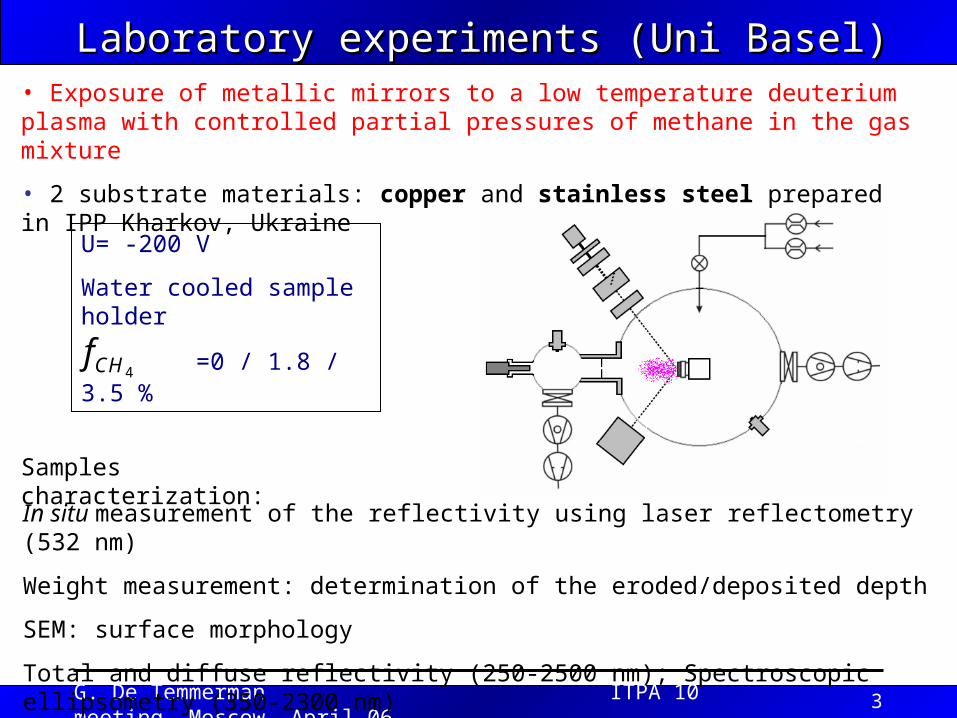
Erosion/deposition measurementsErosion/deposition measurements
• Eroded/ deposited depth estimated both from mass loss measurements and profilometry
Different behaviour of both substrates towards erosion/deposition
0 1 2 3 4-600
-400
-200
0
200
400
Deposition
Stainless steel Copper
Surf
ace
thic
knes
s ch
ange
(nm
)
fCH4
(%)
Erosion

G. De Temmerman ITPA 10 meeting, Moscow, April 06 7
Reflectivity after exposureReflectivity after exposure
500 1000 1500 2000 25000
10
20
30
40
50
60
70
80
90
100
Sp
ecu
lar
refl
ecti
vity
(%
)Wavelength (nm)
Virgin mirror Pure D2 fCH4=1.8%
fCH4=3.5%
Copper Specular reflectivity
500 1000 1500 2000 2500
0
10
20
30
40
50
60
70
80
90
Sp
ecu
lar
refl
ecti
vity
(%
)
Wavelength (nm)
Virgin mirror Pure D2 fCH4
=1.8%
fCH4=3.5%
Stainless steelSpecular reflectivity
• Reflectivity measured with a UV-Vis-NIR spectrophotometer equipped with an integrating sphere
Degradation of the reflectivity due to absorption of light in the deposited layer
Degradation of the reflectivity due to an increase of the surface roughness
Stainless steel
Copper
G. De Temmerman ITPA 10 meeting, Moscow, April 06 8
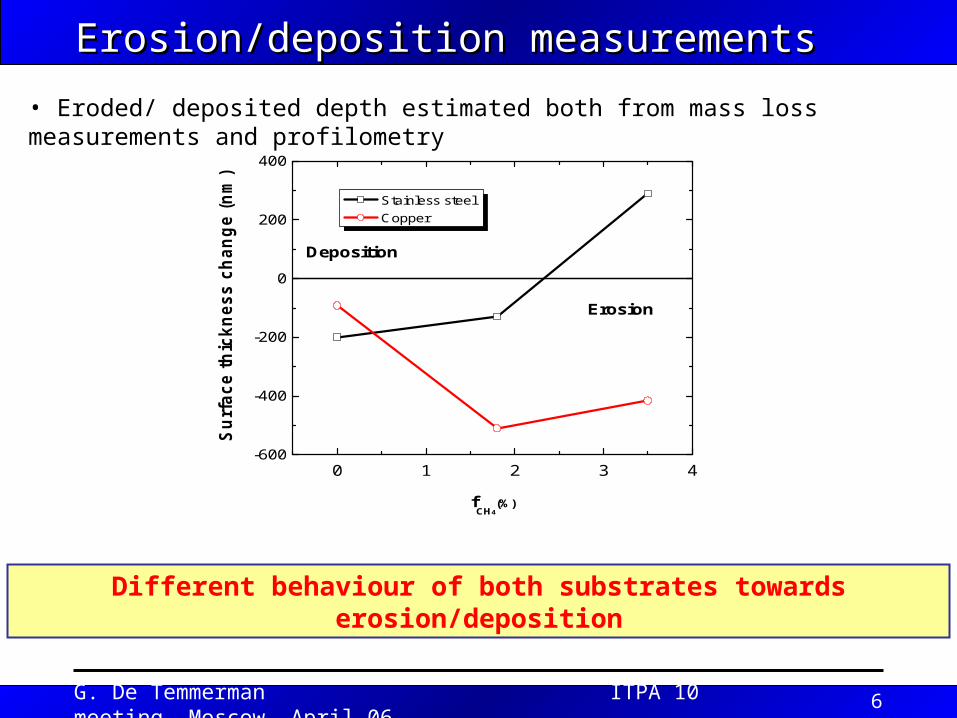
Reflectivity of linearly polarized lightReflectivity of linearly polarized light• Measurement of the reflectivity of linearly polarized light using a spectroscopic elipsometer at various incidence angles.
• Rs: E field perpendicular to the plane of incidence
• Rp: E field parallel to the place of incidence
• Wavelength range: 350-2300 nm
G. De Temmerman ITPA 10 meeting, Moscow, April 06 9
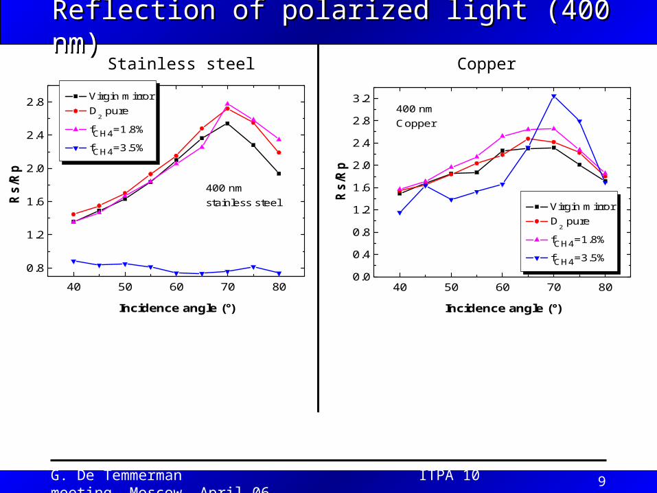
40 50 60 70 80
0.8
1.2
1.6
2.0
2.4
2.8 Virgin mirror D
2 pure
fCH4=1.8%
fCH4=3.5%
Rs/
Rp
Incidence angle (°)
400 nm stainless steel
40 50 60 70 800.0
0.4
0.8
1.2
1.6
2.0
2.4
2.8
3.2
Rs/
Rp
Incidence angle (°)
Virgin mirror D
2 pure
fCH4=1.8%
fCH4=3.5%
400 nm Copper
Reflection of polarized light (400 nm)Reflection of polarized light (400 nm)Stainless steel Copper
G. De Temmerman ITPA 10 meeting, Moscow, April 06 10
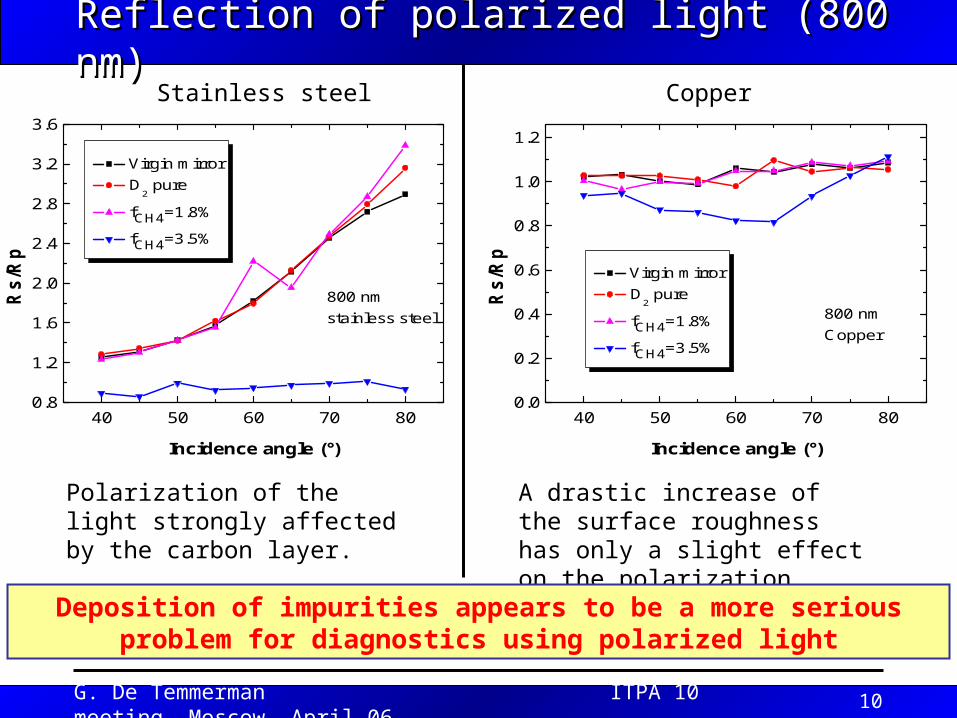
40 50 60 70 800.0
0.2
0.4
0.6
0.8
1.0
1.2
Virgin mirror D
2 pure
fCH4=1.8%
fCH4=3.5%
Rs/R
p
Incidence angle (°)
800 nm Copper
40 50 60 70 800.8
1.2
1.6
2.0
2.4
2.8
3.2
3.6
Virgin mirror D
2 pure
fCH4=1.8%
fCH4=3.5%
Rs/
Rp
Incidence angle (°)
800 nm stainless steel
Reflection of polarized light (800 nm)Reflection of polarized light (800 nm)Stainless steel Copper
Polarization of the light strongly affected by the carbon layer.
A drastic increase of the surface roughness has only a slight effect on the polarization
Deposition of impurities appears to be a more serious problem for diagnostics using polarized light
G. De Temmerman ITPA 10 meeting, Moscow, April 06 11
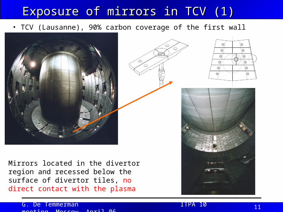
Exposure of mirrors in TCV (1) Exposure of mirrors in TCV (1) • TCV (Lausanne), 90% carbon coverage of the first wall
Mirrors located in the divertor region and recessed below the surface of divertor tiles, no direct contact with the plasma
G. De Temmerman ITPA 10 meeting, Moscow, April 06 12
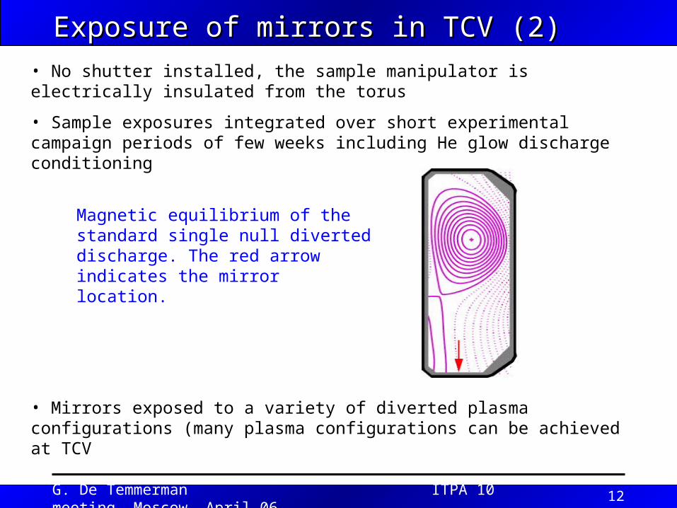
• No shutter installed, the sample manipulator is electrically insulated from the torus
• Sample exposures integrated over short experimental campaign periods of few weeks including He glow discharge conditioning
Magnetic equilibrium of the standard single null diverted discharge. The red arrow indicates the mirror location.
Exposure of mirrors in TCV (2)Exposure of mirrors in TCV (2)
• Mirrors exposed to a variety of diverted plasma configurations (many plasma configurations can be achieved at TCV
G. De Temmerman ITPA 10 meeting, Moscow, April 06 13
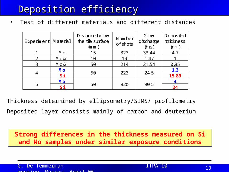
Deposition efficiency Deposition efficiency
Experiment Material Distance below the tile surface
(mm)
Number of shots
Glow discharge
(hrs)
Deposited thickness
(nm)1 Mo 15 323 33.44 4.72 Mo/W 10 19 1.47 13 Mo/W 50 214 21.54 0.85
Mo 1.3Si 15.89Mo 4Si 24
4
5
50
50
223 24.5
820 90.5
• Test of different materials and different distances
Strong differences in the thickness measured on Si and Mo samples under similar exposure conditions
Thickness determined by ellipsometry/SIMS/ profilometry
Deposited layer consists mainly of carbon and deuterium

G. De Temmerman ITPA 10 meeting, Moscow, April 06 14
Summary/ ConclusionsSummary/ Conclusions
• Both laboratory experiments and sample exposures in the TCV tokamak have shown the material dependence of the erosion/deposition patterns affecting the reflectivity of metallic mirrors (with carbon as impurity)
• Monte Carlo simulation (SDTRIMSP) have confirmed the differences observed for the various substrates (not shown here)
• These different features are only of importance until a certain deposited thickness is reached (after this the deposition rate on the various metals is the same)
• Further experiments are needed to test other materials
The material choice not only influences the resistance of mirrors towards erosion but also their sensitivity to impurity deposition
Top Related