


![Fuzzy Logic Direct Torque Control for Asynchronous Motor...Fuzzy logic has been proved to be powerful in the motor control area, e.g., in the PI and [6] Fuzzy Logic Controllers (FLC)](https://static.fdocuments.in/doc/165x107/5f6eca7f1a2ba4328d743464/fuzzy-logic-direct-torque-control-for-asynchronous-motor-fuzzy-logic-has-been.jpg)


Languages
Pages
Legal

Fuzzy Logic Controller Base on Fuzzy Logic Controller Base on Direct Torque ControlDirect Torque Control
Fuzzy Logic Controller Base on Fuzzy Logic Controller Base on Direct Torque ControlDirect Torque Control
Pedro Ponce* Juan C. Ramírez **
*Departamento de Ingeniería Eléctrica, Instituto Tecnológico de
Estudios Superiores de Monterrey.** Section of Graduate Studies and Research , College of Electrical
and Mechanical EngineeringNational Polytechnic Institute
T
T
s
T
i
Selection
TableINVERTER
INDUCTIONMOTOR
i
v
s
v
*
dtRIV ssss
sin2
3ss IPT
sd
sqs tan
1
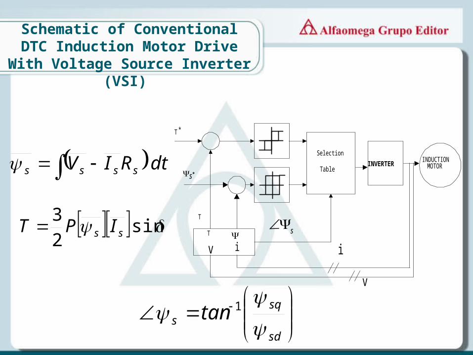
Schematic of Conventional DTC Induction Motor Drive With Voltage
Source Inverter (VSI)
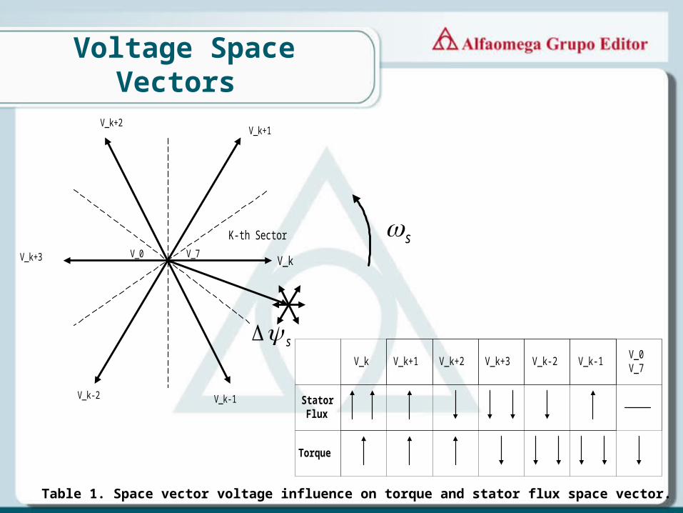
Voltage Space Vectors
V_k
V_k+1V_k+2
V_k+3
V_k-2 V_k-1
s
s
V_0
K-th Sector
V_7
StatorFlux
Torque
V_k V_k+1 V_k+2 V_k+3 V_k-2 V_k-1V_0V_7
Table 1. Space vector voltage influence on torque and stator flux space vector.
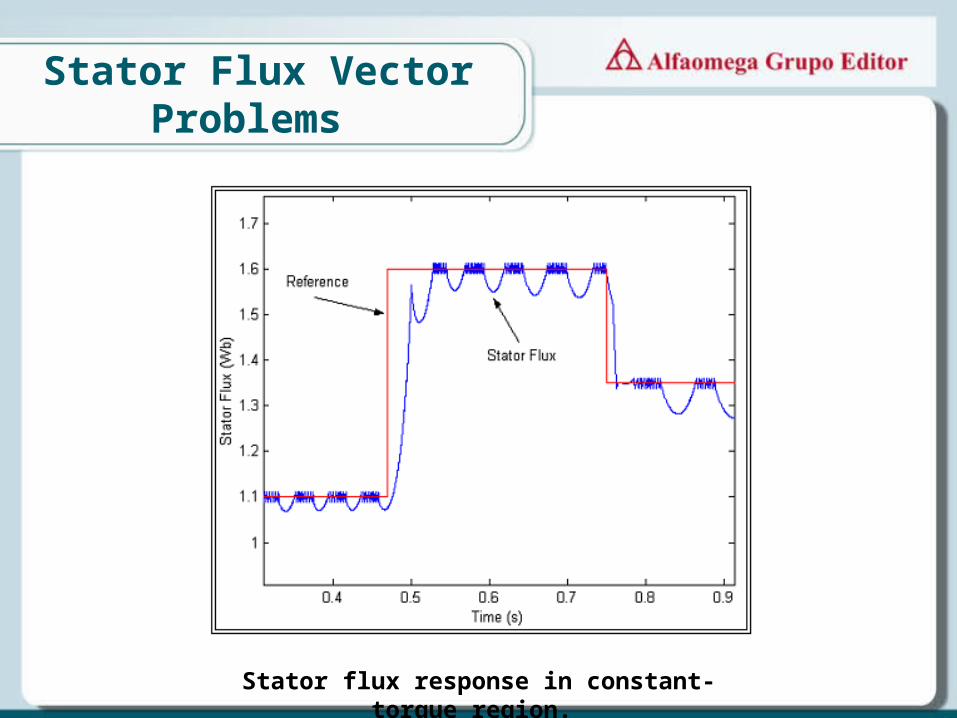
Stator Flux Vector Problems
Stator flux response in constant-torque region.
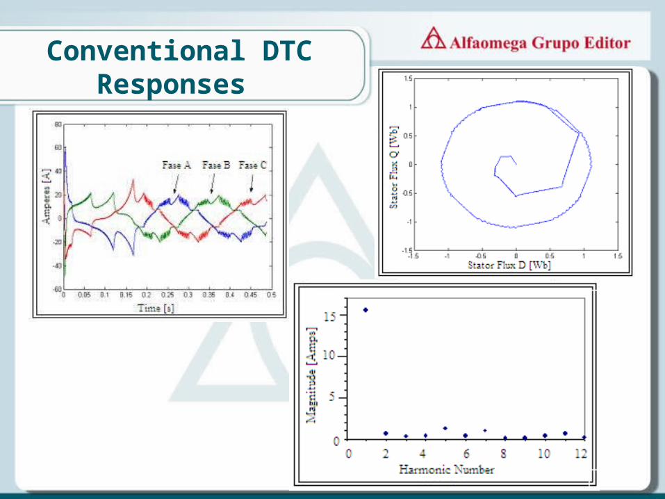
Conventional DTC Responses
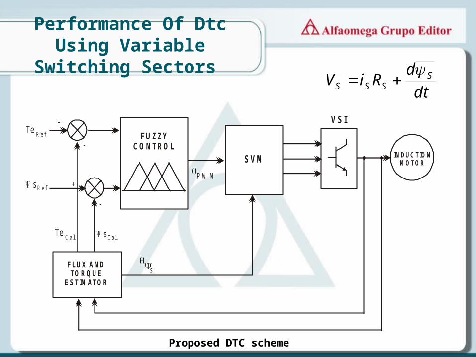
Performance Of Dtc Using Variable Switching Sectors
VSI
INDUCTIONMOTOR
M O D E LO D E LA D IN A M IC A D E L
M O TO R D E IN D U C C IO N
S
Te sCal. Cal.
Te
s
Ref.
Ref.
FLUX ANDTORQUE
ESTIMATOR
SVM
+
+
-
-
P W M
FUZ ZY CO NTROL
dt
dRiV SSSS
Proposed DTC scheme

• The space vector model of induction motor in rotating reference framework, can be describe
SkS
SSS jdt
dRiV
SS
The stator voltage components (Vsx-Vsy) are given by :
dt
dV
S
SX
SkSY jV
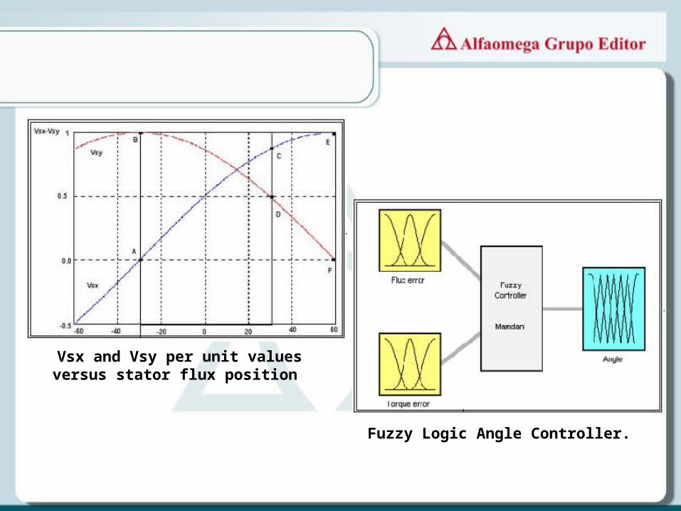
Vsx and Vsy per unit values versus stator flux position
Fuzzy Logic Angle Controller.
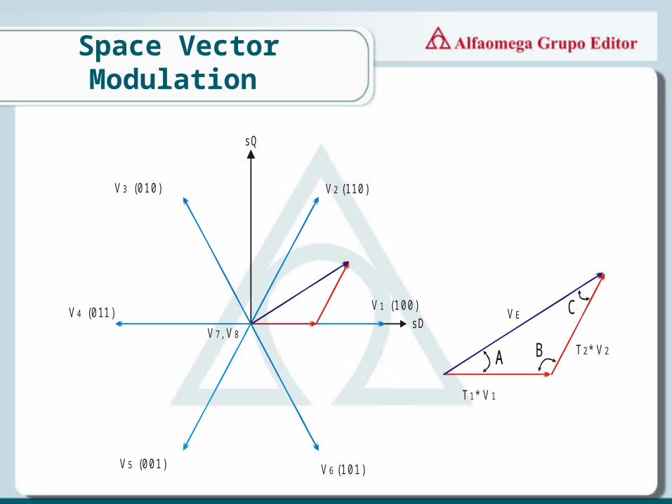
Space Vector Modulation
1sQ
1sDV1 (100)
V2 (110)V3 (010)
V4 (011)
V5 (001) V6 (101)
V7, V8
T * V 11
T * V22
VE
AA B
C
A
VT
C
VT
B
VEsin
*
sin
*
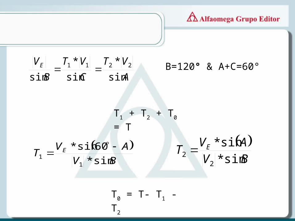
sin2211 B=120° & A+C=60°
T1 + T2 + T0 = T
BV
AVT E
sin*
60sin*
11
BVAV
T E
sin*sin*
22
T0 = T- T1 - T2
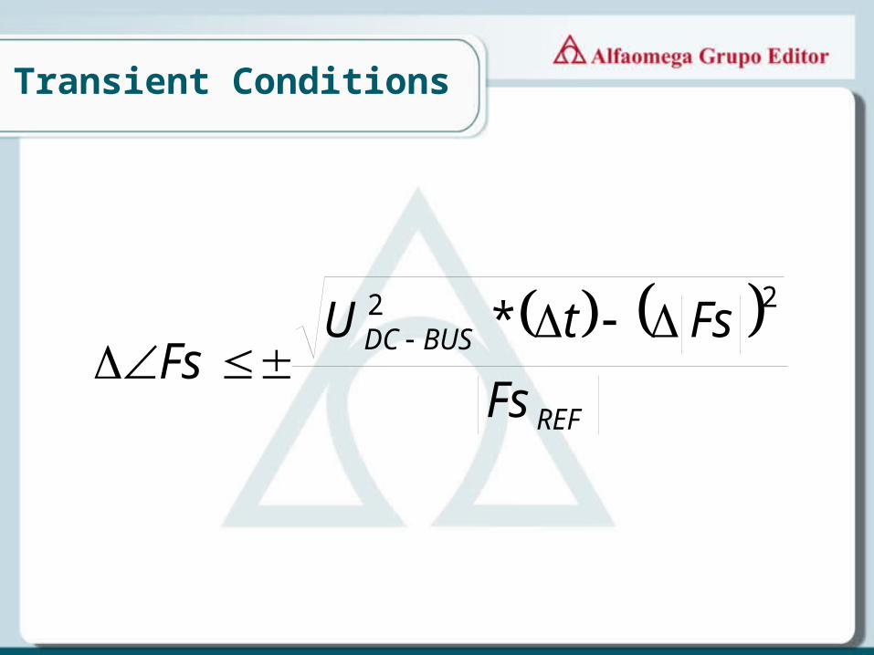
Transient Conditions
REF
BUSDC
Fs
FstUFs
22 *

Simulation Results
• A = 0; B= 300 , and C Reference
(A)
A = 0; B = 150; C = 250 and D = 300
(B)
Torque (A) and stator flux response (B).

Stator flux locus
Stator flux response in constant-torque and Field weakening regions for =300
and HB=0.002.
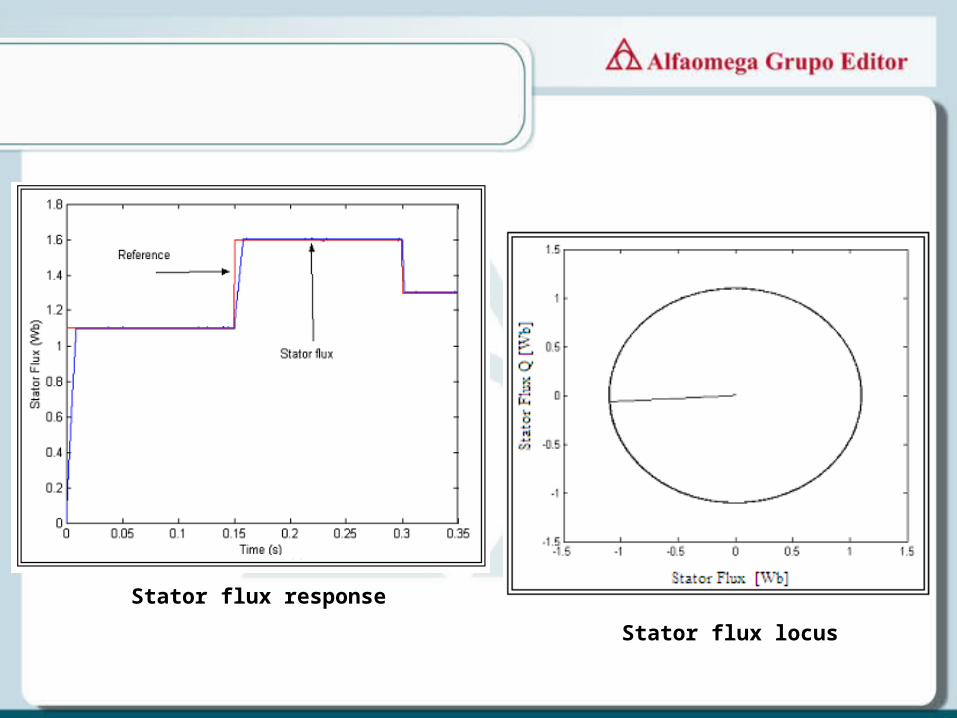
Stator flux response
Stator flux locus
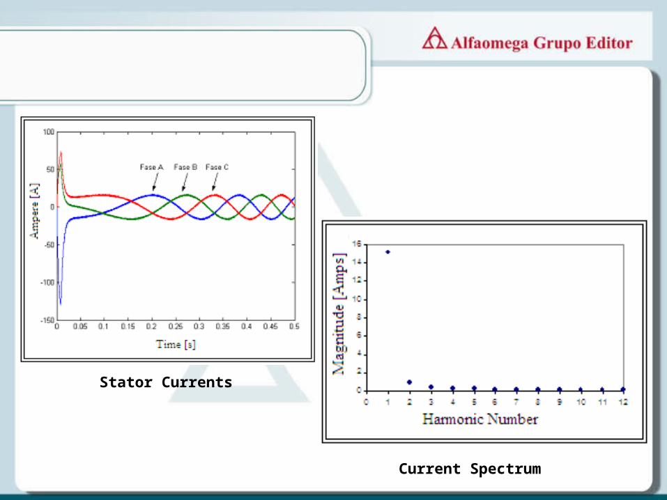
Stator Currents
Current Spectrum
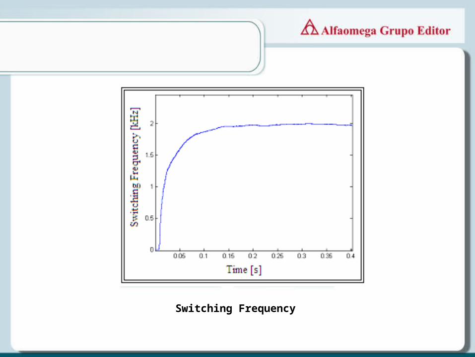
Switching Frequency
Top Related