


![Electrodynamic Dust Shield Demonstrator - Charles Stankie [20140002676]](https://static.fdocuments.in/doc/165x107/577cc7031a28aba7119fc364/electrodynamic-dust-shield-demonstrator-charles-stankie-20140002676.jpg)


Languages
Pages
Legal


Fundamentals ofElectrodynamic Vibration
Testing Handbook
g
Introduction................................2
A. Electrodynamic Shakers
Size & Force...........................3
Displacement, Velocity,
& Acceleration........................3
Frequency Range....................4
Armatures................................4
Centering & Support.............. 5
Head Expanders & Plates.......5
Fixturing..................................6
Sliptables.................................6
Cooling....................................7
Chamber Interface.................. 7
Vibration Isolation..................8
Noise Levels...........................8
B. Vibration Modes
Random...................................9
Real Data Acquisition
& Playback (RDAP)...............9
Sine with Resonant Search
& Dwell................................ 10
Classical Shock.....................10
Shock Response
Spectrum (SRS)....................11
Sine-on-Random...................11
Random-on-Random.............11
C. Amplifier Console.............. 12
Inverters................................12
Magnetic Field Power
Supply...................................12
Console Design.....................12
D. Vibration Controllers &
Instrumentation..................13
Software................................13
Dynamic Range.................... 14
Spectral Resolution...............14
Data Acquisition...................15
E. Accelerometers
Advantages & Size............... 16
Mounting..............................16
Types & Conditioning..........17
Sensitivity & Environments.18
F. Universal Vibration
Calculator........................... 19
G. References, Resources
& Websites.......................... 19
H. Move-in & Installation
Questions
& Considerations.............. 20
I. Handy Equations &
Engineering Reference.......23
J. Handy Conversion Factors
& Materials Properties......24
Written and published by
Thermotron Industries,
Holland, MI
Copyright 2006.
1gElectrodynamic Vibration Handbook
Table Of Contents
g
Vibration testing is performed for
a variety of reasons: to determine
if a product can withstand the rig-
ors of its intended use environ-
ment, to insure the final design
will not fall apart during shipping,
for Environmental Stress
Screening to weed out production
defects, or even as a form of
Accelerated Stress Testing.
Vibration tests are commonly used
to improve the reliability of mili-
tary hardware, avionics instrumen-
tation, consumer electronics, auto-
motive components, and telecom-
munications gear.
Electrodynamic vibration systems
are capable of performing many
different tests that specify sine,
random, shock, sine-on-random,
random-on-random and other com-
plex waveforms as well as repli-
cating data that is collected from
real world conditions.
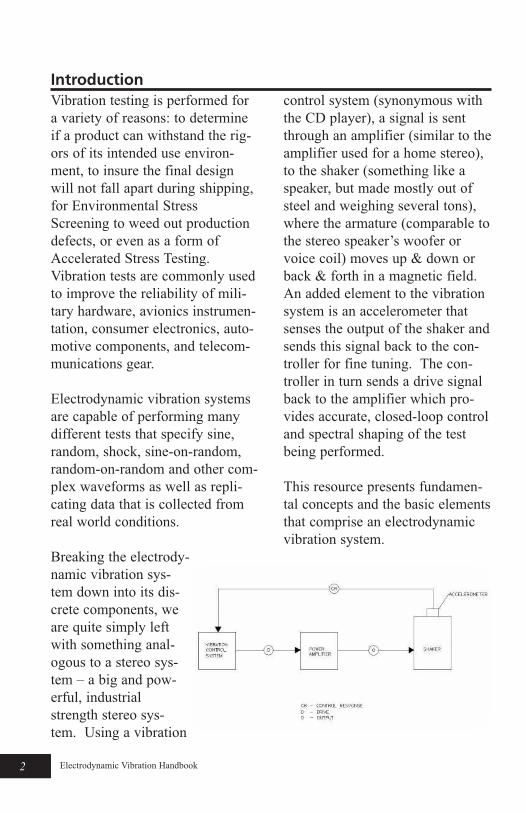
Breaking the electrody-
namic vibration sys-
tem down into its dis-
crete components, we
are quite simply left
with something anal-
ogous to a stereo sys-
tem – a big and pow-
erful, industrial
strength stereo sys-
tem. Using a vibration
control system (synonymous with
the CD player), a signal is sent
through an amplifier (similar to the
amplifier used for a home stereo),
to the shaker (something like a
speaker, but made mostly out of
steel and weighing several tons),
where the armature (comparable to
the stereo speaker’s woofer or
voice coil) moves up & down or
back & forth in a magnetic field.
An added element to the vibration
system is an accelerometer that
senses the output of the shaker and
sends this signal back to the con-
troller for fine tuning. The con-
troller in turn sends a drive signal
back to the amplifier which pro-
vides accurate, closed-loop control
and spectral shaping of the test
being performed.
This resource presents fundamen-
tal concepts and the basic elements
that comprise an electrodynamic
vibration system.
2g Electrodynamic Vibration Handbook
Introduction

g
Size & Force (F=ma)
When sizing an electrodynamic
shaker for a specific application
you need to first take into account
two essential factors. What is the
moving mass
(armature, fixture and product)
and what acceleration level needs
to be achieved? Multiplying these
two factors together provides the
force required to perform the test
function. In the event that the
shaker is attached to a sliptable,
the mass of the slip plate and driv-
er bar attachment must be
accounted for. When a shaker
interfaces with an environmental
test chamber, the mass of the ther-
mal barrier must be added to the
total moving mass. Don’t forget
to account for miscellaneous mass
that might
otherwise be
overlooked
such as: head
expanders or
plates, bolts &
nuts, cables,
etc. Force can
be expressed
in the English
units, lbf or
the metric
equivalent,
kN. It is not
uncommon
for the manufacturer of vibration
systems to derate actual shaker
force capabilities to 80% of their
true value as a measure of conser-
vative safety.
Displacement, Velocity &
Acceleration
The three functional limits to elec-
trodynamic shaker performance
are displacement, velocity and
acceleration. Displacement limits
shaker operation at the lowest fre-
quencies, and acceleration limits
the shaker performance at the
highest frequencies. Velocity lim-
its shaker performance in a band
between the other two limits. As
an example, Thermotron’s DS-
2250 vibration system has a dis-
placement limit of 2” peak-peak, a
velocity
limit of
100 inches
per second,
and an
accelera-
tion limit
of 100 g’s.
Each of
those limits
applies
over a dif-
ferent fre-
quency
range.
3gElectrodynamic Vibration Handbook
A. Electrodynamic Shakers
An example of a Force calculationF=ma
Vertical Horizontal
Product Mass 25 lb 25 lb
Fixture Mass 40 lb 40 lb
Cables Mass 2 lb 2 lb
Head ExpanderMass
60 lb NA
Slipplate Mass NA 65 lb
Armature Mass 23 lb 23 lb
Total Mass 150 lb 155 lb
Acceleration Level 10 g 10 g
Force Required 1500 lbf 1550 lbf
Displacement of an electrodynam-
ic shaker is a function of how far
up and down the armature is capa-
ble of traveling. Most shaker sys-
tems are limited to 2” (50 mm)
peak-to-peak travel. This means
that an armature can travel up one
inch (25 mm) and down one inch
(25 mm) from its center position.
It is standard practice to protect
the shaker from overtravel situa-
tions by utilizing sensors that shut
the system down before the
mechanical limits of the shaker are
exceeded.
Velocity is the speed at which the
armature can move. Velocity limits
for electrodynamic shakers can
reach 100 inches per second (2.5
m/sec). The higher the velocity
limit, the greater the shaker’s capa-
bility of attaining a wider range of
shock pulses.
Acceleration is expressed in terms
of gravitational units or g’s. A sin-
gle g is equal to the acceleration
due to gravity 32 ft/sec2 (9.8
m/sec2), 2 g’s is twice the acceler-
ation due to gravity and so on.
When the term grms is encoun-
tered, it is used to specify the rms
(root mean square) g level of a
random acceleration profile. Sine
and shock acceleration levels are
expressed in terms of g pk, where
pk stands for peak. The accelera-
tion component of a vibration test
is typically prescribed by the test
specification.
Frequency Range
Electrodynamic shakers operate
through a wide frequency range
that is typically from 5 Hz to 3,000
Hz. Most test specifications in the
automotive and transportation
industry emphasize low frequen-
cies (ie: below 1,000 Hz) while
military vibration specifications
normally call for testing out to
2,000Hz and electronics industry
specs can go as high as 3,000 Hz.
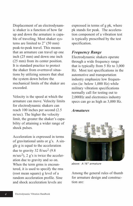
Armatures
Among the general rules of thumb
for armature design and construc-
tion are:
4g Electrodynamic Vibration Handbook
above: A 16” armature
• A lightweight armature is favor-
able and will permit testing at
higher g levels.
• The armature structure should
provide a significant amount of
stiffness.
• Material of construction is often
magnesium or aluminum.
• Magnesium has a very high
strength-to-weight ratio and
provides superior damping,
making it a favored material.
• Smaller lighter armatures may
be appropriate for testing small-
er products, while larger arma-
tures can eliminate the need to
use a head expander, reducing
system mass and improving
transmissibility.
Centering & Support
The armature needs to remain cen-
tered in its travel. Using an opti-
cal sensor to locate the armature
and an automated pneumatic fill &
drain system, the armature, bare
table or loaded, will stay true to its
course. Merely centering the
armature at the beginning of a test
is neither adequate nor safe.
Advanced systems possess the
ability to continuously center the
armature while a test is in
progress. Another feature of most
shakers is a centerpole and bearing
shaft that helps to keep the arma-
ture properly aligned during oper-
ation. It is good practice to load
fixture and product weight over
the center of the armature to avoid
overturning moments. In the
event the payload center of gravity
cannot be located over the center
of the armature, additional guid-
ance may need to be added to the
system to prevent shaker damage.
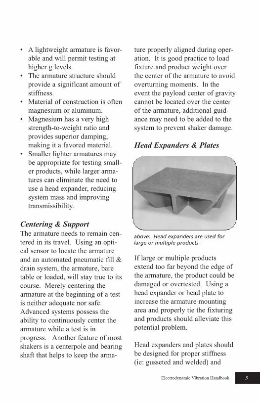
Head Expanders & Plates
If large or multiple products
extend too far beyond the edge of
the armature, the product could be
damaged or overtested. Using a
head expander or head plate to
increase the armature mounting
area and properly tie the fixturing
and products should alleviate this
potential problem.
Head expanders and plates should
be designed for proper stiffness
(ie: gusseted and welded) and
5gElectrodynamic Vibration Handbook
above: Head expanders are used forlarge or multiple products
should not be bolt-together struc-
tures since bolted joints reduce
energy transmission. Favored
materials of construction are mag-
nesium or aluminum.
Fixturing
In addition to acting as a mounting
interface between the shaker and
the product to be tested, a vibra-
tion fixture needs to be rigid and
lightweight. The vibration fixture
should also transmit a uniform dis-
tribution of energy from the arma-
ture to the test item. In many
cases, vibration is applied in three
orthogonal axes. Specialized
vibration fixture designs permit the
fixture to be rotated for testing in
the X, Y, and Z axis. It is common
to find the weight of a fixture to be
two to three times heavier than the
products to be tested. Fixtures
should mount easily to the arma-
ture and products should mount
easily to the fixture. Quick
changes from product to product
and axis to axis help to maximize
equipment utilization and improve
lab productivity.
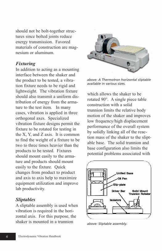
Sliptables
A sliptable assembly is used when
vibration is required in the hori-
zontal axis. For this purpose, the
shaker is mounted in a trunnion
which allows the shaker to be
rotated 90°. A single piece table
construction with a solid
trunnion limits the relative body
motion of the shaker and improves
low frequency/high displacement
performance of the overall system
by solidly linking all of the reac-
tion mass of the shaker to the slipt-
able base. The solid trunnion and
base configuration also limits the
potential problems associated with
6g Electrodynamic Vibration Handbook
above: Sliptable assembly.
above: A Thermotron horizontal sliptableavailable in various sizes.
misalignment which can plague a
two piece system. Beyond
the standard oil film systems, sev-
eral options such as guideline
tracking and hydrostatic bearings,
are available to further control true
and consistent horizontal vibration
performance.
Cooling
Shakers consume significant elec-
trical power which is converted to
heat. Cooling of field coils and
armature coils is mandatory in an
electrodynamic vibration system.
Shakers up to 15,000 lbf are typi-
cally air-cooled,
while high force
shakers (20,000 lbf
and above) are liq-
uid-cooled. Air-
cooled shakers can
be set up to exhaust
warm air outside
the facility during
warm months.
Provisions can be
made to damper the
warm air back into
the facility during
colder months.
The blower for an
air-cooled shaker
can be mounted
outdoors or it can be
placed in a sound deadening pack-
age and remain indoors.
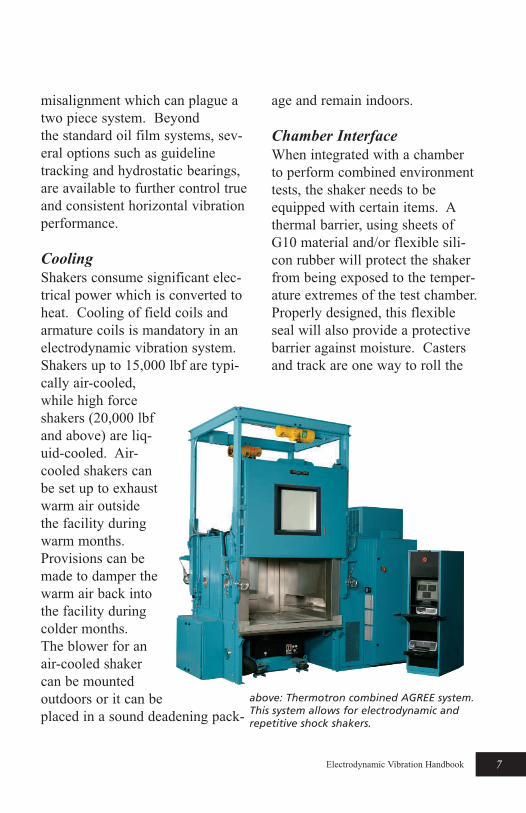
Chamber Interface
When integrated with a chamber
to perform combined environment
tests, the shaker needs to be
equipped with certain items. A
thermal barrier, using sheets of
G10 material and/or flexible sili-
con rubber will protect the shaker
from being exposed to the temper-
ature extremes of the test chamber.
Properly designed, this flexible
seal will also provide a protective
barrier against moisture. Casters
and track are one way to roll the
7gElectrodynamic Vibration Handbook
above: Thermotron combined AGREE system.This system allows for electrodynamic andrepetitive shock shakers.

shaker under a chamber. Another
option is to utilize an air-glide sys-
tem that floats the shaker on a
cushion of compressed air.
Applications where the shaker
remains fixed in its position and
the chamber rolls back and forth
present another viable option.
The ability to generate and run
sophisticated combined environ-
ment tests from a single user inter-
face can be a huge advantage.
This simplifies data entry and syn-
chronizes the individual pieces of
equipment so they work in concert
to carry out a fully integrated test.
Vibration Isolation
Electrodynamic shakers are capa-
ble of generating high forces over
a wide range of frequencies. To
limit the amount of unwanted
vibration energy from being trans-
mitted into the floor and through-
out the facility, pneumatic mounts
between the shaker and the floor
are filled with compressed air to
isolate the transmission of this
energy. Shakers are relatively
heavy pieces of equipment and, as
such, are typically mounted on the
ground floor of the facility.
Noise Levels
An electrodynamic shaker running
a full force random profile can be
as loud as a jet engine. While per-
forming a sine sweep to find a res-
onance point, the shaker can start
out as a low-pitched hum and rise
to an ear piercing scream. It is for
these reasons that a sound enclo-
sure should house the shaker sys-
tem. It is a wise idea to place the
control and amplifier console out-
side of the room for purposes of
safety and comfort. A multi-pane
window providing a view from the
control room into the shaker room
is advised for those situations
where visual access to the product
under test is critical.
8g Electrodynamic Vibration Handbook
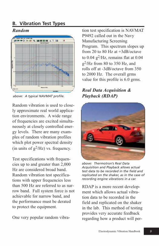
Random
Random vibration is used to close-
ly approximate real world applica-
tion environments. A wide range
of frequencies are excited simulta-
neously at closely controlled ener-
gy levels. There are many exam-
ples of random vibration profiles
which plot power spectral density
(in units of g2/Hz) vs. frequency.
Test specifications with frequen-
cies up to and greater than 2,000
Hz are considered broad band.
Random vibration test specifica-
tions with upper frequencies less
than 500 Hz are referred to as nar-
row band. Full system force is not
achievable for narrow band, and
the performance must be derated
to protect the equipment.
One very popular random vibra-
tion test specification is NAVMAT
P9492 called out in the Navy
Manufacturing Screening
Program. This spectrum slopes up
from 20 to 80 Hz at +3dB/octave
to 0.04 g2/Hz, remains flat at 0.04
g2/Hz from 80 to 350 Hz, and
rolls off at -3dB/octave from 350
to 2000 Hz. The overall grms
value for this profile is 6.0 grms.
Real Data Acquisition &
Playback (RDAP)
RDAP is a more recent develop-
ment which allows actual vibra-
tion data to be recorded in the
field and replicated on the shaker
in the lab. This method of testing
provides very accurate feedback
regarding how a product will per-
9gElectrodynamic Vibration Handbook
B. Vibration Test Types
above: A typical NAVMAT profile.
above: Thermotron’s Real DataAcquisition and Playback allows actualtest data to be recorded in the field andreplicated on the shaker, as in the case ofrecording engine vibrations in a car.
form under normal operating con-
ditions. Recorded vibration levels
can be stepped-up to higher levels
to accelerate the stress testing
process if so desired.
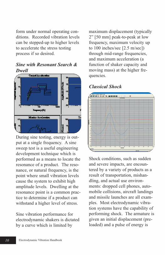
Sine with Resonant Search &
Dwell
During sine testing, energy is out-
put at a single frequency. A sine
sweep test is a useful engineering
development technique which is
performed as a means to locate the
resonance of a product. The reso-
nance, or natural frequency, is the
point where small vibration levels
cause the system to exhibit high
amplitude levels. Dwelling at the
resonance point is a common prac-
tice to determine if a product can
withstand a higher level of stress.
Sine vibration performance for
electrodynamic shakers is dictated
by a curve which is limited by
maximum displacement (typically
2” [50 mm] peak-to-peak at low
frequency, maximum velocity up
to 100 inches/sec [2.5 m/sec])
through mid-range frequencies,
and maximum acceleration (a
function of shaker capacity and
moving mass) at the higher fre-
quencies.
Classical Shock
Shock conditions, such as sudden
and severe impacts, are encoun-
tered by a variety of products as a
result of transportation, mishan-
dling, and actual use environ-
ments: dropped cell phones, auto-
mobile collisions, aircraft landings
and missile launches are all exam-
ples. Most electrodynamic vibra-
tion systems have the capability of
performing shock. The armature is
given an initial displacement (pre-
loaded) and a pulse of energy is
10g Electrodynamic Vibration Handbook
delivered by the amplifier which
translates into a particular wave-
form. Classical shock pulses are
determined by shape, amplitude
and duration. The most common
are half sine, sawtooth, triangular,
and trapezoidal.
Shock Response Spectrum
(SRS)
SRS Testing is a way to synthesize
a complex waveform that can be
used on an electrodynamic shaker
in a controlled manner with
repeatability. This avoids the
inconsistencies of shock test
machines that limit the shape of
the excitation pulse. SRS is a use-
ful tool for estimating the potential
damage of a shock pulse. SRS
tests are used to qualify equipment
installed in nuclear power plants
as well as to simulate seismic,
pyrotechnic, gun fire and aircraft
take-off and landing vibrations.
Sine-on-Random
Certain applications involving
rotating equipment in moving
vehicles require a vibration profile
that combines fixed or swept sine
and random vibration. Sine-on-
Random software simulates the
vibration environment experienced
by helicopters, automobiles, and
trains where the sine component
of a rotor or a reciprocating piston
engine is placed on top of a broad-
band random vibration profile
indicative of the moving vehicle.
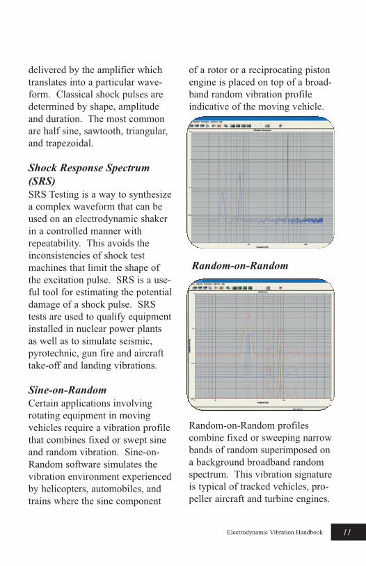
Random-on-Random
Random-on-Random profiles
combine fixed or sweeping narrow
bands of random superimposed on
a background broadband random
spectrum. This vibration signature
is typical of tracked vehicles, pro-
peller aircraft and turbine engines.
11gElectrodynamic Vibration Handbook
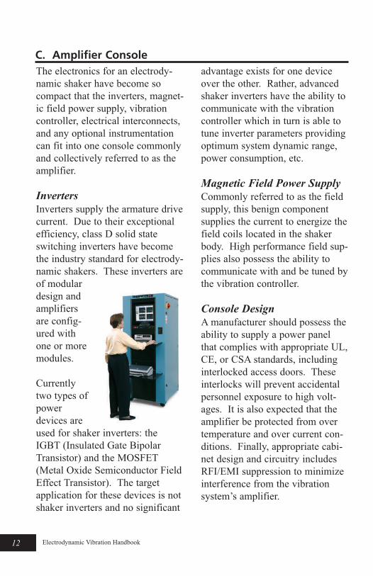
The electronics for an electrody-
namic shaker have become so
compact that the inverters, magnet-
ic field power supply, vibration
controller, electrical interconnects,
and any optional instrumentation
can fit into one console commonly
and collectively referred to as the
amplifier.
Inverters
Inverters supply the armature drive
current. Due to their exceptional
efficiency, class D solid state
switching inverters have become
the industry standard for electrody-
namic shakers. These inverters are
of modular
design and
amplifiers
are config-
ured with
one or more
modules.
Currently
two types of
power
devices are
used for shaker inverters: the
IGBT (Insulated Gate Bipolar
Transistor) and the MOSFET
(Metal Oxide Semiconductor Field
Effect Transistor). The target
application for these devices is not
shaker inverters and no significant
advantage exists for one device
over the other. Rather, advanced
shaker inverters have the ability to
communicate with the vibration
controller which in turn is able to
tune inverter parameters providing
optimum system dynamic range,
power consumption, etc.
Magnetic Field Power Supply
Commonly referred to as the field
supply, this benign component
supplies the current to energize the
field coils located in the shaker
body. High performance field sup-
plies also possess the ability to
communicate with and be tuned by
the vibration controller.
Console Design
A manufacturer should possess the
ability to supply a power panel
that complies with appropriate UL,
CE, or CSA standards, including
interlocked access doors. These
interlocks will prevent accidental
personnel exposure to high volt-
ages. It is also expected that the
amplifier be protected from over
temperature and over current con-
ditions. Finally, appropriate cabi-
net design and circuitry includes
RFI/EMI suppression to minimize
interference from the vibration
system’s amplifier.
12g Electrodynamic Vibration Handbook
C. Amplifier Console
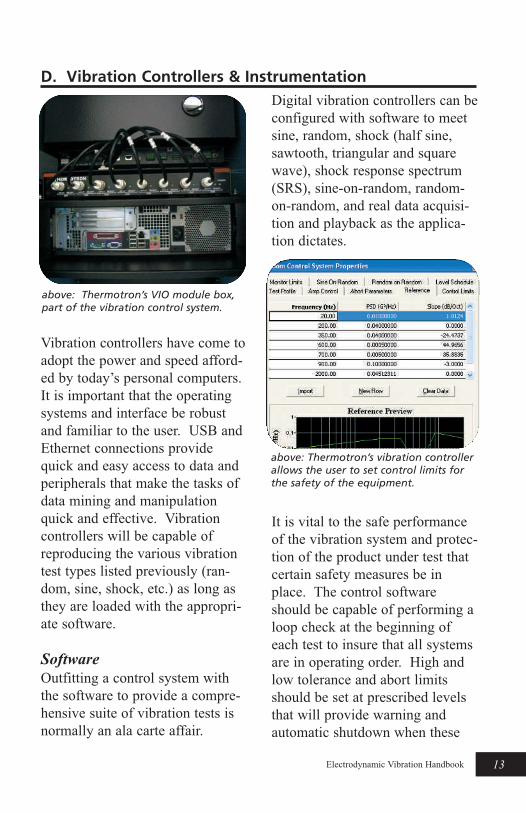
Vibration controllers have come to
adopt the power and speed afford-
ed by today’s personal computers.
It is important that the operating
systems and interface be robust
and familiar to the user. USB and
Ethernet connections provide
quick and easy access to data and
peripherals that make the tasks of
data mining and manipulation
quick and effective. Vibration
controllers will be capable of
reproducing the various vibration
test types listed previously (ran-
dom, sine, shock, etc.) as long as
they are loaded with the appropri-
ate software.
Software
Outfitting a control system with
the software to provide a compre-
hensive suite of vibration tests is
normally an ala carte affair.
Digital vibration controllers can be
configured with software to meet
sine, random, shock (half sine,
sawtooth, triangular and square
wave), shock response spectrum
(SRS), sine-on-random, random-
on-random, and real data acquisi-
tion and playback as the applica-
tion dictates.
It is vital to the safe performance
of the vibration system and protec-
tion of the product under test that
certain safety measures be in
place. The control software
should be capable of performing a
loop check at the beginning of
each test to insure that all systems
are in operating order. High and
low tolerance and abort limits
should be set at prescribed levels
that will provide warning and
automatic shutdown when these
13gElectrodynamic Vibration Handbook
D. Vibration Controllers & Instrumentation
above: Thermotron’s VIO module box,part of the vibration control system.
above: Thermotron’s vibration controllerallows the user to set control limits forthe safety of the equipment.
out-of-range limits are exceeded.
Dynamic Range
The dynamic range of a system is
the largest signal amplitude that
the entire system can process
divided by the inherent noise of
the system. It is also used to indi-
cate the number of bits (resolution)
of the data converters used in a
vibration controller. There are
roughly 6 decibels (dB) of dynam-
ic range per bit.
Inexpensive professional audio
grade 24 bit data converters are
making their way into vibration
controllers. The target market for
these converters are not vibration
controllers, and they do not pro-
vide the best solution for the appli-
cation. It is important to remem-
ber the vibration controller is part
of a control system consisting of
itself, an amplifier, and a shaker.
Therefore, the dynamic range of
the system is subject to the “chain
is only as strong as its weakest
link” principle - meaning the
dynamic range of the system can-
not be better than the dynamic
range of any single component of
the system.
Since state of the art inverters and
shakers are hard pressed to provide
60 dB of dynamic range, a vibra-
tion controller with 10 to 12 bit
data converters used in conjunc-
tion with a properly designed pro-
grammable input amplifier can
outperform a vibration controller
with 24 bit converters. The high
resolution data converters are
essentially using their “extra” bits
as a limited programmable input
amplifier when used in vibration
controller applications.
High performance vibration con-
trollers also possess the ability to
communicate with the amplifier’s
inverters and field supply to maxi-
mize system dynamic range.
Spectral Resolution
Spectral resolution, commonly
referred to as lines, or bins, is the
number of frequency segments that
a random vibration profile is divid-
ed into. The higher the spectral
resolution, the greater the number
of points used to calculate and
control the test frequency spec-
trum.
Current hardware and software
algorithms make it a simple matter
for a controller manufacturer to
add absurd amounts of lines. For
any random vibration profile, the
time it takes to acquire the data is
14g Electrodynamic Vibration Handbook
directly proportional to the num-
ber of lines. There is no known
way to sidestep this physical con-
straint. This added acquisition
time adversely effects the time it
takes the controller to correct any
errors in the random vibration pro-
file. Experts in the field rarely use
more than 800 lines. For example,
a controller will take 20 times
longer to correct a 16,000 line test
than it would for an 800 line test.
The number of lines are user
selectable. In the hands of a
novice user, this “feature” of many
lines could actually be detrimen-
tal.
Data Acquisition
Most controllers are capable of
accommodating multiple
accelerometer inputs. These
accelerometers can be used to
monitor or control the vibration
response characteristics at various
locations on the product under
test, the fixture, or the armature.
The results of data acquired during
vibration testing can be used to
prove the vibration test was com-
pleted successfully. Data acquired
in this manner can also be used to
determine how and why a product
may have failed.
In addition to monitoring, it is also
beneficial in certain circumstances
to control the vibration spectrum
based on more than one input
accelerometer signal. The vibra-
tion controller should have the
capability of supporting various
control strategies such as multi-
point averaging, maximum or
minimum, etc.
15gElectrodynamic Vibration Handbook
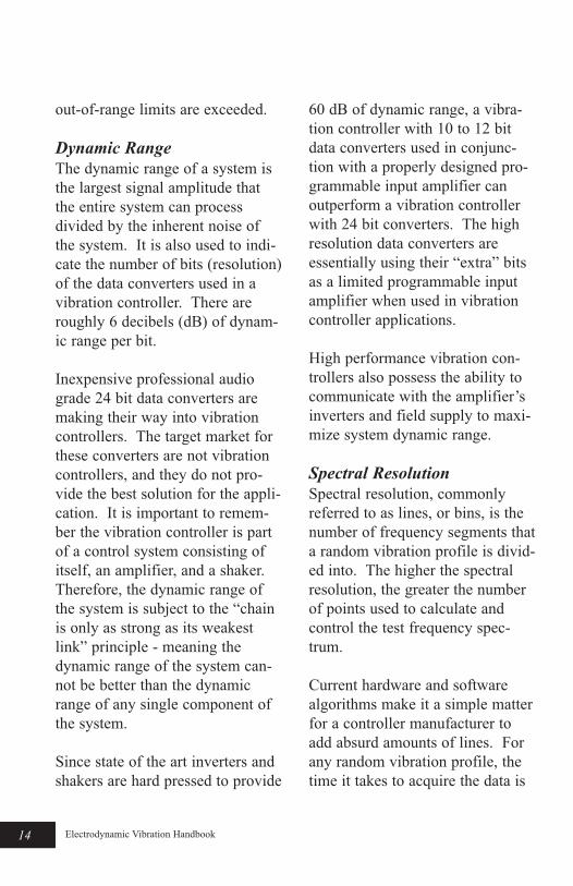
above: Thermotron’s vibration controlsoftware allows up to eight channels ofinput.
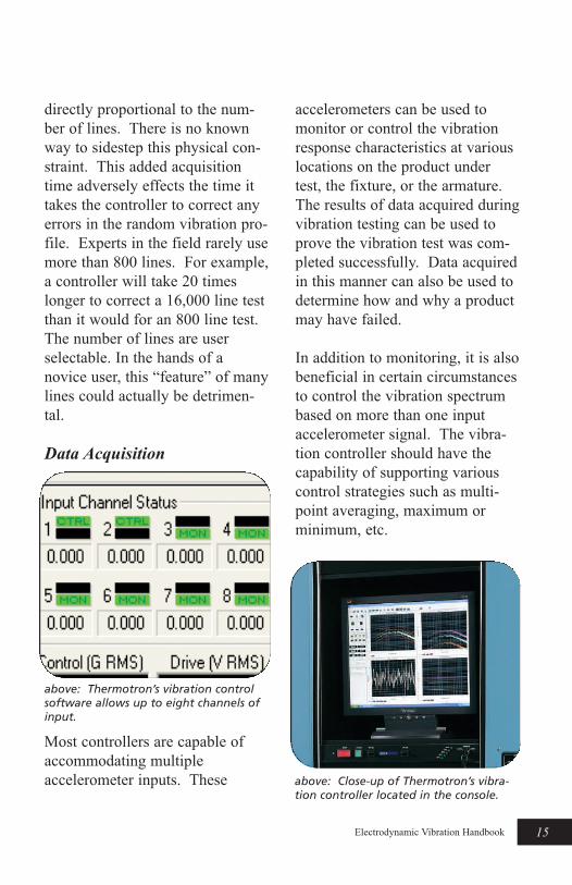
above: Close-up of Thermotron’s vibra-tion controller located in the console.

Advantages & Size
An accelerometer is a device that
senses the motion of the surface to
which it is attached, providing an
electrical output signal.
Piezoelectric materials are used in
accelerometers that produce a
“charge” proportional to the
motion. Years ago larger velocity
type pickups were used to measure
vibration. These were bulky and
had a limited frequency range.
Accelerometers are now made
mechanically smaller and have a
wide frequency range (2-10,000
Hz). Typical weights of
accelerometers used on shakers
range from a few grams (miniature
accelerometers) to 10 or 20 grams
(general purpose accelerometers).
Mounting
For accurate measurements, it is
important that accelerometers be
mounted correctly on shaker sys-
tems. The mounting surfaces
between the accelerometer and
surface should be smooth and
clean. The two most common
methods of mounting accelerome-
ters are threaded stud mounting
and adhesive mounting.
Sometimes a non-conductive spac-
er is required to prevent unwanted
ground-loop interference.
Stud mounting is the preferred
method because the accelerometer
is tightly coupled to the surface
being measured, assuring excellent
transmissibility, especially at high
frequencies. A torque wrench set
to the manufacturer’s specification
is used to ensure repeatability and
prevent thread damage. A thin
layer of grease can be used to fill
any voids resulting in a joint with
16g Electrodynamic Vibration Handbook
above: Accelerometer mounted to a fix-ture on a shaker.
E. Accelerometers
above: Typical accelerometers in varioussizes.
improved stiffness. This type of
mounting is typically used on con-
trol accelerometers mounted on
fixtures.
Adhesive mounting is used when
it is impractical or impossible to
use the stud mounting method.
This technique is frequently used
when measuring the vibration
response from a product under
test. For this type of measurement
miniature accelerometers with
smooth, flat surfaces are well suit-
ed. A common and reliable adhe-
sive used is cyanoacrylate also
known as “Crazy Glue” or
“Instant Bond.” Removing the
adhesive mounted accelerometer
requires great care. Solvents
should be used to soften the bond,
supplemented by a light shearing
torque.
Types & Conditioning
Throughout the years two
accelerometer types have been
used:
1) Charge Mode
2) Voltage Mode
Charge mode accelerometers pro-
duce a high impedance charge
from internal crystals. Each
accelerometer has its own sensitiv-
ity in pC/g (pico coulomb per g).
This charge must be converted to
a voltage for vibration measure-
ment readout and analysis. Special
low noise cables are used for
charge mode accelerometers to
eliminate the adverse effects of
electrical noise and cable move-
ment. Devices called charge
amplifiers are connected to these
accelerometers to convert the
charge signal to a low impedance
voltage signal. Charge amplifiers
can be simple in-line devices or
complex instruments with sensi-
tivity dials and various outputs for
monitoring and analysis.
The most popular accelerometers
used today are the voltage mode
accelerometers. Voltage mode
accelerometers have an internal
amplifier that converts the high
impedance charge signal to a low
impedance output voltage signal.
A voltage mode accelerometer has
its sensitivity expressed in mV/g
(millivolts per g). The charge
amplifier is replaced by a current
source, typically 4 mA, that pow-
ers the internal amplifier. The
internal amplifier allows the
accelerometer to be conveniently
coupled to read-out instruments
(scopes, analyzers, meters, etc).
The low output impedance elimi-
nates the need for expensive low
noise cable.
17gElectrodynamic Vibration Handbook
Sensitivity & Environments
As mentioned earlier, each
accelerometer has its own output
sensitivity, either in pC/g or mV/g.
The sensitivity depends on the
piezo-electric properties of the
crystal used. Typically smaller
accelerometers have low sensitivi-
ties (0.5 pC/g, 1 mV/g, etc.) and a
wider frequency response. Larger
accelerometers have higher sensi-
tivities (10 pC/g, 100 mV/g, etc.)
but a lower frequency range.
Sensitivity and frequency response
are two important properties to
consider when selecting
accelerometers.
Another factor that should be con-
sidered is the environment in
which the accelerometer will be
operated. Humidity and extreme
temperatures can affect sensitivity.
Rapid change in temperatures can
cause thermal transients. For this
reason care should be taken when
selecting accelerometers to be used
under extreme environmental con-
ditions. Typical temperature limits
are -55°C to + 121°C for voltage
mode devices. Since charge mode
accelerometers do not have inter-
nal electronics, they can be
designed for operation at substan-
tially higher temperatures. Typical
temperature ranges for charge
mode accelerometers are from
-55°C to + 250°C.
18g Electrodynamic Vibration Handbook
A version of the calculator can be
downloaded from the Thermotron
website at:
http://www.thermotron.com/
resources/univconv.html
This tool will allow you to quickly
and conveniently calculate impor-
tant vibration parameters and
make common unit conversions.
G. References, Resources& WebsitesVibration Test Specifications
by Industry
Aerospace
RTCA
http://www.rtca.org
Automotive
SAE
http://www.sae.org
Electronics
IPC / JEDEC
http://www.ipc.org
Defense
MIL-STD
http://www.dscc.dca.mil
Telecommunications
Telcordia
http://telecom-info.telcordia.com
General Test Specifications
JIS
http://www.jsa.or.jp
IEC
http://www.iec.ch
IHS
http://www.ihs.com
Trade Publications
Evaluation Engineering
http://www.nelsonpub.com
IEST Journal
http://www.iest.org
Sound & Vibration
http://www.SandV.com
Test & Measurement World
http://www.tmworld.com
TEST Engineering & Management
http://www.mattingley-publ.com
19gElectrodynamic Vibration Handbook
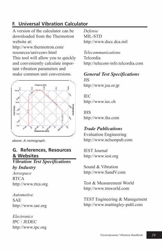
F. Universal Vibration Calculator
above: A nomograph.
Testing Technology International
http://www.ukintpress.com/test-
ing2.html
Technical Organizations
American National Standards
Institute (ANSI)
http://www.ansi.org
American Society for Quality
(ASQ)
http://www.asq.org
American Society for Testing and
Materials (ASTM)
http://www.astm.org
Institute of Environmental
Sciences and Technology (IEST)
http://www.iest.org
International Standards
Organization (ISO)
http://www.iso.ch
Shock and Vibration Information
Analysis Center (SAVIAC)
http://saviac.bah.com
MIL-STD Search
http://astimage.daps.dla.mil/quick-
search
Education and Training
Equipment Reliability Institute
www.equipment-reliability.com
Q1. What provisions are included
for lifting the shaker?
A1. Heavy duty eye bolts or lift-
ing ears are attached to the shaker
body. Straps or chains capable of
supporting the weight of the shak-
er are attached to the eye bolts or
lifting ears. A forklift hoists the
shaker up by the straps or chains
and gently moves and lowers the
shaker into place.
Q2. How do we deal with the
noise issue?
A2. Electrodynamic shakers are
extremely loud. Under the right
conditions, the vibration system
can sound like a jet engine ready
for take off. They should be
housed in an enclosure that has
very good absorbing qualities. If
the shaker is combined with a
chamber, the space below the
chamber can be enclosed with
sound absorbing panels. Baffled
air inlet ducts must be incorporat-
ed to supply the required flow of
cooling air.
Q3. Where should the control
console and amplifier be located?
A3. The control and amplifier
should be located in a quiet area.
Some installations have separate,
dedicated control rooms for this
equipment, while others simply
locate the controls outside the
20g Electrodynamic Vibration Handbook
H. Move-in & Installation Questions & Considerations
deadened booth. In the case of a
combined environment facility, the
amplifier and control instrumenta-
tion can be located next to the
chamber if the area is large
enough.
Q4. What networking connec-
tions need to be made?
A4. Shaker controls have become
quite sophisticated. They can be
run as stand-alone devices or be
connected to a local area network
via Ethernet. They can also be
remotely accessed via the internet
if so desired. PCs used to drive
the control algorithms are avail-
able with multiple USB connec-
tions that will support peripheral
appliances that will enhance data
transfer and storage as well as
other test and measurement instru-
ments.
Q5. Where should the cooling
blower be located?
A5. In a normal installation, the
blower is mounted in a remote
outdoor location, say on the roof
of the building. The cooling air is
drawn through the shaker body
and ducted out of the building.
The warm air can be diverted back
into the building during cold
months and used as a heat source.
Some blowers are mounted inside
the building. In this case, a quiet
package or sound deadening
enclosure built around the enclo-
sure should be considered.
Q6. Do we need a special floor
that will support the weight of the
shaker and eliminate vibration
transmission?
A6. Many low and medium force
shakers feature vibration isolation
systems that prevent energy from
being transmitted directly into the
facility floor. It is not uncommon
for a shaker’s mass to exceed
6,000 lbm (2,700 kg). A mass of
10,000 lbm (4,500 kg) or more
can be expected if a concrete filled
granite topped sliptable is includ-
ed.
Q7. Should the shaker roll or be
stationary?
A7. If the shaker is used strictly
for vibration testing at ambient
conditions, it should be left in a
stationary configuration. When
combined with a chamber, consid-
eration has to be given to whether
to move the shaker or the chamber
for product loading. The installa-
tion can be configured either way,
but it is more common to move
the shaker. If the chamber is
moved, provisions may need to be
made for flexible refrigeration
lines, and in extreme cases, raising
and lowering the chamber.
21gElectrodynamic Vibration Handbook
Chambers can also be designed with
several different door configurations.
When equipped with vertical lift doors
or horizontal sliding doors, moving the
chamber becomes much more chal-
lenging.
Q8. What is the best way to move a
shaker around?
A8. Some shakers have v-groove cast-
ers and mating sections of reinforced
steel track that allow them to be
moved back and forth (usually into
and out from under a test chamber).
An automated power tow can greatly
ease the rolling around of shakers.
Shakers are also available with an air-
glide transport system that permits the
equipment to be easily maneuvered on
a cushion of compressed air.
22g Electrodynamic Vibration Handbook

Shaker Force
The shaker force required is inde-
pendent of frequency and is calcu-
lated by the following force equa-
tion using weight in place of mass
and acceleration in normalized
units of standard g’s.
Shaker Force = (Payload mass +
Fixture mass + shaker Armature
mass) X Acceleration (g’s)
Units:
Sine: pounds force peak = (pounds
+ pounds + pounds) X g’s peak
Random: pounds force rms =
(pounds + pounds + pounds) X g’s
rms
Shaker Displacement &
Velocity
The required shaker displacement
is a strong function of low fre-
quencies. The table below of
sinusoidal motion equations can
be used to calculate the required
displacements and velocities for
sinusoidal vibration. Random dis-
placements and velocities must be
calculated from acceleration spec-
tral density information.
The universal vibration calculator
should be used to calculate dis-
placements and velocities require-
ments for random vibration test-
ing.
23gElectrodynamic Vibration Handbook
I. Handy Equations & Engineering Reference
Sinusoidal Equations of MotionAcceleration, velocity, displacement and frequency are related by two
independent equations, therefore specifying any two fully defines the
motion.
Known Values
g & f v & f D & f D & g v & g D & v
g (g’s)peak acceleration
f v/61.45 f2D/19.56 v2/193.0D
v (inch/sec.)peak velocity
61.45 g/f πfD 13.89 (gD)1/2
D (inch)pk-pk displacement
19.56 g/f2 v/πf v2/193.0 g
f (Hz)frequency 4.423 (g/D)1/2 61.45 g/v v/ πD
24g Electrodynamic Vibration Handbook
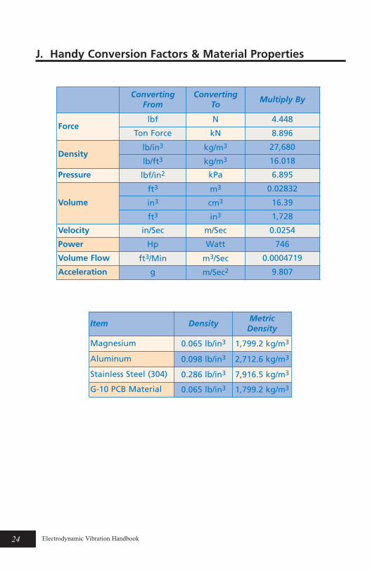
J. Handy Conversion Factors & Material Properties
ConvertingFrom
ConvertingTo
Multiply By
Forcelbf N 4.448
Ton Force kN 8.896
Densitylb/in3 kg/m3 27,680
lb/ft3 kg/m3 16.018
Pressure lbf/in2 kPa 6.895
Volume
ft3 m3 0.02832
in3 cm3 16.39
ft3 in3 1,728
Velocity in/Sec m/Sec 0.0254
Power Hp Watt 746
Volume Flow ft3/Min m3/Sec 0.0004719
Acceleration g m/Sec2 9.807
Item DensityMetric
Density
Magnesium 0.065 lb/in3 1,799.2 kg/m3
Aluminum 0.098 lb/in3 2,712.6 kg/m3
Stainless Steel (304) 0.286 lb/in3 7,916.5 kg/m3
G-10 PCB Material 0.065 lb/in3 1,799.2 kg/m3

Top Related