


Languages
Pages
Legal


MO
FLAME
ODELS: FW(Av
FLAME DETECTO
USE
FW2-IRW2-IR3S-A/ARvailable in Alu
EWATCOR with VIER MANUAL
R3S-A/AR shoR, FW2-UV/IRSuminum & Sta
Pa
CH II IDEO CAM
own S-A/AR & FW2
ainless Steel)
art Number: MAN Marc
MERA
2-UVS-A/AR
N-0120 Rev 0 Flach 30, 2010
ameWatch II

MAN-0120 Rev 0 FlameWatch II March 30, 2010 1
IMPORTANT INFORMATION This manual is for informational purposes only. Although every effort has been made to ensure the correctness of the information, technical inaccuracies may occur and periodic changes may be made without notice. Net Safety Monitoring Inc., assumes no responsibility for any error contained within this manual. This manual is a guide for using the FlameWatch II (IR3S, UV/IRS & UVS model Flame Detectors with the Surveillance Video Camera) product and the data and procedures contained within this document have been verified and are believed to be adequate for the intended use of the device. If the device or procedures are used for purposes other than as described in the manual without receiving prior confirmation of validity or suitability, Net Safety Monitoring Inc. does not guarantee the results and assumes no obligation or liability. No part of this manual may be copied, disseminated or distributed without the express consent of Net Safety Monitoring Inc. Net Safety Monitoring Inc. products are carefully designed and manufactured from high quality components and can be expected to provide many years of trouble free service. Each product is thoroughly tested, inspected and calibrated prior to shipment. Failures can occur which are beyond the control of the manufacturer. Failures can be minimized by adhering to the operating and maintenance instructions herein. Where the absolute greatest of reliability is required, redundancy should be designed into the system. WARRANTY Net Safety Monitoring Inc warrants this device against defective parts and workmanship for a period of for 36 months from date of purchase. No other warranties or liability, expressed or implied, will be honoured by Net Safety Monitoring Inc. Contact Net Safety Monitoring Inc. or an authorized representative for details. We welcome your input at Net Safety Monitoring Inc. If you have any comments please contact us at the telephone number or address below or visit our web-site, www.net-safety.com, and complete our on-line customer survey. CONTACT INFORMATION Net Safety Monitoring Inc Direct: (403) 219-0688 Corporate Headquarters Facsimile: (403) 219-0694 2721 Hopewell Place NE E-mail: [email protected] Calgary, AB. Canada T1Y 7J7

MAN-0120 Rev 0 FlameWatch II March 30, 2010 2
Table of Contents SECTION 1: INTRODUCTION ................................................................................................................................................................................... 4
1.1 Description ........................................................................................................................................................................................................... 4
1.1.1 Product Components: .................................................................................................................................................................................... 4
1.1.2 Available models .......................................................................................................................................................................................... 5
1.2 Unpack ................................................................................................................................................................................................................. 5
1.3 Mounting .............................................................................................................................................................................................................. 6
1.4 Field Installation .................................................................................................................................................................................................. 6
1.4.1 Installation Considerations ............................................................................................................................................................................ 6
1.5 Wiring .................................................................................................................................................................................................................. 6
1.6 Seal ....................................................................................................................................................................................................................... 7
1.7 FlameWatch II General Application .................................................................................................................................................................... 7
1.8 FlameWatch II Dimensional Drawing ................................................................................................................................................................. 7
Figure 1: Dimensional Drawing (Measurements are in Millimeters and Inches) ................................................................................................. 7
1.9 Mounting and Positioning FlameWatch II ........................................................................................................................................................... 8
Figure 2: Mounting and Installation. ..................................................................................................................................................................... 8
SECTION 2: Operation .................................................................................................................................................................................................. 9
2.1 FlameWatch II Junction Box Terminal Board ..................................................................................................................................................... 9
Figure 3: FlameWatch II Analog- Relay Terminal Board ..................................................................................................................................... 9
2.2 Relay configurations .......................................................................................................................................................................................... 10
2.3 Current Loop power configurations ................................................................................................................................................................... 11
SECTION 3: Wiring diagrams ..................................................................................................................................................................................... 12
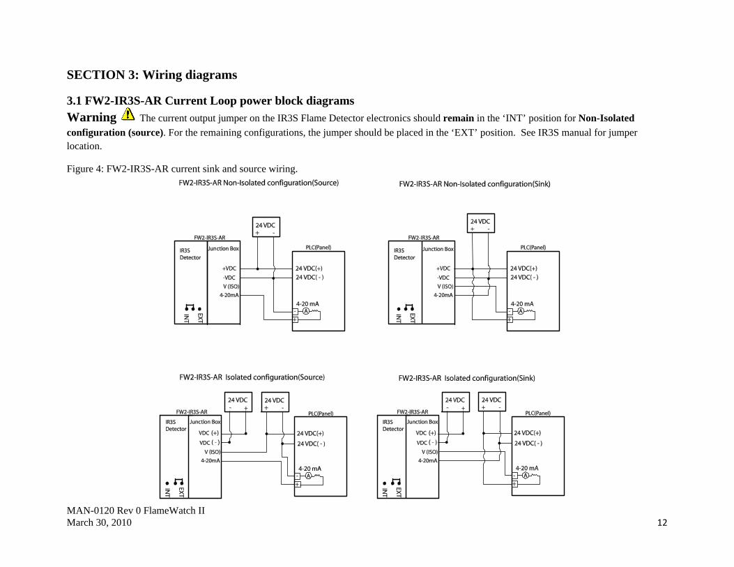
3.1 FW2-IR3S-AR Current Loop power block diagrams ........................................................................................................................................ 12

MAN-0120 Rev 0 FlameWatch II March 30, 2010 3
Figure 4: FW2-IR3S-AR current sink and source wiring. ................................................................................................................................... 12
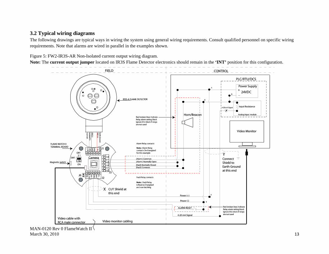
3.2 Typical wiring diagrams .................................................................................................................................................................................... 13
Figure 5: FW2-IR3S-AR Non-Isolated current output wiring diagram. .............................................................................................................. 13
Figure 6: FW2-IR3S-AR Isolated current output wiring diagram. ...................................................................................................................... 14
Figure 7: FW2-UV/IRS-AR & FW2-UVS-AR Non- Isolated current output wiring diagram. ........................................................................... 15
SECTION 4: Maintenance .......................................................................................................................................................................................... 16
4.1 Troubleshoot .......................................................................................................................................................................................................... 16
4.1.1 Spare Parts / Accessories ................................................................................................................................................................................ 16
HOW TO RETURN EQUIPMENT ............................................................................................................................................................................. 17
Appendix A: ELECTROSTATIC SENSITIVE DEVICE (ESD) ................................................................................................................................ 18
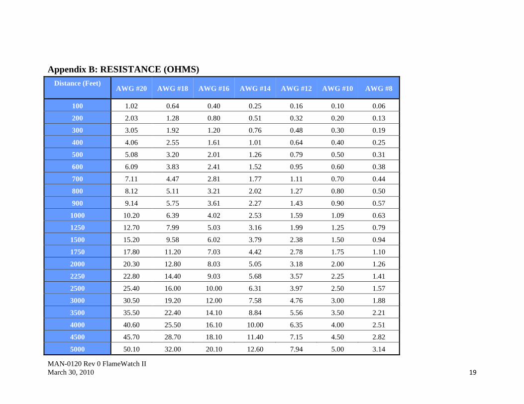
Appendix B: RESISTANCE (OHMS) ......................................................................................................................................................................... 19
Appendix B: Resistance Table (cont’d) ....................................................................................................................................................................... 20
Appendix C: Technical Specifications of Video Camera ............................................................................................................................................ 21
Appendix D: IR3S Flame Detector Technical Specifications ...................................................................................................................................... 22
Appendix E: UV/IRS Flame Detector Technical Specifications ................................................................................................................................. 23
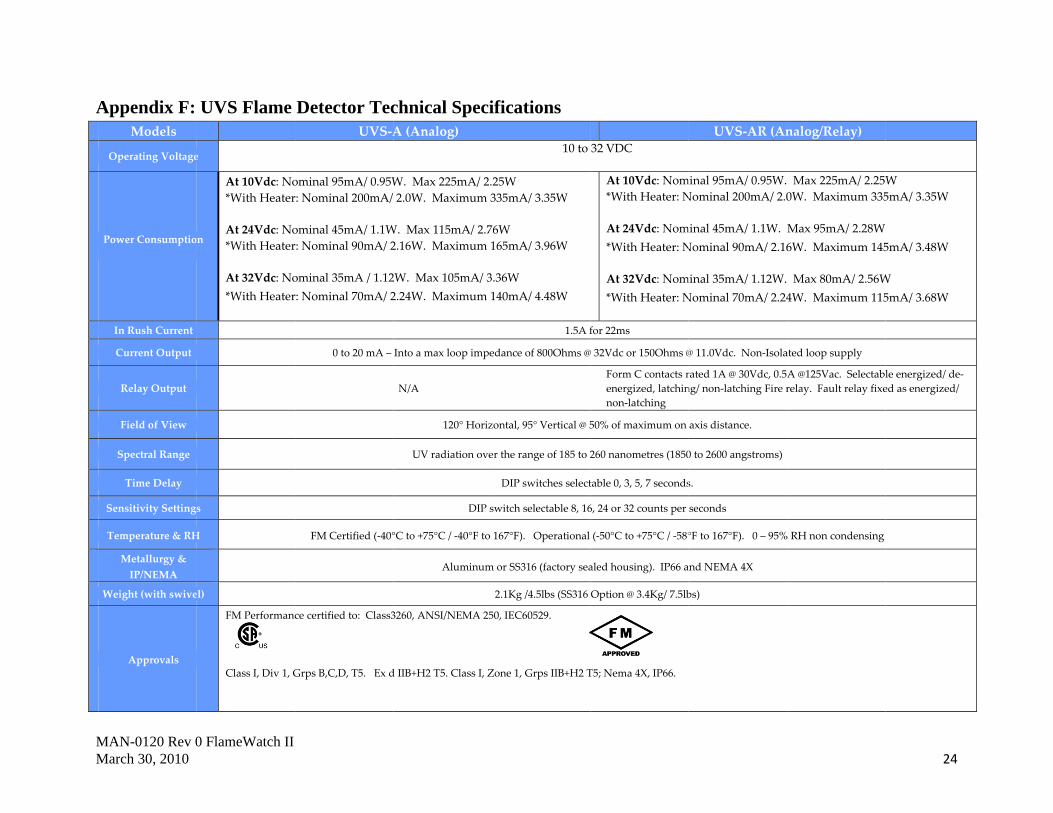
Appendix F: UVS Flame Detector Technical Specifications ...................................................................................................................................... 24

MAN-0120 Rev 0 FlameWatch II March 30, 2010 4
SECTION 1: INTRODUCTION
1.1 Description Net Safety’s latest upgrade in Flame detection with surveillance monitoring is the FlameWatch II product. It is light in weight, easy to install and allows flame detection coverage and intrusion monitoring over a wide area. The outputs available are analog (4-20 mA) signal and relay, along with video signal transmission via a shielded twisted pair cable. The unit will respond with the appropriate output signal whenever a fire is present, at the same time allow users real time viewing of the coverage area. With real time viewing, users can make on the spot critical decisions based on flame source, size and location. In addition to monitoring and viewing of fires, unauthorized entry into restricted areas may also be properly tracked. Users are provided the option of selecting the model Net Safety Flame Detector supplied with the Video Camera, which determines the model FlameWatch II. The choice in FlameWatch II is dependent on users’ preference, environment and application.
1.1.1 Product Components: FlameWatch II has two component products: A surveillance colour video camera and a Net Safety Flame Detector. The camera is fitted inside an explosion proof enclosure (junction box) and a flame detector is mounted on top of the enclosure by way of a sealed conduit. With this latest design, the video camera is allowed a wide field of view comparable to that of flame detectors. The types of flame detector available are: the Phoenix Triple IR (IR3S), the UV/IRS and the UVS. FlameWatch II is available in Aluminum (AL) and Stainless Steel (SS). Surveillance Video Camera: The field of view of the video camera is 100 degrees. This angle is wide enough to account for parallax errors between the flame detector and video camera. The camera employs digital signal processor (DSP) technology and delivers a composite video output for use with most monitoring systems/video monitors. The video formats available are the NTSC (National Television Systems Committee) and PAL (Phase Alternating Line) systems; users are able to choose between the NTSC formatted FlameWatch II product and the PAL formatted FlameWatch II product. Video output signal is delivered by a shielded twisted pair cable which has a male RCA connector attached. See Appendix C for video camera specifications. Triple IR FlameWatch II (FW2-IR3S-AR): The FW2-IR3S-AR is the incorporation of the surveillance video camera and the Phoenix Triple IR Flame Detector (IR3S). The IR3S Flame Detector is a triple spectrum IR detector designed to respond to infrared radiation emitted by a wide range of hydrocarbon based fires. Its state of the art design allows it to respond to specific IR frequencies generated by a flame source, while virtually eliminating response to sources of false alarms. The detector has a proven track record when compared to other IR flame detectors. It is not affected by rain in its line of sight or on its lens surface and shows immunity to arc welding, lightning and sparks. Because of these advantages, along with the wide field of view and high resolution of the video camera, the FW2-IR3S-AR can be used in both indoor and outdoor applications.
MAN-0120 Rev 0 FlameWatch II March 30, 2010 5
UV/IRS and UVS FlameWatch II (FW2-UV/IRS-AR and FW2-UVS-AR): The FW2-UV/IRS-AR is a combination of the surveillance video camera and the UV/IRS Flame Detector. The UV/IRS Flame Detector incorporates UV and IR detection circuitry to detect specific wavelengths in the UV and IR spectrums whenever a fire is present. This flame detector is designed to detect a wide range of hydrocarbon based fires and shows exceptional immunity against arc welding, hot body radiation, lightning and sunlight. With these attributes, along with the wide field of view and high resolution of the video camera, the FW2-UV/IRS-AR is suitable for indoor and outdoor applications. The FW2-UVS-AR is a combination of the surveillance video camera and the UVS Flame Detector. The UVS Flame Detector is designed to detect a wide range of hydrocarbon, hydrogen and metal based fires. This flame detector continually monitors coverage area for the presence of UV radiation specifically generated by a fire source. It shows great immunity to false alarm sources such as: incandescent or fluorescent sources, lightning, heaters and sunlight. With its immunity to false alarm sources and the attributes of the camera in mind, the FW2-UVS-AR is also well suited for indoor and outdoor applications.
1.1.2 Available models Aluminum (AL) models: FW2-UVS-A (FlameWatch II, UV, Analog, NTSC) / FW2-UVS-A-P (FlameWatch II, UV, Analog, PAL) FW2-UVS-AR (FlameWatch II, UV, Analog/Relay, NTSC) / FW2-UVS-AR- P (FlameWatch II, UV, Analog / Relay, PAL) FW2-UV/IRS-A (FlameWatch II, UV/IRS, Analog, NTSC) / FW2-UV/IRS-A-P (FlameWatch II, UV/IR, Analog, PAL) FW2-UV/IRS-AR (FlameWatch II, UV/IRS, Analog/Relay, NTSC) / FW2-UV/IRS-AR-P (FlameWatch II, UV/IR, Analog/Relay, PAL) FW2-IR3S-A (FlameWatch II, IR3S, Analog, NTSC) / FW2-IR3S-A-P (FlameWatch II, IR3S, Analog, PAL) FW2-IR3S-AR (FlameWatch II, IR3S, Analog/Relay, NTSC) / FW2-IR3S-AR-P (FlameWatch II, IR3S, Analog/Relay, PAL) Stainless Steel (SS) models: FW2-UVS-A-SS (FlameWatch II, UV, Analog, NTSC) / FW2-UVS-A-P-SS (FlameWatch II, UV, Analog, PAL) FW2-UVS-AR-SS (FlameWatch II, UV, Analog/Relay, NTSC) / FW2-UVS-AR-P-SS (FlameWatch II, UV, Analog / Relay, PAL) FW2-UV/IRS-A-SS (FlameWatch II, UV/IRS, Analog, NTSC) / FW2-UV/IRS-A-P-SS (FlameWatch II, UV/IR, Analog, PAL) FW2-UV/IRS-AR-SS (FlameWatch II, UV/IRS, Analog/Relay, NTSC) / FW2-UV/IRS-AR-P-SS (FlameWatch II, UV/IR, Analog/Relay, PAL) FW2-IR3S-A-SS (FlameWatch II, IR3S, Analog, NTSC) / FW2-IR3S-A-P-SS (FlameWatch II, IR3S, Analog, PAL) FW2-IR3S-AR-SS (FlameWatch II, IR3S, Analog/Relay, NTSC) / FW2-IR3S-AR-P-SS (FlameWatch II, IR3S, Analog/Relay, PAL)
1.2 Unpack Remove all packaging components from the box. Carefully remove the FlameWatch II unit by holding the junction box. Check components against the enclosed packing list and inspect all components for obvious damage such as broken or loose parts. Use the Net Safety lens cleaner to clean the flame detector’s lens and camera window before installation and operation.

MAN-0120 Rev 0 FlameWatch II March 30, 2010 6
1.3 Mounting FlameWatch II Junction Box has three ¾ inch NPT conduit entries. The flame detector is connected to one of these entries via a sealed conduit. Connection of conduit and cable glands to remaining conduit entries should be done so by use of appropriate tools. A 6mm Hex Key is required for installing or removing conduit entry plugs. The junction box has mounting holes for installing directly on a wall or to a pole as desired.
1.4 Field Installation WARNING: Wiring codes and regulations may vary. Compliance with regulations is the responsibility of the installer. Wiring must comply with applicable regulations relating to the installation of electrical equipment in a hazardous area. If in doubt, consult a qualified official before wiring the system.
1.4.1 Installation Considerations
• Point the FlameWatch II unit toward where the flame is expected, ensuring an unobstructed view of the area to be monitored. • If required employ sufficient units to ensure the hazard is fully covered. • Mount the unit a few feet (about 1 metre) below the ceiling so the flame detector can respond before being blocked by smoke accumulation at
the ceiling.
• If dense smoke is likely to accumulate prior to flame (as in an electrical fire), supplement FlameWatch II with other protection such as Net Safety Monitoring Airborne Particle Monitor.
• FlameWatch II should be accessible for cleaning of the windows and reflector surfaces. • Tilt the unit downward a minimum of 10 to 20° to reduce dirt and dust accumulation. • Securely mount the unit so as to reduce vibration as much as possible. • When located outside, the flame detector’s sensitivity can be reduced by heavy fog, rain and/or ice. • Consider shortening the time delay settings when smoke is expected to accumulate before or during a fire. See relevant flame detector manual. • Reduce sensitivity setting if false alarms, related to surrounding activities, occur. • When installed near or on water (such as an off shore platform), be sure to take into account the low horizon level when tilting detector
downward.
1.5 Wiring
Warning Wiring must comply with all applicable regulations relating to the installation of electrical equipment in a hazardous area and is the responsibility of the installer. Proper shielding and grounding procedures, for the specific area must be followed. Consult local electrical codes and /or qualified personnel before wiring.

MAN-0120 Rev 0 FlameWatch II March 30, 2010 7
Warning Do not open the Junction box or flame detector enclosure in a classified area (Do not open when an explosive atmosphere may be present). The area should be de-classified prior to opening.
1.6 Seal Warning To fully avoid any environmental exposure (water ingress), the use of seals is recommended, especially for installations that use high-pressure or steam cleaning devices in proximity to FlameWatch II.
It is recommended that explosion-proof drains and conduit breathers be used. Changes in temperature and barometric pressure can cause 'breathing' which allows moist air to enter conduit. Joints are seldom enough to prevent 'breathing'.Consult qualified personnel on sealing requirements relating to equipment, application and local regulations.
1.7 FlameWatch II General Application FlameWatch II can be used in almost all applications requiring monitoring and surveillance. Real time video feed is provided along a shielded 22 gauge (AWG) twisted pair cable with a male RCA connector. Consult qualified personnel when mixing different types of cables and for video transmission over extended distances. 1.8 FlameWatch II Dimensional Drawing Figure 1: Dimensional Drawing (Measurements are in Millimeters and Inches)
MAN-0120 Rev 0 FlameWatch II March 30, 2010 8
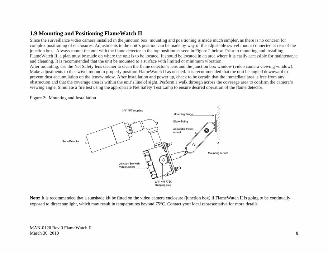
1.9 Mounting and Positioning FlameWatch II Since the surveillance video camera installed in the junction box, mounting and positioning is made much simpler, as there is no concern for complex positioning of enclosures. Adjustments to the unit’s position can be made by way of the adjustable swivel mount connected at rear of the junction box. Always mount the unit with the flame detector in the top position as seen in Figure 2 below. Prior to mounting and installing FlameWatch II, a plan must be made on where the unit is to be located. It should be located in an area where it is easily accessible for maintenance and cleaning. It is recommended that the unit be mounted to a surface with limited or minimum vibration. After mounting, use the Net Safety lens cleaner to clean the flame detector’s lens and the junction box window (video camera viewing window). Make adjustments to the swivel mount to properly position FlameWatch II as needed. It is recommended that the unit be angled downward to prevent dust accumulation on the lens/window. After installation and power up, check to be certain that the immediate area is free from any obstruction and that the coverage area is within the unit’s line of sight. Perform a walk through across the coverage area to confirm the camera’s viewing angle. Simulate a fire test using the appropriate Net Safety Test Lamp to ensure desired operation of the flame detector. Figure 2: Mounting and Installation.
Note: It is recommended that a sunshade kit be fitted on the video camera enclosure (junction box) if FlameWatch II is going to be continually exposed to direct sunlight, which may result in temperatures beyond 75°C. Contact your local representative for more details.
MAN-0120 Rev 0 FlameWatch II March 30, 2010 9
SECTION 2: Operation
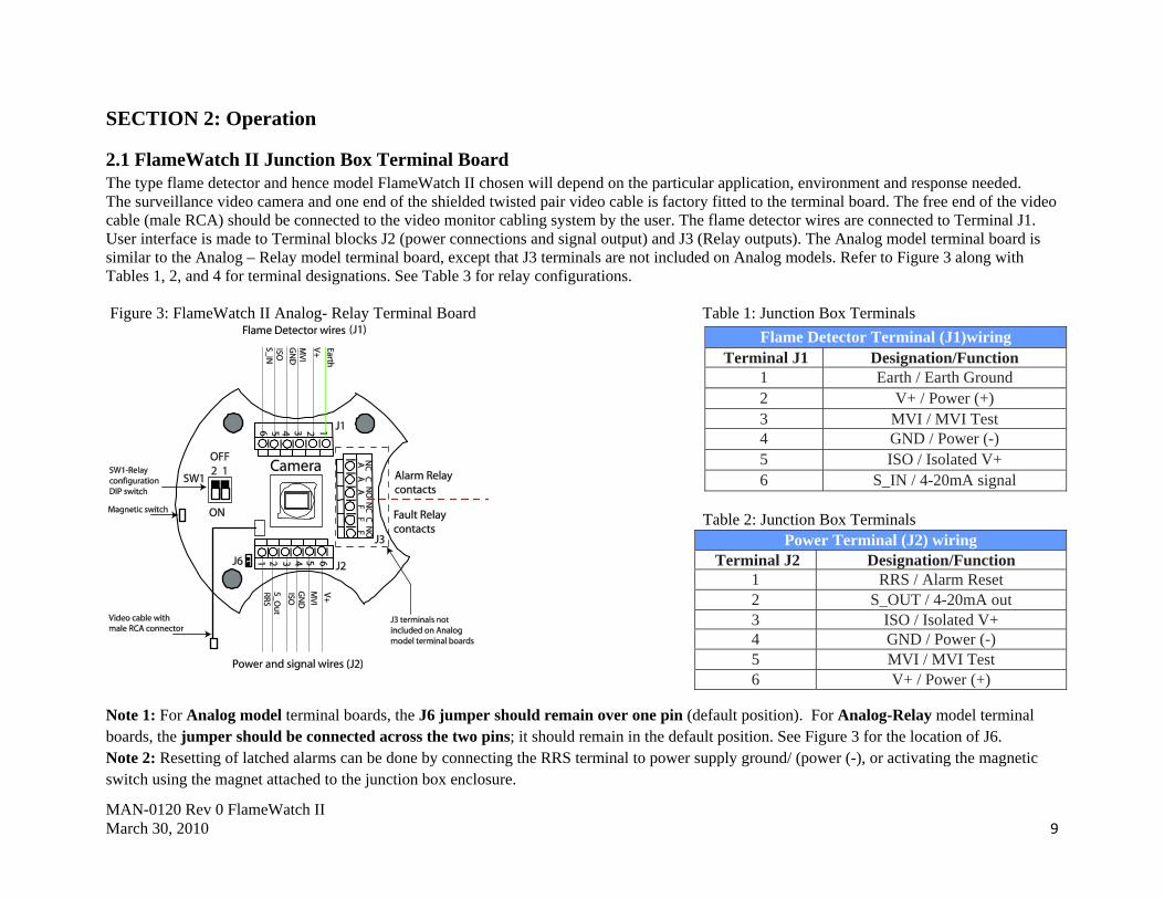
2.1 FlameWatch II Junction Box Terminal Board The type flame detector and hence model FlameWatch II chosen will depend on the particular application, environment and response needed. The surveillance video camera and one end of the shielded twisted pair video cable is factory fitted to the terminal board. The free end of the video cable (male RCA) should be connected to the video monitor cabling system by the user. The flame detector wires are connected to Terminal J1. User interface is made to Terminal blocks J2 (power connections and signal output) and J3 (Relay outputs). The Analog model terminal board is similar to the Analog – Relay model terminal board, except that J3 terminals are not included on Analog models. Refer to Figure 3 along with Tables 1, 2, and 4 for terminal designations. See Table 3 for relay configurations. Figure 3: FlameWatch II Analog- Relay Terminal Board Table 1: Junction Box Terminals
Table 2: Junction Box Terminals Note 1: For Analog model terminal boards, the J6 jumper should remain over one pin (default position). For Analog-Relay model terminal boards, the jumper should be connected across the two pins; it should remain in the default position. See Figure 3 for the location of J6. Note 2: Resetting of latched alarms can be done by connecting the RRS terminal to power supply ground/ (power (-), or activating the magnetic switch using the magnet attached to the junction box enclosure.
Flame Detector Terminal (J1)wiring Terminal J1 Designation/Function
1 Earth / Earth Ground 2 V+ / Power (+) 3 MVI / MVI Test 4 GND / Power (-) 5 ISO / Isolated V+ 6 S_IN / 4-20mA signal
Power Terminal (J2) wiring Terminal J2 Designation/Function
1 RRS / Alarm Reset 2 S_OUT / 4-20mA out 3 ISO / Isolated V+ 4 GND / Power (-) 5 MVI / MVI Test 6 V+ / Power (+)

MAN-0120 Rev 0 FlameWatch II March 30, 2010 10
2.2 Relay configurations DIP Switch (SW1) Positions FlameWatch II Terminal Board has a two position DIP Switch to define the Coil and Latch Status for the Fire Relay. Refer to Figure 3 and Table 3 for locating the DIP Switch (SW1) and for configuring relays. The default setting for the Fire Relay is normally De-energized/Non-latching. The Fault Relay is factory set to Normally Energized/Non-latching and cannot be modified.
Table 3: SW1 DIP Switch Positions
Table 4: SW1 DIP Switch Positions
Coil and Latch Status
Fire Relay Position 1 Position 2
De-Energized/Non-latching ON ON
Energized/Non-latching ON OFF
De-Energized/ Latching OFF ON
Energized/ Latching OFF OFF
Relay Terminal (J3)
Alarm Relay Alarm Relay Contacts Fault Relay Fault Relay Contacts
A NC Normally Closed F NC Normally Closed
A C Common F C Common
A NO Normally Open F NO Normally Open
Note: Relays are Form C SPDT rated 5 Amperes at 30VDC/250AC. Relays are dry contacts.
MAN-0120 Rev 0 FlameWatch II March 30, 2010 11
2.3 Current Loop power configurations The two current loop power configurations available for the FW2-IR3S-AR are the Non –Isolated power configuration and the Isolated power configuration. When using the Non-Isolated power configuration (Non-Isolated current loop), the current output jumper located on the IR3S Flame Detector electronics should remain in its default (INT) position for source. Also, ‘ISO’ on the power terminal side of the FlameWatch II terminal board is not used in this configuration. See Figure 4 and Figure 5. For the Isolated power configuration (Isolated current loop), the current output jumper on the IR3S Flame Detector electronics should be placed in the ‘EXT’ position. See the IR3S Flame Detector manual for locating the jumper. For this configuration a separate power supply should be used to supply +24VDC to ‘ISO’ on the power terminal side of the FlameWatch II terminal board. See Figure 4 and Figure 6. Note: The FW2-UV/IRS-AR and FW2-UVS-AR only allow Non-Isolated power configuration. Refer to Figure 7.
MAN-0120 Rev 0 FlameWatch II March 30, 2010 12
SECTION 3: Wiring diagrams
3.1 FW2-IR3S-AR Current Loop power block diagrams Warning The current output jumper on the IR3S Flame Detector electronics should remain in the ‘INT’ position for Non-Isolated configuration (source). For the remaining configurations, the jumper should be placed in the ‘EXT’ position. See IR3S manual for jumper location.
Figure 4: FW2-IR3S-AR current sink and source wiring.
MAN-0120 Rev 0 FlameWatch II March 30, 2010 13
3.2 Typical wiring diagrams The following drawings are typical ways in wiring the system using general wiring requirements. Consult qualified personnel on specific wiring requirements. Note that alarms are wired in parallel in the examples shown.
Figure 5: FW2-IR3S-AR Non-Isolated current output wiring diagram. Note: The current output jumper located on IR3S Flame Detector electronics should remain in the ‘INT’ position for this configuration.

MAN-0120 Rev 0 FlameWatch II March 30, 2010 14
Figure 6: FW2-IR3S-AR Isolated current output wiring diagram. Note: Place current output jumper located on IR3S Flame Detector electronics in the ‘EXT’ position for this configuration. Refer to IR3S-A Flame Detector manual for correct placement of current output jumper.

MAN-0120 Rev 0 FlameWatch II March 30, 2010 15
Figure 7: FW2-UV/IRS-AR & FW2-UVS-AR Non- Isolated current output wiring diagram.

MAN-0120 Rev 0 FlameWatch II March 30, 2010 16
SECTION 4: Maintenance Each type of flame detector performs an automatic visual integrity test on the optics to ensure there is no obstruction on or near the detectors lens. Though this test is done, it is important to perform routine maintenance checks and cleaning of the detector lens and the junction box window. It is recommended that cleaning be done with Net Safety cleaning products. In addition to established maintenance routines, perform response tests on the detector by using the appropriate Net Safety Test Lamp to simulate fire conditions. Refer to specific flame detector and test lamp manuals when performing the above checks. Also do routine checks on the video camera to ensure area is not obstructed.
4.1 Troubleshoot If a problem should develop, carefully check for correct wiring and refer to individual product manuals. If it is determined that the problem is caused by an electronic defect, the device should be returned to the factory for repair. If returning equipment, see ‘How to Return Equipment’. Repairs to Net Safety products should not be performed in the field. Repairs to faulty or damaged equipment should only be performed at the factory; otherwise warranty on the product will be voided.
4.1.1 Spare Parts / Accessories Table 5: Available Spare Parts
Description Net Safety Part Number
Analog model IR3S Electronics IR3S-EMOD-A
Analog model UV./IRS Electronics UV/IRS-EMOD-A
Analog model UVS Electronics UVS-EMOD-A
Junction Box Electronics(Analog-relay) w/t camera (PAL) EMOD-0021
Junction Box Electronics(Analog-relay) w/t camera (NTSC) EMOD-0022
Junction Box Electronics(Analog) w/t camera (PAL) EMOD-0023
Junction Box Electronics(Analog) w/t camera (NTSC) EMOD-0024

MAN-0120 Rev 0 FlameWatch II March 30, 2010 17
HOW TO RETURN EQUIPMENT A Material Return Authorization number is required in order to return equipment. Please contact Net Safety Monitoring at (403) 219-0688 before returning equipment or consult our Service Department to possibly avoid returning equipment.
If you are required to return equipment, include the following information: 1. A Material Return Authorization number provided over the phone to you by Net Safety. 2. A detailed description of the problem. The more specific you are regarding the problem, the quicker our Service department can determine and resolve the problem. 3. A company name, contact name and telephone number. 4. A Purchase Order, from your company, authorizing repairs or request for quote. 5. Ship all equipment, prepaid to: Net Safety Monitoring Inc 2721 Hopewell Place NE Calgary, Alberta, Canada T1Y 7J7 6. Mark all packages: RETURN for REPAIR Waybills, for shipments from outside Canada, must state: Equipment being returned for repair All charges to be billed to the sender Also, please ensure a duplicate copy of the packing slip is enclosed inside the box indicating item 1-4 along with the courier and account number for returning the goods. All Equipment must be Shipped prepaid. Collect shipments will not be accepted. Pack items to protect them from damage and use anti-static bags or Aluminum- backed cardboard as protection from electrostatic discharge.

MAN-0120 Rev 0 FlameWatch II March 30, 2010 18
Appendix A: ELECTROSTATIC SENSITIVE DEVICE (ESD) Electrostatic discharge (ESD) is the transfer, between bodies, of an electrostatic charge caused by direct contact or induced by an electrostatic field. The most common cause of ESD is physical contact. Touching an object can cause a discharge of electrostatic energy—ESD! If the charge is sufficient and occurs near electronic components, it can damage or destroy those components. In some cases, damage is instantaneous and an immediate malfunction occurs. However, symptoms are not always immediate —performance may be marginal or seemingly normal for an indefinite period of time, followed by a sudden failure. To eliminate potential ESD damage, review the following guidelines: • Handle boards by metal shields—taking care not to touch electronic components. • Wear grounded wrist or foot straps, or ESD shoes or heel grounders to dissipate unwanted static energy. • Prior to handling boards, dispel any charge in your body or equipment. • Ensure components are transported and stored in static safe packaging. • When returning boards, carefully package in the original carton and static protective wrapping. • Ensure ALL personnel are educated and trained in ESD Control Procedures. In general, exercise accepted and proven precautions normally observed when handling electrostatic sensitive devices. A warning label is placed on the packaging, identifying product using electrostatic sensitive semiconductor devices.
MAN-0120 Rev 0 FlameWatch II March 30, 2010 19
Appendix B: RESISTANCE (OHMS)
Distance (Feet)
AWG #20 AWG #18 AWG #16 AWG #14 AWG #12 AWG #10 AWG #8
100 1.02 0.64 0.40 0.25 0.16 0.10 0.06
200 2.03 1.28 0.80 0.51 0.32 0.20 0.13
300 3.05 1.92 1.20 0.76 0.48 0.30 0.19
400 4.06 2.55 1.61 1.01 0.64 0.40 0.25
500 5.08 3.20 2.01 1.26 0.79 0.50 0.31
600 6.09 3.83 2.41 1.52 0.95 0.60 0.38
700 7.11 4.47 2.81 1.77 1.11 0.70 0.44
800 8.12 5.11 3.21 2.02 1.27 0.80 0.50
900 9.14 5.75 3.61 2.27 1.43 0.90 0.57
1000 10.20 6.39 4.02 2.53 1.59 1.09 0.63
1250 12.70 7.99 5.03 3.16 1.99 1.25 0.79
1500 15.20 9.58 6.02 3.79 2.38 1.50 0.94
1750 17.80 11.20 7.03 4.42 2.78 1.75 1.10
2000 20.30 12.80 8.03 5.05 3.18 2.00 1.26
2250 22.80 14.40 9.03 5.68 3.57 2.25 1.41
2500 25.40 16.00 10.00 6.31 3.97 2.50 1.57
3000 30.50 19.20 12.00 7.58 4.76 3.00 1.88
3500 35.50 22.40 14.10 8.84 5.56 3.50 2.21
4000 40.60 25.50 16.10 10.00 6.35 4.00 2.51
4500 45.70 28.70 18.10 11.40 7.15 4.50 2.82
5000 50.10 32.00 20.10 12.60 7.94 5.00 3.14

MAN-0120 Rev 0 FlameWatch II March 30, 2010 20
Distance (Feet)
AWG #20
AWG #18
AWG #16
AWG #14
AWG #12
AWG #10
AWG #8
5500 55.80 35.10 22.10 13.91 8.73 5.50 3.46
6000 61.00 38.30 24.10 15.20 9.53 6.00 3.77
6500 66.00 41.50 26.10 16.40 10.30 6.50 4.08
7000 71.10 44.70 28.10 17.70 11.10 7.00 4.40
7500 76.10 47.90 30.10 19.00 12.00 7.49 4.71
8000 81.20 51.10 23.10 20.20 12.70 7.99 5.03
9000 91.40 57.50 36.10 22.70 14.30 8.99 5.65
10000 102.00 63.90 40.20 25.30 15.90 9.99 6.28 Note: Resistance is one way. This figure should be doubled when determining closed loop.
Appendix B: Resistance Table (cont’d)

MAN-0120 Rev 0 FlameWatch II March 30, 2010 21
Appendix C: Technical Specifications of Video Camera
Specification Video Camera Image Pick-up Device 1/3” Super HAD II CCD High Resolution
Pixel number NTSC=270K / PAL=320K(normal resolution), NTSC = 380K / PAL= 440K(High resolution) Effective Picture Elements NTSC:768*494, PAL: 752*582(H*V)
Horizontal Resolution 540 TV lines Minimum Illumination [email protected]
S/N Ratio More than 48 dB Auto Electronic shutter NTSC:1/60s ~ 1/100,000s, PAL:1/50s ~ 1/110,000s Gamma Characteristic 0.45
Gain control Automatically White Balance Automatically(2500K ~ 9500K)
Synchronous System Negative sync. Internal Video Output 1Vp-p composite video
Operating temperature -20°C to +70°C Field of View 100 degrees
Specification Junction Box Electronics Electrical rating Operating Voltage: 12 to 32 VDC
Power consumption At 24VDC: Nominal 135mA/3.24W Max 170mA/4.08W
Relay rating 5A@30VDC/250AC, Form C SPDT dry contacts Specification Junction Box
Metallurgy Aluminum (AL) or 316 SS Weight Aluminum: 0.8 Kg / 2.0 lbs (316 SS 1.6 Kg / 3.5lbs)
NEMA/IP IP6Iyjryj IP67ry
Approvals
Factory Mutual (FM) Approvals:
US (Certificate 3035217): XP/l/1/BCD/-55°C < +85°C; Type 4X, IP67 l/1/ AEx d IIB+H2 -55°C < Ta < +85°C ; Type 4X, IP67 Can: (Certificate 3035217C): XP/l/1/BCD/ -55°C <+85°C; Type 4X, IP67 I/1/ Ex d IIB+H2 -55°C < Ta < +85°C ; Type 4X, IP67
ATEX (Certificate FM09ATEX0027U) II 2 G Ex d IIB+H2 -55°C < Ta < +85°C ; IP67

MM
A
M
MAN-0120 Rev 0March 30, 2010
Appendix D:Models
Operating Voltage
Power Consumptio(@ 24Vdc)
Power Consumptio(@ 12Vdc)
In Rush Current (at 24Vdc)
Output
Field of View
Spectral Range
Time Delay
Sensitivity Settings
Temperature/ RH
Metallurgy & IP/NemRatings
Weight (with swive
Approvals
0 FlameWatch II
IR3S FlameIR3S‐A
e
n Nominal 30Maximum 6
n Nominal 45Maximum 1
0 to 20 mA – Inimpedance of 832Vdc or 150OhNon‐Isolated lo
FM Perfo
s
ma
el)
Performance ce
Clas(Canada ONLY
e Detector Te(Analog)
0mA/ 0.72W 64mA/ 1.44W
DE
5mA/ 0.60W 13mA/ 1.32W
DE
M
nto a max loop 800Ohms @ hms @ 11.0Vdc. oop supply
NSebo
ormance tested: 100°
70° horiz
FM Certified (‐40°C
ertified to: Class3260,
s I, Div 1, Grps BCD, Y – with special cemen
echnical Spec
1
De‐Energized: Nomnergized: Nominal
De‐Energized: Nomnergized: Nominal
Maximum‐ 165mA,
Up
Normally open/Normaelectable energized/ doth Fire & Fault relay
horizontal / 100° vert
zontal / 70° vertical at
The IR3S fire d
Two (2
to +75°C / ‐40°F to 16
Aluminum o
2.
ANSI/NEMA 250, an
T5. Ex d IIB+H2 T5.nting), BCD, T5. Ex d
cifications I3RS‐R (R
0 to 32 VDC measu
minal 39mA/0.96W. l‐ 51mA, =1.20w). M
minal‐ 66mA/0.84W.l‐ 93mA, =1.08w)
2.04W
to 2.6 A for 2.ms (var
ally closed contacts rade‐energized Fire relays fixed as non‐latchin
tical @ 50% of the on‐ainform
a distance of 200ft( N
detector measures at th
DIP switch selectable
2) adjustable setting v
67°F). Operational (‐5
or SS316 (factory seale
.1Kg /4.5lbs (SS316 Op
nd IEC60529.
Class I, Zone 1, Grpsd IIB+H2 T5.
Relay) ured at the detector
Maximum 73mA/ Maximum‐ 86mA, 2
Maximum‐ 138mA
ries with power suppl
ated for 5A @ 30Vdc/1ay. Fault relay fixed ang
axis detection distancmation.
Not FM Performance t
hree distinct Infrared
e 0, 3, 5, 10 seconds,
via DIP switch (High/
50°C to +75°C / ‐58°F
ed housing). IP66 and
ption @ 3.4Kg/ 7.5lbs)
s IIB+H2, T5; Nema 4X
r
1.68W 2.16W
A/ 1.68W
ly)
125Vac. as energized and
0 im1loR
ce for N‐Heptane. See
tested) See Table 3, M
Wavelengths
Low)
to 167°F). 0 – 95% R
d NEMA 4X
)
X, IP66. For CANAD
IR3S‐AD (Analo
Nominal 30mAMaximum 64mA
Nominal 45mAMaximum 113mA
to 20 mA – Into a mampedance of 800Ohm50Ohms @ 11.0Vdc. Noop supply. RS‐485 RTU Modbus pe Table 2, MAN‐0044f
MAN‐0044
RH non condensing
DA ONLY, Class I, Div
22
og/Digital)
A/ 0.72W A/ 1.44W
A/ 0.60W A/ 1.32W
ax loop ms @ 32Vdc or Non‐Isolated
protocol. or more
v 1, Grps A

MM
A
MAN-0120 Rev 0March 30, 2010
Appendix E: Models
Operating Voltage
Power Consumption
In Rush Current
Current Output
Relay Output
Field of View
Spectral Range
Time Delay
Sensitivity Settings
Temperature & RH
Metallurgy & IP/NEMA
Weight (with swive
Approvals
0 FlameWatch II
UV/IRS Fla
e
n
At 10Vdc: No*With Heater:
At 24Vdc: No*With Heater:
At 32Vdc: No*With Heater:
UV radiation ov
s
H
l)
FM Perform
Cla
me Detector UV/IRS‐
ominal 95mA/ 0.95W: Nominal 200mA/
ominal 45mA/ 1.1W: Nominal 90mA/ 2
ominal 35mA/ 1.12W: Nominal 70mA/ 2
0 to 20 mA – In
ver the range of 185 to
FM Certified (‐40°C
mance certified to: Cl
ass I, Div 1, Grps B,C,D
Technical Sp‐A (Analog)
W. Maximum 225m2.0W. Maximum 3
W. Maximum 115mA2.16W. Maximum 1
W. Maximum 105m2.24W. Maximum 1
nto a max loop imped
120° Horizo
o 260 nanometres (18
DIP sw
C to +75°C / ‐40°F to 1
Aluminum o
2
ass3260, ANSI/NEMA
D, T5. Ex d IIB+H2 T
pecifications
10 to 3
mA/ 2.25W345mA/ 3.45W
A/ 2.76W 165mA/ 3.96W
mA/ 3.36W 145mA/ 4.64W
1.5A fo
dance of 800Ohms @ 3
ontal, 95° Vertical @ 50
50 to 2600 angstroms
DIP switch selectab
witch selectable 8, 16,
67°F). Operational (‐
or SS316 (factory seal
2.1Kg /4.5lbs (SS316 O
A 250, and IEC60529.
T5. Class I, Zone 1, G
2 VDC
At 10Vdc: Nomin*With Heater: No
At 24Vdc: Nomin*With Heater: No At 32Vdc: Nomin*With Heater: No
or 22ms
32Vdc or 150Ohms @
Form C contacts raenergized, latchingnon‐latching
0% of maximum on ax
); IR radiation in the 4
ble 0, 3, 5, 7 seconds,
24 or 32 counts per se
‐50°C to +75°C / ‐58°F
ed housing). IP66 an
Option @ 3.4Kg/ 7.5lbs
rps IIB+H2 T5; Nema
UV/IRS‐AR (An
nal 95mA/ 0.95W. Mominal 200mA/ 2.0W
nal 45mA/ 1.1W. Mominal 90mA/ 2.16W
nal 35mA/ 1.12W. ominal 70mA/ 2.24W
11.0Vdc. Non‐Isolate
ted 1A @ 30Vdc, 0.5Ag/ non‐latching Fire re
xis distance.
4.4micron range
econds
F to 167°F). 0 – 95% R
nd NEMA 4X
s)
a 4X, IP66.
nalog/Relay)
Maximum 225mA/W. Maximum 335m
Maximum 115mA/ 2W. Maximum 165m
Maximum 105mA/W. Maximum 145m
ed loop supply
A @125Vac. Selectableelay. Fault relay fixed
RH non condensing
23
/ 2.25W mA/ 3.35W
2.76W mA/ 3.96W
/ 3.36W mA/ 4.64W
e energized/ de‐d as energized/
MM
A
MAN-0120 Rev 0March 30, 2010
Appendix F: Models
Operating Voltage
Power Consumptio
In Rush Current
Current Output
Relay Output
Field of View
Spectral Range
Time Delay
Sensitivity Settings
Temperature & RH
Metallurgy & IP/NEMA
Weight (with swive
Approvals
0 FlameWatch II
UVS Flame
e
n
At 10Vdc: No*With Heater
At 24Vdc: No*With Heater
At 32Vdc: No*With Heater
s
H
el)
FM Performanc
Class I, Div 1, G
Detector TecUVS‐A
ominal 95mA/ 0.95Wr: Nominal 200mA/
ominal 45mA/ 1.1Wr: Nominal 90mA/ 2
ominal 35mA / 1.12r: Nominal 70mA/ 2
0 to 20 mA –
FM Certified (‐40°
ce certified to: Class3
Grps B,C,D, T5. Ex d
chnical SpeciA (Analog)
W. Max 225mA/ 2.2.0W. Maximum 3
W. Max 115mA/ 2.72.16W. Maximum 1
2W. Max 105mA/ 32.24W. Maximum 1
Into a max loop impe
N/A
120° Horiz
UV radiation ove
DIP s
°C to +75°C / ‐40°F to
Aluminum
3260, ANSI/NEMA 25
d IIB+H2 T5. Class I, Z
ifications
10 to
25W 335mA/ 3.35W
76W 165mA/ 3.96W
3.36W 140mA/ 4.48W
1.5A f
edance of 800Ohms @
zontal, 95° Vertical @ 5
er the range of 185 to 2
DIP switches select
switch selectable 8, 16
167°F). Operational
m or SS316 (factory sea
2.1Kg /4.5lbs (SS316
50, IEC60529.
Zone 1, Grps IIB+H2 T
32 VDC
At 10Vdc: Nom*With Heater: N
At 24Vdc: Nom*With Heater: N
At 32Vdc: Nom*With Heater: N
for 22ms
@ 32Vdc or 150Ohms @
Form C contacts renergized, latchinnon‐latching
50% of maximum on
260 nanometres (1850
table 0, 3, 5, 7 seconds
6, 24 or 32 counts per
(‐50°C to +75°C / ‐58°
aled housing). IP66 a
Option @ 3.4Kg/ 7.5lb
T5; Nema 4X, IP66.
UVS‐AR (An
minal 95mA/ 0.95W. Nominal 200mA/ 2.0
minal 45mA/ 1.1W. Nominal 90mA/ 2.16
minal 35mA/ 1.12W. Nominal 70mA/ 2.24
@ 11.0Vdc. Non‐Isola
rated 1A @ 30Vdc, 0.5Ang/ non‐latching Fire r
axis distance.
0 to 2600 angstroms)
s.
seconds
°F to 167°F). 0 – 95%
nd NEMA 4X
bs)
nalog/Relay)
Max 225mA/ 2.25W0W. Maximum 335
Max 95mA/ 2.28W6W. Maximum 145
Max 80mA/ 2.56W4W. Maximum 115
ated loop supply
A @125Vac. Selectablrelay. Fault relay fixe
% RH non condensing
24
W 5mA/ 3.35W
5mA/ 3.48W
W 5mA/ 3.68W
le energized/ de‐ed as energized/

MAN-0120 Rev 0 FlameWatch II March 30, 2010 25
Net Safety Monitoring Inc. 2721 Hopewell Place NE, Calgary, AB Canada T1Y 7J7 1‐866‐FIREGAS (347‐3427) | ph. (403) 219‐0688 | fx. (403) 219‐0694 http://www.net‐safety.com | Email: nsmsales@net‐safety.com
PRODUCT SERVICES CONTACT INFORMATION Telephone [ 8am ‐ 5pm MDT ]: (403) 769‐6074 | (403) 717‐8219 Fax: (403) 219‐0694 Email: productservices@net‐safety.com http://www.net‐safety.com/service/product_services.html
Top Related