


Languages
Pages
Legal


1
Issue 6Fan Filter UnitsThe most advanced customized solutions for clean room technology – designed and produced from a single supplier.

2
Nicotra Gebhardt has defined their core compe tences:- Aerodynamics- Acoustics- Electrical motors- Control systems
Filter Fan Units made by Nicotra Gebhardt are available- as standard or customised versions- for standard and customised ceiling grids- for different filter and grid sizes- as top load or bottom load versions- for liquid or gasket seal systems- for various air flows and pressure drops- with minimal vibration and audible noise emissions- with an external rotor motor system- speed variation via BUS or supply voltage- for various control systemsEC-version- Internet/ Intranet access for controlling, monitoring and visualising- easy to install and set up with automatically addressed motor electronics- built-in power factor controller (PFC) for reactive current compensation- integrated self diagnosis and status messages- high operational reliability as the impeller runs on latest command after power drop or loss
Nicotra Gebhardt has developed control software to monitor different ventilating systems, room configurations and airflows.
Why should FFU’s be used in cleanrooms? Benefits which count …
... Redundancy With hundreds, or thousands of individual FFU’s in a facility, the loss of one or more units does not jeopardise the inte-grity of the room.
... Flexibility As the needs or uses change in a facility, the units can be exchanged with lay-in lights or blank panels. For facilities with lower classification, upgrades can be obtained by simply adding additional FFU’s. When a computer controlled management system is installed, units or clusters of units can be remote controlled to operational needs.
... Cost effective Use motors with the lowest power consumption available. With complete controllability of each and every FFU (via control and monitoring software) use just as much of power as necessary for your process.
... Negative plenum The negative plenum design draws recirculation air from the plenum itself. If there are any leaks, they migrate to the negative plenum and NOT the cleanroom.
... Salvageability FFU’s are fully salvageable as stand alone units.
Monitoring
Clean room processes call for the most advanced ventilation technologies that match to the specifications of the building infrastructure:
Choose your special requirements.
dimensions construction materials
sealing systems
volume and noise criteriapressure
motor performance
control and bus system
Please use the fax questi-onnaire inside this brochure and we will provide an offer that meets your needs.
Investment in laboratories and test facilities enable Nicotra Gebhardt to deal with the most sophisticated tasks in every area of the mentioned fields.

3
Filter Fan Units ar key elements in clean room ven-tilation systems. Nicotra Gebhardt supplies the elements for Filter Fan Units (FFU) as well as the units themselves. Starting from standard FFU de-sign, our team of experts imple-ments the specification for your special project.
Nicotra Gebhardt’s aerod ynamics research laboratories
have brought forth over 50 years of experience in leading-edge fan design and highly efficient technology.
Since the very beginning of the Nicotra Gebhardt com-pany the external rotor motor has been an essential element for driving fans. Nicotra Gebhardt has a manu-facturing facility for production of external rotor motors – the con-ventional asynchronous version and the electronically controlled brushless DC design. An expert team with special laboratories and test rigs is pushing this deve-lopment to new frontiers.
Fans
Motors
Casing
To guarantee a Running System join the power of your Convergence Company.
4
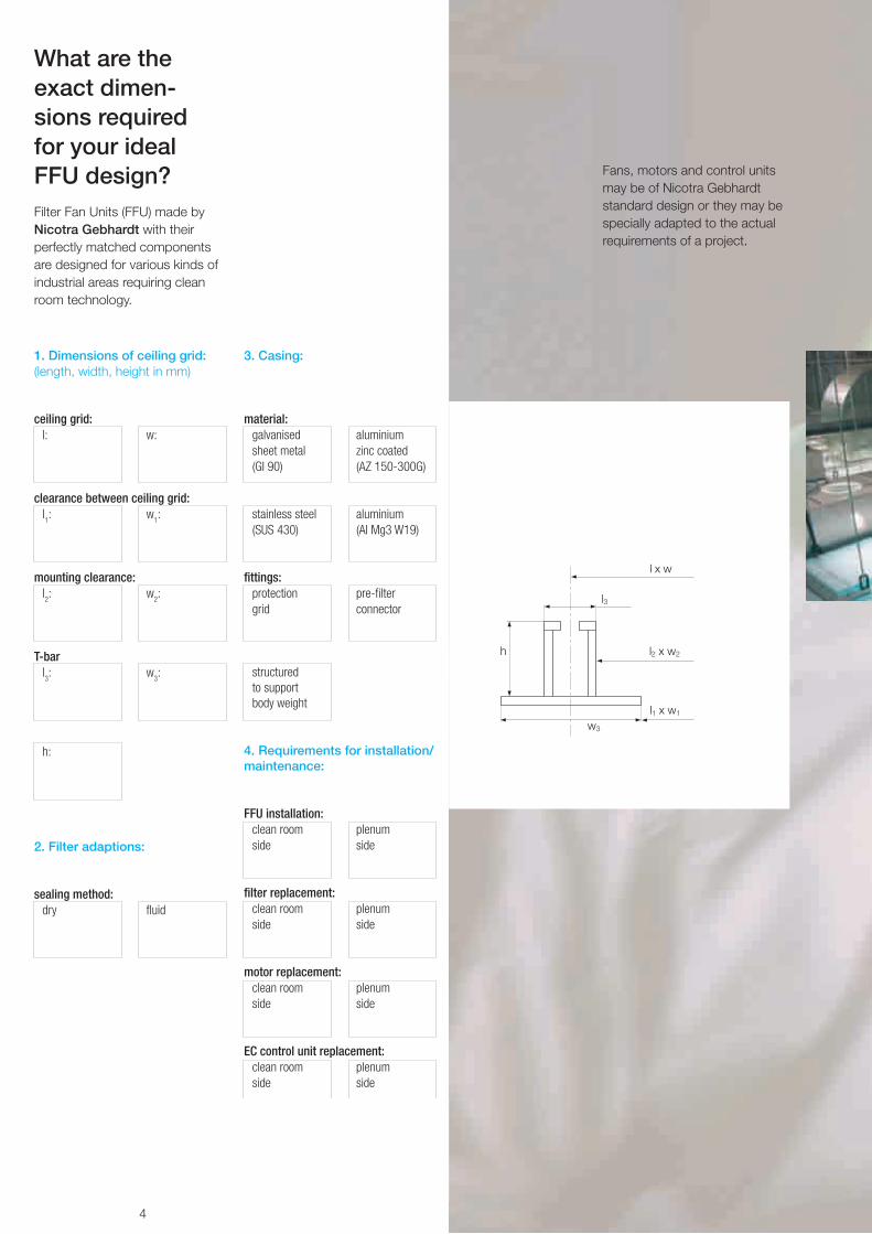
What are the exact dimen- sions required for your ideal FFU design?
1. Dimensions of ceiling grid:(length, width, height in mm)
ceiling grid:l: w:
clearance between ceiling grid:l1: w
1:
mounting clearance:l2: w
2:
T-barl3: w
3:
h:
2. Filter adaptions:
sealing method:dry fluid
3. Casing:
material:galvanised aluminium sheet metal zinc coated(GI 90) (AZ 150-300G)
stainless steel aluminium(SUS 430) (AI Mg3 W19)
fittings:protection pre-filtergrid connector
structured to support body weight
4. Requirements for installation/ maintenance:
FFU installation:clean room plenumside side
filter replacement:clean room plenumside side
motor replacement:clean room plenumside side
EC control unit replacement:clean room plenumside side
Fans, motors and control units may be of Nicotra Gebhardt standard design or they may be specially adapted to the actual require ments of a project.
Filter Fan Units (FFU) made by Nicotra Gebhardt with their perfectly matched components are designed for various kinds of industrial areas requiring clean room technology.

5
4’×4’ 3’×4’ 2’×4’ 2’×2’ 2.5’×5’
FFU 1200 × 1200 4’ × 4’ 1172 1172 400
FFU 900 × 1200 3’ × 4’ 872 1172 400
FFU 600 × 1200 2’ × 4’ 572 1172 400
FFU 750 × 1500 2.5’ × 5’ 720 1470 400
FFU 600 × 600 2’ × 2’ 534 534 350
example example minimum nominal grid sizes Wc [mm] Lc [mm] Hc [mm]
Main dimensions of the standard sizes
Using standard sizes to adapt for special building requirements
Casings
A system of standard sizes makes it possible – by com-bining them in different ways – to fill in every special shape of a building and, in this way, to create a filter fan ceiling, actively covered by the most effective filter fan units.
view from the plenum side
f: filter, c: casingOther dimensions to customer’s requirements
6
0
0.1
0.2
0.3
0.4
0.5
0.6
0 50 100 150 200Frequency
Vib
ratio
n ve
loci
ty
mm/s
Hz
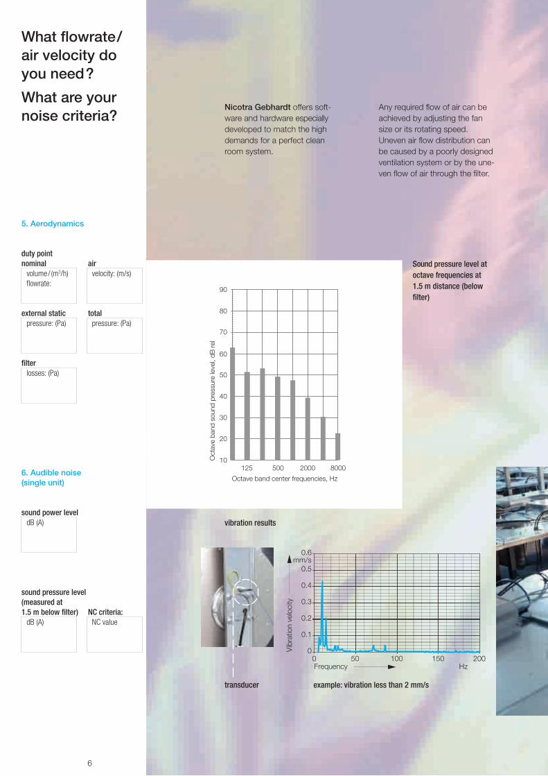
Nicotra Gebhardt offers soft-ware and hardware especially developed to match the high demands for a perfect clean room system.
What flowrate/ air velocity do you need?
What are your noise criteria?
Sound pressure level at octave frequencies at 1.5 m distance (below filter)
Any required flow of air can be achieved by adjusting the fan size or its rotating speed. Uneven air flow distribution can be caused by a poorly designed ventilation system or by the une-ven flow of air through the filter.
transducer
vibration results
5. Aerodynamics
duty pointnominal air
volume/ (m3/h) velocity: (m/s)flowrate:
external static totalpressure: (Pa) pressure: (Pa)
filter losses: (Pa)
6. Audible noise (single unit)
sound power leveldB (A)
sound pressure level (measured at 1.5 m below filter) NC criteria:
dB (A) NC value
example: vibration less than 2 mm/s
7
Fans
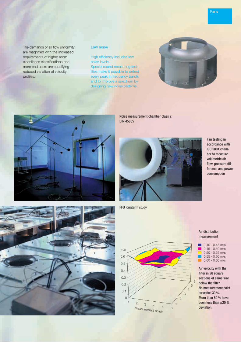
Noise measurement chamber class 2 DIN 45635
Fan testing in accordance with ISO 5801 cham-ber to measure volumetric air flow, pressure dif-ference and power consumption
The demands of air flow uniformity are magnified with the increased requirements of higher room cleanliness classifi cations and more end users are specifying reduced variation of velocity profiles.
FFU longterm study
Low noise
High efficiency includes low noise levels. Special sound measuring faci-lities make it possible to detect every peak in frequency bands and to improve a spectrum by designing new noise patterns.
Air distribution measurement
Air velocity with the filter in 36 square sections of same size below the filter. No measurement point exceeded 30 %. More than 80 % have been less than ±20 % deviation.

8
This design feature places the motor directly in the air stream and the cooling for the motor cannot be better.
External rotor motors integrate exceptionally well into a centrifu-gal fan impeller. They don’t take up extra space because they are entirely built in the impeller without creating ma-jor disturbances to the air stream through the impeller.
Asynchronous motor
- Established and proven tech-nology
- Not affected by external radio interference
- Individual speed easily and directly adjustable with voltage control unit
- Various possibilities (options) for control:
· Voltage control unit · Frequency converter
(BUS compatible) · Single phase AC converter · Single phase or 3-phases
power supply
Comparison of efficiencyAC-EC-unit with a power rating Pn= 200 W
7. Electrical requirements / power supply
7.1 Asynchronous
voltage:VAC 1-phase
VAC 3-phases
frequency:Hz
motor protection: PTC / Therm.Contact
What about the power supply?
Asynchronous motor
This type of motor is available as an AC motor, wound in such a way that speed control by simple voltage variation is possible. The motor is a standard and has been on the market for about 50 years.

9
Asynchro-nous motors
This allows the motor to operate more efficiently and therefore the motor size can be slightly smaller than that of a standard IEC motor.
High-voltage test rig
Automatic winding-machine
Nicotra Gebhardt motors comply with EN 60034-1 according to thermal class B resp. F. Motors for UL-FFUs in ac-cordance with UL 1004 resp. UL 2111, thermal class A.

10
- Outstanding efficiency because of permanent magnets
- High torque over a wide speed range
- High power factor (> 0.9)- Low harmonic distortion of
power supply current- Compact control device
EC motor
- High efficiency over wide range of speed
- BUS compatible- Independent of
mains frequency- Integrated speed control- Flexible in case of change in
installation situation
A drive unit consisting of an electronically commutated motor differs from the former DC mo-tors as there are no collector or carbon brushes.
These wearing components have been replaced in an elect-ronic commutated motor with maintenance-free electronics (control unit).
7.2 EC
voltage:VAC 1-phase
frequency:Hz
motor protection: electronicallymonitored
What about the electronics?
EC motor(Brushless DC motor)
The most advanced develop-ment is the EC motor which exploits the basic external rotor principle of a brushless DC motor.
11
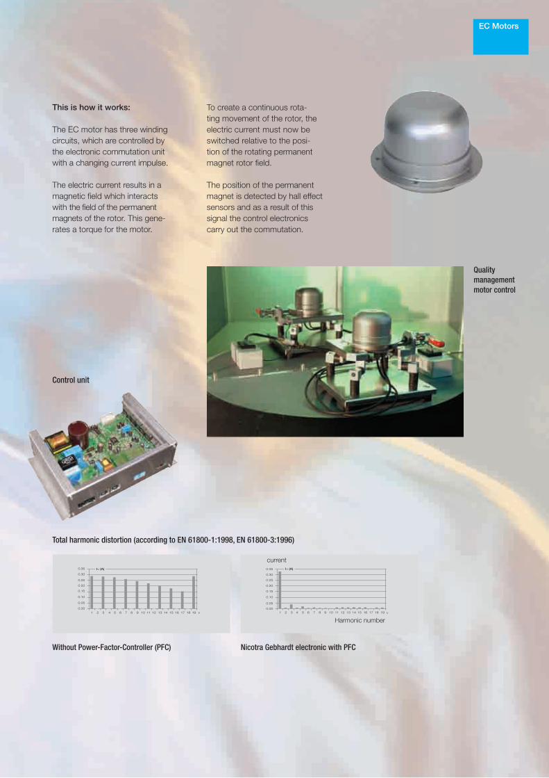
This is how it works:
The EC motor has three winding circuits, which are controlled by the electronic commutation unit with a changing current impulse. The electric current results in a magnetic field which interacts with the field of the permanent magnets of the rotor. This gene-rates a torque for the motor.
EC Motors
Control unit
To create a continuous rota-ting movement of the rotor, the electric current must now be switched relative to the posi-tion of the rotating permanent magnet rotor field. The position of the permanent magnet is detected by hall effect sensors and as a result of this signal the control electronics carry out the commutation.
Without Power-Factor-Controller (PFC) Nicotra Gebhardt electronic with PFC
Total harmonic distortion (according to EN 61800-1:1998, EN 61800-3:1996)
Quality managementmotor control
Harmonic number
current
12
LONWORKS® LAN-BUS
8. Control system
adjustable adjustable unit group
9. Controls
(analogue) (digital)voltage computerconverter controlled network
frequency converter
phase loop controller
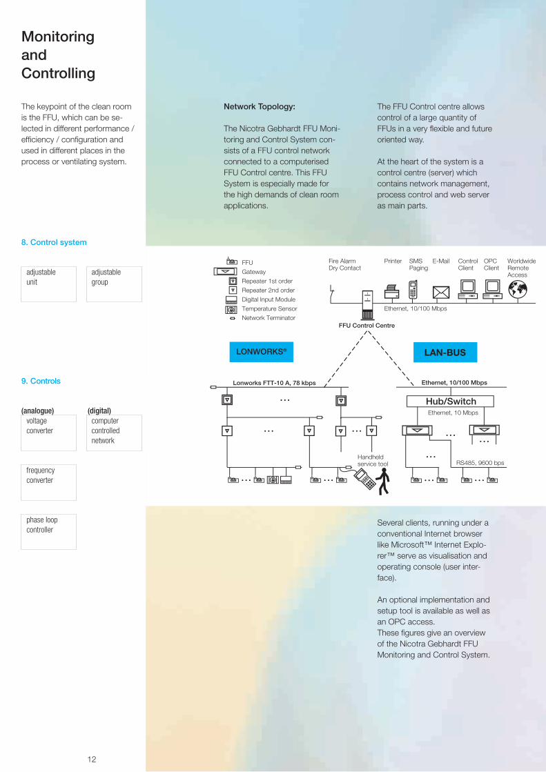
Network Topology:
The Nicotra Gebhardt FFU Moni-toring and Control System con-sists of a FFU control network connected to a computerised FFU Control centre. This FFU System is especially made for the high demands of clean room applications.
The FFU Control centre allows control of a large quantity of FFUs in a very flexible and future oriented way.
At the heart of the system is a control centre (server) which contains network management, process control and web server as main parts.
Several clients, running under a conventional Internet browser like Microsoft™ Internet Explo-rer™ serve as visualisation and operating console (user inter-face). An optional implementation and setup tool is available as well as an OPC access. These figures give an overview of the Nicotra Gebhardt FFU Monitoring and Control System.
The keypoint of the clean room is the FFU, which can be se-lected in different performance /efficiency / configuration and used in different places in the process or ventilating system.
Monitoring and Controlling
13
(24V DC Input)
Monitoring
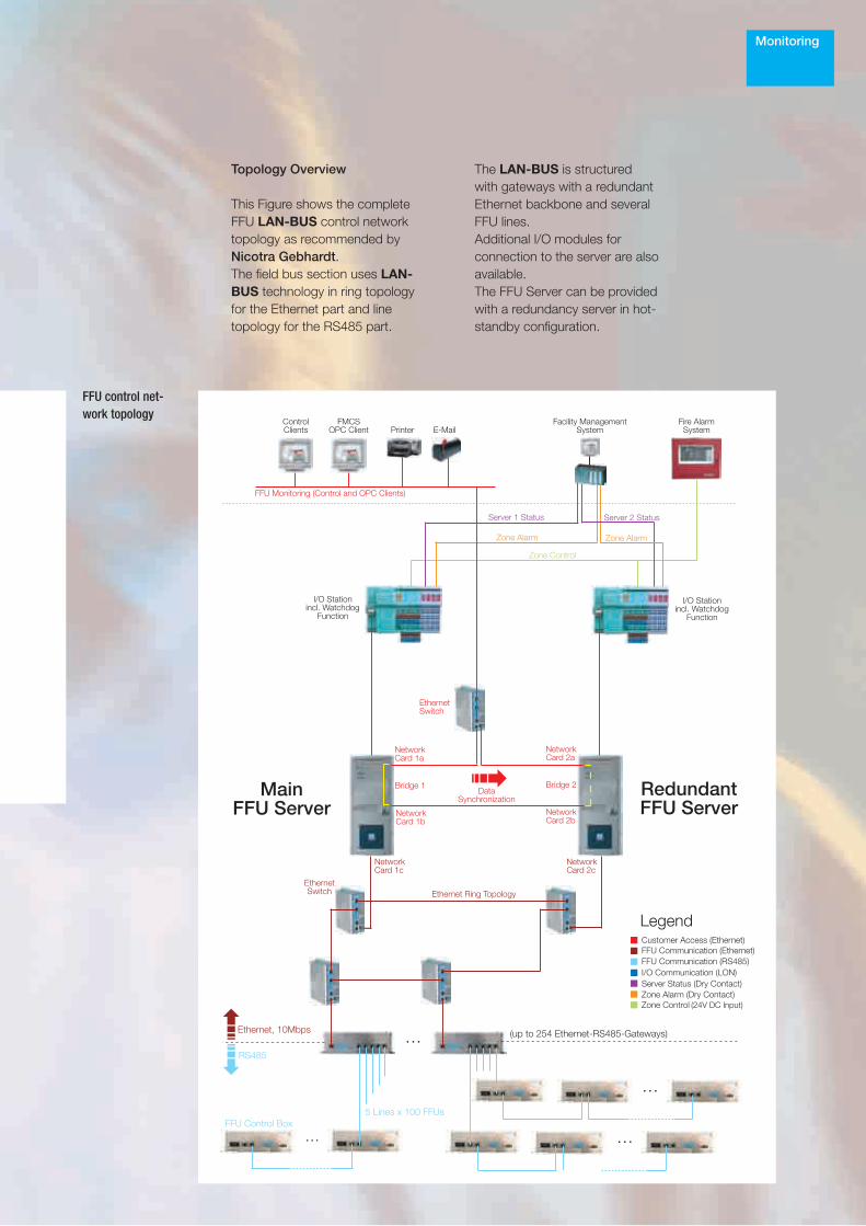
FFU control net-work topology
Topology Overview
This Figure shows the complete FFU LAN-BUS control network topology as recommended by Nicotra Gebhardt. The field bus section uses LAN-BUS technology in ring topology for the Ethernet part and line topology for the RS485 part.
The LAN-BUS is structured with gateways with a redundant Ethernet backbone and several FFU lines. Additional I/O modules for connection to the server are also available. The FFU Server can be provided with a redundancy server in hot-standby configuration.

14
Benefits of BUS-Systems
Zoom-in view with:· One FFU selected· Navigation tree· Control-Panel· Status-Panel
User interface overview showing:· Main plan with background picture· Icons for FFUs, digital input and tempe-
rature sensor· Navigation tree
User interface:· Example for background picture with a
large amount of FFUsSoftware & controlling
- Ethernet, IP network, HTTP protocol, HTML/XML, Internet Browsers (MicrosoftTM Internet ExplorerTM)
- Registration of each FFU run time for preventive filter main-tenance
- Remote maintenance and configuration via Internet con-nection
- Freely programmable time scheduler for automated FFU control (speed-up or speed-down of single FFUs or groups)
- Event logging (status- and change logfile)
Advantages of LONWORKS® based system
- Fast single command response- Fast single error response- FFU calibration from cleanroom- Handheld service tool- Free network topology- Digital input modules available- Temperature sensors available- Extensible system- Using of 3rd party components
(compatible with Nicotra Gebhardt specification)
Advantages of
LAN-BUSbased system
- Low system cost- Easy and fast commissioning
at jobsite- Fast multiple command re-
sponse- Fast multiple error response- Complete project engineering
and programming at design phase
- Low effort for components change
General Advantages- Analog interface available for
using without network system (0-5 V, 0-10 V, nmin, nmax,
error contact) - Modular structure of controller
allows easy change of interface type
Monitoring

15
Compare one system to the other
System Features LONWORKS® LAN-BUS
HardwareFFU Server PC + +User client local or remote via Ethernet + +Multiple clients + +Network topology Free Topology Line TopologyBackbone FTT-10A EthernetField Bus FTT-10A RS485Physical Repeater/Ethernet Gateway 2 or 3 way1 5 lines2
Nodes per Segment 60 100Maximum number of FFUs at the network 32,000 127,000Network Terminator + not needed8 Digital Input Module + -Digital I/0 Station + +Temperature Sensor Module + -Handheld Service Tool + not needed
CommunicationCommunication Principle Multi-Master Master-SlaveHeartbeat (Send-On-Change) +3 -Polling +4 +5
Addressing Neuron-ID6 Hardware7
Server SoftwareImport FFUs8 + +FFUs organized in building structures + +Free definable FFU groups + +2 control modes (% of Maxspeed, Air Speed) + +Integrated scheduler9 + +3 different FFU error priorities + +FFU runtime counter + +Digital input event handler + +Handling of temperature sensors + -Global emergency input10 + +Printing of error messages + +eMailing, Paging, SMS11 + +Log files (Error, Change, Speed Logs) + +OPC Server12 + +
User Interface (Client)User management with graduated authorisation13 + +Optimized for MICROSOFT® Internet Explorer® + +Colours and operator rights customizable + +Background drawing for each structure element + +Project navigation tree + +Alarm sound customizable + +Help function + +
1 can drive 1 or 2 segments with 60 nodes each 2 can drive 5 lines with 100 nodes each 3 in case of error, speed change and time-out 4 only if no heartbeat could be received by the server 5 parallel polling of max. 500 FFUs by each gateway 6 subnet/node addressing after FFU installation 7 node address set by hardware switch 8 from MICROSOFT® EXCEL® *.csv format 9 weekly programmable (start, stop, set speed)10 one dry contact, configurable functions: "Shutdown All FFUs" or "Display Only"11 external service provider required12 optional13 "Viewer", "Operator" and "Administrator"
Monitoring

16
The device offers easy commis-sioning and operating assisted by a clear menu structure and the single control element. Additional features like an auto-matic day/night shift (controlled by external input or by included clock), 3-level operator rights and non-volatile error storage downloadable to a PC make the FANCommander 200 a smart monitoring and control solution for small fan systems.
PropertiesFan control and parametrization - Single, groups, line, total of up to 200 fansAddressing - GBus-Fan address 0…99 at 2 lines R 200 FansDisplay - lighted LCD: 4 lines, 20 charactersControl elements - One element (turn and push button)Operation and navigation - Menu controlledFan parameter control - Day speed
- Night speed - ON/OFF - Maximum speed - Restart delay - Wink function - Reset errors
Error handling - non-volatile error storage - download error storage to PC (serial interface) - separate error indication of: - present errors - new (unconfirmed) errors - error indication by: - Display - LED - dry contact output
Automatic day/night shift - external control (24V DC input) - internal control (clock controlled)
Additional features - Internal clock - automatic fan registration (scan function) - UL-Listed (UL 508C)
Supply voltage - 115/230V AC
FANCommander 200
The FANCommander 200 is a stand-alone monitoring and con-trol unit for up to 200 fans. Fans can be controlled and monitored individually or by groups.
How would you like to control your FFUs?
17
Fan Filter Unit
15DZ
File E235903 UL507
This makes the FFU system (EC motors) offered by Nicotra Gebhardt so attrac-tive:
- Only 1 person for implementing or maintenance needed
- Client and server run at one PC or at two separated PCs connected via Ethernet link
- Any desired number of FFUs can be handled
- Graduated authorisation levels ("view only", "operate" or "administration")
- Freely definable FFU groups (structural and logical groups)
- OPC option for master station access (WonderwareTM, Intel-lutionTM or other OPC capable clients)
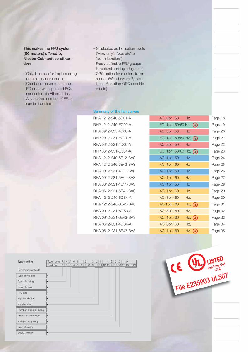
Summary of the fan curves
RHA 1212-240-6D01-A AC, 3ph, 50 Hz Page 18
RHP 1212-240-EC00-A EC, 1ph, 50/60 Hz, Page 19
RHA 0912-335-4D00-A AC, 3ph, 50 Hz Page 20
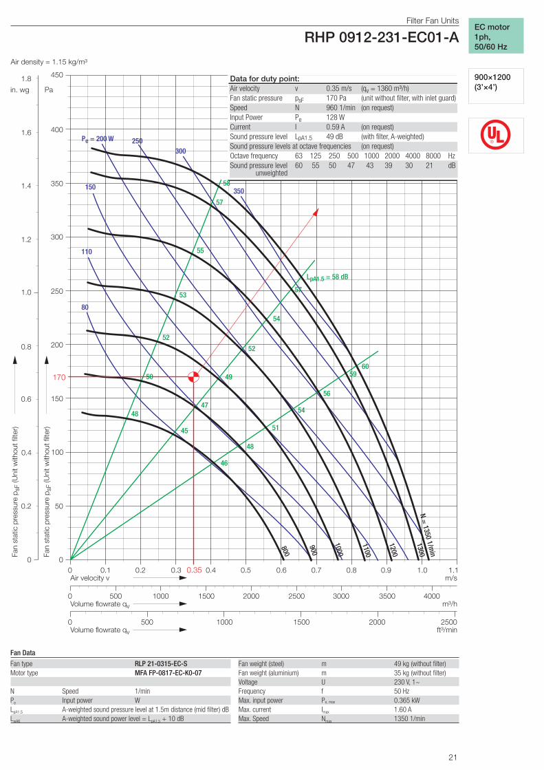
RHP 0912-231-EC01-A EC, 1ph, 50/60 Hz, Page 21
RHA 0612-331-4D00-A AC, 3ph, 50 Hz Page 22
RHP 0612-331-EC04-A EC, 1ph, 50/60 Hz, Page 23
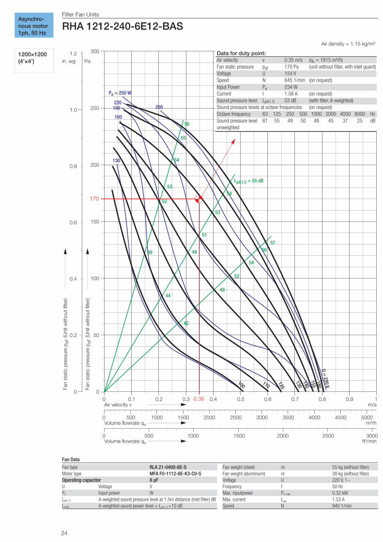
RHA 1212-240-6E12-BAS AC, 1ph, 50 Hz Page 24
RHA 1212-240-6E42-BAS AC, 1ph, 60 Hz Page 25
RHA 0912-231-4E11-BAS AC, 1ph, 50 Hz Page 26
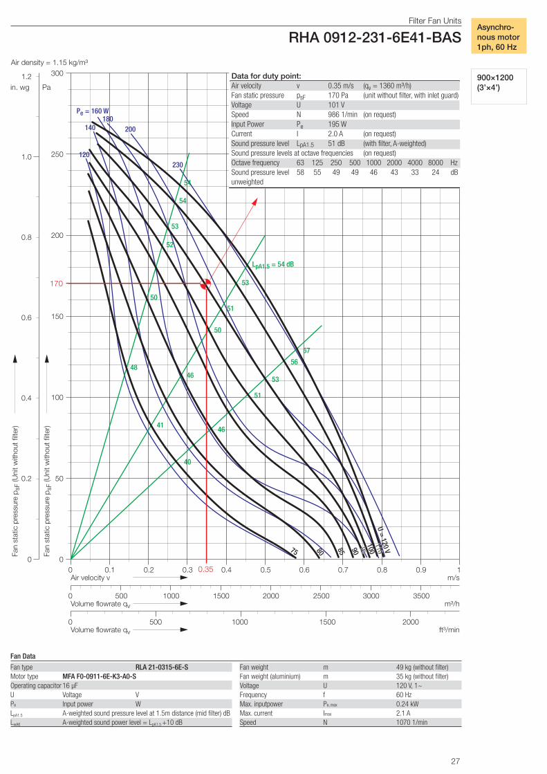
RHA 0912-231-6E41-BAS AC, 1ph, 60 Hz Page 27
RHA 0612-331-4E11-BAS AC, 1ph, 50 Hz Page 28
RHA 0612-231-6E41-BAS AC, 1ph, 60 Hz Page 29
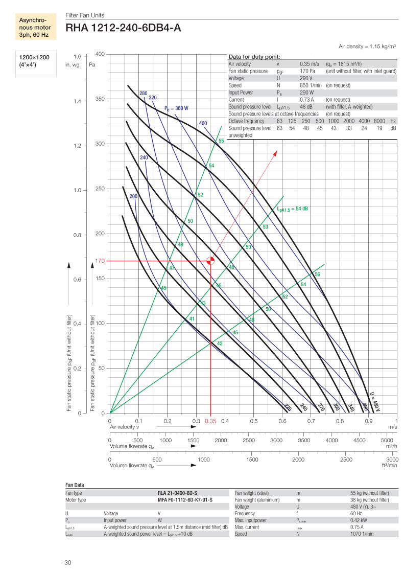
RHA 1212-240-6DB4-A AC, 3ph, 60 Hz, Page 30
RHA 1212-240-6E45-BAS AC.1ph, 60 Hz, Page 31
RHA 0912-231-6DB3-A AC, 3ph, 60 Hz, Page 32
RHA 0912-231-6E43-BAS AC, 1ph, 60 Hz, Page 33
RHA 0612-331-4DB4-A AC, 3ph, 60 Hz, Page 34
RHA 0612-231-6E43-BAS AC, 1ph, 60 Hz, Page 35

18
Filter Fan Units RHA 1212-240-6D01-A
Air density = 1.15 kg/m³
0
50
100
150
200
250
0 0.1 0.2 0.3 0.4 0.5 0.6 0.7 0.8 0.9 1 Air velocity v
Pa
Fan
stat
ic p
ress
ure
p sF
(Uni
t with
out f
ilter
)
m/s
0 1000 2000 3000 4000 5000 Volume flowrate qv m³/h
0 1000 1500 2000 2500 3000 Volume flowrate qv ft³/min
500
500 1500 2500 3500 4500
300
0
0.2
0.4
0.6
0.8
1.0
in. wg Fa
n st
atic
pre
ssur
e p s
F (U
nit w
ithou
t filt
er)
1.2 Data for duty point:Air velocity v 0.35 m/s (qv = 1815 m³/h)Fan static pressure psF 170 Pa (unit without filter, with inlet guard)Voltage U 251 V Speed N 846 1/min (on request)Input Power Pe 215 W Current I 0.65 A (on request)Sound pressure level LpA1.5 47 dB (with filter, A-weighted)Sound pressure levels at octave frequencies (on request)Octave frequency 63 125 250 500 1000 2000 4000 8000 HzSound pressure level 64 54 47 45 43 34 25 18 dBunweighted
280
210
190
Pe = 240 W
170
140 50
49
47
46
44
52
LpA1.5 = 50 dB
46
45
43
40
50
49
47
44
41
52
48
U = 400 V
280
230
200
150 170
170
0.35
Filter Fan Units
RHA 1212-240-6D01-A
1200×1200 (4’×4’)
Fan Data
Asynchro-nous motor3ph, 50Hz
Fan type RLA 21-0400-6D-SMotor type MFA F0-1112-6D-K3-00
U Voltage VPe Input power WLpA1.5 A-weighted sound pressure level at 1.5m distance (mid filter) dBLwA6 A-weighted sound power level = LpA1.5 + 10 dB
Fan weight (steel) m 55 kg (without filter)Fan weight (aluminium) m 38 kg (without filter)Voltage U 400 V (Y), 3~Frequency f 50 HzMax. input power Pe, max 0.29 kWMax. current Imax 0.85 ASpeed N 940 1/min

19
Air density = 1.15 kg/m³
Filter Fan Units
RHP 1212-240-EC00-A
0 0 0.1 0.2 0.3 0.4 0.5 0.6 0.7 0.8 0.9 1 Air velocity v
Pa
Fan
stat
ic p
r ess
u r e
p sF
(Uni
t with
out f
ilter
)
m/s
0 1000 2000 3000 4000 5000 V olume flowrate q v m³/h
0 1000 1500 2000 2500 3000 V olume flowrate q v ft³/min
500
500 1500 2500 3500 4500
50
100
150
200
250
300
350
400
0
in. wg
Fan
stat
ic p
r ess
u r e
p sF
(Uni
t with
out f
ilter
)
0.2
0.4
0.6
0.8
1.0
1.2
1.4
1.6 Data for duty point: Air velocity v 0.35 m/s ( q v = 1815 m³/h) Fan st a tic pressure p sF 170 Pa (unit without filte r , with inlet guard ) Speed N 847 1/min (on request) Input Power P e 173 WCurrent I 0.78 A (on request) Sound pressure level L pA1.5 48 dB (with filte r , A-weighted ) Sound pressure levels a t oct a ve frequencies (on request ) Oct a ve frequency 63 125 250 500 1000 2000 4000 8000 H z Sound pressure level 65 54 46 45 44 38 29 22 dB unweighted
350
300 250 P e = 200 W
150
55
53
50
47
L pA1.5 = 56 dB
54
50
47
57
55
52
49
N = 1070 1/min
1000
900
800
170
0.35
45
41
38
44
4540
4137
38
100
50
700
600
500
®
Filter Fan Units
RHP 1212-240-EC00-A
1200×1200 (4’×4’)
Fan Data - - - = speed limit for UL-version
EC motor1ph, 50/60 Hz
Fan type RLP 21-0400-ECMotor type MFA FP-0817-EC-K0-02
N Speed 1/minPe Input power WLpA1.5 A-weighted sound pressure level at 1.5m distance (mid filter) dBLwA6 A-weighted sound power level = LpA1.5 + 10 dB
Fan weight (steel) m 55 kg (without filter)Fan weight (aluminium) m 38 kg (without filter)Voltage U 230 V, 1~Frequency f 50 HzMax. input power Pe, max 0.37 kWMax. current Imax 1.62 AMax. speed Nmax 1070 1/min
20
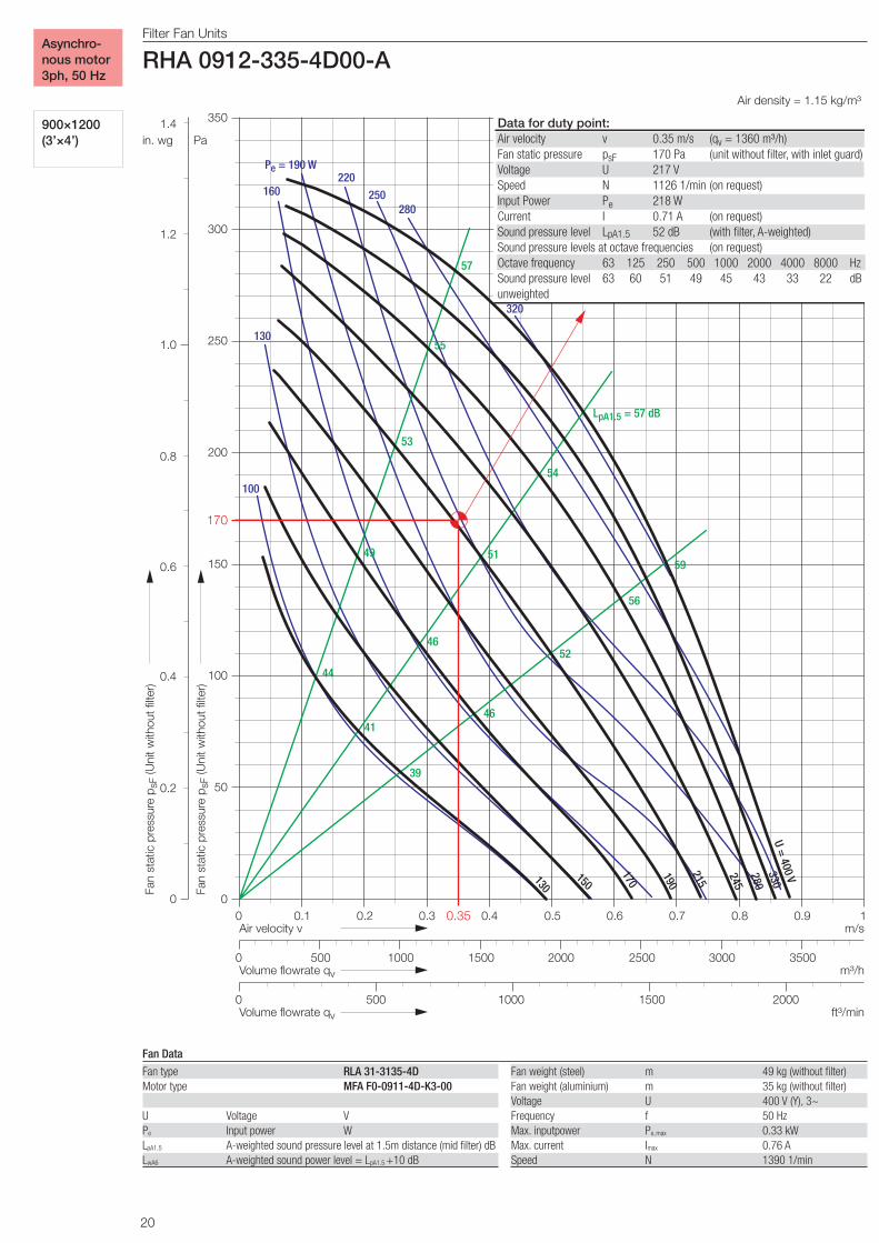
Filter Fan Units RHA 0912-335-4D00-A
Air density = 1.15 kg/m³
0
50
100
150
200
250
0 0.1 0.2 0.3 0.4 0.5 0.6 0.7 0.8 0.9 1 Air velocity v
Pa
Fan
stat
ic p
ress
ure
p sF
(Uni
t with
out f
ilter
)
m/s
0 1000 2000 3000 Volume flowrate qv m³/h
0 1000 1500 2000 Volume flowrate qv ft³/min
500
500 1500 2500 3500
300
350
0
0.2
0.4
0.6
0.8
1.0
in. wg Fa
n st
atic
pre
ssur
e p s
F (U
nit w
ithou
t filt
er)
1.2
1.4
Data for duty point:Air velocity v 0.35 m/s (qv = 1360 m³/h) Fan static pressure psF 170 Pa (unit without filter, with inlet guard)Voltage U 217 V Speed N 1126 1/min (on request) Input Power Pe 218 W Current I 0.71 A (on request) Sound pressure level LpA1.5 52 dB (with filter, A-weighted) Sound pressure levels at octave frequencies (on request) Octave frequency 63 125 250 500 1000 2000 4000 8000 HzSound pressure level 63 60 51 49 45 43 33 22 dBunweighted
320
280 250
220 Pe = 190 W
160
130
100
57
55
53
49
44
LpA1.5 = 57 dB
54
51
46
41
59
56
52
46
39
U = 400 V
330
280
245
215
190
150
170
130
170
0.35
Filter Fan Units
RHA 0912-335-4D00-A
900×1200 (3’×4’)
Asynchro-nous motor3ph, 50 Hz
Fan weight (steel) m 49 kg (without filter)Fan weight (aluminium) m 35 kg (without filter)Voltage U 400 V (Y), 3~Frequency f 50 HzMax. inputpower Pe,max 0.33 kWMax. current Imax 0.76 ASpeed N 1390 1/min
Fan type RLA 31-3135-4DMotor type MFA F0-0911-4D-K3-00
U Voltage VPe Input power WLpA1.5 A-weighted sound pressure level at 1.5m distance (mid filter) dBLwA6 A-weighted sound power level = LpA1.5
+10 dB
Fan Data
21
®
Air density = 1.15 kg/m³
Filter Fan Units
RHP 0912-231-EC01-A
00 0.1 0.2 0.3 0.4 0.5 0.6 0.7 0.8 0.9 1.0Air velocity v
Pa
Fan
stat
ic p
ress
ure
p sF
(Uni
t with
out f
ilter
)
m/s
50
100
150
200
250
300
350
450
0
in. wg
Fan
stat
ic p
ress
ure
p sF
(Uni
t with
out f
ilter
)
0.2
0.4
0.6
0.8
1.0
1.2
1.4
1.8
0 1000 2000 3000Volume flowrate qv m³/h
0 1000 1500 2000Volume flowrate qv ft³/min
500
500 1500 2500 3500
4001.6
2500
4000
1.1
Data for duty point:Air velocity v 0.35 m/s (qv = 1360 m³/h)Fan static pressure psF 170 Pa (unit without filter, with inlet guard)Speed N 960 1/min (on request)Input Power Pe 128 WCurrent I 0.59 A (on request)Sound pressure level LpA1.5 49 dB (with filter, A-weighted)Sound pressure levels at octave frequencies (on request)Octave frequency 63 125 250 500 1000 2000 4000 8000 HzSound pressure level 60 55 50 47 43 39 30 21 dB
unweighted
250
150
110
80
300
57
55
53
52
50
48
LpA1.5 = 58 dB
54
52
49
47
45
59
56
54
51
48
46
N = 1350 1/min
1200
1100
1000
900
800
170
0.35
Pe = 200 W
57
1300
35058
60
Filter Fan Units
RHP 0912-231-EC01-A
900×1200 (3’×4’)
EC motor1ph,50/60 Hz
Fan Data
Fan type RLP 21-0315-EC-SMotor type MFA FP-0817-EC-K0-07
N Speed 1/minPe Input power WLpA1.5 A-weighted sound pressure level at 1.5m distance (mid filter) dBLwA6 A-weighted sound power level = LpA1.5 + 10 dB
Fan weight (steel) m 49 kg (without filter)Fan weight (aluminium) m 35 kg (without filter)Voltage U 230 V, 1~Frequency f 50 HzMax. input power Pe, max 0.365 kWMax. current Imax 1.60 AMax. Speed Nmax 1350 1/min

22
Filter Fan Units RHA 0612-331-4D00-A
Air density = 1.15 kg/m³
0
50
100
150
200
250
0 0.1 0.2 0.3 0.4 0.5 0.6 0.7 0.8 0.9 1 Air velocity v
Pa
Fan
stat
ic p
ress
ure
p sF
(Uni
t with
out f
ilter
)
m/s
0 1000 2000 500 1500 2500 Volume flowrate qv m³/h
0 1000 1500 Volume flowrate qv ft³/min
500
300
0
0.2
0.4
0.6
0.8
1.0
in. wg Fa
n st
atic
pre
ssur
e p s
F (U
nit w
ithou
t filt
er)
1.2 Data for duty point:Air velocity v 0.35 m/s (qv = 910 m³/h) Fan static pressure psF 170 Pa (unit without filter, with inlet guard)Voltage U 268 V Speed N 1240 1/min (on request) Input Power Pe 128 W Current I 0.35 A (on request) Sound pressure level LpA1.5 47 dB (with filter, A-weighted) Sound pressure levels at octave frequencies (on request) Octave frequency 63 125 250 500 1000 2000 4000 8000 HzSound pressure level 61 58 48 45 38 35 29 21 dBunweighted 105
160
120 Pe = 140 W
90
70
51
50
49
48
46
44
LpA1.5 = 50 dB
48
47
45
43
41
52
51
49
46
44
40
U = 400 V
330
280
240
210
180
150
170
0.35
37
38
41
Filter Fan Units
RHA 0612-331-4D00-A
600×1200 (2’×4’)
Asynchro-nous motor3ph, 50 Hz
Fan weight (steel) m 43 kg (without filter)Fan weight (aluminium) m 32 kg (without filter)Voltage U 400 V (Y), 3~Frequency f 50 HzMax. inputpower Pe,max 0.19 kWMax. current Imax 0.44 ASpeed N 1340 1/min
Fan type RLA 31-2831-4DMotor type MFA F0-0810-4D-K3-01
U Voltage VPe Input power WLpA1.5 A-weighted sound pressure level at 1.5m distance (mid filter) dBLwA6 A-weighted sound power level = LpA1.5
+10 dB
Fan Data

23
®
Air density = 1.15 kg/m³
Filter Fan Units
RHP 0612-331-EC04-A
0
50
100
150
200
250
0 0.1 0.2 0.3 0.4 0.5 0.6 0.7 0.8 0.9 1 Air velocity v
Pa
Fan
stat
ic p
ress
ure
p sF
(Uni
t with
out f
ilter
)
m/s
m³/h
Volume flowrate qv ft³/min
300
350
450
1.1 1.2
0 1000 2000 3000
0 1000 1500 500
Volume flowrate qv
500 1500 2500
0
in. wg
Fan
stat
ic p
ress
ure
p sF
(Uni
t with
out f
ilter
)
0.2
0.4
0.6
0.8
1.0
1.2
1.4
1.8
1.6 400
Data for duty point:Air velocity v 0.35 m/s (qv = 910 m³/h) Fan static pressure psF 170 Pa (unit without filter, with inlet guard)Speed N 1213 1/min (on request) Input Power Pe 105 W Current I 0.48 A (on request) Sound pressure level LpA1.5 47 dB (with filter, A-weighted) Sound pressure levels at octave frequencies (on request) Octave frequency 63 125 250 500 1000 2000 4000 8000 HzSound pressure level 60 59 46 44 37 33 25 20 dB unweighted
Pe = 250 W
150
100
80
50
200
300
53
52
50
49
45
40
52
49
47
43
37
56
54
52
50
45
40
LpA1.5= 56 dB
54
54
48
42
39
42
46
48
57
N = 1750 1/min
1500
1400
1300
1200
1100
1000
900
1600
170
0.35
55
55
58
1700
Filter Fan Units
RHP 0612-331-EC04-A
600×1200 (2’×4’)
EC motor1ph,50/60 Hz
Fan type RLP 31-2831-EC-SMotor type MFA FP-0817-EC-K0-08
N Speed 1/minPe Input power WLpA1.5 A-weighted sound pressure level at 1.5m distance (mid filter) dBLwA6 A-weighted sound power level = LpA1.5 + 10 dB
Fan Data
Fan weight (steel) m 43 kg (without filter)Fan weight (aluminium) m 32 kg (without filter)Voltage U 230 V, 1~Frequency f 50 HzMax. input power Pe, max 0.33 kWMax. current Imax 1.45 AMax. Speed Nmax 1750 1/min
24
Filter Fan Units RHA 1212-240-6E12-BAS
Air density = 1.15 kg/m³
0
50
100
150
200
250
0 0.1 0.2 0.3 0.4 0.5 0.6 0.7 0.8 0.9 1 Air velocity v
Pa
Fan
stat
ic p
ress
ure
p sF
(Uni
t with
out f
ilter
)
m/s
300
0
0.2
0.4
0.6
0.8
1.0
in. wg Fa
n st
atic
pre
ssur
e p s
F (U
nit w
ithou
t filt
er)
1.2
0 1000 2000 3000 4000 5000 Volume flowrate qv m³/h
0 1000 1500 2000 2500 3000 Volume flowrate qv ft³/min
500
500 1500 2500 3500 4500
Data for duty point:Air velocity v 0.35 m/s (qv = 1815 m³/h) Fan static pressure psF 170 Pa (unit without filter, with inlet guard)Voltage U 154 V Speed N 845 1/min (on request) Input Power Pe 234 W Current I 1.56 A (on request) Sound pressure level LpA1.5 53 dB (with filter, A-weighted) Sound pressure levels at octave frequencies (on request) Octave frequency 63 125 250 500 1000 2000 4000 8000 HzSound pressure level 61 55 49 50 48 45 37 25 dBunweighted
280 220
190
Pe = 250 W
160
130
56
55
54
53
52
49
LpA1.5 = 55 dB
54
53
51
49
44
57 56
54
52
49
42
U = 220 V
180
155
140
130
120
110 100
170
0.35
Filter Fan Units
RHA 1212-240-6E12-BAS
1200×1200 (4’×4’)
Asynchro-nous motor1ph, 50 Hz
Fan Data
Fan weight (steel) m 55 kg (without filter)Fan weight (aluminium) m 38 kg (without filter)Voltage U 220 V, 1~Frequency f 50 HzMax. inputpower Pe,max 0.32 kWMax. current Imax 1.53 ASpeed N 940 1/min
Fan type RLA 21-0400-6E-SMotor type MFA F0-1112-6E-K3-C0-SOperating capacitor 8 µFU Voltage VPe Input power WLpA1.5 A-weighted sound pressure level at 1.5m distance (mid filter) dBLwA6 A-weighted sound power level = LpA1.5
+10 dB

25
Filter Fan Units RHA 1212-240-6E42-BAS
Air density = 1.15 kg/m³
0
50
100
150
200
250
0 0.1 0.2 0.3 0.4 0.5 0.6 0.7 0.8 0.9 1 Air velocity v
Pa
Fan
stat
ic p
ress
ure
p sF
(Uni
t with
out f
ilter
)
m/s
300
350
0
0.2
0.4
0.6
0.8
1.0
in. wg
Fan
stat
ic p
ress
ure
p sF
(Uni
t with
out f
ilter
)
1.2
1.4
0 1000 2000 3000 4000 5000 Volume flowrate qv m³/h
0 1000 1500 2000 2500 3000 Volume flowrate qv ft³/min
500
500 1500 2500 3500 4500
Data for duty point:Air velocity v 0.35 m/s (qv = 1815 m³/h) Fan static pressure psF 170 Pa (unit without filter, with inlet guard)Voltage U 108 V Speed N 842 1/min (on request) Input Power Pe 342 W Current I 3.3 A (on request) Sound pressure level LpA1.5 53 dB (with filter, A-weighted) Sound pressure levels at octave frequencies (on request) Octave frequency 63 125 250 500 1000 2000 4000 8000 HzSound pressure level 61 55 49 50 48 45 37 25 dBunweighted
400
Pe = 350 W 300
250
200
56
55
53
51
48
LpA1.5 = 55 dB
54
53
47
43
56
54
50
46
41
58 50
57
U = 120 V
115
110
105
100 90 95 80 75
85
170
0.35
Filter Fan Units
RHA 1212-240-6E42-BAS
1200×1200 (4’×4’)
Asynchro-nous motor, 1ph, 60 Hz
Fan Data
Fan weight (steel) m 55 kg (without filter)Fan weight (aluminium) m 38 kg (without filter)Voltage U 120 V, 1~Frequency f 60 HzMax. inputpower Pe,max 0.40 kWMax. current Imax 3.4 ASpeed N 950 1/min
Fan type RLA 21-0400-6E-SMotor type MFA F0-1112-6E-K3-A0-SOperating capacitor 20 µFU Voltage VPe Input power WLpA1.5 A-weighted sound pressure level at 1.5m distance (mid filter) dBLwA6 A-weighted sound power level = LpA1.5
+10 dB

26
Filter Fan Units RHA 0912-231-4E11-BAS
Air density = 1.15 kg/m³
0
50
100
150
200
250
0 0.1 0.2 0.3 0.4 0.5 0.6 0.7 0.8 0.9 1 Air velocity v
Pa
Fan
stat
ic p
ress
ure
p sF
(Uni
t with
out f
ilter
)
m/s
0 1000 2000 3000 Volume flowrate qv m³/h
0 1000 1500 2000 Volume flowrate qv ft³/min
500
500 1500 2500 3500
300
350
0
0.2
0.4
0.6
0.8
1.0
in. wg Fa
n st
atic
pre
ssur
e p s
F (U
nit w
ithou
t filt
er)
1.2
1.4
Data for duty point:Air velocity v 0.35 m/s (qv = 1360 m³/h) Fan static pressure psF 170 Pa (unit without filter, with inlet guard)Voltage U 193 V Speed N 976 1/min (on request) Input Power Pe 238 W Current I 1.25 A (on request) Sound pressure level LpA1.5 52 dB (with filter, A-weighted) Sound pressure levels at octave frequencies (on request) Octave frequency 63 125 250 500 1000 2000 4000 8000 HzSound pressure level 58 56 50 50 46 44 33 25 dBunweighted
220
Pe = 260 W
180
140
100
54
53
51
50
47
LpA1.5 = 54 dB
52
51
45
41
55
53
49
45
40
57 48
55
U = 220 V
205
190
180
170
150
160
130 120
140
170
0.35
Filter Fan Units
RHA 0912-231-4E11-BAS
900×1200 (3’×4’)
Asynchro-nous motor1ph, 50 Hz
Fan weight (steel) m 49 kg (without filter)Fan weight (aluminium) m 35 kg (without filter)Voltage U 220 V, 1~Frequency f 50 HzMax. inputpower Pe,max 0.30 kWMax. current Imax 1.37 ASpeed N 1060 1/min
Fan type RLA 21-0315-4E-SMotor type MFA F1-0911-4E-K3-C0-SOperating capacitor 6 µFU Voltage VPe Input power WLpA1.5 A-weighted sound pressure level at 1.5m distance (mid filter) dBLwA6 A-weighted sound power level = LpA1.5
+10 dB
Fan Data
27
Filter Fan Units RHA 0912-231-6E41-BAS
Air density = 1.15 kg/m³
0
50
100
150
200
250
0 0.1 0.2 0.3 0.4 0.5 0.6 0.7 0.8 0.9 1 Air velocity v
Pa
Fan
stat
ic p
ress
ure
p sF
(Uni
t with
out f
ilter
)
m/s
300
0
0.2
0.4
0.6
0.8
1.0
in. wg
Fan
stat
ic p
ress
ure
p sF
(Uni
t with
out f
ilter
)
1.2
0 1000 2000 3000 Volume flowrate qv m³/h
0 1000 1500 2000 Volume flowrate qv ft³/min
500
500 1500 2500 3500
Data for duty point:Air velocity v 0.35 m/s (qv = 1360 m³/h) Fan static pressure psF 170 Pa (unit without filter, with inlet guard)Voltage U 101 V Speed N 986 1/min (on request) Input Power Pe 195 W Current I 2.0 A (on request) Sound pressure level LpA1.5 51 dB (with filter, A-weighted) Sound pressure levels at octave frequencies (on request) Octave frequency 63 125 250 500 1000 2000 4000 8000 HzSound pressure level 58 55 49 49 46 43 33 24 dBunweighted
230
180 200
Pe = 160 W
140
120
54
54
53
52
50
48
LpA1.5 = 54 dB
53
51
50
46
41
57
56
53
51
46
40
U = 120 V
100
90
85
80
75
110
95
170
0.35
Filter Fan Units
RHA 0912-231-6E41-BAS
900×1200 (3’×4’)
Asynchro-nous motor1ph, 60 Hz
Fan weight m 49 kg (without filter)Fan weight (aluminium) m 35 kg (without filter)Voltage U 120 V, 1~Frequency f 60 HzMax. inputpower Pe,max 0.24 kWMax. current Imax 2.1 ASpeed N 1070 1/min
Fan type RLA 21-0315-6E-SMotor type MFA F0-0911-6E-K3-A0-SOperating capacitor 16 µFU Voltage VPe Input power WLpA1.5 A-weighted sound pressure level at 1.5m distance (mid filter) dBLwA6 A-weighted sound power level = LpA1.5
+10 dB
Fan Data

28
Filter Fan Units RHA 0612-331-4E11-BAS
Air density = 1.15 kg/m³
0
50
100
150
200
250
0 0.1 0.2 0.3 0.4 0.5 0.6 0.7 0.8 0.9 1 Air velocity v
Pa
Fan
stat
ic p
ress
ure
p sF
(Uni
t with
out f
ilter
)
m/s
0 1000 2000 500 1500 2500 Volume flowrate qv m³/h
0 1000 1500 Volume flowrate qv ft³/min
500
300
0
0.2
0.4
0.6
0.8
1.0
in. wg Fa
n st
atic
pre
ssur
e p s
F (U
nit w
ithou
t filt
er)
1.2 Data for duty point:Air velocity v 0.35 m/s (qv = 910 m³/h) Fan static pressure psF 170 Pa (unit without filter, with inlet guard)Voltage U 168 V Speed N 1237 1/min (on request) Input Power Pe 141 W Current I 0.87 A (on request) Sound pressure level LpA1.5 51 dB (with filter, A-weighted) Sound pressure levels at octave frequencies (on request) Octave frequency 63 125 250 500 1000 2000 4000 8000 HzSound pressure level 60 59 49 49 46 43 36 25 dBunweighted
180
160
Pe = 140 W
120
100
52
55
50
54
53
48
LpA1.5 = 54 dB
45
53
51
49
44
42
56
54
52
47
42
U = 220 V
175
160
150
140130120
190
170
0.35
54
45 50
47
44
39
Filter Fan Units
RHA 0612-331-4E11-BAS
600×1200 (2’×4’)
Asynchro-nous motor1ph, 50 Hz
Fan weight (steel) m 43 kg (without filterFan weight (aluminium) m 32 kg (without filter)Voltage U 220 V, 1~Frequency f 50 HzMax. inputpower Pe,max 0.19 kWMax. current Imax 0.90 ASpeed N 1340 1/min
Fan type RLA 31-2831-4E-SMotor type MFA F0-0908-4E-K3-C0-SOperating capacitor 4 µFU Voltage VPe Input power WLpA1.5 A-weighted sound pressure level at 1.5m distance (mid filter) dBLwA6 A-weighted sound power level = LpA1.5
+10 dB
Fan Data

29
Filter Fan Units RHA 0612-231-6E41-BAS
Air density = 1.15 kg/m³
0
50
100
150
200
250
Pa
Fan
stat
ic p
ress
ure
p sF
(Uni
t with
out f
ilter
)
300
0
0.2
0.4
0.6
0.8
1.0
in. wg
Fan
stat
ic p
ress
ure
p sF
(Uni
t with
out f
ilter
)
1.2
0 0.1 0.2 0.3 0.4 0.5 0.6 0.7 0.8 0.9 1 Air velocity v m/s
m³/h
Volume flowrate qv ft³/min
1.1 1.2
0 1000 2000 3000
0 1000 1500 500
Volume flowrate qv
500 1500 2500
Data for duty point:Air velocity v 0.35 m/s (qv = 910 m³/h) Fan static pressure psF 170 Pa (unit without filter, with inlet guard)Voltage U 108 V Speed N 922 1/min (on request) Input Power Pe 164 W Current I 1.56 A (on request) Sound pressure level LpA1.5 50 dB (with filter, A-weighted) Sound pressure levels at octave frequencies (on request) Octave frequency 63 125 250 500 1000 2000 4000 8000 HzSound pressure level 61 55 47 45 47 41 33 25 dBunweighted
200
180
160
Pe = 140 W 120
100 56
55
54
53
51
48
LpA1.5 = 51 dB
50
49
48
45
40
50
49
48
47
43
38
U = 120 V
110
105
95
90 85 80
115
100
170
0.35
Filter Fan Units
RHA 0612-231-6E41-BAS
600×1200 (2’×4’)
Asynchro-nous motor1ph, 60 Hz
Fan type RLA 21-0315-6E-SMotor type MFA F0-0908-6E-K3-A0-SOperating capacitor 12 µFU Voltage VPe
Input power WLpA1,5
A-weighted sound pressure level at 1.5m distance (mid filter) dBLwA6
A-weighted sound power level = LpA1.5 +10 dB
Fan Data
Fan weight (steel) m 43 kg (without filter)Fan weight (aluminium) m 32 kg (without filter)Voltage U 120 V, 1~Frequency f 60 HzMax. input power Pe, max 0.20 kWMax. current Imax 1.7 ASpeed N 940 1/min
30
Filter Fan Units RHA 1212-240-6DB4-A
Air density = 1.15 kg/m³
0
50
100
150
200
250
0 0.1 0.2 0.3 0.4 0.5 0.6 0.7 0.8 0.9 1 Air velocity v
Pa
Fan
stat
ic p
ress
ure
p sF
(Uni
t with
out f
ilter
)
m/s
300
350
0
0.2
0.4
0.6
0.8
1.0
in. wg Fa
n st
atic
pre
ssur
e p s
F (U
nit w
ithou
t filt
er)
1.2
1.4
0 1000 2000 3000 4000 5000 Volume flowrate qv m³/h
0 1000 1500 2000 2500 3000 Volume flowrate qv ft³/min
500
500 1500 2500 3500 4500
400 1.6
Data for duty point: Air velocity v 0.35 m/s (qv = 1815 m³/h) Fan static pressure psF 170 Pa (unit without filter, with inlet guard) Voltage U 290 V Speed N 850 1/min (on request) Input Power Pe 290 W Current I 0.73 A (on request) Sound pressure level LpA1.5 48 dB (with filter, A-weighted) Sound pressure levels at octave frequencies (on request) Octave frequency 63 125 250 500 1000 2000 4000 8000 Hz Sound pressure level 63 54 48 45 43 33 24 19 dB unweighted
400
Pe = 360 W
320 280
200
240
52
55
50
49
48
LpA1.5 = 54 dB
45
53
47
43
56
54
50
46
41
48
50
54
52
45
42
U = 480 V
400
340
300
240
270
220
170
0.35
Filter Fan Units
RHA 1212-240-6DB4-A
1200×1200 (4’×4’)
Asynchro-nous motor3ph, 60 Hz
Fan Data
Fan weight (steel) m 55 kg (without filter)Fan weight (aluminium) m 38 kg (without filter)Voltage U 480 V (Y), 3~Frequency f 60 HzMax. inputpower Pe,max 0.42 kWMax. current Imax 0.75 ASpeed N 1070 1/min
Fan type RLA 21-0400-6D-SMotor type MFA F0-1112-6D-K7-91-S
U Voltage VPe Input power WLpA1.5 A-weighted sound pressure level at 1.5m distance (mid filter) dBLwA6 A-weighted sound power level = LpA1.5
+10 dB
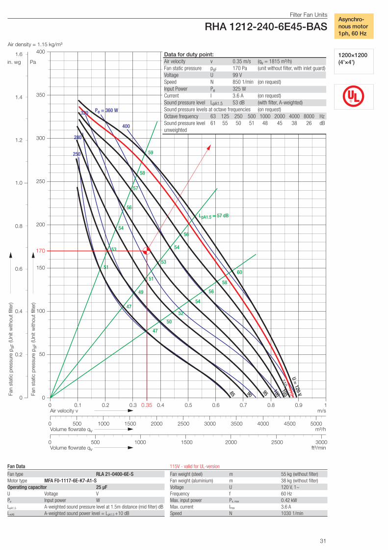
31
®
Filter Fan Units
RHA 1212-240-6E45-BASAir density = 1.15 kg/m³
0
50
100
150
200
250
0 0.1 0.2 0.3 0.4 0.5 0.6 0.7 0.8 0.9 1Air velocity v
Pa
Fan
stat
ic p
ress
ure
p sF
(Uni
t with
out f
ilter
)
m/s
300
350
0
0.2
0.4
0.6
0.8
1.0
in. wg
Fan
stat
ic p
ress
ure
p sF
(Uni
t with
out f
ilter
)
1.2
1.4
0 1000 2000 3000 4000 5000Volume flowrate qv m³/h
0 1000 1500 2000 2500 3000Volume flowrate qv ft³/min
500
500 1500 2500 3500 4500
4001.6 Data for duty point:Air velocity v 0.35 m/s (qv = 1815 m³/h) Fan static pressure psF 170 Pa (unit without filter, with inlet guard)Voltage U 99 V Speed N 850 1/min (on request) Input Power Pe 325 W Current I 3.6 A (on request) Sound pressure level LpA1.5 53 dB (with filter, A-weighted) Sound pressure levels at octave frequencies (on request) Octave frequency 63 125 250 500 1000 2000 4000 8000 HzSound pressure level 61 55 50 51 48 45 38 26 dBunweighted
400
Pe = 360 W320
280
250
57
58
56
54
52
LpA1.5 = 57 dB
5153
53
49
60
58
54
51
47
54
56
59
56
50
47
U = 120 V
115
110
100105959085
170
0.35
Filter Fan Units
RHA 1212-240-6E45-BAS
1200×1200 (4’×4’)
Asynchro-nous motor1ph, 60 Hz
Fan type RLA 21-0400-6E-SMotor type MFA F0-1117-6E-K7-A1-SOperating capacitor 25 µFU Voltage VPe
Input power WLpA1,5
A-weighted sound pressure level at 1.5m distance (mid filter) dBLwA6
A-weighted sound power level = LpA1.5 +10 dB
Fan Data 115V - valid for UL-version
Fan weight (steel) m 55 kg (without filter)Fan weight (aluminium) m 38 kg (without filter)Voltage U 120 V, 1~Frequency f 60 HzMax. input power Pe, max 0.42 kWMax. current Imax 3.6 ASpeed N 1030 1/min
32
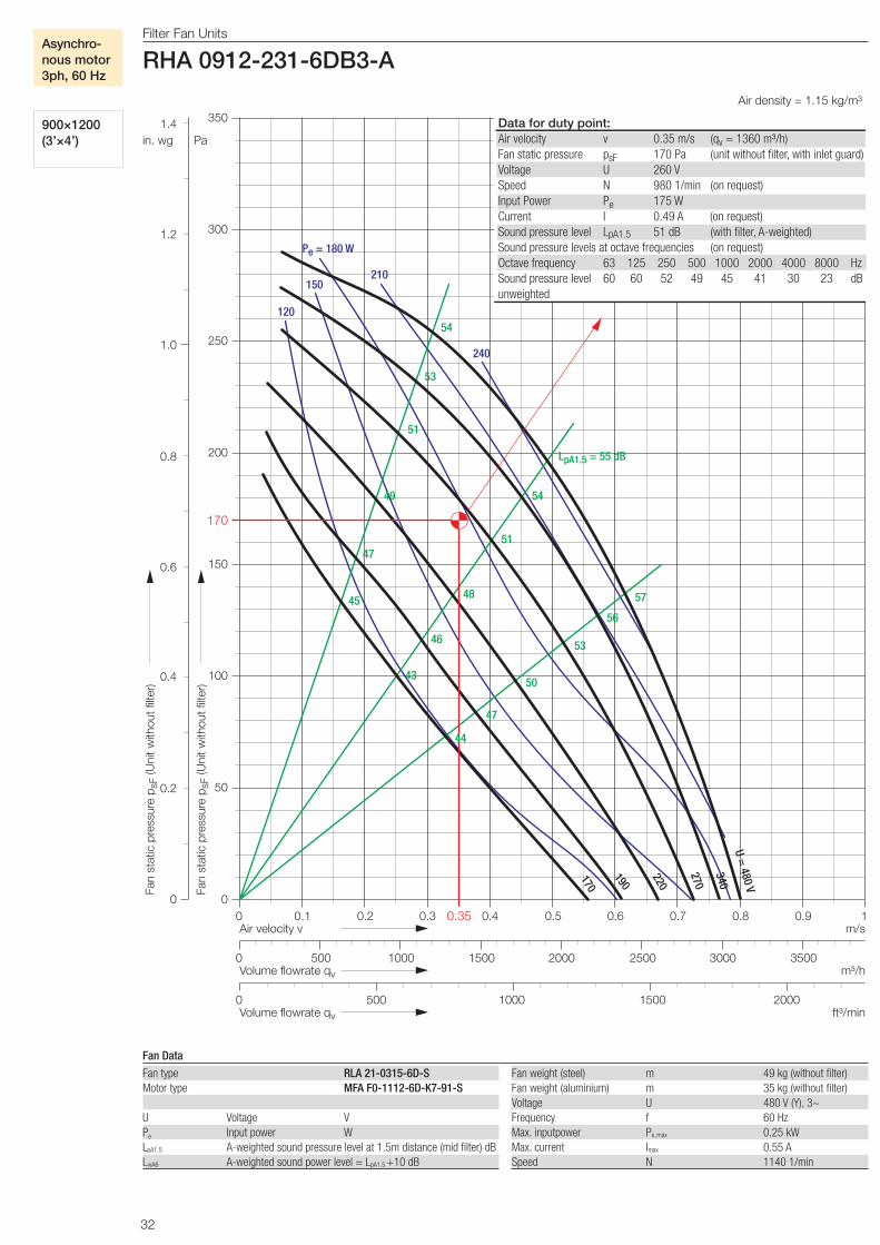
Filter Fan Units RHA 0912-231-6DB3-A
Air density = 1.15 kg/m³
0
50
100
150
200
250
0 0.1 0.2 0.3 0.4 0.5 0.6 0.7 0.8 0.9 1 Air velocity v
Pa
Fan
stat
ic p
ress
ure
p sF
(Uni
t with
out f
ilter
)
m/s
0 1000 2000 3000 Volume flowrate qv m³/h
0 1000 1500 2000 Volume flowrate qv ft³/min
500
500 1500 2500 3500
300
350
0
0.2
0.4
0.6
0.8
1.0
in. wg Fa
n st
atic
pre
ssur
e p s
F (U
nit w
ithou
t filt
er)
1.2
1.4
Data for duty point: Air velocity v 0.35 m/s (qv = 1360 m³/h) Fan static pressure psF 170 Pa (unit without filter, with inlet guard) Voltage U 260 V Speed N 980 1/min (on request) Input Power Pe 175 W Current I 0.49 A (on request) Sound pressure level LpA1.5 51 dB (with filter, A-weighted) Sound pressure levels at octave frequencies (on request) Octave frequency 63 125 250 500 1000 2000 4000 8000 Hz Sound pressure level 60 60 52 49 45 41 30 23 dB unweighted
170
0.35
240
Pe = 180 W
210 150
120 54
53
51
49
47
LpA1.5 = 55 dB
54
51
46
43
56
53
50
47
44
57 48 45
U = 480 V
270
340
190
170
220
Filter Fan Units
RHA 0912-231-6DB3-A
900×1200 (3’×4’)
Asynchro-nous motor3ph, 60 Hz
Fan Data
Fan weight (steel) m 49 kg (without filter)Fan weight (aluminium) m 35 kg (without filter)Voltage U 480 V (Y), 3~Frequency f 60 HzMax. inputpower Pe,max 0.25 kWMax. current Imax 0.55 ASpeed N 1140 1/min
Fan type RLA 21-0315-6D-SMotor type MFA F0-1112-6D-K7-91-S
U Voltage VPe Input power WLpA1.5 A-weighted sound pressure level at 1.5m distance (mid filter) dBLwA6 A-weighted sound power level = LpA1.5
+10 dB
33
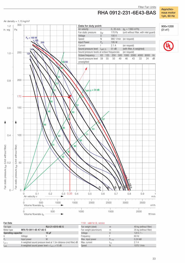
Filter Fan Units
RHA 0912-231-6E43-BASAir density = 1.15 kg/m³
0
50
100
150
200
250
0 0.1 0.2 0.3 0.4 0.5 0.6 0.7 0.8 0.9 1Air velocity v
Pa
Fan
stat
ic p
ress
ure
p sF
(Uni
t with
out f
ilter
)
m/s
300
0
0.2
0.4
0.6
0.8
1.0
in. wg
Fan
stat
ic p
ress
ure
p sF
(Uni
t with
out f
ilter
)
1.2
0 1000 2000 3000Volume flowrate qv m³/h
0 1000 1500 2000Volume flowrate qv ft³/min
500
500 1500 2500 3500
Data for duty point:Air velocity v 0,.35 m/s (qv = 1360 m³/h) Fan static pressure psF 170 Pa (unit without filter, with inlet guard)Voltage U 100 V Speed N 980 1/min (on request) Input Power Pe 195 W Current I 2.1 A (on request) Sound pressure level LpA1.5 51 dB (with filter, A-weighted) Sound pressure levels at octave frequencies (on request) Octave frequency 63 125 250 500 1000 2000 4000 8000 HzSound pressure level 59 55 50 49 46 43 33 24 dBunweighted 230
180200
Pe = 160 W
140
120
54
54
53
52
50
48
LpA1.5 = 54 dB
53
51
50
46
41
57
56
53
51
46
40
49
51
43
48
43
49
U = 120 V
10090858075
95
110115
170
0.35
®
Filter Fan Units
RHA 0912-231-6E43-BAS
900×1200 (3’×4’)
Asynchro-nous motor1ph, 60 Hz
Fan type RLA 21-0315-6E-SMotor type MFA F0-0911-6E-K7-A0-SOperating capacitor 16 µFU Voltage VPe
Input power WLpA1,5
A-weighted sound pressure level at 1.5m distance (mid filter) dBLwA6
A-weighted sound power level = LpA1.5 +10 dB
Fan Data 115V - valid for UL-version
Fan weight (steel) m 49 kg (without filter)Fan weight (aluminium) m 35 kg (without filter)Voltage U 120 V, 1~Frequency f 60 HzMax. input power Pe, max 0.24 kWMax. current Imax 2.1 ASpeed N 1070 1/min

34
Filter Fan Units RHA 0612-331-4DB4-A
Air density = 1.15 kg/m³
0
50
100
150
200
250
0 0.1 0.2 0.3 0.4 0.5 0.6 0.7 0.8 0.9 1 Air velocity v
Pa
Fan
stat
ic p
ress
ure
p sF
(Uni
t with
out f
ilter
)
m/s
m³/h
Volume flowrate qv ft³/min
300
350
450
1.1 1.2
0 1000 2000 3000
0 1000 1500 500
Volume flowrate qv
500 1500 2500
0
in. wg Fa
n st
atic
pre
ssur
e p s
F (U
nit w
ithou
t filt
er)
0.2
0.4
0.6
0.8
1.0
1.2
1.4
1.6
1.8
400
Data for duty point: Air velocity v 0.35 m/s (qv = 910 m³/h) Fan static pressure psF 170 Pa (unit without filter, with inlet guard) Voltage U 240 V Speed N 1240 1/min (on request) Input Power Pe 189 W Current I 0.56 A (on request) Sound pressure level LpA1.5 50 dB (with filter, A-weighted) Sound pressure levels at octave frequencies (on request) Octave frequency 63 125 250 500 1000 2000 4000 8000 Hz Sound pressure level 60 63 51 44 41 38 32 25 dB unweighted
Pe = 240 W
210
180 150
120
270
300
57
56
53
51
48
55
51
48
58
58
56
48
LpA1.5= 57 dB
57
58
45
45
52
U = 480 V
360
300
260
230
205
180
170
0.35
Filter Fan Units
RHA 0612-331-4DB4-A
600×1200 (2’×4’)
Asynchro-nous motor3ph, 60 Hz
Fan Data
Fan weight (steel) m 43 kg (without filter)Fan weight (aluminium) m 32 kg (without filter)Voltage U 480 V (Y), 3~Frequency f 60 HzMax. inputpower Pe,max 0.31 kWMax. current Imax 0.60 ASpeed N 1660 1/min
Fan type RLA 31-2831-4D-SMotor type MFA F0-0911-4D-K7-90-S
U Voltage VPe Input power WLpA1.5 A-weighted sound pressure level at 1.5m distance (mid filter) dBLwA6 A-weighted sound power level = LpA1.5
+10 dB
35
®
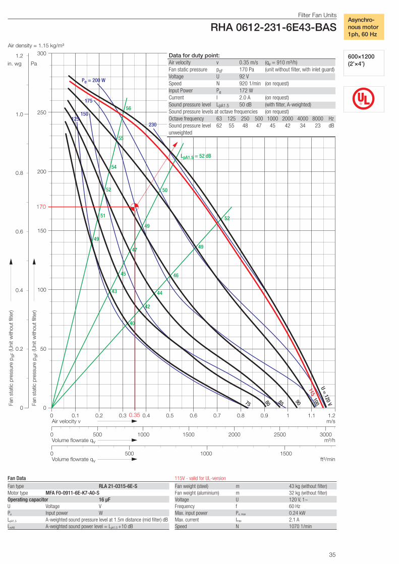
Filter Fan Units
RHA 0612-231-6E43-BASAir density = 1.15 kg/m³
0
50
100
150
200
250
Pa
Fan
stat
ic p
ress
ure
p sF
(Uni
t with
out f
ilter
)
300
0
0.2
0.4
0.6
0.8
1.0
in. wg
Fan
stat
ic p
ress
ure
p sF
(Uni
t with
out f
ilter
)
1.2
0 0.1 0.2 0.3 0.4 0.5 0.6 0.7 0.8 0.9 1Air velocity v m/s
m³/h
Volume flowrate qv ft³/min
1.1 1.2
0 1000 2000 3000
0 1000 1500500
Volume flowrate qv
500 1500 2500
Data for duty point:Air velocity v 0.35 m/s (qv = 910 m³/h) Fan static pressure psF 170 Pa (unit without filter, with inlet guard)Voltage U 92 V Speed N 920 1/min (on request) Input Power Pe 172 W Current I 2.0 A (on request) Sound pressure level LpA1.5 50 dB (with filter, A-weighted) Sound pressure levels at octave frequencies (on request) Octave frequency 63 125 250 500 1000 2000 4000 8000 HzSound pressure level 62 55 48 47 45 42 34 23 dBunweighted
230
175
150
Pe = 200 W
125
56
55
54
52
51
49
LpA1.5 = 52 dB
50
49
47
45
43
52
49
46
44
42
40
115
U = 120 V75
908580
100
170
0.35
Filter Fan Units
RHA 0612-231-6E43-BAS
600×1200 (2’×4’)
Asynchro-nous motor1ph, 60 Hz
Fan type RLA 21-0315-6E-SMotor type MFA F0-0911-6E-K7-A0-SOperating capacitor 16 µFU Voltage VPe
Input power WLpA1,5
A-weighted sound pressure level at 1.5m distance (mid filter) dBLwA6
A-weighted sound power level = LpA1.5 +10 dB
Fan Data 115V - valid for UL-version
Fan weight (steel) m 43 kg (without filter)Fan weight (aluminium) m 32 kg (without filter)Voltage U 120 V, 1~Frequency f 60 HzMax. input power Pe, max 0.24 kWMax. current Imax 2.1 ASpeed N 1070 1/min

36
EN
- S
P3.
6-FF
U –
0 0
00-1
0.20
08
Nicotra Gebhardt S.p.A
Via Modena, 18 24040 Zingonia (Bergamo) Italy
Phone +39 (0)35 873 111 Fax +39 (0)35 884 319 E-Mail [email protected]
www.nicotra-gebhardt.com
Nicotra Gebhardt GmbH
Gebhardtstrasse 19-25 74638 Waldenburg Germany
Phone +49 (0)7942 101 0 Fax +49 (0)7942 101 170 E-Mail [email protected]
www.nicotra-gebhardt.com
SPAIN Ctra. Alcalá-Villar del Olmo, Km. 2,83028810 Villalbilla-Madrid Phone +34 918-846110Fax +34 918-859450E-mail [email protected]
c/.Coso, 67-75, esc. 1.a,1.oB50001 Zaragoza Phone +34 976-290550Fax +34 976-298127E-mail [email protected]
BELGIUM Haeghensgoed, 13 - 00/019270 LaarnePhone +32 (0)9-336-00-01Fax +32 (0)9-336-00-05E-mail [email protected]
FRANCE Leader‘s Park Bat A13 chemin des Cytises69340 FranchevillePhone +33 (0)4 72 79 01 20Fax +33 (0)4 72 79 01 21E-mail [email protected]
SWEDEN Box 237Kraketorpsgatan 3043123 Mölndal Phone 0046 31-874540Fax 0046 31-878590E-mail [email protected]://www.nicotra-gebhardt.se/
GREAT BRITAIN Unit D, Rail Mill WayParkgate Business ParkRotherhamSouth YorkshireS62 6JQPhone +044 01709-780760Fax +044 01709-780762 E-mail [email protected]
Monarch House1-7 Smyth RoadBedminsterBristol Phone +44 (0)870 043-5207Fax +44 (0)870 043-5212E-mail [email protected]://www.kiloheat.co.uk/
MALAYSIA Lot 1799, Jalan BalakongTaman Perindustrian Bukit Belimbing 43300 Seri Kembangan SelangorPhone +603 8961-2588 Fax +603 8961-8337 E-mail [email protected]
THAILAND 6/29 Soi Suksawadi 2, Moo 4, Suksawadi Road, Kwang Jomthong, Khet Jomthong, Bangkok 10150Phone +662 476-1823-6Fax +662 476-1827E-mail [email protected]
SINGAPORE No. 15 West Coast Highway# 04-08 Pasir Panjang BuildingSingapore 117861 Phone (065) 6265-1522Fax (065) 6265-2400E-mail [email protected]
AUSTRALIA47 Jesica Road,Campbellfield, VIC 3061Phone +613 9357-7464Fax +613 9357-8700E-mail [email protected]
INDIAPlot no 28f, Sector-31Kasna, Greater Noida-201308U.P. INDIAPhone +91 0120-4203400Fax +91 0120-4203401E-mail [email protected]
CHINA88 Tai‘An Road, XinQiao, ShiJi, Panyu Guangzhou 511450PR CHINA Phone +86 (0)20-39960570Fax +86 (0)20-39960569 E-mail [email protected]
UNITED STATESPO BOX 900921Sandy, Utah 84090Phone 001(801) 733-0248 Fax 001(801) 315-9400 Mobile 001(801) 682 0898E-mail [email protected]://www.gebhardtfans.com/
Nicotra Gebhardt worldwide
Top Related