


Languages
Pages
Legal


Fan Coil Units
0.79 to 8.75kW
0.49 to 4.90kWModels SVC, SVN, SHC, SHN
94 to 9303/h
SysCoil 2


SysCoil 2 1
Quality, efficiency and reliabilityVertical console units with cabinet, SVC typeSVC vertical console units are designed for use in three different types of installation:
Q as a wall hung console in areas where a skirting board prevents the use of a floor mounted console ;
Q as a floor console with optional front air intake FA (most frequently located below a large window) ;
Q as a floor console with support feet and bottom air intake.They feature a modern decorative style cabinet with matching plastic discharge grille, providing a high performance unit that is attractive and durable which will complement any room decor.The SVC models can be fitted, as optional, with electromechanical or electronic Aqu@Net control, with valve kits, etc.
Vertical concealed units without cabinet, SVN typeSVN vertical chassis only units are designed for applications that require a fully concealed or a fully recessed installation.These units include all the features of the SVC vertical console unit type except that only the chassis is supplied instead of decorative style cabinet.Like the SVC units, Aqu@Net control (except the remote control) as well as other electromechanical controls and valve kits can be fitted, as optional, on unit.Units can be fitted with optional feet (supplied loose), if floor mounting is required.
Ceiling exposed units with cabinet, SHC typeSHC ceiling exposed units are designed for ceiling mounting in areas where it is necessary to conserve floor space. They contain all the features of the SVC unit within the decorative style cabinet with matching plastic discharge grille. Standard version is designed for rear horizontal air intake without inlet grille.Similar to the previous models, the Aqu@Net control can be supplied, as optional, on SHC units with remote control. Other optional controls and valve kits are also available.
Ceiling concealed units without cabinet, SHN typeSHN ceiling chassis units are designed for concealed or recessed ceiling installations. This unit consists of the SHC basic unit horizontally installed. SHN units contain all the features of the SHC ceiling exposed units except that only the chassis casing is supplied instead of the decorative style cabinet.Possibility of supplying separately an optional Aqu@Net type remote control for wall mounting. Other optional controls and valve kits are also available.
Support feet supplied as optional
Bottom air intake grille supplied as optional
SysCoil 22
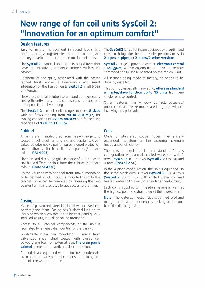
New range of fan coil units SysCoil 2: "Innovation for an optimum comfort"
Easy to install, improvement in sound levels and performances, Aqu@Net electronic control, etc., are the key developments carried on our fan coil units.
The SysCoil 2 II fan coil unit range is issued from that development striving to meet customers’ wishes and advices.
Aesthetic of the grille, associated with the casing refined finish allows a harmonious and smart integration of the fan coil units SysCoil 2 in all types of interiors.
They are the ideal solution to air condition agreeably and efficiently, flats, hotels, hospitals, offices and other premises, all year long.
The SysCoil 2 fan coil units range includes 8 sizes with air flows ranging from 94 to 930 m3/h, for cooling capacities of 490 to 4870 W and for heating capacities of 1270 to 11590 W.
The SysCoil 2 fan coil units are equipped with optimized coils to bring the best possible performances in 2-pipes, 4-pipes, or 2-pipes/2-wires versions.
SysCoil 2 range is provided with an electronic control : Aqu@Net, whose ergonomic and discrete remote command can be loose or fitted on the fan coil unit.
All settings being made at factory, no needs to be done by installer.
This control, especially innovating, offers as standard a master/slave function up to 15 units from one single remote control.
Other features like window contact, occupied/unoccupied, antifreeze modes are integrated without involving any price add.
Design features
CabinetAll units are manufactured from heavy-gauge zinc coated sheet steel for long life and durability. Oven baked powder epoxy paint insures a good protection and an attractive finish for all outside panels (Standard colour : RAL 9003).
The standard discharge grille is made of "ABS" plastic and has a different colour from the cabinet (standard colour : Pantone 427C).
On the versions with optional front intake, monobloc grille, painted in RAL 9003, is mounted flush to the cabinet. Grille can be removed by releasing the two quarter turn fixing screws to get access to the filter.
CasingMade of galvanized steel insulated with closed cell polyethylene foam. Casing has 3 slotted lugs on its rear side which allow the unit to be easily and quickly installed at site, in wall or ceiling mounting.
Access to all internal components of the unit is facilitated by an easy dismounting of the casing.
Condensate drain pan monoblock is made from galvanized sheet steel coated with closed cell polyethylene foam on external face. The drain pan is painted to ensure the anticorrosion protection.
All models are equipped with an inclined condensate drain pan to ensure optimal condensate draining and to minimize water retention.
Coils Made of staggered copper tubes, mechanically expanded into aluminium fins, assuring maximum heat transfer efficiency.
The units are equipped, in their standard 2-pipes configuration, with a main chilled water coil with 2 rows (SysCoil 2 10), 3 rows (SysCoil 2 20 to 70) and 4 rows (SysCoil 2 90).
In the 4-pipes configuration, the unit is equipped , in the same block with 3 rows (SysCoil 2 10), 4 rows (SysCoil 2 20 to 90), with chilled water coil and heated water coil 1 row (on an independent circuit).
Each coil is supplied with headers having air vent at the highest point and drain plug at the lowest point.
Note : The water connection side is defined left-hand or right-hand when observer is looking at the unit from the discharge side.

SysCoil 2 3
Fan and motor assemblyThe units are fitted with a fan-motor assembly of which the fan is composed of double inlet forward curved centrifugal wheel(s) dynamically balanced and specially designed for an optimal air flow and a low noise level..
The SysCoil 2 range can be supplied with 2 types of motor :
Q The standard AC motor of asynchrone direct drive type having 5 speeds, 3 of them are factory pre-wired, equipped with a built-in normally closed thermal protection of automatic reset type.
Q The EC motor of high efficiency and low electrical consumption type for a significant energy saving. The motor is suitable for 0-10 V input, ensuring variable speed capability. It is fitted with ECospeed3 interface card (supplied as standard) for a 3-speed optimized running.
Power supply :
230 V±10%/1 Ph/50 Hz - 60 Hz.
Electrical connectionsUnits are supplied complete with internal electrical wiring terminating in a junction block protected by a cap or the cabinet.
Cabinet internal space allows installation of optional control systems supplied by manufacturer or others.
When the optional Aqu@Net control is fitted on the unit, the controller includes a junction block for power supply connection and incorporates, as standard, a cable clamp.
FilterFilter media is mounted on a metallic frame.
Efficiency: G2 / G3
OptionsMany different options and accessories are available for all units : see chapter "Mounting accessories".
New range of fan coil units SysCoil 2: "Innovation for an optimum comfort"
ControlsSysCoil 2 units can be factory fitted with the following optional controls :
Electronic communicating Aqu@Net control with RCL remote control
Aqu@Net controller can be provided with NIU interface card to be used with µBMS or eNIU interface card for connection to a BMS via ModBus protocol.
Electromechanical or electronic control for wall mounting.
Electromechanical control : CMV, TBMV.
TRM-FA
TAE20
RCL remote control
µBMS and NIU interface card
TBMV
CMV

SysCoil 24
Models designationSC10 . VC . SYS . 2P . 500W . EC . S1S3S4 . L . G3 . CMV . 3W . FTG + FA
REP. Description
Size SC10 : SysCoil 2 10 SC20 : SysCoil 2 20
SC30 : SysCoil 2 30 SC40 : SysCoil 2 40
SC50 : SysCoil 2 50 SC60 : SysCoil 2 60
SC70 : SysCoil 2 70 SC90 : SysCoil 2 90
Version
VC : Console mouting Model with casing VN : Console mouting Model without casing
HC : Horizontal ceiling mounting Model with casing HN : Horizontal ceiling mounting Model without casing
Brand SYS : SYSTEMAIR
Coil 2P : 2 pipes 4P : 4 pipes
Electric heater
Blank : Without heater 500W : Capacity 500W 1000W : Capacity 1000W
1250W : Capacity 1250W 2500W : Capacity 2500W
Fan type Blank : AC fan EC : EC fan
Wired speed
Blank : Standard wired (S1S3S5) S1 : Speed 1 S2 : Speed 2
S3 : Speed 3 S4 : Speed 4 S5 : Speed 5
Service side L : Left R : Right
Air filter G2 : G2 filter G3 : G3 filter
Regulation
Blank : Terminal block CMV : Manual switch TBMV : Manual thermostat + Manual Change over + Fan speed selector D : Aquanet 2 pipes/without valve/ cooling only E : Aquanet 2 pipes/valve/cooling only F : Aquanet 2 pipes/without valve/ heating only G : Aquanet 2 pipes/valve/heating only H : Aquanet 2 pipes/valve/heating only/ Change over
J : Aquanet 2 pipes/without valve/ heating only/Change over L : Aquanet 4 pipes/valve M : Aquanet 2 pipes/cooling only/ electric heater N : Aquanet 2 pipes/without valve/ reversible cycle /Change over P : Aquanet 2 pipes/valve/ reversible cycles/Change over Q : Aquanet 2 pipes/valve/ reversible cycle/Change over/ electric heater
ValveBlank : Without valve 2W : 2 way valve 3W : 3 way valve
Air intake
Blank : Without feet FT : feet FTG : feet + grid BACK-MO : Back air intake/ auto damper
BACK-MA : Back air intake/manual damper FLOOR-MO : Floor air intake/auto damper FLOOR-MA : Floor air intake/ manual damper
Option
FA-REMOV : Front air intake/ removable panel FA : Front air intake FH : Fuse holder PUMP : Condensate lift pump C/O : Change over
RCL : Remote control RCL NIU : µBMS compatible communication board NIU for Aquanet eNIU : Modbus communication board eNIU for Aquanet NOECO : Without Ecospeed3

SysCoil 2 5
AC Motor
Product Codes
EC Motor
2 pipes 4 pipesSVN SHN SVN SHN
20Product codes
ORACLE 7OG034001 7OG034005 7OG034003 7OG034007
M3 369060 369064 369062 369066
description .SC20.VN.2P.L.G2.+ .SC20.HN.2P.L.G2.+ .SC20.VN.4P.L.G2.+ .SC20.HN.4P.L.G2.+
30Product codes
ORACLE 7OG034011 7OG034015 7OG034013 7OG034017
M3 369068 369072 369070 369074
description .SC30.VN.2P.L.G2.+ .SC30.HN.2P.L.G2.+ .SC30.VN.4P.L.G2.+ .SC30.HN.4P.L.G2.+
40Product codes
ORACLE 7OG034021 7OG034025 7OG034023 7OG034027
M3 369076 369080 369078 369082
description .SC40.VN.2P.L.G2.+ .SC40.HN.2P.L.G2.+ .SC40.VN.4P.L.G2.+ .SC40.HN.4P.L.+
50Product codes
ORACLE 7OG034031 7OG034035 7OG034033 7OG034037
M3 369084 369088 369086 369090
description .SC50.VN.2P.L.G2.+ .SC50.HN.2P.L.G2.+ .SC50.VN.4P.L.G2.+ .SC50.HN.4P.L.G2.+
60Product codes
ORACLE 7OG034041 7OG034045 7OG034043 7OG034047
M3 369092 369096 369094 369098
description .SC60.VN.2P.L.G2.+ .SC60.HN.2P.L.G2.+ .SC60.VN.4P.L.G2.+ .SC60.HN.4P.L.G2.+
2 pipes 4 pipesSVN SHN SVN SHN
20Product codes
ORACLE 7OG034002 7OG034006 7OG034004 7OG034008
M3 369061 369065 369063 369067
description .SC20.VN.2P.EC.L.G2.+ .SC20.HN.2P.EC.L.G2.+ .SC20.VN.4P.EC.L.G2.+ .SC20.HN.4P.EC.L.G2.+
30Product codes
ORACLE 7OG034012 7OG034016 7OG034014 7OG034018
M3 369069 369073 369071 369075
description .SC30.VN.2P.EC.L.G2.+ .SC30.HN.2P.EC.L.G2.+ .SC30.VN.4P.EC.L.G2.+ .SC30.HN.4P.EC.L.G2.+
40Product codes
ORACLE 7OG034022 7OG034026 7OG034024 7OG034028
M3 369077 369081 369079 369083
description .SC40.VN.2P.EC.L.G2.+ .SC40.HN.2P.EC.L.G2.+ .SC40.VN.4P.EC.L.G2.+ .SC40.HN.4P.EC.L.G2.+
50Product codes
ORACLE 7OG034032 7OG034036 7OG034034 7OG034038
M3 369085 369089 369087 369091
description .SC50.VN.2P.EC.L.G2.+ .SC50.HN.2P.EC.L.+ .SC50.VN.4P.EC.L.G2.+ .SC50.HN.4P.EC.L.G2.+
60Product codes
ORACLE 7OG034042 7OG034046 7OG034044 7OG034048
M3 369093 369097 369095 369099
description .SC60.VN.2P.EC.L.G2.+ .SC60.HN.2P.EC.L.G2.+ .SC60.VN.4P.EC.L.G2.+ .SC60.HN.4P.EC.L.G2.+

SysCoil 26
Energy performance of SysCoil 2 with new generation EC motor
3-speed control interface for EC motorAqu@Net Interface card EC motor
3 speeds 0 to 10 V
ECoSpeed3
Electrical consumption with EC motor (in Watts) Energy savings
Models Size 10 Size 20 Size 30 Size 40 Size 50 Size 60 Size 70 Size 90V1 8 8 6 3 3 3 N.C N.C
V2 9 9 15 8 12 17 N.C N.C
V3 14 15 19 13 24 29 N.C N.C
V4 21 23 23 30 32 37 N.C N.C
V5 41 42 45 43 46 53 N.C N.C
Without control consumption, static pressure 0 Pa.
Electrical consumption with AC motor (in Watts)
Models Size 10 Size 20 Size 30 Size 40 Size 50 Size 60 Size 70 Size 90V1 14 14 24 18 24 39 N.C N.C
V2 21 20 43 32 45 64 N.C N.C
V3 24 23 50 39 55 76 N.C N.C
V4 29 28 62 45 65 90 N.C N.C
V5 36 35 81 59 86 112 N.C N.C
Without control consumption, static pressure 0 Pa.
Models Size 10 Size 20 Size 30 Size 40 Size 50 Size 60 Size 70 Size 90V1 14 14 24 18 24 39 N.C N.C
V2 20 20 43 32 45 63 N.C N.C
V3 24 23 50 39 54 75 N.C N.C
V4 29 28 62 45 64 90 N.C N.C
V5 36 34 81 58 86 110 N.C N.C
Without control consumption, static pressure 0 Pa.
2-pipes System
4-pipes System
2-pipes System
4-pipes System
Models Size 10 Size 20 Size 30 Size 40 Size 50 Size 60 Size 70 Size 90V1 8 8 6 3 3 3 N.C N.C
V2 9 9 14 8 11 16 N.C N.C
V3 14 15 18 12 23 28 N.C N.C
V4 20 23 22 28 30 36 N.C N.C
V5 39 40 43 42 44 51 N.C N.C
Without control consumption, static pressure 0 Pa.

STD FT / FTG FA
FLOOR-MO */ FLOOR-MA * BACK-MO */ BACK-MA *
SysCoil 2 7
SysCoil 2 - Mounting AccessoriesWall mounting with cabinet - SysCoil 2 SVC
STD standard version for wall mounting (no support feet supplied).FT support feet for floor mounting.FTG air intake grille between feet.FA front air intake grille (no support feet supplied).BACK-MO air intake arrangement with motorized (non controlled) on/off damper (back or front intake).FLOOR-MO air intake arrangement with motorized (non controlled) on/off damper (floor or front intake).BACK-MA air intake arrangement with manual damper (back or/and front intake).FLOOR-MA air intake arrangement with manual damper (floor or/and front intake).
* Can be fitted with optional intake grille between feet

STD FT FA
FLOOR-MO / FLOOR-MA BACK-MO / BACK-MA
SysCoil 28
SysCoil 2 - Mounting AccessoriesWall mounting without cabinet - SysCoil 2 SVN
STD standard version for wall mounting (no support feet supplied).FT support feet for floor mounting.FA front air intake.
BACK-MO air intake arrangement with motorized (non controlled) on/off damper (back or front intake).
FLOOR-MO air intake arrangement with motorized (non controlled) on/off damper (floor or front intake).BACK-MA air intake arrangement with manual damper (back or/and front intake).FLOOR-MA air intake arrangement with manual damper (floor or/and front intake).

STD FT / FTG
FLOOR-MO */ FLOOR-MA * FA
SysCoil 2 9
SysCoil 2 - Mounting AccessoriesCeiling mounting with cabinet - SysCoil 2 SHCSTD standard ceiling mounted version with rear air intake (no inlet grille).FA bottom air intake grille.FLOOR-MO air intake arrangement with motorized (non controlled) on/off damper.FLOOR-MA air intake arrangement with manual damper.FT support feet.FTG air intake grille between feet.
* Can be fitted with optional intake grille between feet

STD
FLOOR-MO / FLOOR-MA FA
SysCoil 210
SysCoil 2 - Mounting Accessories
STD standard ceiling mounted version with rear air intake (no inlet grille).FLOOR-MO air intake arrangement with motorized (non controlled) on/off damper.FLOOR-MA air intake arrangement with manual damper.FA bottom air intake.
Ceiling mounting without cabinet - SysCoil 2 SHN

SysCoil 2 11
2-way control valve - 2-pipes system - 230 Volt thermal actuator
W2G11 valve, 2-way type - For 2-pipes system on cooling or heating coil
Valve Thermal actuator 230 V - 50/60 Hz
Models KV Ø T max amb
T max fluid Id (A) In (A) P (VA)
10/60 1,6 1/2" 50 °C 110 °C 0,6 0,013 3,0
70/90 2,5 3/4" 50 °C 110 °C 0,6 0,013 3,0
2-way control valve - 4-pipes system - 230 Volt thermal actuator
3-way control valve - 2-pipes system - 230 Volt thermal actuator
3-way control valve - 4-pipes system - 230 Volt thermal actuator
W2G22 valves. 2-way type - For 4-pipes system on cooling and heating coilsCooling valve
Heating valve
Moteur(s) thermique(s) 230 V - 50/60 Hz
Models KV Ø KV Ø T max amb
T max fluid Id (A) In (A) P (VA)
10/60 1,6 1/2" 1,6 1/2" 50 °C 110 °C 0,6 0,013 3,0
70/90 2,5 3/4" 1,6 1/2" 50 °C 110 °C 0,6 0,013 3,0
W4G11 valve. 3-way type - For 2-pipes system on cooling or heating coil
Valve Thermal actuator 230 V - 50/60 Hz
Models KV Ø T max amb
T max fluid Id (A) In (A) P (VA)
10/60 1,6 1/2" 50 °C 110 °C 0,6 0,013 3,0
70/90 2,5 3/4" 50 °C 110 °C 0,6 0,013 3,0
W4G22 valves. 3-way type - For 4-pipes system on cooling and heating coilsCooling valve
Heating valve
Thermal actuator(s) 230 V - 50/60 Hz
Models KV Ø KV Ø T max amb
T max fluid Id (A) In (A) P (VA)
10/60 1,6 1/2" 1,6 1/2" 50 °C 110 °C 0,6 0,013 3,0
70/90 2,5 3/4" 1,6 1/2" 50 °C 110 °C 0,6 0,013 3,0
Available Options
SysCoil 212
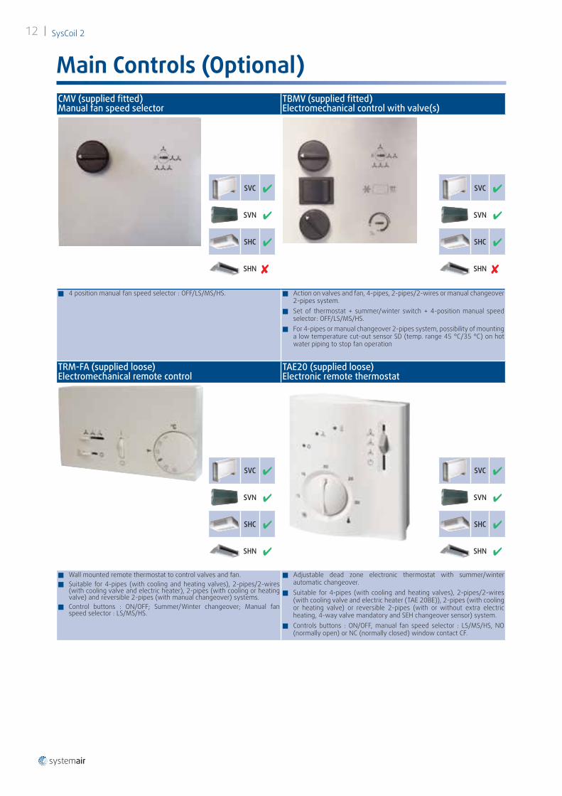
Main Controls (Optional)CMV (supplied fitted) Manual fan speed selector
TBMV (supplied fitted) Electromechanical control with valve(s)
Q 4 position manual fan speed selector : OFF/LS/MS/HS. Q Action on valves and fan, 4-pipes, 2-pipes/2-wires or manual changeover 2-pipes system.
Q Set of thermostat + summer/winter switch + 4-position manual speed selector: OFF/LS/MS/HS.
Q For 4-pipes or manual changeover 2-pipes system, possibility of mounting a low temperature cut-out sensor SD (temp. range 45 °C/35 °C) on hot water piping to stop fan operation
TRM-FA (supplied loose) Electromechanical remote control
TAE20 (supplied loose) Electronic remote thermostat
Q Wall mounted remote thermostat to control valves and fan. Q Suitable for 4-pipes (with cooling and heating valves), 2-pipes/2-wires
(with cooling valve and electric heater), 2-pipes (with cooling or heating valve) and reversible 2-pipes (with manual changeover) systems.
Q Control buttons : ON/OFF; Summer/Winter changeover; Manual fan speed selector : LS/MS/HS.
Q Adjustable dead zone electronic thermostat with summer/winter automatic changeover.
Q Suitable for 4-pipes (with cooling and heating valves), 2-pipes/2-wires (with cooling valve and electric heater (TAE 20BE)), 2-pipes (with cooling or heating valve) or reversible 2-pipes (with or without extra electric heating, 4-way valve mandatory and SEH changeover sensor) system.
Q Controls buttons : ON/OFF, manual fan speed selector : LS/MS/HS, NO (normally open) or NC (normally closed) window contact CF.
SVC ✔
SVN ✔
SHC ✔
SHN ✘
SVC ✔
SVN ✔
SHC ✔
SHN ✘
SVC ✔
SVN ✔
SHC ✔
SHN ✔
SVC ✔
SVN ✔
SHC ✔
SHN ✔

SysCoil 2 13
Main Controls (Optional)Aqu@Net communicating electronic control FCC electronic controller (supplied fitted)
Aqu@Net communicating electronic control System networking
up to100 units
FCCcontroller
RCLwire remote control
Bus RS485
µBMSMinisupervisionstation
up to100 units
MODE NIGHT
TEMP
HOUR
SET
CLEAR
+PROG
SWING
UNITDAY
LOCAL
Wed
AUTO
UNIT
°C
Q Controller can be configured in 2-pipes heating only or cooling only, 2-pipes/2-wires, reversible 2-pipes with or without extra electric heating or 4-pipe system.
Q Other pre-programmed functionalities included : master/slaves up to 15 units controlled from one remote control only; NC window contact; automatic or manual selection of unoccupied mode; antifreeze mode.
Q RS485 communication bus system allowing user to monitor 100 fan coil units through a supervision station (µBMS), with FCC Aqu@Net controllers fitted with interface boards (NIU) and with local controls (RCL). Max. length of bus = 1000 meters, shielded twisted pair cable.
RCL wire remote control with digital display (supplied loose or fitted)
µBMS programmable supervision station (supplied loose)
Q Wire remote control for wall mounting or for mounting on AWC units. Q Keyboard with locking device and buttons : ON/Standby; fan operation
(auto or manual); operation mode (cooling, heating, auto or fan operation only); temperature setpoint adjustment in different modes.
Q Functioning LED.
Q In association with FCC controllers through a communication bus and interface board (NIU), µBMS allows 15 different zones with 100 units to be managed.
Q Other functionalities included either in global or individual control by zone : O Daily and weekly programming of running times (2 hour ranges), O Programming and setting of temperature setpoints (cooling, heating,
auto), O Choice of operation mode (cooling, heating, auto or fan operation
only), O Choice of fan operation speed (auto or manual).
SVC ✔
SVN ✔
SHC ✔
SHN ✔
NIU board

SysCoil 214
Technical Data
Water volume (liters)
Operating limits
Environmental conditionsMinimum premise air temperature / new air intake / around the apparatus 5 °C / 15% HR
Maximale premise air temperature / new air intake / around the apparatus 32 °C / 70% HR
Water circuitMax. operating pressure 5 bars
Min. entering water temperature (without glycol) +5 °C
Max. entering water temperature +90 °C
Models
Water volume (liters)2 pipes 4 pipes
10 0.41 0.41 0.20
20 0.61 0.61 0.20
30 0.89 0.89 0.30
40 1.17 1.17 0.39
50 1.45 1.45 0.48
60 1.73 1.73 0.58
70 2.19 2.19 0.73
90 2.19 2.6 0.92
(1) Available in 2 steps suitable for Aqu@Net control.
Electrical data
Models
without electric heating
with electric heatingBE1 BE2
Max. absorbed current
heating capacity Max. absorbed current
heating capacity Max. absorbed current
AC motor EC motor AC motor EC motor AC motor EC motorA A W A A W A A
10 0.15 0.27 500 2.32 2.44/ / /
20 0.15 0.31 500 2.32 2.48/ / /
30 0.38 0.29 500 2.55 2.46 1000 (1)
(500+500) 4.73 4.64
40 0.26 0.36 1250 5.69 5.79 2500 (1)
(1250+1250) 11.13 11.23
50 0.39 0.34 1250 5.82 5.77 2500 (1)
(1250+1250) 11.26 11.21
60 0.48 0.46 1250 5.91 5.89 2500 (1)
(1250+1250) 11.35 11.33
70 0.70 0.60 1250 6.13 6.03 2500 (1)
(1250+1250) 11.57 11.47
90 0.72 1.88 1250 6.15 7.31 2500 (1)
(1250+1250) 11.59 12.75
Operating range with EC motor : Voltage setpoint
ModelsMinimum starting voltage (V)
Maximum voltage (V)
10 2 10
20 2 10
30 2 10
40 2 10
50 2 10
60 2 10
70 2 N.C
80 2 N.C
SysCoil 2 15
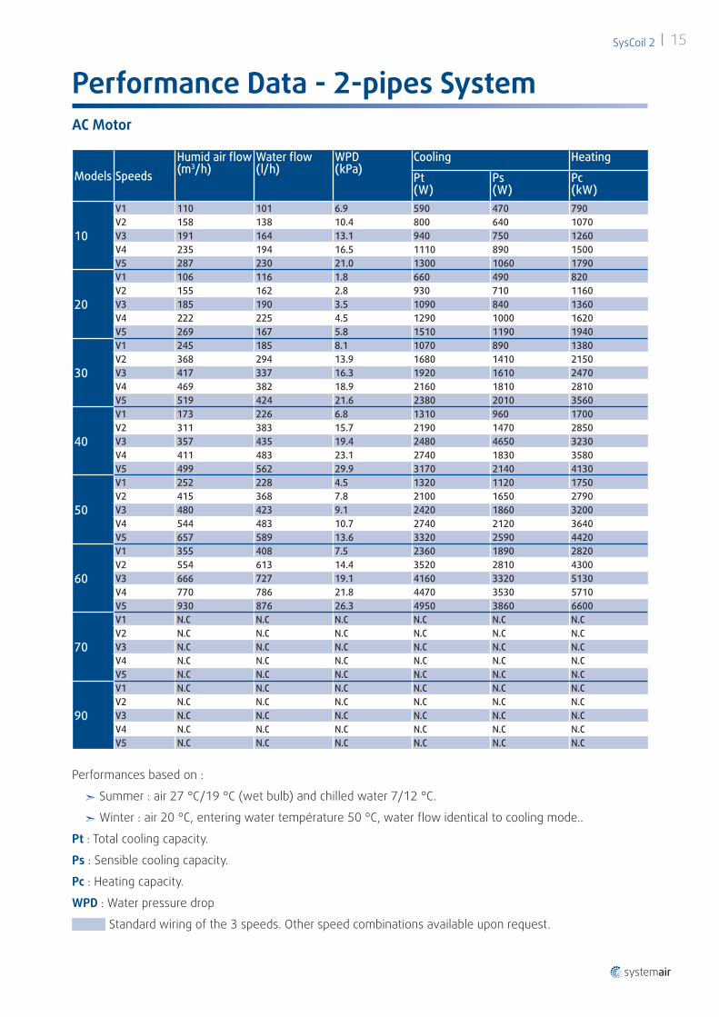
Performance Data - 2-pipes System
Models SpeedsHumid air flow (m3/h)
Water flow (l/h)
WPD (kPa)
Cooling Heating
Pt (W)
Ps (W)
Pc (kW)
10
V1 110 101 6.9 590 470 790V2 158 138 10.4 800 640 1070V3 191 164 13.1 940 750 1260V4 235 194 16.5 1110 890 1500V5 287 230 21.0 1300 1060 1790
20
V1 106 116 1.8 660 490 820V2 155 162 2.8 930 710 1160V3 185 190 3.5 1090 840 1360V4 222 225 4.5 1290 1000 1620V5 269 167 5.8 1510 1190 1940
30
V1 245 185 8.1 1070 890 1380V2 368 294 13.9 1680 1410 2150V3 417 337 16.3 1920 1610 2470V4 469 382 18.9 2160 1810 2810V5 519 424 21.6 2380 2010 3560
40
V1 173 226 6.8 1310 960 1700V2 311 383 15.7 2190 1470 2850V3 357 435 19.4 2480 4650 3230V4 411 483 23.1 2740 1830 3580V5 499 562 29.9 3170 2140 4130
50
V1 252 228 4.5 1320 1120 1750V2 415 368 7.8 2100 1650 2790V3 480 423 9.1 2420 1860 3200V4 544 483 10.7 2740 2120 3640V5 657 589 13.6 3320 2590 4420
60
V1 355 408 7.5 2360 1890 2820V2 554 613 14.4 3520 2810 4300V3 666 727 19.1 4160 3320 5130V4 770 786 21.8 4470 3530 5710V5 930 876 26.3 4950 3860 6600
70
V1 N.C N.C N.C N.C N.C N.CV2 N.C N.C N.C N.C N.C N.CV3 N.C N.C N.C N.C N.C N.CV4 N.C N.C N.C N.C N.C N.CV5 N.C N.C N.C N.C N.C N.C
90
V1 N.C N.C N.C N.C N.C N.CV2 N.C N.C N.C N.C N.C N.CV3 N.C N.C N.C N.C N.C N.CV4 N.C N.C N.C N.C N.C N.CV5 N.C N.C N.C N.C N.C N.C
Performances based on :
² Summer : air 27 °C/19 °C (wet bulb) and chilled water 7/12 °C.
² Winter : air 20 °C, entering water température 50 °C, water flow identical to cooling mode..
Pt : Total cooling capacity.
Ps : Sensible cooling capacity.
Pc : Heating capacity.
WPD : Water pressure drop
Standard wiring of the 3 speeds. Other speed combinations available upon request.
AC Motor

SysCoil 216
Performance Data - 2-pipes System
Performances based on :
² Summer : air 27 °C/19 °C (wet bulb) and chilled water 7/12 °C.
² Winter : air 20 °C, entering water température 50 °C, water flow identical to cooling mode..
Pt : Total cooling capacity.
Ps : Sensible cooling capacity.
Pc : Heating capacity.
WPD : Water pressure drop
Standard wiring of the 3 speeds. Other speed combinations available upon request.
EC Motor
Models SpeedsHumid air flow (m3/h)
Water flow (l/h)
WPD (kPa)
Cooling Heating
Pt (W)
Ps (W)
Pc (kW)
10
V1 121 109 7.7 640 510 860V2 165 144 10.9 830 660 1110V3 243 200 17.2 1140 920 1550V4 315 250 23.7 1410 1160 1950V5 423 325 35.0 1820 1510 2550
20
V1 112 121 2.0 700 520 860V2 188 193 4.0 1110 850 1380V3 239 240 5.0 1370 1070 1740V4 313 306 7.0 1710 1370 2240V5 416 398 11.0 2200 1780 2950
30
V1 164 113 5.0 670 560 870V2 330 260 12.0 1500 1250 1920V3 369 295 14.0 1690 1410 2160V4 399 322 15.0 1840 1540 2350V5 530 434 22.0 2430 2050 3790
40
V1 170 222 7.0 1290 950 1670V2 322 396 17.0 2260 1520 2940V3 412 484 23.0 2750 1840 3580V4 588 641 38.0 3600 2440 4690V5 678 722 46.0 4040 2750 5260
50
V1 229 209 4.1 1210 1040 1600V2 663 456 10.0 2600 2000 3440V3 663 594 13.7 3360 2610 4460V4 735 662 15.7 3720 2910 4960V5 818 739 18.1 4150 3250 5530
60
V1 266 346 5.1 1850 1480 2160V2 592 653 15.9 3740 2990 4580V3 733 765 20.8 4360 3460 5500V4 801 803 22.7 4560 3590 5880V5 903 861 25.5 4870 3800 6450
70
V1 N.C N.C N.C N.C N.C N.CV2 N.C N.C N.C N.C N.C N.CV3 N.C N.C N.C N.C N.C N.CV4 N.C N.C N.C N.C N.C N.CV5 N.C N.C N.C N.C N.C N.C
90
V1 N.C N.C N.C N.C N.C N.CV2 N.C N.C N.C N.C N.C N.CV3 N.C N.C N.C N.C N.C N.CV4 N.C N.C N.C N.C N.C N.CV5 N.C N.C N.C N.C N.C N.C

SysCoil 2 17
Performance Data - 4-pipes System
Models SpeedsHumid air flow (m3/h)
Cooling HeatingPt (kW)
Ps (kW)
Water flow (l/h)
WPD (kPa)
Pc (kW)
Water flow (l/h)
WPD (kPa)
10
V1 94 490 390 84 5.3 1270 102 1.3V2 138 670 530 116 8.0 1620 136 2.2V3 168 800 630 138 10.0 1870 159 2.9V4 206 940 760 165 12.8 2150 185 3.8V5 252 1110 900 195 16.3 2450 211 4.9
20
V1 89 560 390 95 1.2 1340 117 1.1V2 134 790 580 135 2.0 1620 140 1.5V3 163 930 700 161 2.6 1790 155 1.8V4 199 1110 850 193 3.4 2010 174 2.1V5 240 1310 1020 229 4.5 2360 203 2.7
30
V1 228 940 790 162 7.5 2470 211 7.1V2 347 1500 1260 263 12.3 3220 272 9.2V3 391 1710 1440 300 14.1 3500 295 9.9V4 437 1920 1610 338 16.0 3790 317 10.7V5 475 2080 1740 369 17.5 4020 335 11.3
40
V1 162 1180 880 203 5.5 2580 212 4.8V2 290 1960 1330 342 12.9 3940 332 9.3V3 335 2240 1490 391 16.2 4420 374 11.2V4 384 2490 1660 438 19.7 4880 415 13.2V5 467 2870 1940 509 25.2 5590 476 16.4
50
V1 239 1180 1000 203 3.1 3090 266 12.5V2 395 1880 1470 326 5.7 4480 383 19.2V3 454 2140 1650 373 6.8 5010 427 21.9V4 512 2410 1850 421 8.0 5450 466 24.4V5 614 2890 2240 511 10.4 6140 525 28.3
60
V1 329 2100 1680 361 5.7 4470 382 15.8V2 523 3160 2520 550 11.8 6140 525 25.8V3 626 3730 2970 651 15.8 7020 601 32.1V4 729 4110 3260 722 19.0 7780 663 37.7V5 873 4520 3540 800 22.9 8750 740 45.2
70
V1 N.C N.C N.C N.C N.C N.C N.C N.CV2 N.C N.C N.C N.C N.C N.C N.C N.CV3 N.C N.C N.C N.C N.C N.C N.C N.CV4 N.C N.C N.C N.C N.C N.C N.C N.CV5 N.C N.C N.C N.C N.C N.C N.C N.C
90
V1 N.C N.C N.C N.C N.C N.C N.C N.CV2 N.C N.C N.C N.C N.C N.C N.C N.CV3 N.C N.C N.C N.C N.C N.C N.C N.CV4 N.C N.C N.C N.C N.C N.C N.C N.CV5 N.C N.C N.C N.C N.C N.C N.C N.C
Performances based on :
² Summer : air 27 °C/19 °C (wet bulb) and chilled water 7/12 °C.
² Winter : air 20 °C, hot water 70/60 °C
Pt : Total cooling capacity.
Ps : Sensible cooling capacity.
Pc : Heating capacity.
WPD : Water pressure drop
Standard wiring of the 3 speeds. Other speed combinations available upon request
AC Motor

SysCoil 218
Performance Data - 4-pipes System
Models SpeedsHumid air flow (m3/h)
Cooling HeatingPt (kW)
Ps (kW)
Water flow (l/h)
WPD (kPa)
Pc (kW)
Water flow (l/h)
WPD (kPa)
10
V1 96 500 390 86 5.4 1290 103 1.4V2 135 660 520 114 7.8 1600 133 2.1V3 206 940 760 165 12.8 2150 185 3.8V4 272 1180 960 208 17.9 2590 222 5.3V5 378 1560 1280 277 27.6 3290 281 8.3
20
V1 89 560 390 95 1.2 1340 117 1.1V2 158 910 680 156 2.5 1760 153 1.7V3 203 1130 870 197 3.5 2030 176 2.2V4 276 1470 1170 261 5.6 2780 238 3.6V5 377 1920 1580 349 9.2 3960 334 6.4
30
V1 140 530 440 88 4.0 1910 165 5.6V2 292 1250 1040 216 10.1 2870 244 8.2V3 331 1430 1200 249 11.6 3120 264 8.9V4 361 1570 1320 275 12.9 3310 279 9.4V5 489 2140 1790 380 18.0 4110 341 11.5
40
V1 148 1100 830 187 4.9 2430 199 4.4V2 285 1930 1310 337 12.6 3890 327 9.1V3 369 2430 1610 425 18.7 4750 404 12.6V4 540 3210 2180 571 31.3 6210 530 19.5V5 627 3610 2480 645 38.9 6950 594 23.6
50
V1 200 1000 880 172 2.6 2740 236 11.0V2 457 2150 1660 375 6.8 5040 430 22.1V3 594 2800 2170 493 9.9 6000 514 27.5V4 667 3150 2450 557 11.7 6490 556 30.4V5 758 3580 2800 637 14.2 7100 609 34.2
60
V1 215 1480 1180 250 3.2 3490 298 10.9V2 524 3170 2530 551 11.8 6150 526 25.9V3 667 3940 3140 589 17.5 7370 630 34.6V4 737 4140 3280 726 19.2 7830 667 38.0V5 842 4430 3480 783 22.0 8540 723 43.4
70
V1 N.C N.C N.C N.C N.C N.C N.C N.CV2 N.C N.C N.C N.C N.C N.C N.C N.CV3 N.C N.C N.C N.C N.C N.C N.C N.CV4 N.C N.C N.C N.C N.C N.C N.C N.CV5 N.C N.C N.C N.C N.C N.C N.C N.C
90
V1 N.C N.C N.C N.C N.C N.C N.C N.CV2 N.C N.C N.C N.C N.C N.C N.C N.CV3 N.C N.C N.C N.C N.C N.C N.C N.CV4 N.C N.C N.C N.C N.C N.C N.C N.CV5 N.C N.C N.C N.C N.C N.C N.C N.C
Performances based on :
² Summer : air 27 °C/19 °C (wet bulb) and chilled water 7/12 °C.
² Winter : air 20 °C, hot water 70/60 °C
Pt : Total cooling capacity.
Ps : Sensible cooling capacity.
Pc : Heating capacity.
WPD : Water pressure drop
Standard wiring of the 3 speeds. Other speed combinations available upon request
EC Motor

SysCoil 2 19
Sound Data
Models SpeedsSysCoil 2 - 2 pipes SysCoil 2 - 4 pipesLw global (dBA)
Lp* global (dBA)
NR* Lw global (dBA)
Lp* global (dBA)
NR*
10
V1 33 19 10 31 18 10V2 38 22 13 36 21 12V3 41 24 15 39 23 14V4 44 27 18 42 25 16V5 47 31 22 45 29 19
20
V1 32 17 7 28 14 4V2 40 25 15 37 22 12V3 44 29 19 41 26 16V4 48 34 23 46 31 21V5 51 39 27 49 36 25
30
V1 42 27 17 40 25 15V2 53 37 27 51 35 25V3 56 41 32 55 38 30V4 59 46 37 58 43 34V5 62 50 43 60 46 38
40
V1 29 14 5 28 12 4V2 43 27 18 41 25 16V3 46 30 21 44 29 20V4 49 33 24 47 32 23V5 52 37 27 51 36 26
50
V1 37 19 12 36 18 11V2 46 29 20 45 27 19V3 49 32 22 48 30 21V4 51 34 25 50 33 23V5 54 38 28 53 36 27
60
V1 40 24 14 39 23 13V2 48 32 24 47 31 23V3 52 36 28 51 35 27V4 55 39 31 54 38 30V5 58 42 34 57 41 33
70
V1 N.C N.C N.C N.C N.C N.CV2 N.C N.C N.C N.C N.C N.CV3 N.C N.C N.C N.C N.C N.CV4 N.C N.C N.C N.C N.C N.CV5 N.C N.C N.C N.C N.C N.C
90
V1 N.C N.C N.C N.C N.C N.CV2 N.C N.C N.C N.C N.C N.CV3 N.C N.C N.C N.C N.C N.CV4 N.C N.C N.C N.C N.C N.CV5 N.C N.C N.C N.C N.C N.C
(*) Informative data, considering a sound attenuation of the room and installation of 16 dB.
AC Motor

SysCoil 220
Sound Data
Models SpeedsSysCoil 2 - 2 pipes SysCoil 2 - 4 pipesLw global (dBA)
Lp* global (dBA)
NR* Lw global (dBA)
Lp* global (dBA)
NR*
10
V1 41 25 16 39 24 15V2 44 28 19 42 26 17V3 50 33 25 47 31 22V4 55 38 29 52 35 26V5 61 45 35 59 42 33
20
V1 37 21 11 34 18 7V2 45 30 21 42 26 17V3 50 34 26 47 31 22V4 56 40 31 53 38 29V5 62 46 35 60 44 34
30
V1 33 23 12 30 22 9V2 50 34 26 47 32 23V3 53 37 26 50 34 26V4 55 39 31 53 36 28V5 62 48 38 60 45 36
40
V1 30 15 5 29 13 3V2 41 25 16 39 23 14V3 46 31 22 44 28 19V4 54 39 29 52 37 28V5 57 42 32 55 40 31
50
V1 34 19 5 33 17 3V2 47 31 22 44 28 19V3 52 36 28 50 34 25V4 55 39 31 52 36 28V5 58 42 33 56 40 31
60
V1 31 15 7 28 12 4V2 48 33 23 45 30 20V3 52 39 29 50 36 26V4 54 41 31 52 39 29V5 55 43 34 54 42 32
70
V1 N.C N.C N.C N.C N.C N.CV2 N.C N.C N.C N.C N.C N.CV3 N.C N.C N.C N.C N.C N.CV4 N.C N.C N.C N.C N.C N.CV5 N.C N.C N.C N.C N.C N.C
90
V1 N.C N.C N.C N.C N.C N.CV2 N.C N.C N.C N.C N.C N.CV3 N.C N.C N.C N.C N.C N.CV4 N.C N.C N.C N.C N.C N.CV5 N.C N.C N.C N.C N.C N.C
(*) Informative data, considering a sound attenuation of the room and installation of 16 dB.
EC Motor

100
202
13346
168 -G
EF
DC
B
A
Ground levelReturn
Discharge
condensate drain pan
M8 fixing screws4 x 8mm
210
133condensate outlet
Ø ext. 16mmElectrical sideprotection cap
225
100
B
G
Ground levelReturn
Discharge
100
202
1336046
168 -
H
G
EF
DC
B
A
Ground levelReturn
Discharge
condensate drain pan
M8 fixing screws4 x 8mm
SysCoil 2 21
DimensionsSysCoil 2 SVC
Dimensions are in millimeters ; weight in kilograms.
Front view Rear view - SVC 10 to 60
Bottom View
Top view
Models A B C D E F G H Weight10 439 477 189 428 415 149 766 / 19
20 439 477 189 428 415 149 766 / 19
30 624 477 374 613 415 149 951 / 22.5
40 809 477 559 798 415 149 1136 / 29
50 994 477 744 983 415 149 1321 / 32
60 1179 477 929 1168 415 149 1506 / 37
70 994 577 744 983 524 149 1321 208 37
90 1179 577 929 1168 524 149 1506 208 47
Rear view - SVC 70 - 90

100
EF
DC
Ground levelReturn
Discharge
M8 fixing screws4 x 8mm
Electrical sideprotection cap
condensate drain pan
210
133
220
condensate outletØ ext. 16mm
100
202
B
13346
168-G
A
Ground levelReturn
Discharge
100
202
1336046
168 -
H
G
EF
DC
B
A
Ground levelReturn
Discharge
condensate drain pan
M8 fixing screws4 x 8mm
SysCoil 222
DimensionsSysCoil 2 SVN
Dimensions are in millimeters ; weight in kilograms.
Front view Rear view - SVN 10 to 60
Bottom View
Top view
Models A B C D E F G H Weight10 439 430 189 428 415 149 677 / 13
20 439 430 189 428 415 149 677 / 13
30 624 430 374 613 415 149 862 / 15.5
40 809 430 559 798 415 149 1047 / 22
50 994 430 744 983 415 149 1232 / 24
60 1179 430 929 1168 415 149 1417 / 28
70 994 430 744 983 524 149 1232 208 29
90 1179 430 929 1168 524 149 1417 208 38
Rear view - SVN 70 - 90

210
133condensate outletØ ext. 16mm
Electrical sideprotection cap
B
G
Return
Discharge
173161
46
C
EF
DA
105
283
Return
Dischargecondensate drain pan
M8 fixing screws4 x 8mm
225
149173
4760
C
EF
207
H
DA
Return
Dischargecondensate drain pan
M8 fixing screws4 x 8mm
SysCoil 2 23
DimensionsSysCoil 2 SHC
Dimensions are in millimeters ; weight in kilograms.
Front view Rear view
Bottom View
Top view - SHC 10 to 60 Top view - SHC 70 - 90
Models A B C D E F G H Weight10 439 477 189 428 415 149 766 / 19
20 439 477 189 428 415 149 766 / 19
30 624 477 374 613 415 149 951 / 22.5
40 809 477 559 798 415 149 1136 / 29
50 994 477 744 983 415 149 1321 / 32
60 1179 477 929 1168 415 149 1506 / 37
70 994 577 744 983 524 149 1321 208 37
90 1179 577 929 1168 524 149 1506 208 47

Electrical sideprotection capcondensate drain pan
105
283
173-
B
AG
Return
Discharge
161
46
C
EF
DA
Return
Discharge condensate drain pan
M8 fixing screws4 x 8mm
210
133
-
condensate outletØ ext. 16mm
173149
4760
C
EF
207
H
DA
Return
Dischargecondensate drain pan
M8 fixing screws4 x 8mm
SysCoil 224
DimensionsSysCoil 2 SHN
Dimensions are in millimeters ; weight in kilograms.
Front view Rear view
Bottom View
Top view - SHN 10 to 60 Top view - SHC 70 - 90
Models A B C D E F G H Weight10 439 430 189 428 415 149 677 / 13
20 439 430 189 428 415 149 677 / 13
30 624 430 374 613 415 149 862 / 15.5
40 809 430 559 798 415 149 1047 / 22
50 994 430 744 983 415 149 1232 / 24
60 1179 430 929 1168 415 149 1417 / 28
70 994 430 744 983 524 149 1232 208 29
90 1179 430 929 1168 524 149 1417 208 38

100 105
80
343
300
2
1
Ground level 10
0112
87
332
289
2
1
Ground level
100
143105
8068
408
343
300
278
4
3
2
1
Ground level 10
0
162112
87
375
332
289
245
4
3
2
1
Ground level
SysCoil 2 25
Dimensions - Water connectionsSysCoil 2 SVN / SVC 10
Inlet Outlet Inlet Outlet
2 pipes or or / /
4 pipes
Right - 4 pipes Left - 4 pipes
Right - 2 pipes Left - 2 pipes

100 105
80
343
300
2
1
Ground level 10
0112
8733
228
9
21
Ground level
100
168105
8068
408
343
300
278
4
3
21
Ground level 10
0
124112
9949
397
354
310
245
4
3
21
Ground level
SysCoil 226
Dimensions - Water connectionsSysCoil 2 SVN / SVC 20 to 60
Inlet Outlet Inlet Outlet
2 pipes or or / /
4 pipes
Right - 4 pipes Left - 4 pipes
Right - 2 pipes Left - 2 pipes
100 115
61
460
267
2
1
Ground level 10
0
138
43
445
268
2
1
Ground level
100
175115
10061
479
460
293
267
4
32
1
Ground level 10
0
176115
8140
468
454
291
269
4
3
2
1
Ground level
SysCoil 2 27
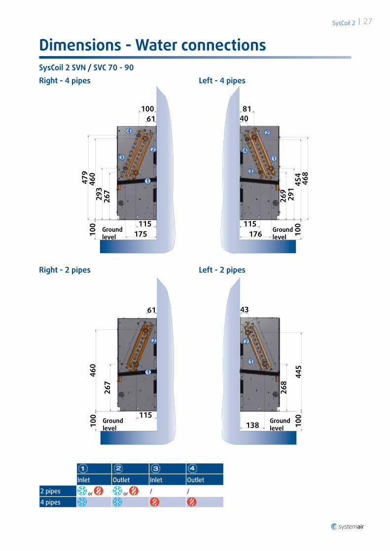
Dimensions - Water connectionsSysCoil 2 SVN / SVC 70 - 90
Inlet Outlet Inlet Outlet
2 pipes or or / /
4 pipes
Right - 4 pipes Left - 4 pipes
Right - 2 pipes Left - 2 pipes
325
141
91
2
1 ReturnDischarge
325
129
79
2
1Return Discharge
325346
204
141
91 544
32
1 ReturnDischarge
346325
204
141
9154
4
3
2
1Return Discharge
SysCoil 228
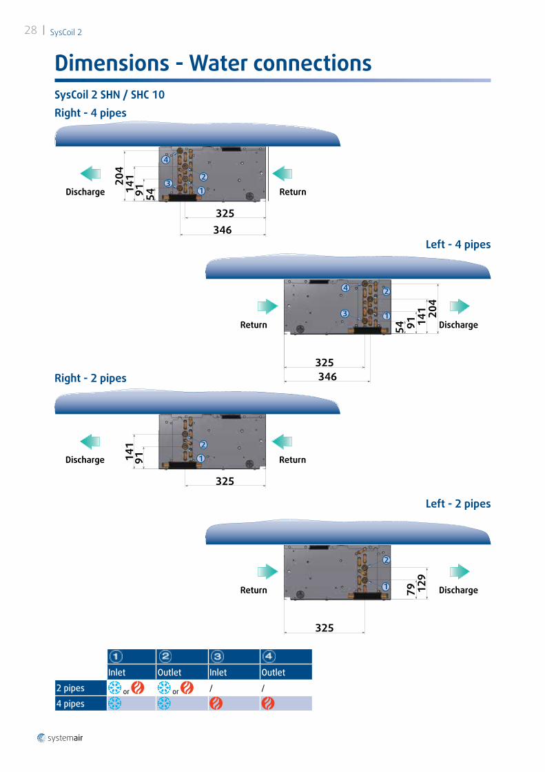
Dimensions - Water connectionsSysCoil 2 SHN / SHC 10
Inlet Outlet Inlet Outlet
2 pipes or or / /
4 pipes
Right - 4 pipes
Left - 4 pipes
Right - 2 pipes
Left - 2 pipes
325
141
92
21 ReturnDischarge
325
129
79
2
1Return Discharge
368
325346
204
141
91 414
32
1 ReturnDischarge
346
303325
204
141
9141
4
3
2
1Return Discharge
SysCoil 2 29
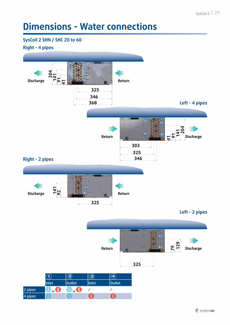
Dimensions - Water connectionsSysCoil 2 SHN / SHC 20 to 60
Inlet Outlet Inlet Outlet
2 pipes or or / /
4 pipes
Right - 4 pipes
Left - 4 pipes
Right - 2 pipes
Left - 2 pipes

460
267
159
104
21
ReturnDischarge
468
291
139
44
21Return Discharge
479460
267293
159
120
104
45
43
21
ReturnDischarge
468454
269291
180
139
105
44
43
21Return Discharge
SysCoil 230
Dimensions - Water connectionsSysCoil 2 SHN / SHC 70 - 90Right - 4 pipes
Left - 4 pipes
Inlet Outlet Inlet Outlet
2 pipes or or / /
4 pipes
Right - 2 pipes
Left - 2 pipes

SysCoil 2 31
Notes

SysCoil 232
Notes


june 2015
Syst
emai
r · E
DM S
YSCO
IL 2
-S-1
GB/0
6.15
- S
uper
sede
s : N
one
As p
art o
f our
ong
oing
pro
duct
impr
ovem
ent p
rogr
amm
e, o
ur p
rodu
cts
are
subj
ect t
o ch
ange
with
out p
rior n
otic
e. N
on c
ontr
actu
al p
hoto
s.
Systemair AC SAS · route de Verneuil, 27570 Tillières-sur- Avre · Tél. 02 32 60 61 00 · Fax 02 32 32 55 13www.systemair.fr
Top Related