


Languages
Pages
Legal

PR
OD
UC
TS
&
S
ER
VI
CE
S·
20
16
E X T E R N A L L I G H T N I N G P R O T E C T I O N

1EXTERNAL LIGHTNING PROTECTION
INGESCO® PDC ESE LIGHTNING RODS
DOWN CONDUCTORS
PASSIVE SYSTEMS
ACTIVE RODS
INGESCO® PDC.E ESE LIGHTNING RODS
LIGHTNING RODS
FASTENING AND CONNECTINGACCESSORIES
DOWN-CONDUCTOR PROTECTION
SPARK GAPS
CAPTURE SYSTEM ACCESSORIES
CONDUCTORS
12
10
08
06
16
20
32
40
41
23
31
a) If 2m≤ h ≤5m:
b) If ≥5m:
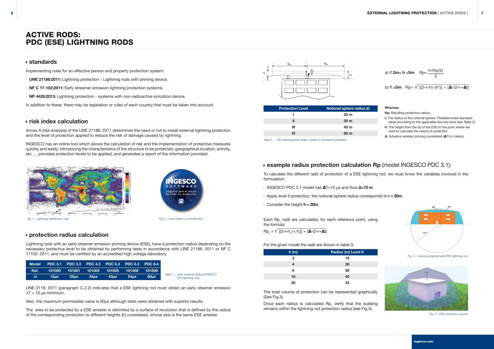
ACTIVE RODS: PDC (ESE) LIGHTNING RODS
Each Rpn radii are calculated, for each reference point, using the formula:
Rpn = √ [(2*r*hn )-( hn)] + [Δ*(2*r+Δ)]
For the given model the radii are shown in table 3:
The total volume of protection can be represented graphically (See Fig.3).
Once each radius is calculated Rp, verify that the building remains within the lightning rod protection radius (see Fig.4).
standardsImplementing rules for an effective person and property protection system:
· UNE 21186:2011: Lightning protection - Lightning rods with priming device.
· NF C 17-102:2011: Early streamer emission lightning protection systems.
· NP 4426:2013: Lightning protection - systems with non-radioactive ionization device.
In addition to these, there may be legislation or rules of each country that must be taken into account.
risk index calculationAnnex A (risk analysis) of the UNE 21186: 2011 determines the need or not to install external lightning protection and the level of protection applied to reduce the risk of damage caused by lightning.
INGESCO has an online tool which allows the calculation of risk and the implementation of protective measures quickly and easily. Introducing the characteristics of the structure to be protected, geographical location, activity, etc ..., provides protection levels to be applied, and generates a report of the information provided.
protection radius calculationLightning rods with an early steamer emission priming device (ESE), have a protection radius depending on the necessary protective level to be obtained by performing tests in accordance with UNE 21186: 2011 or NF C 17102: 2011, and must be certified by an accredited high voltage laboratory.
UNE 2118: 2011 (paragraph C.2.2) indicates that a ESE lightning rod must obtain an early steamer emission ∆T > 10 µs minimum.
Also, the maximum permissible value is 60µs although tests were obtained with superior results.
The area to be protected by a ESE arrester is delimited by a surface of revolution that is defined by the radius of the corresponding protection to different heights (h) considered, whose axis is the same ESE arrester.
Model PDC 3.1 PDC 3.3 PDC 4.3 PDC 5.3 PDC 6.3 PDC 6.4
Ref. 101000 101001 101003 101005 101008 101009
∆t 15µs 25µs 34µs 43µs 54µs 60µsTabla 1 – Early streamer ΔT(µs) INGESCO ESE lightning rods.
Fig. 1 – Lightning distribution map. Fig. 2 – www.ingesco.com/estudios
Fig. 4 – PDC protection volume.
Fig. 3 – Volume protected with PDC lightning rod.
Table 2 – The notional sphere radius r based on the level of protection.
Rp= √ [(2*r*h)-(h2)] + [Δ*(2*r+Δ)]
h*Rp(5)5
Rp=
Whereas:
Rp: Resulting protection radius.
r: The radius of the notional sphere. Predetermined standard value according to the applicable security level (see Table 2).
h: The height from the tip of the ESE to the point where we want to calculate the radius of protection.
Δ: Advance arrester priming considered (ΔT) in meters.
h (m)
2
4
6
10
20
Radius (m) Level II
15
30
38
40
43
Protection Level
I
II
III
IV
Notional sphere radius (r)
20 m
30 m
45 m
60 m
example radius protection calculation Rp (model INGESCO PDC 3.1):
To calculate the different radii of protection of a ESE lightning rod, we must know the variables involved in the formulation:
· INGESCO PDC 3.1 model has ΔT=15 µs and thus Δ=15 m.
· Apply level II protection, the notional sphere radius corresponds to r = 30m.
· Consider the height h = 20m.
EXTERNAL LIGHTNING PROTECTION | ACTIVE RODS |
2
ingesco.com
76
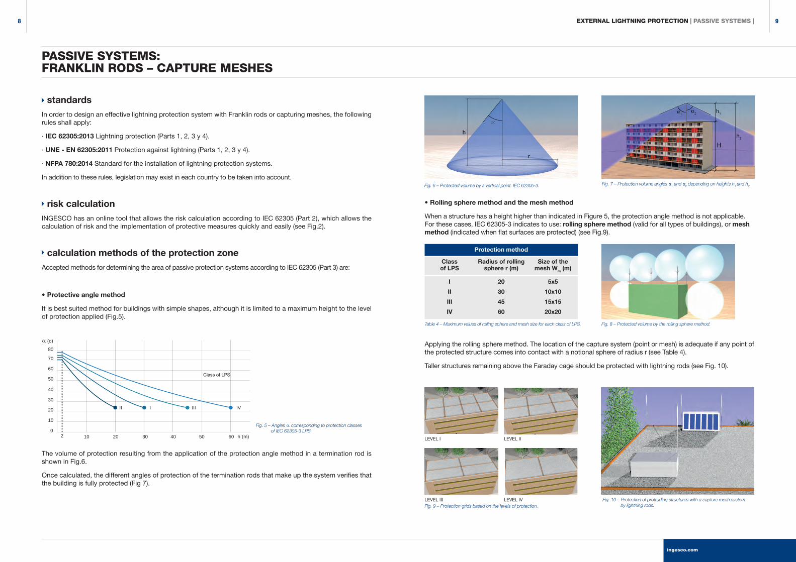
• Rolling sphere method and the mesh method
When a structure has a height higher than indicated in Figure 5, the protection angle method is not applicable. For these cases, IEC 62305-3 indicates to use: rolling sphere method (valid for all types of buildings), or mesh method (indicated when flat surfaces are protected) (see Fig.9).
Applying the rolling sphere method. The location of the capture system (point or mesh) is adequate if any point of the protected structure comes into contact with a notional sphere of radius r (see Table 4).
Taller structures remaining above the Faraday cage should be protected with lightning rods (see Fig. 10).
standardsIn order to design an effective lightning protection system with Franklin rods or capturing meshes, the following rules shall apply:
· IEC 62305:2013 Lightning protection (Parts 1, 2, 3 y 4).
· UNE - EN 62305:2011 Protection against lightning (Parts 1, 2, 3 y 4).
· NFPA 780:2014 Standard for the installation of lightning protection systems.
In addition to these rules, legislation may exist in each country to be taken into account.
risk calculationINGESCO has an online tool that allows the risk calculation according to IEC 62305 (Part 2), which allows the calculation of risk and the implementation of protective measures quickly and easily (see Fig.2).
calculation methods of the protection zoneAccepted methods for determining the area of passive protection systems according to IEC 62305 (Part 3) are:
• Protective angle method
It is best suited method for buildings with simple shapes, although it is limited to a maximum height to the level of protection applied (Fig.5).
The volume of protection resulting from the application of the protection angle method in a termination rod is shown in Fig.6.
Once calculated, the different angles of protection of the termination rods that make up the system verifies that the building is fully protected (Fig 7).
PASSIVE SYSTEMS:FRANKLIN RODS – CAPTURE MESHES
α
I
II
III
IV
20
30
45
60
5x5
10x10
15x15
20x20
Classof LPS
Radius of rolling sphere r (m)
Size of the mesh Wm (m)
Protection method
Fig. 7 – Protection volume angles α1 and α2 depending on heights h1 and h2.Fig. 6 – Protected volume by a vertical point. IEC 62305-3.
Table 4 – Maximum values of rolling sphere and mesh size for each class of LPS.
Fig. 10 – Protection of protruding structures with a capture mesh system by lightning rods.Fig. 9 – Protection grids based on the levels of protection.
LEVEL I
LEVEL III
LEVEL II
LEVEL IV
Fig. 8 – Protected volume by the rolling sphere method.
EXTERNAL LIGHTNING PROTECTION | PASSIVE SYSTEMS |
010 20 30 40 50 60
10
20
30
40
50
60
70
80α (o)
II I III IV
h (m)2
Class of LPS
Fig. 5 – Angles corresponding to protection classes of IEC 62305-3 LPS.
ingesco.com
98
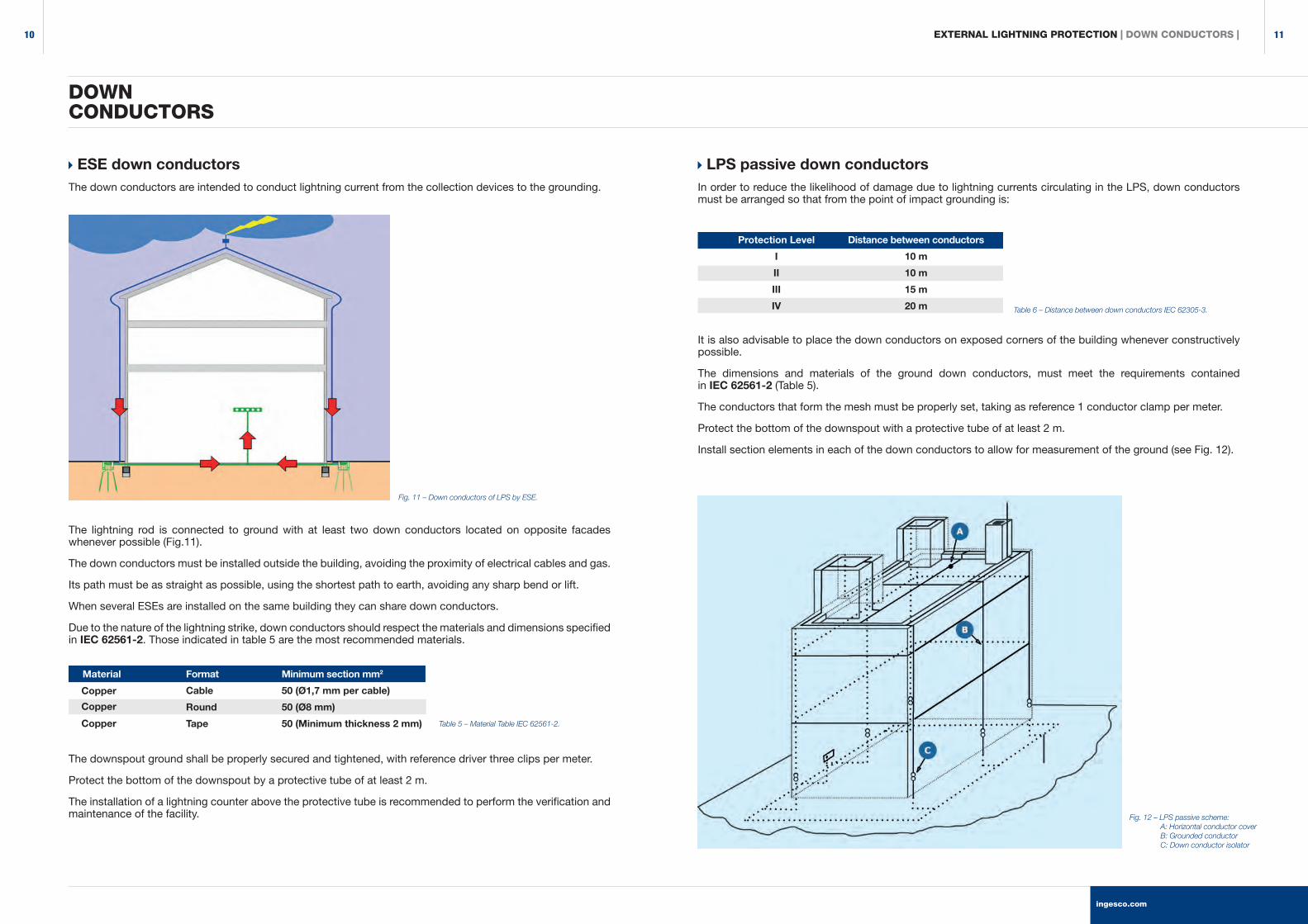
LPS passive down conductorsIn order to reduce the likelihood of damage due to lightning currents circulating in the LPS, down conductors must be arranged so that from the point of impact grounding is:
It is also advisable to place the down conductors on exposed corners of the building whenever constructively possible.
The dimensions and materials of the ground down conductors, must meet the requirements contained in IEC 62561-2 (Table 5).
The conductors that form the mesh must be properly set, taking as reference 1 conductor clamp per meter.
Protect the bottom of the downspout with a protective tube of at least 2 m.
Install section elements in each of the down conductors to allow for measurement of the ground (see Fig. 12).
ESE down conductorsThe down conductors are intended to conduct lightning current from the collection devices to the grounding.
The lightning rod is connected to ground with at least two down conductors located on opposite facades whenever possible (Fig.11).
The down conductors must be installed outside the building, avoiding the proximity of electrical cables and gas.
Its path must be as straight as possible, using the shortest path to earth, avoiding any sharp bend or lift.
When several ESEs are installed on the same building they can share down conductors.
Due to the nature of the lightning strike, down conductors should respect the materials and dimensions specified in IEC 62561-2. Those indicated in table 5 are the most recommended materials.
The downspout ground shall be properly secured and tightened, with reference driver three clips per meter.
Protect the bottom of the downspout by a protective tube of at least 2 m.
The installation of a lightning counter above the protective tube is recommended to perform the verification and maintenance of the facility.
DOWNCONDUCTORS
Fig. 12 – LPS passive scheme: A: Horizontal conductor cover B: Grounded conductor C: Down conductor isolator
Protection Level
I
II
III
IV
Distance between conductors
10 m
10 m
15 m
20 m
Minimum section mm2
50 (Ø1,7 mm per cable)
50 (Ø8 mm)
50 (Minimum thickness 2 mm)
Material Format
Cable
Round
Tape
Fig. 11 – Down conductors of LPS by ESE.
Table 5 – Material Table IEC 62561-2.
Table 6 – Distance between down conductors IEC 62305-3.
Copper
Copper
Copper
EXTERNAL LIGHTNING PROTECTION | DOWN CONDUCTORS |
ingesco.com
1110
EXTERNAL LIGHTNING PROTECTION | INGESCO® PDC LIGHTNING ROD |
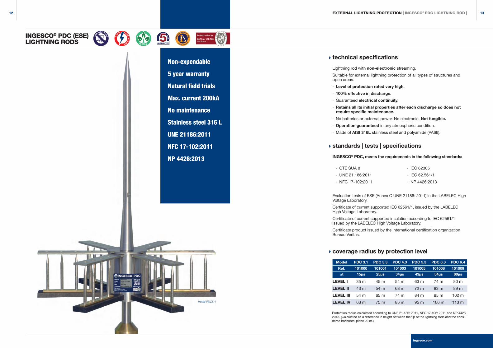
INGESCO® PDC (ESE)LIGHTNING RODS
Non-expendable
5 year warranty
Natural field trials
Max. current 200kA
No maintenance
Stainless steel 316 L
UNE 21186:2011
NFC 17-102:2011
NP 4426:2013
Model PDC6.4
technical specifications
Lightning rod with non-electronic streaming.
Suitable for external lightning protection of all types of structures and open areas.
· Level of protection rated very high.
· 100% effective in discharge.
· Guaranteed electrical continuity.
· Retains all its initial properties after each discharge so does not require specific maintenance.
· No batteries or external power. No electronic. Not fungible.
· Operation guaranteed in any atmospheric condition.
· Made of AISI 316L stainless steel and polyamide (PA66).
standards | tests | specifications
INGESCO® PDC, meets the requirements in the following standards:
· CTE SUA 8 · IEC 62305
· UNE 21.186:2011 · IEC 62.561/1
· NFC 17-102:2011 · NP 4426:2013
Evaluation tests of ESE (Annex C UNE 21186: 2011) in the LABELEC High Voltage Laboratory.
Certificate of current supported IEC 62561/1, issued by the LABELEC High Voltage Laboratory.
Certificate of current supported insulation according to IEC 62561/1 issued by the LABELEC High Voltage Laboratory.
Certificate product issued by the international certification organization Bureau Veritas.
coverage radius by protection level
Model PDC 3.1 PDC 3.3 PDC 4.3 PDC 5.3 PDC 6.3 PDC 6.4
Ref. 101000 101001 101003 101005 101008 101009
∆t 15µs 25µs 34µs 43µs 54µs 60µs
Protection radius calculated according to UNE 21.186: 2011, NFC 17.102: 2011 and NP 4426: 2013. (Calculated as a difference in height between the tip of the lightning rods and the consi-dered horizontal plane 20 m.).
LEVEL I
LEVEL II
LEVEL III
LEVEL IV
35 m
43 m
54 m
63 m
45 m
54 m
65 m
75 m
54 m
63 m
74 m
85 m
63 m
72 m
84 m
95 m
74 m
83 m
95 m
106 m
80 m
89 m
102 m
113 m
Product certified by
Certification
ingesco.com
1312
EXTERNAL LIGHTNING PROTECTION | INGESCO® PDC LIGHTNING ROD |
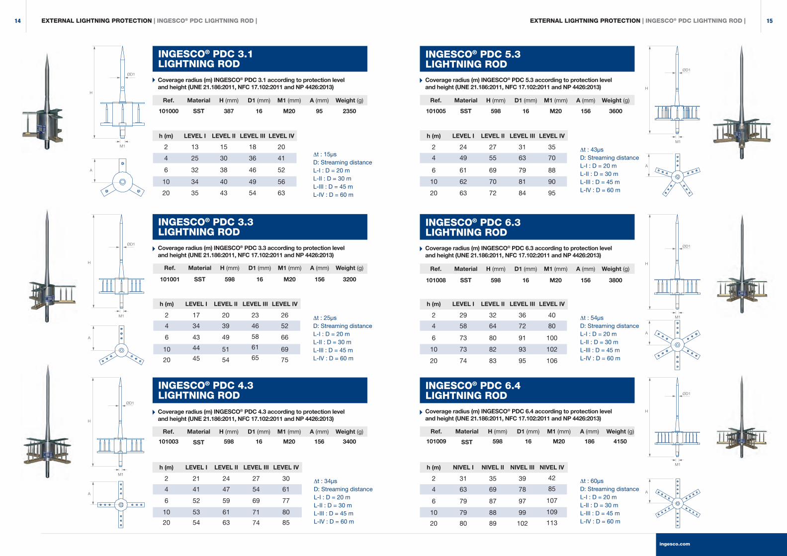
INGESCO® PDC 3.1LIGHTNING ROD
Coverage radius (m) INGESCO® PDC 3.1 according to protection level and height (UNE 21.186:2011, NFC 17.102:2011 and NP 4426:2013)
Coverage radius (m) INGESCO® PDC 3.3 according to protection level and height (UNE 21.186:2011, NFC 17.102:2011 and NP 4426:2013)
Coverage radius (m) INGESCO® PDC 4.3 according to protection level and height (UNE 21.186:2011, NFC 17.102:2011 and NP 4426:2013)
h (m)
2
4
6
10
20
LEVEL I
24
49
61
62
63
LEVEL II
27
55
69
70
72
LEVEL III
31
63
79
81
84
LEVEL IV
35
70
88
90
95
Ref.
101005
Material
SST
H (mm)
598
D1 (mm)
16
M1 (mm)
M20
A (mm)
156
Weight (g)
3600
h (m)
2
4
6
10
20
LEVEL I
17
34
43
44
45
LEVEL II
20
39
49
51
54
LEVEL III
23
46
58
61
65
LEVEL IV
26
52
66
69
75
Ref.
101001
Material
SST
H (mm)
598
D1 (mm)
16
M1 (mm)
M20
A (mm)
156
Weight (g)
3200
h (m)
2
4
6
10
20
LEVEL I
29
58
73
73
74
LEVEL II
32
64
80
82
83
LEVEL III
36
72
91
93
95
LEVEL IV
40
80
100
102
106
Ref.
101008
Material
SST
H (mm)
598
D1 (mm)
16
M1 (mm)
M20
A (mm)
156
Weight (g)
3800
h (m)
2
4
6
10
20
LEVEL I
21
41
52
53
54
LEVEL II
24
47
59
61
63
LEVEL III
27
54
69
71
74
LEVEL IV
30
61
77
80
85
Ref.
101003
Material
SST
H (mm)
598
D1 (mm)
16
M1 (mm)
M20
A (mm)
156
Weight (g)
3400
h (m)
2
4
6
10
20
NIVEL I
31
63
79
79
80
NIVEL II
35
69
87
88
89
NIVEL III
39
78
97
99
102
NIVEL IV
42
85
107
109
113
Ref.
101009
Material
SST
H (mm)
598
D1 (mm)
16
M1 (mm)
M20
A (mm)
186
Weight (g)
4150
h (m)
2
4
6
10
20
LEVEL I
13
25
32
34
35
LEVEL II
15
30
38
40
43
LEVEL III
18
36
46
49
54
LEVEL IV
20
41
52
56
63
Ref.
101000
Material
SST
H (mm)
387
D1 (mm)
16
M1 (mm)
M20
A (mm)
95
Weight (g)
2350
EXTERNAL LIGHTNING PROTECTION | INGESCO® PDC LIGHTNING ROD |
H
H
H
ØD1
ØD1
ØD1
M1
M1
M1
A
A
A
H
H
H
ØD1
M1
M1
M1
A
A
A
ØD1
ØD1
INGESCO® PDC 3.3LIGHTNING ROD
INGESCO® PDC 4.3LIGHTNING ROD
∆t : 25µsD: Streaming distanceL-I : D = 20 mL-II : D = 30 mL-III : D = 45 mL-IV : D = 60 m
∆t : 15µsD: Streaming distanceL-I : D = 20 mL-II : D = 30 mL-III : D = 45 mL-IV : D = 60 m
∆t : 34µsD: Streaming distanceL-I : D = 20 mL-II : D = 30 mL-III : D = 45 mL-IV : D = 60 m
INGESCO® PDC 5.3LIGHTNING ROD
INGESCO® PDC 6.3LIGHTNING ROD
INGESCO® PDC 6.4LIGHTNING ROD
Coverage radius (m) INGESCO® PDC 5.3 according to protection level and height (UNE 21.186:2011, NFC 17.102:2011 and NP 4426:2013)
Coverage radius (m) INGESCO® PDC 6.3 according to protection level and height (UNE 21.186:2011, NFC 17.102:2011 and NP 4426:2013)
Coverage radius (m) INGESCO® PDC 6.4 according to protection level and height (UNE 21.186:2011, NFC 17.102:2011 and NP 4426:2013)
∆t : 43µsD: Streaming distanceL-I : D = 20 mL-II : D = 30 mL-III : D = 45 mL-IV : D = 60 m
∆t : 54µsD: Streaming distanceL-I : D = 20 mL-II : D = 30 mL-III : D = 45 mL-IV : D = 60 m
∆t : 60µsD: Streaming distanceL-I : D = 20 mL-II : D = 30 mL-III : D = 45 mL-IV : D = 60 m
ingesco.com
1514

INGESCO® PDC.ELIGHTNING ROD
Model PDC.E 15 PDC.E 30 PDC.E 45 PDC.E 60
Ref. 102004 102005 102006 102007
∆t 15µs 30µs 45µs 60µs
LEVEL I
LEVEL II
LEVEL III
LEVEL IV
Model PDC.E 60
Protection radius calculated according to UNE 21.186: 2011, NFC 17.102: 2011 and NP 4426: 2013. (Calculated as a difference in height between the tip of the lightning rods and the considered horizontal plane 20 m.).
technical specifications
Lightning rod with ELECTRONIC streaming.
Suitable for external lightning protection of all types of structures and open areas.
· Level of protection rated very high.
· 100% effective in discharge. Maximum durability.
· Requires no external power source.
· Guaranteed operation after lightning strike and in any weather condition.
· Made of AISI 316L stainless steel and polyamide (PA66).
standards | tests | specifications
INGESCO® PDC.E, meets the requirements in the following standards:
· CTE SUA 8 · IEC 62305 · NP 4426:2013
· UNE 21.186:2011 · IEC 62.561/1
· NFC 17-102:2011 · IEC 62.561/3
Evaluation tests of ESE (Annex C UNE 21186: 2011) in the LABELEC High Voltage Laboratory.
Mechanical test (traction and flexing until breakage).
Certificate of current supported IEC 62561/1, issued by the LABELEC High Voltage Laboratory.
Certificate of current supported insulation according to IEC 62561/1 issued by the LABELEC High Voltage Laboratory.
Certificate product issued by the international certification organization Bureau Veritas.
coverage radius by protection level
5 year warranty
Natural field trials
Testable
Stainless steel 316 L
UNE 21186:2011
NFC 17-102:2011
NP 4426:2013
Product certified by
Certification
35 m
43 m
54 m
63 m
50 m
59 m
70 m
81 m
65 m
74 m
86 m
97 m
80 m
89 m
102 m
113 m
EXTERNAL LIGHTNING PROTECTION | INGESCO® PDC LIGHTNING ROD |
ingesco.com
1716
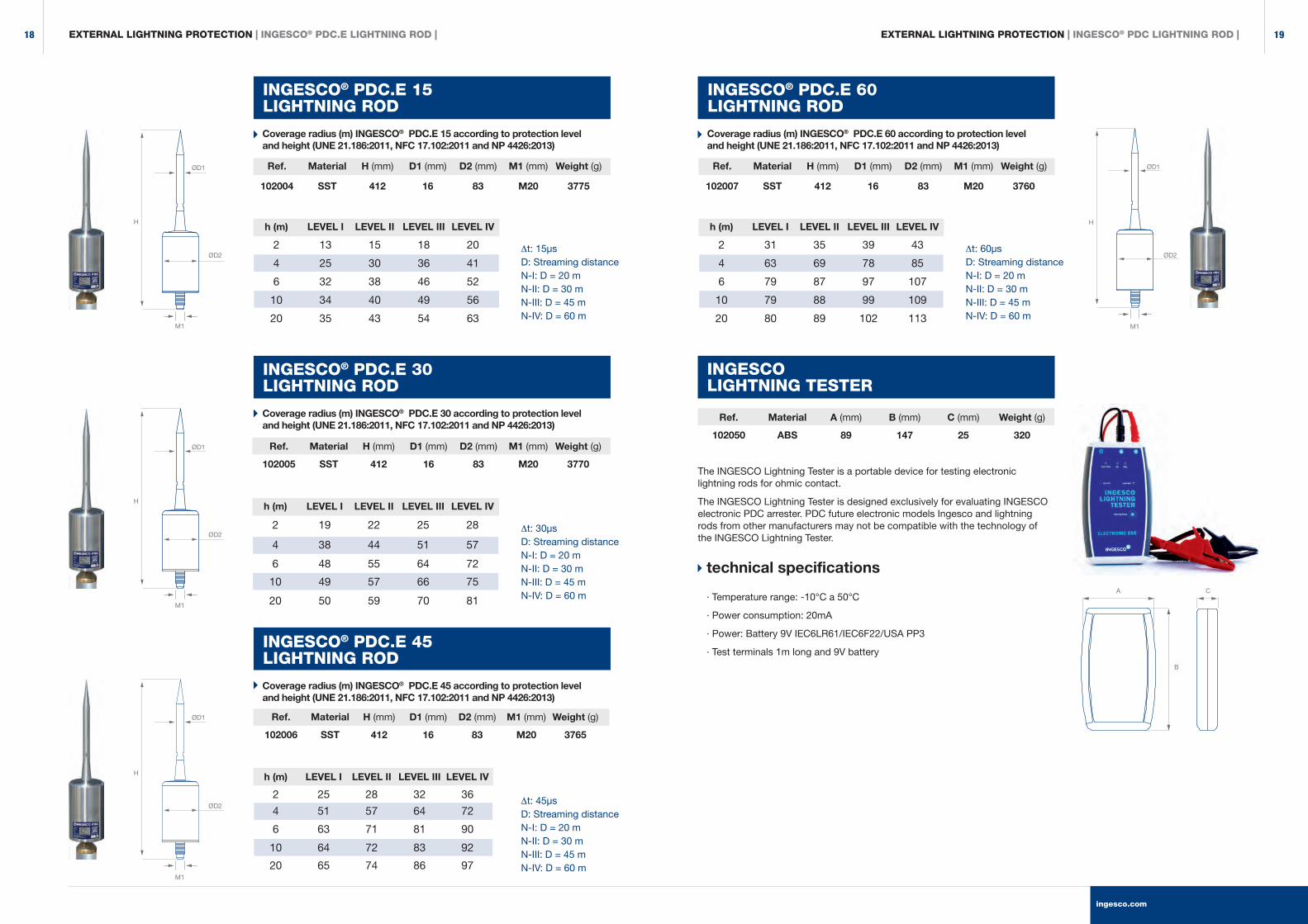
INGESCO® PDC.E 15LIGHTNING ROD
INGESCO® PDC.E 60LIGHTNING ROD
Coverage radius (m) INGESCO® PDC.E 15 according to protection level and height (UNE 21.186:2011, NFC 17.102:2011 and NP 4426:2013)
Coverage radius (m) INGESCO® PDC.E 60 according to protection level and height (UNE 21.186:2011, NFC 17.102:2011 and NP 4426:2013)
h (m)
2
4
6
10
20
LEVEL I
13
25
32
34
35
LEVEL II
15
30
38
40
43
LEVEL III
18
36
46
49
54
LEVEL IV
20
41
52
56
63
∆t: 15µsD: Streaming distanceN-I: D = 20 mN-II: D = 30 mN-III: D = 45 mN-IV: D = 60 m
∆t: 60µsD: Streaming distanceN-I: D = 20 mN-II: D = 30 mN-III: D = 45 mN-IV: D = 60 m
Ref.
102004
Material
SST
H (mm)
412
D1 (mm)
16
D2 (mm)
83
M1 (mm)
M20
Weight (g)
3775
h (m)
2
4
6
10
20
LEVEL I
31
63
79
79
80
LEVEL II
35
69
87
88
89
LEVEL III
39
78
97
99
102
LEVEL IV
43
85
107
109
113
Ref.
102007
Material
SST
H (mm)
412
D1 (mm)
16
D2 (mm)
83
M1 (mm)
M20
Weight (g)
3760
h (m)
2
4
6
10
20
LEVEL I
19
38
48
49
50
LEVEL II
22
44
55
57
59
LEVEL III
25
51
64
66
70
LEVEL IV
28
57
72
75
81
Ref.
102005
Material
SST
H (mm)
412
D1 (mm)
16
D2 (mm)
83
M1 (mm)
M20
Weight (g)
3770
INGESCOLIGHTNING TESTER
The INGESCO Lightning Tester is a portable device for testing electronic lightning rods for ohmic contact.
The INGESCO Lightning Tester is designed exclusively for evaluating INGESCO electronic PDC arrester. PDC future electronic models Ingesco and lightning rods from other manufacturers may not be compatible with the technology of the INGESCO Lightning Tester.
technical specifications
· Temperature range: -10°C a 50°C
· Power consumption: 20mA
· Power: Battery 9V IEC6LR61/IEC6F22/USA PP3
· Test terminals 1m long and 9V battery
Ref.
102050
Material
ABS
A (mm)
89
B (mm)
147
C (mm)
25
Weight (g)
320
h (m)
2
4
6
10
20
LEVEL I
25
51
63
64
65
LEVEL II
28
57
71
72
74
LEVEL III
32
64
81
83
86
LEVEL IV
36
72
90
92
97
Ref.
102006
Material
SST
H (mm)
412
D1 (mm)
16
D2 (mm)
83
M1 (mm)
M20
Weight (g)
3765
A C
B
EXTERNAL LIGHTNING PROTECTION | INGESCO® PDC.E LIGHTNING ROD |
H
ØD1
ØD2
M1
H
ØD1
ØD2
M1
H
ØD1
ØD2
M1
H
ØD1
ØD2
M1
INGESCO® PDC.E 30LIGHTNING ROD
INGESCO® PDC.E 45LIGHTNING ROD
Coverage radius (m) INGESCO® PDC.E 30 according to protection level and height (UNE 21.186:2011, NFC 17.102:2011 and NP 4426:2013)
Coverage radius (m) INGESCO® PDC.E 45 according to protection level and height (UNE 21.186:2011, NFC 17.102:2011 and NP 4426:2013)
∆t: 30µsD: Streaming distanceN-I: D = 20 mN-II: D = 30 mN-III: D = 45 mN-IV: D = 60 m
∆t: 45µsD: Streaming distanceN-I: D = 20 mN-II: D = 30 mN-III: D = 45 mN-IV: D = 60 m
EXTERNAL LIGHTNING PROTECTION | INGESCO® PDC LIGHTNING ROD |
ingesco.com
1918
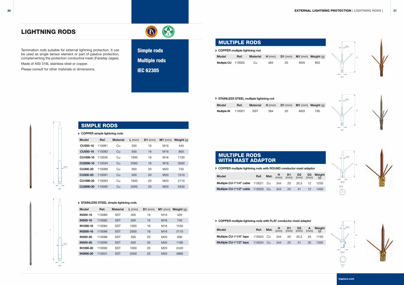
LIGHTNING RODS
SIMPLE RODS
Model
CU300-16
CU500-16
CU1000-16
CU2000-16
CU300-20
CU500-20
CU1000-20
CU2000-20
Ref.
110081
110083
110035
110034
110089
110091
110093
110095
Material
Cu
Cu
Cu
Cu
Cu
Cu
Cu
Cu
L (mm)
300
500
1000
2000
300
500
1000
2000
D1 (mm)
16
16
16
16
20
20
20
20
M1 (mm)
M16
M16
M16
M16
M20
M20
M20
M20
Weight (g)
440
800
1700
3500
740
1310
2710
5530
COPPER simple lightning rods
Model
IN300-16
IN500-16
IN1000-16
IN2000-16
IN300-20
IN500-20
IN1000-20
IN2000-20
Ref.
110080
110082
110084
110086
110088
110090
110092
110031
Material
SST
SST
SST
SST
SST
SST
SST
SST
L (mm)
300
500
1000
2000
300
500
1000
2000
D1 (mm)
16
16
16
16
20
20
20
20
M1 (mm)
M16
M16
M16
M16
M20
M20
M20
M20
Weight (g)
420
740
1530
3110
690
1180
2420
4880
STAINLESS STEEL simple lightning rods
Model
Multiple IN
Ref.
110001
Material
SST
H (mm)
384
D1 (mm)
20
M1 (mm)
M20
Weight (g)
795
STAINLESS STEEL multiple lightning rod
MULTIPLE RODS
Model
Multiple CU
Ref.
110002
Material
Cu
H (mm)
384
D1 (mm)
20
M1 (mm)
M20
Weight (g)
855
COPPER multiple lightning rodSimple rods
Multiple rods
IEC 62305
Termination rods suitable for external lightning protection. It can be used as single sensor element or part of passive protection, complementing the protection conductive mesh (Faraday cages).
Made of AISI 316L stainless steel or copper.
Please consult for other materials or dimensions.
MULTIPLE RODSWITH MAST ADAPTOR
110021
110020
Cu
Cu
H(mm)
344
344
D1(mm)
20
20
D2(mm)
35,5
41
D3(mm)
12
12
Weight(g)
1250
1400
110025
110024
Cu
Cu
H(mm)
344
344
D1(mm)
20
20
D2(mm)
35,5
41
A(mm)
25
30
Weight(g)
1150
1350
Multiple CU-1’1/4” cable
Multiple CU-1’1/2” cable
Multiple CU-1’1/4” tape
Multiple CU-1’1/2” tape
Model
Model
COPPER multiple lightning rods with ROUND conductor mast adaptor
COPPER multiple lightning rods with FLAT conductor mast adaptor
L
L
ØD1
ØD1
M1
M1
ØD1
ØD1
ØD1
ØD1
H
H
H
H
M1
M1
ØD2
ØD2
ØD3
A
Ref.
Ref.
Mat.
Mat.
EXTERNAL LIGHTNING PROTECTION | LIGHTNING RODS |
ingesco.com
2120

MULTIPLE RODSWITH MAST ADAPTER
Ref.
110019
110018
Mat.
SST
SST
H (mm)
344
344
D1 (mm)
20
20
D2 (mm)
35,5
41
D3 (mm)
12
12
1200
1350
Model
Multiple IN-1’1/4” cable
Multiple IN-1’1/2” cable
STAINLESS STEEL multiple lightning rods with ROUND conductor mast adapter
Ref.
110023
110022
Mat.
SST
SST
H (mm)
344
344
D1 (mm)
20
20
D2 (mm)
35,5
41
A (mm)
25
30
1100
1300
Model
Multiple IN-1’1/4” tape
Multiple IN-1’1/2” tape
STAINLESS STEEL multiple lightning rods with FLAT conductor mast adapter
SPECIAL LIGHTNING RODS
COPPER lightning rods with COPPER-PLATED STEEL horizontal support
COPPER lightning rods with GALVANIZED STEEL horizontal support
For application in electrical substations and others.
H(mm)
L(mm)
H2(mm)
D1(mm)
D2 (mm)
A(mm)
B(mm)
Weight(g)
H(mm)
L(mm)
H2(mm)
D1(mm)
D2 (mm)
A(mm)
B(mm)
Weight(g)
110003
110099
1584
2584
480
480
10
10
20
20
18
18
170
170
113
113
5500
8500
110096
110100
1584
2584
480
480
10
10
20
20
18
18
170
170
113
113
5600
5600
Adaptor parts
Masts
Fastening
CTE SUA 8
IEC 62305
IEC 62561
Accessories for installing the capture system. Adaptor parts, masts and anchoring systems.
Adjustment parts for lightning rods made by INGESCO (simple tips, multiple and ESE) of Ø16mm or 20mm. It facilitates the connection of the lightning rod to the conductive network.
Masts for fastening and support for termination rods to structures by anchors or baseplates.
Fastening systems for masts 1’1/4, 1’1/2 and 2” in diameter. Different solutions according to the construction needs.
Made of resistant materials such as brass, copper, galvanized iron and stainless steel.
Please consult for custom manufacturing and other construction.
CAPTURE SYSTEMACCESSORIESH
H
LIGHTNING ROD ADAPTER PIECES
Adapter parts for lightning rod to ROUND conductor mast
H(mm)
D1(mm)
D2(mm)
M1(mm)
Weight(g)
111033
111032
111022
111025
111019
111011
111012
111013
Cu/Zn
Cu/Zn
Cu/Zn
Cu/Zn
Cu/Zn
Cu/Zn
Cu/Zn
Cu/Zn
80
80
80
80
80
80
80
80
26
35,5
41
53
26
35,5
41
53
12
12
12
12
12
12
12
12
M16
M16
M16
M16
M20
M20
M20
M20
303
655
775
1305
288
640
760
1290
1” Ø16 round
1’1/4” Ø16 round
1’1/2” Ø16 round
2” Ø16 round
1” Ø20 round
1’1/4” Ø20 round
1’1/2” Ø20 round
2” Ø20 round
Adapter parts for lightning rod to FLAT conductor mast
H(mm)
D1(mm)
M1(mm)
A(mm)
B(mm)
Weight(g)
1’1/4” Ø16 tape
1’1/2” Ø16 tape
2” Ø16 tape
1’1/4” Ø20 tape
1’1/2” Ø20 tape
2” Ø20 tape
111035
111036
111037
117017
111014
111018
Cu/Zn
Cu/Zn
Cu/Zn
Cu/Zn
Cu/Zn
Cu/Zn
80
80
80
80
80
80
35,5
41
53
35,5
41
53
M16
M16
M16
M20
M20
M20
19
19
19
19
19
19
25
30
45
25
30
45
655
775
1305
640
760
1290
ØD1
H
H
A
M1
ØD2
ØD1
M1
B
Cu/ST Cu.
Cu/G.ST
Cu/ST Cu.
Cu/G.ST
ØD1
ØD1
ØD2
ØD3
ØD2
ØD1
ØD1
L
L
H
H
H2
H2
A
A
ØD2
B
A
A
ØD2
B
A
Ref.
Ref.
Model Mat.
Mat.Model
Model
Model
Ref.
Ref.
Mat.
Mat.
SE 1000 CU
SE 2000 CU
SE 1000 CU/AZ
SE 2000 CU/AZ
EXTERNAL LIGHTNING PROTECTION | LIGHTNING RODS |
Weight (g)
Weight (g)
ingesco.com
2322
H(mm)
M1(mm)
D1(mm)
M2(mm)
A(mm)
B(mm)
Weight(g)
H(mm)
M1(mm)
D1(mm)
M2(mm)
A(mm)
B(mm)
Weight(g)
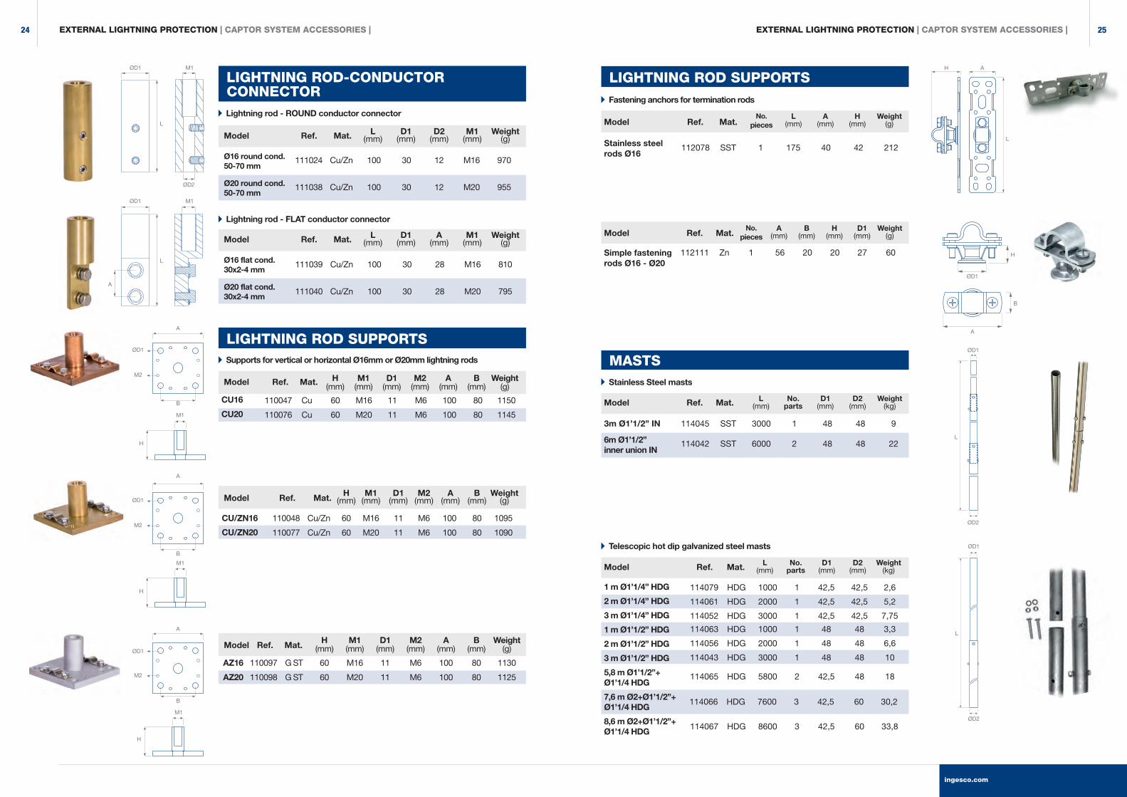
LIGHTNING ROD-CONDUCTOR CONNECTOR
Lightning rod - ROUND conductor connector
Lightning rod - FLAT conductor connector
L(mm)
D1(mm)
D2(mm)
M1(mm)
Weight(g)
L(mm)
D1(mm)
A(mm)
M1(mm)
Weight(g)
Model
Model
Model
Model
Model
111024
111038
Cu/Zn
Cu/Zn
100
100
30
30
12
12
M16
M20
970
955
111039
111040
Cu/Zn
Cu/Zn
100
100
30
30
28
28
M16
M20
810
795
LIGHTNING ROD SUPPORTS
110047
110076
Cu
Cu
60
60
M16
M20
11
11
M6
M6
100
100
80
80
1150
1145
AZ16
AZ20
110097
110098
G ST
G ST
60
60
M16
M20
11
11
M6
M6
100
100
80
80
1130
1125
Supports for vertical or horizontal Ø16mm or Ø20mm lightning rods
Ø16 round cond. 50-70 mm
Ø20 round cond. 50-70 mm
Ø16 flat cond. 30x2-4 mm
Ø20 flat cond. 30x2-4 mm
B
B
B
H
H
A
A
A
M1
M1
H
M1
M2
M2
M2
ØD1
ØD1
ØD1
ØD1
ØD2
L
L
ØD1
A
M1
M1
Telescopic hot dip galvanized steel masts
L(mm)
No.parts
D1(mm)
D2(mm)
Weight(kg)
1 m Ø1’1/4” HDG
2 m Ø1’1/4” HDG
3 m Ø1’1/4” HDG
1 m Ø1’1/2” HDG
2 m Ø1’1/2” HDG
3 m Ø1’1/2” HDG
5,8 m Ø1’1/2”+ Ø1’1/4 HDG
7,6 m Ø2+Ø1’1/2”+ Ø1’1/4 HDG
8,6 m Ø2+Ø1’1/2”+ Ø1’1/4 HDG
MASTS
LIGHTNING ROD SUPPORTS
112078 SST 1 175 40 42 212Stainless steel rods Ø16
Fastening anchors for termination rods
Simple fasteningrods Ø16 - Ø20
Stainless Steel masts
114045
114042
SST
SST
3000
6000
1
2
48
48
48
48
9
22
3m Ø1’1/2” IN
6m Ø1’1/2” inner union IN
L(mm)
No.parts
D1(mm)
D2(mm)
Weight(kg)
CU/ZN16
CU/ZN20
110048 Cu/Zn 60 M16 11 M6 100 80 1095
110077 Cu/Zn 60 M20 11 M6 100 80 1090
H M1 D1 M2 A B Weight (mm) (mm) (mm) (mm) (mm) (mm) (g)
H A
L
H
ØD1
A
ØD1
ØD1
ØD2
ØD2
L
L
B
114079 HDG 1000 1 42,5 42,5 2,6
114061 HDG 2000 1 42,5 42,5 5,2
114052 HDG 3000 1 42,5 42,5 7,75
114063 HDG 1000 1 48 48 3,3
114056 HDG 2000 1 48 48 6,6
114043 HDG 3000 1 48 48 10
114065 HDG 5800 2 42,5 48 18
114066 HDG 7600 3 42,5 60 30,2
114067 HDG 8600 3 42,5 60 33,8
Ref.
Ref.
Ref.
Ref.
Ref.
Mat.
No. pieces
A(mm)
B(mm)
H(mm)
D1(mm)
Weight(g)Model Ref. Mat.
No. pieces
L(mm)
A(mm)
H(mm)
Weight(g)Model Ref. Mat.
Mat.
Mat.
Mat.
Mat.
Model
Model
Ref.
Ref.
Mat.
Mat.
CU16
CU20
EXTERNAL LIGHTNING PROTECTION | CAPTOR SYSTEM ACCESSORIES | EXTERNAL LIGHTNING PROTECTION | CAPTOR SYSTEM ACCESSORIES |
112111 Zn 1 56 20 20 27 60
ingesco.com
2524

Øtubes L (inches) parts (m)
FREE-STANDING FOLDING MASTS
Self-supporting folding mast. Attachable sections, folding hinged baseplate. Easy transport and assembly. Dimensioned to withstand winds up to 144 Km / h.
Free-standing hot dip galvanized steel masts
A
WIND KIT Wind kit for fastening masts
Model
Model
Wind kit fastening masts
MASTS Hot dip galvanized steel masts with internal junction
L(mm)
No.parts
D1(mm)
D2(mm)
Weight(kg)
114048 HDG 6 2 42,5 42,5 16,86 m Ø1’1/4” inner union HDG
6 m Ø1’1/2” inner union HDG
8 m Ø2+Ø1’1/2”+ Ø1’1/4 inner union HDG
9 m Ø2+Ø1’1/2”+ Ø1’1/4 inner union HDG
114041 HDG 6 2 48 48 23
114068 HDG 8 3 42,5 60 33,8
114069 HDG 9 3 42,5 60 36,9
114197 HDG 40 45 120º 25 3 6 500
D1 D2 m.steel No. No. cable Weight (mm) (mm) cable tighteners ties (g)
L
ØD1
ØD2
ØD1S.6
S.5
S.4
S.3
S.2
S.1
ØD
2
No.pieces
L(mm)
A(mm)
B(mm)
C(mm)
No.pieces
L(mm)
A(mm)
B(mm)
C(mm)
E(mm)
work anchor 30 mast Ø1’1/4”
work anchor 30 mast Ø1’1/2”
work anchor 30 mast Ø2”
112088
112021
112038
HDG
HDG
HDG
2
2
2
395
395
395
46
60
72
35
35
35
100
100
100
5
5,2
5,4
work anchor 60 mast Ø1’1/4”
work anchor 60 mast Ø1’1/2”
work anchor 30 mast Ø2”
112089
112022
112040
HDG
HDG
HDG
2
2
2
700
700
700
46
60
72
35
35
35
270
270
270
395
395
395
13
13,2
13,4
No.pieces
L(mm)
A(mm)
B(mm)
C(mm)
E(mm)
work anchor 100 mast Ø1’1/4”
work anchor 100 mast Ø1’1/2”
work anchor 100 mast Ø2”
112090
112023
112042
HDG
HDG
HDG
2
2
2
1095
1095
1095
46
60
72
35
35
35
365
365
365
460
460
460
23,4
23,6
23,8
ANCHORS AND SUPPORTS FOR MASTS
Anchors for vertically embedded wall mounting
No.pieces
L(mm)
A(mm)
B(mm)
C(mm)
Weight(kg)
work anchor 15 mast Ø1’1/4”
work anchor 15 mast Ø1’1/2”
work anchor 15 mast Ø2”
112087
112071
112096
HDG
HDG
HDG
2
2
2
240
240
240
46
60
72
35
35
35
110
110
110
3,6
3,8
4
L
A
C
B
L
A
C
E
S.1 4” 3
S.2 3” 2,5
S.3 2’1/2” 2,5
S.4 1’1/2” 2
S.1 5” 3
S.2 4” 2,5
S.3 3” 2,5
S.4 2’1/2” 2,5
S.5 1’1/2” 1,5
S.1 6” 3
S.2 5” 2,5
S.3 4” 2,5
S.4 3” 2,5
S.5 2’1/2” 2,5
S.6 1’1/2” 1
10 m 114075 HDG 10 48 500 125
12 m 114076 HDG 12 48 500 160
14 m 114078 HDG 14 48 500 212
H
Model
Model
Model
Model
Model
Ref.
Ref.
Ref.
Ref.
Ref.
Ref.
Ref.
Mat.
Mat.
Mat.
Mat.
Mat.
Mat. α
Mat. Secc. Weight
EXTERNAL LIGHTNING PROTECTION | CAPTOR SYSTEM ACCESSORIES | EXTERNAL LIGHTNING PROTECTION | CAPTOR SYSTEM ACCESSORIES |
Weight(kg)
Weight(kg)
Weight(kg)
ingesco.com
2726
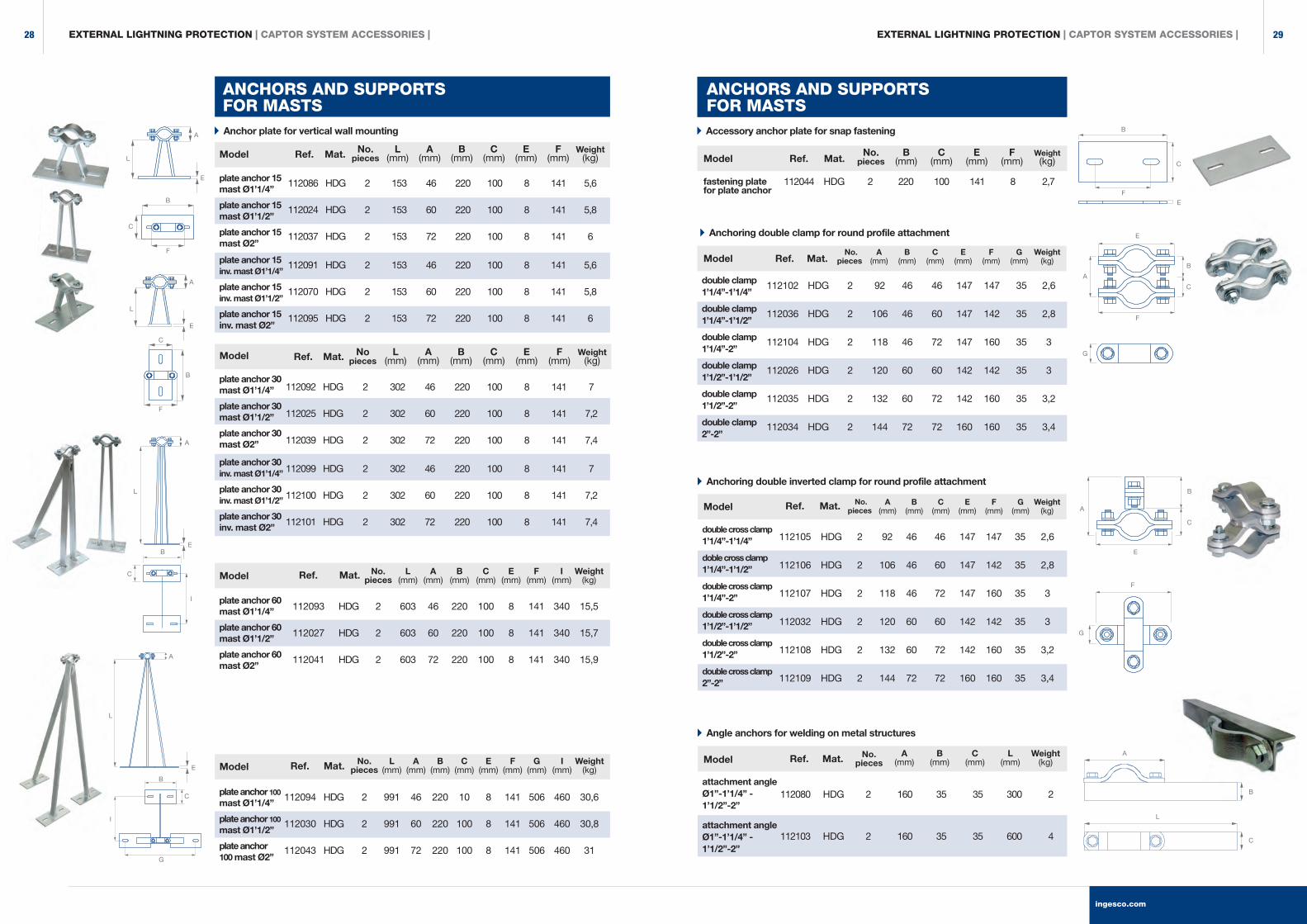
Anchor plate for vertical wall mounting
No.pieces
L(mm)
A(mm)
B(mm)
C(mm)
E(mm)
F(mm)
Weight(kg)
plate anchor 15 mast Ø1’1/4”
plate anchor 15 mast Ø1’1/2”
plate anchor 15 mast Ø2”
112086
112024
112037
HDG
HDG
HDG
2
2
2
153
153
153
46
60
72
220
220
220
100
100
100
8
8
8
141
141
141
5,6
5,8
6
plate anchor 15 inv. mast Ø1’1/4”
plate anchor 15 inv. mast Ø1’1/2”
plate anchor 15 inv. mast Ø2”
112091
112070
112095
HDG
HDG
HDG
2
2
2
153
153
153
46
60
72
220
220
220
100
100
100
8
8
8
141
141
141
5,6
5,8
6
Nopieces
L(mm)
A(mm)
B(mm)
C(mm)
E(mm)
F(mm)
Weight(kg)
plate anchor 30 mast Ø1’1/4”
plate anchor 30 mast Ø1’1/2”
plate anchor 30 mast Ø2”
112092
112025
112039
HDG
HDG
HDG
2
2
2
302
302
302
46
60
72
220
220
220
100
100
100
8
8
8
141
141
141
7
7,2
7,4
plate anchor 30 inv. mast Ø1’1/4”
plate anchor 30 inv. mast Ø1’1/2”
plate anchor 30 inv. mast Ø2”
112099
112100
112101
HDG
HDG
HDG
2
2
2
302
302
302
46
60
72
220
220
220
100
100
100
8
8
8
141
141
141
7
7,2
7,4
plate anchor 60 mast Ø1’1/4”
plate anchor 60 mast Ø1’1/2”
plate anchor 60 mast Ø2”
plate anchor 100 mast Ø1’1/4”
plate anchor 100 mast Ø1’1/2”
plate anchor 100 mast Ø2”
ANCHORS AND SUPPORTS FOR MASTS
ANCHORS AND SUPPORTS FOR MASTS
Accessory anchor plate for snap fastening
No.pieces
B(mm)
C(mm)
E(mm)
F(mm)
Weight(kg)
112044 HDG 2 220 100 141 8 2,7fastening plate for plate anchor
Anchoring double clamp for round profile attachment
No.pieces
A(mm)
B(mm)
C(mm)
E(mm)
F(mm)
G(mm)
Weight(kg)
double clamp 1’1/4”-1’1/4”
double clamp 1’1/4”-1’1/2”
double clamp 1’1/4”-2”
double clamp 1’1/2”-1’1/2”
double clamp 1’1/2”-2”
double clamp 2”-2”
Anchoring double inverted clamp for round profile attachment
No.pieces
A(mm)
B(mm)
C(mm)
E(mm)
F(mm)
G(mm)
Weight(kg)
double cross clamp 1’1/4”-1’1/4”
doble cross clamp 1’1/4”-1’1/2”
double cross clamp 1’1/4”-2”
double cross clamp 1’1/2”-1’1/2”
double cross clamp 1’1/2”-2”
double cross clamp 2”-2”
Angle anchors for welding on metal structures
No.pieces
A(mm)
B(mm)
C(mm)
L(mm)
Weight(kg)
attachment angle Ø1”-1’1/4” - 1’1/2”-2”
attachment angle Ø1”-1’1/4” - 1’1/2”-2”
112080
112103
HDG
HDG
2
2
160
160
35
35
35
35
300
600
2
4
B
F
A
L
B
C
G
F
E
A
B
C
F
E
A
G
B
C
E
C
A
L
C
B
F
A
L
E
E
E
C
B
F
E
A
L
I
C
B
G
A
L
I
B
C
112093 HDG 2 603 46 220 100 8 141 340 15,5
112027 HDG 2 603 60 220 100 8 141 340 15,7
112041 HDG 2 603 72 220 100 8 141 340 15,9
112094 HDG 2 991 46 220 10 8 141 506 460 30,6
112030 HDG 2 991 60 220 100 8 141 506 460 30,8
112043 HDG 2 991 72 220 100 8 141 506 460 31
112102 HDG 2 92 46 46 147 147 35 2,6
112036 HDG 2 106 46 60 147 142 35 2,8
112104 HDG 2 118 46 72 147 160 35 3
112026 HDG 2 120 60 60 142 142 35 3
112035 HDG 2 132 60 72 142 160 35 3,2
112034 HDG 2 144 72 72 160 160 35 3,4
112105 HDG 2 92 46 46 147 147 35 2,6
112106 HDG 2 106 46 60 147 142 35 2,8
112107 HDG 2 118 46 72 147 160 35 3
112032 HDG 2 120 60 60 142 142 35 3
112108 HDG 2 132 60 72 142 160 35 3,2
112109 HDG 2 144 72 72 160 160 35 3,4
No. L A B C E F I Weight pieces (mm) (mm) (mm) (mm) (mm) (mm) (mm) (kg)
No. L A B C E F G I Weight pieces (mm) (mm) (mm) (mm) (mm) (mm) (mm) (mm) (kg)
Model Model
Model
Model
Model
Model
Model
Model
Ref. Ref.
Ref.
Ref.
Ref.
Ref.
Ref.
Ref.
Mat. Mat.
Mat.
Mat.
Mat.
Mat.
Mat.
Mat.
EXTERNAL LIGHTNING PROTECTION | CAPTOR SYSTEM ACCESSORIES | EXTERNAL LIGHTNING PROTECTION | CAPTOR SYSTEM ACCESSORIES |
ingesco.com
2928
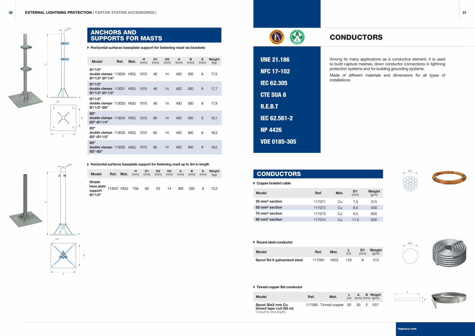
ANCHORS AND SUPPORTS FOR MASTS
Horizontal surfaces baseplate support for fastening mast up to 3m in length
H(mm)
D1(mm)
D2(mm)
D3(mm)
A(mm)
B(mm)
E(mm)
Weight(kg)
Simple base plate supportØ1’1/2”
113037 HDG 758 60 53 14 300 260 8 12,5
Horizontal surfaces baseplate support for fastening mast via brackets
H(mm)
D1(mm)
D2(mm)
A(mm)
B(mm)
E(mm)
Weight (kg)
Ø1’1/2” double clamps Ø1’1/2”-Ø1’1/4”
Ø1’1/2” double clamps Ø1’1/2”-Ø1’1/2”
Ø1’1/2” double clamps Ø1’1/2”-Ø2”
Ø2” double clamps Ø2”-Ø1’1/4”
Ø2” double clamps Ø2”-Ø1’1/2”
Ø2” double clamps Ø2”-Ø2”
113034
113031
113033
113043
113035
113032
HDG
HDG
HDG
HDG
HDG
HDG
1015
1015
1015
1015
1015
1015
48
48
48
60
60
60
14
14
14
14
14
14
400
400
400
400
400
400
300
300
300
300
300
300
8
8
8
8
8
8
17,5
17,7
17,9
18,1
18,3
18,5
Spool 30x2 mm Cu tinned tape coil (50 m)*consult for other lengths
Tinned copper flat conductor
L A B Weight (m) (mm) (mm) (g/m)
117082 Tinned copper 50 30 2 537
UNE 21.186
NFC 17-102
IEC 62.305
CTE SUA 8
R.E.B.T
IEC 62.561-2
NP 4426
VDE 0185-305
Among its many applications as a conductive element, it is used to build capture meshes, down conductor connections in lightning protection systems and for building grounding systems.
Made of different materials and dimensions for all types of installations.
CONDUCTORSØD1
H
D2
B
A
E
ØD1ØD2
H
D3
B
A
E
CONDUCTORS Copper braided cable
35 mm² section
50 mm² section
70 mm² section
95 mm² section
117071 Cu 7,5 315
117072 Cu 8,5 500
117073 Cu 9,5 600
117074 Cu 11,5 830
ØD1
Spool Rd 8 galvanized steel
Round steel conductor
L D1 Weight (m) (mm) (g/m)
D1 Weight (mm) (g/m)
117081 HDG 125 8 312
ØD1
B
A
Model
Model
Ref.
Ref.
Mat.
Mat.
Model
Model
Model
Ref.
Ref.
Ref.
Mat.
Mat.
Mat.
EXTERNAL LIGHTNING PROTECTION | CAPTOR SYSTEM ACCESSORIES |
ingesco.com
3130
Clamps
Connectors
IEC 62.305
IEC 62.561-4
UNE 21.186
NFC 17-102
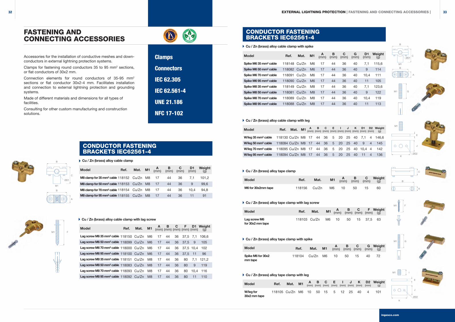
Accessories for the installation of conductive meshes and down-conductors in external lightning protection systems.
Clamps for fastening round conductors 35 to 95 mm2 sections, or flat conductors of 30x2 mm.
Connection elements for round conductors of 35-95 mm2
sections or flat conductor 30x2-4 mm. Facilitates installation and connection to external lightning protection and grounding systems.
Made of different materials and dimensions for all types of facilities.
Consulting for other custom manufacturing and construction solutions.
FASTENING AND CONNECTING ACCESSORIES
EXTERNAL LIGHTNING PROTECTION | FASTENING AND CONNECTING ACCESSORIES |
Cu / Zn (brass) alloy tape clamp with leg
W/leg for 30x2 mm tape
118105 Cu/Zn M6 10 50 15 5 12 25 40 4 101
A B C E I J K D2 Weight (mm) (mm) (mm) (mm) (mm) (mm) (mm) (mm) (g)
Spike M6 35 mm² cable
Spike M6 50 mm² cable
Spike M6 70 mm² cable
Spike M6 95 mm² cable
Spike M8 35 mm² cable
Spike M8 50 mm² cable
Spike M8 70 mm² cable
Spike M8 95 mm² cable
118148 Cu/Zn M6 17 44 36 40 7,1 115,6
118082 Cu/Zn M6 17 44 36 40 9 114
118091 Cu/Zn M6 17 44 36 40 10,4 111
118090 Cu/Zn M6 17 44 36 40 11 105
118149 Cu/Zn M8 17 44 36 40 7,1 123,6
118081 Cu/Zn M8 17 44 36 40 9 122
118089 Cu/Zn M8 17 44 36 40 10,4 119
118088 Cu/Zn M8 17 44 36 40 11 113
A B C G D1 Weight (mm) (mm) (mm) (mm) (mm) (g)
Cu / Zn (brass) alloy cable clamp with spike
CONDUCTOR FASTENING BRACKETS IEC62561-4
GM1
Cu / Zn (brass) alloy tape clamp
M6 for 30x2mm tape 118156 Cu/Zn M6 10 50 15 60
A B C Weight (mm) (mm) (mm) (g)
C
B
A
Cu / Zn (brass) alloy tape clamp with lag screw
Lag screw M6 for 30x2 mm tape
118103 Cu/Zn M6 10 50 15 37,5 63
A B C F Weight (mm) (mm) (mm) (mm) (g)
FM1
Cu / Zn (brass) alloy tape clamp with spike
A B C G Weight (mm) (mm) (mm) (mm) (g)
Spike M6 for 30x2 mm tape
118104 Cu/Zn M6 10 50 15 40 72
GM1
IM1
E
ØD2
J
K
W/leg 35 mm² cable
W/leg 50 mm² cable
W/leg 70 mm² cable
W/leg 95 mm² cable
118130 Cu/Zn M8 17 44 36 5 20 25 40 7,1 4 146,6
118084 Cu/Zn M8 17 44 36 5 20 25 40 9 4 145
118095 Cu/Zn M8 17 44 36 5 20 25 40 10,4 4 142
118094 Cu/Zn M8 17 44 36 5 20 25 40 11 4 136
A B C E I J K D1 D2 Weight (mm) (mm) (mm) (mm) (mm) (mm) (mm) (mm) (mm) (g)
Cu / Zn (brass) alloy cable clamp with leg
E
J
K
M1
Cu / Zn (brass) alloy cable clamp with lag screw
Lag screw M6 35 mm² cable
Lag screw M6 50 mm² cable
Lag screw M6 70 mm² cable
Lag screw M6 95 mm² cable
Lag screw M8 35 mm² cable
Lag screw M8 50 mm² cable
Lag screw M8 70 mm² cable
Lag screw M8 95 mm² cable
118150 Cu/Zn M6 17 44 36 37,5 7,1 106,6
118099 Cu/Zn M6 17 44 36 37,5 9 105
118000 Cu/Zn M6 17 44 36 37,5 10,4 102
118100 Cu/Zn M6 17 44 36 37,5 11 96
118151 Cu/Zn M8 17 44 36 80 7,1 121,2
118083 Cu/Zn M8 17 44 36 80 9 119
118093 Cu/Zn M8 17 44 36 80 10,4 116
118092 Cu/Zn M8 17 44 36 80 11 110
A B C F D1 Weight (mm) (mm) (mm) (mm) (mm) (g)
Cu / Zn (brass) alloy cable clamp
M8 clamp for 35 mm² cable
M8 clamp for 50 mm² cable
M8 clamp for 70 mm² cable
M8 clamp for 95 mm² cable
118152 Cu/Zn M8 17 44 36 7,1 101,2
118153 Cu/Zn M8 17 44 36 9 99,6
118154 Cu/Zn M8 17 44 36 10,4 94,8
118155 Cu/Zn M8 17 44 36 11 91
A B C D1 Weight (mm) (mm) (mm) (mm) (g)
CONDUCTOR FASTENING BRACKETS IEC62561-4
B
ØD1
C
A
B
M1
B
ØD1C
A
B
M1
FM1
Model
Model
Model
Model
Model
Model
Model
Model
Ref.
Ref.
Ref.
Ref.
Ref.
Ref.
Ref.
Ref.
Mat.
Mat.
Mat.
Mat.
Mat.
Mat.
Mat.
Mat.
M1
M1
M1
M1
M1
M1
M1
M1
ØD2
ingesco.com
3332
EXTERNAL LIGHTNING PROTECTION | FASTENING AND CONNECTING ACCESSORIES |
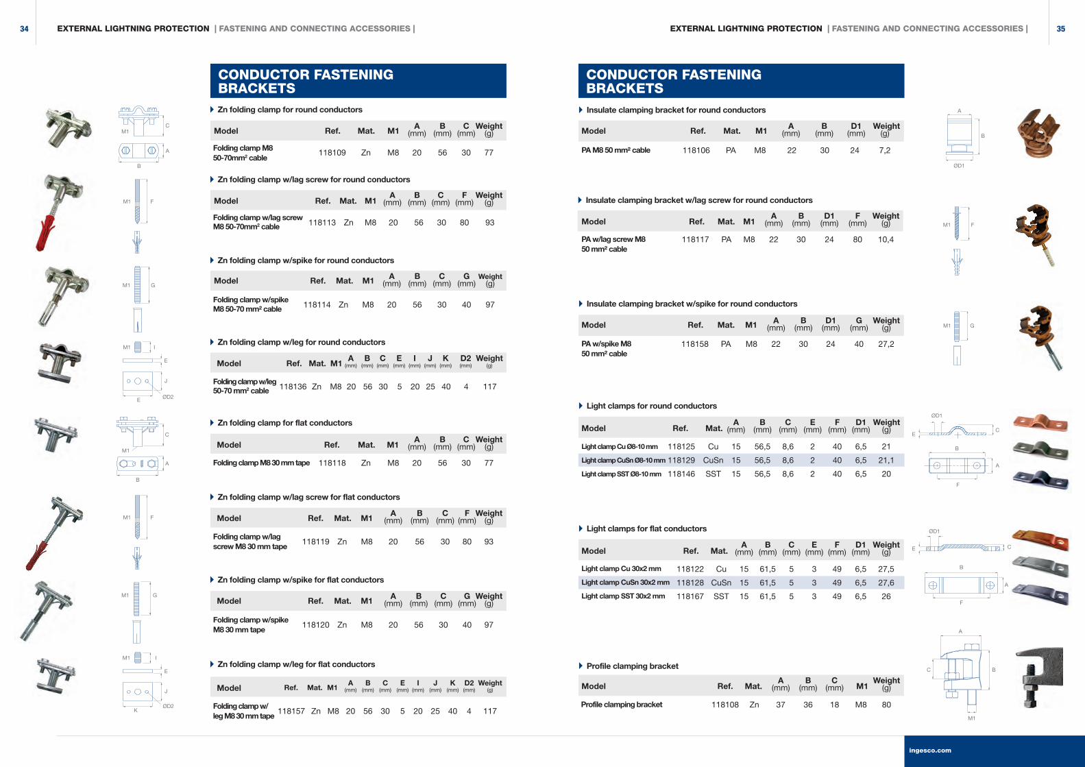
Zn folding clamp for round conductors
Zn folding clamp for flat conductors
Zn folding clamp w/lag screw for flat conductors
Zn folding clamp w/spike for flat conductors
Zn folding clamp w/leg for flat conductors
Folding clamp M8 50-70mm2 cable
Folding clamp M8 30 mm tape
Folding clamp w/lag screw M8 30 mm tape
Folding clamp w/spike M8 30 mm tape
Folding clamp w/leg M8 30 mm tape
118109 Zn M8 20 56 30 77
118118 Zn M8 20 56 30 77
118119 Zn M8 20 56 30 80 93
118120 Zn M8 20 56 30 40 97
118157 Zn M8 20 56 30 5 20 25 40 4 117
A B C Weight (mm) (mm) (mm) (g)
A B C Weight (mm) (mm) (mm) (g)
Zn folding clamp w/lag screw for round conductors
Folding clamp w/lag screw M8 50-70mm2 cable 118113 Zn M8 20 56 30 80 93
A B C F Weight (mm) (mm) (mm) (mm) (g)
A B C F Weight (mm) (mm) (mm) (mm) (g)
Zn folding clamp w/spike for round conductors
Folding clamp w/spikeM8 50-70 mm² cable 118114 Zn M8 20 56 30 40 97
A B C G Weight (mm) (mm) (mm) (mm) (g)
A B C G Weight (mm) (mm) (mm) (mm) (g)
Zn folding clamp w/leg for round conductors
Folding clamp w/leg 50-70 mm2 cable 118136 Zn M8 20 56 30 5 20 25 40 4 117
A B C E I J K D2 Weight (mm) (mm) (mm) (mm) (mm) (mm) (mm) (mm) (g)
A B C E I J K D2 Weight (mm) (mm) (mm) (mm) (mm) (mm) (mm) (mm) (g)
Insulate clamping bracket for round conductors
PA M8 50 mm² cable 118106 PA M8 22 30 24 7,2
A B D1 Weight (mm) (mm) (mm) (g)
Insulate clamping bracket w/spike for round conductors
PA w/spike M8 50 mm² cable
118158 PA M8 22 30 24 40 27,2
A B D1 G Weight (mm) (mm) (mm) (mm) (g)
Light clamps for round conductors
Light clamp Cu Ø8-10 mm
Light clamp CuSn Ø8-10 mm
Light clamp SST Ø8-10 mm
118125 Cu 15 56,5 8,6 2 40 6,5 21
118129 CuSn 15 56,5 8,6 2 40 6,5 21,1
118146 SST 15 56,5 8,6 2 40 6,5 20
A B C E F D1 Weight (mm) (mm) (mm) (mm) (mm) (mm) (g)
Light clamps for flat conductors
Light clamp Cu 30x2 mm
Light clamp CuSn 30x2 mm
Light clamp SST 30x2 mm
118122 Cu 15 61,5 5 3 49 6,5 27,5
118128 CuSn 15 61,5 5 3 49 6,5 27,6
118167 SST 15 61,5 5 3 49 6,5 26
A B C E F D1 Weight (mm) (mm) (mm) (mm) (mm) (mm) (g)
Profile clamping bracket
Profile clamping bracket 118108 Zn 37 36 18 M8 80
A B C Weight (mm) (mm) (mm) (g)
EXTERNAL LIGHTNING PROTECTION | FASTENING AND CONNECTING ACCESSORIES |
CONDUCTOR FASTENING BRACKETS
CONDUCTOR FASTENING BRACKETS
C
A
B
M1
F
G
M1
M1
A
B
C
IM1
E
J
ØD2K
M1
E
J
E ØD2
I
A
B
ØD1
A
C B
M1
ØD1
B
F
E C
B
ØD1
F
EC
A
A
M1
GM1
Insulate clamping bracket w/lag screw for round conductors
PA w/lag screw M8 50 mm² cable
118117 PA M8 22 30 24 80 10,4
A B D1 F Weight (mm) (mm) (mm) (mm) (g)
GM1
Model Model
Model
Model
Model
Model
Model
Model
Model
Model
Model
Model
Model
Model
Ref. Ref.
Ref.
Ref.
Ref.
Ref.
Ref.
Ref.
Ref.
Ref.
Ref.
Ref.
Ref.
Ref.
Mat. Mat.
Mat.
Mat.
Mat.
Mat.
Mat.
M1
M1
M1
Mat.
Mat.
Mat.
Mat.
Mat.
Mat.
Mat.
M1
M1
M1
M1
M1
M1
M1
M1
FM1
FM1
M1
ingesco.com
3534
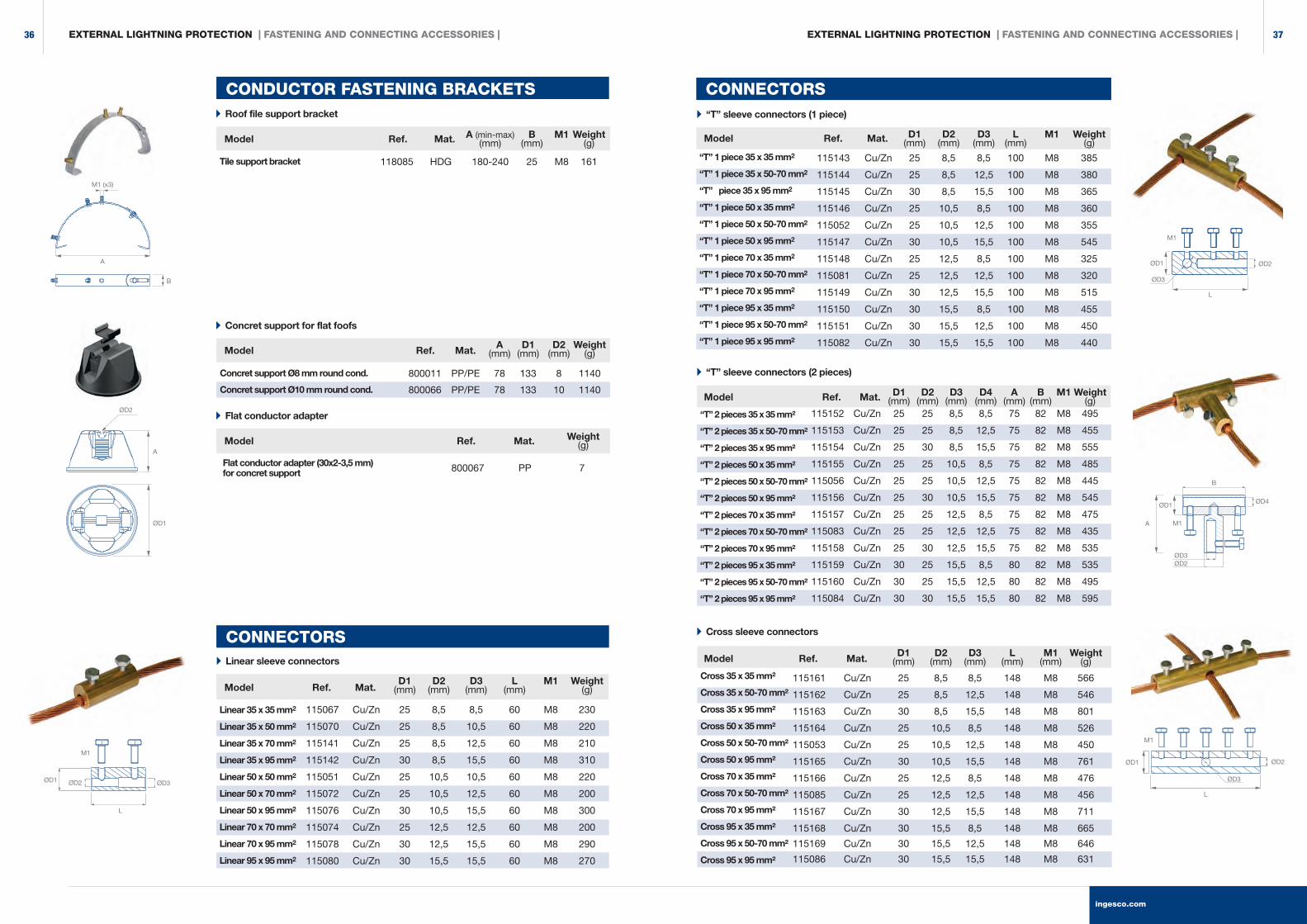
“T” sleeve connectors (2 pieces)
Concret support for flat foofs
Flat conductor adapter
Concret support Ø8 mm round cond.
Concret support Ø10 mm round cond.
Flat conductor adapter (30x2-3,5 mm)for concret support
800011 PP/PE 78 133 8 1140
800066 PP/PE 78 133 10 1140
800067 PP 7
A D1 D2 Weight (mm) (mm) (mm) (g)
Weight (g)
“T” sleeve connectors (1 piece)
CONNECTORS
“T” 1 piece 35 x 35 mm2
“T” 1 piece 35 x 50-70 mm2
“T” piece 35 x 95 mm2
“T” 1 piece 50 x 35 mm2
“T” 1 piece 50 x 50-70 mm2
“T” 1 piece 50 x 95 mm2
“T” 1 piece 70 x 35 mm2
“T” 1 piece 70 x 50-70 mm2
“T” 1 piece 70 x 95 mm2
“T” 1 piece 95 x 35 mm2
“T” 1 piece 95 x 50-70 mm2
“T” 1 piece 95 x 95 mm2
115143 Cu/Zn 25 8,5 8,5 100 M8 385
115144 Cu/Zn 25 8,5 12,5 100 M8 380
115145 Cu/Zn 30 8,5 15,5 100 M8 365
115146 Cu/Zn 25 10,5 8,5 100 M8 360
115052 Cu/Zn 25 10,5 12,5 100 M8 355
115147 Cu/Zn 30 10,5 15,5 100 M8 545
115148 Cu/Zn 25 12,5 8,5 100 M8 325
115081 Cu/Zn 25 12,5 12,5 100 M8 320
115149 Cu/Zn 30 12,5 15,5 100 M8 515
115150 Cu/Zn 30 15,5 8,5 100 M8 455
115151 Cu/Zn 30 15,5 12,5 100 M8 450
115082 Cu/Zn 30 15,5 15,5 100 M8 440
D1 D2 D3 L M1 Weight (mm) (mm) (mm) (mm) (g)
“T” 2 pieces 35 x 35 mm²
“T” 2 pieces 35 x 50-70 mm²
“T” 2 pieces 35 x 95 mm²
“T” 2 pieces 50 x 35 mm²
“T” 2 pieces 50 x 50-70 mm²
“T” 2 pieces 50 x 95 mm²
“T” 2 pieces 70 x 35 mm²
“T” 2 pieces 70 x 50-70 mm²
“T” 2 pieces 70 x 95 mm²
“T” 2 pieces 95 x 35 mm²
“T” 2 pieces 95 x 50-70 mm²
“T” 2 pieces 95 x 95 mm²
115152 Cu/Zn 25 25 8,5 8,5 75 82 M8 495
115153 Cu/Zn 25 25 8,5 12,5 75 82 M8 455
115154 Cu/Zn 25 30 8,5 15,5 75 82 M8 555
115155 Cu/Zn 25 25 10,5 8,5 75 82 M8 485
115056 Cu/Zn 25 25 10,5 12,5 75 82 M8 445
115156 Cu/Zn 25 30 10,5 15,5 75 82 M8 545
115157 Cu/Zn 25 25 12,5 8,5 75 82 M8 475
115083 Cu/Zn 25 25 12,5 12,5 75 82 M8 435
115158 Cu/Zn 25 30 12,5 15,5 75 82 M8 535
115159 Cu/Zn 30 25 15,5 8,5 80 82 M8 535
115160 Cu/Zn 30 25 15,5 12,5 80 82 M8 495
115084 Cu/Zn 30 30 15,5 15,5 80 82 M8 595
D1 D2 D3 D4 A B M1 Weight (mm) (mm) (mm) (mm) (mm) (mm) (g)
Cross sleeve connectors
Cross 35 x 35 mm²
Cross 35 x 50-70 mm²
Cross 35 x 95 mm²
Cross 50 x 35 mm²
Cross 50 x 50-70 mm²
Cross 50 x 95 mm²
Cross 70 x 35 mm²
Cross 70 x 50-70 mm²
Cross 70 x 95 mm²
Cross 95 x 35 mm²
Cross 95 x 50-70 mm²
Cross 95 x 95 mm²
115161 Cu/Zn 25 8,5 8,5 148 M8 566
115162 Cu/Zn 25 8,5 12,5 148 M8 546
115163 Cu/Zn 30 8,5 15,5 148 M8 801
115164 Cu/Zn 25 10,5 8,5 148 M8 526
115053 Cu/Zn 25 10,5 12,5 148 M8 450
115165 Cu/Zn 30 10,5 15,5 148 M8 761
115166 Cu/Zn 25 12,5 8,5 148 M8 476
115085 Cu/Zn 25 12,5 12,5 148 M8 456
115167 Cu/Zn 30 12,5 15,5 148 M8 711
115168 Cu/Zn 30 15,5 8,5 148 M8 665
115169 Cu/Zn 30 15,5 12,5 148 M8 646
115086 Cu/Zn 30 15,5 15,5 148 M8 631
D1 D2 D3 L M1 Weight (mm) (mm) (mm) (mm) (mm) (g)
Roof file support bracket
Tile support bracket 118085 HDG 180-240 25 M8 161
A (min-max) B M1 Weight (mm) (mm) (g)
CONDUCTOR FASTENING BRACKETS
CONNECTORS Linear sleeve connectors
Linear 35 x 35 mm2
Linear 35 x 50 mm2
Linear 35 x 70 mm2
Linear 35 x 95 mm2
Linear 50 x 50 mm2
Linear 50 x 70 mm2
Linear 50 x 95 mm2
Linear 70 x 70 mm2
Linear 70 x 95 mm2
Linear 95 x 95 mm2
115067 Cu/Zn 25 8,5 8,5 60 M8 230
115070 Cu/Zn 25 8,5 10,5 60 M8 220
115141 Cu/Zn 25 8,5 12,5 60 M8 210
115142 Cu/Zn 30 8,5 15,5 60 M8 310
115051 Cu/Zn 25 10,5 10,5 60 M8 220
115072 Cu/Zn 25 10,5 12,5 60 M8 200
115076 Cu/Zn 30 10,5 15,5 60 M8 300
115074 Cu/Zn 25 12,5 12,5 60 M8 200
115078 Cu/Zn 30 12,5 15,5 60 M8 290
115080 Cu/Zn 30 15,5 15,5 60 M8 270
D1 D2 D3 L M1 Weight (mm) (mm) (mm) (mm) (g)
M1
ØD2ØD1
L
ØD3
M1 (x3)
A
B
M1
ØD1
ØD3
ØD2
L
B
ØD4ØD1
A
ØD3ØD2
L
ØD1
ØD3
ØD2
M1
A
ØD1
ØD2
M1
Model Model
Model
Model
Model
Model
Model
Ref. Ref.
Ref.
Ref.
Ref.
Ref.
Ref.
Mat. Mat.
Mat.
Mat.
Mat.
Mat.
Mat.
EXTERNAL LIGHTNING PROTECTION | FASTENING AND CONNECTING ACCESSORIES | EXTERNAL LIGHTNING PROTECTION | FASTENING AND CONNECTING ACCESSORIES |
ingesco.com
3736
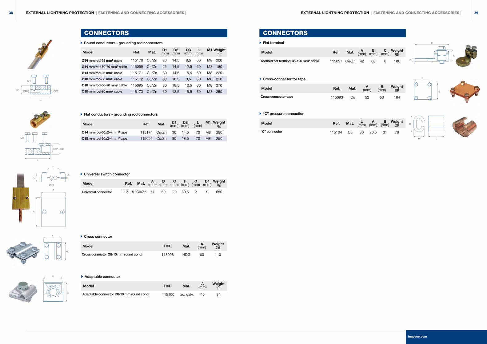
Model
Model
Ø14 mm rod-35 mm² cable
Ø14 mm rod-50-70 mm² cable
Ø14 mm rod-95 mm² cable
Ø18 mm rod-35 mm² cable
Ø18 mm rod-50-70 mm² cable
Ø18 mm rod-95 mm² cable
Ø14 mm rod-30x2-4 mm² tape
Ø18 mm rod-30x2-4 mm² tape
115170 Cu/Zn 25 14,5 8,5 60 M8 200
115055 Cu/Zn 25 14,5 12,5 60 M8 180
115171 Cu/Zn 30 14,5 15,5 60 M8 220
115172 Cu/Zn 30 18,5 8,5 60 M8 290
115095 Cu/Zn 30 18,5 12,5 60 M8 270
115173 Cu/Zn 30 18,5 15,5 60 M8 250
115174 Cu/Zn 30 14,5 70 M8 280
115094 Cu/Zn 30 18,5 70 M8 250
D1 D2 D3 L M1 Weight (mm) (mm) (mm) (mm) (g)
D1 D2 L M1 Weight (mm) (mm) (mm) (g)
Model
Universal connector 112115 Cu/Zn 74 60 20 30,5 2 9 650
A B C F G D1 Weight (mm) (mm) (mm) (mm) (mm) (mm) (g)
CONNECTORS
Model
Model
Toothed flat terminal 35-120 mm² cable
“C” connector
115097 Cu/Zn 42 68 8 186
115104 Cu 30 20,5 31 78
A B C Weight (mm) (mm) (mm) (g)
L A B Weight (mm) (mm) (mm) (g)
CONNECTORS
Round conductors - grounding rod connectors Flat terminal
“C” pressure connection Flat conductors - grounding rod connectors
Universal switch connector
Model
Cross connector Ø8-10 mm round cond. 115098 HDG 60 110
A Weight (mm) (g)
Cross connector
Model
Adaptable connector Ø8-10 mm round cond. 115100 ac. galv. 40 94
A Weight (mm) (g)
Adaptable connector
LA
B
G
ØD1
C
F
B
A
ØD2 ØD1
L
M1
ØD2ØD3ØD1
L
M1
A
A
A
A
C
A
B
Model
Cross connector tape 115093 Cu 52 50 164
A B Weight (mm) (mm) (g)
Cross-connector for tape
B
A
Ref.
Ref.
Ref.
Ref.
Ref.
Ref.
Ref.
Ref.
Mat.
Mat.
Mat.
Mat.
Mat.
Mat.
Mat.
Mat.
EXTERNAL LIGHTNING PROTECTION | FASTENING AND CONNECTING ACCESSORIES | EXTERNAL LIGHTNING PROTECTION | FASTENING AND CONNECTING ACCESSORIES |
ingesco.com
3938
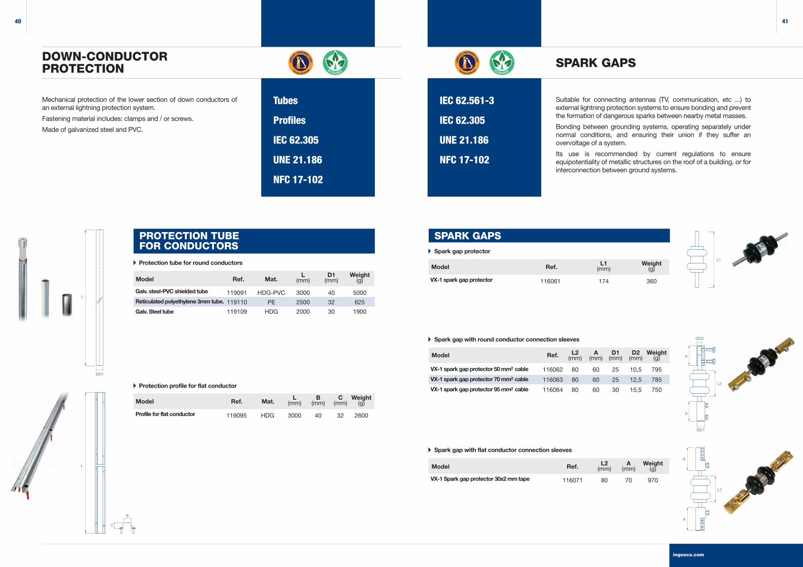
PROTECTION TUBE FOR CONDUCTORS
Tubes
Profiles
IEC 62.305
UNE 21.186
NFC 17-102
Mechanical protection of the lower section of down conductors of an external lightning protection system.
Fastening material includes: clamps and / or screws.
Made of galvanized steel and PVC.
DOWN-CONDUCTORPROTECTION
Galv. steel-PVC shielded tube
Reticulated polyethylene 3mm tube.
Galv. Steel tube
119091 HDG-PVC 3000 40 5000
119110 PE 2500 32 625
119109 HDG 2000 30 1900
L D1 Weight (mm) (mm) (g)
Protection tube for round conductors
Profile for flat conductor 119095 HDG 3000 40 32 2600
L B C Weight (mm) (mm) (mm) (g)
Protection profile for flat conductor
IEC 62.561-3
IEC 62.305
UNE 21.186
NFC 17-102
Suitable for connecting antennas (TV, communication, etc ...) to external lightning protection systems to ensure bonding and prevent the formation of dangerous sparks between nearby metal masses.
Bonding between grounding systems, operating separately under normal conditions, and ensuring their union if they suffer an overvoltage of a system.
Its use is recommended by current regulations to ensure equipotentiality of metallic structures on the roof of a building, or for interconnection between ground systems.
SPARK GAPS
Spark gap with flat conductor connection sleeves
VX-1 Spark gap protector 30x2 mm tape 116071 80 70 970
L2 A Weight (mm) (mm) (g)
Spark gap with round conductor connection sleeves
VX-1 spark gap protector 50 mm2 cable
VX-1 spark gap protector 70 mm2 cable
VX-1 spark gap protector 95 mm2 cable
116062 80 60 25 10,5 795
116063 80 60 25 12,5 785
116064 80 60 30 15,5 750
L2 A D1 D2 Weight (mm) (mm) (mm) (mm) (g)
L
ØD1
L
B
C
Spark gap protector
VX-1 spark gap protector 116061 174 360
L1 Weight (mm) (g)
SPARK GAPS
L1
A
L2
A
A
L2
A
ØD2
Model
Model
Model
Model
Model
Ref.
Ref.
Ref.
Ref.
Ref.
Mat.
Mat.
ØD1
ingesco.com
4140

ISO 9001
Certification
DENA DESARROLLOS SLDuero 5 I 08223 TerrassaBarcelona I SpainT 937 360 305F 937 360 312T (+34) 937 360 [email protected]@ingesco.com
ingesco.com
LEADERS IN LIGHTNING PROTECTION SINCE 1973
PRESENT IN MORE THAN 40 COUNTRIES
PRODUCTS MANUFACTUREDIN SPAIN
DESING OF PREVENTIVE PROTECTION PROJECTS
PRODUCTS NATURAL FIELDTESTED AND CERTIFIED
ON-LINE RISKCALCULATION SOFTWARE
Top Related