


Languages
Pages
Legal


Surgical Technique
EXPERTNailing System
Expert ALFN. Adolescent Lateral Femoral Nail.
This publication is not intended for distribution in the USA.
Instruments and implants approved by the AO Foundation.

Image intensifier control
This description alone does not provide sufficient background for direct use of DePuy Synthes products. Instruction by a surgeon experienced in handling these products is highly recommended.
Processing, Reprocessing, Care and MaintenanceFor general guidelines, function control and dismantling of multi-part instruments, as well as processing guidelines for implants, please contact your local sales representative or refer to:http://emea.depuysynthes.com/hcp/reprocessing-care-maintenanceFor general information about reprocessing, care and maintenance of Synthes reusable devices, instrument trays and cases, as well as processing of Synthes non-sterile implants, please consult the Important Information leaflet (SE_023827) or refer to: http://emea.depuysynthes.com/hcp/reprocessing-care-maintenance

Expert ALFN Surgical Technique DePuy Synthes 1
Table of Contents
Introduction Expert ALFN 2
AO Principles 4
Indications and Contraindications 5
Clinical Cases 6
Surgical Technique Preoperative Planning 10
Opening the Femur 13
Inserting the Nail 18
Locking Options 24
Proximal Locking – Standard 26
Proximal Locking – Recon (Optional) 31
Distal Locking 36
End Cap Insertion 42
Implant Removal 44
Product Information Implants 50
Instruments 54 � Comparison Table 65 � Handling Information 67
Set List 69 � Modular Cases 69 � Vario Cases 73
Optional: Angular Stable Locking System (ASLS) 77
MRI Information 79

2 DePuy Synthes Expert ALFN Surgical Technique
Nail features – Design accommodates a lateral entry site through
the greater trochanter – Anatomic nail design based on a femoral canal study* – Titanium cannulated nail for reamed or unreamed tech-
niques – Lengths from 240 mm to 400 mm, in 20 mm increments – Designed for use in patients where Titanium Elastic Nails
are not large enough and the Expert Lateral Femoral Nail for adults is too large
– 8.2 mm, 9.0 mm, and 10.0 mm diameter nails with 11.0 mm diameter proximal ends
End caps – Prevent ingrowth of tissue and facilitate nail extraction – Self-retaining, T40 Stardrive recess for easy pickup
and insertion of the end cap – Cannulated for insertion over a guide wire – 0 mm end cap sits flush with the nail – 5 mm, 10 mm, and 15 mm end caps extend nail height if
the nail is overinserted
* Ehmke L, Polzin B, Roth C, Bottlang M (2006) Femoral Nailing Through the Trochanter: The Reamer Pathway Indicates A Helical Shape. Journal of Orthopedic Trauma Vol. 20 (Number 10): 668–674
Improved instrumentation – Easy-to-use instrumentation facilitates the surgical
procedure – Ball-tip reaming rod can be removed through the nail and
the insertion instruments, eliminating the need for an exchange tube
– Tailored to the needs of the clinic available as: – an upgrade set for adolescents to Expert Lateral Femoral
System for adults or
– a standard Instrument Set for Expert Adolescent Lateral Femoral Nail
Expert ALFN Adolescent Lateral Femoral Nail System

Expert ALFN Surgical Technique DePuy Synthes 3
Standard locking screws – Double-lead thread for ease of insertion – Thread closer to screw head provides better bone
purchase in the near cortex and improved stability – Titanium alloy* for improved mechanical and fatigue
properties – Self-tapping blunt tip – Self-retaining T25 Stardrive recess allows improved torque
transmission, increased resistance to stripping relative to a hex recess, and secure locking screw pickup
– 4.0 mm diameter
5.0 mm hip screws – Lengths from 50 mm to 125 mm in 5 mm increments – Self-retaining T25 Stardrive recess – Titanium alloy*
* Titanium/6% aluminum/7% niobium alloy

1
4
2
3
4 DePuy Synthes Expert ALFN Surgical Technique
AO Principles
In 1958, the AO formulated four basic principles, which have become the guidelines for internal fixation.1,2
1 Müller ME, M Allgöwer, R Schneider, H Willenegger. Manual of Internal Fixation. 3rd ed. Berlin Heidelberg New York: Springer. 1991
2 Rüedi TP, RE Buckley, CG Moran. AO Principles of Fracture Management. 2nd ed. Stuttgart, New York: Thieme. 2007
Anatomic reductionFracture reduction and fixation to restore anatomical relationships.
Early, active mobilizationEarly and safe mobilization and rehabilitation of the injured part and the patient as a whole.
Stable fixationFracture fixation providing absolute or relative stability, as required by the patient, the injury, and the personality of the fracture.
Preservation of blood supplyPreservation of the blood supply to soft tissues and bone by gentle reduction techniques and careful handling.

Expert ALFN Surgical Technique DePuy Synthes 5
Indications and Contraindications
IndicationsThe Expert Adolescent Lateral Femoral Nail is indicated for use in adolescent and small-stature adult patients to stabilize: – Fractures of the femoral shaft – Subtrochanteric fractures – Ipsilateral neck/shaft fractures – Impending pathologic fractures – Nonunions and malunions
Note: ASLS, the Angular Stable Locking System, is indicated in cases where increased stability is needed in fractures closer to the metaphyseal area or in poor quality bone. For more details regarding the intramedullary fixator principle, please consult the ASLS technique guide (036.000.708) and concept flyer (036.001.017).
ContraindicationsNo specific contraindications.

6 DePuy Synthes Expert ALFN Surgical Technique
Clinical Cases
Case 1 – standard transverse locking – 16-year-old female, 45 kg – Isolated transverse femoral shaft fracture
Case 2 – antegrade locking – 15-year-old male, 55 kg – Oblique midshaft femoral shaft fracture
Preoperative
Preoperative

Expert ALFN Surgical Technique DePuy Synthes 7
Intraoperative
Postoperative
Follow-up (6 weeks after surgery)
Follow-up (4 months after surgery)

8 DePuy Synthes Expert ALFN Surgical Technique
Clinical Cases
Case 3 – recon locking – 12-year-old male, 43 kg – Pathologic proximal femoral shaft fracture
Case 4 – distal locking – 12-year-old male, 30 kg – Oblique distal third femoral shaft fracture
Preoperative
Preoperative

Expert ALFN Surgical Technique DePuy Synthes 9
Postoperative
Postoperative
Follow-up (3 weeks after surgery)
Follow-up (1 month after surgery)
10 DePuy Synthes Expert ALFN Surgical Technique
Preoperative Planning
Use the AO preoperative planner templates for the Expert Adolescent Lateral Femoral Nail (034.000.600/605) to estimate nail length and medullary canal diameter.
To estimate medullary canal diameter, place the template on the AP or lateral x-ray of the femur and measure the dia-meter of the medullary canal at the narrowest part that will contain the nail.
To estimate nail length, place the template on the AP x-ray of the uninjured femur and select the appropriate nail length based on patient anatomy. When selecting nail size, consider canal diameter, fracture pattern, patient anatomy and post-operative protocol.
Note: Templates are available in two sizes: actual size and 115% magnification in which the image is enlarged 15% to correspond to typical radiographic magnification; however, variations in magnification levels are common.
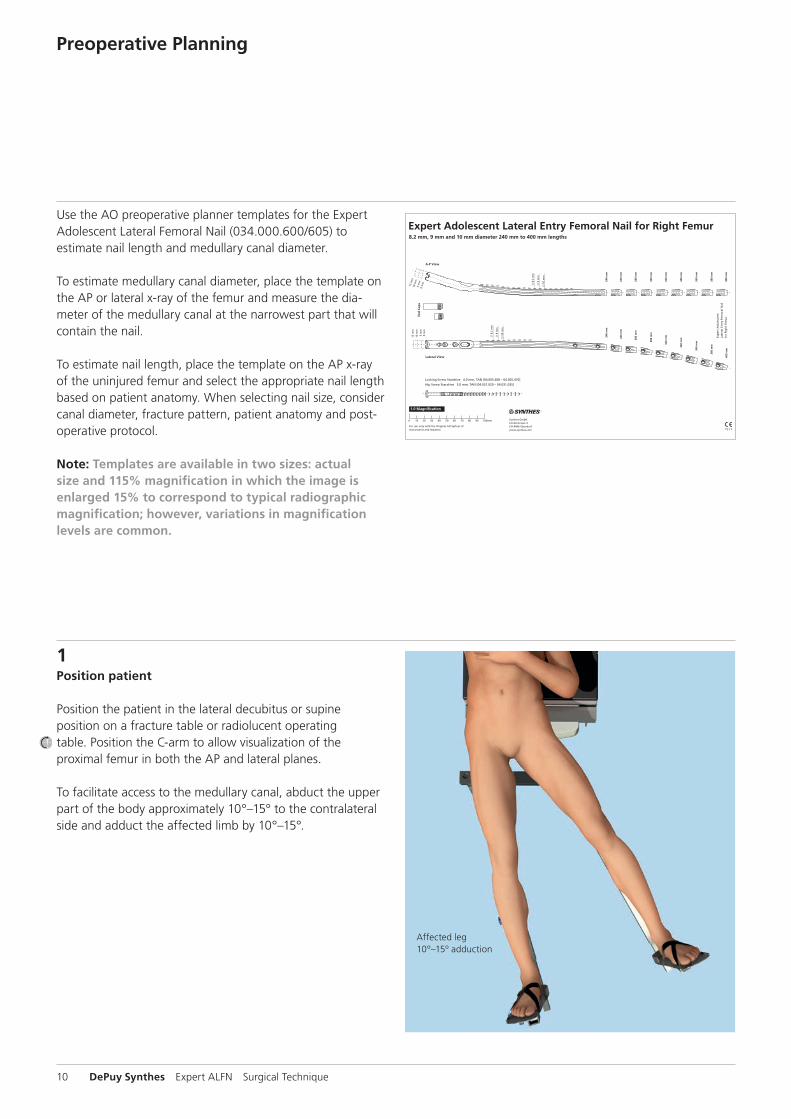
Affected leg10º–15º adduction
Expert Adolescent Lateral Entry Femoral Nail for Right Femur8.2 mm, 9 mm and 10 mm diameter 240 mm to 400 mm lengths
�034
.000
.600
AA
30
1000
64
© 1
2/20
09 S
ynth
es, I
nc.
or
its
affi
liate
s A
ll ri
gh
ts r
eser
ved
Sy
nth
es a
nd
Exp
ert
are
trad
emar
ks o
f Sy
nth
es, I
nc.
or
its
affi
liate
s
0 10 20 30 40 50 60 70 80 90 100mm
For use only with the Original AO System ofInstruments and Implants
Synthes GmbHEimattstrasse 3CH-4436 Oberdorfwww.synthes.com
1.0 Magnification
Locking Screw Stardrive � 4.0 mm, TAN [04.005.408 – 04.005.470]
Hip Screw Stardrive � 5.0 mm, TAN [04.031.020 – 04.031.035]
Ö034.000.600_AAjä
Exp
ert
Ad
ole
scen
tLa
tera
l En
try
Fem
ora
l Nai
lfo
r R
igh
t Fe
mu
r
A-P View
Lateral View
End
Cap
s
15 m
m
240
mm
260
mm
280
mm
300
mm
320
mm
340
mm
360
mm
380
mm
400
mm
240
mm
260
mm
280
mm
300
mm
320
mm
340
mm
360
mm
380
mm
400
mm
10 m
m
5 m
m0
mm
15 m
m10
mm
5 m
m0
mm
9
mm
8
.2 m
m
1
0 m
m
9
mm
8
.2 m
m
1
0 m
m
1Position patient
Position the patient in the lateral decubitus or supine position on a fracture table or radiolucent operating table. Position the C-arm to allow visualization of the proximal femur in both the AP and lateral planes.
To facilitate access to the medullary canal, abduct the upper part of the body approximately 10°–15° to the contralateral side and adduct the affected limb by 10°–15°.

Expert ALFN Surgical Technique DePuy Synthes 11
2Reduce fracture
Perform closed reduction manually by axial traction under image intensifier control. The use of the large distractor may be appropriate in certain circumstances (refer to the surgical technique 036.000.038).
3Confirm nail length
Instrument
03.010.020 Radiographic Ruler for Expert Femoral Nails
The required nail length must be determined after reduction of the femoral fracture.
Position the C-arm for an AP view of the proximal femur. With long forceps, hold the ruler alongside the lateral thigh, parallel to and at the same level as the femur. Adjust the ruler until the proximal end is at the desired nail insertion.

12 DePuy Synthes Expert ALFN Surgical Technique
Preoperative Planning
Move the C-arm to the distal femur. Verify fracture reduction. Align the proximal end of the radiographic ruler to the skin mark, and take an AP image of the distal femur.
Read nail length directly from the ruler image, selecting the measurement proximal to the epiphysis, or at the chosen insertion depth.
Notes: � It is recommended to treat the fracture with the longest nail possible without crossing the physis, taking into account patient anatomy or a previous implant. The distal end of the nail should be 15 mm from the physis.
� Compression (with the conventional backstroke technique) or dynamization must be taken into account when determining the nail length. A shorter nail should be chosen when back hammer ing or dynamization is planned for the procedure (the dynamic slot allows for 7 mm of movement).
4Confirm canal diameter
Instrument
03.010.023 Radiographic Ruler for Nail Diameters for Expert Femoral Nails, length 365 mm
The required nail length must be determined after reduction of the femoral fracture.
Position the C-arm for an AP or lateral view of the femur at the level of the isthmus. Hold the radiographic canal width estimator over the femur with the diameter gauge centered over the narrowest part of the medullary canal. Read the estimated diameter measurement on the circular indicator that fills the canal.
Notes: � If the reamed technique is used, the diameter of the largest medullary reamer must be at least 1.0 mm greater than the nail diameter.
� The ruler provides only an estimate of the canal diameter as it is not at the same level as the femur.

12°
20 mm
Expert ALFN Surgical Technique DePuy Synthes 13
1Approach
Palpate the posterior edge of the greater trochanter.
Make a 3 cm incision in line with the central axis of the intramedullary canal in the lateral view, and depending on the anatomy of the patient, 2–5 cm proximal to the tip of the greater trochanter.
Opening the Femur
2Determine entry point
The insertion point is 12° lateral to the greater trochanter, as measured from a point 20 mm distal to the lesser trochanter.
The entry point can also be described as lateral to the greater trochanter at the same level as the superior aspect of the base of the femoral neck (just above the piriformis fossa). This point can be found by extending a line horizontally from the base of the femoral neck to the lateral side of the femur.
Note: To ensure a correct entry point the preoperative planner template for the ALFN can be used.
14 DePuy Synthes Expert ALFN Surgical Technique
Opening the Femur
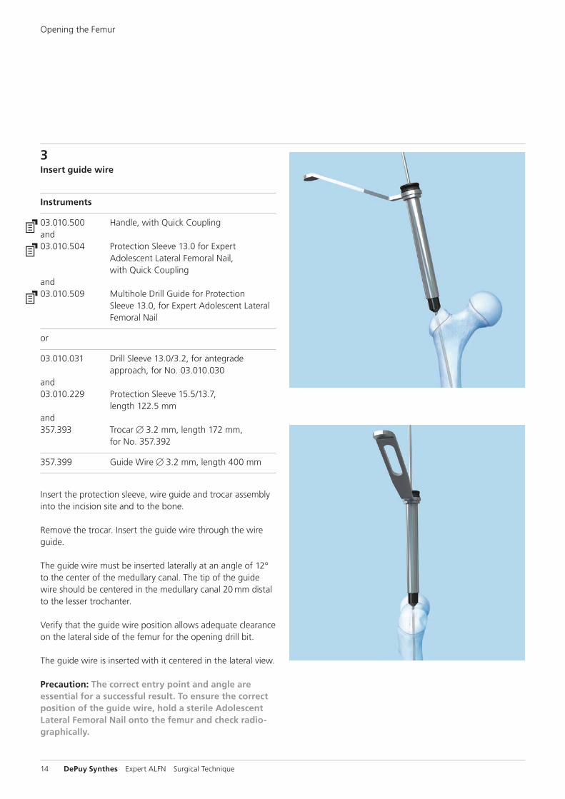
3Insert guide wire
Instruments
03.010.500 Handle, with Quick Couplingand03.010.504 Protection Sleeve 13.0 for Expert
Adolescent Lateral Femoral Nail, with Quick Coupling
and03.010.509 Multihole Drill Guide for Protection
Sleeve 13.0, for Expert Adolescent Lateral Femoral Nail
or
03.010.031 Drill Sleeve 13.0/3.2, for antegrade approach, for No. 03.010.030
and03.010.229 Protection Sleeve 15.5/13.7,
length 122.5 mm and357.393 Trocar B 3.2 mm, length 172 mm,
for No. 357.392
357.399 Guide Wire B 3.2 mm, length 400 mm
Insert the protection sleeve, wire guide and trocar assembly into the incision site and to the bone.
Remove the trocar. Insert the guide wire through the wire guide.
The guide wire must be inserted laterally at an angle of 12° to the center of the medullary canal. The tip of the guide wire should be centered in the medullary canal 20 mm distal to the lesser trochanter.
Verify that the guide wire position allows adequate clearance on the lateral side of the femur for the opening drill bit.
The guide wire is inserted with it centered in the lateral view.
Precaution: The correct entry point and angle are essential for a successful result. To ensure the correct position of the guide wire, hold a sterile Adolescent Lateral Femoral Nail onto the femur and check radiographically.

75 mm
Expert ALFN Surgical Technique DePuy Synthes 15
4Open proximal femur to medullary canal
Instruments
03.010.229 Protection Sleeve 15.5/13.7, length 122.5 mm
or03.010.509 Multihole Drill Guide for Protection
Sleeve 13.0, for Expert Adolescent Lateral Femoral Nail
and03.010.500 Handle, with Quick Coupling
351.270 Drill Bit B 13.0 mm, cannulated, length 290 mm, 3-flute, for Quick Coupling No. 511.760
357.399 Guide Wire B 3.2 mm, length 400 mm
Drill to open cortexDrill through the protection sleeve. Drill the cortex until the drill bit stops in the sleeve.
Remove the guide wire, drill bit and protection sleeve.
Precaution: Dispose of the guide wire. Do not reuse.
Alternative technique to open proximal femurInsert the 2.5 mm reaming rod. Use a reaming system in-tended for femoral reaming procedures to open the proximal femur to a depth of approximately 75 mm, starting with an 8.5 mm reamer and ending with a 13.0 mm reamer.
If reaming the medullary canal, proceed to page 17.

16 DePuy Synthes Expert ALFN Surgical Technique
Opening the Femur
Alternative technique (with awl)
Alternative instruments
03.010.041 Awl B 14.0/3.2 mm, cannulated
357.399 Guide Wire B 3.2 mm, length 400 mm
Place the cannulated awl over the guide wire and open the medullary canal. Use a twisting motion to advance the awl to a depth of approximately 75 mm.
Remove the guide wire and awl.
Precaution: After opening the proximal femur, dispose of the guide wire. Do not reuse.

Expert ALFN Surgical Technique DePuy Synthes 17
5Ream medullary canal (optional)
Instrument
03.010.093 Rod Pusher for Reaming Rod with Hexagonal Screwdriver B 8.0 mm
Note: For the detailed reaming procedure, please consult SynReam Surgical Technique.
If necessary, use a reaming system intended for femur ream-ing procedures to enlarge the medullary femoral canal to the desired diameter.
Check fracture reduction under image intensifier.
Insert reaming rodInsert a 2.5 mm reaming rod into the medullary canal until the desired insertion depth. The tip must be correctly positioned in the medullary canal since it determines the final distal position of the Expert ALFN. The use of the Reduction Instrument for Medullary Nails may be helpful in certain circumstances.
ReamingStarting with the smallest diameter reaming head, ream to a diameter of 0.5 to 1.5 mm greater than the nail dia meter. Ream in 0.5 mm increments and advance the reamer with steady, moderate pressure. Do not force the reamer. Partially retract the reamer repeatedly to clear debris from the medul-lary canal.
Use the holding forceps to retain the reaming rod while reaming and to prevent it from rotating.
18 DePuy Synthes Expert ALFN Surgical Technique
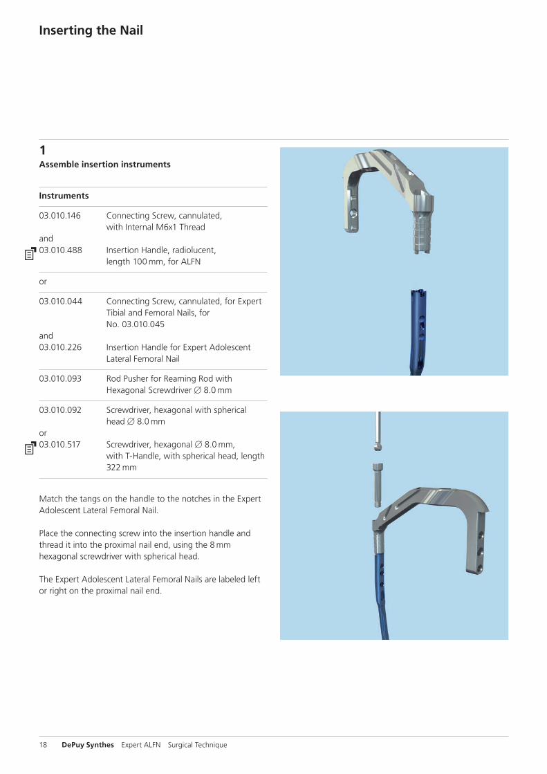
1Assemble insertion instruments
Instruments
03.010.146 Connecting Screw, cannulated, with Internal M6x1 Thread
and03.010.488 Insertion Handle, radiolucent,
length 100 mm, for ALFN
or
03.010.044 Connecting Screw, cannulated, for Expert Tibial and Femoral Nails, for No. 03.010.045
and03.010.226 Insertion Handle for Expert Adolescent
Lateral Femoral Nail
03.010.093 Rod Pusher for Reaming Rod with Hexagonal Screwdriver B 8.0 mm
03.010.092 Screwdriver, hexagonal with spherical head B 8.0 mm
or03.010.517 Screwdriver, hexagonal B 8.0 mm,
with T-Handle, with spherical head, length 322 mm
Match the tangs on the handle to the notches in the Expert Adolescent Lateral Femoral Nail.
Place the connecting screw into the insertion handle and thread it into the proximal nail end, using the 8 mm hexa gonal screwdriver with spherical head.
The Expert Adolescent Lateral Femoral Nails are labeled left or right on the proximal nail end.
Inserting the Nail

Expert ALFN Surgical Technique DePuy Synthes 19
Slide the connecting screw onto the reaming rod push rod. Slide the assembly through the insertion handle and match the tangs on the handle to the nail. Tighten using the hex on the reaming rod push rod.
Secure the assembly using the 8 mm hexagonal screwdriver with spherical head.
Note: The anatomical design of the Adolescents Lateral Femoral Nail requires left and right version nails. The nails are therefore labeled left or right on the proximal anterior end.
Precaution: Check that the connecting screw is correctly tightened. Do not overtighten.

20 DePuy Synthes Expert ALFN Surgical Technique
2Insert nail
Instruments
03.010.523 Driving Cap with thread, for Insertion Handle
and03.010.522 Combined Hammer, 500 gand03.010.170 Hammer Guide
or
03.010.047 Connector, length 141 mm, for Insertion Handle
and03.010.056 Combined Hammer 700 g, can be
mounted, for No. 357.220and357.220 Hammer Guide, for No. 357.250
03.010.092 Screwdriver, hexagonal with spherical head B 8.0 mm
or03.010.517 Screwdriver, hexagonal B 8.0 mm,
with T-Handle, with spherical head, length 322 mm
321.170 Pin Wrench B 4.5 mm, length 120 mm
321.160 Combination Wrench B 11.0 mm
357.398 Shaft, hexagonal, B 8.0 mm, cannulated, short, length 125 mm
Inserting the Nail

Expert ALFN Surgical Technique DePuy Synthes 21
Slide the connector into the groove on the insertion handle and secure it using the 11 mm ratchet wrench. If patient anatomy allows, attach the driving cap in the medial position.
Orient the insertion handle in an anterior position. Use the C-arm to verify fracture reduction. Insert the nail as far as possible.
The nail rotates approximately 90° during insertion. The insertion handle rotates from an anterior to a lateral po-sition during insertion of the last one-third of the nail length. If the nail does not rotate to the lateral position, remove the nail and reinsert it with the handle slightly lateral to the sagittal plane.
Monitor nail passage across the fracture, and control in two planes to avoid malalignment.

22 DePuy Synthes Expert ALFN Surgical Technique
If desired, insert the nail using light hammer blows.
Lock the head of the hammer in place by tightening the nut onto the threads located below the hammer head. Use the pin wrench if necessary. Strike the driving cap directly.
Optionally, the hammer guide can be threaded onto the driving cap and the hammer can be used as a slide hammer. Loosen the nut from the threads located below the hammer head and secure the nut onto the threads located above the handle.
Precautions: � Do not mount the aiming arm until the nail has been completely inserted.
� If nail insertion is difficult, choose a smaller diameter nail or ream the intramedullary canal to a larger diameter.
� Do not hammer directly onto the insertion handle. Retighten and confirm that the nail is securely connected to the insertion handle.
Inserting the Nail

Expert ALFN Surgical Technique DePuy Synthes 23
3Check proximal nail position
Insert the nail until it is at or below the femoral opening.Check final nail position under image intensification in AP and lateral views.
If primary compression or secondary dynamization is planned, it is recommended to overinsert the nail by more than 7 mm, which corresponds to the maximum distance between the positions in static and dynamic modes.
Note: The distance between the markings on the insertion handle is 5 mm and corresponds to the extensions of the end caps. This feature can be used for overinsertion of the nail.
4Check distal nail location
Use image intensification to ensure the nail is centered in both AP and lateral views. Verify fracture alignment.
Remove the reaming rod.

24 DePuy Synthes Expert ALFN Surgical Technique
Locking Options
Proximal locking with recon locking Proximal locking with 120° locking screw
130° CCD
120°

Expert ALFN Surgical Technique DePuy Synthes 25
Proximal locking with dynamization Proximal locking with static transverse locking screw

26 DePuy Synthes Expert ALFN Surgical Technique
1Choose locking option
For standard locking, three targeted proximal locking options are possible:
1 120° antegrade locking2 Dynamic locking (LM)3 Static locking (LM)
For immediate dynamization, insert one proximal locking screw through the dynamic slot. If dynamization may be required in the future, use the dynamic locking option with the 120° antegrade locking hole.
Proximal Locking – Standard
2Mount aiming arm
Instruments
03.010.092 Screwdriver, hexagonal with spherical head B 8.0 mm
or03.010.517 Screwdriver, hexagonal B 8.0 mm,
with T-Handle, with spherical head, length 322 mm
03.010.227 Aiming Arm for Expert Adolescent Lateral Femoral Nail
or03.010.483 Aiming Arm, radiolucent, for
Expert Adolescent Lateral Femoral Nail
Confirm that the nail is securely connected to the insertion handle using the 8 mm ball hex screwdriver. Mount the aiming arm to the insertion handle.

Expert ALFN Surgical Technique DePuy Synthes 27
3Insert trocar assembly
Instruments
03.010.063 Protection Sleeve 12.0/8.0, length 188 mm
03.010.064 Drill Sleeve 8.0/3.2, for No. 03.010.063
03.010.069 Trocar B 3.2 mm, for No. 03.010.064
Insert the three-part trocar assembly (protection sleeve, drill sleeve and trocar) through the desired hole in the aiming arm, make a stab incision and insert the trocar to the bone. Remove the trocar.
If using the 120° antegrade locking option, insert the trocar assembly through the hole labeled “120°” on the insertion handle.
Precaution: Do not exert forces on the aiming arm, protection sleeve, drill sleeves or drill bits. Such force may prevent accurate targeting through the proximal locking holes and damage the drill bits.

28 DePuy Synthes Expert ALFN Surgical Technique
4Drill and determine locking screw length
Instrument
03.010.060* Drill Bit B 3.2 mm, calibrated, length 340 mm, 3-flute, for Quick Coupling, for No. 03.010.064
Ensure that the drill sleeve is pressed firmly to the lateral cortex. Drill through both cortices until the tip of the drill bit just penetrates the far cortex.
Confirm drill bit position.
Ensure that the drill sleeve is pressed firmly to the lateral cortex and read the measurement from the calibrated drill bit at the back of the drill sleeve. This measurement corresponds to the appropriate length locking screw. Remove the drill bit and drill sleeve.
Note: A correct end position of the drill sleeve is important in order to choose the correct length of the locking screw.
* Available nonsterile or sterile-packed. Add "S" to catalog number to order sterile product.
Proximal Locking – Standard
Expert ALFN Surgical Technique DePuy Synthes 29
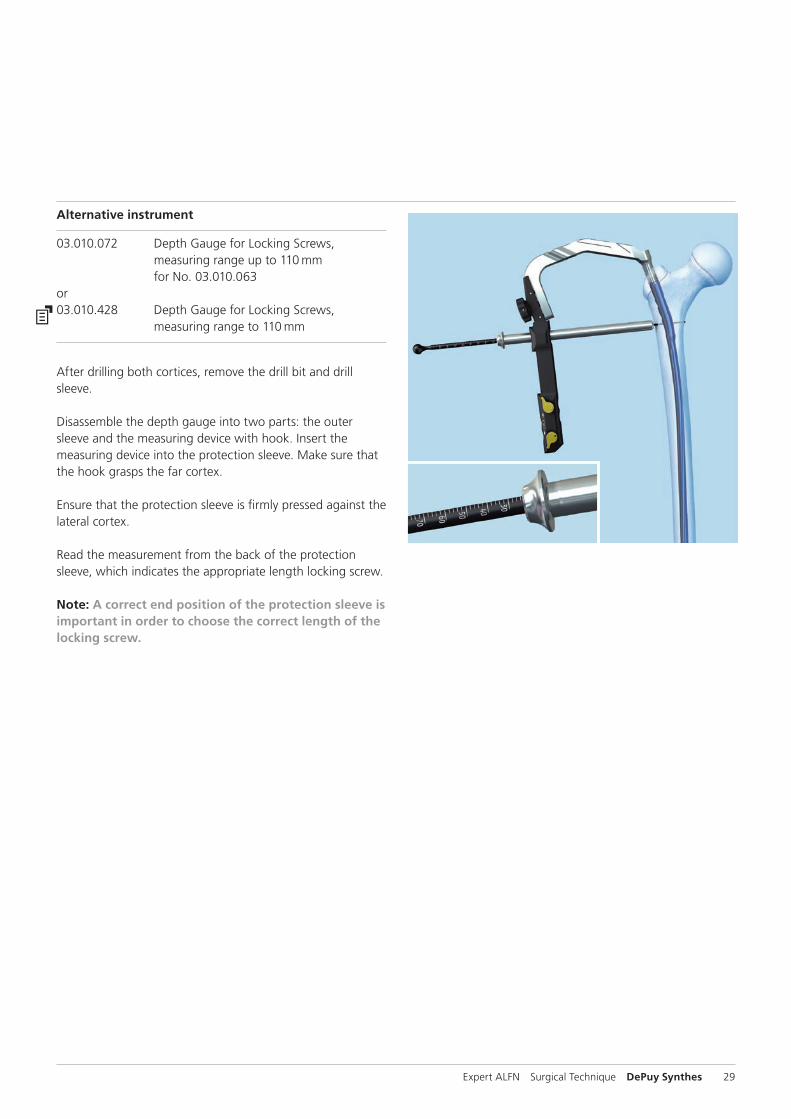
Alternative instrument
03.010.072 Depth Gauge for Locking Screws, measuring range up to 110 mm for No. 03.010.063
or03.010.428 Depth Gauge for Locking Screws,
measuring range to 110 mm
After drilling both cortices, remove the drill bit and drill sleeve.
Disassemble the depth gauge into two parts: the outer sleeve and the measuring device with hook. Insert the measuring device into the protection sleeve. Make sure that the hook grasps the far cortex.
Ensure that the protection sleeve is firmly pressed against the lateral cortex.
Read the measurement from the back of the protection sleeve, which indicates the appropriate length locking screw.
Note: A correct end position of the protection sleeve is important in order to choose the correct length of the locking screw.

30 DePuy Synthes Expert ALFN Surgical Technique
Option: Locking with ASLSASLS, the Angular Stable Locking System, can be used as an alternative to standard locking screws in any round hole of a Synthes cannulated titanium nail. For more details regarding the intramedullary fixator principle please consult the ASLS surgical technique (036.000.708) and concept flyer (036.001.017). Please note that for the use of ASLS special instruments are required.
3Insert locking screw
Instrument
03.010.107 Screwdriver Stardrive, T25, length 330 mmor03.010.518 Screwdriver Stardrive, T25, self-holding, length 319 mm
Insert the appropriate length locking screw through the protection sleeve using the Stardrive screwdriver. Verify locking screw length under image intensification.
The tip of the locking screw should not project more than 2 mm to 4 mm beyond the far cortex.
Note: A groove on the screwdriver provides a rough indication that the locking screw is fully inserted through the sleeve.
Repeat for a second proximal locking screw if desired.
Proximal Locking – Standard

Expert ALFN Surgical Technique DePuy Synthes 31
1Confirm nail position
In the AP view, adjust the nail insertion depth to ensure that the two hip screws can be placed into the femoral head.
Adjust nail position for correct anteversion through the lateral view.
Precaution: Adjusting for the correct anteversion before making a skin incision is crucial to allow uncomplicated guide wire and screw insertion.
2Mount aiming arm
Instruments
03.010.092 Screwdriver, hexagonal with spherical head B 8.0 mm
or03.010.517 Screwdriver, hexagonal B 8.0 mm,
with T-Handle, with spherical head, length 322 mm
03.010.227 Aiming Arm for Expert Adolescent Lateral Femoral Nail
or03.010.483 Aiming Arm, radiolucent, for
Expert Adolescent Lateral Femoral Nail
Confirm that the nail is securely connected to the insertion handle using the screwdriver, hexagonal with spherical head B 8.0 mm. Mount the aiming arm to the insertion handle.
Proximal Locking – Recon (Optional)

32 DePuy Synthes Expert ALFN Surgical Technique
3Insert guide wires for hip screws
Instruments
03.010.075 Protection Sleeve 11.5/8.5, for LFN Reconstruction Locking
03.010.076 Drill Sleeve 8.5/3.2, for No. 03.010.075
03.010.077 Trocar B 3.2 mm, for No. 03.010.076
357.399 Guide Wire B 3.2 mm, length 400 mm
Insert both three-part trocar combinations (protection sleeve, drill sleeve, and trocar) through the aiming arm. Make a stab incision and insert the trocars to the bone.
Following the arrows on the aiming arm, rotate the cams so that the protection sleeves are locked in the aiming arm. This will ensure proper measurement for the hip screws.
Remove the inferior trocar.
Proximal Locking – Recon (Optional)

Expert ALFN Surgical Technique DePuy Synthes 33
In case of an arrested or closed physis, insert a guide wire into the femoral head, stopping approximately 5 mm from the subchondral bone.
If the physis in the femoral head is not fully arrested, stop the wire short of the physis. Check the guide wire placement radiographically in both planes.
Remove the superior trocar and repeat steps for second guide wire.
Precaution: Do not exert force on the aiming arm, protection sleeves, or drill sleeves. Such force may prevent accurate targeting through the locking holes.
34 DePuy Synthes Expert ALFN Surgical Technique
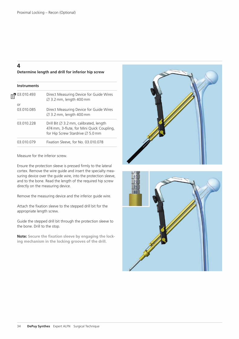
4Determine length and drill for inferior hip screw
Instruments
03.010.493 Direct Measuring Device for Guide Wires B 3.2 mm, length 400 mm
or03.010.085 Direct Measuring Device for Guide Wires
B 3.2 mm, length 400 mm
03.010.228 Drill Bit B 3.2 mm, calibrated, length 474 mm, 3-flute, for Mini Quick Coupling, for Hip Screw Stardrive B 5.0 mm
03.010.079 Fixation Sleeve, for No. 03.010.078
Measure for the inferior screw.
Ensure the protection sleeve is pressed firmly to the lateral cortex. Remove the wire guide and insert the specialty mea-suring device over the guide wire, into the protection sleeve, and to the bone. Read the length of the required hip screw directly on the measuring device.
Remove the measuring device and the inferior guide wire.
Attach the fixation sleeve to the stepped drill bit for the appropriate length screw.
Guide the stepped drill bit through the protection sleeve to the bone. Drill to the stop.
Note: Secure the fixation sleeve by engaging the locking mechanism in the locking grooves of the drill.
Proximal Locking – Recon (Optional)

Expert ALFN Surgical Technique DePuy Synthes 35
5Insert inferior hip screw
Instrument
03.010.108 Screwdriver Stardrive, T25, length 380 mmor03.010.519 Screwdriver Stardrive, T25,
self-holding, length 440 mm
Insert the appropriate hip screw through the protection sleeve into the femoral neck using the long T25 Stardrive screwdriver. Verify the position of the locking screw under image intensification in both planes.
A groove on the screwdriver indicates when the locking screw is fully inserted.
6Insert superior hip screw
Repeat steps 3 through 5 for the superior hip screw.

36 DePuy Synthes Expert ALFN Surgical Technique
1Distal locking
There are two transverse distal locking holes.
2Align image
Check the reduction and correct alignment of the fragments and leg length before locking the nail.
Align the C-arm with the hole in the nail closest to the fracture until a perfect circle is visible in the center of the screen.
3Determine incision point
Place a Kirschner wire on the skin over the center of the hole to mark the incision point and make a stab incision.
Distal Locking

Expert ALFN Surgical Technique DePuy Synthes 37
4Drill
Standard locking with locking screws
Instrument
03.010.103 Drill Bit B 3.2 mm, calibrated, length 145 mm, 3-flute, for Quick Coupling
If using the standard freehand technique, insert the tip of the drill bit through the incision and down to the bone.
Incline the drive so that the tip of the drill bit is centered over the locking hole. Hold the drill bit in this position and drill through both cortices.
Note: For greater drill bit control, discontinue drill power after perforating the near cortex. Manually guide the drill bit through the nail before resuming power to drill the far cortex.

38 DePuy Synthes Expert ALFN Surgical Technique
Alternative instrument
03.010.100 Drill Bit B 3.2 mm, calibrated, length 145 mm, 3-flute, with Coupling for RDL
Using the radiolucent drive under image intensification, insert the tip of the drill bit through the incision and down to the bone.
Incline the drive so that the tip of the drill bit is centered over the locking hole. The drill bit should almost completely fill the circle of the locking hole. Hold the drill bit in this position and drill through both cortices.
Option: Locking with ASLSASLS, the Angular Stable Locking System, can be used as an alternative to standard locking screws in any round hole of a Synthes cannulated titanium nail. For more details regarding the intramedullary fixator prin ciple please consult the ASLS surgical technique (036.000.708) and concept flyer (036.001.017). Please note that for the use of ASLS special instruments are required.
Distal Locking

Expert ALFN Surgical Technique DePuy Synthes 39
5Determine locking screw length
Instruments
03.010.100 Drill Bit B 3.2 mm, calibrated, length 145 mm, 3-flute, with Coupling for RDL
or03.010.103 Drill Bit B 3.2 mm, calibrated,
length 145 mm, 3-flute, for Quick Coupling
03.010.428 Depth Gauge for Locking Screws, measuring range to 110 mm
or03.010.072 Depth Gauge for Locking Screws,
measuring range up to 110 mm, for No. 03.010.063
Stop drilling immediately after penetrating the far cortex. Disassemble the power drive or radiolucent drive from the drill bit.
Ensure the correct position of the drill bit in regard to the far cortex of the femur.
Place the direct measuring device onto the drill bit. Read the graduation on the measuring device at the end of the drill bit. This corresponds to the appropriate locking screw length.
Precaution: Drill bit location with respect to the far cortex is critical for measuring the appropriate locking screw length.

40 DePuy Synthes Expert ALFN Surgical Technique
Alternative instrument
03.010.429 Direct Measuring Device for Drill Bits, length 145 mmor03.010.106 Direct Measuring Device for Drill Bits
of length 145 mm, for Nos. 03.010.100 to 03.010.105
Measure the locking screw length using the depth gauge for locking screws. Ensure the outer sleeve is in contact with the bone and the hook grasps the far cortex.
Distal Locking

Expert ALFN Surgical Technique DePuy Synthes 41
6Insert locking screw
Instruments
03.010.518 Screwdriver Stardrive, T25, self-holding, length 319 mm
or03.010.107 Screwdriver Stardrive, T25,
length 330 mm
03.010.112 Holding Sleeve, with Locking Deviceor03.010.472 Inter-Lock Screwdriver, combined,
Stardrive, T25/hexagonal B 3.5, length 330 mm
Insert the locking screw using the screwdriver, and the holding sleeve with locking device, if desired.
Verify locking screw length under image intensification. The screw tip should be about 2 mm beyond the far cortex. If needed, a second locking screw may be inserted using the same technique.
Use the holding sleeve as described below: Insert the holding sleeve onto the shaft of the screwdriver and place the tip of the screwdriver in the recess of the locking screw (Figure 1).
Push the holding sleeve in the direction of the locking screw. The sleeve now holds the locking screw.
Lock the holding sleeve by tightening it counterclockwise (Figure 2). After insertion of the locking screw, release the holding sleeve by loosening it clockwise and pulling it back (Figure 3).
Read the locking screw length directly from the depth gauge at the back of the outer sleeve.
Note: In the event of a diastasis, the backstroke technique can be used after insertion of the second distal locking screw.
Figure 1
Figure 2
Figure 3

42 DePuy Synthes Expert ALFN Surgical Technique
1Insert end cap
Instruments
03.010.520 Screwdriver Stardrive, T40, with spherical head, cannulated, length 277 mm
or03.010.110 Screwdriver Stardrive, T40, cannulated,
length 300 mm
357.399 Guide Wire B 3.2 mm, length 400 mm
Choose an end cap with the appropriate extension; 0 mm if the nail is not overinserted, 5 mm, 10 mm or 15 mm if the nail is overinserted.
The end caps are cannulated for use over a guide wire, if necessary.
Note: End caps fulfill two functions: they prevent bone ingrowth into the nail; and they extend the nail height if it is overinserted.
Remove the nail insertion instruments.
Optionally, for insertion of the 0 mm end cap, remove the connecting screw only. The insertion handle can r emain to help align the end cap to the top of the nail. The 0 mm end cap fits through the barrel of the insertion handle.
Insert the guide wire into the proximal end of the nail.
Engage the end cap with the cannulated screwdriver by exerting axial pressure. To prevent cross-threading, align the end cap with the nail axis and turn the end cap counter-clockwise, until the thread of the end cap aligns with that of the nail.
Turn the end cap clockwise to thread the end cap into the nail.
Remove the guide wire and screwdriver.
End Cap Insertion

Expert ALFN Surgical Technique DePuy Synthes 43
Alternative instruments
03.010.111 Screwdriver Stardrive, T40, cannulated, length 190 mm, with Lever Arm
321.160 Combination Wrench B 11.0 mm
The cannulated Stardrive, screwdriver, T40, with lever handle, may be used with the 11 mm combination wrench to insert the end cap.

44 DePuy Synthes Expert ALFN Surgical Technique
1Remove end cap and locking screws
Instruments
03.010.518 Screwdriver Stardrive, T25,self-holding, length 319 mm
or03.010.107 Screwdriver Stardrive, T25,
length 330 mm
03.010.520 Screwdriver Stardrive, T40, with spherical head, cannulated, length 277 mm
or03.010.110 Screwdriver Stardrive, T40, cannulated,
length 300 mm
357.399 Guide Wire B 3.2 mm, length 400 mm
Optional instrument
03.010.472 Inter-Lock Screwdriver, combined, Stardrive, T25/hexagonal B 3.5, length 330 mm
or03.010.112 Holding Sleeve, with Locking Device
Implant removal is an optional procedure.
Clear the Stardrive socket of the end cap and the locking im-plants from any tissue ingrowth. Remove the end cap with the screwdriver Stardrive T40. A guide wire can be inserted for easy aligning of the screwdriver into the cannulated end cap.
Implant Removal

Expert ALFN Surgical Technique DePuy Synthes 45
2Attach extraction screw and hammer guide
Instruments
03.010.107 Screwdriver Stardrive, T25, length 330 mm
or03.010.518 Screwdriver Stardrive, T25,self-holding,
length 319 mm
357.133 Extraction Screw for AFN/DFN
357.220 Hammer Guide, for No. 357.250or03.010.170 Hammer Guide
Before removing the final locking screw, screw the extraction screw into the nail and tighten it. The locking screw will prevent nail rotation as the extraction screw is tightened.
Attach the hammer guide to the extraction screw.
Remove the remaining locking screw with the screwdriver. Implant removal is an optional procedure.
3Remove nail
Instrument
03.010.056 Combined Hammer 700 g, can be mounted, for No. 357.220
or03.010.522 Combined Hammer, 500 g
Extract the nail by applying gentle blows with the hammer.
Note: The nail will rotate about 90°, similar to the movement during the insertion.
46 DePuy Synthes Expert ALFN Surgical Technique
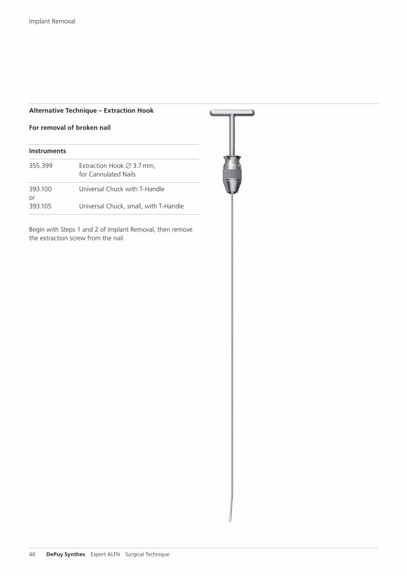
Alternative Technique – Extraction Hook
For removal of broken nail
Instruments
355.399 Extraction Hook B 3.7 mm, for Cannulated Nails
393.100 Universal Chuck with T-Handle or393.105 Universal Chuck, small, with T-Handle
Begin with Steps 1 and 2 of Implant Removal, then remove the extraction screw from the nail.
Implant Removal
Expert ALFN Surgical Technique DePuy Synthes 47
Option 1
1Assemble extraction hook and universal chuck
Insert the extraction hook into the universal chuck with T-handle. The hook should be parallel with the T-handle. This facilitates visualization of the hook position in the bone.
2Insert extraction hook through nail
Pass the extraction hook through the cannula of the nail, including the distant fragment.
Precaution: Under image intensification, verify that the hook has passed through and engaged the distant end of the nail.
3Extract nail
Extract both nail fragments.
Note: Keep the patient’s limb restrained to increase the efficiency of the extraction force.

48 DePuy Synthes Expert ALFN Surgical Technique
Option 2
1Remove near nail fragment
Attach the appropriate extraction bolt or extraction screw to the nail. Remove the near nail fragment using the extraction bolt or extraction screw.
Note: The extraction hook can be used as an alternative to extraction instrumentation.
2Ream canal
Ream the medullary canal 1 mm larger than the nail diameter to clear a path for the distant nail fragment.
3Align extraction hook
Insert the extraction hook and explanted near nail fragment into the medullary canal. The near nail fragment aligns the extraction hook with the cannulation of the distant nail fragment.
Implant Removal

Expert ALFN Surgical Technique DePuy Synthes 49
4Engage distant fragment
Pass the extraction hook through the cannula of the distant nail fragment.
Precaution: Under image intensifi cation, verify that the hook has passed through and engaged the distant end of the nail.
5Extract nail
Extract both nail fragments.
Note: Keep the patient’s limb restrained to increase the effi ciency of the extraction force.

50 DePuy Synthes Expert ALFN Surgical Technique
Expert Adolescent Lateral Femoral Nail – Available for left or right femur – Anatomic nail design based on a femoral canal tracing
study*
Material – Titanium-6% aluminum–7% niobium alloy
Diameters – 8.2 mm, cannulated – 9.0 mm, cannulated – 10.0 mm, cannulated
Lengths – 240 mm through 400 mm in 20 mm increments
Cross Section – Helical fluted
Proximal locking – Dynamization slot (LM) – Static transverse locking hole (LM) – 120° antegrade locking – Two recon locking holes
Distal locking – Two transverse locking holes (LM)
Implants
* L. Ehmke, et al.
50 mm
7 mm
36.25 mm
12.5 mm
20.6 mm120° antegrade
Recon locking
Dynamic transverse
Static transverse
12 mm
LM
42 mm
LM

Expert ALFN Surgical Technique DePuy Synthes 51
Expert Adolescent Lateral Femoral Nail, sterile
Length (mm) B mm Right Left
240 8.2 04.031.924* 04.031.925*
260 8.2 04.031.926* 04.031.927*
280 8.2 04.031.928* 04.031.929*
300 8.2 04.031.930* 04.031.931*
320 8.2 04.031.932* 04.031.933*
340 8.2 04.031.934* 04.031.935*
360 8.2 04.031.936* 04.031.937*
380 8.2 04.031.938* 04.031.939*
400 8.2 04.031.940* 04.031.941*
Length (mm) B mm Right Left
240 9 04.031.944* 04.031.945*
260 9 04.031.946* 04.031.947*
280 9 04.031.948* 04.031.949*
300 9 04.031.950* 04.031.951*
320 9 04.031.952* 04.031.953*
340 9 04.031.954* 04.031.955*
360 9 04.031.956* 04.031.957*
380 9 04.031.958* 04.031.959*
400 9 04.031.960* 04.031.961*
Length (mm) B mm Right Left
240 10 04.031.964* 04.031.965*
260 10 04.031.966* 04.031.967*
280 10 04.031.968* 04.031.969*
300 10 04.031.970* 04.031.971*
320 10 04.031.972* 04.031.973*
340 10 04.031.974* 04.031.975*
360 10 04.031.976* 04.031.977*
380 10 04.031.978* 04.031.979*
400 10 04.031.980* 04.031.981*
* Available non-sterile or sterile packed. Add “S” to the article number to order sterile products.

52 DePuy Synthes Expert ALFN Surgical Technique
Expert End Cap for Adolescent Lateral Femoral Nail B 8.2 mm, Titanium Alloy (TAN), (dark purple)* – Titanium alloy** – Protect nail threads from tissue ingrowth – Cannulated to allow insertion over a guide wire – T40 Stardrive recess
0 mm: Sits flush with end of nail
5 mm, 10 mm and 15 mm extensions: Extend nail height if nail is overinserted
Article No. Extension (mm)
04.031.000 0
04.031.001 5
04.031.002 10
04.031.003 15
Hip Screw Stardrive B 5.0 mm, selftapping, Titanium Alloy (TAN), (dark purple)* – Titanium alloy** – Lengths: 50 mm–125 mm (5 mm increments) – 3.2 mm core diameter – Partially threaded – Self-tapping, blunt tip – T25 Stardrive recess for improved torque transmission
and self-retention on screwdriver
Article No. Length (mm)
04.031.020 50
04.031.021 55
04.031.022 60
04.031.023 65
04.031.024 70
04.031.025 75
04.031.026 80
04.031.027 85
Article No. Length (mm)
04.031.028 90
04.031.029 95
04.031.030 100
04.031.031 105
04.031.032 110
04.031.033 115
04.031.034 120
04.031.035 125
** Available nonsterile or sterile-packed. Add “S” to catalog number to order sterile product.
** Titanium–6% Aluminum–7% Niobium alloy
Implants
Expert ALFN Surgical Technique DePuy Synthes 53
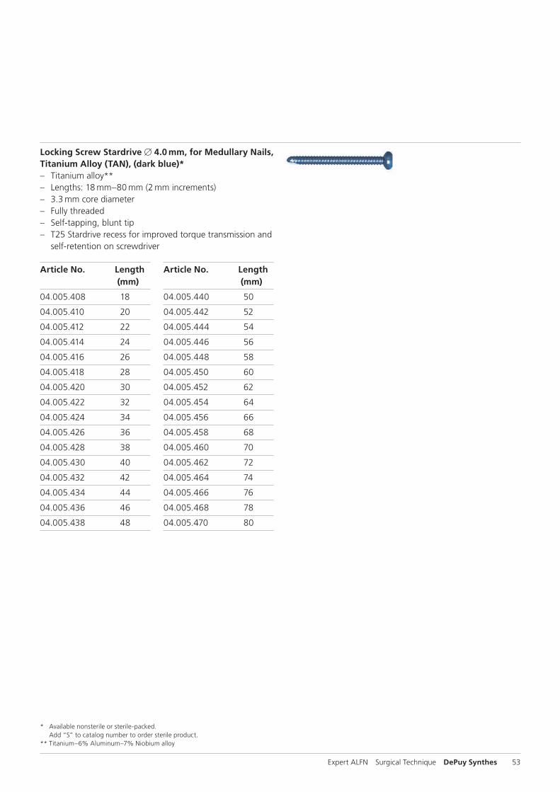
Locking Screw Stardrive B 4.0 mm, for Medullary Nails, Titanium Alloy (TAN), (dark blue)* – Titanium alloy** – Lengths: 18 mm–80 mm (2 mm increments) – 3.3 mm core diameter – Fully threaded – Self-tapping, blunt tip – T25 Stardrive recess for improved torque transmission and
self-retention on screwdriver
Article No. Length (mm)
04.005.408 18
04.005.410 20
04.005.412 22
04.005.414 24
04.005.416 26
04.005.418 28
04.005.420 30
04.005.422 32
04.005.424 34
04.005.426 36
04.005.428 38
04.005.430 40
04.005.432 42
04.005.434 44
04.005.436 46
04.005.438 48
Article No. Length (mm)
04.005.440 50
04.005.442 52
04.005.444 54
04.005.446 56
04.005.448 58
04.005.450 60
04.005.452 62
04.005.454 64
04.005.456 66
04.005.458 68
04.005.460 70
04.005.462 72
04.005.464 74
04.005.466 76
04.005.468 78
04.005.470 80
* Available nonsterile or sterile-packed. Add “S” to catalog number to order sterile product.
** Titanium–6% Aluminum–7% Niobium alloy

54 DePuy Synthes Expert ALFN Surgical Technique
Standard instrumentation
321.160 Combination Wrench B 11.0 mm
357.398 Shaft, hexagonal, B 8.0 mm, cannulated, short, length 125 mm
357.399 Guide Wire B 3.2 mm, length 400 mm
393.100 Universal Chuck with T-Handle
321.170 Pin Wrench B 4.5 mm, length 120 mm
351.270 Drill Bit B 13.0 mm, cannulated, length 290 mm, 3-flute, for Quick Coupling No. 511.760
Instruments

Expert ALFN Surgical Technique DePuy Synthes 55
03.010.060* Drill Bit B 3.2 mm, calibrated, length 340 mm, 3-flute, for Quick Coupling, for No. 03.010.064
* Available nonsterile or sterile-packed. Add “S” to catalog number to order sterile product.
03.010.000 Extraction Screw, for Tibial and Femoral Nails
03.010.023 Radiographic Ruler for Nail Diameters for Expert Femoral Nails, length 365 mm
03.010.063 Protection Sleeve 12.0/8.0, length 188 mm
03.010.064 Drill Sleeve 8.0/3.2, for No. 03.010.063
03.010.069 Trocar B 3.2 mm, for No. 03.010.064
03.010.020 Radiographic Ruler for Expert Femoral Nails

56 DePuy Synthes Expert ALFN Surgical Technique
03.010.500 Handle, with Quick Coupling
03.010.170 Hammer Guide
03.010.497 Cam-Lock Lever for Aiming Arm
03.010.146 Connecting Screw, cannulated,with Internal M6x1 Thread
03.010.483 Aiming Arm, radiolucent, for Expert Adolescent Lateral Femoral Nail
03.010.488 Insertion Handle, radiolucent, length 100 mm, for Expert ALFN
03.010.428 Depth Gauge for Locking Screws, measuring range up to 110 mm
Instruments
Expert ALFN Surgical Technique DePuy Synthes 57
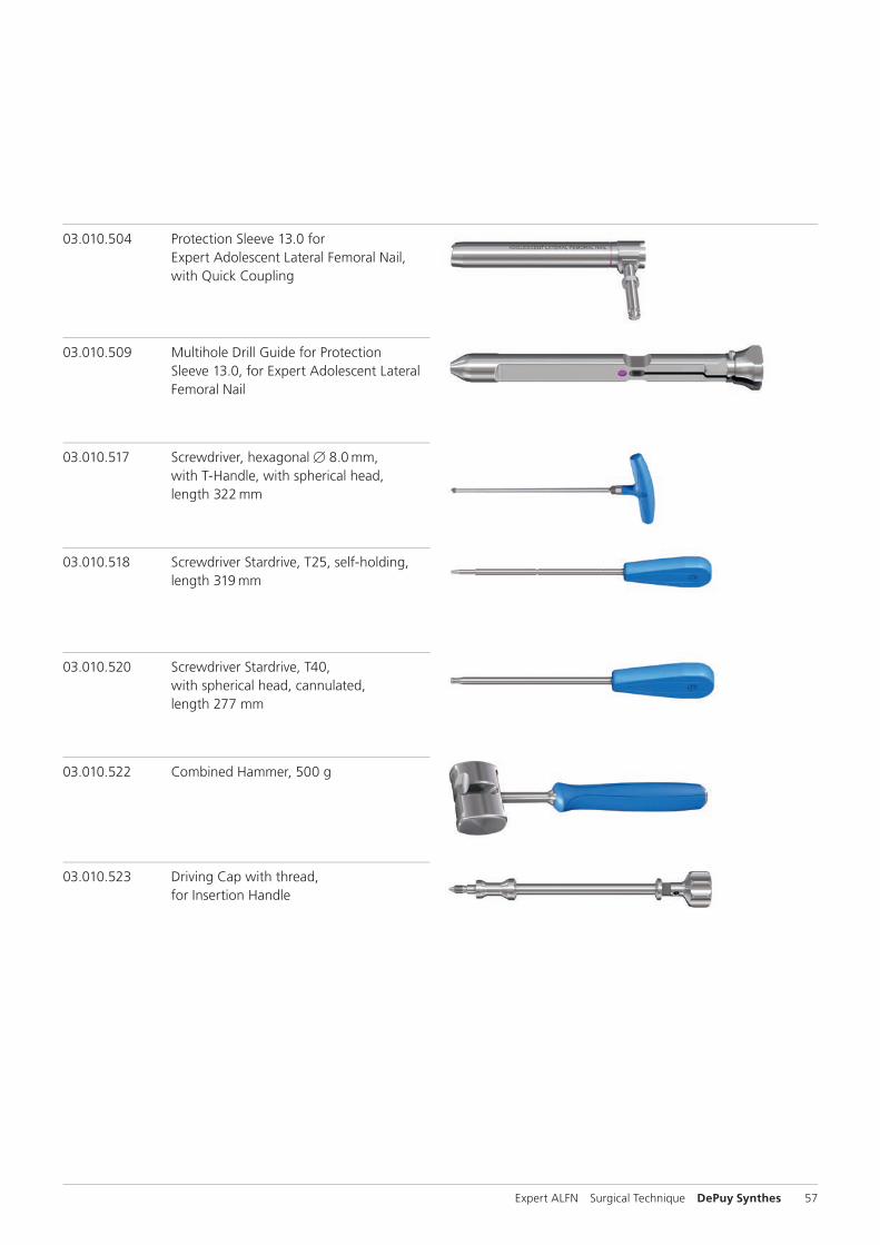
03.010.504 Protection Sleeve 13.0 for Expert Adolescent Lateral Femoral Nail, with Quick Coupling
03.010.509 Multihole Drill Guide for Protection Sleeve 13.0, for Expert Adolescent Lateral Femoral Nail
03.010.517 Screwdriver, hexagonal B 8.0 mm, with T-Handle, with spherical head, length 322 mm
03.010.518 Screwdriver Stardrive, T25, self-holding, length 319 mm
03.010.520 Screwdriver Stardrive, T40, with spherical head, cannulated, length 277 mm
03.010.523 Driving Cap with thread, for Insertion Handle
03.010.522 Combined Hammer, 500 g

58 DePuy Synthes Expert ALFN Surgical Technique
03.010.041 Awl B 14.0/3.2 mm, cannulated
355.399 Extraction Hook B 3.7 mm, for Cannulated Nails
Optional instruments
351.050 Tissue Protector
03.010.019 Depth Gauge for Locking Screws, measuring range up to 110 mm, for No. 03.010.009
03.010.075 Protection Sleeve 11.5/8.5, for LFN Reconstruction Locking
03.010.076 Drill Sleeve 8.5/3.2, for No. 03.010.075
03.010.077 Trocar B 3.2 mm, for No. 03.010.076
Instruments

Expert ALFN Surgical Technique DePuy Synthes 59
03.010.079 Fixation Sleeve, for No. 03.010.078
03.010.093 Rod Pusher for Reaming Rod with Hexagonal Screwdriver B 8.0 mm
03.010.100 Drill Bit B 3.2 mm, calibrated, length 145 mm, 3-flute, with Coupling for RDL
03.010.103 Drill Bit B 3.2 mm, calibrated, length 145 mm, 3-flute, for Quick Coupling
03.010.111 Screwdriver Stardrive, T40, cannulated, length 190 mm, with Lever Arm
03.010.228 Drill Bit B 3.2 mm, calibrated, length 474 mm, 3-flute, for Mini Quick Coupling, for Hip Screw Stardrive B 5.0 mm

60 DePuy Synthes Expert ALFN Surgical Technique
03.010.429 Direct Measuring Device for Drill Bits, length 145 mm
03.010.473 Inter-Lock Screwdriver, combined, Stardrive, T25/hexagonal B 3.5, length 224 mm
03.010.491 Handle for Scalpel, long
03.010.493 Direct Measuring Device for Guide Wires B 3.2 mm, length 400 mm
03.010.472 Inter-Lock Screwdriver, combined, Stardrive, T25/hexagonal B 3.5, length 330 mm
Instruments

Expert ALFN Surgical Technique DePuy Synthes 61
03.010.513 Screwdriver Stardrive, T25, self-holding, length 250 mm
03.010.515 Inter-Lock Screwdriver Stardrive, T40, length 377 mm
03.010.495 Intramedullary Reduction Tool, curved, with Quick Coupling, Hex 12 mm
03.010.496 T-Handle, cannulated, with Quick Coupling, Hex 12 mm
03.010.519 Screwdriver Stardrive, T25, self-holding, length 440 mm

62 DePuy Synthes Expert ALFN Surgical Technique
Alternative instruments
393.105 Universal Chuck, small, with T-Handle
03.010.044 Connecting Screw, cannulated, for Expert Tibial and Femoral Nails, for No. 03.010.045
03.010.047 Connector, length 141 mm, for Insertion Handle
03.010.056 Combined Hammer 700 g, can be mounted, for No. 357.220
357.133 Extraction Screw for AFN/DFN
357.220 Hammer Guide, for No. 357.250
357.393 Trocar B 3.2 mm, length 172 mm, for No. 357.392
03.010.031 Drill Sleeve 13.0/3.2 for antegrade approach, for No. 03.010.030
Instruments

Expert ALFN Surgical Technique DePuy Synthes 63
03.010.072 Depth Gauge for Locking Screws, measuring range up to 110 mm, for No. 03.010.063
03.010.085 Direct Measuring Device for Guide Wires B 3.2 mm, length 400 mm
03.010.092 Screwdriver, hexagonal with spherical head B 8.0 mm
03.010.106 Direct Measuring Device for Drill Bits of length 145 mm, for Nos. 03.010.100 to 03.010.105
03.010.107 Screwdriver Stardrive, T25, length 330 mm
03.010.108 Screwdriver Stardrive, T25, length 380 mm
03.010.110 Screwdriver Stardrive, T40, cannulated, length 300 mm
64 DePuy Synthes Expert ALFN Surgical Technique
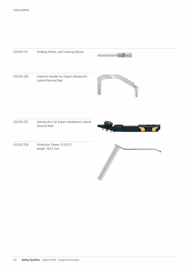
03.010.226 Insertion Handle for Expert Adolescent Lateral Femoral Nail
03.010.229 Protection Sleeve 15.5/13.7, length 122.5 mm
03.010.227 Aiming Arm for Expert Adolescent Lateral Femoral Nail
03.010.112 Holding Sleeve, with Locking Device
Instruments

� � ��� � � ��� � �
Expert ALFN Surgical Technique DePuy Synthes 65
Standard Article Alternative Article
� 03.010.504� 03.010.509� 03.010.500
� 03.010.229� 03.010.031� 357.393
InstrumentsComparison Table
Standard Article Alternative Article
� 03.010.488� 03.010.146� 03.010.523
� 03.010.226� 03.010.146� 03.010.047
Standard Article Alternative Article
03.010.483 03.010.227

��
66 DePuy Synthes Expert ALFN Surgical Technique
Standard Article Alternative Article
03.010.493 03.010.085
03.010.517 03.010.092
03.010.518 03.010.107
Standard Article Alternative Article
03.010.429 03.010.106
03.010.170 357.220
03.010.472 � 03.010.107� 03.010.112
03.010.428 03.010.072
Standard Article Alternative Article
03.010.519 03.010.108
03.010.520 03.010.110
03.010.522 03.010.056
InstrumentsComparison Table

Expert ALFN Surgical Technique DePuy Synthes 67
InstrumentsHandling Information
Aiming Arm (03.010.483)
– Easy snap-on and snap-off mechanism – “Friction” and “True locking” – Backward compatible with existing devices – Radiolucent – More soft tissue clearance – Easy disassembly for cleaning
1. Some force is required to push the cam lock mechanism over the wings.
2. To fi x the cam lock mechanism at the corresponding pins, the cam lock must be pushed back in open position.
Scalpel Handle (03.010.491)
– For channel cutting to minimize muscle force on the protection sleeves
– Yellow Silicon handle indicates sharpness of instrument
1. Attach a blade to the scalpel holding the end of the handle.
Insertion Handle (03.010.488)
– Radiolucent – Attachment for driving cap with threaded end
(03.010.523)
InterLock ScrewdriverCompatible with all Synthes T25 or 3.5 mm hexagonal re-cess. For further information, please refer to brochure 036.001.581.
– Tear drop shape – Silicon handle
Precaution: When removing implants after longterm implantation, especially in the presence of large amounts of bony ingrowth, fi rst use a solid screw-driver to loosen the screw. The interlock screwdriver
can then be used to remove the screw from the surgical site. If using the interlock screwdriver with locking screws, use a solid screwdriver for fi nal tightening.
2. Pass the scalpel handle through the aiming arm holes and perform a minimally invasive and accurate incision.
3. Remove the scalpel from the aiming arm.
1 2
68 DePuy Synthes Expert ALFN Surgical Technique
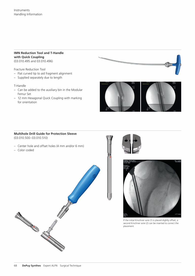
IMN Reduction Tool and THandle with Quick Coupling (03.010.495 and 03.010.496)
Fracture Reduction Tool – Flat curved tip to aid fragment alignment – Supplied separately due to length
T-Handle – Can be added to the auxiliary bin in the Modular
Femur Set – 12 mm Hexagonal Quick Coupling with marking
for orientation
Multihole Drill Guide for Protection Sleeve (03.010.500–03.010.510)
– Center hole and offset holes (4 mm and/or 6 mm) – Color coded
If the initial Kirschner wire (1) is placed slightly offset, a second Kirschner wire (2) can be inserted to correct the placement.
InstrumentsHandling Information

Expert ALFN Surgical Technique DePuy Synthes 69
Set ListModular Cases
The modularity of the system enables sets to be confi gured according to the hospital’s clinical needs. Each set confi gu-ration consists of basic instruments, dedicated system instru-ments and optional instruments (if required). For femoral nails (LFN, ALFN, R/AFN) the femur set must be added to the set confi guration. New modular trays also contain the ASLS instruments. For further information about ASLS refer to pages 77 and 78.
The instrument modules listed on the right side are available.
For ease of use within the operating theatre, all modular trays have an additional marking: – Mandatory modular trays have a solid white marking – Optional trays have a hatched black marking – Each system has a control picture for reference
ETN R/AFN LFN ALFN
01.010.412 Instruments for ETN
01.010.413 Instruments for R/AFN
01.010.414 Instruments for LFN
01.010.415 Instruments for ALFN
ETN Aiming Arm (separate)
01.010.411Instruments for Expert Femoral Nail
01.010.410Basic Instruments for Expert Nail
01.010.416Additional Instruments for Expert Nail (Optional)

FEMUR
BASIC
ALFN
ALFN BASIC FEMUR
OPT
OPT
70 DePuy Synthes Expert ALFN Surgical Technique
Modular ALFN Set 01.010.413Control Picture
ALFN Instruments Tray
Basic Instruments Tray
Femur Instruments Tray
Optional Instruments Tray
Set ListModular Cases
Expert ALFN Surgical Technique DePuy Synthes 71
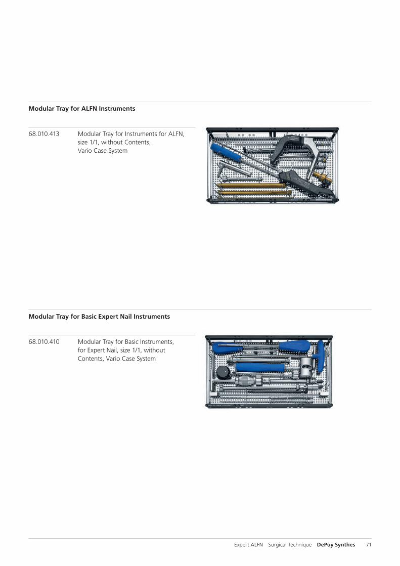
Modular Tray for ALFN Instruments
68.010.413 Modular Tray for Instruments for ALFN, size 1/1, without Contents, Vario Case System
Modular Tray for Basic Expert Nail Instruments
68.010.410 Modular Tray for Basic Instruments, for Expert Nail, size 1/1, without Contents, Vario Case System
72 DePuy Synthes Expert ALFN Surgical Technique
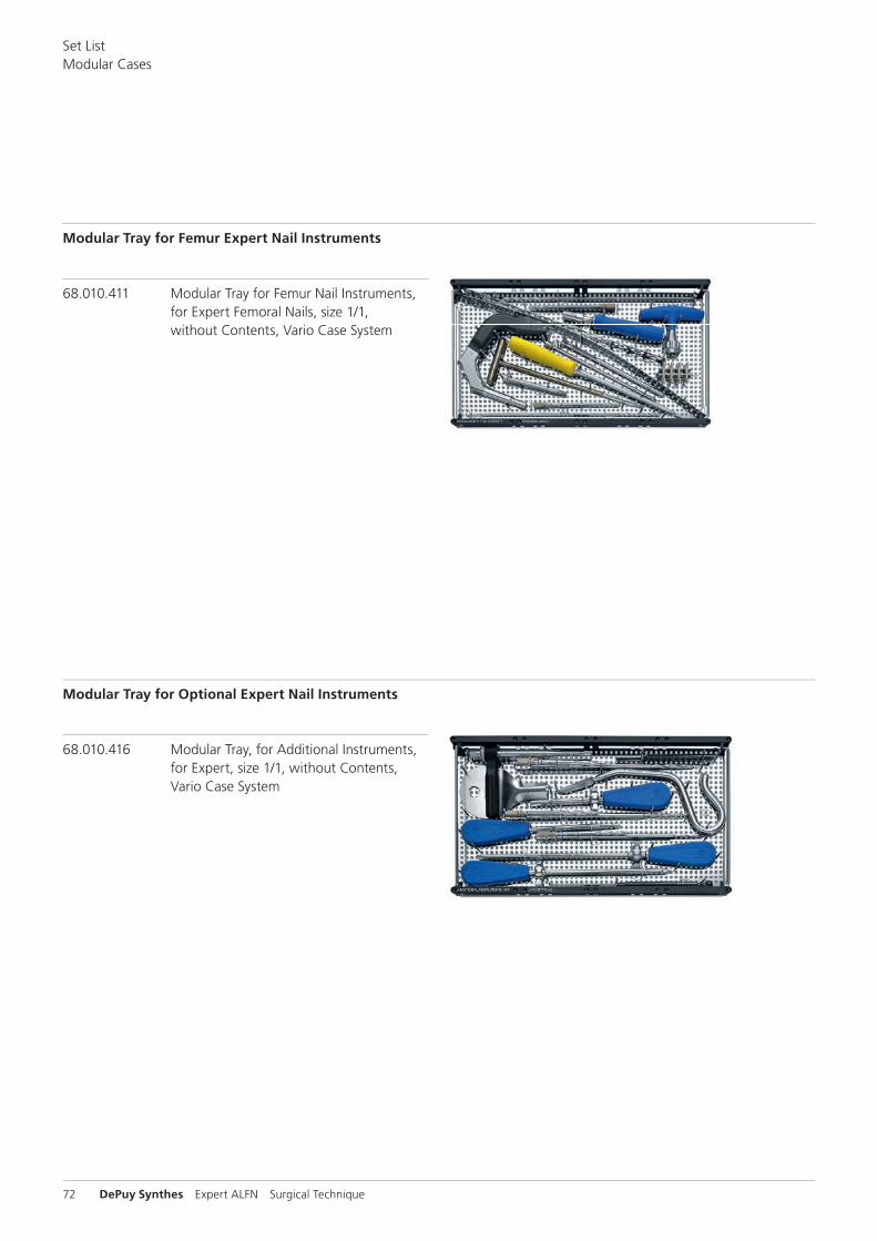
Modular Tray for Femur Expert Nail Instruments
68.010.411 Modular Tray for Femur Nail Instruments, for Expert Femoral Nails, size 1/1, without Contents, Vario Case System
Modular Tray for Optional Expert Nail Instruments
68.010.416 Modular Tray, for Additional Instruments, for Expert, size 1/1, without Contents, Vario Case System
Set ListModular Cases

Expert ALFN Surgical Technique DePuy Synthes 73
Set List
Vario Cases
* Available nonsterile or sterile-packed. Add “S” to catalog number to order sterile product. Note: For additional information, please refer to package insert.
01.031.004 Expert Adolescent Lateral Femoral Nail Instrument Set in Vario Case
68.031.004 Vario Case for Standard Instrument Set, for Expert Ado-lescent Lateral Femoral Nail, without Lid, without Contents
351.270 Drill Bit B 13.0 mm, cannulated, length 290 mm, 3-flute, for Quick Coupling No. 511.760
1
321.160 Combination Wrench B 11.0 mm 1
321.170 Pin Wrench B 4.5 mm, length 120 mm 1
357.133 Extraction Screw for AFN/DFN 1
357.220 Hammer Guide, for No. 357.250 1
357.393 Trocar B 3.2 mm, length 172 mm, for No. 357.392 1
357.399 Guide Wire B 3.2 mm, length 400 mm 10
393.105 Universal Chuck, small, with T-Handle 1
03.010.020 Radiographic Ruler for Expert Femoral Nails 1
03.010.023 Radiographic Ruler for Nail Diameters for Expert Femoral Nails, length 365 mm
1
03.010.031 Drill Sleeve 13.0/3.2, for antegrade approach, for No. 03.010.030
1
03.010.044 Connecting Screw, cannulated, for Expert Tibial and Femoral Nails, for No. 03.010.045
2
03.010.047 Connector, length 141 mm, for Insertion Handle 1
03.010.056 Combined Hammer 700 g, can be mounted, for No. 357.220
1
03.010.060* Drill Bit B 3.2 mm, calibrated, length 340 mm, 3-flute, for Quick Coupling, for No. 03.010.064
2
03.010.063 Protection Sleeve 12.0/8.0, lenght 188 mm 1
03.010.064 Drill Sleeve 8.0/3.2, for No. 03.010.063 1
03.010.069 Trocar B 3.2 mm, for No. 03.010.064 1
03.010.072 Depth Gauge for Locking Screws, measuring range up to 110 mm, for No. 03.010.063
1
03.010.075 Protection Sleeve 11.5/8.5, for LFN Reconstruction Locking 2
03.010.076 Drill Sleeve 8.5/3.2, for No. 03.010.075 2
03.010.077 Trocar B 3.2 mm, for No. 03.010.076 2
03.010.079 Fixation Sleeve, for No. 03.010.078 1
03.010.085 Direct Measuring Device for Guide Wires B 3.2 mm, length 400 mm
1
03.010.092 Screwdriver, hexagonal with spherical head B 8.0 mm
1
03.010.093 Rod Pusher for Reaming Rod with Hexagonal Screwdriver B 8.0 mm
1
03.010.100 Drill Bit B 3.2 mm, calibrated, length 145 mm, 3-flute, with Coupling for RDL
1
03.010.103* Drill Bit B 3.2 mm, calibrated, length 145 mm, 3-flute, for Quick Coupling
1
03.010.106 Direct Measuring Device for Drill Bits of length 145 mm for Nos. 03.010.100 to 03.010.105
1
03.010.107 Screwdriver Stardrive, T25, length 330 mm 1
03.010.108 Screwdriver Stardrive, T25, length 380 mm 1
03.010.110 Screwdriver Stardrive, T40, cannulated, length 300 mm 1
03.010.111 Screwdriver Stardrive, T40, cannulated, length 190 mm, with Lever Arm
1
03.010.112 Holding Sleeve, with Locking Device 1
03.010.226 Insertion Handle for Expert Adolescent Lateral Femoral Nail 1
03.010.227 Aiming Arm for Expert Adolescent Lateral Femoral Nail 1
03.010.228 Drill Bit B 3.2 mm, calibrated, length 474 mm, 3-flute, for Mini Quick Coupling, for Hip Screw Stardrive B 5.0 mm
1
03.010.229 Protection Sleeve 15.5/13.7, length 122.5 mm 1

74 DePuy Synthes Expert ALFN Surgical Technique
* Available nonsterile or sterile-packed. Add “S” to catalog number to order sterile product. Note: For additional information, please refer to package insert.
01.031.005 Expert Adolescent Lateral Femoral Nail Upgrade for LFN Instrument Set in Vario Case
68.031.005 Vario Case for Upgrade Instrument Set, for Expert Ado-lescent Lateral Femoral Nail, without Lid, without Contents
1
351.270 Drill Bit B 13.0 mm, cannulated, length 290 mm, 3-flute,
for Quick Coupling No. 511.760
1
357.133 Extraction Screw for AFN/DFN 1
357.393 Trocar B 3.2 mm, length 172 mm, for No. 357.392 1
03.010.031 Drill Sleeve 13.0/3.2 for antegrade approach, for No. 03.010.030
1
03.010.060* Drill Bit B 3.2 mm, calibrated, length 340 mm, 3-flute, for Quick Coupling, for No. 03.010.064
2
03.010.063 Protection Sleeve 12.0/8.0, length 188 mm 1
03.010.064 Drill Sleeve 8.0/3.2, for No. 03.010.063 1
03.010.069 Trocar B 3.2 mm, for No. 03.010.064 1
03.010.093 Rod Pusher for Reaming Rod with Hexagonal Screwdriver B 8.0 mm
1
03.010.100 Drill Bit B 3.2 mm, calibrated, length 145 mm, 3-flute, with Coupling for RDL
2
03.010.103 Drill Bit B 3.2 mm, calibrated, length 145 mm, 3-flute,for Quick Coupling
1
03.010.111 Screwdriver Stardrive, T40, cannulated, length 190 mm, with Lever Arm
1
03.010.226 Insertion Handle for Expert Adolescent Lateral Femoral Nail 1
03.010.227 Aiming Arm for Expert Adolescent Lateral Femoral Nail 1
03.010.228 Drill Bit B 3.2 mm, calibrated, length 474 mm, 3-flute, for Mini Quick Coupling, for Hip Screw Stardrive B 5.0 mm
1
03.010.229 Protection Sleeve 15.5/13.7, length 122.5 mm 1
01.031.004 Expert Adolescent Lateral Femoral Nail Instrument Set in Vario Case
01.031.005 Expert Adolescent Lateral Femoral Nail Upgrade for LFN Instrument Set in Vario Case
Set ListVario Cases

Expert ALFN Surgical Technique DePuy Synthes 75
Option: Modular Aiming Device ModAD
Option for Carm independent distal locking of nails for femur, tibia and humerus
When using the ModAD for the interlocking of intra-medullary nails, no image intensifier control is required. The system is especially suitable when no C-arm is available.
01.010.309 ModAD for Expert LFN and HN
68.010.035 Sliding Carriage for Expert Tibial Nails, for Calibration Block No. 312.952
The ModAD for Expert LFN has to be used with the Sliding Carriage for Expert Tibial Nails. Distal locking is performed using the sliding carriage.

76 DePuy Synthes Expert ALFN Surgical Technique
01.031.003 Implant Set for Expert Adolescent Lateral Femoral Nail
68.031.002 Screw Rack, 1/4, for Locking Screw Stardrive B 4.0 mm and Hip Screw Stardrive B 5.0 mm, with Module, with Lid
Instrument
319.970 Screw Forceps, self-holding, length 85 mm
Implants
Locking Screw Stardrive B 4.0 mm, for Medullary Nails, Titanium Alloy (TAN), dark blue, 2 each*
Article No. Length (mm) Article No. Length (mm)
04.005.416 26 04.005.444 54
04.005.418 28 04.005.446 56
04.005.420 30 04.005.448 58
04.005.422 32 04.005.450 60
04.005.424 34 04.005.452 62
04.005.426 36 04.005.454 64
04.005.428 38 04.005.456 66
04.005.430 40 04.005.458 68
04.005.432 42 04.005.460 70
04.005.434 44 04.005.462 72
04.005.436 46 04.005.464 74
04.005.438 48 04.005.466 76
04.005.440 50 04.005.468 78
04.005.442 52 04.005.470 80
Hip Screw Stardrive B 5.0 mm, selftapping, for Expert ALFN, Titanium Alloy (TAN), dark purple, 4 each
5.0 mm Titanium Recon Screws*, with T25 StarDrive recess, for IM Nails, 4 each.
Article No. Length (mm) Article No. Length (mm)
04.031.022 60 04.031.029 95
04.031.023 65 04.031.030 100
04.031.024 70 04.031.031 105
04.031.025 75 04.031.032 110
04.031.026 80 04.031.033 115
04.031.027 85 04.031.034 120
04.031.028 90
Expert End Cap, for Expert ALFN B 8.2 mm, Titanium Alloy (TAN), dark purple*
Article No. Extension (mm)
04.031.000 0 2 each
04.031.001 5 1
04.031.002 10 1
04.031.003 15 1 * Available nonsterile or sterile-packed. Add “S” to catalog number to order sterile product. Note: For additional information, please refer to package insert.
Optionally available
Hip Screws*
04.031.020 Hip Screw Stardrive B 5.0 mm, self-tapping, length 50 mm, for Expert ALFN, Titanium Alloy (TAN), dark purple
04.031.021 Hip Screw Stardrive B 5.0 mm, self-tapping, length 55 mm, for Expert ALFN, Titanium Alloy (TAN), dark purple
04.031.035 Hip Screw Stardrive B 5.0 mm, self-tapping, length 125 mm, for Expert ALFN, Titanium Alloy (TAN), dark purple
Locking Screws
04.005.408 Locking Screw Stardrive B 4.0 mm, length 18 mm, for Medullary Nails, Titanium Alloy (TAN), blue
04.005.410 Locking Screw Stardrive B 4.0 mm, length 20 mm, for Medullary Nails, Titanium Alloy (TAN), blue
04.005.412 Locking Screw Stardrive B 4.0 mm, length 22 mm, for Medullary Nails, Titanium Alloy (TAN), blue
04.005.414 Locking Screw Stardrive B 4.0 mm, length 24 mm, for Medullary Nails, Titanium Alloy (TAN), blue
Set ListVario Cases

Expert ALFN Surgical Technique DePuy Synthes 77
What is ASLS?The Angular Stable Locking System (ASLS) provides the abil-ity to create a fixed-angle construct to an intrame dullary nail. Therefore, it combines the advantages of angular stability and a minimally invasive approach. ASLS together with an intramedullary nail form the principle of the Intramedullary Fixator.
Optional: Angular Stable Locking System (ASLS)
The following description contains general information about ASLS. For further details on the application and compatibility of ASLS please refer to the Surgical Technique 036.000.708.
How does ASLS work?The system consists of a screw with three outer diameters and a resorbable sleeve.
The resorbable sleeve is placed on the screw tip which has the smallest screw diameter and is pushed into the locking hole of the nail.
During screw advancement, the resorbable sleeve is ex-panded by the larger middle diameter. Radial expansion of the sleeve and its fixation in the nail creates the angular stability.

D1
D2
D3
78 DePuy Synthes Expert ALFN Surgical Technique
ASLS screws – Titanium alloy* – Screws ASLS4: Length 26 mm–80 mm, are compa tible
with Expert Adolescent Lateral Femoral Nails – Fully threaded shaft with 3 diameters – D1: Provides purchase in reamed near cortex – D2: Expands sleeve, providing angular stability – D3: Holds unexpanded sleeve for screw insertion, provides
purchase in far cortex – T25 Stardrive recess – Sterile packaged
* Titanium–6% aluminum–7% niobium alloy
ASLS sleeves – 70:30 poly (L-lactide-co-D, L-lactide) – Bioresorbable, provides 80% decreased
fracture site motion during first 12 weeks of healing – Gradually degrades within 2 years (resorption rate varies
per patient and implant site) – Inner thread for secure fit to screw – Expands in nail locking hole – Available in diameters of 4 mm (ASLS4), 5 mm
(ASLS5) and 6 mm (ASLS6) – Sterile-packed
Note: For more details regarding the intramedullary fixator principle please consult the ASLS surgical technique (036.000.708) and concept flyer (036.001.017).
Optional: Angular Stable Locking System (ASLS)

Expert ALFN Surgical Technique DePuy Synthes 79
MRI Information
Torque, Displacement and Image Artifacts according to ASTM F 221306, ASTM F 205206e1 and ASTM F211907Non-clinical testing of worst case scenario in a 3 T MRI system did not reveal any relevant torque or displacement of the construct for an experimentally measured local spatial gradient of the magnetic field of 3.69 T/m. The largest image artifact extended approximately 169 mm from the construct when scanned using the Gradient Echo (GE). Testing was conducted on a 3 T MRI system.
RadioFrequency(RF)induced heating according to ASTM F218211aNon-clinical electromagnetic and thermal testing of worst case scenario lead to peak temperature rise of 9.5 °C with an average temperature rise of 6.6 °C (1.5 T) and a peak temperature rise of 5.9 °C (3 T) under MRI Conditions using RF Coils (whole body averaged specific absorption rate [SAR] of 2 W/kg for 6 minutes [1.5 T] and for 15 minutes [3 T]).
Precautions: The above mentioned test relies on non-clini-cal testing. The actual temperature rise in the patient will depend on a variety of factors beyond the SAR and time of RF application. Thus, it is recommended to pay particular attention to the following points: – It is recommended to thoroughly monitor patients under-
going MR scanning for perceived temperature and/or pain sensations.
– Patients with impaired thermoregulation or temperature sensation should be excluded from MR scanning proce-dures.
– Generally, it is recommended to use a MR system with low field strength in the presence of conductive implants. The employed specific absorption rate (SAR) should be reduced as far as possible.
– Using the ventilation system may further contribute to reduce temperature increase in the body.


0123
Synthes GmbHEimattstrasse 34436 OberdorfSwitzerlandTel: +41 61 965 61 11Fax: +41 61 965 66 00www.depuysynthes.com
Not all products are currently available in all markets.
This publication is not intended for distribution in the USA.
All surgical techniques are available as PDF files at www.depuysynthes.com/ifu ©
DeP
uy S
ynth
es T
raum
a, a
div
isio
n of
Syn
thes
Gm
bH. 2
016.
A
ll rig
hts
rese
rved
. 03
6.0
00.
64
8 D
SEM
/TR
M/0
815/
047
0(1
) 09
/16
Top Related