


Languages
Pages
Legal

PLEASE DO NOT REMOVE FRCM LIBRARY
Evaluation of Ultrasonic Measurement Systems for Bolt Load Determinations
By Stephen C. Tadolini
1910 * 80 * 1990 YEARS
BUREAU OF MINES
UNITED STATES DEPARTMENT OF THE INTERIOR
, <: '-' ;
c , ,
E (, '.
p.IJrr,:.JU of Mines -, ',e~e~'1rch Center ... ~-' i1e ry Ave.
':;\ 99207
Mission: As the Nation 's pr incipal conservation agency, the Department of the Interior has responsibility for most of our n<:tionally-ow:1ed publ ic lands and natural and cultural resources. This includes fostering wise use of our land and water resources, protecting our fish and wildlife, preserving the environmental and cultural values of our national parks and historical places, and providing for the enjoyment of life through outdoor recreation . The Department assesses our energy and mineral resources and works to assure that their development is in the best interests of all our p20ple. The Department also promotes the goals of the Take Pride in America campaign by encouraging stewardship and citizen responsibility for the public lands and promoting citizen participation in their care . The Depart ment also has a major responsibility fo r Amer ican Indian reservation communities and for people w ho li ve in Island Territories under U.S. Administrat ion .
Report of Investigations 9332
Evaluation of Ultrasonic Measurement Systems for Bolt Load Determinations
By Stephen C. Tadolini
UNITED STATES DEPARTMENT OF THE INTERIOR Manuel Lujan, Jr., Secretary
BUREAU OF MINES T S Ary, Director
Library of Congress Cataloging in Publication Data:
Tadolini, Stephen C. Evaluation of ultrasonic measurement systems for bolt load determinations / by
Stephen C. Tadolini.
p. cm.-<Report of investigations; 9332)
Includes bibliographical references (p. 9).
Supl. of Docs. no.: I 28.23:9332.
1. Mine roof bolting-Testing. 2. Bolts and nuts-Fatigue. 3. Ultrasonic testing. I. Title. II. Series: Report of investigations (United States. Bureau of Mines); 9332.
TN23.U43 [TN289.3] 622 s-dc20 [622'.28] 90-2492 CIP
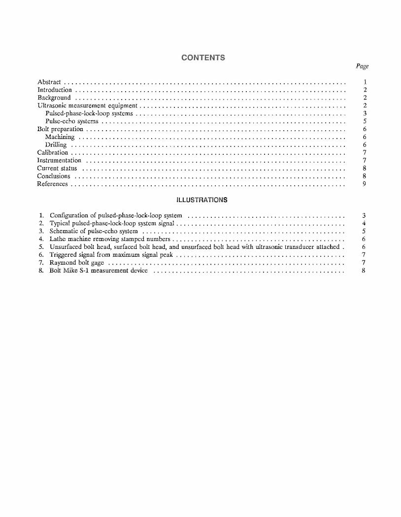
CONTENTS Page
Abstract. . . . . . . . . . . . . . . . . . . . . . . . . . . . . . . . . . . . . . . . . . . . . . . . . . . . . . . . . . . . . . . . . . . . . . . . . . . 1 Introduction . . . . . . . . . . . . . . . . . . . . . . . . . . . . . . . . . . . . . . . . . . . . . . . . . . . . . . . . . . . . . . . . . . . . . . . . 2 Background .. .. . .... . ............... . . .. .. ... ... ........................ . .......... 2 Ultrasonic measurement equipment . . . . . . . . . . . . . . . . . . . . . . . . . . . . . . . . . . . . . . . . . . . . . . . . . . . . . . . 2
Pulsed-phase-lock-loop systems . . . . . . . . . . . . . . . . . . . . . . . . . . . . . . . . . . . . . . . . . . . . . . . . . . . . . . . . 3 Pulse-echo syster!1s . . . . . . . . . . . . . . . . . . . . . . . . . . . . . . . . . . . . . . . . . . . . . . . . . . . . . . . . . . . . . . . . . 5
Bolt preparation . . . . . . . . . . . . . . . . . . . . . . . . . . . . . . . . . . . . . . . . . . . . . . . . . . . . . . . . . . . . . . . . . . . . . 6 Machining ............. . . . ........... . ........ . .. .. .............. . ... ... .. ... . . .. 6 Drilling ........... ............... . ...... . .. . ... . ... .. . . .............. . ... . .. . . .. 6
Calibration ................. . ............................................ , . . . . . . . . . . 7 Instrumentation ............ . ......... . ... .. ... ... ... .. .. . . ......... . . ............... 7 Current status ..................... . ............ . .. . ........... . . . ....... ... ........ 8 Conclusions ................................. .. . .. .... ... .. . ............... . ........ 8 References . . . . . . . . . . . . . . . . . . . . . . . . . . . . . . . . . . . . . . . . . . . . . . . . . . . . . . . . . . . . . . . . . . . . . . . . . 9
ILLUSTRATIONS
1. Configuration of pulsed-phase-lock-loop system ............. . .... . .. .. ....... .. .......... 3 2. Typical pulsed-phase-Iock-Ioop system signal. . . . . . . . . . . . . . . . . . . . . . . . . . . . . . . . . . . . . . . . . . . . . 4 3. Schematic of pulse-echo system ............................................ . .... .. ... 5 4. Lathe machine removing stamped numbers. . . . . . . . . . . . . . . . . . . . . . . . . . . . . . . . . . . . . . . . . . . . . . 6 5. Unsurfaced bolt head, surfaced bolt head, and unsurfaced bolt head with ultrasonic transducer attached. 6 6. Triggered signal from maximum signal peak. . . . . . . . . . . . . . . . . . . . . . . . . . . . . . . . . . . . . . . . . . . . . 7 7. Raymond bolt gage ..................................................... ... .. . .... 7 8. Bolt Mike S-l measurement device .......................................... .. ....... 8
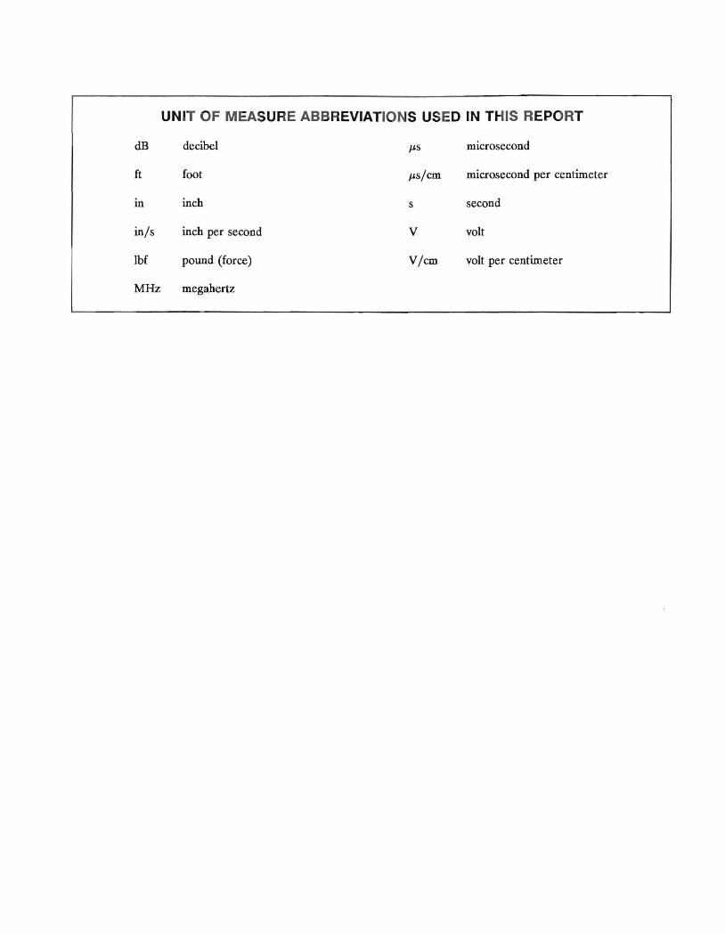
UNIT OF MEASURE ABBREVIATIONS USED IN THIS REPORT
dB decibel J.'s microsecond
ft foot J.'s/cm microsecond per centimeter
in inch s second
inls inch per second V volt
thf pound (force) Vlcm volt per centimeter
MHz megahertz
EVALUATION OF ULTRASONIC MEASUREMENT SYSTEMS FOR BOLT LOAD DETERMINATIONS
By Stephen C. Tadolini1
ABSTRACT
The U.S. Bureau of Mines has developed ultrasonic measurement instrumentation capable of measuring strains and elongations on tensioned and untensioned mine roof bolting systems. This report evaluates the pulsed-phase-Iock-Ioop and pulse-echo systems. The pulse-echo systems measure time of flight of a signal through the bolt. The ultrasonic instrument converts the measurement into elongations or stress. The most recent Bureau instrument development converts travel-time measurements directly into elongation, load, stress, and torque by simple data manipulation from the keyboard. Bolt preparation and instrument calibration are described in detail.
1Mining engineer, Denver Research Center, U.S. Bureau of Mines, Denver, CO.
INTRODUCTION
Millions of rock bolts, both tensioned and untensioned, arc used each year for structural support. The applications range from underground mining environments to geotechnical applications of tieback walls and canal lock support. An increasing percentage of these bolting systems utilize resin-anchor and resin-mechanical-anchor combination bolts as well as mechanical anchor bolts. The method by which expansion anchor bolting systems carry roof loads is well understood and documented. The
support capability of a given anchorage system installation depends on such factors as rock characterization, bolt characteristics, and bolt tension. Measurement of installation and postinstallation bolt tension provides a great deal of information about the effectiveness of the bolts and the behavior of the supported structure. This study was conducted as part of the u.s. Bureau of Mines program to improve safety in the mines.
BACKGROUND
Current practice in civil and mining environments is to use load cells, strain gages, pressure pads, or vibrating-wire m.struments to determine initial and subsequent bolt load. An obvious disadvantage of these types of instruments is that instrumented bolts receive special handling during the installation process. This may make it nonrepresentative of typically installed bolts. Also, the cost per bolt with these types of measurement systems is high.
Current practice in production is to use torque wrench readings on a small statistical sample of the bolts, as required by Federal regulations in the mining industry (9).2
This method has the disadvantage that torque measurements are only about ± 30% accurate as related to bolt load. The conversion of torque to load in the installation is also highly dependent on component shape, washers, lubrication, and installation thrust. The method may also disturb the anchorage that has been obtained in the immediate host rock, while the small sample gives only a vague indication of overall structural stability. Resingrouted or concrete-grouted bolts or supports cannot be tested with a torque wrench because the measurement would only reveal the torsional resistance of the steel.
ULTRASONIC MEASUREMENT EQUIPMENT
To overcome the measurement problems associated with the determination of bolt stability and integrity, ultrasonic measurement systems were investigated and adapted by the Bureau for use with tension and un tensioned support in the geotechnical and mining industries. These ultrasonic measurements provide an easy-to-use, high-accuracy, low-cost-per-bolt system that is capable of determining the amount of load being subjected on an installed support system.
The principle involved is simple. The round-trip travel time of a sonic pulse or group of sonic waves propagating through a bolt is measured. This travel time is affected by bolt stress and bolt strain and changes linearly to a fraction of a percent with respect to axial bolt loads. The waves are introduced into the bolt by a piezoelectric transducer attached at the bolt head, which also detects the return waves that have reflected back from the bolt end or other internal reflector, such as a small-diameter hole drilled orthogonal to the bolt axis.
2Italic numbers in parentheses refer to items in the list of references at the end of this report.
To accommodate strain gages or vibrating wires, modifications are necessary that can create zones of induced stress concentrations; these stress concentrations can produce erroneous test results, particularly at low stress levels. Such modifications are not necessary when using ultrasonic instruments. By measuring the axial deformation of a bolt · throughout its length, calculations can be made to determine the amount of load induced at these locations by the applied end-loading conditions. This information can provide a clearer understanding as to the overall loading characteristics of full- and partial-column resin-grouted bolts.
Making the required time measurements, however, is very complex because the changes in round-trip travel time are very small. To appreciate the electrical and mechanical complexity of the instrumentation problem, it is important to recognize that a typical 5/8-in-diam, 4-ft-long mine bolt stretches only 0.00064 in per 100 lbf of axial load. Considering that the signal makes a round trip (8 ft) through the bolt and that a typical signal velocity is 231,000 inls, causing the instrumentation to change at least
one unit for a 100-lbf change, time must be stably resolved to about 5.5 x 10⁻⁹ s at a typical probing frequency of 2.25 MHz. Any error source need only cause an equivalent change of the order of 0.02 Jjs to become a major difficulty. Signal attenuation is also severe, reaching about 80 dB for the described bolt. The near-field focal length of typical transducers at frequencies used is only a few inches. Beyond this, the wave front spreads out in a conical fashion. Since bolt signal paths are relatively long, the signal path is quite complex because the waves reflect off the sides of the bolt, become mode converted from P- to S-type waves and back, and constructively and destructively interfere (2).
The research in the ultrasonic field was undertaken by examining two fundamental approaches to the measurement. Pulsed-phase-Iock-loop (P2I}) systems were studied first. These systems measure time indirectly by shifting their probing frequency to maintain constant output to reflection wave-phase differences as the bolt loads. The frequency change, which is easy to measure, then becomes an indirect measure of time change. Pulse-echo systems were examined, evaluated, and selected for use in this investigation. These systems have the ability to measure travel time directly by incorporating special electronic techniques to provide the required time resolution (5).
PULSED-PHASE-LOCK-LOOP SYSTEMS
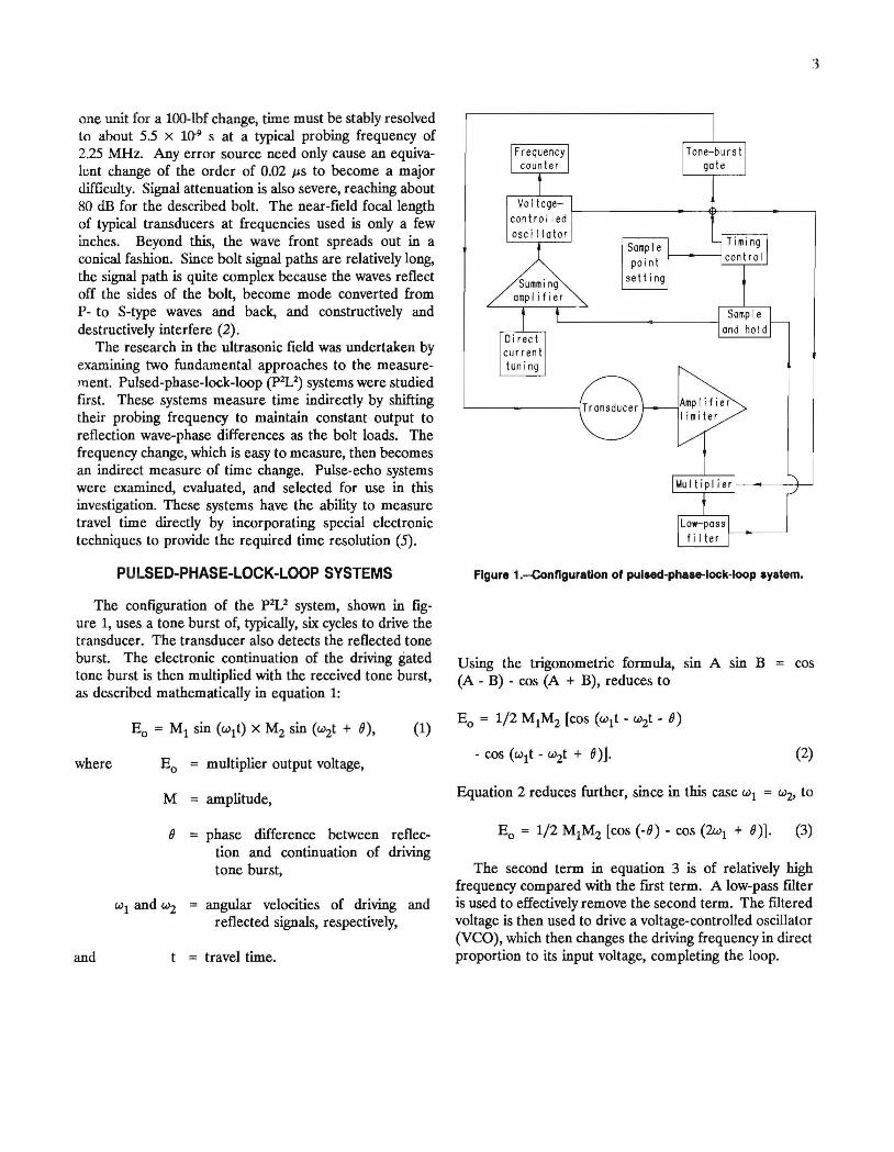
The configuration of the p2I} system, shown in figure 1, uses a tone burst of, typically, six cycles to drive the transducer. The transducer also detects the reflected tone burst. The electronic continuation of the driving gated tone burst is then multiplied with the received tone burst, as described mathematically in equation 1:
where
M
o
and
(1)
multiplier output voltage,
amplitude,
phase difference between reflection and continuation of driving tone burst,
angular velocities of driving and reflected signals, respectively,
travel time.
3
Vol tage-control I ed f----------+------,
oscillator
current tuning
Samp I e f-------I point c.:....:..;..~-'--J
setting
Figure 1.-ConfiguratJon of pulaed-phaae-Iock-Ioop system.
Using the trigonometric formula, sin A sin B (A - B) - cos (A + B), reduces to
cos
(2)
Equation 2 reduces further, since in this case WI = w2' to
Eo = 1/2 MIM2 [cos (-0) - cos (2wI + 0)]. (3)
The second term in equation 3 is of relatively high frequency compared with the first term. A low-pass fllter is used to effectively remove the second term. The futered voltage is then used to drive a voltage-controlled oscillator (VeO), which then changes the driving frequency in direct proportion to its input voltage, completing the loop.
4
The loop locks with the two signals in quadrature. The locking tendency of the loop can be discovered by considering perturbations from 8 = 90°. Assume the phase difference increases in magnitude from 90°. Then cos (- 8), which is in the third quadrant, will reduce from o toward -1. The YCO input voltage will then decrease. This reduces the driving frequency, which reduces 8, since the origin of the output tone burst is flxed in time, and the reflection arrival time does not vary with frequency. This continues until 8 returns to 90°. Assume the phase difference decreases from 90°. Then cos (-8), which is now in the fourth quadrant, will increase from 0 toward 1. The YCO input voltage will then increase. This raises the driving frequency, which increases 8. Again this continues until 8 = 90°. Thus, the loop locks in quadrature. The total travel time of the tone burst can be described in terms of a total phase angle: ¢ = N x 360° + 8, where N is the whole number of cycles between the tone burst initiation and the start of the reflection:
(4)
where F the frequency,
and subscript i initial value.
Consider now that the bolt will be stretched while the loop is locked, so the [mal ¢ is as follows:
where subscript f = [mal value,
subtracting
(5)
(6)
As discussed previously, the action of the p2V is to keep the phase constant, so
(7)
so from
Subtracting Fjtj and dividing both sides by M reduces to
(9)
Again, substituting Ff = Fi + ~F and simplifying equa· tion 9 reduces further to
(10)
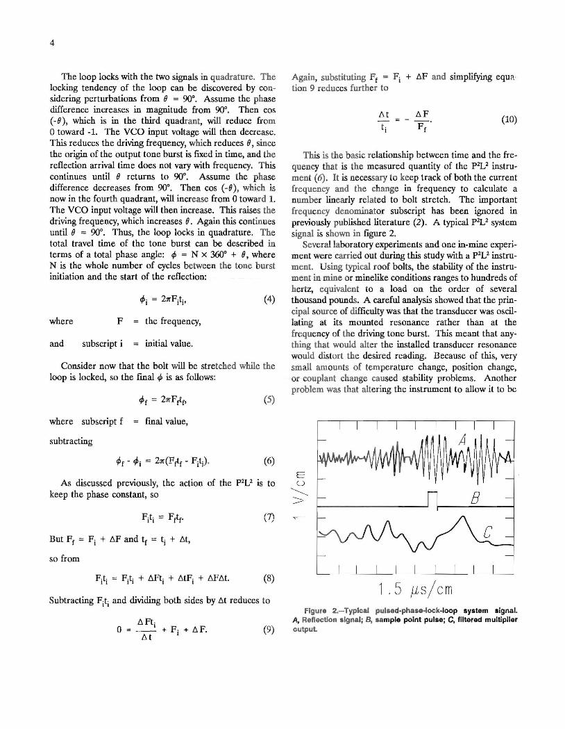
This is the basic relationship between time and the frequency that is the measured quantity of the pzV instrument (6). It is necessary to keep track of both the current frequency and the change in frequency to calculate a number linearly related to bolt stretch. The important frequency denominator subscript has been ignored in previously published literature (2). A typical p2J} system signal is shown in flgure 2.
Several laboratory experiments and one in-mine experiment were carried out during this study with a p 2L2 instrument. Using typical roof bolts, the stability of the instrument in mine or minelike conditions ranges to hundreds of hertz, equivalent to a load on the order of several thousand pounds. A careful analysis showed that the principal source of difficulty was that the transducer was oscillating at its mounted resonance rather than at the frequency of the driving tone burst. This meant that anything that would alter the installed transducer resonance would distort the desired reading. Because of this, very small amounts of temperature change, position change, or couplant change caused stability problems. Another problem was that altering the instrument to allow it to be
1. 5 f1s / cm Figure 2.-Typlcal pulsed-phase-Iock-loop system signal.
A, Reflection signal; B, sample point pulse; C, filtered multiplier output
portable and gassy-mine permissible would present significant electronic problems.
These problems are explained in detail in a Bureau Report of Investigations, which provides a complete analysis of P2L2 systems (4). For these reasons, further research on the P2L2 technology for bolt load measurement applications was given a very low emphasis. A parallel research effort has shown that the mine bolt load measurement can be satisfactorily made using pulse-echo technology.
PULSE-ECHO SYSTEMS
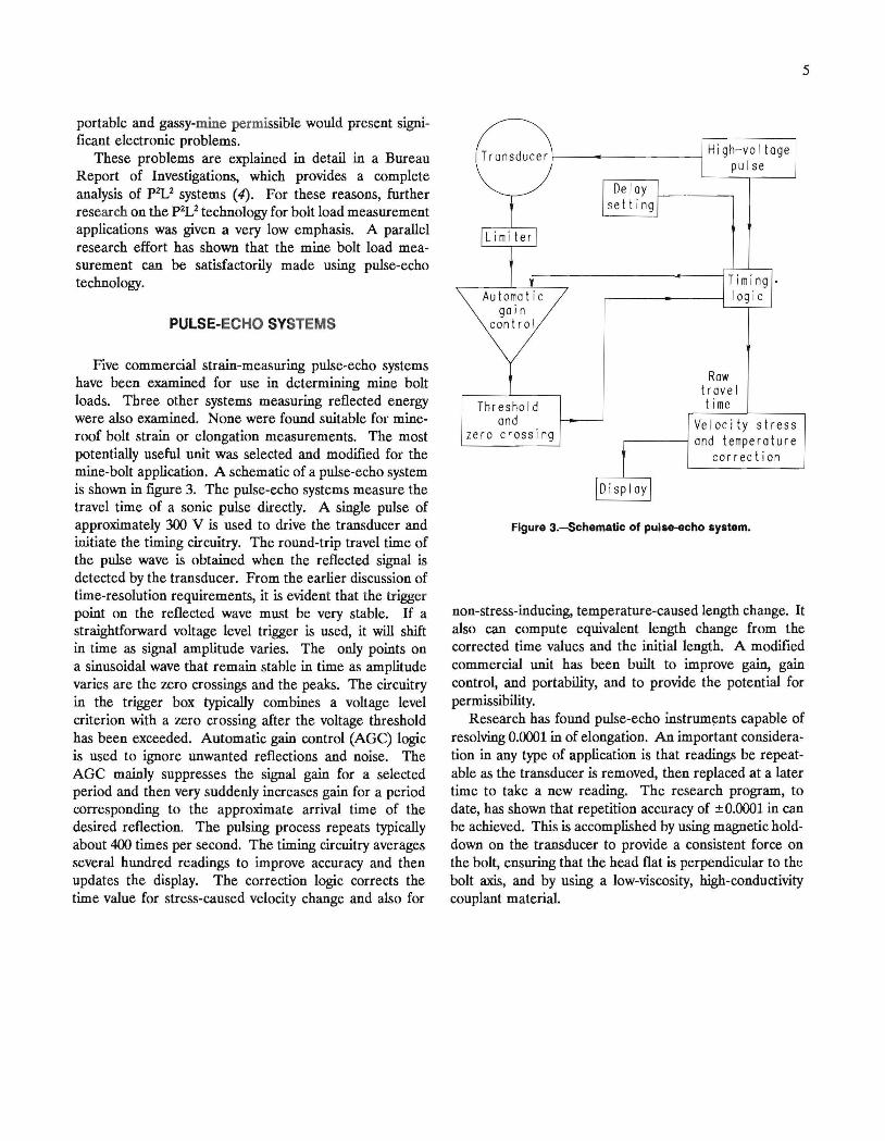
Five commercial strain-measuring pulse-echo systems have been examined for use in determining mine bolt loads. Three other systems measuring reflected energy were also examined. None were found suitable for mineroof bolt strain or elongation measurements. The most potentially useful unit was selected and modified for the mine-bolt application. A schematic of a pulse-echo system is shown in figure 3. The pulse-echo systems measure the travel time of a sonic pulse directly. A single pulse of approximately 300 V is used to drive the transducer and initiate the timing circuitry. The round-trip travel time of the pulse wave is obtained when the reflected signal is detected by the transducer. From the earlier discussion of time-resolution requirements, it is evident that the trigger point on the reflected wave must be very stable. If a straightforward voltage level trigger is used, it will shift in time as signal amplitude varies. The only points on a sinusoidal wave that remain stable in time as amplitude varies are the zero crossings and the peaks. The circuitry in the trigger box typically combines a voltage level criterion with a zero crossing after the voltage threshold has been exceeded. Automatic gain control (AGe) logic is used to ignore unwanted reflections and noise. The AGe mainly suppresses the signal gain for a selected period and then very suddenly increases gain for a period corresponding to the approximate arrival time of the desired reflection. The pulsing process repeats typically about 400 times per second. The timing circuitry averages several hundred readings to improve accuracy and then updates the display. The correction logic corrects the time value for stress-caused velocity change and also for
I-__ ~ _____ High-vol tage
Threshold and
zero crossing
pulse
Row travel time
Velocity stress r---~ and temperature
correction
Figure 3.--Schematic of pulle-echo system.
5
non-stress-inducing, temperature-caused length change. It also can compute equivalent length change from the corrected time values and the initial length. A modified commercial unit has been built to improve gain, gain control, and portability, and to provide the potential for permissibility.
Research has found pulse-echo instruments capable of resolving 0.0001 in of elongation. An important consideration in any type of application is that readings be repeatable as the transducer is removed, then replaced at a later time to take a new reading. The research program, to date, has shown that repetition accuracy of ± 0.0001 in can be achieved. This is accomplished by using magnetic holddown on the transducer to provide a consistent force on the bolt, ensuring that the head flat is perpendicular to the bolt axis, and by using a low-viscosity, high-conductivity couplant material.
BOLT PREPARATION
MACHINING
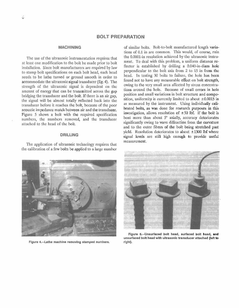
The use of the ultrasonic instrumentation requires that at least one modification to the bolt be made prior to bolt installation. Since bolt manufacturers are required by law to stamp bolt specifications on each bolt head, each head needs to be lathe turned or ground smooth in order to accommodate the ultrasonic signal transducer (fig. 4). The strength of the ultrasonic signal is dependent on the ~o~nt of energy that can be transmitted across the gap bndgmg the transducer and the bolt. If there is an air gap, the signal will be almost totally reflected back into the transducer before it reaches the bolt, because of the poor acoustic impedance match between air and the transducer. Figure 5 shows a bolt with the required specification numbers, the numbers removed, and the transducer attached to the head of the bolt.
DRILLING
The application of ultrasonic technology requires that the calibration of a few bolts be applied to a large number
Figure 4.-lathe machine removing stamped numbers.
of similar bolts. Bolt-to-bolt manufactured length variations of 0.1 in are common. This would, of course, ruin the O.OOOl-in resolution achieved by the ultrasonic instrument. To deal with this problem, a uniform distance reflector is established by drilling a O.04O-in-diam hole perpendicular to the bolt axis from 2 to 15 in from the head. In testing 30 bolts to failure, the hole has been found not to have any measurable effect on bolt strength, owing to the very small area affected by stress concentrations around the hole. Because of small errors in hole position and small variations in bolt structure and composition, uniformity is currently limited to about ± 0.0015 in as measured by the instrument. Using individually calibrated bolts, as was done for research purposes in this investigation, allows resolution of ± 50 lbf. If the bolt is bent more than about 50 axially, accuracy deteriorates significantly owing to wave diffraction from the curvature and to the outer fibers of the bolt being stretched past yield. Resolution deteriorates to about ± 1300 lbf where signal levels are still high enough to provide useful measurement.
Figure 5.-Unsurfaced bolt head, surfaced bolt head, and unsurfaced bolt head with ultrasonic transducer attached (left to right).
7
CALIBRATION
To perform accurate measurements, the initial length of the reflector signal and the sonic velocity of the bolt material must be known. The sonic velocity is set by applying the instrument to a bolt stub of known length and then adjusting its velocity setting until the instrument reading equals the known length. Next, the initial head-toreflector distance in an unloaded bolt is measured using the ultrasonic instrument with the velocity setting previously calibrated. Finally, the velocity change with load is calibrated by setting a stress factor · in the
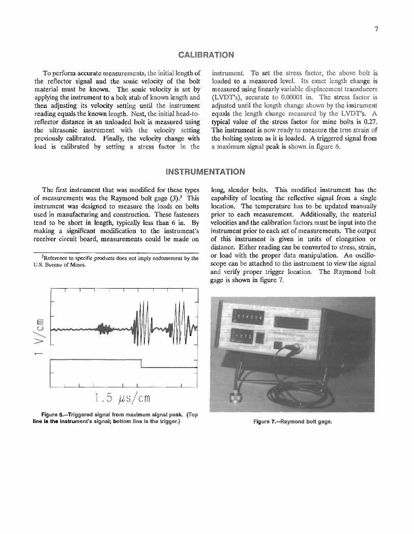
instrument. To set the stress factor, the above bolt is loaded to a measured level. Its exact length change is measured using linearly variable displacement transducers (LVDT's), accurate to 0.00001 in. The stress factor is adjusted until the length change shown by the instrument equals the length change measured by the L VDT's. A typical value of the stress factor for mine bolts is 0.27. The instrument is now ready to measure the true strain of the bolting system as it is loaded. A triggered signal from a maximum signal peak is shown in figure 6.
INSTRUMENTATION
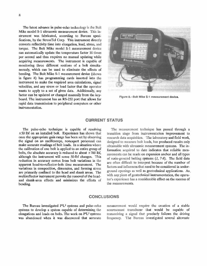
The first instrument that was modified for these types of measurements was the Raymond bolt gage (3).3 This instrument was designed to measure the loads on bolts used in manufacturing and construction. These fasteners tend to be short in length, typiC<lHy less than 6 in. By making a significant modification to the instrument's receiver circuit board, measurements could be made on
3Reference to specific products does not imply endorsement by the U.S. Bureau of Mines.
E U ~ >
1.5fLs/ cm Figure 6.-Triggered signal from maximum signal peak. (Top
line Is the Instrument's signal; bottom line Is the trigger.)
long, slender bolts. This modified instrument has the capability of locating the reflective signal from a single location. The temperature has to be updated manually prior to each measurement. Additionally, the material velocities and the calibration factors must be input into the instrument prior to each set of measurements. The output of this instrument is given in units of elongation or distance. Either reading can be converted to stress, strain, or load with the proper data manipulation. An oscilloscope can be attached to the instrument to view the signal and verify proper trigger location. The Raymond bolt gage is shown in figure 7.
Figure 7.-Raymond bolt gage.
8
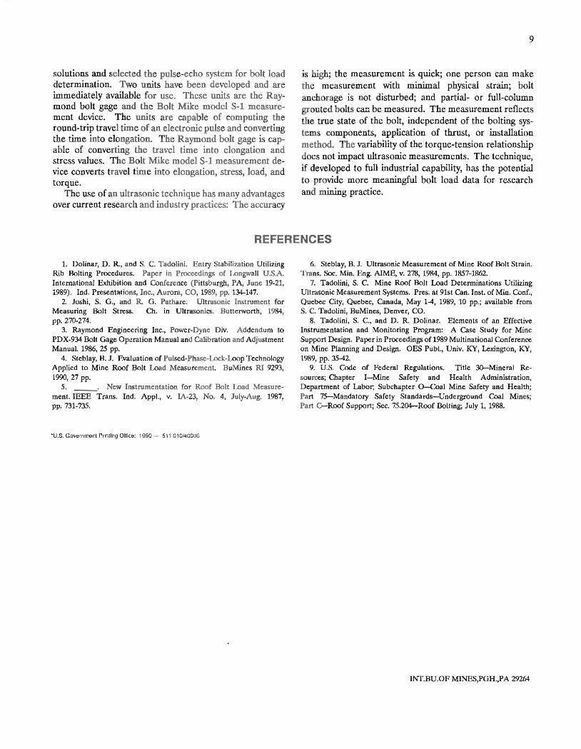
The latest advance in pulse-echo technology is the Bolt Mike model S-l ultrasonic measurement device. This instrument was fabricated, according to Bureau specifications, by the StressTel Corp. This instrument directly converts reflectivity time into elongation, load, stress, and torque. The Bolt Mike model S-l measurement device can automatically update the temperature factor 10 times per second and thus requires no manual updating while acquiring measurements. The instrument is capable of monitoring three different sections of a bolt simultaneously, which can be used to eliminate the effects of bending. The Bolt Mike S-l measurement device (shown in figure 8) has programming cards inserted into the instrument to make the required area calculations, signal velocities, and any stress or load factor that the operator wants to apply to a set of given data. Additionally, any factor can be updated or changed manually from the keyboard. The instrument has an RS-232 port that allows for rapid data transmission to peripheral computers or other instrumentation.
Figure 8.-Bolt Mike 5-1 measurement device.
CURRENT STATUS
The pulse-echo technique is capable of resolving ± 50 lbf on an installed bolt. Experience has shown that once the appropriate gain range has been set by observing the signal on an oscilloscope, nonexpert personnel can make accurate readings of bolt loads. In a situation where the calibration of one bolt is applied to an entire group of bolts, the absolute accuracy is reduced to about ± 700 lbf, although the instrument will sense 50-lbf changes. This reduction in accuracy comes from bolt variations in the apparent head-to-reflector-hole time measurement. The variations in composition, dimension, and forming stress are primarily confined to the head and shank areas. The multireflector instrument permits the removal of the headand shank-area effects and minimizes the effects of bending.
The measurement technique has passed through a transition stage from instrumentation improvement to research data acquisition. The laboratory and field work, designed to measure bolt loads, has produced results only obtainable with ultrasonic measurement systems. The information acquired to date indicates that reliable measurements can be made on expansion anchor and all types of resin-grouted bolting systems (1, 7-8). The field data are often difficult to interpret because of the number of factors and influences that need to be considered in underground openings as well as geotechnical applications. As . with any piece of geotechnical instrumentation, the operator's experience has a considerable effect on the success of the measurements.
CONCLUSIONS
The Bureau investigated pzv systems and pulse-echo systems to develop a system capable of determining the elongations and loads on bolts. The work on pzv systems was abandoned when it was discovered that accurate
measurement would require the creation of a stable nonresonant transducer that would be capable of transceiving a signal that precisely follows the driving frequency. The Bureau investigated several alternate
solutions and selected the pulse-echo system for bolt load determination. Two units have been developed and are immediately available for use. These units are the Raymond bolt gage and the Bolt Mike model S-1 measurement device. The units are capable of computing the round-trip travel time of an electronic pulse and converting the time into elongation. The Raymond bolt gage is capable of converting the travel time into elongation and stress values. The Bolt Mike model S-1 measurement device converts travel time into elongation, stress, load, and torque.
The use of an ultrasonic technique has many advantages over current research and industry practices: The accuracy
9
is high; the measurement is quick; one person can make the measurement with minimal physical strain; bolt anchorage is not disturbed; and partial- or full-column grouted bolts ~ be measured. The measurement reflects the true state of the bolt, independent of the bolting systems components, application of thrust, or installation method. The variability of the torque-tension relationship does not impact ultrasonic measurements. The technique, if developed to full industrial capability, has the potential to provide more meaningful bolt load data for research and mining practice.
REFERENCES
1. Dolinar, D . R, and S. C. Tadolini. Entry Stabilization U tilizing Rib Bolting Procedures. Paper in Proceedings of Longwall U.SA. International Exhibition and Conference (Pittsburgh, PA, June 19-21, 1989). Ind. Presentations, Inc., Aurora, CO, 1989, pp. 134-147.
2. Joshi, S. G., and R G. Pathare. Ultrasonic Instrument for Measuring Bolt Stress. Ch. in Ultrasonics. Butterworth, 1984, pp. 270-274.
3. Raymond Engineering Inc., Power-Dyne D iv. Addendum to PDX-934 Bolt Gage Operation Manual and Calibration and A djustment Manual. 1986, 25 pp.
4. Steblay, B. J. Evaluation of Pulsed-Phase-Lock-Loop Technology Applied to Mine Roof Bolt Load Measurement. BuMines RI 9293, 1990,27 pp.
5. __ . New Instrumentation for Roof Bolt Load Measurement . IEEE Trans. Ind. Appl., v. lA-23, No.4, July-Aug. 1987, pp.731-735.
·U.S. Govern ment Printing Office: t 990 - 511·010140006
6. Steblay, B. J. Ultrasonic Measurement of Mine Roof Bolt Strain. Trans. Soc. Min. Eng. AIME, v. 278, 1984, pp. 1857-1862.
7. Tadolini, S. C. Mine Roof Bolt Load Detenninations Utilizing Ultrasonic Measurement Systems. Pres. at 91st Can. Inst. of Min. Cone., Quebec City, Quebec, Canada, May 1-4, 1989, 10 pp.; available from S. C. Tadolini , BuMines, Denver, CO.
8. Tadolini, S. c., and D. R Dolinar. Elements of an Effective Instrumentation and Monitoring Program: A Case Study for Mine Support Design. Paper in Proceedings of 1989 Multinational Conference on Mine Planning and Design. OES Publ., Univ. KY, Lexington, KY, 1989, pp. 35-42.
9. U .S. Code of Federal Regulations. Title 3O--Mineral Resources; Chapter I-Mine Safety and Health Administration, Department of Labor; Subchapter O-Coal Mine Safety and Health; Part 75-Mandatory Safety Standards-Underground Coal Mines; Part C-Roof Support; Sec. 75.204-Roof Bolting; July I, 1988.
INT.BU.OF MINES,PGH.,PA 29264
Top Related