


Languages
Pages
Legal

Evaluation of the situation of cores and containment vessels of Fukushima Daiichi
Nuclear Power Station Units-1 to 3 and examination into unsolved issues
in the accident progression
― Progress Report No. 1 ―
December 13, 2013Tokyo Electric Power Co., Inc.
1
Preface
Based on surveys and analysis relating to the Fukushima Nuclear Power Station accident, TEPCO considers that many items pertaining to the causes and development of the accident are now clear.
At present, however, remaining records and on-site investigations are still limited,and there are still some aspects that remain unconfirmed or unexplained with regard to the locations, the extent and the causes of the damage to the Fukushima Daiichi Nuclear Power Station, arising from the development of the accidents that followed the Tohoku Region Pacific Coast Earthquake.
As the main party responsible for the Fukushima Nuclear Power Station accident, TEPCO will continue to conduct systematic on-site surveys and simulation analysis aimed at gaining a clear understanding of all aspects of the behavior of the nuclear reactors during the accident. We consider that this will prove useful in fulfilling our obligation as the operator of the Nuclear Power Station to improve safety, and to aid the work of decommissioning the plant.
As the first progress report, this report focuses on the unconfirmed and unexplained issues from immediately after the accident through to the end of March 2011.

2
Preface
■ Overview1. Objective of survey and study of unconfirmed and unexplained events2. Overview (approach to unconfirmed and unexplained events)
(organizing, extracting issues and approach to studies) (overview of first progress report)
■Main Report1. Approach to unconfirmed and unexplained events (1) Extraction range for unconfirmed and unexplained events(2) Explained events(3) Classifying and organizing the extraction of extracted unconfirmed and unexplained events2. Unconfirmed and unexplained events for which studies have been completed3. Detailed examination of representative unconfirmed and unexplained events (1) Primary causes for the loss of cooling function(2) The possibility that the flooding in the Unit 1 reactor building might be water leakage from important equipment due to the earthquake (3) Reasons why the reactor was not sufficiently cooled, despite water being sprayed in from fire trucks(4) Reason for the discrepancy between the time of manual stoppage of the high-pressure coolant injection system in unit 3 and internal reactor data(5) Cause of the sudden decrease in reactor pressure in unit 3 (whether there was a hole in the reactor or other important equipment) 4. Estimated state of the reactor and containment vessel (unit 3)5. Major issues for future examination
Contents
P4P5P6P7
P9P10P11P12
P13P19
P24
P28
P32P37P38

Report on the survey and study results of unconfirmed and unexplained events of the Fukushima Nuclear Power
Station accident
Overview
4
As the operator of the nuclear power station and the main party responsible for the accident, we are fully committed to clarifying all
aspects of the accident
As the operator of the nuclear power station and the main party responsible for the accident, we are fully committed to clarifying all
aspects of the accident
Solving reactor decommissioning issues and accumulating information
Solving reactor decommissioning issues and accumulating information
Improvement in safety measures and heightened safety at Kashiwazaki-Kariwa Nuclear Power Station
Improvement in safety measures and heightened safety at Kashiwazaki-Kariwa Nuclear Power Station
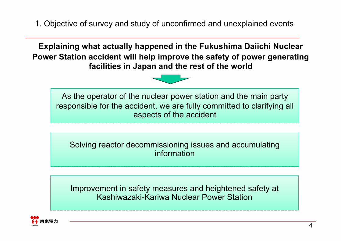
1. Objective of survey and study of unconfirmed and unexplained events
Explaining what actually happened in the Fukushima Daiichi Nuclear Power Station accident will help improve the safety of power generating
facilities in Japan and the rest of the world

5
From a broad range of perspectivesAssigning unconfirmed and unexplained events to the two categories below
(Target period: To the end of March 2011)
Understanding the status of the reactor cores and containment vessels and the main flow of accident
development
Understanding the status of the reactor cores and containment vessels and the main flow of accident
development
Accumulating the information needed for detailed understanding and assessment of the
development of the accident
Accumulating the information needed for detailed understanding and assessment of the
development of the accident
Example) Confirming the state of the residual heat removal system in unit 2 before and after the tsunami
[Reason]We need to confirm the cooling status of this system, and this may also help to improve safety, such as by providing knowledge that will help to prevent accidents.
Example) Confirming the state of the residual heat removal system in unit 2 before and after the tsunami
[Reason]We need to confirm the cooling status of this system, and this may also help to improve safety, such as by providing knowledge that will help to prevent accidents.
2. Overview (approach to unconfirmed and unexplained events)
Example 1) Cause of loss of cooling system function in isolating the reactors
Example 2) Details that observations during the accident cannot fully explain and issues we cannot explain
Example 1) Cause of loss of cooling system function in isolating the reactors
Example 2) Details that observations during the accident cannot fully explain and issues we cannot explain
Note: Issues regarding the emission of radioactive material outside the plant have been detailed in the report, “Radioactive material released into the atmosphere in the Fukushima Daiichi Nuclear Power Station accident”, published in May 2012. This report will mainly focus on explaining the development of the accident.
6
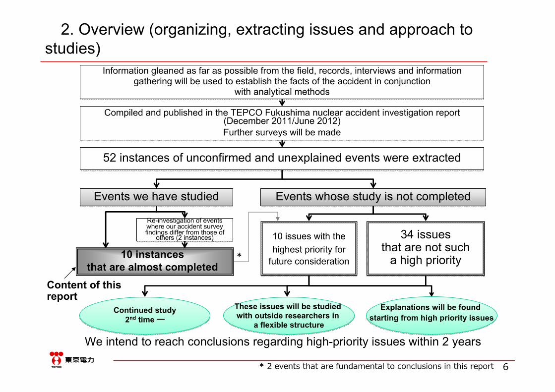
2. Overview (organizing, extracting issues and approach to studies)
Information gleaned as far as possible from the field, records, interviews and informationgathering will be used to establish the facts of the accident in conjunction
with analytical methods
Information gleaned as far as possible from the field, records, interviews and informationgathering will be used to establish the facts of the accident in conjunction
with analytical methods
Compiled and published in the TEPCO Fukushima nuclear accident investigation report (December 2011/June 2012)Further surveys will be made
Compiled and published in the TEPCO Fukushima nuclear accident investigation report (December 2011/June 2012)Further surveys will be made
52 instances of unconfirmed and unexplained events were extracted52 instances of unconfirmed and unexplained events were extracted
Events we have studiedEvents we have studied Events whose study is not completedEvents whose study is not completed
10 issues with the highest priority for
future consideration
10 issues with the highest priority for
future consideration
34 issuesthat are not such
a high priority
34 issuesthat are not such
a high priority
Content of this report
Re-investigation of events where our accident survey findings differ from those of
others (2 instances)
Re-investigation of events where our accident survey findings differ from those of
others (2 instances)
10 instances that are almost completed
*
* 2 events that are fundamental to conclusions in this report
Continued study2nd time ―
Continued study2nd time ―
These issues will be studied with outside researchers in
a flexible structure
These issues will be studied with outside researchers in
a flexible structure
Explanations will be found starting from high priority issues
Explanations will be found starting from high priority issues
We intend to reach conclusions regarding high-priority issues within 2 years
7
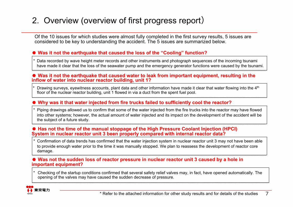
* Checking of the startup conditions confirmed that several safety relief valves may, in fact, have opened automatically. The opening of the valves may have caused the sudden decrease of pressure.
* Checking of the startup conditions confirmed that several safety relief valves may, in fact, have opened automatically. The opening of the valves may have caused the sudden decrease of pressure.
Of the 10 issues for which studies were almost fully completed in the first survey results, 5 issues are considered to be key to understanding the accident. The 5 issues are summarized below.
2. Overview (overview of first progress report)
* Refer to the attached information for other study results and for details of the studies
* Data recorded by wave height meter records and other instruments and photograph sequences of the incoming tsunami have made it clear that the loss of the seawater pump and the emergency generator functions were caused by the tsunami.
* Data recorded by wave height meter records and other instruments and photograph sequences of the incoming tsunami have made it clear that the loss of the seawater pump and the emergency generator functions were caused by the tsunami.
* Drawing surveys, eyewitness accounts, plant data and other information have made it clear that water flowing into the 4th
floor of the nuclear reactor building, unit 1 flowed in via a duct from the spent fuel pool.* Drawing surveys, eyewitness accounts, plant data and other information have made it clear that water flowing into the 4th
floor of the nuclear reactor building, unit 1 flowed in via a duct from the spent fuel pool.
* Piping drawings allowed us to confirm that some of the water injected from the fire trucks into the reactor may have flowed into other systems; however, the actual amount of water injected and its impact on the development of the accident will be the subject of a future study.
* Piping drawings allowed us to confirm that some of the water injected from the fire trucks into the reactor may have flowed into other systems; however, the actual amount of water injected and its impact on the development of the accident will be the subject of a future study.
● Was it not the earthquake that caused the loss of the “Cooling” function?
● Was it not the earthquake that caused water to leak from important equipment, resulting in the inflow of water into nuclear reactor building, unit 1?
● Why was it that water injected from fire trucks failed to sufficiently cool the reactor?
● Has not the time of the manual stoppage of the High Pressure Coolant Injection (HPCI) System in nuclear reactor unit 3 been properly compared with internal reactor data?
● Was not the sudden loss of reactor pressure in nuclear reactor unit 3 caused by a hole in important equipment?
* Confirmation of data trends has confirmed that the water injection system in nuclear reactor unit 3 may not have been able to provide enough water prior to the time it was manually stopped. We plan to reassess the development of reactor core damage.
* Confirmation of data trends has confirmed that the water injection system in nuclear reactor unit 3 may not have been able to provide enough water prior to the time it was manually stopped. We plan to reassess the development of reactor core damage.
Report on the survey and study results of unconfirmed and unexplained events of the Fukushima Nuclear Power
Station accident
Main Report

9
1. Approach to unconfirmed and unexplained events(1) Extraction range for unconfirmed and unexplained events
The designated ranges are from ① to ⑤ below (primarily for actual correlations) and from ① to ⑨ (primarily for the development of the accident, the damage processes, etc.)The designated ranges are from ① to ⑤ below (primarily for actual correlations) and from ① to ⑨ (primarily for the development of the accident, the damage processes, etc.)
Pre-accident statusPre-accident status Post-accident statusPost-accident status
給水系 CS系
Time course
⑦Reactor dam
age
⑧Release of radioactive m
aterials
⑨Containm
ent vessel damage
⑥Reactor behavior
Range①
Range ②
* "Accident investigation report" reference URL: http://www.tepco.co.jp/cc/press/2012/1205628_1834.html
Because the views of TEPCO and those expressed in external accident investigation reports differ in part, surveys are ongoing.
Studies will be conducted aimed at organizing, extracting and explaining unexplained issues, such as the detailed behavior of the equipment in steps ⑤ and ⑥ of the accident development, the reactor and containment vessel damage processes in steps ⑦ to ⑨, and their post-accident statuses.
③Equipment dam
age
④Control by operators
②Tsunami
⑤Equipm
ent operation
①Earthquake
End of March 201111 March 2011
Fuel rods(approx. 4 m)
Reactorpressurevessel
ReactorcontainmentvesselSteam
Water
To Turbine building
Reactor buildingTo exhaust pipe
Valve
WaterWater
Height approx. 32 m
Water
Fuel rods
CSsyste
mWatersupplysystem

10
Loss of DC power due to the tsunamiEquipment control/measurement
became impossible
Maintain DC power during accidents
1. Approach to unconfirmed and unexplained events(2) Explained events
● Analysis of the processes starting from just after the earthquake through to the most severe events using an "event tree". Organization of the characteristics of accident development from Unit 1 to Unit 3.● Identifying the factors and causes leading to the loss of function in the safety equipment, and the application of measures to improve safety
● Analysis of the processes starting from just after the earthquake through to the most severe events using an "event tree". Organization of the characteristics of accident development from Unit 1 to Unit 3.● Identifying the factors and causes leading to the loss of function in the safety equipment, and the application of measures to improve safety
[What is event tree analysis?] A safety assessment method that analyzes the processes from the initial event that triggers the accident through to the finalstatus by developing a branching structure (tree). The tree branches at each stage based on criteria such as whether safetyequipment functions, allowing the characteristics of the accident to be organized.
起因事象 原子炉停止 直流電源 炉心冷却 交流電源復旧 炉心状態 格納容器制御 原子炉建屋制御等 終状態
地震(東北太平洋沖地震)
原子炉スクラム(地震加速度大)
外部電源 非常用DG DC電源 1号機:IC2/3号機:RCIC、HPCI
外部電源,非常用DG,電源融通
RPV減圧(代替策含)
原子炉注水(代替策含)
RHR RHR復旧 冷温停止,炉心損傷,PCV破損,等
PCVベント SGTS,換気,ベント弁開維持他
冷温停止,炉心損傷,PCV破損等
冷温停止
冷温停止
(A)
PCV破損
成功
失敗
(A)へ
(A)へ
RCIC/HPCI
格納容器は健全なものの、過熱等の原因でFPの漏えいが発生
成功 冷温停止(長期冷却必要)
FPの漏えいと水素爆発の発生
1F-3
炉心損傷
過圧による格納容器破損
炉心損傷
(A)へ
冷温停止(長期冷却必要)
格納容器は健全なものの、過熱等の原因でFPの漏えいが発生
1F-2
FPの漏えいと水素爆発の発生
炉心損傷
1F-1,2
FPの大量放出
炉心損傷
(A)へ
1F-1 冷温停止(長期冷却必要)
格納容器は健全なものの、過熱等の原因でFPの漏えいが発生
FPの漏えいと水素爆発の発生
炉心損傷
失敗
炉心損傷 過圧による格納容器破損
交流電源 長期的な冷温停止の確保
RCIC
失敗 (Xによる影響)
ET H
T
T
T
HT
HT
P
P
S
S
S
P
ETP
HS
: 地震による影響
: 津波による影響
: 交流電源もしくは直流電源の喪失による影響
: 終的な熱の逃し場の喪失による影響
: 水素爆発の発生による影響
T
T
P
P
P
3号機の最終形態
2号機の最終形態
1号機の最終形態
?
?
X
P
P?
E
E
X
E
成功 (ただし、Xによる影響で 困難が生じた場合も含む)
[Event tree image][Example of safety improvement measures using event tree analysis]
Understanding theUnderstanding thecauses of function loss
Install watertight doors in areaswith DC power installed
Install backup batteriesand dedicated
chargers in elevated locations
Function lossFunction lossprevention measureprevention measure
AlternativeAlternativesecurity measuresecurity measure
Safety assuranceSafety assurance
Application as a function loss countermeasure
at the Kashiwazaki-Kariwa Nuclear Power Station
Application as a function loss countermeasure
at the Kashiwazaki-Kariwa Nuclear Power Station

11
1. Approach to unconfirmed and unexplained events(3) Classifying and organizing the extraction of unconfirmed and unexplained events
The organization and extraction of unconfirmed and unexplained issues with the aim of fully clarifying the development of the accident, including events that are difficult to explain, events that
unfolded over a long period, and events that require wide-ranging argument within the scientific community.
Improved equipment reliability and operating procedures
More accurate estimation of the state inside the core and containment vessels
-- Classifying and organizing the extraction of unconfirmed and unexplained events --
-- Application of the study findings --
Understanding the state inside the core and containment vessels
Points raised by experts, such as
the report from the Investigation Commission
appointed by Diet
Equipment operating states and
details of the reasons why they stopped
The mechanisms of the earthquake and
tsunami,and their effects
Points that cannot be fully
explained regarding the observed
facts during the accident
Core damage processes
and the radioactive material
release processes
Useful in further improving safety andaccurately assessing accident
development behavior
Useful in further improving safety andaccurately assessing accident
development behaviorUseful in formulating efficient
decommissioning policyUseful in formulating efficient
decommissioning policy
12
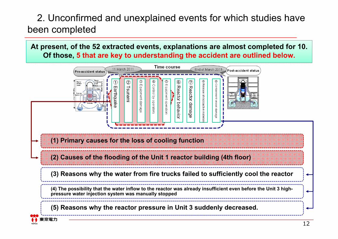
2. Unconfirmed and unexplained events for which studies have been completed
At present, of the 52 extracted events, explanations are almost completed for 10.Of those, 5 that are key to understanding the accident are outlined below.
At present, of the 52 extracted events, explanations are almost completed for 10.Of those, 5 that are key to understanding the accident are outlined below.
(1) Primary causes for the loss of cooling function
(2) Causes of the flooding of the Unit 1 reactor building (4th floor)
(3) Reasons why the water from fire trucks failed to sufficiently cool the reactor
(4) The possibility that the water inflow to the reactor was already insufficient even before the Unit 3 high-pressure water injection system was manually stopped
(5) Reasons why the reactor pressure in Unit 3 suddenly decreased.

13
3. Typical details of the studies into unconfirmed and unexplained events
(1) Primary causes for the loss of cooling function
Verification of the high likelihood that the loss of emergency cooling and emergency generator function was caused by the tsunami rather than the earthquake
Verification of the high likelihood that the loss of emergency cooling and emergency generator function was caused by the tsunami rather than the earthquake
-- Understanding and verifying the facts regarding the arrival of the tsunami at the site --
The time difference between the arrival of the tsunami at the site and the loss of emergencygeneration function (the events are simultaneous)
The time difference between the arrival of the tsunami at the site and the loss of emergencygeneration function (the events are simultaneous)
The sequence of function loss in equipment within the grounds of the Fukushima DaiichiNuclear Power Station (function lost sequentially starting from the ocean side)
The sequence of function loss in equipment within the grounds of the Fukushima DaiichiNuclear Power Station (function lost sequentially starting from the ocean side)
Analysis of the timing of the consecutive photography of the scene of the tsunami impactAnalysis of the timing of the consecutive photography of the scene of the tsunami impact
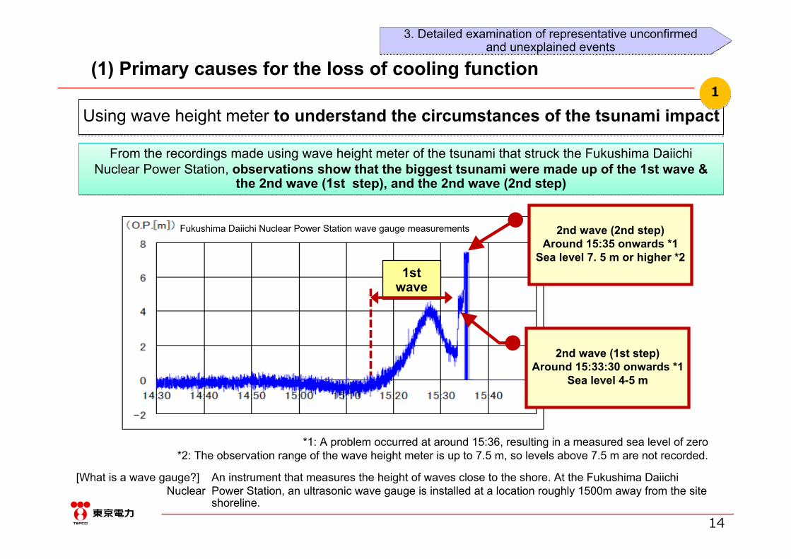
Using wave height meter at the Fukushima Daiichi nuclear power plantto understand the circumstances of the tsunami impact
Using wave height meter at the Fukushima Daiichi nuclear power plantto understand the circumstances of the tsunami impact
Using consecutive photography of the scene of the tsunami impactto analyze the timeline of the tsunami arrival
Using consecutive photography of the scene of the tsunami impactto analyze the timeline of the tsunami arrival
-- Key study points aimed at verification and explanation --
11
22
33
44
55
14
Using wave height meter to understand the circumstances of the tsunami impactUsing wave height meter to understand the circumstances of the tsunami impact11
1st wave
*1: A problem occurred at around 15:36, resulting in a measured sea level of zero*2: The observation range of the wave height meter is up to 7.5 m, so levels above 7.5 m are not recorded.
From the recordings made using wave height meter of the tsunami that struck the Fukushima Daiichi Nuclear Power Station, observations show that the biggest tsunami were made up of the 1st wave &
the 2nd wave (1st step), and the 2nd wave (2nd step)
From the recordings made using wave height meter of the tsunami that struck the Fukushima Daiichi Nuclear Power Station, observations show that the biggest tsunami were made up of the 1st wave &
the 2nd wave (1st step), and the 2nd wave (2nd step)
2nd wave (1st step)Around 15:33:30 onwards *1
Sea level 4-5 m
[What is a wave gauge?] An instrument that measures the height of waves close to the shore. At the Fukushima Daiichi Nuclear Power Station, an ultrasonic wave gauge is installed at a location roughly 1500m away from the site
shoreline.
(1) Primary causes for the loss of cooling function
Fukushima Daiichi Nuclear Power Station wave gauge measurements
3. Detailed examination of representative unconfirmedand unexplained events
3. Detailed examination of representative unconfirmedand unexplained events
2nd wave (2nd step)Around 15:35 onwards *1
Sea level 7. 5 m or higher *2
15
Using consecutive photography of the scene of the tsunami impactto analyze the timeline of the tsunami arrival
Using consecutive photography of the scene of the tsunami impactto analyze the timeline of the tsunami arrival
22
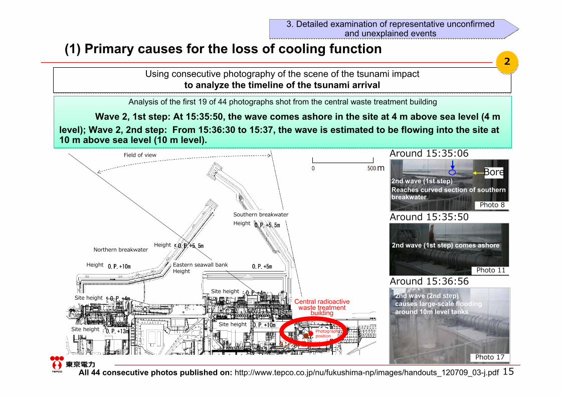
Analysis of the first 19 of 44 photographs shot from the central waste treatment building
Wave 2, 1st step: At 15:35:50, the wave comes ashore in the site at 4 m above sea level (4 m level); Wave 2, 2nd step: From 15:36:30 to 15:37, the wave is estimated to be flowing into the site at 10 m above sea level (10 m level).
All 44 consecutive photos published on: http://www.tepco.co.jp/nu/fukushima-np/images/handouts_120709_03-j.pdf
Central radioactive waste treatment
building
Bore
Photo 8
Photo 11
2nd wave (1st step) comes ashore
Around 15:35:06
Around 15:35:50
2nd wave (1st step)Reaches curved section of southern breakwater
2nd wave (2nd step)causes large-scale floodingaround 10m level tanks
Photo 17
Around 15:36:56
m
(1) Primary causes for the loss of cooling function
Field of view
Southern breakwaterHeight
Height
HeightNorthern breakwater
Eastern seawall bank Height
Photographyposition
Site height
Site height
Site height
Site height
3. Detailed examination of representative unconfirmedand unexplained events
3. Detailed examination of representative unconfirmedand unexplained events

16
Analysis of the timing of the consecutive photographyof the scene of the tsunami impact
Analysis of the timing of the consecutive photographyof the scene of the tsunami impact
33
We analyzed the time when tsunami wave 2 (1st step) struck and estimated that the camera's internal clock was fast by between 6 m 20 sec. to 6 m 41 sec. (Hereafter, photography times have been adjusted assuming a median value of 6 m 30 sec.)
The wave arrival times estimated here were obtained using an appropriate method and there are no significant discrepancies.
Curved section of southern breakwater
We analyzed the time when the 2nd wave (1st step) of the tsunami reached the curved section of southern breakwater and compared it with the photography time (internal clock) for photo8 (also shown on previous page).
(b) Time required for propagation85 to 106 sec.*
Appro
x. 1,0
00m
Wave gauge
(a) + (b) = Estimated time of arrival15:34:55 to 15:36:16
Photo 8
Com
parison
*: Calculated using the estimated wave velocity based on total water depth and still water depth
(a) Wave gauge elapsed time of
15:33:30
The wave arrives at the curved section
of the southern breakwater
Camera's internal time
15:41:36
(1) Primary causes for the loss of cooling function
3. Detailed examination of representative unconfirmedand unexplained events
3. Detailed examination of representative unconfirmedand unexplained events
17
Site elevation O.P. + 10 m
Site elevation O.P. + 4 m
Unit 1 Unit 2 Unit 3
Unit 4
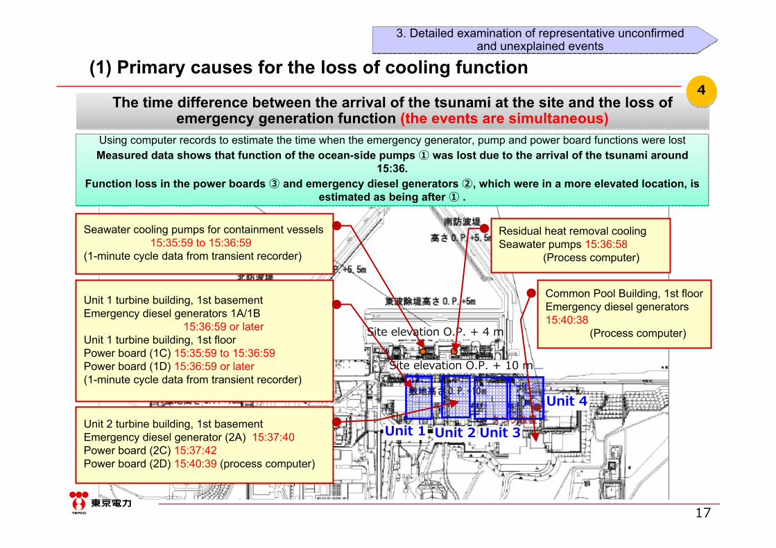
Residual heat removal coolingSeawater pumps 15:36:58
(Process computer)
Seawater cooling pumps for containment vessels15:35:59 to 15:36:59
(1-minute cycle data from transient recorder)
Common Pool Building, 1st floorEmergency diesel generators15:40:38
(Process computer)
Unit 1 turbine building, 1st basementEmergency diesel generators 1A/1B
15:36:59 or laterUnit 1 turbine building, 1st floorPower board (1C) 15:35:59 to 15:36:59Power board (1D) 15:36:59 or later(1-minute cycle data from transient recorder)
Unit 2 turbine building, 1st basementEmergency diesel generator (2A) 15:37:40Power board (2C) 15:37:42Power board (2D) 15:40:39 (process computer)
The time difference between the arrival of the tsunami at the site and the loss of emergency generation function (the events are simultaneous)
The time difference between the arrival of the tsunami at the site and the loss of emergency generation function (the events are simultaneous)
44
Using computer records to estimate the time when the emergency generator, pump and power board functions were lostMeasured data shows that function of the ocean-side pumps ① was lost due to the arrival of the tsunami around
15:36.Function loss in the power boards ③ and emergency diesel generators ②, which were in a more elevated location, is
estimated as being after ① .
(1) Primary causes for the loss of cooling function
3. Detailed examination of representative unconfirmedand unexplained events
3. Detailed examination of representative unconfirmedand unexplained events

18
The sequence of function loss in equipment within the site(function lost sequentially starting from the ocean side)
The sequence of function loss in equipment within the site(function lost sequentially starting from the ocean side)
55
Turbinebuilding
Reactor building
15:36 to 15:37
10 m level
0 m4 m level
From data gleaned from process computers and transient recorders, it is estimated that the effects of the tsunami progressed sequentially starting from the ocean side, as follows:
[15:36] Seawater pump function lost → Bus voltage (C) function lost →[Subsequently] function lost in bus voltage (D) and emergency diesel generators (A) and (B).
① Seawater pumps(A) to (D) ② Power board (C)
⑤ Emergency dieselgenerator (B)
③ Power board (D)
④ Emergency dieselgenerator (A)
(1) Primary causes for the loss of cooling function
3. Detailed examination of representative unconfirmedand unexplained events
3. Detailed examination of representative unconfirmedand unexplained events

19
with regard to the causes of flooding on the 4th floor of the Unit 1 reactor building when the earthquake struck, it is highly likely that water in the spent fuel pool entered the air-conditioning ducts due to agitation during the earthquake, and the flooding was from the overflow prevention chamber
with regard to the causes of flooding on the 4th floor of the Unit 1 reactor building when the earthquake struck, it is highly likely that water in the spent fuel pool entered the air-conditioning ducts due to agitation during the earthquake, and the flooding was from the overflow prevention chamber
-- Key study points aimed at verification and explanation --
By studying drawings,understanding which equipment/facilities may have been flooded
By studying drawings,understanding which equipment/facilities may have been flooded
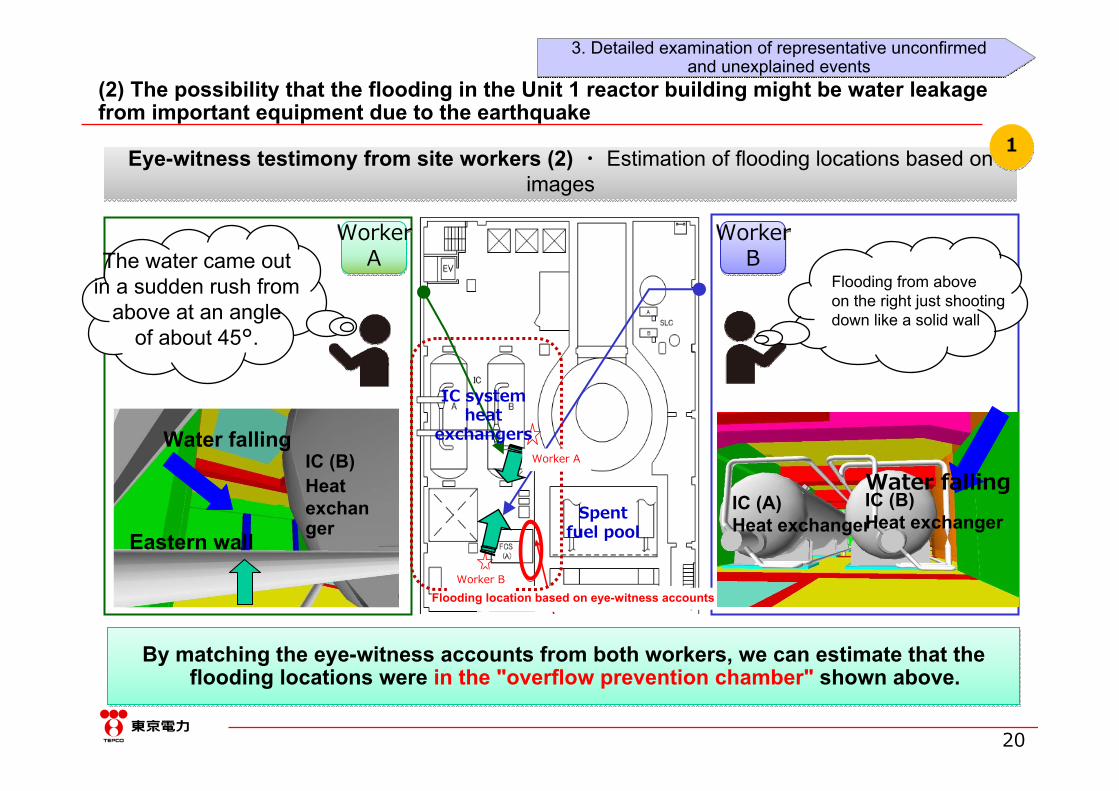
Eye-witness testimony from site workers (2) ・ Estimation of flooding locations based on images
Eye-witness testimony from site workers (2) ・ Estimation of flooding locations based on images
The Investigation Commission appointed by Diet indicated the possibility of water leakage from inside the reactor, but...
By checking water levels in the isolation condenser (IC) heat exchanger,confirming that there is no damage consistent with water discharge from inside
By checking water levels in the isolation condenser (IC) heat exchanger,confirming that there is no damage consistent with water discharge from inside
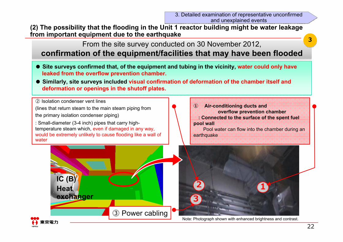
From the site survey conducted on 30 November 2012,confirmation of the equipment/facilities that may have been flooded
From the site survey conducted on 30 November 2012,confirmation of the equipment/facilities that may have been flooded
11
44
33
22
3. Typical details of the studies into unconfirmed and unexplained events(2) The possibility that the flooding in the Unit 1 reactor building might be water leakage from important equipment due to the earthquake
20
Eye-witness testimony from site workers (2) ・ Estimation of flooding locations based on images
Eye-witness testimony from site workers (2) ・ Estimation of flooding locations based on images
B氏
A氏
The water came outin a sudden rush from
above at an angleof about 45°.
Flooding from aboveon the right just shootingdown like a solid wall
目撃情報に基づく出水箇所
By matching the eye-witness accounts from both workers, we can estimate that the flooding locations were in the "overflow prevention chamber" shown above.
By matching the eye-witness accounts from both workers, we can estimate that the flooding locations were in the "overflow prevention chamber" shown above.
Flooding location based on eye-witness accounts
Water falling
Eastern wall
IC (B)Heat exchanger
WorkerA
WorkerA
WorkerB
WorkerB
Water fallingIC (B)Heat exchanger
IC (A)Heat exchanger
Spentfuel pool
IC system heat
exchangers
11
(2) The possibility that the flooding in the Unit 1 reactor building might be water leakage from important equipment due to the earthquake
Worker A
Worker B
3. Detailed examination of representative unconfirmedand unexplained events
3. Detailed examination of representative unconfirmedand unexplained events

21
By studying drawings,understanding which equipment/facilities may have been flooded
By studying drawings,understanding which equipment/facilities may have been flooded
22
● Studying the drawings made it clear that, apart from this overflow prevention chamber, there is no other equipment near the flooding location that could cause an overflow that accords with the eye-witness accounts (see previous page).
● The "Committee on Accident Analysis" of the Nuclear Regulation Authority (NRA) also studied the possibility of flooding from this chamber and concluded that it was highly likely that the flooding was from that location.
NEW
S
Unit 1 reactor building, 4th floor
Flooding location basedon eye-witness accounts
Air-conditioningductinlets
Spent fuel pool (SFP)handrail (reactor building
5th floor)
Spentfuel poolair-conditioning ducts
Overflow preventionchamber
Spentfuel poollocation
What is the "overflow prevention chamber"?The overflow prevention chamber is installed to prevent water overflowing from the spent fuel pool (SFP) from getting through the air-conditioning ducts and leaking out of the radiation controlled area by holding and then draining the overflow. To ensure that there is no risk at all of leakage into the air-conditioning ducts, the chamber was closed by a diaphragm to isolate the overflowprevention chamber from the duct downstream.
Overflow preventionchamber location
(2) The possibility that the flooding in the Unit 1 reactor building might be water leakage from important equipment due to the earthquake
3. Detailed examination of representative unconfirmedand unexplained events
3. Detailed examination of representative unconfirmedand unexplained events
22
IC (B)Heat exchanger
From the site survey conducted on 30 November 2012,confirmation of the equipment/facilities that may have been flooded
From the site survey conducted on 30 November 2012,confirmation of the equipment/facilities that may have been flooded
33
● Site surveys confirmed that, of the equipment and tubing in the vicinity, water could only have leaked from the overflow prevention chamber.
● Similarly, site surveys included visual confirmation of deformation of the chamber itself and deformation or openings in the shutoff plates.
● Site surveys confirmed that, of the equipment and tubing in the vicinity, water could only have leaked from the overflow prevention chamber.
● Similarly, site surveys included visual confirmation of deformation of the chamber itself and deformation or openings in the shutoff plates.
Note: Photograph shown with enhanced brightness and contrast.③ Power cabling
32 1
(2) The possibility that the flooding in the Unit 1 reactor building might be water leakage from important equipment due to the earthquake
① Air-conditioning ducts andoverflow prevention chamber
: Connected to the surface of the spent fuel pool wall
Pool water can flow into the chamber during an earthquake
② Isolation condenser vent lines(lines that return steam to the main steam piping fromthe primary isolation condenser piping): Small-diameter (3-4 inch) pipes that carry high-temperature steam which, even if damaged in any way, would be extremely unlikely to cause flooding like a wall of water
3. Detailed examination of representative unconfirmedand unexplained events
3. Detailed examination of representative unconfirmedand unexplained events

23
By checking water levels in the isolation condenser (IC) heat exchanger,confirming that there is no damage consistent with water discharge from inside
important equipment near the site
By checking water levels in the isolation condenser (IC) heat exchanger,confirming that there is no damage consistent with water discharge from inside
important equipment near the site
44
Hypothesis ①: The primary piping in the IC system or the vapor phase side of the IC tank was damaged
"Steam, not water, is generated" butThere was no confirmation of steam at the site.
Steam, not water, is generated
Hypothesis ②: The vapor phase side of the IC tank was damaged
"Large amounts of retained water are released" butThe site water level was checked on 18 October
2011A: 65%, B: 85%
A was used after the earthquake,so the level is considered to have dropped.
Large amounts of retained water were released
Level in A: 65%
Level in B: 85%
(2) The possibility that the flooding in the Unit 1 reactor building might be water leakage from important equipment due to the earthquake
●Because there is no confirmation of steam at the site and given that the amount of water remaining in the IC tank can be confirmed (65% in A and 85% in B), it is considered unlikely that any damage occurred that would cause an outflow of water inside important equipment near the site.
●Because there is no confirmation of steam at the site and given that the amount of water remaining in the IC tank can be confirmed (65% in A and 85% in B), it is considered unlikely that any damage occurred that would cause an outflow of water inside important equipment near the site.
Released to atmosphere
Isolation condenser BIsolation condenser A
Reactor pressure vessel
Reactor containment vesselFrom watersupply system
From fire protection system
Isolation condenser flow configuration
3. Detailed examination of representative unconfirmedand unexplained events
3. Detailed examination of representative unconfirmedand unexplained events

24
If all the water injected in from fire trucks had reached the reactor, it should have adequately cooled the reactor.
Some of the water may have flowed into other systems
If all the water injected in from fire trucks had reached the reactor, it should have adequately cooled the reactor.
Some of the water may have flowed into other systems
-- Key study points aimed at verification and explanation --
11
-- Utilizing the study results in the Kashiwazaki-Kariwa Nuclear Power Station --
Review locations where inflow is possibleUse alternative water injection means
to achieve effective water injection to the reactor
-- Future study points --
Assessment of the actual amount of water injected into the reactor and continued study into
its effect on the development of the accident
22
Information extremely important to assessing the accident development behavior is:The correlation between the amount of water injected into the building
by fire trucks and the amount of water necessary for coolingand
Identifying locations other than the reactor into which the injected water may have flowed
11
1-11-1
1-21-2
3. Typical details of the studies into unconfirmed and unexplained events
-- Key study points aimed at verification and explanation --
(3) Reasons why the reactor was not sufficiently cooled, despite water being injected in from fire trucks

25
In Units 1-3, the amount of water injected into the reactors by fire truckswas sufficient to replenish the water vaporized by the decay heat
In Units 1-3, the amount of water injected into the reactors by fire truckswas sufficient to replenish the water vaporized by the decay heat
Ascertaining the amount of water injected into the reactorby fire trucks and the amount of water necessary for cooling
Ascertaining the amount of water injected into the reactorby fire trucks and the amount of water necessary for cooling
1-11-1
0
25
50
75
100
3/11 12:00
3/12 0:00
3/12 12:00
3/13 0:00
3/13 12:00
3/14 0:00
3/14 12:00
3/15 0:00
3/15 12:00
3/16 0:00
3/16 12:00
注水
量(m
3/h)
海水(減圧前)
海水(減圧後)
必要注水量
Figure Unit 2 example: Correlation between the amount of water from fire trucks and the required amount
Injecting by fire trucks beginsWater injection using the Reactor Core Isolation Cooling
System (RCIC)
Assessment of the actual amount of water injected into the reactor and its effect on the development of the accident
-- Challenges requiring continued study in the future --
Estimated using the fire truck pump discharge
pressure gauge and flow meter
(3) Reasons why the reactor was not sufficiently cooled, despite water being injected in from fire trucks
Seawater (before pressure loss)Seawater (after pressure loss)Injected amount necessary
3. Detailed examination of representative unconfirmedand unexplained events
3. Detailed examination of representative unconfirmedand unexplained events
The amount of introduced water needed toreplenish the water vaporized by decay heat

26
Confirming that there are paths that generate bypass flows to the main condenser and condensate storage tank
Confirming that there are paths that generate bypass flows to the main condenser and condensate storage tank
Information extremely important to assessing the accident development behavior is:Ascertaining locations other than the reactor into which water from fire trucks might flow
Information extremely important to assessing the accident development behavior is:Ascertaining locations other than the reactor into which water from fire trucks might flow
1-21-2
In Unit 2, from the time water injecting by fire trucks began until
fuel rods were exposed and damaged
Late March 2011Confirmation of water accumulated
in the main condenser
Confirmation from piping drawings that there were paths that would
generate bypass flows to the main condenser and condensate storage
tank during the accident
Suggested possibility of bypass flows
for water from fire trucks
-- Background to the identification of possible locations --
Condensatestorage tank
ReactorPressurevessel
Condensatetransfer pump
Filtratetank
Fire-extinguishing pump
Fire-extinguishing system (FP system)
Condensatepump
Evaporator
Valve seal
Maincondenser
Reactor building Turbine building
Fire truck pump discharge pressure gauge and flow meter
Flow of water into the reactor Bypass flow pathMain paths generating bypass flows(example of Unit 1)
3. Detailed examination of representative unconfirmedand unexplained events
3. Detailed examination of representative unconfirmedand unexplained events
(3) Reasons why the reactor was not sufficiently cooled, despite water being injected in from fire trucks
Make-up Water Condensate System(MUWC system)

27
Countermeasures implemented in the Kashiwazaki-Kariwa Nuclear Power Station
Countermeasures implemented in the Kashiwazaki-Kariwa Nuclear Power Station
Reviewing locations where bypass flows are possibleImplementing measures to effectively inject water into the reactor using alternate water injection
methods
Reviewing locations where bypass flows are possibleImplementing measures to effectively inject water into the reactor using alternate water injection
methods
22
Flow of water injectedusing the condensatetransfer pump
Flow of water sprayedin by fire trucks
Fire truck
Condensatetransfer pump
Filtratetank
Fire-extinguishing pump
Main condenser
Low-pressure condensate pump
Fire-extinguishing system (FP)
Make-up Water Condensate System(MUWC)
MOWater seal line
To reactor
Condensate storage pool(CSP)
Unlike Fukushima
Daiichi, has acheck valve
Motorized valve addedTo prevent bypass flows,
valves requiring a closing operationand valves where closure is to be
confirmedclarified in the instructions
Training in operation & checking conducted
Addition of a motorized valve to prevent bypass
flows when the Make-up Water Condensate System
is used as an alternate water injection method
-- Utilization or application of study findings --
Provision of digital recorders anddedicated monitoring batteries forparameters such as the reactor
waterlevel and injection flow rate into the
reactor
ReactorPressure
vessel
3. Detailed examination of representative unconfirmedand unexplained events
3. Detailed examination of representative unconfirmedand unexplained events
(3) Reasons why the reactor was not sufficiently cooled, despite water being injected in from fire trucks
28
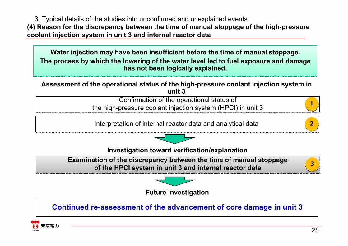
Water injection may have been insufficient before the time of manual stoppage.The process by which the lowering of the water level led to fuel exposure and damage
has not been logically explained.
Water injection may have been insufficient before the time of manual stoppage.The process by which the lowering of the water level led to fuel exposure and damage
has not been logically explained.
Assessment of the operational status of the high-pressure coolant injection system in unit 3
Examination of the discrepancy between the time of manual stoppageof the HPCI system in unit 3 and internal reactor data
Examination of the discrepancy between the time of manual stoppageof the HPCI system in unit 3 and internal reactor data
Confirmation of the operational status of the high-pressure coolant injection system (HPCI) in unit 3
Confirmation of the operational status of the high-pressure coolant injection system (HPCI) in unit 3
Interpretation of internal reactor data and analytical data Interpretation of internal reactor data and analytical data
Investigation toward verification/explanation
11
22
33
(4) Reason for the discrepancy between the time of manual stoppage of the high-pressure coolant injection system in unit 3 and internal reactor data
Future investigation
Continued re-assessment of the advancement of core damage in unit 3
3. Typical details of the studies into unconfirmed and unexplained events
29
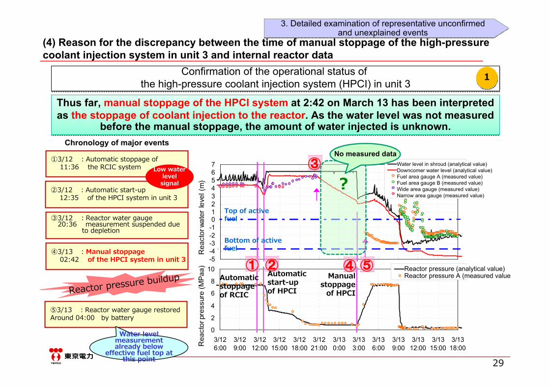
Thus far, manual stoppage of the HPCI system at 2:42 on March 13 has been interpreted as the stoppage of coolant injection to the reactor. As the water level was not measured
before the manual stoppage, the amount of water injected is unknown.
Thus far, manual stoppage of the HPCI system at 2:42 on March 13 has been interpreted as the stoppage of coolant injection to the reactor. As the water level was not measured
before the manual stoppage, the amount of water injected is unknown.
Confirmation of the operational status of the high-pressure coolant injection system (HPCI) in unit 3
Confirmation of the operational status of the high-pressure coolant injection system (HPCI) in unit 3 11
①3/12 :Automatic stoppage of11:36 the RCIC system
②3/12 :Automatic start-up 12:35 of the HPCI system in unit 3
③3/12 :Reactor water gauge20:36 measurement suspended due
to depletion
④3/13 :Manual stoppage02:42 of the HPCI system in unit 3
Reactor pressure buildup
⑤3/13 :Reactor water gauge restoredAround 04:00 by battery
Chronology of major events
-5-4-3-2-101234567
3/126:00
3/129:00
3/1212:00
3/1215:00
3/1218:00
3/1221:00
3/130:00
3/133:00
3/136:00
3/139:00
3/1312:00
3/1315:00
3/1318:00
原子
炉水
位 (m
)
シュラウド内水位(解析値)ダウンカマ水位(解析値)燃料域水位計A(測定値)燃料域水位計B(測定値)広帯域水位計(測定値)狭帯域水位計(測定値)
0
2
4
6
8
10
3/126:00
3/129:00
3/1212:00
3/1215:00
3/1218:00
3/1221:00
3/130:00
3/133:00
3/136:00
3/139:00
3/1312:00
3/1315:00
3/1318:00
原子
炉圧
力 (M
Paa
) 原子炉圧力(解析値)原子力圧力A(測定値)
① ② ④
③
⑤
Top of active fuel
Bottom of active fuel
?
Automatic start-up of HPCI
Manual stoppage
of HPCI Automatic stoppage of RCIC
No measured data
Water level measurement already below
effective fuel top at this point
(4) Reason for the discrepancy between the time of manual stoppage of the high-pressure coolant injection system in unit 3 and internal reactor data
Water level in shroud (analytical value)Downcomer water level (analytical value)Fuel area gauge A (measured value)Fuel area gauge B (measured value)Wide area gauge (measured value)Narrow area gauge (measured value)
Reactor pressure (analytical value)Reactor pressure A (measured value
Low water level
signal
3. Detailed examination of representative unconfirmedand unexplained events
3. Detailed examination of representative unconfirmedand unexplained events
30
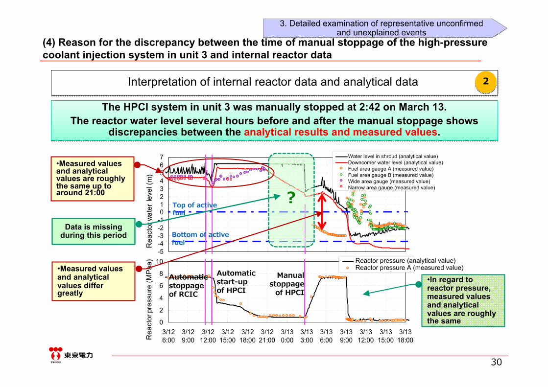
The HPCI system in unit 3 was manually stopped at 2:42 on March 13.The reactor water level several hours before and after the manual stoppage shows
discrepancies between the analytical results and measured values.
The HPCI system in unit 3 was manually stopped at 2:42 on March 13.The reactor water level several hours before and after the manual stoppage shows
discrepancies between the analytical results and measured values.
Interpretation of internal reactor data and analytical data Interpretation of internal reactor data and analytical data 22
-5-4-3-2-101234567
3/126:00
3/129:00
3/1212:00
3/1215:00
3/1218:00
3/1221:00
3/130:00
3/133:00
3/136:00
3/139:00
3/1312:00
3/1315:00
3/1318:00
原子
炉水
位 (m
)シュラウド内水位(解析値)ダウンカマ水位(解析値)燃料域水位計A(測定値)燃料域水位計B(測定値)広帯域水位計(測定値)狭帯域水位計(測定値)
0
2
4
6
8
10
3/126:00
3/129:00
3/1212:00
3/1215:00
3/1218:00
3/1221:00
3/130:00
3/133:00
3/136:00
3/139:00
3/1312:00
3/1315:00
3/1318:00
原子
炉圧
力 (M
Paa
) 原子炉圧力(解析値)原子力圧力A(測定値)
?
•In regard to reactor pressure, measured values and analytical values are roughly the same
(4) Reason for the discrepancy between the time of manual stoppage of the high-pressure coolant injection system in unit 3 and internal reactor data
Water level in shroud (analytical value)Downcomer water level (analytical value)Fuel area gauge A (measured value)Fuel area gauge B (measured value)Wide area gauge (measured value)Narrow area gauge (measured value)
Reactor pressure (analytical value)Reactor pressure A (measured value)Automatic
start-up of HPCI
Manual stoppage
of HPCI Automatic stoppage of RCIC
•Measured values and analytical values differ greatly
Data is missing during this period
•Measured values and analytical values are roughly the same up to around 21:00
Top of active fuel
Bottom of active fuel
3. Detailed examination of representative unconfirmedand unexplained events
3. Detailed examination of representative unconfirmedand unexplained events

31
Examination of the discrepancy between the time of manual stoppage of the HPCI system in unit 3 and internal reactor data
Examination of the discrepancy between the time of manual stoppage of the HPCI system in unit 3 and internal reactor data
The process through which fuel was exposed and damaged has not been logically explained due to uncertainties in the operational status (actual amount of water
injected) of the HPCI system, but the advancement of core damage in unit 3 will be re-assessed in the future based on the estimated result that water injection to the
reactor by the HPCI system was insufficient.
33
-5
-4
-3
-2
-1
0
1
2
3
4
5
6
7
3/126:00
3/129:00
3/1212:00
3/1215:00
3/1218:00
3/1221:00
3/130:00
3/133:00
3/136:00
3/139:00
3/1312:00
3/1315:00
3/1318:00
Date/Time
Rea
ctor
wat
er le
vel (
m)
Fuel range (A)Fuel range (B)Narrow rangeWide rangeWide range(corrected)Fuel range(corrected)Water level inside shroud(analysis)Downcomer water level(analysis)
Manual stoppage of HPCI 3/13 2:42
Automatic start-up of
HPCI3/12 12:35
Reac
tor w
ater
leve
l (m
) (in
refe
renc
e to
ef
fect
ive fu
el to
p)
It is likely that water was not sufficiently injected into the reactor by the
HPCI after reactor pressure decreased
Analytical water level (black line )According to MAAP analysis, the water level was higher than the effective fuel top until 9:00 on March 13
Measured water level(gray circles )The fuel area gauge indicated a water level lower than the effective fuel top at around 4:00 on March 13
The discrepancy between the analytical results and
measured values cannot be reasonably explained at
present
(4) Reason for the discrepancy between the time of manual stoppage of the high-pressure coolant injection system in unit 3 and internal reactor data
Water level in shroud (analytical value)Downcomer water level (analytical value)Fuel area gauge A (measured value)Fuel area gauge B (measured value)Wide area gauge (measured value)Narrow area gauge (measured value)
Top of active fuel
3. Detailed examination of representative unconfirmedand unexplained events
3. Detailed examination of representative unconfirmedand unexplained events
32
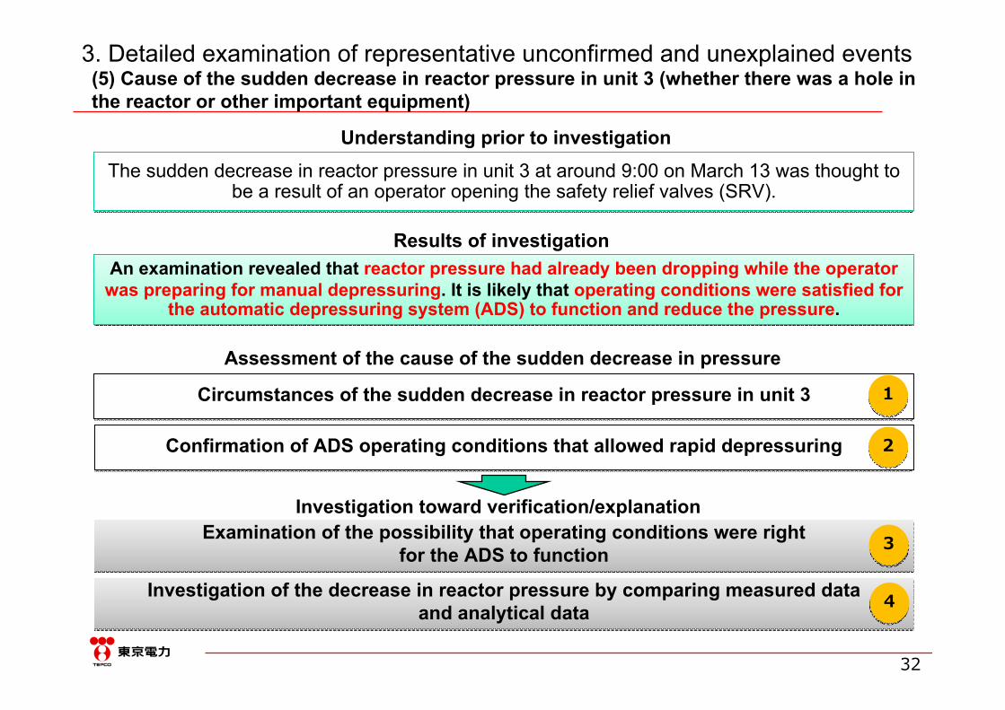
The sudden decrease in reactor pressure in unit 3 at around 9:00 on March 13 was thought to be a result of an operator opening the safety relief valves (SRV).
The sudden decrease in reactor pressure in unit 3 at around 9:00 on March 13 was thought to be a result of an operator opening the safety relief valves (SRV).
Assessment of the cause of the sudden decrease in pressure
Examination of the possibility that operating conditions were right for the ADS to function
Examination of the possibility that operating conditions were right for the ADS to function
Circumstances of the sudden decrease in reactor pressure in unit 3Circumstances of the sudden decrease in reactor pressure in unit 3
Investigation toward verification/explanation
11
33
(5) Cause of the sudden decrease in reactor pressure in unit 3 (whether there was a hole in the reactor or other important equipment)
Understanding prior to investigation
An examination revealed that reactor pressure had already been dropping while the operator was preparing for manual depressuring. It is likely that operating conditions were satisfied for
the automatic depressuring system (ADS) to function and reduce the pressure.
An examination revealed that reactor pressure had already been dropping while the operator was preparing for manual depressuring. It is likely that operating conditions were satisfied for
the automatic depressuring system (ADS) to function and reduce the pressure.
Results of investigation
Confirmation of ADS operating conditions that allowed rapid depressuringConfirmation of ADS operating conditions that allowed rapid depressuring 22
Investigation of the decrease in reactor pressure by comparing measured data and analytical data
Investigation of the decrease in reactor pressure by comparing measured data and analytical data 44
3. Detailed examination of representative unconfirmed and unexplained events

33
At around 9:00 on March 13, reactor pressure dropped while an operator was preparing for manual depressuring. Depressuring occurred rapidly within 2–3 minutes, while this normally takes around 20 minutes after manually opening the safety relief valves (SRV).
At around 9:00 on March 13, reactor pressure dropped while an operator was preparing for manual depressuring. Depressuring occurred rapidly within 2–3 minutes, while this normally takes around 20 minutes after manually opening the safety relief valves (SRV).
3/13 around 9:00Sudden decrease in pressure
Hour 3/132:00
Reactor pressure
2
8
10
原⼦
炉圧
⼒(M
Pa[g
age]
)
08:00 4:006:0010:0012:00 (AM)
3/13 2:42Manual stoppage of HPCI
Time
Approx. 7.3MPa↓
Approx. 0.5MPa
Circumstances of the sudden decrease in reactor pressure in unit 3Circumstances of the sudden decrease in reactor pressure in unit 3 11
(5) Cause of the sudden decrease in reactor pressure in unit 3 (whether there was a hole in the reactor or other important equipment)
3. Detailed examination of representative unconfirmedand unexplained events
3. Detailed examination of representative unconfirmedand unexplained events

34
It was understood that rapid depressuring is possible if the ADS functions, but it was thought that conditions were not right for the ADS in unit 3 to function.
It was understood that rapid depressuring is possible if the ADS functions, but it was thought that conditions were not right for the ADS in unit 3 to function.
Note) When pressure in the reactor is high and reactor water level cannot be maintained, ADS (automatic depressrizationsystem) opens the safety relief valves to lower the reactor pressure and allow water injection via a low-pressure water injection method. As one of the conditions for activating ADS, preparation of the low-pressure water injection system must be completed (pump discharge pressure must be established).
Fig. ADS starting conditions (logic diagram)D/W pressure (high)0.0137MPa[gage]
Reactor water level (low) L-1 +450mm from TAF
Reactor water level (low) nearL-3 + 4322mm from TAF
AND120 secTimeDelay
120 secTimeDelay
AND ADSfunctions
ADSfunctions
OR
Pump discharge pressure of the residual heat removal system0.344MPa[gage]Pump discharge pressure of thecore spray system0.689MPa[gage]
Loss of both
functions
ClearClear
ClearClear
ClearClear
ClearClear
NotClear
Logically speaking, ADS should not function
(*Logically, ADS should not function and perform rapid depressuring, but given the sudden decrease in pressure that actually occurred, the possibility of the ADS having functioned will be examined.)
Confirmation of ADS operating conditions that allowed rapid depressuring
Confirmation of ADS operating conditions that allowed rapid depressuring 22
These pumps could not operate due to blackout = Discharge pressure should not increase
(5) Cause of the sudden decrease in reactor pressure in unit 3 (whether there was a hole in the reactor or other important equipment)
3. Detailed examination of representative unconfirmedand unexplained events
3. Detailed examination of representative unconfirmedand unexplained events

35
Transmission of pressure
②
Due to an increase in pressure in the suppression chamber (S/C), the discharge pressure gauge measured the prescribed value even though the pump in the residual heat removal
system (RHR) had not functioned.This may have set the conditions for depressuring by the ADS.
Due to an increase in pressure in the suppression chamber (S/C), the discharge pressure gauge measured the prescribed value even though the pump in the residual heat removal
system (RHR) had not functioned.This may have set the conditions for depressuring by the ADS.
Residual heat removal (RHR) pump
Discharge pressure gauge
Suppression chamber
Heat exchanger
Transmission of pressure
Open
Reactor pressure
vessel
③②
①Increase in
pressure in the S/C to 0.455MPa[abs]
①
The pressure gauge detected a value exceeding the
0.344MPa[gage] condition for ADS
operation
③
Examination of the possibility that operating conditions were right for the ADS to function
Examination of the possibility that operating conditions were right for the ADS to function 33
(5) Cause of the sudden decrease in reactor pressure in unit 3 (whether there was a hole in the reactor or other important equipment)
3. Detailed examination of representative unconfirmedand unexplained events
3. Detailed examination of representative unconfirmedand unexplained events

36
08:38 08:42 08:47 08:51 08:55 09:00 09:04 09:080
1
2
3
4
5
6
7
8
9
Strip chart1SRV2SRVs4SRVs6SRVs6SRVs water level at BAF8SRVs
Time [day]
Pre
ssu
re [
MP
a]
原子
炉圧
力[M
Pa]
時間
チャートデータ(実測値)
(水位実測値程度(BAF))
When conditions for the functioning of ADS were analyzed with 6 safety relief valves (SRV) open and the water level near the fuel bottom as indicated by the measured value, the actual decrease in
reactor pressure could be reproduced for the most part, so the possibility that operating conditions were right for the ADS to function has been verified.
ADS signal
Investigation of the decrease in reactor pressure by comparing measured data and analytical data
Investigation of the decrease in reactor pressure by comparing measured data and analytical data 44
Safety relief valve (SRV): When reactor pressure increases abnormally, the safety relief valve releases steam to the suppression chamber automatically, or manually via the central control room, to protect the pressure vessel (the released steam is cooled by water in the suppression chamber and condensed). It also functions as an automatic depressuring system (ADS) for the emergency core cooling system (ECCS).
(5) Cause of the sudden decrease in reactor pressure in unit 3 (whether there was a hole in the reactor or other important equipment)
Time
Chart data (measured values)
(water level is assumed to be BAF)
3. Detailed examination of representative unconfirmedand unexplained events
3. Detailed examination of representative unconfirmedand unexplained events
37
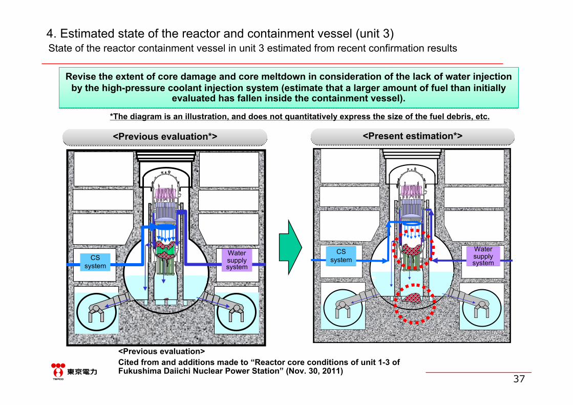
4. Estimated state of the reactor and containment vessel (unit 3)
Revise the extent of core damage and core meltdown in consideration of the lack of water injection by the high-pressure coolant injection system (estimate that a larger amount of fuel than initially
evaluated has fallen inside the containment vessel).
Revise the extent of core damage and core meltdown in consideration of the lack of water injection by the high-pressure coolant injection system (estimate that a larger amount of fuel than initially
evaluated has fallen inside the containment vessel).
State of the reactor containment vessel in unit 3 estimated from recent confirmation results
<Previous evaluation*><Previous evaluation*> <Present estimation*><Present estimation*>
給水系CS系CS
systemWater supply system
<Previous evaluation>Cited from and additions made to “Reactor core conditions of unit 1-3 of Fukushima Daiichi Nuclear Power Station” (Nov. 30, 2011)
*The diagram is an illustration, and does not quantitatively express the size of the fuel debris, etc.
CSsystem
Water supply system

38
5. Major issues for future examination
Of the 52 instances of unconfirmed and unexplained events extracted in this study, the following 10 issues will be given the highest priority for early clarification.
Of the 52 instances of unconfirmed and unexplained events extracted in this study, the following 10 issues will be given the highest priority for early clarification.
・ Examination of the operation of the safety relief valves after core damage
・ Discharge status of radioactive material since March 20
・ Enhancement of the accuracy of the amount of water injected into the reactor by fire trucks / Examination based on the conclusion of issue (3)
・ Evaluation of the operational status of the high-pressure coolant injection system (HPCI) in unit 3 and effect on the accident / Examination based on the conclusion of issue (4)
・ Dropping mechanism of the lower plenum of the melted core
・ Identification of the cause of the high-dose contamination of the Reactor Building Closed Cooling Water System (RCW) in unit 1
・ Increase in reactor pressure after forced depressuring in unit 2
・ Operation of the rupture disk in unit 2
・ Cause of the stoppage of the reactor core isolation cooling system (RCIC) in unit 3
・ Thermal stratification of the suppression pool in unit 3
Top Related