


Languages
Pages
Legal


Automation and controlEthernet TCP/IP andWeb technologiesNavigate freely across auniversal network
CatalogueJuly
04
Tra
nspa
rent
Rea
dy-
Eth
erne
tTC
P/IP
and
Web
tech
nolo
gies
04
ART. 802731 July 2004
MK
TE
D20
4073
ENSchneider Electric Industries SAS
Headquarters
89, bd Franklin RooseveltF - 92506 Rueil Malmaison Cedex
http://www.schneider-electric.comhttp://www.telemecanique.com
Owing to changes in standards and equipment, the characteristicsgiven in the text and images in this document are not binding us untilthey have been confirmed with us.
Production: Schneider Electric IndustriesPhotos: Schneider Electric IndustriesPrinted by: Pozzo Gros Monti - Italy

2
General contents 0 Transparent Ready
1 – PresentationIntroduction. . . . . . . . . . . . . . . . . . . . . . . . . . . . . . . . . . . . . . . . . . . . . . . . . page 1/2
Service classes offered . . . . . . . . . . . . . . . . . . . . . . . . . . . . . . . . . . . . . . . page 1/5
Panorama of Transparent Ready products . . . . . . . . . . . . . . . . . . . . . . .page 1/8
2 – System approachContents . . . . . . . . . . . . . . . . . . . . . . . . . . . . . . . . . . . . . . . . . . . . . . . . . . .page 2/1
Embedded Web servers, FactoryCast offer . . . . . . . . . . . . . . . . . . . . . . . page 2/2
Ethernet TCP/IP communication service . . . . . . . . . . . . . . . . . . . . . . . . page 2/12
Performances of Ethernet TCP/IP network . . . . . . . . . . . . . . . . . . . . . . page 2/24
Ethernet ConneXium wiring system . . . . . . . . . . . . . . . . . . . . . . . . . . . . page 2/24
System approach Application to electrical distribution . . . . . . . . . . . . . . . . . . . . . . . . . . . page 2/34Modicon Quantum Hot Standby . . . . . . . . . . . . . . . . . . . . . . . . . . . . . . page 2/36Unity Studio software suite. . . . . . . . . . . . . . . . . . . . . . . . . . . . . . . . . . page 2/37
Integration of Transparent Ready products. . . . . . . . . . . . . . . . . . . . . . page 2/40
3 – Field devicesContents . . . . . . . . . . . . . . . . . . . . . . . . . . . . . . . . . . . . . . . . . . . . . . . . . . .page 3/1
Modicon Momentum distributed I/O . . . . . . . . . . . . . . . . . . . . . . . . . . . . . page 3/2
Advantys STB distributed I/O . . . . . . . . . . . . . . . . . . . . . . . . . . . . . . . . . . page 3/3
Advantys OTB distributed I/O . . . . . . . . . . . . . . . . . . . . . . . . . . . . . . . . . . page 3/4
ATV 38/58 variable speed drives. . . . . . . . . . . . . . . . . . . . . . . . . . . . . . . . page 3/5
Inductel identification system . . . . . . . . . . . . . . . . . . . . . . . . . . . . . . . . . page 3/6
4 – Electrical Distribution productsContents . . . . . . . . . . . . . . . . . . . . . . . . . . . . . . . . . . . . . . . . . . . . . . . . . . .page 4/1
MV and LV protection and metering . . . . . . . . . . . . . . . . . . . . . . . . . . . . . page 4/2
Advanced electrical circuit monitors . . . . . . . . . . . . . . . . . . . . . . . . . . . . page 4/3
Electrical power management software . . . . . . . . . . . . . . . . . . . . . . . . . . page 4/4
5 – Controller and PLCsContents . . . . . . . . . . . . . . . . . . . . . . . . . . . . . . . . . . . . . . . . . . . . . . . . . . .page 5/1
Modicon Momentum M1E processor adapters . . . . . . . . . . . . . . . . . . . . page 5/2
Twido programmable controller . . . . . . . . . . . . . . . . . . . . . . . . . . . . . . . . page 5/3
Modicon TSX Micro platform. . . . . . . . . . . . . . . . . . . . . . . . . . . . . . . . . . . page 5/4
Modicon Premium/Atrium platform . . . . . . . . . . . . . . . . . . . . . . . . . . . . . page 5/5
Modicon Quantum platform. . . . . . . . . . . . . . . . . . . . . . . . . . . . . . . . . . . . page 5/8

3
6 – Humain/Machine Interface productsContents . . . . . . . . . . . . . . . . . . . . . . . . . . . . . . . . . . . . . . . . . . . . . . . . . . . page 6/1
Magelis XBT graphic terminals . . . . . . . . . . . . . . . . . . . . . . . . . . . . . . . . page 6/2
Magelis iPC industrial PCs . . . . . . . . . . . . . . . . . . . . . . . . . . . . . . . . . . . . page 6/3
FactoryCast HMI application development software . . . . . . . . . . . . . . . page 6/5
Vijeo Look supervisory software . . . . . . . . . . . . . . . . . . . . . . . . . . . . . . . page 6/6
Monitor Pro supervisory software . . . . . . . . . . . . . . . . . . . . . . . . . . . . . . page 6/7
OFS data server software . . . . . . . . . . . . . . . . . . . . . . . . . . . . . . . . . . . . . page 6/8
7 – Cabling systemContents . . . . . . . . . . . . . . . . . . . . . . . . . . . . . . . . . . . . . . . . . . . . . . . . . . . page 7/1
ConneXium hubs . . . . . . . . . . . . . . . . . . . . . . . . . . . . . . . . . . . . . . . . . . . . page 7/2
ConneXium transceivers . . . . . . . . . . . . . . . . . . . . . . . . . . . . . . . . . . . . . page 7/3
ConneXium switches . . . . . . . . . . . . . . . . . . . . . . . . . . . . . . . . . . . . . . . . page 7/4
ConneXium gateways . . . . . . . . . . . . . . . . . . . . . . . . . . . . . . . . . . . . . . . . page 7/6
Connection cables . . . . . . . . . . . . . . . . . . . . . . . . . . . . . . . . . . . . . . . . . . page 7/7
8 – Modbus-IDA organisation and Collaborative Automation Partner ProgramSommaire . . . . . . . . . . . . . . . . . . . . . . . . . . . . . . . . . . . . . . . . . . . . . . . . . . page 8/1
Modus-IDA organisation . . . . . . . . . . . . . . . . . . . . . . . . . . . . . . . . . . . . . . page 8/2
Collaborative Automation Partner Program presentation. . . . . . . . . . . page 8/3
Examples of partner offerProsoft Technology . . . . . . . . . . . . . . . . . . . . . . . . . . . . . . . . . . . . . . . . page 8/4ConnectBlue . . . . . . . . . . . . . . . . . . . . . . . . . . . . . . . . . . . . . . . . . . . . . page 8/6ACKSYS . . . . . . . . . . . . . . . . . . . . . . . . . . . . . . . . . . . . . . . . . . . . . . . . page 8/7DATA-LINC Group . . . . . . . . . . . . . . . . . . . . . . . . . . . . . . . . . . . . . . . . page 8/8Senside . . . . . . . . . . . . . . . . . . . . . . . . . . . . . . . . . . . . . . . . . . . . . . . . . page 8/9
9 – ServicesSommaire . . . . . . . . . . . . . . . . . . . . . . . . . . . . . . . . . . . . . . . . . . . . . . . . . . page 9/1
Transparent Ready product certifications . . . . . . . . . . . . . . . . . . . . . . . page 9/2
Schneider Electric worldwide . . . . . . . . . . . . . . . . . . . . . . . . . . . . . . . . . page 9/4
Index . . . . . . . . . . . . . . . . . . . . . . . . . . . . . . . . . . . . . . . . . . . . . . . . . . . . . page 9/11

1

1/1
1
Contents 1 - Presentation 0
1 - Presentation
b Introduction . . . . . . . . . . . . . . . . . . . . . . . . . . . . . . . . . . . . . . . . . . . . . . . page 1/2
b Service classes offered . . . . . . . . . . . . . . . . . . . . . . . . . . . . . . . . . . . . . . page 1/5
Panorama of Transparent Ready products. . . . . . . . . . . . . . . . . . . . . . . page 1/8
1/2
1
Presentation Transparent Ready 0
Universal technologies for a world withoutrestrictions
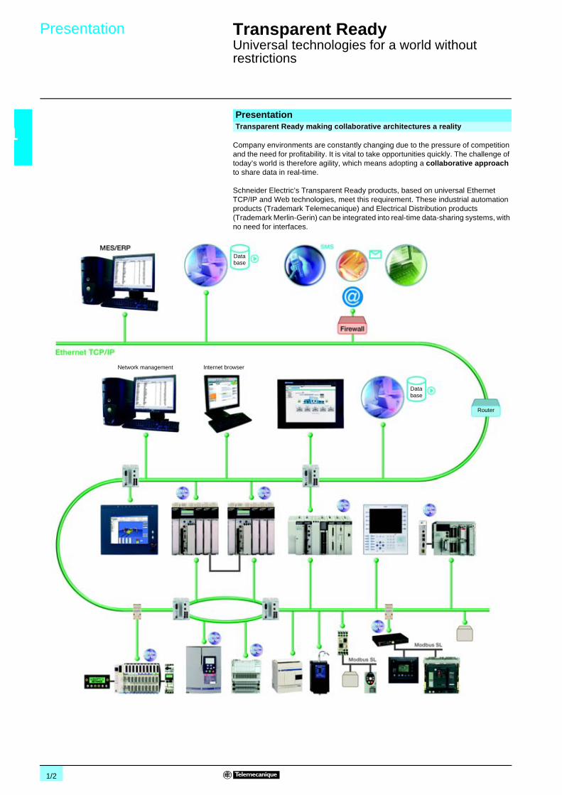
Company environments are constantly changing due to the pressure of competitionand the need for profitability. It is vital to take opportunities quickly. The challenge oftoday’s world is therefore agility, which means adopting a collaborative approachto share data in real-time.
Schneider Electric’s Transparent Ready products, based on universal EthernetTCP/IP and Web technologies, meet this requirement. These industrial automationproducts (Trademark Telemecanique) and Electrical Distribution products(Trademark Merlin-Gerin) can be integrated into real-time data-sharing systems, withno need for interfaces.
PresentationTransparent Ready making collaborative architectures a reality
Database
Database
Network management Internet browser
Router

1/3
1
Presentation (continued) Transparent Ready 0
Universal technologies for a world withoutrestrictions
The recognition of Ethernet TCP/IP, both in organizations and on the Internet, hasmade it the communication standard of today. Its wide use is leading to a reductionin connection costs, increased performance and the addition of new functions, whichall combine to ensure its durability.
Ethernet TCP/IP meets the connection requirements of every application:b Twisted pair copper cables for simplicity and low cost.b Optical fiber for immunity to interference and for long distances.b Communication redundancy, inherent in the IP protocol.b Radio or satellite to overcome wiring restrictions.b Remote point-to-point access via the telephone network or the Internet for the costof a local call.
Ethernet TCP/IP, a truly open technology, supports all types of communication:v Web pagesv File transferv Industrial messaging, etcWith its high speed, the network no longer limts the performance of the application.The architecture can evolve without any difficulty. The products remain compatible,ensuring the long-term durability of the system.
Modbus has been the de facto standard for serial link protocols in industry since1979. It is used for the communication of millions of automation devices. As a resultof this success, the Internet community has reserved the TCP 502 port for Modbus.Modbus can thus be used for exchanging automation data on both Ethernet TCP/IPand the Internet, as well as for all other applications (file exchange, Web pages,e-mail, etc).The simple structure of Modbus is bringing it ever-increasing success. Users candownload the specifications and source code for numerous products that use theModbus/TCP protocol, free of charge from the Modbus-IDA websitewww.modbus-ida.org.Building on its industrial expertise, Telemecanique now has a complete offer of highlyuser-friendly services on Ethernet TCP/IP that are dedicated to the world ofautomation: Modbus TCP messaging, optimized I/O Scanning, publication andsubscription of variables between Controllers and PLCs (Global Data), automaticproduct reconfiguration (Faulty Device Replacement), pass band monitoring, systemdiagnostics (Web), etc.The single network, requiring no interfaces between the worlds of informationtechnology and automation, is now a reality.
Presentation (continued)The universal communication standard: Ethernet TCP/IP
Modbus messaging: a standard technology adapted for the world ofautomation

1/4
1
Presentation (continued) Transparent Ready 0
Universal technologies for a world withoutrestrictions
Schneider Electric broke new ground in 1998 with the first Web servers embeddedin automation products. These servers provide remote access, using a simpleInternet browser, to process information and equipment diagnostics.
With FactoryCast HMI, Telemecanique was once again the first, making the Webservers in Controllers and PLCs “active”. Not only does the Web server providepages containing the system and process variables, but it also executes tasks totallyautonomously, without making use of the PLC processor: management of a real-timeHMI database, e-mail transmission, calculations, connectivity with databases, etc.
With its functions embedded in a PLC, the FactoryCast HMI active Web server:b Simplifies or removes the need for conventional HMI/SCADA (Supervision ControlAnd Data Acquisition) solutions, reducing communication via polling to updateHMI/SCADA databases.b Provides remote multistation “nomadic” control, without any special software onthe client stations.b Provides a direct link to a company’s information systems, without the need for aninterface.
Telemecanique has a wide range of Transparent Ready products: Controllers andPLCs, industrial PCs, HMI devices, variable speed drives, I/O modules, gateways,servers, switches, SCADA software, inductive identification systems, etc.
These products provide different levels of Web services and communication serviceson Ethernet TCP/IP, according to users’ requirements. In order to simplify choice andensure their interoperability within a system, each Transparent Ready product is nowidentified by the class of services it provides.
With Transparent Ready you can:
Presentation (continued)Free navigation on the Web Automation
Transparent Ready for a world without restrictions
Are you Transparent Ready?
Use V a common Ethernet TCP/IP infrastructure, covering all levels, from automationto company management.
Benefit V from the competitive advantages of proven high performance levels.
Reduce V downtime thanks to remote diagnostics via the Web.
Create V secure connections throughout the world.
Minimize V training costs by using tools everyone is familiar with (Internet browser, etc).
Control V costs by using open universal standards that do not require any specialinterfaces.

1/5
1
Description Transparent Ready 0
Service classes offered
The Transparent Ready service classes make it possible to identify the servicesprovided by each product:b Diagnostic, display and control services via Web technologiesb Ethernet communication services
The Transparent Ready service classes thus simplify the choice of products andensure their interoperability within an architecture.
The service level of a Web server is defined by 4 service classes identified by a letter:b Class A: No Web serviceb Class B: Standard Web servicesb Class C: Configurable Web servicesb Class D: Active Web services
Transparent Ready products with an embedded Web server can provide 4 types ofWeb service:b Maintenance Web servicesb Control Web servicesb Diagnostic Web servicesb Optional Web services such as documentation or configuration
The following table specifies the services provided by each Web service class (A, B,C or D).
Presentation
Transparent Ready
Ethernettechnologies and
services
Web technologiesand services
Web service classes
Web server class
Maintenance Control Diagnostics Optional
Web services
ActiveWeb server
ConfigurableWeb server
StandardWeb server
No Webserver
D
C
B
A
- User website update
- Remote product softwareupdate- Remote auto-tests
- Product description
- No Web service
- Autonomous execution ofspecific services (forexample, e-mailtransmission, datatransmission, calculations,etc)
- PLC variables editor- Remote commands- User Web pages
- User-defined states
- Communication servicediagnostics- State of internal productresources
- Product status
- User documentation
- Configuration of networkparameters and Ethernetcommunication services- Product documentation

1/6
1
Description (continued) Transparent Ready 0
Service classes offered
The Ethernet communication services provided by a product are defined by 3 classes,identified by a number:b Class 10: standard Ethernet communication servicesb Class 20: Ethernet communication management services (network level andproduct level)b Class 30: advanced Ethernet communication services
Transparent Ready products can provide eight types of Ethernet communicationservice:b Modbus TCP messaging serviceb I/O Scanning serviceb FDR (Faulty Device Replacement) serviceb Network management service SNMPb Global Data serviceb Pass band management serviceb Time synchronization service NTPb (E-mail) event notification service, SMTP
These Ethernet communication services are described in chapter 2, “Systemapproach”, see pages 2/12 to 2/23.
The following table specifies the services provided for each Ethernet communicationservice class.
Ethernet communication service classes
Ethernetcommunicationservice classes
30
20
10
Ethernet communication services
Modbusmessaging
I/OScanning
FDR Networkmanagement
SNMP
GlobalData
Bandwidthmanagement
Timesynchroni-zation NTP
Advancedservices
Communicationmanagementservices
Standardservices
- Directreading/writingof I/O
- Periodicreading/writingof I/O
- Configurationof the list ofproductsscanned
- Use of theMIB library byan SNMPmanager
- Automaticcontrol andupdating of theproductparametersconfiguration
- Automaticassignment ofthe IP addressand networkparameters- Control andupdating of theconfigurationand productparameters bythe user
- Localassignment ofthe IP addressVerification ofduplicate IPaddresses
- Monitoring ofload level
-Synchroniza-tion of productclocks
- Publicationandsubscriptionof networkvariables
- Reading/writing of datawords
- Detection ofproducts byan SNMPmanager
E-mailSMTP
- Notificationof events bye-mail

1/7
1
Description (continued) Transparent Ready 0
Service classes offered
The services provided by a Transparent Ready product are identified by a letterdefining the level of Web service, followed by a number defining the level of Ethernetcommunication service. For example:b A class A10 product is a product with no Web service and standard Ethernetservices.b A class C30 product is a product with a configurable Web server and advancedEthernet communication services.
The services provided by a higher class include all the services supported bya lower class.
Transparent Ready products are chosen from 4 main families:b Sensor and preactuator type field products (simple or intelligent)b Controllers and PLCsb Human Machine Interface (HMI) applicationsb Dedicated gateways and servers
The selection table on the following pages can be used for choosing TransparentReady products according to the required service classes.
Choice of Transparent Ready products
Class 30
Simple and intelligentproducts
Class A Class B Class C Class D
A10
B20
B30
Class 20Controllers and PLCs
D10
C20
Class 10
Sta
ndar
dse
rvic
esC
omm
unic
atio
nm
anag
emen
tse
rvic
es
Adv
ance
dse
rvic
e
B10
No service Standard Configurable Active
Web services
Ethernetcommunication
services

1/8
1
Selection Transparent Ready 0
Product selection
Ethernet TCP/IP communicationservices
Webservices
No Web serverClass ANo Web service
Advanced servicesClass 30
v FDR (productreplacement),automatic checking ofnetwork parameters
v SNMP (networkadministration), use ofthe MIB library by anSNMP tool
v Global Datav Pass band
managementv NTP (clock
synchronization)v SMTP (e-mail
notification)
CommunicationmanagementservicesClass 20
v Modbus TCPmessaging (read/writeI/O)
v I/O Scanningv FDR (product
replacement),automatic assignmentof network parameters
v SNMP (networkadministration),product detection
StandardcommunicationservicesClass 10
v Modbus TCPmessaging
v FDR (productreplacement),verification of duplicateIP address
Premium module TSX ETY 110Twido compact base TWD LCAE 40DRFMomentum adapter 170 ENT 110 02Advantys OTB interface OTB 1E0 DM9LPOsitrack station XGK S1715503Atrium coprocessor TSX PCI 57 204/454M
Human-MachineInterfaceproducts andsoftware
Graphic terminalsSee page 6/2
Magelis XBT G2p30/4330/5p30/6330Magelis XBT F024610/034610
iPC industrial PCsSee pages 6/3 and 6/4
Magelis Smart iPC MPC ST5 2NDJ 00T
Magelis Compact iPC MPC KT5 pNAA 00pMagelis Modular iPC MPC pN0 pNDp 00N
FactoryCast HMIdevelopment softwareSee page 5/7
FactoryCast HMI TLX CD FCHMI V1M
Control and supervisorysoftwareSee pages 6/5 to 6/7
Vijeo Look control VJL SMD BTp/RTp V25MMonitor Pro supervisory MP72 ppppOFS data server TLX CD ppOFS 30M
TSX ETY TSX P57
140 NOE 140 CPU
TSX ETZ
170 ENT
STB NIP
TWD LCAE
170 ENT
OTB 1E0
TSX PCIXGKS
EGX
XBT G
MPC ST5
1/9
1
0
Seepage
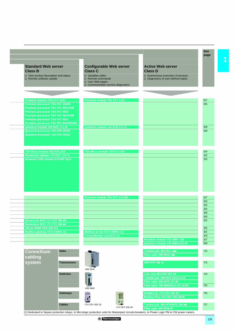
Standard Web serverClass B
Configurable Web serverClass C
Active Web serverClass D
v View product description and statusv Remote software update
v Variables editorv Remote commandsv User Web pagesv Communication service diagnostics
v Autonomous execution of servicesv Diagnostics of user-defined states
Premium module TSX ETY 4103 Premium module TSX ETY 5103 5/7
Premium processor TSX P57 1634M 5/5
Premium processor TSX P57 2623/34MPremium processor TSX P57 2823Premium processor TSX P57 3623/34MPremium processor TSX P57 4823Premium processor TSX P57 4634/5634MQuantum module 140 NOE 171 01 Quantum module 140 NOE 171 11 5/9
Quantum processor 140 CPU 65150 5/8
Quantum processor 140 CPU 65160
TSX Micro module TSX ETZ 410 TSX Micro module TSX ETZ 510 5/4Momentum adapter 170 ENT 110 01 3/2
Advantys STB module STB NIP 2212 3/3
Premium module TSX ETY 110 WS 5/75/3
3/2
3/4
3/6
5/6
Momentum M1E 171 CCC 980 p0 5/2Momentum M1E 171 CCC 960 p0Altivar 38/58 VW3 A58 310 3/5
Modbus gateway EGX 200MG (1) Modbus server EGX 400MG (1) 4/2
Circuit Monitor card ECC 21 4/3
Premium module TSX WMY 100 5/7
Quantum module 140 NWM 100 00 5/9
ConneXiumcablingsystem
Hubs Twisted pair 499 NEH 1pp 7/2
Fiber optic 499 NOH 1pp
Transceivers 499 NTR 10p p0 7/3
Switches Low cost 499 NES 251 00 7/4
Twisted pair 499 NES 181/271 00Fiber optic 499 NOS 171 00Fiber optic 499 NMS/NSS 251 01/02 7/5
Gateways Modbus SL 174 CEV 300 20 7/6
Modbus Plus 174 CEV 200 30/40
Cables Twisted pair 490 NTW/NTC 000 pp 7/7
Fiber optic 490 NOp 05(1) Dedicated to Sepam protection relays, to Micrologic protection units for Masterpact circuits-breakers, to Power Logic PM et CM power meters.
499 NOH
499 NMS
174 CEV 300 20174 CEV 200 40

2

2/1
2
Contents 2 - System approach 0
2.1 Embedded Web serversb FactoryCast presentation . . . . . . . . . . . . . . . . . . . . . . . . . . . . . . . . . . . . page 2/2
b Standard Web services . . . . . . . . . . . . . . . . . . . . . . . . . . . . . . . . . . . . . page 2/4
b FactoryCast Web server . . . . . . . . . . . . . . . . . . . . . . . . . . . . . . . . . . . . page 2/6
b FactoryCast HMI Web server . . . . . . . . . . . . . . . . . . . . . . . . . . . . . . . . . page 2/8
2.2 Ethernet TCP/IP communication serviceb Standard Ethernet services . . . . . . . . . . . . . . . . . . . . . . . . . . . . . . . . . page 2/12
b Modbus communication standard . . . . . . . . . . . . . . . . . . . . . . . . . . . . . page 2/15
b I/O Scanning service . . . . . . . . . . . . . . . . . . . . . . . . . . . . . . . . . . . . . . page 2/16
b FDR replacement service for faulty devices . . . . . . . . . . . . . . . . . . . . . page 2/17
b Global Data service in real time between stations . . . . . . . . . . . . . . . . page 2/18
b NTP time synchronization service . . . . . . . . . . . . . . . . . . . . . . . . . . . . page 2/19
b SMTP electronic mail notification service . . . . . . . . . . . . . . . . . . . . . . . page 2/20
b SNMP network management protocol service . . . . . . . . . . . . . . . . . . . page 2/21
b TCP Open optional service . . . . . . . . . . . . . . . . . . . . . . . . . . . . . . . . . . page 2/22
2.3 Performance of Ethernet TCP/IP networkb Processing capacity in terms of volume of exchanges . . . . . . . . . . . . . page 2/24
b Application response time . . . . . . . . . . . . . . . . . . . . . . . . . . . . . . . . . . page 2/26
2.4 Ethernet ConneXium wiring systemb Architectures in a same collision domain (hubs and transceivers) . . . . page 2/28
b Architectures with several collision domains (switches) . . . . . . . . . . . . page 2/32
b Redundancy . . . . . . . . . . . . . . . . . . . . . . . . . . . . . . . . . . . . . . . . . . . . . page 2/33
2.5 System approachb Application to electrical distribution . . . . . . . . . . . . . . . . . . . . . . . . . . . page 2/34
b Modicon Quantum Hot Standby on Ethernet TCP/IP . . . . . . . . . . . . . . page 2/36
b Unity Studio software suite . . . . . . . . . . . . . . . . . . . . . . . . . . . . . . . . . . page 2/37
2.6 Integration of Transparent Ready productsb Company level . . . . . . . . . . . . . . . . . . . . . . . . . . . . . . . . . . . . . . . . . . . page 2/40
b Inter-PLC level . . . . . . . . . . . . . . . . . . . . . . . . . . . . . . . . . . . . . . . . . . . page 2/41
b Field level . . . . . . . . . . . . . . . . . . . . . . . . . . . . . . . . . . . . . . . . . . . . . . . page 2/42
b Remote communication (Internet, telephone, radio) . . . . . . . . . . . . . . page 2/43
b Other requirements (diagnostic, interoperability, security). . . . . . . . . . . page 2/44

2/2
2
2.1
Presentation Transparent Ready 0
System approachEmbedded Web servers
In line with the Transparent Ready approach, TSX Micro, Premium, Quantum,Momentum, Advantys STB distributed I/O and ATV drive automation platformsprovide transparent access to data in realtime using Web-based technologies viatheir Ethernet TCP/IP or FactoryCast communication module.
The Transparent Ready communication modules in automation platforms integrateEthernet TCP/IP services (Modbus TCP/IP messaging, SNMP network managementfunctions, etc.) and provide the following Web functions:b Standard Web serverb FactoryCast Web serverb FactoryCast HMI Web service
Standard Web services can be used to execute diagnostic and maintenancefunctions on automation system installations locally or remotely using a simpleInternet browser:b PLC system and I/O module diagnostics, PLC error display (“Rack Viewer” pagesready to use)b Display and adjustment of PLC variables (“Data Editor” pages ready to use)
The embedded Web server is a realtime PLC data server. All the data can bepresented in the form of standard Web pages in HTML format and can therefore beaccessed using any Internet browser that supports the integrated Java code. Thestandard functions provided by the Web server are supplied “ready to use” andtherefore do not require any programming at either PLC level or at the level of thePC device supporting the Internet browser.
In addition to providing standard Web services, the FactoryCast Web server can beused to control and monitor automation system installations both locally andremotely. The following functions are available:b Management of system alarms and PLC application with partial or globalacknowledgment (“ready to use” pages for the “Alarm Viewer” function)b Application graphics diagnostics (customized graphical views created by the userusing the “Graphic Data Editor” function)b Graphics control via animated Web pages created by the user and stored in theFactoryCast module
FactoryCast Web servers can also be used to customize control, diagnostics andmaintenance interfaces via user-defined Web pages and Web pages transferred tothe module using FactoryCast configuration software (maximum available memoryrequired is 8 Mb).
In addition to the FactoryCast Web functions, the FactoryCast HMI Web serverprovides HMI Web functions, which are executed in the module itself:b Realtime HMI database management, independent of the PLC processorb Arithmetic and logical calculations based on HMI datab Connectivity with relational databasesb Transmission of electronic messages (e-mail)
FactoryCast HMI is an active Web server, which can be used to execute HMIfunctions integrated in a PLC module. This eliminates the need for communicationvia polling to update the HMI/SCADA database.In FactoryCast HMI modules, the HMI functions are executed without affecting thePLC application program and therefore the cycle time.
Presentation
Standard Web server
FactoryCast Web server
FactoryCast HMI Web server user
Ethernet TCP/IP PLC module services
Standard Web server
FactoryCast Web server
FactoryCast HMI Web server

2/3
2
2.1
Selection Transparent Ready 0
System approachEmbedded Web servers
FactoryCast is a range of PLC modules associated with their configuration softwareand combines the following features:b Realtime communication functions based on Ethernet TCP/IPb Predefined Web pages, which enable advanced installation diagnosticsb The capacity to store dynamic user-defined Web pages
(1) Electrical Distribution products of Merlin Gerin, see pages 4/2 to 4/4.
Selection of Telemecanique Transparent Ready modules (1)Products Reference Web server integrated
StandardClass B20
FactoryCastClass C20/C30
FactoryCast HMIClass D10
Quantum automationplatform
Processors 140 CPU 651 50
140 CPU 651 60
Modules 140 NOE 771 01
140 NOE 771 11
140 NWM 100 00
Premium automationplatform
Processors TSX P57 2623 M
TSX P57 2823 M
TSX P57 3623 M
TSX P57 4823 M
TSX P57 1634 M
TSX P57 2634 M
TSX P57 3634 M
TSX P57 4634 M
TSX P57 5634 M
Modules TSX ETY 4103
TSX ETY 110WS
TSX ETY 5103
TSX WMY 100
TSX Micro automationplatform
Modules TSX ETZ 410
TSX ETZ 510
Momentum automationplatform
M1Eprocessors
171 CCC 960 20
171 CCC 960 30
171 CCC 980 20
171 CCC 980 30
Modules 170 ENT 110 01
170 ENT 110 02
Advantys STBdistributed I/O
Networkinterfacemodule
STB NIP 2212
Altivar ATV 38/58variable speed drive
Card VW3 A58310

2/4
2
2.1
Functions Transparent Ready 0
System approachEmbedded Web servers, standard Web services
"Rack Viewer" and "Data Editor" functions are supported by the Ethernet TCP/IPmodules of the following:b TSX Micro platformb Premium platformb Quantum platformb Momentum platformb Advantys STB distributed I/Osb FactoryCast modulesSee module reference on page 2/3.
These functions can be accessed using a standard Internet browser connected to thenetwork. They are "ready to use" and secure (password-protected).
They can be used locally or remotely via:b Intranetb A modem and RAS serverb Internet.
Standard Web services
Internet
Firewall
Intranet
Remote Web clients
"Thin Client" PCWeb client
Premium + Web server
Quantum + Web server
TSX Micro + Web server
"Thin Client" Web client
MagelisSmart iPC

2/5
2
2.1
Functions (continued) Transparent Ready 0
System approachEmbedded Web servers, standard Web services
The "Rack Viewer" function (PLC rack display) can be used for PLC system and I/Odiagnostics. It displays the following in realtime:
b LED status on the front panel of the PLCb The PLC versionb The hardware configuration of the PLC including the status of the system bits andwordsb Detailed diagnostics of all I/O module channels or application-specific channels inthe configuration
The "Data Editor" function can be used to create tables of animated variables forrealtime read/write access to lists of PLC data.
The variables to be displayed can be entered and displayed either symbolically(S_Pump 234) or by their address (%MW99).
These variables only support write access if this option has been enabled using theFactoryCast configuration software. A second password must be entered andverified when writing a value to a variable.
Various animation tables containing specific application variables to be monitored ormodified can be created by the user and saved in the Ethernet TCP/IP module.
"Rack Viewer" PLC diagnostics function
Quantum hardware configuration
Premium main rack hardware configuration
"Data Editor" read/write function for PLC data and variables
Variables table

2/6
2
2.1
Functions Transparent Ready 0
System approachEmbedded Web servers, FactoryCast Web server
In addition to standard Web services, FactoryCast modules (see selection table onpage 2/3) support the following functions:b Alarm Viewerb Creation and display of graphical views via an online graphics editor (Graphic DataEditor supplied)b Hosting and display of Web pages created by the user
FactoryCast configuration software (supplied with FactoryCast modules) is requiredfor the last 2 functions.
"Alarm Viewer" is a ready-to-use password-protected function. Based on thediagnostics buffer managed in the PLCs (specific memory area used to store alldiagnostic events), this function is available with the Premium/Atrium platforms (withPL7 or Unity software) and the Quantum platform (with Unity software).
This function can be used to process alarms (display, acknowledgment and deletion)managed at PLC level by the system or using diagnostic function blocks known asDFBs (system-specific diagnostic function blocks and application-specific diagnosticfunction blocks created by the user).
The diagnostics viewer is a Web page comprising a list of messages, which displaysthe following information for each alarm:b Its stateb The type of associated diagnostic function block (DFB)b Its geographical areab The dates and times of the occurrence/removal of a fault.
FactoryCast Web server
Intranet
Internet
Remote Web client
Firewall
Premium + Web serverQuantum + Web server
TSX Micro + Web server
Modem+RAS server
“Thin Client” Web client
MagelisSmart iPC
Alarm Viewer function
Alarm Viewer page

2/7
2
2.1
Functions (continued) Transparent Ready 0
System approachEmbedded Web servers, FactoryCast Web server
This function can be used to create graphical views online, animated by PLCvariables.
These views are created using a library of graphic objects, which are predefined bysimple copy/paste operations. The object parameters are set according to userrequirements (color, PLC variables, labels, etc.). The graphic objects provided,which are the basic elements of the view, are as follows:b Analog and digital indicatorsb Horizontal and vertical bar chartsb Boxes for displaying messages and entering valuesb Pushbutton boxesb Functions for recording trendsb etc.
The views created can be saved in the FactoryCast modules.
These customized graphic objects can be reused in user Web pages that have beencreated using standard software for editing HTML pages.
In addition, FactoryCast Web modules have 8 Mbytes of memory (1), which isaccessed in the same way as a hard drive and can be used to host user-defined Webpages.These Web pages can be created using any standard tool (2) that enables creationand editing in HTML format. These pages can be enhanced by inserting animatedgraphic objects linked to PLC variables. These animated objects are provided in theGraphic Data Editor supplied with FactoryCast.
The Web pages created can be used, for example, to:b Display and modify all PLC variables in realtimeb Create hyperlinks to other external Web servers (documentation, suppliers, etc.)
This function is particularly suitable for creating graphic screens used for thefollowing purposes:b Display, monitoring, diagnosticsb Generation of realtime production reportsb Maintenance helpb Operator guides
The configuration software for FactoryCast Web servers is supplied on CD-Rom withevery FactoryCast module (TSX Micro, Premium or Quantum).
The software is used for the configuration and administration of the Web serverembedded in these modules. The software is compatible with Windows 95/98,Windows 2000, Windows NT 4.0 and Windows XP operating systems. It offers thefollowing functions:b Access security managementb Definition of user names and associated passwords for accessing Web pagesb Definition of access to variables authorized for modificationb Saving/restoration of an entire websiteb Transfer of Web pages created locally by the user on their PC workstation to theFactoryCast module and vice versa.
(1) Memory is not affected in the event of power outages or if the PLC is reinitialized.(2) For example, Microsoft FrontPage.
FactoryCast Web server (continued)
Graphic Data Editor function
Function for hosting and displaying user Web pages
Configuration software for FactoryCast Web servers

2/8
2
2.1
Presentation Transparent Ready 0
System approachEmbedded Web servers, FactoryCast HMI Web server
The FactoryCast HMI range comprises two Web server modules embedded in thePLC (one for the Premium platform and one for the Quantum platform) andFactoryCast HMI application development software (to be ordered separately).
These modules have the same Web functions as FactoryCast modules, namely:b Ethernet TCP/IP communication functions:v TCP/IP messaging service with Modbus TCP and Uni-TE TCP protocolsv SNMP agent for standardized network management, which supports standardMIB II and private Transparent Ready MIB.
b Standard Web and FactoryCast services:v "Rack Viewer" PLC diagnostics functions, see page 2/5v "Data Editor" read/write functions for PLC variables, see page 2/5v "Alarm Viewer" alarm display functions, see page 2/6v "Graphic Data Editor" online graphical editor functions, see page 2/7v Function for hosting and displaying user Web pages, see page 2/7
FactoryCast HMI modules also provide the following specialized HMI Web services:b Realtime database management specific to the module, combining PLC dataacquisition and the management of local internal variables.
b Arithmetic and logical calculations for pre-processing data.
b E-mail with automatic transmission triggered by a specific process event.
b Connection to the SQL Server, MySQL and Oracle relational databases forarchiving data for tracking or logging.
By simply setting parameters, the FactoryCast HMI application developmentsoftware can be used to set up these functions in an intuitive and user-friendly way.A simulation mode, which is integrated in the software, can be used to test theoperation of the FactoryCast HMI application without a module and without the needfor a physical connection to a PLC, thereby simplifying debugging.
FactoryCast HMI Web services
Functions:Pages 2/10 to 2/11

2/9
2
2.1
Presentation Transparent Ready 0
System approachEmbedded Web servers, FactoryCast HMI Web server
FactoryCast HMI Web servers can be integrated in various architectures:
b Installations that require a flexible and cost-effective HMI solutionb "Hybrid" architectures supplementing conventional SCADA systemsb Architectures where a direct link is required between automation systems andinformation management levels (IT link).
The use of Web-based technologies means that FactoryCast HMI can replaceconventional HMI or SCADA solutions in applications where architectures require aflexible multistation HMI, thus providing a temporary "nomadic" remote controlfunction.
These architectures consist of:b Several PLCs networked on Ethernet, which have FactoryCast HMI Web servermodules.b One or more PC terminals with "Thin Client" interface equipped with a simple Webbrowser.b If necessary, a relational database in which FactoryCast HMI can archive datadirectly from the automation system.
FactoryCast HMI modules read PLC data and execute HMI services (E-mail,interpreted calculations, connection to relational databases, updating Web pages) atsource in the PLC, without affecting the PLC program or the scan time.
This solution provides:b A reliable HMI application, which is executed at source in a robust PLC device.b An integrated multistation interface and remote access that is easy andcost-effective to set up ("Thin Client" terminal).b An HMI application that is easy to maintain (the application is housed in a singlelocation on the server side).b Preventive maintenance via E-mail.b Greater availability of data archiving done from source.
In this type of architecture, FactoryCast HMI supplements conventional SCADAsystems. SCADA Vijeo Look or Monitor Pro software meets the requirement forcentralizing information for global supervision from a central site.
Combining a FactoryCast HMI solution and a conventional SCADA solution enables:b Simplification of the SCADA application by locating some of the SCADAprocessing at source, at PLC level.b Increased availability of the traceability function due to the direct connectionbetween FactoryCast HMI modules and relational databases.b Powerful "ready to use" remote diagnostics capacities.b "Nomadic" stations to be connected to the Intranet or Internet via "Thin Client" PCor PDA devices.
Architectures
Relational database
Ethernet TCP/IP
Thin Client
IPC
Premium+ Web server Quantum + Web server
TSX MicroPremium
Flexible Web HMI solution
SCADA Vijeo Look
MIS IT links
NomadHMI
Intranet
Quantum + Web serverPremium + Web server
Hybrid architectures
Functions:Pages 2/10 to 2/11

2/10
2
2.1
Functions Transparent Ready 0
System approachEmbedded Web servers, FactoryCast HMI Web server
In this type of architecture FactoryCast HMI eliminates the need for intermediatedevices (gateways), which are expensive to install and maintain, by establishing adirect link between the automation levels and the global information managementlevels (MES, ERP, etc).The PLC directly archives information from the automation system in relationaldatabases, which allows a "collaborative" automation system to be set up, making iteasier to share data in real time.
This solution results in:b Simplified architecturesb Lower installation, development and maintenance costsb Increased reliability of information (the data is collected at source)b Greater availability of data archiving
With an internal architecture similar to that of an HMI/SCADA system, FactoryCastHMI modules manage their own variable database in realtime, independently of thePLC program. It is this variable database that is used to execute various functions,including internal processing, archiving, alarm, E-mail, etc.Variables in this realtime database are updated using the automation system dataacquisition service.This service becomes operational once the following parameters have been set inthe FactoryCast HMI software:b Direct import of PLC variable/symbol databases (no double entry).b Definition of the frequency of acquisition (period at which this variable is updated).
Note: A FactoryCast HMI application running in a Premium configured FactoryCast HMI modulecan access also the remote PLC variables in the architecture via a transparent network(X-Way/Uni-TE transparent protocols).
Characteristics:b Maximum number of I/O variables per application: 1000 variables from PLCsb Maximum number of internal variables per application: 100b Acquisition frequency: 500 ms, minimum
Direct links with the information management levels
Quantum + Web serverPremium + Web server
NomadHMI
Intranet
MIS IT links
Specialized HMI servicesPLC acquisition and realtime database
PLC data
FactoryCastHMI realtime
database
FactoryCast HMI modules
Transmissionof E-mail
Thin Client
Relational database
Web pagedisplay
Databaseconnection
Interpretedcalculations
MagelisSmart iPC

2/11
2
2.1
Functions (continued) Transparent Ready 0
System approachEmbedded Web servers, FactoryCast HMI Web server
The FactoryCast HMI module can, on a specific event, send E-mail completelyautonomously to a predefined list of E-mail addresses. This function is executedindependently of the PLC program.
The event that triggers the E-mail may be associated with the following:b A PLC variable (I/O, internal variable)b An alarm, a threshold overshootb A machine or process stateb An operator action, etc.
When an E-mail is sent to a destination E-mail address, it must pass through anSMTP (Simple Mail Transfer Protocol) server. This server receives the E-mail andwaits for the recipient to acknowledge it. The E-mail service is compatible with allSMTP servers. A return address can be defined should delivery to the destinationaddress fail.
Characteristics:b Configuration of the SMTP server: Compatible with all SMTP serversb Maximum number of E-mail: 100b Contents of E-mail messages: Free text with embedded dynamic variable values(from the PLC) and hypertext links (unlimited)
The FactoryCast HMI module can be connected directly and completelyautonomously to the following remote relational databases:b SQL Serverb MySQLb Oracle
This connection enables all internal or process data to be archived so that it can belogged and traced.
The data can be archived (written) periodically and/or on a specific event. Thesevariables can either be from PLCs (I/O bits, internal bits, internal words and registers)or local to the module. The FactoryCast HMI "Roll Over" function checks the size oftables by managing the maximum number of records. This circular data archivingfunction automatically deletes the oldest data and can be accessed by simply settingparameters in the FactoryCast HMI software.
Characteristics:b Number of databases that can be connected: 3b Number of tables that can be written per database: 10, maximumb Number of columns per table: 50, maximumb Type of database supported: Oracle, SQL Server and MySQLb Automatic table creation: The FactoryCast HMI server automatically creates atable in the database if one does not already exist
The FactoryCast HMI server can carry out various arithmetic and logical operationson a combination of variables from the HMI database and does this independently ofthe PLC processor. These calculations include, for example, scaling, formatting,logic processing for event triggering, etc.
This calculation function is provided in the form of spreadsheets where the formulaeare defined in cells. The spreadsheets are interpreted and processed by the server.The result of each formula is associated with a new internal variable. The processingof each spreadsheet is initiated by a trigger.
Specialized HMI services (continued)
E-mail transmission
Connection to relational databases
Calculation functions
Presentation:Pages 2/8 to 2/9
2/12
2
2.2
Presentation Transparent Ready 0
System approachEthernet TCP/IP communication service
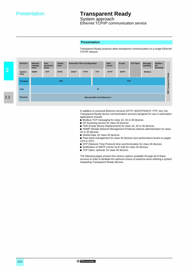
Transparent Ready products allow transparent communication on a single EthernetTCP/IP network.
In addition to universal Ethernet services (HTTP, BOOTP/DHCP, FTP, etc), theTransparent Ready device communication services designed for use in automationapplications include:b Modbus TCP messaging for class 10, 20 or 30 devices.b I/O Scanning service for class 30 devices.b FDR (Faulty Device Replacement) for class 10, 20 or 30 devices.b SNMP (Simple Network Management Protocol) network administration for class20 or 30 devices.b Global Data, for class 30 devices.b Pass band management for class 30 devices (see performance levels on pages2/24 to 2/27).b NTP (Network Time Protocol) time synchronization for class 30 devices.b Notification of SMTP events via E-mail for class 30 devices.b TCP Open, optional, for class 30 devices.
The following pages present the various options available through all of theseservices in order to facilitate the optimum choice of solutions when defining a systemintegrating Transparent Ready devices.
Presentation
Services
Applica-tions
Transport
Link
Physical
Networkmanage-ment
GlobalData
Automatic FDR reconfiguration Webserver
Messagehandling
ModbusI/OScanning
SNMP RTPS DHCP TFTP FTP HTTP Modbus
UDP TCP
IP
Ethernet 802.3 and Ethernet II
MIB
Tra
nsp
aren
tR
ead
y
TCP OpenE-mail
SMTP
Timesynchroni-zation
NTP

2/13
2
2.2
Functions Transparent Ready 0
System approachEthernet TCP/IP communication service
The HTTP protocol (Hypertext Transfer Protocol) is used for transmitting Web pagesbetween a server and a browser. HTTP has been used on the Web since 1990.
Web servers embedded into Ethernet TF devices are at the heart of the TransparentReady concept, and are used to provide easy access to devices anywhere in theworld from a standard browser such as Internet Explorer or Netscape Navigator.
BOOTP/DHCP is used to automatically provide the devices with the IP parameters.This avoids having to manage the addresses of each device individually.Management is instead performed in a dedicated IP address server.DHCP protocol (Dynamic Host Configuration Protocol) is used to automaticallyassign the devices their configuration parameters. DHCP is an extension of BOOTP.DHCP protocol is made up of 2 components:b One for providing the IP network address,b One for providing the IP parameters specific to the device from a DHCP server.
Telemecanique devices can be:b BOOTP clients allowing automatic recovery of an IP address from a server,b BOOTP servers enabling a device to distribute IP addresses to the networkstations.Telemecanique uses standard BOOTP/DHCP protocols for its Faulty DeviceReplacement service (FDR).
File Transfer Protocol (FTP) provides basic file sharing elements. Many systems useFTP protocol to exchange files between devices.
Transparent Ready devices implement FTP for transferring certain data to or fromdevices, in particular when downloading firmware or user Web pages.
FunctionsStandard Ethernet servicesHTTP “Hypertext Transfer Protocol” (RFC1945)
BOOTP/DHCP (RFC1531)
FTP “File Transfer Protocol” (RFCs 959, 2228, et 2640)

2/14
2
2.2
Functions (continued) Transparent Ready 0
System approachEthernet TCP/IP communication service
NTP (Network Time Protocol) is used to synchronize the time of a client or serverdevice from a time server. Depending on the network used, it provides the followingtime precisions based on the UTC:b Several milliseconds on a local area network (LAN).b Several tens of milliseconds on a wide area network (WAN).
SMTP (Simple Mail Transfer Protocol) is an E-mail transmission service. It is used tosend E-mail between a sender and a recipient via an SMTP E-mail server.
The Internet community developed standard SNMP for managing the differentcomponents of a network through a single system. The network management systemcan exchange data with SNMP agent devices. This function enables the manager toview the status of the network and devices, modify their configuration and feed backalarms in the event of failure.
Transparent Ready devices are SNMP-compatible and can be integrated naturally ina network managed via SNMP.
COM/DCOM (Distributed Component Object Model) or OLE (Object Linking andEmbedding) is the name of the technology used in Windows components. Thisenables Windows applications to communicate transparently.
These technologies are used in the OFS Data server software.
Functions (continued)
Standard Ethernet services (continued)
NTP “Network Time Protocol” (RFC 1305)
SMTP “Simple Mail Transfer Protocol” (RFC 0821)
SNMP “Simple Network Management Protocol” (RFCs 1155, 1156 et 1157)
COM/DCOM “Distributed Component Object Model”

2/15
2
2.2
Functions (continued) Transparent Ready 0
System approachEthernet TCP/IP communication service
Modbus, the industrial communication standard since 1979, has been combined withEthernet TCP/IP, which supports the Internet revolution, to make Modbus TCP/IP, acompletely open Ethernet protocol. The development of a connection to ModbusTCP/IP requires no proprietary component or license purchase.This protocol may be easily combined with any device supporting a standard TCP/IPcommunication stack. Specifications can be obtained free of charge from thewebsite: www.modbus-ida.org.
The Modbus application layer is very simple and universally recognized. Thousandsof manufacturers are already implementing this protocol. Many have alreadydeveloped a Modbus TCP/IP connection and many products are currently available.The simplicity of Modbus TCP/IP enables any small field team, such as an I/Omodule, to communicate over Ethernet without the need for a powerfulmicro-processor or a lot of internal memory.
Because of the simplicity of its protocol and the high speed of 100 M bits/s Ethernet,Modbus TCP/IP delivers excellent performance. This means it is possible to use thistype of network in real-time applications such as I/O Scanning.
An identical application protocol is used for Modbus serial link, Modbus Plus orModbus TCP. This therefore makes it possible to route messages from a network toanother without changing protocol.As Modbus is implemented above the TCP/IP layer, users can also benefit from theIP routing which enables devices located anywhere in the world to communicatewithout having to worry about the distance between them.Schneider offers an entire range of gateways for interconnecting a Modbus TCP/IPnetwork to already existing Modbus Plus or Modbus serial link networks. For furtherdetails, consult our regional sales office.The IANA institute (Internet Assigned Numbers Authority) has assigned Schneiderport TCP 502 (Well known port), which is reserved for the Modbus protocol. Thisprotocol will shortly be also subject to an RFC (Request For Comments), documentswhich form standard references within the Internet community.
Maximum size of data:b Read: 125 words or registers.b Write: 100 words or registers.
Functions (continued)
Modbus communication standardModbus TCP/IP function codes dec hexaBits access Read of n input bits 02 02
Read of n output bits 01 01
Exceptional read status 07 07Write 1 output bit 05 05
Write of n output bits 15 0F
Read of 1 input word 04 04
Read of n input words 03 03
Write 1 output word 06 06
Write of n output words 16 10Read device ID 43/14 2B/0E
Example of Modbus TCP/IP function codes supported foraccessing data and diagnostics
Modbus TCP, simple and open
Modbus TCP, high-performance
Modbus TCP/IP, one standard
Modbus TCP/IP characteristics

2/16
2
2.2
Functions (continued) Transparent Ready 0
System approachEthernet TCP/IP communication service
The I/O Scanning service can be used to manage the exchange of distributed I/Oson the Ethernet network after a simple configuration operation, with no need forspecial programming.The I/Os are scanned transparently by means of read/write requests according to theModbus Master/Slave protocol on the TCP/IP profile. This principle of scanning viaa standard protocol enables communication with any device which supports aModbus server on TCP/IP.This service can be used to define:b An %MW word zone reserved for reading inputs.b An %MW word zone reserved for writing outputs.b Refresh periods independent of the PLC scan.During operation, the module:b Manages the TCP/IP connections with each of the distributed devices.b Scans the devices and copies the I/Os into the configured %MW word zone.b Feeds back status words so that correct operation of the service can be monitoredfrom the PLC application.b Applies the preconfigured fallback values in the event of a communicationproblem.
An offer of hardware and software products which enable the I/O Scanning protocolto be implemented on any type of product which can be connected to the Ethernetnetwork (please consult: www.modbus-ida.org).
Characteristics:b Each station can exchange a maximum of 120 words.b Maximum size in the PLC managing the service:v 2 K words %MW in inputs and 2 K words %MW in outputs with manager PLC(64 stations max.),v 4 K words %MW in inputs and 4 K words %MW in outputs with manager PLC(128 stations max.).
I/O Scanning service diagnostics can be performed in 3 ways:b By the application program from a data field specific to the PLC.b From the debugging screen in the installation software.b From the PLC system diagnostics function viewed with the Internet browser on aPC station.
Functions (continued)
I/O Scanning service
INPUT
OUTPUT+–
INPUT
OUTPUT+–
A
B
A
B
Word table
Read Write
Ethernet TCP/IP
Input wordsOutput words ofdevices
I/O Scanning service diagnostics

2/17
2
2.2
Functions (continued) Transparent Ready 0
System approachEthernet TCP/IP communication service
The Faulty Device Replacement service uses the standard BOOTP, DHCP, filemanagement and TFTP technologies with the objective of simplifying Ethernetdevice maintenance.
It enables a faulty device to be replaced by a new product while guaranteeing itsdetection, reconfiguration, and automatic restart by the system, without difficultmanual intervention.
The principal steps are:b A device using the FDR service is faulty.b Another similar device is taken from the maintenance pool, preconfigured with the“role_name” (or identifier) of the device that is out of service, then reinstalled on thenetwork.b The FDR server can be:v Premium processor with embedded Ethernet,v Quantum processor with embedded Ethernet,v Premium Ethernet module: TSX ETY,v Quantum Ethernet module: 140 NOE 771,detects the new addition, configures its IP address and transfers all configurationparameters to it.
The substituted device verifies if all the parameters are indeed compatible with itsown characteristics, then switches to operating mode.
Functions (continued)
Replacement service for faulty devices (Faulty Device Replacement)

2/18
2
2.2
Functions (continued) Transparent Ready 0
System approachEthernet TCP/IP communication service
Characteristics: A maximum of 64 stations can participate in Global Data within thesame distribution group.Each station can:b Publish one 1024-byte variable. The publication period can be configured from1 to n periods of the MAST task of the processor.b Subscribe to between 1 and 64 variables. Validity for each variable is controlled byHealth Status Bits, linked to a refresh timeout configurable between 50 ms and 1 s.Access to a variable element is not possible. The total size of the subscribedvariables reaches 4 K contiguous bytes.In order to optimize Ethernet network performance further still, Global Data can beconfigured with the "multicast filtering" option, which together with switches in theConneXium range, perform data broadcasting only on Ethernet ports, where there isa Global Data service subscriber station. If these switches are not used, Global Datais transmitted in "multicast" on all switch ports
The diagnostics screens use a color code to show Global Data status:b Configured/not configured/faulty.b Published/subscribed.
The Unity Studio software suite is the key component required on design officeworkstations used for designing and structuring distributed industrial automationprojects.
The Unity Studio Global Data view enables the definition of Global Data distributiongroups and the configuration of settings for published and subscribed stationvariables. During generation at each station level, this setting configuration is savedautomatically to station files, thereby ensuring:
b Guaranteed consistency of communication between the distributed applications inquestion.b Maximum productivity with respect to station configuration tasks.b Minimized risk of errors.
Functions (continued)
Global Data service
The Global Data service ensures data exchanges inreal time between stations belonging to the samedistribution group. It is used to synchronize remoteapplications, or share a common database amongseveral distributed applications.The exchanges are based on a standardproducer/consumer protocol, guaranteeing optimalperformance while maintaining a minimum networkload. This RTPS (Real Time Publisher Subscriber)protocol is promoted by the IDA (Interface ForDistributed Automation) organization, and has alreadybeen adopted as a standard by several manufacturers.
INPUT
OUTPUT+–
INPUT
OUTPUT+–
A
B
A
B
Distribution group 1Data exchange of 4 Ko max.
Data exchange of 4 Ko max.Distribution group 2
IP multicast 239.255.255.251
IP multicast 239.255.255.250
Ethernet TCP/IP
Global Data service diagnostics
Unity Studio software suite: single Global Data entry point
Editeur de Global Data
2/19
2
2.2
Functions (continued) Transparent Ready 0
System approachEthernet TCP/IP communication service
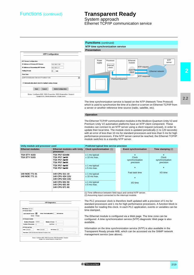
The time synchronization service is based on the NTP (Network Time Protocol)which is used to synchronize the time of a client or a server on Ethernet TCP/IP froma server or another reference time source (radio, satellite, etc).
The Ethernet TCP/IP communication modules in the Modicon Quantum Unity V2 andPremium Unity V2 automation platforms have an NTP client component. Thesemodules can connect to an NTP server using a client request (unicast), in order toupdate their local time. The module clock is updated periodically (1 to 120 seconds)with an error of less than 10 ms for standard processors and less than 5 ms for highperformance processors. If the NTP server cannot be reached, the Ethernet TCP/IPmodule switches to a standby NTP server.
(1) Time difference between field input and central NTP server.(2) Assuming input connected to the interrupt module.
The PLC processor clock is therefore itself updated with a precision of 5 ms forstandard processors and 1 ms for high performance processors. A function block isavailable for reading this clock. In each PLC application, events or variables can betime-stamped.
The Ethernet module is configured via a Web page. The time zone can beconfigured. A time synchronization service (NTP) diagnostic Web page is alsoavailable.
Information on the time synchronization service (NTP) is also available in theTransparent Ready private MIB, which can be accessed via the SNMP networkmanagement service (see above).
Functions (continued)
NTP time synchronization servicePresentation
Powersupply
Processor Ethernetmodule
Internalclock
Ethernet network
NTPserver
Premium/QuantumNTP response
NTP request
(S)NTPclient
Operation
Unity module and processor used Predicted typical time service precisionEthernet modules Ethernet modules with Unity
processorClock synchronisation (1) Event synchronisation Time stamping (2)
TSX ETY 4103TSX ETY 5103
TSX P57 0244MTSX P57 1p4MTSX P57 2p4MTSX P57 3p4M
± 1 ms typical± 10 ms max.
=Clock
synchronisationprecision
+
Fast task time
+
I/O time
=Clock
synchronisationprecision
+
I/O time
TSX P57 4p4MTSX P57 5p4M
± 1 ms typical± 5 ms max.
140 NOE 771 01140 NOE 771 11
140 CPU 311 10140 CPU 434 12U140 CPU 534 14U
± 1 ms typical± 10 ms max.
140 CPU 651 50140 CPU 651 60140 CPU 671 60
± 1 ms typical± 5 ms max.

2/20
2
2.2
Functions (continued) Transparent Ready 0
System approachEthernet TCP/IP communication service
This simple mail notification service is a programmed service that allows PLCapplications to report by exception conditions monitored by the PLC. The automationcontroller can automatically and dynamically create electronic mail to alert specifiedusers with data, alarms and events - whether the recipients are local or remote.
Note: This service is available on the latest Premium and Quantum Ethernet modules& CPUs, when operating with Unity Pro software. A more comprehensive mailservice, independent of the PLC application, is available on the FactoryCast HMIactive web server modules (see page 2/11)
A simple yet powerful mechanism is used. Predefined email headers are linkedtogether with the body of the mail which is created dynamically from the latestinformation in the automation application.
The user logic program can trigger the message based on a predefined event orcondition. Using a function block, one of 3 predefined headers is selected and anemail message with variable information and text (up to a maximum of 240 bytes) iscreated and sent directly from the PLC.
Each of the three mail headers contains these common predefined items –emailrecipient list, sender name and subject. This information can be defined and updatedby an authorized administrator using the configuration web pages.
The PLC application selects the appropriate header. The system architect maydefine the mail headers to indicate differing importance levels. For example :b Header 1 could be “URGENT problem reported by PLC 10”,b Header 2 might be “WARNING at substation 10”,b Header 3 could be “INFO message from water system”.
Differing lists of recipients between the three headers help to ensure that the rightinformation quickly flows to the right recipients. The application can then addpertinent information to the body of the mail message such as the specific device,process or location.
Completed mail is then sent to an electronic mail server for expeditious distributionto the interested parties. These recipients could be engineers, managers, processowners etc.
Each mail message can be protected by an optional login and password that isauthenticated by the SMTP mail server. If, for additional security, the site’s mailinstallation has changed the TCP port number from the default of 25, the port numbercan be changed in the PLC email configuration (via secured web page access).
An authorized administrator can use a web page to easily configure the mail service.For each of the three mail headers, the sender; recipient list and subject messagecan be defined. The electronic mail server connection information such as IP addressand security information can also be set from the web page.
As all other Ethernet services in Premium and Quantum systems, the Mail Servicehas a Diagnostic Web page showing the complete, up to the second, status.
These products provide diagnostic information for remote management applicationsfollowing the SNMP network management standard. Information for the mail serviceis included in the Schneider Electric private MIB which is publicly available.
Functions (continued)
Electronic mail notification SMTP serviceIntroduction
Usage
Message creation and delivery
Security
Configuration
Diagnostics
Remote Monitoring

2/21
2
2.2
Functions (continued) Transparent Ready 0
System approachEthernet TCP/IP communication service
The SNMP (Simple Network Management Protocol) protocol is used, from a networkmanagement station, to monitor and control all Ethernet architecture componentsand thus ensure rapid diagnostics if a problem occurs.It is used to:b Query devices such as computer stations, routers, switches, bridges or terminaldevices (DTE) in order to view their status.b Obtain statistics for the network on which the devices are connected.
This management software respects the traditional Client/Server model. However, inorder to avoid confusion with other communication protocols using this terminology,we prefer to use the expression:b Network manager for the Client application running on the computer station.b SNMP agent for the server application that runs on the device.Transparent Factory can be managed by any SNMP network manager, includingHP Openview or IBM Netview.
Standard SNMP (Simple Network Management Protocol) is used to accessconfiguration and management objects included in the MIB (ManagementInformation Base) for the devices. These MIBs must comply with certain standardsin order to be accessed by all managers on the market. However, depending on thedevice complexity, manufacturers can add certain objects to the private databases.
The Transparent Factory private MIB includes management objects specific to theTelemecanique offer. These objects simplify installation, implementation, andmaintenance for Transparent Factory products in an open environment usingstandard network management tools.The Transparent Factory products support 2 SNMP network management levels:b Standard MIB II, a first level of network management, can be accessed via thisinterface. It lets the manager identify the devices forming the architecture andretrieve general information on the configuration and operation of the EthernetTCP/IP interfaces.b MIB Transparent Factory interface; management of the Transparent Factorydevices is improved via this interface. This MIB includes a set of data that enablesthe network management system to supervise all the Transparent Factory services.The Transparent Factory private MIB can be downloaded from the Web server fromany Ethernet Transparent Factory module in a PLC.
Functions (continued)
SNMP service protocol

2/22
2
2.2
Functions (continued) Transparent Ready 0
System approachEthernet TCP/IP network
TSX ETY 110 WS/5103 Premium platform Ethernet modules support a number ofcommunication protocols based on the TCP/IP standard.Among these, the Modbus protocol has public specifications and its simplicityrecommends it for the needs of communication with third-party devices.
However, for certain applications, it may prove necessary to use other protocols.This is the case when, for example, users wish to integrate Premium platforms intoexisting architectures which use a particular communication protocol, possibly aproprietary one.To meet these needs for open access, 2 interface levels are included in theTelemecanique offer:b A library of basic functions, which can be used in C language, enables directaccess to the socket interface on TCP. The user can thus create his owncommunication functions using SDKC development software and take advantage ofthe ease of use which this program offers in terms of development and debugging.Once generated, these function blocks are used in the application like any standardPL7 programming software function block.b A library of basic function blocks known as EFs, which can be used directly in theapplication programs with PL7 language. These are the same as functionsdeveloped in C language seen earlier, but are designed for use by non-computerspecialists. These EF function blocks are not modifiable.
Operating in TCP connection client/server mode, the basic functions on the Berkeleysocket interface enable:
b Management of 16 connections on the Open profile out of a maximum of 32b Creation of sockets and their attachment to any TCP port.b Switching of these sockets to "listen for a connection request from a remote client"mode.b Opening of a connection.b Transmission and reception of data on these connections (8 bytes max.).b Closing this connection.
TCP open optional servicePresentation
Ethernet TCP/IP profile
Modbus protocol
DirectSocket access
(TCP Open)
TCP
IP
ISO 8802.2-ISO 8802.3
ISO 8802.3 Ethernet10/100 M bit/s
Modbus
Functions

2/23
2
2.2
Functions (continued) Transparent Ready 0
System approachEthernet TCP/IP network
The TCP Open offer consists of a CD-ROM containing the TCP/IP function libraries.Open access on TCP is only possible via TSX ETY 110WS (1) and TSX ETY 5103Ethernet modules. With open access on TCP, all the basic functions of thesemodules can be used.
The TCP/IP TLX CD TCP 50M function library comprises:b The SDKC program enhancement library that provides access to the moduleTCP/IP socket functionsb The user's manual in English (no printed version)b EF elementary communication function blocks (Socket/Bind/Listen/Accept/Shutdown/Close/Send/Receive/Select/Set_Socket Option/Connect) for installationusing PL7 software (version u V3.3)b Higher level EF function blocks, provided by way of example, which can performmore advanced functions such as the complete sequence for establishing or closinga connection, or sending or receiving data. The source files for all these EF blocksare also suppliedb An example of a PL7 application communicating with a TELNET application on aPC
If customised function blocks are needed both the SDKC program for C languageTLX L SDKC PL741M (with PL7) or UNY SPU ZU CD 20E (with Unity Pro) and thelibrary of function blocks TCP Open TLX CD TCPA33E should be installed on thedevelopment station.
The development of C language functions requires compliance with certain setupprecautions:b To set up these services, the user should be familiar with the TCP/IP profileb In addition, since the SDKC program enables access to all the PLC internalresources, all the necessary precautions should be taken when developing EFcommunication blocks to avoid endangering the PL7 application, especially on thecommonly fragile operating modes such as cold/warm restarts, response to a fault, etcb The user should also take care to maintain the requests from the differentcommunication profiles at a level compatible with the performance required by theapplicationb Finally, it is the responsibility of the client application software (PL7 or C program)to manage the operating modes for communication which may be specific to theapplication, for example the behavior if a remote device fails to respond or in theevent of a break in connection
For these different reasons, we recommend that you consult your Regional SalesOffice to ensure that your TCP protocol open access project is feasible.
(1) Open access on TCP requires TSX ETY 110 WS modules, version u PV 03 and SV 2.9. Inaddition, it should be integrated on a configuration with a TSX P57 pp3 processor(or TSX P57 pp2 version > V3.3).
Service optionnel ouverture TCP Open (suite)
Description
Setup precautions

2/24
2
2.3
Performances Transparent Ready 0
System approachPremium/Quantum platform performanceEthernet TCP/IP network
When selecting an architecture, it is advisable to take performance into account atthe earliest possible stage.For this, the designer must:1 Have a clear idea of his needs as regards:v quantity and type of devices to be interconnected,v volume and type of exchanges,v expected response times,v environment.2 Compare his needs with the characteristics of the offers available and be aware
that the precise performance level between any 2 points on an architecture isdependent on the weakest link in the chain, which can be:
v a function of the hardware,v but also a function of the applications (size, architecture, OS, machine power, etc.)which are often poorly defined at this stage of project.3 Select the most suitable architecture.
The objective of the following pages is to answer the second point by explaining theperformance of the different components which constitute an Ethernet architecture,concentrating on the following 2 aspects:b Processing capacity in terms of volume of exchanges (see pages 2/25 and 2/26).b Application response time (see page 2/27).
As in any communication system, the performance of an Ethernet architecture islinked to numerous parameters which depend on the:b Hardware used:v network bandwidth,v resources of module or CPU with Ethernet embedded,v processor resources (PLC, PC or other CPUs).b Application services used:v Modbus (or Uni-TE) industrial messaging handling service,v Global Data service, data scanning between PLC,v I/O Scanning service, data scanning of distributed I/O,v Others (Web access, TCP Open communication).The difficulty in determining the correct size of an architecture is due to the fact thatthe majority of these parameters are linked.
Nota : For purposes of simplification, the values shown in the tables which follow have beenreduced. If these are adhered to, correct operation of the architecture is ensured. If theperformance levels obtained are not sufficient, please consult our Regional Sales Office for amore detailed study.
Nota : The performance levels indicated depend relatively little on the size of messages. Limiting factorshave much more to do with the number of messages. It is therefore necessary to group as much usefulinformation as possible within the same message using the most suitable Modbus request.
The methodology presented below in 4 steps can be used to determine the messageprocessing capacity on Ethernet TCP/IP.
Using the tables below, calculate the exchanges necessary for the application, i.e.for each station on the architecture and for each service used, the number ofmessages to be transmitted and received per second.
Selecting the communication architecture
Introduction
Processing capacity in terms of volume of exchanges
Step 1: calculation of exchanges necessary for the application
Messages transmitted per second from Total numberof messages receivedper station
Station A Station B Station N
Messages persecond sent to
Station A R1Station B R2
Station N Ri
Total number of messagestransmitted per station
E1 E2 Ei Network loadCru = Σ [R1…Ri, E1…Ei]
Not applicable

2/25
2
2.3
Performances (continued) Transparent Ready 0
System approachPremium/Quantum platform performanceEthernet TCP/IP network
Using the table below, compare the total number of messages received via theModbus and Uni-TE service for each station (value R1, R2 or Ri) with the stationprocessor processing capacity.If the result of this initial calculation is positive, go to step 3.
For each station, compare the total number of messages received (Σ [values Ri, Rj]and the total number of messages transmitted (Σ [values Ei, Ej] for station N, forexample) with the bus or network processing capacity shown below. If the result ofthis second calculation is positive, go to step 4.
b Modbus requests:v 125 words or registers in read access,v 100 words or registers in write access.b Global Data: 1024-word published variable, subscription to a maximum of64 variables, with a maximum size of 2 K %MW.b I/O Scanning with maximum size in the PLC managing the service:v 2 K %MW in inputs and 2 K %MW in outputs with manager PLC limited to 64stations,v 4 K %MW in inputs et 4 K %MW in outputs with manager PLC limited to 128stations (TSX P57 50, 140 CPU 65 150/160 et 140 CPU 67 160).
(1) A temporary overload on several PLC cycles, due, for example, to an adjustment terminal orthe temporary connection of an Internet browser, is acceptable.
(2) Only with Unity Pro.(3) Only with Concept/ProWORX.(4) With Unity Pro version V2.0, 1 message/cycle with version V1.0.(5) I/O Scanning and Gobal Data services are not available for TSX WMY 100 and
140 NWM 100 00 modules.
Step 2: station processor processing capacity, system requests
Premium or Atrium platform Messages being received Messages beingtransmitted
Communication by EFs or EFBs (PL7 or Unity Pro)Modbus requests(1)
TSX 57 10 4 mes/cyc Does not constitute alimiting factorTSX 57 20 8 mes/cyc
TSX 57 30 12 mes/cyc
TSX 57 40 16 mes/cyc
TSX 57 50 (2) 16/20 mes/cyc
Quantum platform Messages being received Messages beingtransmitted
Communication by EFs or EFBs (Concept, ProWORX or Unity Pro)
Modbus requests(1)
CPU 113 02/03 (3) 1 mes/cyc 4 mes/cyc
CPU 311 10 (2) 1 mes/cyc 4 mes/cyc
CPU 434 12p 1 mes/cyc 4 mes/cycCPU 534 14p 1 mes/cyc 4 mes/cyc
CPU 651 p0 (2) 16 mes/cyc (4) 4 mes/cyc
CPU 671 60 (2) 16 mes/cyc (4) 4 mes/cyc
mes/cyc: number of messages being received per cycle from the PLC master task (typical cyclefrom 50 to 100 ms).
Step 3: bus or network module processing capacity
Processing capacity of Ethernetconnections
Premium Ethernet TCP/IP Quantum Ethernet TCP/IPTSX ETY 110/210TSX ETY 110WS
TSX ETY 4103/5103TSX WMY 100 (5)TSX P57 10/20/30/40
TSX P57 50 140 NOE 771 pp140 NWM 100 00 (5)
140 CPU 65 150/160140 CPU 67 160
Message transactions 60 transactions/s 450 transactions/s 500 transactions/s 350 transactions/s 350 transactions/s
Scanning I/O polling Service not available 2000 transactions/s 2000 transactions/s 2000 transactions/s 2000 transactions/s
Global Data subscriptions 800 transactions/s 800 transactions/s 800 transactions/s 800 transactions/s
Characteristics summary
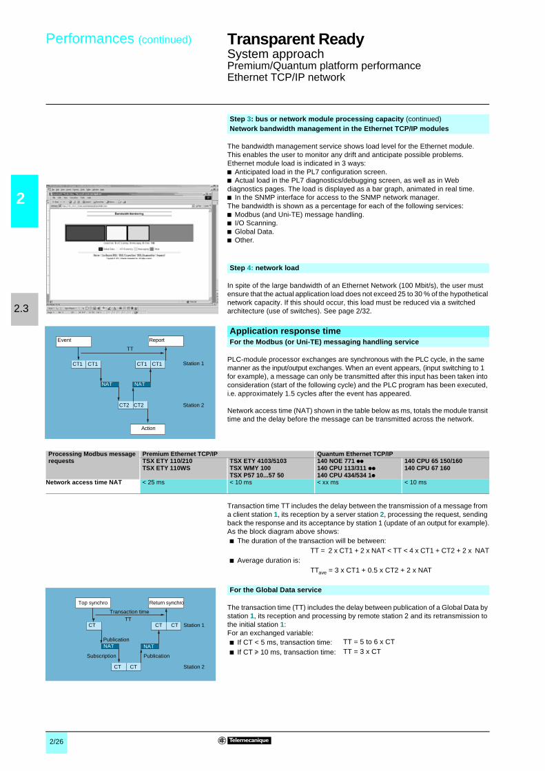
2/26
2
2.3
Performances (continued) Transparent Ready 0
System approachPremium/Quantum platform performanceEthernet TCP/IP network
The bandwidth management service shows load level for the Ethernet module.This enables the user to monitor any drift and anticipate possible problems.Ethernet module load is indicated in 3 ways:b Anticipated load in the PL7 configuration screen.b Actual load in the PL7 diagnostics/debugging screen, as well as in Webdiagnostics pages. The load is displayed as a bar graph, animated in real time.b In the SNMP interface for access to the SNMP network manager.The bandwidth is shown as a percentage for each of the following services:b Modbus (and Uni-TE) message handling.b I/O Scanning.b Global Data.b Other.
In spite of the large bandwidth of an Ethernet Network (100 Mbit/s), the user mustensure that the actual application load does not exceed 25 to 30 % of the hypotheticalnetwork capacity. If this should occur, this load must be reduced via a switchedarchitecture (use of switches). See page 2/32.
PLC-module processor exchanges are synchronous with the PLC cycle, in the samemanner as the input/output exchanges. When an event appears, (input switching to 1for example), a message can only be transmitted after this input has been taken intoconsideration (start of the following cycle) and the PLC program has been executed,i.e. approximately 1.5 cycles after the event has appeared.
Network access time (NAT) shown in the table below as ms, totals the module transittime and the delay before the message can be transmitted across the network.
Transaction time TT includes the delay between the transmission of a message froma client station 1, its reception by a server station 2, processing the request, sendingback the response and its acceptance by station 1 (update of an output for example).As the block diagram above shows:
The transaction time (TT) includes the delay between publication of a Global Data bystation 1, its reception and processing by remote station 2 and its retransmission tothe initial station 1:For an exchanged variable:
Step 3: bus or network module processing capacity (continued)Network bandwidth management in the Ethernet TCP/IP modules
Step 4: network load
Application response timeFor the Modbus (or Uni-TE) messaging handling service
Station 1
Event
CT1
NAT NAT
CT2 CT2 Station 2
Report
TT
CT1 CT1 CT1
Action
Processing Modbus messagerequests
Premium Ethernet TCP/IP Quantum Ethernet TCP/IPTSX ETY 110/210TSX ETY 110WS
TSX ETY 4103/5103TSX WMY 100TSX P57 10...57 50
140 NOE 771 pp140 CPU 113/311 pp140 CPU 434/534 1p
140 CPU 65 150/160140 CPU 67 160
Network access time NAT < 25 ms < 10 ms < xx ms < 10 ms
b The duration of the transaction will be between:TT = 2 x CT1 + 2 x NAT < TT < 4 x CT1 + CT2 + 2 x NAT
b Average duration is:TTave = 3 x CT1 + 0.5 x CT2 + 2 x NAT
For the Global Data service
b If CT < 5 ms, transaction time: TT = 5 to 6 x CT
b If CT u 10 ms, transaction time: TT = 3 x CT
Station 1
Top synchro
CT CT CT
NAT NAT
CT CT Station 2
Return synchro
TTTransaction time
Publication
PublicationSubscription

2/27
2
2.3
Performances (continued) Transparent Ready 0
System approachPremium/Quantum platform performanceEthernet TCP/IP network
The RT application response time include the delay between getting data from aremote input and up dating remote output. It includes PLC application treatment time.
This RT response time is composed of following parameters:
b TMod In and TMod Out: response time of the read/written device excluding theinput circuit transition (TMod depends of the device, but commonly between 1 to8 ms).b TIOS In and TIOS Out: time between two scanning of the same read device(0.3 ms x number of device scanned and at least the pooling rate configured. TIOSis executed in parallel of the CPU cycle time, so could be hidden for the RT responsetime).b N: number of PLC CPU cycles.b CycleT: CPU cycle time.b Tnet: propagation time on the network (depending of the application, butcommonly Tnet is 0.05 ms at 10 Mbit/s and 0.005ms at 100 Mbit/s).
The RT response time could be estimated using the following formulas:
b TRmin, minimal response time with TIOS hidden and 1 CycleT:TRmin = Tmod In + 0 x TIOS In + Tnet + 1 x CycleT + 0 x TIOS Out + Tnet + TModOut
b TRtypic, typical response time (with 0,5 TIOS hidden and 2 CycleT:TRtypic = TMod In + 0.5 x TIOS In + Tnet + 2 x CycleT + 0.5 x TIOS Out + Tnet +TMod Out
b TRmax, maximal response time with TIOS not hidden and 3 CycleT:TRmax = TMod In + TIOS In + Tnet + 3 x CycleT + TIOS Out + Tnet + TMod Out
The TMod In and TMod out response time are shown below:
The TIOS In and TIOS Out times mesured between two scanning are shown below:
Application response time (continued)
I/O Scanning service
Type of distributed I/O Response time Mini Typical MaxiMomentum 170 ENT 110 02 TMod In 1 ms 1 ms 1 ms
TMod Out 5 ms 5 ms 5 ms
Momentum 170 ENT 110 01 TMod In or TMod Out 4 ms 6 ms 8 ms
Advantys STB NIP 2212 TMod In or TMod Out 2 ms 3 ms 4 ms
Device 1
Device 2
Manager
Hub
Input
Output
CT
RT
Ethernet TCP/IP
Response time (RT)
Input
Output
TMod In
TMod Out
TIOS In
TNet
NxCycleTTIOS Out
TNet
0
5
10
15
20
25
1 5 10 20 30 40 50 60
Mesured TIOS(Network with switches)
Number of scanning products
Tim
e(m
s)

2/28
2
2.4
Presentation,characteristics
Transparent Ready 0
System approachEthernet infrastructure ConneXium wiring system
Industrial Ethernet networks can use various standards. In each case, a set of rulesmust be respected when determining what topology will be produced and with whatperformance level.
The ConneXium offer comprises a complete family of industrial products used tobuild a network architecture: hubs, switches, transceivers and cables. Wiring rulespertaining to the ConneXium offer are described on pages 2/28 to 2/33.
(1) SFTP cables (Shielded and Foiled Twisted Pair) are available in 2 versions:v UL 1581 vertical tray, NFC 32070 level C1, IEC 332-1.v Reaction to fire compliant with NFC 32 070 # class C2 and IEC 332-1, Low Smoke ZeroHalogen (LSZH) and UL 1581 VW1.
(2) The mutimode fiber is Low Smoke Zero Halogen as per HD.624-7, with reaction to firecomplying with NFC 32 070 # class C2 and IEC 332-1.
The Ethernet 802.3 Link Layer is based on a collision detection mechanism(CSMA CD). Each station (DTE, Data Terminal Equipment) sends its data whennecessary and verifies if the frame has been correctly propagated. If a collision witha frame sent by another station is detected, the station repeats the message after atimeout, which increases the network load and thus the probability that anothercollision will occur.
The transceivers or hubs (repeaters) are used to regenerate the signal once thephysical limits of the medium have been reached. They also propagate collisions, ifthere are any.
Because of the transmission time needed to send data from one end of the networkto the other, a maximum network length exists, beyond which collisions might not bedetected by the sender. For this reason, and for each technology, a network size limithas been set. This is described as the “maximum network diameter” within a samecollision domain.
Presentation
CharacteristicsGeneral characteristics for industrial Ethernet standardsStandard Date rate
(Mbit/s)Medium Type of connector Useable bandwidth
(on automationnetwork)
Advantages
10BASE5 10 Thick coaxial cable(yellow)
15-way SUB-D (AUI) 8 %, i.e. 800 Kbit/s Cost, Ethwaycompatibility
10BASE-T 10 Twisted shielded pair(SFTP) (1)
RJ45 8 %, i.e. 800 Kbit/s Cost
10BASE-FL 10 Fibre optic (generally62.5/125 multimode1300 µm (2)
ST or MT-RJ 8 %, i.e. 800 Kbit/s Immunity,confidentiality
100BASE-TX 100 Shielded twisted pair(SFTP)
RJ45 40 %, i.e. 40 Mbit/s Data rate (x 50)
100BASE-FX 100 Fibre optics SC or MT-RJ 40 %, i.e. 40 Mbit/s Immunity
Installation principles
Presentation:page 2/28
Installation rules:pages 2/28 to 2/33

2/29
2
2.4
Installation rules Transparent Ready 0
System approachEthernet infrastructure ConneXium wiring system
Various architectures may exist, depending on each standard:
b Line or bus topology, using transceivers.b Star network topology, using hubs.b Tree network topology, using hubs.
Transceivers are also used for transmitting signals between 2 dissimilar media suchas fiber optic and twisted pair cables.In addition, the hubs (or concentrators) are also used to transmit signals amongseveral media (ports).The transceivers and hubs are “plug and play” devices.
Note: in the information that follows, the terms “hubs” and “repeaters” are usedinterchangeably.
Depending on the Ethernet standard employed, the network size can vary. To definethe correct architecture, the 2 constraints of maximum segment length and maximumnetwork diameter must be respected. The Schneider Electric ConneXiumperformances make it possible, in some situations, to surpass the limits of the 802.3standard.
(1) Depends on the optical budget and fiber attenuation.
Architectures in a same collision domain
10BASE5 10BASE-T, 10BASE-F,100BASE-TX, 100BASE-FX
10BASE-T, 10BASE-F,100BASE-TX, 100BASE-FX
DTE
DTEDTE
Line or bus topology
Transceiver
DTE DTE
DTE DTE
Star topology
Hub
DTE DTE
Tree topology
Hub
Rule 1: to respect the “maximum network diameter” within a same collisiondomain
Ethernetstandard
Maximum segment length(physical limit)
Maximum network diameter(limited by collisions)
Type According tostandard 802.3
WithConneXiumproducts
According tostandard 802.3
WithConneXiumproducts
10BASE5 500 m(50 m for a drop cable)
1.800 m(2.800 m with fiber optic segment)
10BASE-T 100 m 500 m 1.000 m
10BASE-FL ormixed (FL and T)
2.000 m 3.100 m(1)
2.500 m 3.100 m(1)
100BASE-TX 100 m 200 m
100BASE-FX inHalf Duplex
412 m 228 m or 412 m between 2 DTEdevices
100BASE-FX inFull Duplex
2.000 m 3,000 m withmultimode15.000 m withmonomode(1)
228 m or 412 m between 2 DTEdevices
Presentation:page 2/28
Installation rules:pages 2/28 to 2/33

2/30
2
2.4
Installation rules (continued) Transparent Ready 0
System approachEthernet infrastructure ConneXium wiring system
Between 2 DTE (Data Terminal Equipment) devices, a maximum of 2 repeaters or1 repeater with 2 half-repeaters (half-repeaters ensure transmission between acopper and a fiber optic medium):b Drop cable, 50 m length max.,b One segment, 500 m length max.,b Between 2 fiber optic half-repeaters, 1000 m length max.
Examples:b All copper, 1,800 m length max.
b Mixed copper/fiber optic, 2,800 m length max.
Between 2 DTE devices, a maximum of 5 segments and 4 hubs (or repeaters).
b Topology of 5 segments and 4 hubs (or repeaters): each 10BASE-FL segmentmust have a length of < 500 m.b Topology of 4 segments and 3 hubs (or repeaters): the 10BASE-FL inter-repeatersegments must have a length of < 1,000 m, and the 10BASE-FL segments betweenhub and DTE devices must have a length of < 400 m.Examples:In the following 2 topologies, distances are usually given for the 10BASE-T standard,with distances for the 10BASE-F standard within parentheses.
Installation rules (continued)
Rule 2: for each technology, respect the following rules within the samecollision domain10BASE5
DTE DTE
Segment Segment Segment
Hub/repeater Hub/repeater
500 m 500 m 500 m
50 m 50 m 50 m 50 m 50 m 50 m
DTE DTE
Segment Segment Segment
Hub/repeater Half-repeater Half-repeater
500 m 500 m 500 m
1,000 m
50 m 50 m 50 m 50 m 50 m 50 m
10BASE-T/10BASE-F
Maximum 500 m in 10BASE-T, 2,500 m in 10BASE-F.
Maximum 400 m in 100BASE-TX, 2,800 m in 100BASE-FX
DTE DTE
Hub/repeater Hub/repeater
Hub/repeater Hub/repeater
100 m (500 m)
100 m (500 m)
100 m (500 m)
100 m (500 m)
100 m (500 m)
DTE DTE
Hub/repeater
Hub/repeater Hub/repeater
100 m (400 m)100 m (400 m)
100 m(1,000 m)
100 m(1,000 m)
Presentation:page 2/28
Installation rules:pages 2/28 to 2/33

2/31
2
2.4
Installation rules (continued) Transparent Ready 0
System approachEthernet infrastructure ConneXium wiring system
This Ethernet standard defines 2 classes of hubs (or repeaters):
b Class 1 hubs: Maximum of 1 hub in a same collision domain.b Class 2 hubs (for ConneXium repeaters): Maximum of 2 hubs in a same collisiondomain.
Examples:
In the following 4 topologies, distances are usually given for the 100BASE-TXstandard, with distances for the 100BASE-FX standard within parentheses.
Installation rules (continued)
Rule 2: for each technology, respect the following rules within the samecollision domain (continued)
100BASE-TX/100BASE-FX
200 m max. in 100BASE-TX, 300 m in mixed 320 m max. in 100BASE-FX
205 m max. in 100BASE-TX, 216 m in mixed
228 m max. in 100BASE-FX
DTE DTE
Class 1 hub/repeater
100 m 100 m(200 m)
DTE DTE
Class 1 hub/repeater
160 m 160 m
DTE DTE5 m100 m 100 m
(111 m)
Class 2 hub/repeater Class 2 hub/repeater
DTE DTE
Class 2 hub/repeater Class 2 hub/repeater
100 m 100 m28 m
Presentation:page 2/28
Installation rules:pages 2/28 to 2/33

2/32
2
2.4
Installation rules (continued) Transparent Ready 0
System approachEthernet infrastructure ConneXium wiring system
Switched devices enable the limits of the above-described architectures to beincreased. Switches are used for communicating between 2 or more collisiondomains. Communication for the upper layers is guaranteed among the differentports and collisions at the link layer level are not propagated (filtering).
Switches are “plug and play” devices that can be remotely administered via SNMPor HTTP. They essentially contribute 2 functions:
b Extension of the architecture to surpass the “maximum network diameter”.b Improvement of performance by a better allocation of bandwidth due to reductionin collisions and network load. In addition, switches in the ConneXium range supportmulticast filtering via the standard GARP/GMRP protocol, which optimizesperformances of the Global Data service. With these products, multicast frames aretransmitted only on switch ports where stations subscribing to the Global Dataservice are connected. ConneXium switches also support the Faulty DeviceReplacement (FDR) service, as well as the Transparent Ready private MIB formanaging devices via the SNMP network management protocol.
b Switches are DTE devices that can be connected to hubs or directly connected todevices. Rules 1 and 2, mentioned previously, thus apply.b When 2 switches are connected, the line can be in Full Duplex, which removes therisk of collisions and allows the effective data rate to be doubled. The rules related tothe collision domain thus do not apply, and only those imposed by the physical limitsshould be observed.For example, 2 switches may be connected on their 100BASE-FX ports via a fiberoptic cable 3,000 m in length.
Examples:
Maximum distances:b 100BASE-TX: 100 m between 2 switches.b 100BASE-FX: 2,000 m between 2 switches, 3,000 m with ConneXium switchesand up to 40 km using monomode optical fiber (outside supply).
Architectures with several collision domains
Rule 3: to be respected when switches are used
Switch used to isolate several collision domains (reduction ofthe network load in order to improve performance).
Switches used to extend the architecture to provide a link between 2 buildings, for example.
DTE
DTEDTE
DTE DTE
DTE DTE
DTE DTE
Collision domain 1 Collision domain 2
Collision domain 3
Switch
DTE
DTEDTE
DTE DTE
DTE DTE
DTE DTE
DTE
DTEDTE
DTE DTE
DTE DTE
DTE DTE
Switch 1 Switch 2
Site 1 Site 2
Presentation:page 2/28
Installation rules:pages 2/28 to 2/33
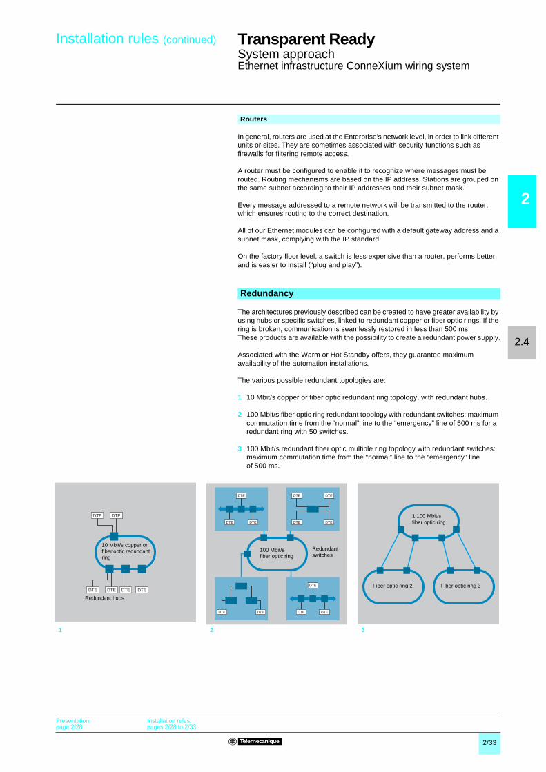
2/33
2
2.4
Installation rules (continued) Transparent Ready 0
System approachEthernet infrastructure ConneXium wiring system
In general, routers are used at the Enterprise's network level, in order to link differentunits or sites. They are sometimes associated with security functions such asfirewalls for filtering remote access.
A router must be configured to enable it to recognize where messages must berouted. Routing mechanisms are based on the IP address. Stations are grouped onthe same subnet according to their IP addresses and their subnet mask.
Every message addressed to a remote network will be transmitted to the router,which ensures routing to the correct destination.
All of our Ethernet modules can be configured with a default gateway address and asubnet mask, complying with the IP standard.
On the factory floor level, a switch is less expensive than a router, performs better,and is easier to install (“plug and play”).
The architectures previously described can be created to have greater availability byusing hubs or specific switches, linked to redundant copper or fiber optic rings. If thering is broken, communication is seamlessly restored in less than 500 ms.These products are available with the possibility to create a redundant power supply.
Associated with the Warm or Hot Standby offers, they guarantee maximumavailability of the automation installations.
The various possible redundant topologies are:
1 10 Mbit/s copper or fiber optic redundant ring topology, with redundant hubs.
2 100 Mbit/s fiber optic ring redundant topology with redundant switches: maximumcommutation time from the “normal” line to the “emergency” line of 500 ms for aredundant ring with 50 switches.
3 100 Mbit/s redundant fiber optic multiple ring topology with redundant switches:maximum commutation time from the “normal” line to the “emergency” lineof 500 ms.
Routers
Redundancy
1 2 3
DTEDTE
DTEDTE DTE DTE
10 Mbit/s copper orfiber optic redundantring
Redundant hubs
DTE
DTEDTE
DTE DTE
DTE
DTEDTE
DTE DTE
DTE DTE
100 Mbit/sfiber optic ring
Redundantswitches
1,100 Mbit/sfiber optic ring
Fiber optic ring 2 Fiber optic ring 3
Presentation:page 2/28
Installation rules:pages 2/28 to 2/33

2/34
2
2.5
Presentation Transparent Ready 0
System approachApplication to electrical distribution
The application of Transparent Ready to electrical distribution power equipment isbased on the concept of the Transparent Ready Power Equipment offer.
This is an optimized architecture in which the Transparent Ready services aremutualized within the EGX gateway, while providing communicating products builtinto the electrical equipment (switchboard) with transparent connectivity for anyModbus client on TCP/IP.
Once the parameters of the EGX gateway have been set, the user therefore has thebenefit of very simple (see below) ready-to-use functions such as:b The display of summary pages on instantaneous measurements and the status ofthe electrical equipment.b The display of detailed electrical data on all circuits (rms current (A), actual power(kW), power factor, active and reactive powers, etc).b The logging of standard data, power, trends, etc.b The display of logs.b Exporting data tables in standard Windows format.
The Web server embedded in the electrical equipment does not interfere with theModbus communication flows from the Modbus clients on the Ethernet network.
The Web Page Generator is a software tool for creating Web pages, designed for theinstaller of the Transparent Ready Power Equipment. Its purpose is the automaticcreation of Web pages, according to the actual configuration of the electricalswitchboard.
It includes a library of electrical distribution and motor control products such as:b PM 800/500 power meters.b Micrologic digital protection relays (Masterpact).b Sepam 2000 and Sepam 20/40/80 digital protection relays.b CM 3000/4000 circuit monitors for measuring and analyzing power quality.
It automatically creates the corresponding Web pages for each of the productsconnected on the Modbus (SL) serial link built into the electrical equipment anddeclared by the installer. It also automatically produces summary pages, providingthe operator with an overall view of the status of his equipment. It also integrates anFTP client in the EGX gateway, which authorizes the immediate downloading of theHTML pages that have been created.The level of knowledge required to carry out these operations has been set at adeliberately low level.
The operating mechanisms of the Web pages created in this way are described onpage 2/42. The HTML pages produced are standard format which can be editedfurther if necessary, using standard word processing or HTML tools.
Transparent Ready Power Equipment
Web Page Generator

2/35
2
2.5
Operation Transparent Ready 0
System approachApplication to electrical distribution
The EGX gateway uses HTML language for serving the Web pages containingdynamic values associated with the products on the Modbus SL link, and is thuscompatible with all Web browsers. This mechanism is totally transparent for the user.
When HTML pages are created, each dynamic data location in the page causes a“<PL>tag” to be inserted which specifies the characteristics of the Modbus servicerequired for finding the value of this variable, as well as presentation data for thisvariable (Modbus function code, Modbus address, register no., LSB order, unit).When the Web page is viewed (action 1, reception of an HTTP request from the Webclient), the EGX gateway analyzes the contents of the requested Web page, detectsany “<PL> tags”, then executes the Modbus services required for reading thedynamic variables (actions 2 and 3), fills in the HTML page accordingly and sends itall back as if it were a static page (action 4). The HTML page is displayed on thebrowser screen.The page is automatically updated by the browser every 5 seconds.
When accessing product data on the Modbus SL link, via Modbus messaging, thegateway has no added value other than translating addresses, encapsulating andunencapsulating Modbus frames, whatever function code is used.The gateway thus provides products on the Modbus SL serial link with the Ethernetpass band and a multi-master operating capability. The latter function is alsoeffective when the Modbus master is connected directly to one of the two Modbus SLports on the EGX gateway (configured this way).
Mechanism for dynamic reading via the Web
1
2
3
4
Web browser
Ethernet (HTTP on IP)
EGX repositoryWeb page server
Modbus SL
Micrologic
PM PM
Sepam
PM
EGX
Transparent access mechanism via Modbus messaging
1
2Modbus frame
Micrologic
PM
Sepam
EGX
PM PM
Modbus TCPEthernet master
Modbus SL
Modbus IP headerModbus frame
Modbus IP frame

2/36
2
2.5
Architecture Transparent Ready 0
System approachModicon Quantum Hot Standby on Ethernet TCP/IP
The Hot Standby option enables the Modicon Quantum automation platform to meetthe needs of the most critical applications in terms of operating safety and availability.The main element of the system is a second PLC referred to as the "Standby",configured to be identical to the "Primary" PLC and in standby mode. The StandbyPLC uses a special high speed fiber optic link to constantly monitor the status of thePrimary PLC.If there is a fault on the Primary PLC, the system automatically controls thechangeover to the Standby PLC. As both PLCs (Primary and Standby)simultaneously scan the same devices distributed on Ethernet TCP/IP using the I/OScanning service, the critical process controlled by these devices is not affected bythe fault in the control system. Likewise, the "IP swapping" function for automaticallytransferring the IP address from the Primary to the Standby makes the changeoverfrom one PLC to the other transparent from the supervision PCs and HMIs.
Two types of Ethernet module can be used in Quantum Hot Standby configurations:140 NOE 771 01 and 140 NOE 771 11.The Ethernet TCP/IP Web and communication services on these modules (Modbusmessaging, Global data, FTP/TFTP, SNMP, HTTP, etc) are available in Hot Standbyconfiguration, apart from the DHCP server providing the FDR (Faulty DeviceReplacement) service.
If there is a changeover from the Primary to the Standby PLC, the "IP swapping"function automatically assigns the IP address of the Ethernet 140 NOE module of thePrimary PLC to the Ethernet 140 NOE module of the Standby PLC making thechangeover transparent from the supervision PCs and HMIs.After having closed the current client and server connections on Ethernet, each 140NOE module sends a UDP changeover message to the 140 NOE module in the otherPLC. The 140 NOE module that sent the message then waits for the response fromthe other 140 NOE module for a "Timeout" of 500 ms. As soon as the message isreceived or after this “Timeout”, the 140 NOE module changes its IP address.Likewise, the changeover is transparent when seen from the process. The mostrecent versions of distributed I/O on Ethernet TCP/IP have a function for maintainingthe status of the outputs if there is a break in communication, thus when there is achangeover from one PLC to the other.To avoid any communication problems, it is recommended that Ethernet 140 NOEmodules in Hot Standby configurations are connected on switches rather than onhubs (for further information on these products see the “Cabling system” section,page 7/2).
Modicon Quantum Hot Standby on Ethernet TCP/IP
INPUT
OUTPUT+–
INPUT
OUTPUT+–
A
B
A
B
INPUT
OUTPUT+–
INPUT
OUTPUT+–
A
B
A
B
INPUT
OUTPUT+–
INPUT
OUTPUT+–
A
B
A
B
INPUT
OUTPUT+–
INPUT
OUTPUT+–
A
B
A
B
INPUT
OUTPUT+–
INPUT
OUTPUT+–
A
B
A
B
INPUT
OUTPUT+–
INPUT
OUTPUT+–
A
B
A
B
INPUT
OUTPUT+–
INPUT
OUTPUT+–
A
B
A
B
INPUT
OUTPUT+–
INPUT
OUTPUT+–
A
B
A
B
IP swapping
Ethernet 100 Mbps
Optical fiber
Ethernet 10/100 Mbps
Embedded Web pages
I/O Scanning
Advantys STB I/OAdvantys STB I/O Momentum I/O Altivar
QuantumQuantum
Switch
Switch
Magelis iPC
Presentation
Operation on changeover

2/37
2
2.5
Functions Transparent Ready 0
System approachUnity Studio software suite
The Unity Studio software suite is the key component required on design officeworkstations used for designing and structuring distributed industrial automationprojects.
Distributed automation projects require the involvement of experts from manydifferent domains (electrical, mechanical and hydraulic engineering, instrumentation,P&ID, communication, HVAC/climate control, etc.) in turn requiring various specialistsoftware applications.
The Unity Studio software suite offers designers of industrial distributed automationprojects the possibility of using all these tools in conjunction.
The objective of the Unity Studio software suite is to:b Provide a unique structural representation of the project shared by experts in allspecific domains.b Increase the productivity of each expert.
Unity Studio is an all-in-one software suite based on Microsoft's graphic design toolVisio 2002 Professional. It is supplied with the following software as standard:b MS Visio 2002.b Unity Studio manager for the management of distributed applications.b Unity Pro XL for the programming of Atrium, Premium and Quantum platforms.b OPC Factory Server (OFS) for accessing and exchanging data in the architecture.b PowerSuite for the setup of Altivar speed drives.b XBT-L1000 for creating Magelis HMI applications.b Microsoft Visual Basic for Applications (VBA) for the development of customizedfunctions.
Unity Studio Manager tools allow you to create direct links with other SchneiderElectric applications, or with third-party software applications.
In addition to this, the Unity Developer's Edition (UDE) software package provides anadvanced open development solution for the programming of user functions and thedevelopment of interactive interfaces with other software applications (programmingin C++, VBA, VBA macros, etc.).
The Unity Studio software suite, using the Visio 2002 Professional graphical engine,enables you to create project views in specific pages:
b Process or machine view, a unique representation shared by all specialistexperts/consultants working on the project (mechanical, hydraulic and electricalengineering, etc.).
b View of the distributed automation architecture, graphical representation ofthe project's automation devices and communication networks.
These views are composed using components classified by specific application(construction, mechanical, hydraulic, electrical engineering, etc.). Visio libraries areenhanced with Schneider components. The creation of graphical views is achievedby dragging and dropping shapes from the libraries to the tabbed pages.
Components, their links and related properties composing the project views areentered once into the graphical views and shared with:v other views,v other Unity Studio suite software, and external software applications.
Unity Studio for the development of a distributed project
“All-in-one” software suite
Project viewsGraphical project views
Graphical view of the process or machine
Graphical view of the distributed automation architecture

2/38
2
2.5
Functions (suite) Transparent Ready 0
System approachUnity Studio software suite
The functional view is a structured tree diagram of the entire set of machine orprocess functions. It is taken from the graphical view of the process or machine.
The topological view is composed using the control architecture graphical view. Thistopological view displays the communication networks and connected devices in afolder structure.
The Unity Studio software suite supplies open libraries of objects that can be re-usedin graphical views:b Visio 2002 Professional libraries.b Telecanique automation product library.Each object can be given its own parameters (type of valve, etc.) by using predefinedproperties, or be enhanced by applying customized properties.
The numerous libraries supplied can be expanded as needed by:b Downloading Visio objects available online, covering all industrial fields (MicrosoftVisio site, product reseller sites or sites specialized in Visio objects).b Creation of objects by the user.
From the Unity Studio project views, it is possible, at any time, to create hyperlinks to:b All document types in .xls, .doc, .pdf formats, etc.b Web pages via a URL.b Software tools for configuration, network diagnostics, production management,etc.
The application view of the Unity Studio software suite is used for centralizedmanagement of information related to the distributed applications.
Project views (continued)
Functional view
Functional view
Topological view
Topological view
Object libraries
Schneider Electricautomation product library
Process library
Adding new objects
Direct-access hyperlinks
Graphical view of the distributed automation architecture
124 3
1 Assignment of an automation application to eachstation in the architecture.
2 Assignment of the settings or programming tool foreach station.
3 Creation and location of files for each station.4 Assignment of functional entities of the process or
the machine to station applications.

2/39
2
2.5
Functions (suite) Transparent Ready 0
System approachUnity Studio software suite
In order to detect any errors as early as possible, Unity Studio analyzes applicationsautomatically. A report signals any possible errors in the form of alerts.
Following the analysis (and after any corrections are made to render the applicationcompliant), performing generation using Unity Studio enables you to create settingsspecific to each station in each corresponding station file.
This check verifies the consistency of project settings with the files of each station.The update operation raises station file settings to the level of the Unity Studioproject. Any modifications made on the stations are checked and reapplied at allother project levels. Existing settings of a station added to the project are updated inUnity Studio (in the event of re-use of an existing station).
The “Global Data” service of Ethernet TCP/IP communication networks ensuresreal-time data exchanges between connected stations. See page 2/18.The Unity Studio Global Data view enables the definition of Global Data distributiongroups and the configuration of settings for published and subscribed stationvariables. During generation at each station level (see page 2/18), this settingconfiguration is saved automatically to station files, thereby ensuring:b Guaranteed consistency of communication between the distributed applications inquestion.b Maximum productivity with respect to station configuration tasks.b Minimized risk of errors.
The Unity Studio software suite is a single publishing resource for the creation ofoverall project documentation including information about the various levels.
The Unity Studio software suite offers a great degree of open development:b Use of diagrams or drawings from CAD tools.b Enhancement of the object catalog (integration of Visio objects, creation of objectsusing XML, etc.).b Establishment of hypertext links to documents and third-party softwareapplications (MES, ERP, Web, configuration tools, maintenance guides, etc.).b Launching of VBA macros.b Import/export at all levels, in standard XML format.
In conjunction with the Unity Studio software suite, Unity Developer's Edition (UDE)enables the development of these custom solutions. It includes, in addition to thedevelopment kit, Unity servers, training, documentation and technical support.This is supplied only after a special contract has been signed with Schneider Electric.Consult your Regional Sales Office.
(1) Defines the Visio 2002 Professional language and the electronical documentation language.
Project analysis operations
Generation for each individual station
Consistency check and update operation
Global Data view
Publication
Application 1
Variable AVariable BVariable C
Subscription
Application 2
PublicationSubscription
Application n
Ethernet TCP/IP
Overall project documentation
Unity Studio software suite open developmentIntegrated open development
Advanced open development, reserved for experienced IT specialists
References
Description Type of license Language(1)
Reference number Weightkg
Unity Studiodevelopmentsoftware suite
Single station French UNY SEW XFU CD10F –English UNY SEW XFU CD10E –
German UNY SEW XFU CD10D –
Spanish UNY SEW XFU CD10S –

2/40
2
2.6
Architecture Transparent Ready 0
System approachIntegration of Transparent Ready products
Transparent Ready industrial products can be integrated into architectures based onthe universal Ethernet TCP/IP network, with no need for any interface. The basicarchitecture below shows the various communication levels and functions requiredby industrial applications to meet data exchange requirements:
Presentation of integration into architectures
1 Company level: Communication between thecontrol system products and the MES(Manufacturing Execution System) or ERP(Enterprise Resource Planning) supervision orinformation systems.
2 Inter-PLC level: Communication to PLCs forprogramming, diagnostics and data transfer, aswell as communication between PLCs forsynchronizing applications.
3 Field level: Communication between PLCs, PCand field devices.
4 Transparent remote communication: Remotecommunication via the Internet, or via telephoneor radio link.
For a complete approach, the followingrequirements must also be taken into account:b System diagnostic servicesb Interoperability with third-party products orprotocolsb Ethernet TCP/IP network security
The various communication requirements of thearchitecture are summarized below in order to:b Present the data exchanges required by eachlevelb Choose the Transparent Ready services andstandard solutions on Ethernet TCP/IP that aremost appropriate for each type of communication
3
1
1
22
3
31
4
4
INPUT
OUTPUT+–
INPUT
OUTPUT+–
A
B
A
B
Modbus Plus/Modbus SLgateway
Partner productThird-partyprotocol product
ATV 58
Momentum
Magelis
Advantys STB
Premium
Quantum Premium
Ethernet 10/100 Mbps
Router
Networkmanager
PC + Internetbrowser
ERP ClientMES ClientInternet
EGX
TSX Micro
Modem
EGX PM
Micrologic
2/41
2
2.6
Selection Transparent Ready 0
System approachIntegration of Transparent Ready products
The requirements at this level are for communication using standard infrastructureand protocols for exchanging high volumes of data with production managementsystems. In some cases, the PLC must be able to adapt to the protocol specific tothe connected system. Response times are not critical.
The Transparent Ready services used are mainly:b HTTP communication, displaying data and sending commands via Web pagesb Data exchange using the OPC (OLE for Process Control) standard via an OFSdata serverb Modbus TCP/IP messagingb TCP Openb E-mail transmissionb Direct publication in relational databases (via the FactoryCast HMI active Webserver)
For this type of communication, it is also necessary to transfer high volumes of datato a group of PLCs.The required response times are in the region of 0.5 to 2 s.
The following Transparent Ready services are used:b Mainly data exchanges using the OPC standard via an OFS data serverb Modbus TCP/IP messagingb TCP Openb HTTP communication integrated in the supervision system, for displaying Webpages from the field devices in supervision pages
A basic HMI (Human/Machine Interface) application must allow maintenancepersonnel to be notified of an event and to view the status of a field device.
The Transparent Ready services used are:b Notification of events by e-mailb Display of data and sending commands via Web pages
When data is sent in point-to-point mode according to PLC programming algorithmsand the required response times are in the region of 200 ms to 1 s, the mainTransparent Ready service to be used is Modbus TCP/IP messaging.
Broadcast communication must enable several applications to be synchronized viareal-time exchanges. In this case a low volume of data is exchanged.The required response times are in the region of 10 to 500 ms.The Transparent Ready Global Data service is particularly suitable for this type ofdata exchange.
1 Company levelCommunication between MES/ERP system and PLCs
Communication between supervision systems and PLCs
Communication between HMI application and PLCs/field devices
2 Inter-PLC levelCommunication for data transfer
Inter-PLC communication for synchronizing applications

2/42
2
2.6
Selection (continued) Transparent Ready 0
System approachIntegration of Transparent Ready products
PLC applications are essentially responsible for controlling the I/O of peripheraldevices. Data must be transferred to all devices quickly, deterministically andrepetitively.The required response times are in the region of 10 to 100 ms.The Transparent Ready I/O Scanner service meets these requirements.
Modbus serial line (Modbus SL) protocol is a world-wide de facto standard. Issimplicity, reliability and low cost enabled it to have today, probably the mostimpotant installed base of communicating industrial products.It is still the best technical/cost compromise for products without needs of high endcommunication performances.
Modbus SL products connection into Transparent Ready architectures with174 CEV300 20 or EGX 200/400MG gateways, is deliberately easy to manage and provides:b Large openness capabilities at low cost, to all Modbus compliant devices of themarket placeb Connection capabilities to existing applicationsb A point of entry into Transparent Ready at an optimised costb Same application layer over a serial line than Ethernet TCP/IP, enablingtransparent message routing.
Mechanism of transparent data access with Modbus messagingIn case of data access to Modbus SL devices with Modbus messaging, the gatewayas no more added value than the adress translation, encapsulated anddesencapsulated Modbus frames, whatever Modbus function code used.This feature is totally transparent for the system, that makes no real difference froman Modbus SL device connected via a gateway and a device directly connected toEthernet TCP/IP. The only difference should be performance.Modbus SL devices connected via a gateway benefit both of Ethernet bandwidth &multi-master feature.
3 Field levelCommunication between PLCs and field devices for controlling theautomation process
Communication with field products Modbus SL
Quantum
Premium Ethernet
Modbus Smart devices
Web browserb
Modbus Smart devices
TR gatewayTR gateway
Existing installation Any Modbus devices
1
2
Modbus SL
TR Modbus
Ethernet TCP
Modbus SL
Modbus IP headerFrame Modbus
Frame Modbus over IP
Frame Modbus
Modbus Smart devices

2/43
2
2.6
Selection (continued) Transparent Ready 0
System approachIntegration of Transparent Ready products
This type of communication is used to configure, monitor and maintain field leveldevices.It must be simple so that less qualified personnel can access first level diagnosticsfrom a standard PC. The most suitable Transparent Ready service for this is thedisplay of diagnostic and customized Web pages. See pages 2/4 to 2/7.All the functions of Magelis XBT F and XBT G graphic display terminals are alsoavailable on Ethernet TCP/IP.The SNMP standard network management protocol can also be used from a networkmanagement station to monitor, control and perform diagnostics on all thecomponents of the Ethernet architecture.
The following table can be used to select the Transparent Ready service accordingto the required type of communication.
Transparent remote communication is possible, with no need for any specialinterface, for programming, diagnostics, data exchanges, viewing and adjustment, ina similar way to connecting to a local area network.
This type of connection is used for remote access to automation products via thePLC programming tool, or by viewing Web pages with a simple Internet browser.Transparent remote access can also be used for the other Transparent Readyservices.
Transparent remote communication on the Internet is possible without the need forany special interfaces. For this, an Internet connection must be available. If not,contact a local Internet service provider.
This type of connection is used for remotely accessing automation products at alower communication cost and over very long distances, using:b The PLC programming toolb A simple Internet browser for viewing the Web pages of the automation productsthat have an embedded Web server
As use of the Internet involves security risks for the system, this type of access mustbe made secure by a Firewall. The use of a VPN (Virtual Private Network) is alsopossible. This type of function must be provided by the Firewall or by an additionaldevice.For further information on remote management services, see “Partnership Program”page 8/3.
Communication between field PCs or operator terminals, PLCs and fielddevices
Choice of Transparent Ready services
Communication Company level 1 Inter-PLC level 2 Field level 3 Seepage
Transparent Ready services Communicationwith MES/ERP
Supervision Basic HMIapplication
Inter-PLCcommunication
Inter-PLCsynchronization
Communicationwithperipherals(I/O)
Diagnostics
Modbus TCP/IP 2/15Web/FactoryCast servers 2/6
I/O Scanning 2/16
Global Data 2/18
SNMP network management 2/21
TCP Open 2/22
OFS server 6/8
4 Transparent remote communicationUsing remote communication
Remote communication on the Internet

2/44
2
2.6
Selection (continued) Transparent Ready 0
System approachIntegration of Transparent Ready products
Transparent point-to-point communication on the telephone network is possibleusing a remote access router or RAS (Remote Access Server). SinceTSX ETZ410/510 Ethernet Web server modules for Modicon TSX Micro PLCsincorporate this function themselves, there is no need to use an externalserver/router.A modem for wired telephone link or GSM is also necessary for telephonecommunication.
As with any connection via a telephone network, access must be made secure byidentification functions, or filtering by a Firewall, automatic callback by the accessserver or VPN server.
For further information on remote telephone connections, please consult yourRegional Sales Office.
Transparent remote communication by radio is also possible on Ethernet TCP/IP,both for communication between products and for links with HMI terminals which canthus be mobile.
Various types of radio technology are compatible with Ethernet TCP/IP:b Bluetoothb Wi-Fib Special wireless industrial systems, based on the 2.4 GHz frequency
Further information on this field, and details of partners supplying these types oftechnology for use with Transparent Ready products, are given on pages 8/2 to 8/9.
Diagnostic services are available from the PLC programming tools, which provide inparticular:b Display of the PLC system statusb Diagnostics of the communication services on Ethernet TCP/IP (Modbus TCP/IPmessaging, I/O Scanning and Global Data services)b Display of the pass band in Ethernet TCP/IP modules (module load level)
Similar or additional services are also available using a simple Internet browser byviewing the PLC Web pages:b “Ready to use” pages for displaying the PLC status, "Rack Viewer" functionb Communication and Ethernet TCP/IP services diagnostics pages (communicationstatistics, I/O Scanning service and Global Data service)b Access to the PLC variables and data via the "Data Editor" functionb "Alarm viewer" function for displaying alarms on Modicon Premium and QuantumPLCsb User Web pages created with the "Graphic Data Editor" function or created usinga standard tool, such as Microsoft Frontpage
In addition to these diagnostics functions there are also the services provided by thestandard SNMP protocol (Simple Network Management Protocol). A networkmanagement station can also monitor, control and perform diagnostics on all thecomponents of the Ethernet architecture and can in particular access the objectsspecific to the Transparent Ready offer contained in the private MIB (ManagementInformation Base) of the PLC communication module.
4 Transparent remote communication (continued)
Remote communication via telephone networks
Remote communication by radio
Other requirements of Ethernet TCP/IP architecturesDiagnostic services
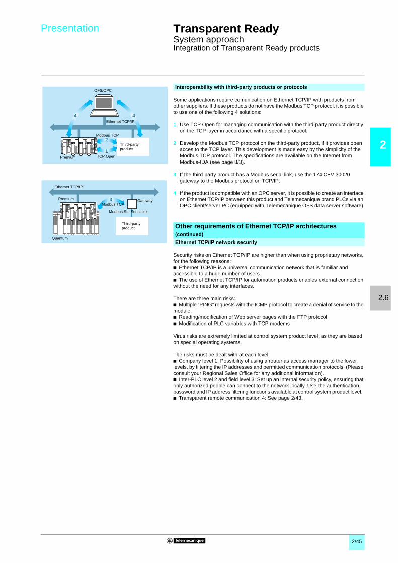
2/45
2
2.6
Presentation Transparent Ready 0
System approachIntegration of Transparent Ready products
Some applications require comunication on Ethernet TCP/IP with products fromother suppliers. If these products do not have the Modbus TCP protocol, it is possibleto use one of the following 4 solutions:
1 Use TCP Open for managing communication with the third-party product directlyon the TCP layer in accordance with a specific protocol.
2 Develop the Modbus TCP protocol on the third-party product, if it provides openacces to the TCP layer. This development is made easy by the simplicity of theModbus TCP protocol. The specifications are available on the Internet fromModbus-IDA (see page 8/3).
3 If the third-party product has a Modbus serial link, use the 174 CEV 30020gateway to the Modbus protocol on TCP/IP.
4 If the product is compatible with an OPC server, it is possible to create an interfaceon Ethernet TCP/IP between this product and Telemecanique brand PLCs via anOPC client/server PC (equipped with Telemecanique OFS data server software).
Security risks on Ethernet TCP/IP are higher than when using proprietary networks,for the following reasons:b Ethernet TCP/IP is a universal communication network that is familiar andaccessible to a huge number of users.b The use of Ethernet TCP/IP for automation products enables external connectionwithout the need for any interfaces.
There are three main risks:b Multiple “PING” requests with the ICMP protocol to create a denial of service to themodule.b Reading/modification of Web server pages with the FTP protocolb Modification of PLC variables with TCP modems
Virus risks are extremely limited at control system product level, as they are basedon special operating systems.
The risks must be dealt with at each level:b Company level 1: Possibility of using a router as access manager to the lowerlevels, by filtering the IP addresses and permitted communication protocols. (Pleaseconsult your Regional Sales Office for any additional information).b Inter-PLC level 2 and field level 3: Set up an internal security policy, ensuring thatonly authorized people can connect to the network locally. Use the authentication,password and IP address filtering functions available at control system product level.b Transparent remote communication 4: See page 2/43.
Interoperability with third-party products or protocols
3
4 4
2
1
Ethernet TCP/IP
Ethernet TCP/IP
OFS/OPC
Premium
Modbus TCP
TCP Open
Third-partyproduct
Modbus TCPPremium Gateway
Third-partyproduct
Quantum
Modbus SL Serial link
Other requirements of Ethernet TCP/IP architectures(continued)Ethernet TCP/IP network security

3

3/1
3
Contents 3 - Field devices 0
3 - Product data sheets
b Modicon Momentum distributed I/O . . . . . . . . . . . . . . . . . . . . . . . . . . . . page 3/2
b Advantys STB distributed I/O . . . . . . . . . . . . . . . . . . . . . . . . . . . . . . . . . page 3/3
b Advantys OTB distributed I/O . . . . . . . . . . . . . . . . . . . . . . . . . . . . . . . . . page 3/4
b ATV 38/58 variable speed drives . . . . . . . . . . . . . . . . . . . . . . . . . . . . . . page 3/5
b Inductel identification system . . . . . . . . . . . . . . . . . . . . . . . . . . . . . . . . . page 3/6
b Modbus and Modbus Plus gateways . . . . . . . . . . . . . . . . . . . . . . . . . . . page 3/6

3/2
3
Product data sheet Transparent Ready 0
Field devicesModicon Momentum distributed I/OEthernet network communication adapters
Momentum I/O bases equipped with 170 ENT 110 0p Ethernet communicationadapters create a distributed I/O system on an Ethernet TCP/IP network.Each I/O base and communicator assembly constitutes a device on the network.Types of base available:b Discrete: inputs or outputs (32 channels max.), mixed I/O (20 channels max.).b Analog: current or voltage inputs or outputs, Pt/Ni thermocouple or temperatureprobe inputs.b Mixed, up to 10 discrete I/O and 10 analog I/O.b Application-specific: 200 kHz 2-channel counter, Modbus port with 9 discrete I/OSensors and preactuators are connected on removable screw or spring terminals.
Ethernet TCP/IP 170 ENT 110 02/01 communication adapters comprise:1 Standard connector for 10BASE-T or 10BASE-T/100BASE-TX interface
depending on model (RJ45).2 Area for identification label (supplied with each I/O base).3 LED status indicators.All the communication adapters can be fitted on any type of I/O base (discrete,analog or application-specific).
Presentation
Description
3 2 1
CharacteristicsType of communicator 170 ENT 110 02 170 ENT 110 01
Transparent Readyservices
Class A10 B20
Standard Web server – “Rack Viewer” access to the productdescription and status and to base unitdiagnostics“Data editor” access to the configurationfunctions and variables
Standard Ethernet TCP/IP communicationservices
Modbus Messaging (read/write data words)
– FDR client for automatic assignment of the IPaddress and network parametersSNMP agent, detection of the product by anSNMP manager
Structure Physical interface RJ45 standard 10BASE-T connector RJ45 standard 10BASE-T/100BASE-TXconnector
Data rate 10 Mbps 10/100 Mbps with automatic recognition
Medium Twisted pair
Ethernetcommunicationadapter
Operating temperature 0…+ 60°C
Relative humidity 5...95% non condensing
Degree of protection IP 20Power supply Via I/O base
I/O bases Discrete inputs c 24 V (16 or 32 channels), a 120 V and 230 V (16 channels)
Discrete solid stateoutputs
c 24 V/0.5 A (16 or 32 channels), a 120 and 230 V/0.5 or 2A (8 or 16 channels)
Discrete solid statemixed I/O
Inputs c 24 V (16 channels) and Outputs c 24 V/0.5 or 2 A (8, 12 or 16 channels)Inputs a 120 V (10 channels) and Outputs a 120 V/0.5 A (8 channels)
Relay mixed I/O Inputs c 24 V (10 channels) and Relay outputs c 20…115 V or Outputs a 24…230 V/2 A (8N/O channels)
Analog inputs Voltage/current (8 or 16 channels), thermocouple/temperature probe (4 channels)Analog outputs - 10 V…+ 10 V, 0…20 mA or - 10 V…+ 10 V, 4…20 mA (4 channels)
Mixed discrete andanalog I/O
4I/2Q analog voltage/current and 4I/2Q c 24V6I/4Q analog 0…10 V and 8I/8Q c 24 V, 6I/4Q analog. - 10…+ 10 V and 8I/8Q c 24 V
Application-specific 200 kHz 2 channel counter, module 6I/3Qa 120 V with 1 RS 485 Modbus port
Conformity to standards UL, CSA, e, FM Class 1 Division 2 UL, CSA, eLED indicators Ethernet network status (LAN Active)
Module status (RUN)Ethernet network status (ST), data rate (10T,100T)Module status (RUN)
ReferencesDescription Transparent Ready
classData rate Reference Weight
kgEthernetcommunicationadapters
A10 10 Mbps 170 ENT 110 02 0.070
B20 10/100 Mbps 170 ENT 110 01 0.070
(1) I/O bases and separate parts: Please consult our “Modicon Momentum automation platform”catalog.
170 ENT 110 02/01

3/3
3
Product data sheet(continued)
Transparent Ready 0
Field devicesAdvantys STB distributed I/OEthernet network interface modules
The Advantys STB distributed I/O solution is an open, modular I/O system. It can beused to design industrial automation islands managed by a master controllerconnected to various buses and networks, including Ethernet TCP/IP. Each islandcomprises a set of modules mounted on a DIN rail to make up one or more segmentsin which the power supplies (logic c 5 V, sensors and preactuators c 24 V ora 115/230 V) are distributed automatically.Sensors and preactuators are connected on removable screw or spring terminals.The Advantys STB configuration software is used to set the parameters of thenumerous I/O module functions (logic of each channel, behavior in the event of ashort-circuit or overload, fallback position, reflex functions, etc)
The STB NIP 2212 Ethernet TCP/IP network interface module has the following onthe front panel:1 A standard connector for 10BASE-T interface (RJ45)2 Two rotary selector switches for addressing nodes on the bus or the network3 A c 24 V external power supply connector for the removable screw-type (STB
XTS 1120) or spring-type (STB XTS 2120) terminals4 An LED display block5 A screw for unlocking the module from the DIN rail6 A slot for an STB XMP 4440 removable memory card7 Cover for access to: a port for connecting the island setup and configuration PC
or an HMI terminal (read/write data), and the Reset buttonOn the right-hand side panel:A bus connector for connecting (via base units) to the power distribution module andto the I/O modules (max. 32 modules on 7 segments).
Presentation
Description
3
2
1 4
56
7
CharacteristicsTransparent Readyservices
Class B20
Standard Web server “Rack Viewer” access to the product description and status and to the island diagnostics“Data editor” access to the configuration functions and variables
Ethernet TCP/IP communicationmanagement service
Modbus messaging (read/write data words)FDR client for automatic assignment of the IP address and network parametersSNMP agent, detection of the product by an SNMP manager
Structure Physical interface RJ45 standard 10BASE-T connector
Data rate 10 Mbps
Medium Twisted pairEthernetcommunicationadapter
Operating temperature 0…+ 60°C
Relative humidity 95% non condensing at 60°C
Degree of protection IP 20
Power supply c 24 V (limits c 19.2…30 V), 400 mA
Max. number of I/O modules 32 per island (16 per segment)
Number of segments 1 primary and 6 extensionsI/O modules Discrete inputs c 24 V (2, 4 or 6 channels), a 115 V and 230 V (2 channels)
Discrete solid stateoutputs
c 24 V/0.5 A (2, 4 or 6 channels), c 24 V/2 A (2 channels), a 115…230 V/2 A (2 channels)
Relay outputs c 24 V or a 115…230 V 2 “C/O”/2 A, 2 “N/C” + “N/O”/7A
Analog inputs - 10 V…+ 10 V, 0…20 mA, multi-range (2 channels)Analog outputs - 10 V…+ 10 V, 0…20 mA (2 channels)
Application-specific 16 Tego Power motor starter inputs, 12 TeSys model U controller-starter inputs
40 kHz 1 channel counter
Conformity to standards IEC/EN 61131-2, UL 508, CSA 1010-1, FM Class 1 Division 2, eLED indicators Ethernet network status (10T ACT, LAN ST)
Module and island status (POWER, RUN, ERROR and TEST)
ReferencesDescription Use Reference Weight
kgEthernet “NIM” network interfacemodulesClass B20
c 24 V power supply STB NIP 2212 0.130
Removable power supply terminals(pack of 10)
Screw STB XTS 1120 0.003
Spring STB XTS 2120 0.003
32 Kb removable memory card Application memorybackup
STX XMP 4440 –
(1) Power distribution modules, I/O modules, bases, configuration software and separate parts:Please consult our “Advantys STB I/O, the open solution” catalog.
STB NIP 2212

3/4
3
Product data sheet(continued)
Transparent Ready 0
Field devicesAdvantys OTB distributed I/OEthernet network interface with discrete I/O
The Advantys OTB distributed I/O solution, which complements the Advantys STBoffer, consists of a compact system (network interface and integrated I/O) with theaddition of Twido I/O expansion modules. Each island has, on a DIN rail:b A network intface module (including Ethernet TCP/IP) with 12 c 24 V inputs, 6relay outputs and 2 solid state outputs c 24 V 0.3 A.b As an extension, up to 7 discrete or analog I/O expansion modules.This structure, created using IP 20 modules, can thus be used to manage 20 to244 I/O per island over a maximum length of 328.7 mm (height 94.5 mm).
The OTB 1E0 DM9LP Ethernet TCP/IP network interface module with integrated I/Ohas the following on the front panel:1 A pivoting door for accessing a standard connector for 10BASE-T/100BASE-TX
physical interface (RJ45).2 An LED display block.3 Screw terminals for the c 24 V sensor power supply and for connecting the input
sensors (with 1 common).4 Screw terminals for connecting the output preactuators (with 4 commons).On the right-hand side panel:A connector for TWD Dpp/App I/O expansion modules (7 modules max.).
Presentation
Description
1
2
34
CharacteristicsTransparent Readyservices
Class A10
Standard Web server None
Standard Ethernet TCP/IP communicationservice
Modbus messaging (read/write data words)
Structure Physical interface RJ45 standard 10BASE-T/10BASE-TX connector
Data rate 10/100 Mbps with automatic recognition
Medium Twisted pair
Ethernetcommunicationadapter
Operating temperature 0…+ 55°C
Relative humidity 30…95% non condensingDegree of protection IP 20
Power supply c 24 V (limits c 20.4…26.4 V)
Inputs 12 inputs c 24 V, 5 and 7.7 mA, 1 common point (positive or negative logic)Connection via removable screw terminals
Outputs 6 a 230 V or c 30 V, 2 A relay outputs, 3 common points (1 x 3, 1 x 2 and 1 x 1)2 c 24 V, 0.3 A transistor outputs, 1 common point (positive logic)Connection via removable screw terminals
Conformity to standards IEC 61131-2, UL 508CSA C22.2 No. 213 (Class 1 Division 2 Groups A, B, C, D), e
LED indicators Controller status (PWR and STAT), I/O (Ip/Qp)Ethernet network status/10 or 100 Mbps data rate (10 T and 100T)
ReferencesDescription No. of discrete I/O Reference Weight
kgEthernet network interface modulec 24 V power supply
Class A10
12 a 24 V inputs6 relay outputs2 c 24 V solid stateoutputs
OTB 1E0 DM9LPr
0.205
r Available soon. Please consult your Regional Sales Office.OTB 1E0 DM9LP
Discrete I/O expansion modulesNumber of channels 8 16 4 I/4 Q 16 I/8 Q
a 120 V inputs TWD DAI 8DT – – –
c 24 V inputs TWD DDI 8DT TWD DDI 16DT TWD DMM 8DRT TWD DMM 24DRF2 A relay outputs TWD DRA 8RT TWD DRA 16RTc 24 V 0.3 A transistor outputs TWD DDO 8TT – – –
Analog I/O expansion moduleNumber of channels 1 2 4 8 2 I/1Q
0…10 V, 0…20 mA inputs – – TWD AMI 4LT TWD AMI 8HT –
Thermocouple/Pt temp. probe inputs – – – TWD ARI 8HT TWD ALM 3LT0…10 V, 4…20 mA outputs TWD AMO 1HT – – – TWD AMM 3HT0…10 V, 4…20 mA inputs – TWD AMI 2HT – –
+/- 0…10 V outputs – TWD AVO 2HT – –For further information, please consult our “Automation and control, automation and relay functions” catalog.

3/5
3
Product data sheet(continued)
Transparent Ready 0
Field equipmentATV 38/58 variable speed drives
Altivar 38 and Altivar 58 variable speed drives are frequency inverters forasynchronous motors, with the following features, depending on the model:
b ATV 38 drive, three phase 380 V…480 V for 0.75 kW…315 kW ratings. This isspecifically designed for fluid management applications in industrial buildings.b ATV 58 drive with the following power supplies:v single phase 200…240 V for 0.37 kW…5.5 kW ratingsv three phase 200…230 V for 1.5 kW…7.5 kW ratingsv three phase 380 V…4500 V for 0.75 kW…75 kW ratingsThis is designed for industrial materials handling, packing and packagingapplications, pumps, compressors and special machines.
Altivar 38/58 drives connect to the Ethernet TCP/IP network via the VW3 A58310communication card.
1 An Ethernet TCP/IP communication card is built into the ATV drive.2 A standard connector for 10BASE-T/100BASE-TX interface (RJ45)
Presentation
ATV 58HU18M2
Description
1
2
CharacteristicsTransparent Readyservices
Class B20
Standard Web services “Altivar Viewer” drive diagnostics“Data editor” access to the configuration, adjustment and signaling functions"Statistics" product status and communication statistics
Ethernet communication managementservices
Modbus messagingFDR client for automatic assignment of the IP address and network parametersSNMP agent, detection of the product by an SNMP manager
Structure Physical interface RJ45 standard 10BASE-T/100BASE-TX connector
Data rate 10/100 Mbps with automatic recognition
Medium Twisted pairDrive Operating temperature - 10…+ 40°C or - 10…+ 50°C depending on model, please consult our "Variable speed drives
and soft starters" catalog
Relative humidity 93% non condensing, no dripping water, conforming to IEC 60068-2-3
Degree of protection That of the drive: IP 21 and IP 41 on upper part
Conformity to standards ISO/IEC 8802.3, ANSI/IEE Std 802.3, UL 508C, CSA C22.2 N14 M95, eDrive standards NF-EN 50178, IEC 61800 class A
LED indicators Collision detection, transmission and reception activity, data rate (10 or 100 Mbps)
ReferencesDescription For drive Reference Weight
kgCommunication cardEthernet Modbus TCP/IP10/100 Mbps
Class B20
ATV 38ATV58/58FAll ratings
VW3 A58310 0.300
VW3 A58310

3/6
3
Product data sheet(continued)
Transparent Ready 0
Inductel identification systemEthernet read/write station
Inductive technology is based on the use of a medium frequency electromagneticsignal (carrier), for contactless transmission between two electronic devices. It isused for identifying products during manufacture and improving the management ofproduct-related data flows.
The system consists of:b Updatable code badges, with decentralized memory (ferroelectric memory orEEPROM), accessible in read and write mode for use with the product to beidentified.b The read/write station with remote antenna, a bidirectional communication devicethat manages the data transmitted between the badge and the processor via theEthernet TCP/IP network.
The XGKS1715503 read/write station is in the form of a dust and damp proof metalbox comprising:1 A 5-way female M12 connector for connection to the antenna (XGLA... or
XGPA…).2 A display block consisting of 5 LEDs indicating the station status.3 A removable cover for accessing the station configuration switches.4 A 20UNF 3 1/2" 3-pin male connector for connecting the c 24 V station power
supply (female connector to be ordered separately).5 An IP 65 shielded base for connection to the Ethernet network.The special connector supplied with the station is used to form a dust and damp proofconnection using any standard RJ45 cable.
This station (210 x 60 x 235), is fixed onto a frame or panel using 4 screws (4 x ∅ 8holes).
Presentation
Read/write station with antenna and updatable code badge
Description1
2
3
45
CharacteristicsTransparent Readyservices
Class A10
Standard Web server No Web server
Standard Ethernet TCP/IP communicationservice
Modbus messaging (read/write I/O words)
Structure Physical interface 10BASE-T/100BASE-TX, standard RJ45 connector with IP 65 shielded base
Data rate 10/100 Mbps with automatic recognition
Medium Double twisted pair
Network interfacemodule controller
Operating temperature 0…+ 50°CRelative humidity 30…95% non condensing
Degree of protection IP 65
Power supply c 24 V (limits c 21…29 V)
External antenna 5-way female M12 connector (antenna/station link 2 m max.)
Communication Requests Modbus TCP/IP 124 words max.
Data rate 500 words/s max. depending on antenna usedConformity to standards UL, e
Electromagnetic interference, level 3 according to IEC 61000-4-2/4-3/4-3
LED indicators On (green), badge present (yellow), badge and communication port faults (red)
Ethernet network activity (RUN, green), collision detection (COL, red), diagnostics (STS,yellow) and fault (ERR, red)
ReferencesDescription Integrated Ethernet
portReference Weight
kgRead/write stationc 24 V power supply
Class A10
10/100 Mbps XGK S1715503 1.120
Antennae, updatable code badges, connection accessories: please consult our “Inductiveidentification system” catalog.
XGK S1715503

4/1
4
Contents 4 - Electrical Distribution products 0
4 - Product data sheets
b MV and LV protection and metering products . . . . . . . . . . . . . . . . . . . . . page 4/2
b Advanced electrical circuit monitors . . . . . . . . . . . . . . . . . . . . . . . . . . . . page 4/3
b PowerLogic SMS electrical power management software . . . . . . . . . . . page 4/4

4/2
4
Product data sheet(continued)
Transparent Ready 0
Electrical distribution productsMV and LV protection and metering products
Merlin Gerin communicating electrical distribution protection and measurementproducts are ideal for integration in Transparent Ready architectures.This range includes in particular:b Sepam series 20, 40 and 80 Medium Voltage (MV) protection relays.b Masterpact Low Voltage (LV) circuit-breakers used with their Micrologic A, P or Hprotection units.b Power Logic power meters (PM), such as the PM500, PM700 and PM800, that canbe used for both MV and LV.b The advanced Power Logic Circuit Monitors (CM), such as the CM2000, CM3000and CM4000.
These products are connected to Ethernet via an EGX gateway or server that isgenerally mutualized for a number of electrical distribution products:
1 An EGX gateway/server with, depending on the model:v EGX 200 gateway if the only requirement is to have transparent connectivity onEthernet (and thus multi-master openness).v EGX 400 server to also have the Web services associated with the aboveproducts, for easy monitoring of the electrical network.2 2 Modbus serial ports for connection to the above product(s).3 A standard connector for 10BASE-T/100BASE-TX (RJ45) interface with, for the
EGX 400 server, a standard connector for 100BASE FX interface.4 A c 24 V power supply.
The EGX also provides Modbus serial link (SL)/Modbus TCP gateway services forall Modbus SL products.The EGX can also take a Modbus master product on one of its ports (configured forthis purpose) that will then have access to the Modbus products on the other port.EGX are specifically designed to withstand harsh thermal or electrical environments.
Presentation
Description
1
234
EGX 200/EGX 400
CharacteristicsType of communicator EGX 200 EGX 400
Transparent Readyservices
Class B10 C10
Standard Web server Configuration of the gateway communication functions
Monitoring/diagnostics pages associated with the products connected downstream
Configurable Web server – Summary Web pages, and ability to recordvariables. Web pages are created using theWPG tool
Ethernet TCP/IP communicationmanagement service
Modbus messaging
SNMP agent, SNTP time synchronization, HTTP protocol, FTP file sharing
Ethernet connection Physical interface 10BASE-T/100BASE-TX (RJ45)
– 100BASE-FXMedium Twisted pair Twisted pair or optical fiber
Modbus SLconnections
Number of ports 2
Types of port Port 1, RS 485 (2 or 4-wire)
Port 2, RS 232 or RS 485 (2 or 4-wire)
Protocol Modbus
Transmission speed 38.4 KbpsRecommended max. number of devices 32 per port, ie. 64 in total
Other characteristics Operating temperature - 30°C to + 80°C
Relative humidity 5…95% non condensing at 40°C
Power supply c 24 V (a 100-240 V socket adapter supplied), 8 W
Conformity to standards cUL (conforming to CSA C22-2 no. 14-M91), UL508, eEnvironmental resistance EN 61000-6-2, EN 61000-4-2/3/4/5/8/11, EN 55022/FCC class AMounting On symmetrical or asymmetrical DIN rail
ReferencesFor Description
Transparent Readyclass
References WeightKg
Sepam,Masterpact/Micrologic,PM, CM or otherModbus SL products
Modbus Ethernetgateway
Class B10 EGX 200MG 0.700
Modbus Ethernetserver
Class C10 EGX 400MG 0.700
Sepam/Masterpact/CMp000/PMp00

4/3
4
Product data sheet(continued)
Transparent Ready 0
Electrical distribution productsAdvanced electrical circuit monitorsCM 3000/CM 4000
CM 3000 and 4000 Circuit Monitors are high-performance monitoring units thatprovide a large number of possibilities.Installed on the incoming feeder, on the Medium Voltage (MV) or Low Voltage (LV)switchboard incoming supply or on sensitive outgoing feeder, the Circuit Monitorsrecord the electrical parameters of the installation. They provide relevant informationfor controlling costs, improving power quality and minimizing production downtime.They offer the possibility of detailed recording of the conditions of any detectedinterference.Depending on the model and the options, they also perform the following:b Detection and recording of voltage dips and jumps which cause productionstoppages on some sensitive processes.b Precise (1 ms) time synchronization by GPS.
They provide current and voltage measurement precisions from 0.04% to 0.1%.
These products are connected to Ethernet via their ECC21 option card.This card also provides an integrated Web gateway/server function to Modbus onEthernet TCP/IP for Modbus Serial Link (SL) communicating products connecteddownstream:
1 ECC 21 Ethernet option card for Circuit Monitor.2 A standard connector for 10BASE-T/100BASE-TX interface (RJ45) with, for the
EGX 400, a 100BASE-FX connector.3 Modbus (SL) serial port for gateway/server function for connecting Modbus
products downstream.The gateway/server function provided by the ECC 21 card is similar to that of theEGX server, but with a lower capacity.
Presentation
CM 3000/CM 4000
Description1
3
2
CharacteristicsType of communicator ECC 21
Transparent Readyservices
Class C10
Configurable Web server Configuration of the CM communication functions and the Modbus TCP gateway function
6 monitoring pages, 5 of which are customizableOne page displays details of the electrical values of the host CMThe other 5 Web pages (created using the WPG tool) can provide displays of the main electricalvalues of the Modbus SL products connected downstream
Ethernet TCP/IP standard communicationmanagement service
Modbus messaging
SNMP agent, SNTP time synchronization, SMTP e-mail notification (transmission according toalarms), HTTP protocol, FTP file sharing
Ethernet connection Physical interface 10BASE-T/100BASE-TX (RJ45)
100BASE-FX
Medium Twisted pair or optical fiber
Modbus SLconnections
Number of ports 1Type of ports RS 485 (2 or 4-wire)
Protocol Modbus
Transmission speed 38.4 Kbps
Recommended max. number of devices 32
Other characteristics Operating temperature - 25°C to + 70°C
Relative humidity 5…95% non condensing at 40°CConformity to standards e, UL508
Environmental resistance EN 61000-6-2, EN 61000-4-2/3/4/5/8/11, EN 55022/FCC class A
ReferencesDescription For Circuit Monitor
metering unitReference Weight
kgEthernet option card
Class C10
CM3000CM4000
ECC21 –
ECC 21
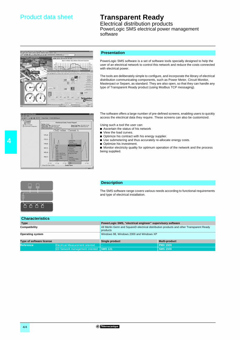
4/4
4
Product data sheet Transparent Ready 0
Electrical distribution productsPowerLogic SMS electrical power managementsoftware
PowerLogic SMS software is a set of software tools specially designed to help theuser of an electrical network to control this network and reduce the costs connectedwith electrical power.
The tools are deliberately simple to configure, and incorporate the library of electricaldistribution communicating components, such as Power Meter, Circuit Monitor,Masterpact or Sepam, as standard. They are also open, so that they can handle anytype of Transparent Ready product (using Modbus TCP messaging).
The software offers a large number of pre-defined screens, enabling users to quicklyaccess the electrical data they require. These screens can also be customized.
Using such a tool the user can:b Ascertain the status of his networkb View the load curves.b Optimize his contract with his energy supplier.b Use submetering and thus accurately re-allocate energy costs.b Optimize his investment.b Monitor electricity quality for optimum operation of the network and the processbeing supplied.
The SMS software range covers various needs according to functional requirementsand type of electrical installation.
Presentation
Description
CharacteristicsType PowerLogic SMS, “electrical engineer” supervisory software
Compatibility All Merlin Gerin and SquareD electrical distribution products and other Transparent Readyproducts
Operating system Windows 98, Windows 2000 and Windows XP
Type of software license Single product Multi-productReference Electrical Measurement oriented – PMX 1500
ED Network management oriented SMS 121 SMS 1500

5/1
5
Contents 5 - Controller and PLCs 0
5 - Product data sheets
b Modicon Momentum M1E processor adapters . . . . . . . . . . . . . . . . . . . . page 5/2
b Twido programmable controller . . . . . . . . . . . . . . . . . . . . . . . . . . . . . . . page 5/3
b Modicon TSX Micro Ethernet modules . . . . . . . . . . . . . . . . . . . . . . . . . . page 5/4
b Modicon Premium platform
v Processors with integrated Ethernet port . . . . . . . . . . . . . . . . . . . . . . page 5/5
v Atrium coprocessors and TCP/IP gateway . . . . . . . . . . . . . . . . . . . . . page 5/6
v Ethernet modules . . . . . . . . . . . . . . . . . . . . . . . . . . . . . . . . . . . . . . . . page 5/7
b Modicon Quantum platform
v Processors with integrated Ethernet port . . . . . . . . . . . . . . . . . . . . . . page 5/8
v Ethernet modules . . . . . . . . . . . . . . . . . . . . . . . . . . . . . . . . . . . . . . . . page 5/9
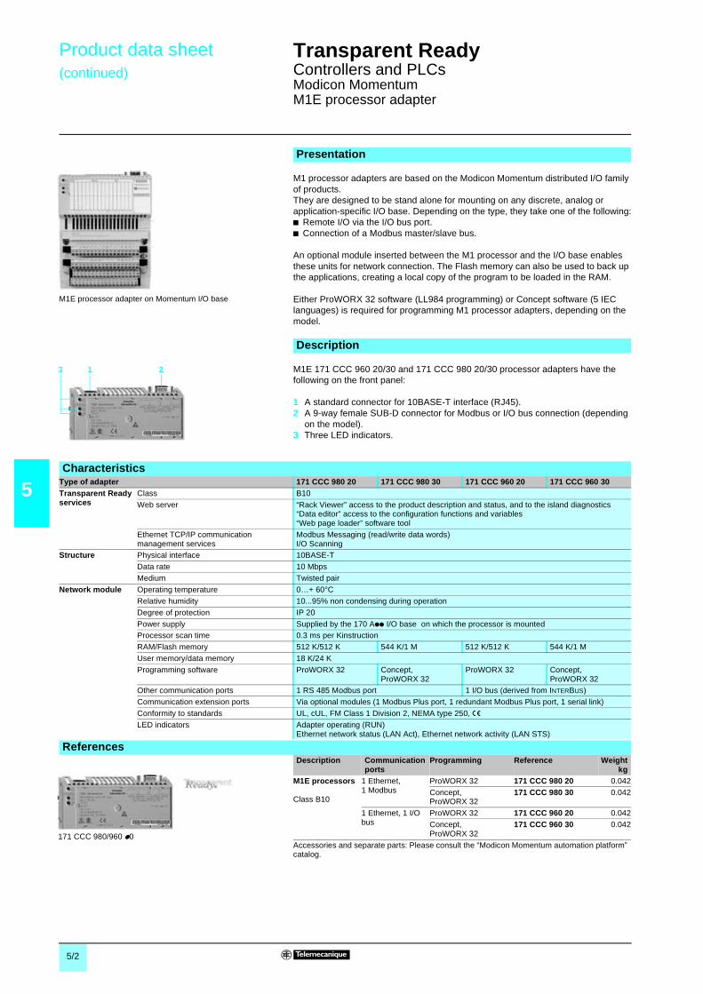
5/2
5
Product data sheet(continued)
Transparent Ready 0
Controllers and PLCsModicon MomentumM1E processor adapter
M1 processor adapters are based on the Modicon Momentum distributed I/O familyof products.They are designed to be stand alone for mounting on any discrete, analog orapplication-specific I/O base. Depending on the type, they take one of the following:b Remote I/O via the I/O bus port.b Connection of a Modbus master/slave bus.
An optional module inserted between the M1 processor and the I/O base enablesthese units for network connection. The Flash memory can also be used to back upthe applications, creating a local copy of the program to be loaded in the RAM.
Either ProWORX 32 software (LL984 programming) or Concept software (5 IEClanguages) is required for programming M1 processor adapters, depending on themodel.
M1E 171 CCC 960 20/30 and 171 CCC 980 20/30 processor adapters have thefollowing on the front panel:
1 A standard connector for 10BASE-T interface (RJ45).2 A 9-way female SUB-D connector for Modbus or I/O bus connection (depending
on the model).3 Three LED indicators.
Presentation
M1E processor adapter on Momentum I/O base
Description
1 23
CharacteristicsType of adapter 171 CCC 980 20 171 CCC 980 30 171 CCC 960 20 171 CCC 960 30Transparent Readyservices
Class B10
Web server “Rack Viewer” access to the product description and status, and to the island diagnostics“Data editor” access to the configuration functions and variables“Web page loader” software tool
Ethernet TCP/IP communicationmanagement services
Modbus Messaging (read/write data words)I/O Scanning
Structure Physical interface 10BASE-T
Data rate 10 Mbps
Medium Twisted pair
Network module Operating temperature 0…+ 60°C
Relative humidity 10...95% non condensing during operation
Degree of protection IP 20
Power supply Supplied by the 170 App I/O base on which the processor is mountedProcessor scan time 0.3 ms per Kinstruction
RAM/Flash memory 512 K/512 K 544 K/1 M 512 K/512 K 544 K/1 M
User memory/data memory 18 K/24 K
Programming software ProWORX 32 Concept,ProWORX 32
ProWORX 32 Concept,ProWORX 32
Other communication ports 1 RS 485 Modbus port 1 I/O bus (derived from INTERBUS)
Communication extension ports Via optional modules (1 Modbus Plus port, 1 redundant Modbus Plus port, 1 serial link)
Conformity to standards UL, cUL, FM Class 1 Division 2, NEMA type 250, eLED indicators Adapter operating (RUN)
Ethernet network status (LAN Act), Ethernet network activity (LAN STS)
ReferencesDescription Communication
portsProgramming Reference Weight
kgM1E processors
Class B10
1 Ethernet,1 Modbus
ProWORX 32 171 CCC 980 20 0.042
Concept,ProWORX 32
171 CCC 980 30 0.042
1 Ethernet, 1 I/Obus
ProWORX 32 171 CCC 960 20 0.042
Concept,ProWORX 32
171 CCC 960 30 0.042
Accessories and separate parts: Please consult the “Modicon Momentum automation platform”catalog.
171 CCC 980/960 p0

5/3
5
Product data sheet(continued)
Transparent Ready 0
Controllers and PLCsTwido compact base
The Twido range of PLCs provides a compact base with integrated Ethernet port.The TWD LCAE 40DRF base is a compact-sized (95 x 90 x 70 mm), “all-in-one”solution. It uses a a 100…240 V power supply and has the following discrete I/O:b 24 c 24 V inputsb 14 relay outputsb 2 c 24 V transistor outputsThis base can take:b Up to 7 I/O expansion modules, thus increasing the I/O capacity to 152 (with screwterminal version) or 264 (with HE 10 connector version).b All Twido range separate parts (memory cartridge or real-time clock, serial linkadaptors, digital display).
The TWD LCAE 40DRF Twido compact PLC base with integrated Ethernet portconsists of:1 An RS 485 serial link port mini-DIN connector (for connecting the programming
terminal).2 A slot for diagnostics/maintenance digital display unit.3 Screw terminals for c 24 V sensor power supply and for connecting the input
sensors (protected by hinged terminal covers).4 A connector for expansion modules (7 modules max. discrete I/O, analog I/O,
AS-Interface bus).5 An LED display block.6 Screw terminals for connecting the output preactuators (protected by hinged
terminal covers).7 Two analog adjustment points.8 A connector for the extension of the RS 232C/RS 485 2nd serial link port.9 Screw terminals for connecting the a 100...240 V power supply.
Accessible from beneath the controller:10A connector for memory cartridge or real-time clock11A standard connector for 10BASE-T/100BASE-TX interface (RJ45)
Presentation
Compact base Twido with digital display
Description
1 2
3
4
5
6
78910 11
CharacteristicsTransparent Readyservices
Class A10
Web server None
Standard Ethernet TCP/IP communicationservices
Modbus messaging (read/write data words)
Structure Physical interface RJ45 standard 10BASE-T/100BASE-TX connector
Data rate 10/100 Mbps with automatic recognition
Medium Twisted pair
Drive Operating temperature - 0…+ 55°CRelative humidity 30...90% non condensing
Degree of protection IP 20
Power supply a 100…240 V, 50/60 Hz (limits a 85…264 V, 47…63 Hz)
c 24 V sensor power supply 250 mA
Inputs 24 c 24 V, 11 and 7 mA, type 1 inputs (positive or negative logic)
Outputs 14 a 230 V or c 30 V, 2 A relay outputs2 c 24 V, 1 A (positive logic) transistor outputs
Counting 2 c 24 V 5 kHz channels, 2 c 24 V 20 kHz channels
Programming TwidoSoft (Ladder language, Instruction List), 3000 instructions (6000 with memory cartridge)
Application memory 3000 instructions (6000 with memory extension cartridge)
Conformity to standards IEC 61131-2, UL 508, UL 1604/CSA C22.2 No. 213 (Class 1 Division 2 Groups A, B, C, D), eand TuV
LED indicators Controller status (PWR, RUN, ERR and STAT), I/O (INp/OUTp)Ethernet network status (LAN ST), 10 or 100 Mbps data rate (L ACT)
ReferencesDescription No. of discrete I/O Reference Weight
kgCompact base with integratedEthernet porta 100…240 V power supply
Class A10
24 a 24 V inputs14 relay outputs2 solid state outputsc 24 V
TWD LCAE 40DRF –
Separate parts, I/O expansion modules, extension modules, prewired system and TwidoSoftprogramming software: Please consult our “Automation and relay functions” catalog.
TWD LCAE 40DRF

5/4
5
Product data sheet(continued)
Transparent Ready 0
Controllers and PLCsModicon TSX MicroEthernet network modules
Modicon TSX Micro is the automation platform designed for small machines andmobile systems. It is flexible and modular, offering connections using removablescrew terminals or HE10 connectors, and is suitable for applications with up to 248discrete I/O.TSX Micro supports the following:b 4 application-specific functions: counting, position control, analog/process controland safety.b AS-Interface, CANopen, Fipio, Modbus and Uni-Telway buses, and Ethernet,Fipway and Modbus Plus networks.TSX Micro offers a choice of supply voltages: c 24 V or a 230 V.
TSX ETZ 410/510 Ethernet modules are autonomous. They are mounted outside theTSX Micro PLC rack, on DIN rails or on AM1-PA pre-slotted plates.TSX ETZ 410/510 modules have the following on the front panel:1 Three LEDs indicating the module status (RUN, ERR, RX/TX).2 The module MAC address (default factory-set address).3 A mini-DIN connector for connection to the terminal port (marked TER).4 An RJ45 connector for Uni-Telway auxiliary connector RS 485 serial link (marked
RS 485).5 A standard RJ45 connector for connection to the Ethernet network (marked
10BASE-T/100BASE-TX).6 A 9-pin male SUB-D connector for RS232 serial link (Modem).7 Screw terminals for connecting the c 24 V external power supply.8 A support plate for fixing the module.
Presentation
TSX 37 20 TSX Micro platform
Description
123
4
5
6
7
8
CharacteristicsType of module TSX ETZ 410 TSX ETZ 510
Transparent Readyservices
Class B20 C20
Standard Web server “Rack Viewer” access to the product description and status and to the PLC diagnostics“Data editor” access to the configuration functions and variables
FactoryCast configurable Web server – Editor for creating Web page mimicsUser Web page hosting (8 Mb available)
Ethernet TCP/IP communicationmanagement services
Modbus messaging (read/write data words)FDR client for automatic assignment of the IP address and network parametersSNMP agent, detection of the device by an SNMP manager
Structure Physical interface RJ45 standard 10BASE-T/100BASE-TX connector
Data rate 10/100 Mbps with automatic recognition
Medium Twisted pair
Network module Operating temperature 0…+ 60°C
Relative humidity 10...95% non condensing during operation
Degree of protection IP 20Power supply c 24 V (limits c 19.2…30 V), 100 mA
Other TCP/IP communication service Uni-TE messaging (client/server requests: 128 bytes in synchronous mode and 1 Kb inasynchronous mode)
Modem connection RS 232C link, PPP protocol, Half or Full-Duplex, 56 Kbps
Conformity to standards IEC/EN 61131-2, UL 508, CSA 1010-1, FM Class 1 Division 2, eLED indicators Ethernet network status (RUN), transmission/reception activity (TX/RX)
Ethernet port fault (ERR)
ReferencesDescription Transparent Ready
classReference Weight
kgAutonomous Ethernet modules forTSX Micro PLCTSX 37 10/20/30
B20 TSX ETZ 410 0.280
C20 TSX ETZ 510 0.280
For further information: Please consult our “Modicon TSX Micro and PL7 software automationplatform” catalog.
TSX ETZ 410/510

5/5
5
Product data sheet(continued)
Transparent Ready 0
Controllers and PLCsModicon PremiumProcessors with integrated Ethernet port
Modicon Premium is the optimized automation platform for complex machines,manufacturing and discrete automation. These processors are open to the latesttechnologies, with built-in universal Ethernet TCP/IP connections. Premium also hasnumerous advanced automation functions (counting, electronic cam, positioncontrol, weighing, control data storage and machine safety).
TSX P57 1634M, TSX P 26pp/2823/36pp/4634/4823/5634M double formatprocessors (1) with built-in Ethernet port include the following on the front panel:1 A display block with 5 LEDs relating to the processor.2 A display block relating to the built-in Ethernet port.3 An 8-way female mini-DIN connector marked TER for connecting a programming
or adjustment terminal.4 A USB connector marked TER for connecting a programming or adjustment
terminal.5 An 8-way female mini-DIN connector marked AUX for connecting an RS 485
peripheral device.6 A standard (RJ45) connector for 10BASE-T/100BASE-TX interface.7 A slot for a PCMCIA memory extension card.8 A slot for a PCMCIA communication or data storage memory extension card.9 A 9-way SUB-D connector (on TSX P57 2823/4823M models) for Fipio bus
manager link.
Presentation
Description
17 2 1 2
3 754
68
9
CharacteristicsType of module Unity Pro software TSX P57 1634M TSX P57 2634M TSX P57 3634M TSX P57 4634M TSX P57 5634M
PL7 Pro software – TSX P57 2p23M TSX P57 3624M TSX P57 4823M –TransparentReadyservices
Class B30
Standard Web server “Rack Viewer” access to the product description and status and to the PLC diagnostics“Data editor” access to the configuration functions and PLC variables
Standard Ethernet TCP/IP communication service Modbus TCP messaging (read/write data words)
Ethernet TCP/IPadvancedcommunicationservices
I/O Scanning Yes (between 64 stations) Yes (128stations)
Global Data Yes
FDR server Automatic assignment of IP address and network parametersSMTP E-mail notification Yes
SNMP network administrator Yes
Pass band management Yes
Structure Physical interface 10BASE-T/100BASE-TX (RJ45)
Data rate 10/100 Mbps with automatic recognition
Medium Twisted pairPremiumprocessor
No. of discrete I/O 512 1024 2048
No. of analog I/O 24 80 128 256 512
No. of application-specific channels 8 24 32 64
Max. no. of network connections (includingintegrated link)
1 3 4 5
Other TCP/IPcommunicationservice
Uni-TE TCP Client/server requests: 128 bytes in synchronous mode and 1 Kb in asynchronous mode
X-Way Yes
Operating temperature 0…+ 60°CRelative humidity 10...95% non condensing during operation
Degree of protection IP 20
Power supply Via the power supply of the rack supporting the processor
Conformity to standards IEC/EN 61131-2, UL 508, CSA 1010-1, FM Class 1 Division 2 Group A/B/C/D, eLED indicators Ethernet network status (RUN), transmission/reception activity (TX/RX)
Collision detection (COL), Ethernet link diagnostics (STS), Ethernet port fault (ERR)5 LEDs specific to the operation of the processor (RUN, ERR, I/O, TER and FIP)
ReferencesDescription Discrete I/O
Analog I/OApp-sp. chann.
Reference Weightkg
Unity software PL7 softwareProcessors withintegratedEthernet link
Class B30
512 / 24 / 8 TSX P57 1634M – 0.042
1024 / 80 / 24 TSX P57 2634M TSX P57 2623M 0.042
– TSX P57 2823M (2)
1024 / 128 / 32 TSX P57 3634M TSX P57 3623M 0.042
2048 / 256 / 64 TSX P57 4634M TSX P57 4823M (2) 0.0422048 / 512 / 64 TSX P57 5634M –
(1) Except TSX P57 1634M processor, single format.(2) Also has an integrated Fipio bus manager link.
For further information: Please consult our “Modicon Premium and PL7 software automationplatform” or “Modicon Premium and Unity software automation platform” catalogs.TSX P57 4634/5634M TSX P57 26/28/36/48ppM

5/6
5
Product data sheet(continued)
Transparent Ready 0
Controllers and PLCsModicon AtriumCoprocessors and TCP/IP gateway
The Atrium coprocessor (PCI bus card), combined with a Magelis iPC industrial PC,provides a PC with a built-in PLC and supervisory software. This type of configurationis designed for installations that require a high level of interaction between theautomation functions and the HMI applications.The software gateway enables Atrium PLCs to communicate using Modbus (orUni-TE) Ethernet TCP/IP via the integrated Ethernet port in the industrial PC.
TSX PCI 57 204/354M coprocessors occupy two consecutive slots on the PC PCIbus but only use one electrically. They comprise:b On the faceplate:1 A slot for a PCMCIA communication or data storage memory extension card.2 A 9-way female SUB-D connector for connecting Bus X to the first Premium rack
supporting the I/O modules and application-specific modules.3 An 8-way female mini-DIN connector marked TER for connecting a programming
terminal.4 An ERR LED (coprocessor or embedded equipment fault).5 A 9-pin male SUB-D connector (on TSX PCI 57 354M model) for Fipio bus
manager communication.b On the card, component side:v 4 or 5 LEDs indicating the operating status.v A slot for the coprocessor internal RAM backup battery.v A slot for a PCMCIA memory extension card.
The TCP/X-Way software gateway performs 2 main functions for Atriumcoprocessors:b Communication using the Modbus (or Uni-TE) TCP/IP protocol via the EthernetTCP/IP card integrated in the PC.b Data exchange in both directions with remote stations via the telephone modem inthe PC.This software interfaces with the Atrium coprocessor PCIway driver andautomatically routes messages. The most common configurations are:v Via Ethernet network (diagram opposite). Access is made secure by checkingincoming IP addresses, in a similar way to the Premium PLC Ethernet TSX ETY 4103module. The Global Data and I/O Scanning services are not supported.v Via modem link. Incoming calls are checked via the standard Windows passwordchecking mechanisms. In addition to remote access with Unity Pro, the TCP/IPgateway enables communication with other stations that can be connected to a localEthernet network (RAS (Remote Access Server) function).
Presentation
Description of the Atrium coprocessor
2
1
3
5
4
1 2
3
SCADAOFS server
Ethernet TCP/IP
PC
Premium
Quantum
ModbusUni-TE
1 Atrium coprocessor2 Ethernet TCP/IP card or integrated port3 TCP/X-Way software gateway
Description of the TCP/IP gateway
CharacteristicsType of module Unity Pro software TSX PCI 57 204M TSX PCI 57 454M
Transparent Readyservices
Class A10
Standard Web server NoneStandard Ethernet TCP/IP communicationservice
Modbus TCP messaging (read/write data words)
Structure That of the Ethernet link integrated in the host PC
Atrium coprocessor See characteristics of the Premiumprocessor
TSX P57 2pppM, page 5/5 TSX P57 3pppM, page 5/5
ReferencesDescription Discrete I/O
Analog I/OApp-sp. chann.
Type of license Reference Weightkg
Coprocessors
Class A10
1024 / 80 / 24 – TSX PCI 57 204M 0.3102048 / 256 / 64 – TSX PCI 57 454M 0.340
TCP/IP gatewaysoftware
– Single station TLX CD GTW 10M –
10 stations TLX CD10 GTW 10M –
200 stations TLX CDUNT GTW 10M –
TSX PCI 57 204M TSX PCI 57 454M

5/7
5
Product data sheet(continued)
Transparent Ready 0
Controllers and PLCsModicon PremiumEthernet network module
TSX ETY ppp modules are single format modules which are installed in a rack sloton Modicon Premium PLC stations or Modicon Atrium coprocessors. A configurationcan take from 1 to 4 network modules, depending on the type of processor.TSX ETY 110/110 WS/4103/5103 Ethernet modules route X-Way and Uni-TEmessages transparently from a TCP/IP network to an X-Way network and vice versa.
The front panel of TSX ETY ppp modules comprises:1 A display block indicating the state of the module.2 A standard connector for 100BASE-TX and/or /100BASE-T interface (RJ45)
depending on the model.3 A standard connector for 10BASE5 interface (AUI).4 Four thumbwheels for defining the station number and network number.
Presentation
Description
1
2
3
4
CharacteristicsType of module TSX ETY 110 TSX ETY 110 WS TSX ETY 4103 TSX ETY 5103 TSX WMY 100M
TransparentReadyservices
Class A10 C10 B30 C30 D10
Standard Web server – “Rack Viewer” access to the product description and status and to the PLCdiagnostics“Data editor” access to the configuration functions and variables
FactoryCast configurable Web server – Yes – Yes
User Web pages (available size) – Yes (1.4 Mb) – Yes (8 Mb)
FactoryCast HMI active Web server – Yes (1)Standard Ethernet TCP/IP communicationservices
Modbus TCP messaging (read/write data words)
Ethernet TCP/IPadvancedcommunicationservices
I/O Scanning – Yes (between 64 stations) –
Global Data – Yes –
FDR server – Automatic assignment of IP addressand network parameters
–
NTP time synchronization – Yes –
SMTP e-mail notification – Yes –
SNMP network administrator SNMP agent
TCP Open – Option – Option –Pass band management – Yes –
Structure Physical interface 10BASE-T (RJ45)/10BASE5 (AUI) 10BASE-T/100BASE-TX (RJ45)
Data rate 10 Mbps 10/100 Mbps with automatic recognition
Medium Twisted pair/AUI cable Twisted pair
Networkmodule
Operating temperature 0…+ 60°C
Relative humidity 10...95% non condensing during operation
Degree of protection IP 20Power supply Via the power supply of the rack supporting the processor
Other TCP/IPcommunicationservice
Uni-TE TCP Client/server requests: 128 bytes in synchronous mode and 1 Kb inasynchronous mode
–
Ethway/X-Way Uni-TE, common words –
Conformity to standards IEC/EN 61131-2, UL 508, CSA 1010-1, FM Class 1 Division 2 Group A/B/C/D, eLED indicators Ethernet network status (RUN), transmission/reception activity (TX/RX)
Collision detection (COL), Ethernet port fault (ERR)
ReferencesDescription Data rate Transparent Ready
classReference Weight
kgEthernet TCP/IPmodules
10 Mbps A10 TSX ETY 110 0.370
C10 TSX ETY 110 WS 0.370
10/100 Mbps B30 TSX ETY 4103 0.340
C30 TSX ETY 5103 0.340D10 TSX WMY 100 0.340
FactoryCast HMIsoftware
HMI application development anddebugging in TSX WMY 100
TLX CD FCHMI V1M –
TCP Opensoftware (2)
SDKC, C language development TLX LSDKC PL741M –
TCP Open function block library TLX CD TCPA33E –
(1) Database management, arithmetic and logic calculations, automatic e-mail transmission onprocess event, connection to relational databases.
(2) With TSX ETY 110 WS and TSX ETY 5103 modules.
For further information: Please consult our “Modicon Premium and PL7 software automationplatform” or “Modicon Premium and Unity software automation platform” catalogs.
TSX ETY 110/110 WS TSX ETY p103/WMY 100

5/8
5
Product data sheet(continued)
Transparent Ready 0
Controllers and PLCsModicon QuantumProcessors with integrated Ethernet port
Equipped with a high performance processor, Modicon Quantum is optimized forprocess control and high-availability needs.The Quantum platform meets the requirements of the agribusiness, pharmaceutical,metallurgy, chemical-petrochemical and energy-infrastructure sectors.
The new Quantum processors are open to the latest technologies with built-InEthernet TCP/IP connections, data storage, and a LCD keypad for local monitoring.
The 140 CPU 651 50 and 140 CPU 651 60 processors have the following on the frontpanel:1 An LCD display cover, providing access to:v A key switch for locking system operations that may be requested and all thepermitted parameters that may be modified via the LCD display (2) and 5-buttonkeypad (3).v A slot for the backup battery.v A “Restart” pushbutton.2 An LCD display (2 lines of 16 characters) with brightness and contrast controls.3 A 5-button keypad with LEDs (ESC, ENTER, MOD, ÎI, =>).4 An RJ45 connector for connection to the Modbus bus.5 A type B female USB connector for connecting the programming PC.6 A 9-way female SUB-D connector for connection to the Modbus Plus network.7 Two slots for PCMCIA memory extension cards.8 Two LEDS marked COM and ERR.9 An RJ45 connector for connection to the Ethernet network.
Presentation
Description
1
2
345
6
7
9
8
CharacteristicsType of module Unity Pro software 140 CPU 651 50 140 CPU 651 60
TransparentReadyservices
Class B30
Standard Web server “Rack Viewer” access to the product description and status and to the PLC diagnostics“Data editor” access to the configuration functions and PLC variables
Standard Ethernet TCP/IP communicationservice
Modbus TCP messaging (read/write data words)
Ethernet TCP/IPadvancedcommunicationservices
I/O Scanning Yes (between 128 stations)
Global Data Yes
FDR client Automatic assignment of IP address and network parameters
SMTP e-mail notification YesSNMP network administrator Yes
Pass band management Yes
Structure Physical interface 10BASE-T/100BASE-TX (RJ45)
Data rate 10/100 Mbps with automatic recognition
Medium Twisted pair
Quantumprocessor
No. of discrete I/O Local: 26 slots, decentralized: 31744 I/31744 Q, distributed: 8000 I/8000 Q/networkNo. of analog I/O Local: 26 slots, decentralized: 1984 I/31984 Q, distributed: 500 I/500 Q/network
Max. no. of communication modules 6 in local rack
Max. memorycapacities
Program 7168 Kb
Localized/non-localized data 512 Kb 1024 Kb (768 Kb with no PCMCIA card)
Data storage 8192 Kb
Operating temperature 0…+ 60°CRelative humidity 10...95% non condensing during operation
Degree of protection IP 20
Power supply Via the power supply of the rack supporting the processor
Conformity to standards UL 508, cUL, CSA 22.2-142, FM Class 1 Division 2, eLED indicators Activity on the Ethernet port (COM), collision detection (ERR)
ReferencesDescription Processor
clockfrequency
Program/datacapacity (1)
Reference Weightkg
Processors withintegratedEthernet linkClass B30
166 MHz 7168 Kb/512 Kb 140 CPU 651 50 –
266 MHz 7168 Kb/1024 Kb 140 CPU 651 60 –
(1) With PCMCIA card.For further information: Please consult our “Modicon Quantum and Unity software automationplatform” catalog.140 CPU 651 50/60

5/9
5
Product data sheet(continued)
Transparent Ready 0
Modicon QuantumEthernet network modules
Ethernet 140 NOE 771 p1/NWM 100 00 Ethernet network modules are single formatmodules for installing in the local rack slots of a Modicon Quantum PLCconfiguration.A configuration can take from 2 to 6 application-specific modules, including networkmodules, depending on the type of processor.
The front panel of TCP/IP 140 NOE 771 01/771 11 and 140 NWM10000 Ethernetmodules comprises:
1 A display block, which indicates the module status and the transmission status onthe network.
2 A hinged cover for access to:v A standard (RJ45) connector for 10BASE-T/100BASE-TX interface.v A connector for 100BASE-FX optical interface (MT-RJ).
Presentation
Description1
2
CharacteristicsType of module 140 NOE 771 01 140 NOE 771 11 140 NWM 100 00
TransparentReady services
Class B30 C30 D10
Standard Web server “Rack Viewer” access to the product description and status and to the PLC diagnostics“Data editor” access to the configuration functions and variables
FactoryCastconfigurableWeb server
Editor for creating Web pagemimics
– Yes
User Web page hosting(available size)
– Yes (8 Mb)
FactoryCast HMI active Web server – Yes (1)
Standard Ethernet TCP/IP communicationservices
Modbus TCP messaging (read/write data words)
Ethernet TCP/IPadvancedcommunicationservices
I/O Scanning Yes (between 128 stations) –
Global Data Yes
FDR server Automatic assignment of IP address and network parameters –
NTP time synchronization Yes –SMTP e-mail notification Yes –
SNMP network administrator Yes SNMP agent
Pass band management Yes –
Redundancy service Compatible with Hot Standby redundant architecture –
Structure Physical interface 10BASE-T/100BASE-TX (RJ45) or 100BASE-FX (MT/RJ)
Data rate 10/100 MbpsMedium Twisted pair/optical fiber
Networkmodule
Operating temperature 0…+ 60°C
Relative humidity 10...95% non condensing during operation
Degree of protection IP 20
Power supply Via the power supply of the rack supporting the processor
Conformity to standards UL 508, cUL, CSA 22.2-142, FM Class 1 Division 2, eLED indicators Rack operational (Active), module ready (Ready), network active (Link)
Ethernet network status (Run), download mode (Kernel), Full-duplex mode (Fduplex)Transmission/reception activity (TxAct/RxAct), 10 Mbps or 100 Mbps data rate (10MB/100MB)Collision detection (Coll), Ethernet module fault (Fault)
(1) Database management, arithmetic and logic calculations, automatic e-mail transmission onprocess event, connection to relational databases.
ReferencesDescription Data rate Transparent Ready
classReference Weight
kgEthernet TCP/IPmodules
10/100 Mbps B30 140 NOE 771 01 0.345
C30 140 NOE 771 11 0.345
D10 140 NWM 100 00 0.345
For further information: Please consult our “Modicon Quantum automation platform” or “ModiconQuantum and Unity software automation platform” catalogs.
140 NOE 771 p1/NWM 100 00

6

6/1
6
Contents 6 - Human/Machine Interfaceproducts 0
6 - Product data sheets
b Magelis XBT graphic terminals . . . . . . . . . . . . . . . . . . . . . . . . . . . . . . . . page 6/2
b Magelis iPC industrial PCs
v Smart and Compact . . . . . . . . . . . . . . . . . . . . . . . . . . . . . . . . . . . . . . page 6/3
v Modular . . . . . . . . . . . . . . . . . . . . . . . . . . . . . . . . . . . . . . . . . . . . . . . . page 6/4
b FactoryCast HMI application development software . . . . . . . . . . . . . . . page 6/5
b Vijeo Look SCADA software . . . . . . . . . . . . . . . . . . . . . . . . . . . . . . . . . . page 6/6
b Monitor V7.2 SCADA software . . . . . . . . . . . . . . . . . . . . . . . . . . . . . . . . page 6/7
b OFS data server software . . . . . . . . . . . . . . . . . . . . . . . . . . . . . . . . . . . . page 6/8
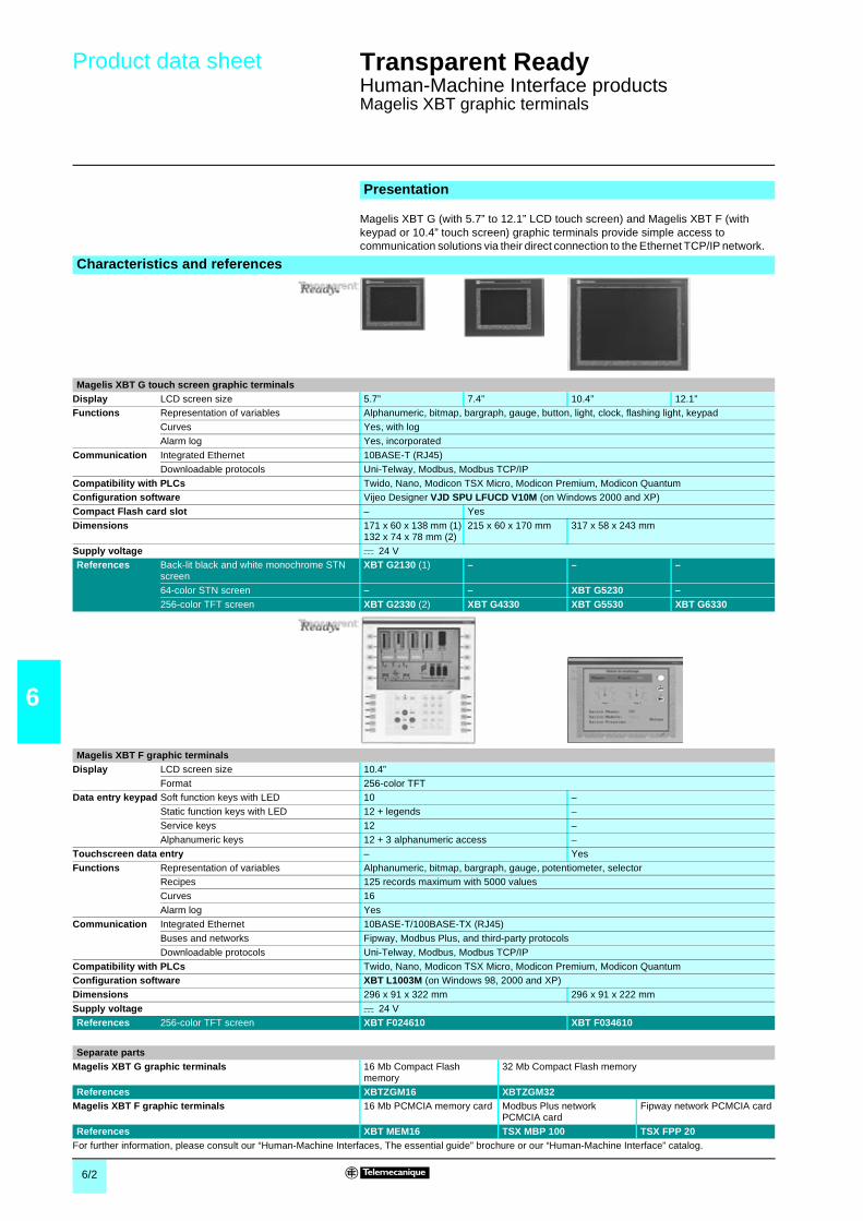
6/2
6
Product data sheet Transparent Ready 0
Human-Machine Interface productsMagelis XBT graphic terminals
Magelis XBT G (with 5.7” to 12.1” LCD touch screen) and Magelis XBT F (withkeypad or 10.4” touch screen) graphic terminals provide simple access tocommunication solutions via their direct connection to the Ethernet TCP/IP network.
Presentation
Characteristics and references
Magelis XBT G touch screen graphic terminalsDisplay LCD screen size 5.7” 7.4” 10.4” 12.1”Functions Representation of variables Alphanumeric, bitmap, bargraph, gauge, button, light, clock, flashing light, keypad
Curves Yes, with log
Alarm log Yes, incorporated
Communication Integrated Ethernet 10BASE-T (RJ45)
Downloadable protocols Uni-Telway, Modbus, Modbus TCP/IP
Compatibility with PLCs Twido, Nano, Modicon TSX Micro, Modicon Premium, Modicon QuantumConfiguration software Vijeo Designer VJD SPU LFUCD V10M (on Windows 2000 and XP)
Compact Flash card slot – Yes
Dimensions 171 x 60 x 138 mm (1)132 x 74 x 78 mm (2)
215 x 60 x 170 mm 317 x 58 x 243 mm
Supply voltage c 24 VReferences Back-lit black and white monochrome STN
screenXBT G2130 (1) – – –
64-color STN screen – – XBT G5230 –256-color TFT screen XBT G2330 (2) XBT G4330 XBT G5530 XBT G6330
Magelis XBT F graphic terminalsDisplay LCD screen size 10.4”
Format 256-color TFTData entry keypad Soft function keys with LED 10 –
Static function keys with LED 12 + legends –
Service keys 12 –
Alphanumeric keys 12 + 3 alphanumeric access –
Touchscreen data entry – Yes
Functions Representation of variables Alphanumeric, bitmap, bargraph, gauge, potentiometer, selectorRecipes 125 records maximum with 5000 values
Curves 16
Alarm log Yes
Communication Integrated Ethernet 10BASE-T/100BASE-TX (RJ45)
Buses and networks Fipway, Modbus Plus, and third-party protocols
Downloadable protocols Uni-Telway, Modbus, Modbus TCP/IP
Compatibility with PLCs Twido, Nano, Modicon TSX Micro, Modicon Premium, Modicon QuantumConfiguration software XBT L1003M (on Windows 98, 2000 and XP)
Dimensions 296 x 91 x 322 mm 296 x 91 x 222 mm
Supply voltage c 24 V
References 256-color TFT screen XBT F024610 XBT F034610
Separate partsMagelis XBT G graphic terminals 16 Mb Compact Flash
memory32 Mb Compact Flash memory
References XBTZGM16 XBTZGM32Magelis XBT F graphic terminals 16 Mb PCMCIA memory card Modbus Plus network
PCMCIA cardFipway network PCMCIA card
References XBT MEM16 TSX MBP 100 TSX FPP 20For further information, please consult our “Human-Machine Interfaces, The essential guide” brochure or our “Human-Machine Interface” catalog.

6/3
6
Product data sheet Transparent Ready 0
Human-Machine Interface productsMagelis Smart iPC/Compact iPC industrial PCs
Magelis Smart iPC and Compact iPC industrial PCs are characterized by theircompact size, their simplicity and their speed of setup. They use the latest EthernetTCP/IP and Web client connection technologies.
Smart iPC and Compact iPC industrial PCs have a 15” TFT active matrix back-litcolor LCD touchscreen. They include:b An Ethernet 10BASE-T/100BASE-TX port (RJ45 connector)b Web browser software tools (Internet/Intranet)Also included, depending on the model:b Smart iPC, a hardened PC with no vulnerable components (hard disk, CD-ROMdrive, etc.), includes:v Windows XPe operating systemv A client for Windows Terminal Services client/server architecturesv Software (Readers) for reading Word (.doc), Excel (.xls), PowerPoint (.ppt) andAcrobat (.pdf) files.b Compact iPC, an industrial PC with a hard disk (> 20 MB) and CD-ROM and floppydisk drives.
Presentation
Characteristics and references
Compact industrials PCs Smart iPC Compact iPCDisplay Size 15” active matrix XGA (1024 x 768)
Format TFT active matrix back-lit color LCD (262,144 colors)
Data entry Via touchscreen
Processor Format VIA Intel Pentium 4 Mobile
Frequency 667 MHz 1.7 GHzInternal hard disk – u 20 Gb IDE, 2½”
RAM 250 Mb expandable up to 512 Mb 250 Mb expandable to 512 Mb (1 memory slot max.)
CD-ROM drive – Yes, 24x
Expansion slots 2 PCMCIA slots–
1 PCI bus slot, 2 PCMCIA slots1 Compact Flash slot
Ethernet TCP/IP network 1 x 10BASE-T/100BASE-TX (RJ45)
Operating system Windows Xpe integrated Windows 2000 preinstalled
I/O ports 2 x USB, 1 x COM1, 1 x COM2,1 x LPT1 (parallel), 1 x PS/2keyboard
2 x USB, 1 x COM1, 1 x COM2, 1 x LPT1 (parallel), 1 x PS/2keyboard and 1 x PS/2 mouse
On front panel – 1 x USB
Fixing Fixings included with each product for mounting on panel or enclosure door
Dimensions W x D x H 395 x 62 x 294 mm 395 x 100 x 294 mm
Power supply 24 VDC 115…230 VAC
References MPC ST5 2NDJ 00T MPC KT5 2NAA 00N MPC KT5 5NAA 00N
Compact iPC and Vijeo Look software combined offerType of processor VIA 667 MHz Pentium 4 Mobile 1.7 GHz
Vijeo Look supervisory software(1) Run Time (RT) Build Time/Run Time (BT/RT)References MPC KT5 2NAA 00A MPC KT5 5NAA 00A MPC KT5 5NAA 00B
Separate partsDescription 512 Mb Compact Flash
memory512 Mb memory extension forVIA 667 MHz
512 Mb memory extension forPentium 4 Mobile 1.7 GHz
References MPC YN0 0CFE 00N MPC YN0 2RAM 512 MPC YN0 5RAM 512
(1) See page 6/5.
For further information, please consult our “Human-Machine Interface, The essential guide” brochure or our “Human-Machine Interface” catalog.

6/4
6
Product data sheet Transparent Ready 0
Human-Machine Interface productsMagelis Modular iPC industrial PCs
The modularity and flexibility of the Magelis Modular iPC range enables you tochoose the ideal solution for your HMI requirements on a PC base, with easyupgrading and fast maintenance:b IP 65 front panels: 12" or 15" color TFT LCD screen, with or without touchscreencapability, and with or without QWERTY keyboard.b Control boxes, with varying power and expansion capabilities.As standard, the Control boxes include an Ethernet 10/100 Mbps port, two USBports, the various standard serial and parallel ports, and up to 6 PCI/ISA bus slots.
Presentation
Characteristics and references
Screens for Modular iPC industrial PCs (any screen can be used with any type of Control box)
Display LCD screen size TFT active matrix back-lit (262,144 colors)Data entry By Keypad Keypad and touchscreen Touchscreen
Alphanumeric keys 70 standard IBM keys –
User function keys 2 x 10 keys –
Input/output ports and device on front panel 1 IrDA infrared port, 1 PS/2 port for keyboard/mouse and pointing device
Combination With any of the Control boxes listed below
Dimensions Screen size 12” 410 x 52.7 x 330 mm 380 x 52.7 x 330 mmScreen size 15” 480 x 52.7 x 370 mm 460 x 52.7 x 340 mm
References Screen size 12” MPC NA2 0NNN 00N MPC NB2 0NNN 00N MPC NT2 0NNN 00NScreen size 15” MPC NA5 0NNN 00N MPC NB5 0NNN 00N MPC NT5 0NNN 00N
Control boxes Small Medium LargeProcessor Intel Celeron 566 MHz Intel Pentium III
850 MHzIntel Celeron566 MHz
Intel Pentium III850 MHz
Internal hard disk > 20 Gb > 20 Gb, removable
RAM SDRAM 256 Mb, expandable to 512 Mb (2 memory slots maximum)
CD-ROM drive Optional Removable, 24x
Floppy disk drive 3½”, 1.44 Mb 3½”, 1.44 Mb, removable
Expansion slots – 3 slots (1 ISA bus, 1 PCI bus and1 PCI/ISA bus)
6 slots (2 ISA bus, 3 PCI bus and1 PCI/ISA bus)
Integrated Ethernet TCP/IP port 1 x 10BASE-T/100BASE-TX (RJ45)
I/O ports 2 x USB, 2 x COM, 1 x parallel, 1 x external VGA screen, 1 x PS/2 keyboard, 1 x PS/2 pointingdevice
Combination With any of the above types of screen or for use on its own (in this case, use theMPC NP0 0NNN 00N mounting panel)
Operating system Windows 2000 or Windows XPe pre-installed
Dimensions 310x94.2 x310mm 310 x 184.5 x 310 mm 310 x 258 x 310 mm
References a 115…230 V power supply MPC AN02NAp 00N
MPC BN02NAp 00N
MPC CN05NAp 00N
MPC CN02NAp 00N
MPC CN05NAp 00N
c 24 V power supply MPC AN02NDp 00N
MPC BN02NDp 00N
MPC BN05NDp 00N
MPC CN02NDp 00N
MPC CN05NDp 00N
Replace p with A for Windows 2000, and with J for Windows XPeModular Magelis iPC-Vijeo Look software combined offers Small Medium Large
Processor Intel Celeron, 566 MHz
Vijeo Look supervisory software (see page 6/5) Run Time (RT) Build Time/Run Time (BT/RT)
References a 115…230 V power supply MPC AN02NAA 00A
MPC BN0 2NAA 00B MPC BN0 2NAA 00C
Separate partsDescription RAM memory extension Front panel remote connection kit
(with 10 m cable)64 MB 128 MB 256 MB
References a 115…230 V power supply MPC YN00RAM 064
MPC YN00RAM 128
MPC YN00RAM 256
MPC YN0 0RFP KIT
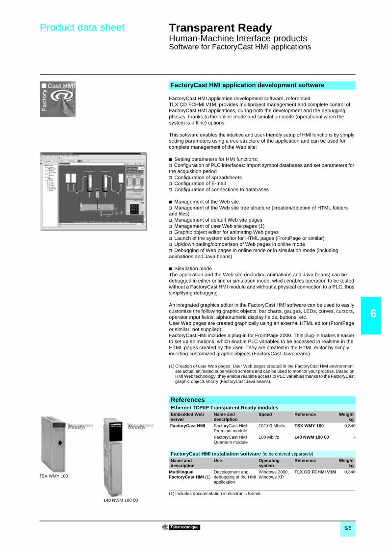
6/5
6
Product data sheet Transparent Ready 0
Human-Machine Interface productsSoftware for FactoryCast HMI applications
FactoryCast HMI application development software, referencedTLX CD FCHMI V1M, provides multiproject management and complete control ofFactoryCast HMI applications, during both the development and the debuggingphases, thanks to the online mode and simulation mode (operational when thesystem is offline) options.
This software enables the intuitive and user-friendly setup of HMI functions by simplysetting parameters using a tree structure of the application and can be used forcomplete management of the Web site:
b Setting parameters for HMI functions:v Configuration of PLC interfaces: Import symbol databases and set parameters forthe acquisition periodv Configuration of spreadsheetsv Configuration of E-mailv Configuration of connections to databases
b Management of the Web site:v Management of the Web site tree structure (creation/deletion of HTML foldersand files)v Management of default Web site pagesv Management of user Web site pages (1)v Graphic object editor for animating Web pagesv Launch of the system editor for HTML pages (FrontPage or similar)v Up/downloading/comparison of Web pages in online modev Debugging of Web pages in online mode or in simulation mode (includinganimations and Java beans)
b Simulation modeThe application and the Web site (including animations and Java beans) can bedebugged in either online or simulation mode, which enables operation to be testedwithout a FactoryCast HMI module and without a physical connection to a PLC, thussimplifying debugging.
An integrated graphics editor in the FactoryCast HMI software can be used to easilycustomize the following graphic objects: bar charts, gauges, LEDs, curves, cursors,operator input fields, alphanumeric display fields, buttons, etc.User Web pages are created graphically using an external HTML editor (FrontPageor similar, not supplied).FactoryCast HMI includes a plug-in for FrontPage 2000. This plug-in makes it easierto set up animations, which enable PLC variables to be accessed in realtime in theHTML pages created by the user. They are created in the HTML editor by simplyinserting customized graphic objects (FactoryCast Java beans).
(1) Creation of user Web pages: User Web pages created in the FactoryCast HMI environmentare actual animated supervision screens and can be used to monitor your process. Based onHMI Web technology, they enable realtime access to PLC variables thanks to the FactoryCastgraphic objects library (FactoryCast Java beans).
FactoryCast HMI application development software
ReferencesEthernet TCP/IP Transparent Ready modulesEmbedded Webserver
Name anddescription
Speed Reference Weightkg
FactoryCast HMI FactoryCast HMIPremium module
10/100 Mbit/s TSX WMY 100 0.340
FactoryCast HMIQuantum module
100 Mbit/s 140 NWM 100 00 -
TSX WMY 100
140 NWM 100 00
FactoryCast HMI installation software (to be ordered separately)
Name anddescription
Use Operatingsystem
Reference Weightkg
MultilingualFactoryCast HMI (1)
Development anddebugging of the HMIapplication
Windows 2000,Windows XP
TLX CD FCHMI V1M 0.340
(1) Includes documentation in electronic format.

6/6
6
Product data sheet Transparent Ready 0
Human-Machine Interface productsVijeo Look control software
Vijeo Look version 2.5 is a SCADA (Supervisory Control And Data Acquisition)software package designed for standalone stations. It is based on open,standardized technologies, similar to Transparent Ready products. For example, itprovides the ability to display pages in Modicon PLC embedded Web servers.
It is easy to implement and offers all the standard functions of a graphic supervisiontool. Vijeo Look is supplied with a pre-configured OFS (OPC Factory Server, seepage 0/7) data server. It is compatible with PCs running Windows 2000 Professionalor Windows XP Professional, and is used for creating applications based onTelemecanique Twido, Modicon TSX Micro, ModiconPremium/Atrium/Momentum/Quantum PLCs.
The functions of Vijeo Look supervisory software can be used for:b Acquisition of PLC tagsb Visualization of these tagsb Process supervision and controlb Recording the values of PLC tags or internal process tags in a databaseb Embedded software processing
PLC tags are acquired exclusively by connecting to the PLCs via the OPC server,supplied with the OFS data server software included with Vijeo Look.In the case of discrete and analog I/O tags from TSX Micro/Premium/Quantum PLCs(and Advantys STB/Momentum/TBX remote I/O), the acquisition process in the VijeoLook database takes place in an implicit, transparent manner.As an OPC server, Vijeo Look enables you to create and enhance tags, as well asmake them available.
The Vijeo Look offer includes 2 types of software license:b Build Time/Run Time license (BT/RT) allowing the application to be built and runb Run Time license (RT) allowing the application built with the RT/BT license to run
There are three I/O sizes offered for each license type: Small (128 I/O), Medium (512I/O) and Large (1024 I/O).
Presentation
Structure of the offer
ReferencesVijeo Look software
Compatibility Twido, Modicon TSX Micro/Momentum/Premium/Atrium/Quantum PLCs
Operating system Windows 2000 Professional or Windows XP Professional
Type of license Small, 128 I/O Medium, 512 I/O Large, 1024 I/O
References Build Time/Run Time (BT/RT) VJL SMD BTS V25M VJL SMD BTM V25M VJL SMD BTL V25MRun Time (RT) VJL SMD RTS V25M VJL SMD RTM V25M VJL SMD RTL V25M
Monitor ProBuild Time/Run Time client
stations
Monitor ProBuild Time server stations
Data/information

6/7
6
Product data sheet Transparent Ready 0
Human-Machine Interface productsMonitor Pro SCADA software
Monitor Pro V7.2 is a SCADA (Supervisory Control and Data Acquisition) softwaresolution. Its high-performance real-time server offers excellent processing capability,mainly due to the application objects. In addition, its client-server architecture onEthernet TCP/IP enables it to be easily integrated in architectures based onTransparent Ready products: multi-server for sharing processing, multi-user for widedistribution of information, or in redundancy mode for your “high availability”applications.
b The graphic interface offers a library of graphic objects. Based on Windowstechnology, the interface is easy to customize.b Configuration Explorer: an intuitive environment for configuring the real-timedata server and for object-oriented configuration.b The relational database access interface, supplied with SQL Server 2000.Monitor Pro V7.2 makes it easy to record production data or access storedinformation. Monitor Pro V7.2 also operates with Oracle, Sybase, Dbase IV and allother databases that support the ODBC standard.b Improved availability: Monitor Pro incorporates redundancy services ensuring ahigh level of architecture availability.b Integrated traceability functions, for real-time monitoring of the quality of yourproduction as well as logging all the actions of the operators.
Monitor Pro V7.2 is the supervisory software package that adapts to your needs. Itoffers you real-time production monitoring and enables you to optimize the use ofyour equipment.
Description
Multi-level architecture
Monitor ProBuild Time/Run
client stations
Monitor ProBuild Time
server stations
Data/information
Redundancy
CharacteristicsFormat Control software
Compatibility All Telemecanique PLCs and all automation systems on the market via communication driversor using the OPC standard
Operating system Windows 2000 service Pack 3 or Windows XP
Input/Output size 11 sizes, from 300 I/O to an unlimited number of I/O (from 4800 tags to an unlimited number)
Version Build Time/Run Time (BT/RT) or Run Time (RT)
PC CD-ROM references Please contact your Regional Sales Office

6/8
6
Product data sheet Transparent Ready 0
Human-Machine Interface productsOFS data server software
OFS (OPC Factory Server) version 3.0 software uses the OPC (OLE for ProcessControl) standard that allows “Client” applications (supervisors, databases,spreadsheets) to access control system data:b Modicon Premium/Quantum PLC internal variables (words, bits) and I/O.b Internal variables (words, bits) only on Modicon TSX Micro, ModiconMomentum/Quantum (with Concept/ProWORX software), TSX Series 7 and AprilPLCs.
OFS software is a multi-PLC data server, that enables several communicationprotocols to be used, by providing client applications with a set of services foraccessing automation system variables.
This software is aimed at two types of user in particular:b “End” users who want to develop applications on PCs and require access to PLCdata. In this context it is possible, for example, to create client applications(supervisory control screens, Excel spreadsheets, etc) with access to a number ofPLCs connected via Ethernet to the PC supporting these applications.b Developers of industrial automation or IT products (supervision, human-machineinterfaces, etc) who wish to develop client applications in their products to access thedata contained in Telemecanique PLCs via the OPC server.
OFS software can be integrated in control system architectures as shown below:
The OFS offer comprises:b An OPC server configuration tool.b OPC server software that receives requests from an OPC client and re-transmitsthem using Ethernet TCP/IP to the PLCs.b Drivers for communication with Modicon PLCs.b An OPC client for verifying the client/server communication between the variousconnected elements.b A simulator for verifying the operation of the client(s) without a connected PLC.b Setup documentation in electronic format.
Description
Unity Pro projectstation
Premium
TSX MicroMomentum
OFS station withOPC server
“Client” applicationQuantum
Ethernet TCP/IP
Ethernet TCP/IP
Structure of the offer
ReferencesOFS data server software
Compatibility All Modicon TSX Micro/Momentum/Premium/Quantum and TSX Series 7/April PLCsOperating system Windows 2000 Professional or Windows XP
Type of license Single station 10 stations 200 stations
References Development of client applications accessingdata on Telemecanique PLCs via OPC
TLX CD OFS 30M TLX CD 10OFS 30M TLX CD UNOFS 30M

7/1
7
Contents 7 - Cabling system 0
7 - ConneXium product data sheets
b Hubs . . . . . . . . . . . . . . . . . . . . . . . . . . . . . . . . . . . . . . . . . . . . . . . . . . . . page 7/2
b Transceivers . . . . . . . . . . . . . . . . . . . . . . . . . . . . . . . . . . . . . . . . . . . . . . page 7/3
b Switches . . . . . . . . . . . . . . . . . . . . . . . . . . . . . . . . . . . . . . . . . . . . . . . . . page 7/4
b Modbus and Modbus Plus gateways . . . . . . . . . . . . . . . . . . . . . . . . . . . . page 7/6
b Shielded twisted pair and fiber optic cables . . . . . . . . . . . . . . . . . . . . . . page 7/7
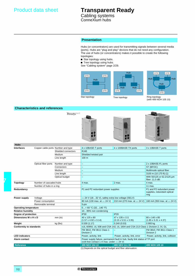
7/2
7
Product data sheet Transparent Ready 0
Cabling systemsConneXium hubs
Hubs (or concentrators) are used for transmitting signals between several media(ports). Hubs are “plug and play” devices that do not need any configuration.The use of hubs (or concentrators) makes it possible to create the followingtopologies:b Star topology using hubs.b Tree topology using hubs.See “Cabling system” page 2/29.
(1) Depends on the optical budget and fiber attenuation.
Presentation
DTE DTE
DTE DTE DTE DTEDTE
DTEDTE
Star topology Ring topology(with 499 NOH 105 10)
Tree topology
Hub
Hub
HubHub
Hub
Hub Hub
Characteristics and references
HubsInterfaces Copper cable ports Number and type 4 x 10BASE-T ports 4 x 100BASE-TX ports 3 x 10BASE-T ports
Shielded connectors RJ45
Medium Shielded twisted pairLine length 100 m
Optical fiber ports Number and type – 2 x 10BASE-FL portsConnectors – ST (BFOC)
Medium – Multimode optical fiberLine length – 3100 m (10 170 ft) (1)Optical budget – With 50/125 or 62.2/125 µm
fiber: 11.5 dB:Topology Number of cascaded hubs 4 max. 2 max. 4 max.
Number of hubs in a ring – 11 max.Redundancy P1 and P2 redundant power supplies P1 and P2 redundant power
supplies, redundant opticalring
Power supply Voltage c 24 V (18…32 V), safety extra low voltage (SELV)Power consumption 80 mA (130 max. at c 24 V) 210 mA (270 max. at c 24 V) 160 mA (350 max. at c 24 V)Removable terminal 5-pin
Operating temperature 0…+ 60 °C (32…140 °F)Relative humidity 10…95% non condensingDegree of protection IP30 IP20
Dimensions W x H x D mm (in) 40 x 125 x 80(1.57 x 4.92 x 3.14)
47 x 135 x 111(3.15 x 5.51 x 3.35)
80 x 140 x 85(1.85 x 5.31 x 4.37)
Weight kg (lbs) 0.530 (1.17) 0.240 (0.53) 0.900 kgConformity to standards cUL 60950, UL 508 and CSA 142, UL 1604 and CSA 213 Class 1 Division 2, e, GL
FM 3810, FM 3611 Class 1Division 2
– FM 3810, FM 3611 Class 1Division 2
LED indicators Power, activity, link Power, activity, link, error Power, activity, link, collision
Alarm contact Power supply failure, permanent fault in hub, faulty link status of TP port(volt-free contact 1 A max. under c 24 V)
Reference 499 NEH 104 10 499 NEH 111 00 499 NOH 105 10

7/3
7
Product data sheet Transparent Ready 0
Cabling systemsConneXium transceivers
The use of ConneXium transceivers makes it possible to perform the following:b Creation of linear fiber optic bus topologies, for products with twisted pair cableEthernet connection.b Interfacing products with twisted pair cable Ethernet connection with fiber opticcable.
Transceivers are “plug and play” devices that do not need any configuration. See“Cabling system” page 2/29.
ConneXium transceivers provide fiber optic connections for transmission in areassubject to interference (high levels of electromagnetic interference) and for longdistance communications.
(1) Depends on the optical budget and fiber attenuation.
Presentation
DTE
DTEDTE
Linear topology on optical fiber
Characteristics and references
TransceiversInterfaces Copper cable port Number and type 1 x 10BASE-T port 1 x 100BASE-TX port
Shielded connectors RJ45
Medium Shielded twisted pairLine length 100 m (328 ft)
Optical fiber ports Number and type 1 x 10BASE-FL port 1 x 100BASE-FX port
Connectors ST (BFOC) SCMedium Multimode optical fiberLine length 3100 m (10 170 ft) (1)
Signal attenuation 11.5 dB with 50/125 µm fiber11.5 dB with 62.5/125 µm fiber
8 dB with 50/125 µm fiber11 dB with 62.5/125 µm fiber
Redundancy P1 and P2 redundant power suppliesPower supply Voltage c 24 V (18…32), safety extra low voltage (SELV)
Power consumption 80 mA (100 max. at c 24 V) 160 mA (190 max. at c 24 V)
Removable terminal 5-pinOperating temperature 0…+ 60 °C (32…140 °F)Relative humidity 10…95% non condensing
Degree of protection IP30 IP20Dimensions W x H x D mm (in) 40 x 134 x 80 (1.57 x 5.47 x 3.14) 47 x 135 x 111 (3.15 x 5.51 x 3.35)Weight kg (lbs) 0.520 (1.15) 0.230 (0.50)
Conformity to standards cUL 60950, UL 508 and CSA 142, UL 1604 and CSA 213 Class 1 Division 2, e, GLFM 3810, FM 3611 Class 1 Division 2 –
LED indicators P1 and P2 power supplies, Ethernet link/port status
Alarm contact Power supply failure, permanent fault in hub, faulty link status of TP port(volt-free contact 1 A max. under c 24 V)
Reference 499 NTR 100 10 499 NTR 101 00

7/4
7
Product data sheet Transparent Ready 0
Cabling systemsConneXium switches
Presentation
Switches (see “Cabling system” page 2/32) are used toincrease the limits of architectures based on hubs ortransceivers, by separating collision domains. Higherlayer communication is provided between the ports,and collisions at link layer are not propagated (filtering).They therefore improve performance by betterallocation of the pass band due to the reduction ofcollisions and the network load.Certain Connexium switches also enable redundantarchitectures to be created on twister pair copper orfiber optic ring.Switches are “plug & play” devices that do not need anyconfiguration. They can also be administered remotelyvia the SNMP or HTTP protocols for monitoring anddiagnostics purposes.
DTE
DTEDTE
DTE DTE
DTE DTE
DTE DTE
DTE
DTEDTE
DTE DTE
DTE
DTEDTE
DTE DTE
DTE DTE
100 Mbit/soptical ring
Collision domain 1 Collision domain 2
Collisiondomain 3
Characteristics and references
Switches Unmanagedbasic
Shielded twisted pair and optical fiber, unmanaged
Interfaces Copper cable ports Number and type 5 x 10BASE-T/100BASE-TX ports
4 x 10BASE-T/100BASE-TX ports
3 x 10BASE-T/100BASE-TX ports
4 x 10BASE-T/100BASE-TX ports
3 x 10BASE-T/100BASE-TX ports
Shielded connectors RJ45
Medium Shielded twisted pairMax. distances 100 m (328 ft)
Optical fiber ports Number and type – 1 x 100BASE-FXport
2 x 100BASE-FXports
1 x 100BASE-FXport
2 x 100BASE-FXports
Connectors – SC
Medium – Multimode fiber Monomode fiberFiber length – 3100 m (10 170 ft) (1) 15 000 m (49 210 ft) (1)Optical budget – 8 dB with 50/125 µm fiber 16 dB with 10/125 µm fiber
Topology Number of switches Cascaded –Redundant in a ring –
Power supply redundancy – P1 and P2 redundant power suppliesPower supply Voltage c 24 V
(19.2…30 V)c 24 V (18…32 V), safety extra low voltage (SELV)
Power consumption 100 mA (120 max.) 5.4 W 5.9 W 5.4 W 5.9 WRemovable terminals 3-pin 5-pin
Operating temperature 0…+ 60°C (32…140 °F)Relative humidity 10…95% non
condensingMax. 95% non condensing
Degree of protection IP20Dimensions W x H x D mm (in) 75.2 x 143 x 43
(2.96 x 5.63 x1.69)
47 x 135 x 111(3.15 x 5.51 x 3.35)
Weight kg (lbs) 0.190 (0.42) 0.330 (0.72) 0.335 (0.74) 0.330 (0.72) 0.335 (0.74)Conformity to standards UL508,CSA 1010,
EN 61131-2cUL 60950, UL 508 and CSA 142, UL 1604 and CSA 213 Class 1 Division2, e, GL
LED indicators Power supply,ETH link status,10/100 Mbps
P1 and P2 power supplies, Ethernet link status, transmission activity
Alarm contact Power supply failure, permanent fault in hub, faulty link status of TP port (volt-free contact 1 Amax. under c 24 V)
Reference 499 NES 251 00 499 NMS 251 01r
499 NMS 251 02r
499 NSS 251 01r
499 NSS 251 02r
r Available later(1) Depends on the optical budget and fiber attenuation.

7/5
7
Product data sheet(continued)
Transparent Ready 0
Cabling systemsConneXium switches
Characteristics and references (continued)
Switches Unmanaged, copper Managed, copper Managed, copper + fiberInterfaces Copper cable ports Number and type 8 x 10BASE-T/
100BASE-TX ports5 x 10BASE-T/100BASE-TX ports2 x 100BASE-TX ports
5 x 10BASE-T/100BASE-TX ports
Shielded connectors RJ45Medium Shielded twisted pair
Max. distances 100 m (328 ft)Optical fiber ports Number and type – 2 x 100BASE-FX ports
Connectors – SC
Medium – Multi mode optical fiberFiber length – 3100 m (10 170 ft) (1)Optical budget – 8 dB with 50/125 µm fiber (2)
11 dB with 62.5/125 µm fiberEthernet services – FDR client, multicast filtering for optimization of the Global Data
protocol (3)Topology Number of switches Cascaded – 2 max.
Redundant in a ring – 50 max.Redundancy P1 and P2 redundant power suppliesPower supply Voltage c 18…32 V, safety extra low voltage (SELV)
Power consumption 125 mA (290 max.) 7.5 W 9 WRemovable terminals 5-pin
Operating temperature 0…+ 60°C 0…+ 55°C
Relative humidity 10…95% non condensingDegree of protection IP20Dimensions W x H x D mm (in) 47 x 135 x 111
(3.15 x 5.51 x 3.35)110 x 131 x 111 mm(4.33 x 5.16 x 4.37)
Weight kg (lbs) 0.230 (0.72) 0.460 (1.00)
Conformity to standards cUL 60950, UL 508 and CSA 14, UL 1604 and CSA 213 Class 1 Division 2, e, GLLED indicators P1 and P2 power
supplies, Ethernet linkstatus,
P1 and P2 power supplies, Ethernet link status, redundancymanagement
Alarm contact Power supply failure, permanent fault in hub, faulty link status of TP port(volt-free contact 1 A max. under c 24 V)
Reference 499 NES 181 00 499 NES 171 00 499 NOS 171 00(1) Depends on the optical fiber budgt and fiber attenuation.(2) Or 11 dB with 32.5/125 µm fiber.(3) With for 499 NES 271 00 : VLAN, Portpriority, IGMP Snooping, SNTP, SNMP V2e and V3,
RSTP (Rapid Spanning Tree Protocol).

7/6
7
Product data sheet Transparent Ready 0
Cabling systemsConneXium gateways
ConneXium communication gateways are used for interconnecting the following:b Modbus/Ethernet TCP/IPb Modbus Plus/Ethernet TCP/IPby providing multiple ports to adapt to the different architectures.
Presentation
Characteristics and references
GatewaysFunctions Communication gateway Ethernet/Modbus serial link Ethernet/Modbus Plus
Interface for programming Ethernet/Modbus Ethernet Ethernet/Modbus Plus
Standard Ethernet TCP/IP communicationservices
Modbus TCP messagingSNMP Agent
Modbus TCP messaging Modbus TCP messagingSNMP Agent
Modbus SL (RS 232/RS 485 serial link) RTU/ASCII frameData rate 0.3 K…115.2 Kbps
–
Modbus Plus (RS 485 network) – Token bus, HDLC synchronous modeData rate 1 Mbps
Configuration Local or remote by Telnet inhyper terminal mode
Local using DOS Local or remote (1)
Interfaces Ethernet TCP/IP port Type 1 x 10BASE-T/100BASE-TX 1 x 10BASE-T1 x 10BASE21 x 10BASE5
1 x 10BASE-T/100BASE-TX
Shielded connectors RJ45 RJ45, BNC and AUI RJ45
Medium Shielded twisted pairMax. distances 100 m (327 ft)
Serial port Type 1 x Modbus SL 1 x Modbus Plus
Shielded connectors RJ45 9-way SUB-D connectorMedium Shielded twisted pair Shielded twisted pair (single or double)
Power supply Voltage c 9…30 V,a 9 …24 V
a 110/220 V (a 93.5 V…242 V), 47…63 Hz
Power consumption 3 W 1 A
Operating temperature 0…+ 60°C 0…+ 50°CRelative humidity 20…90% non condensing 10…95% non condensingDegree of protection IP20
Dimensions W x H x D mm (in) 35 x 95 x 60(1.38 x 3.74 x 2.36)
122 x 229 x 248(4.80 x 9.0 x 9.80)
Weight kg (lbs) 0.500 (1.10) 4.260 (9.40)Conformity to standards UL, CSA, FM 3611 Class 1
Division 2UL 508, CSA 142, e
LED indicators Activity, status, diagnostics PowerReference 174 CEV 300 20 174 CEV 200 30 174 CEV 200 40 r
r Available later(1) Local with additional keyboard and monitor, via a dedicated screen for basic diagnostic and
configuration. Remote, via intuitive Web pages for full configuration and diagnostic.

7/7
7
Product data sheet Transparent Ready 0
Cabling systemConneXium connection cables
ConneXium shielded connection cables are available in two versions to meet currentstandards and approvals:
b Standard EIA/TIA 568 shielded twisted pair cables:These cables conform to the EIA/TIA-568 standard, category 5, IEC 11801/EN50173 class D. Their fire behavior conforms to NFC 32070# class C2 and IEC 322/1,Low Smoke Zero Halogen (LSZH).
b UL and CSA 22.1 approved shielded twisted pair cables:These cables are UL and CSA 22.1 approved. Their fire resistance conforms toNFPA 70.
Presentation
490 NTp 000 pp
ReferencesStandard EIA/TIA 568 shielded twisted pair cablesDescription Pre-equipped at both ends Length
m (ft)Reference Weight
kgStraight-throughshielded twisted paircables
2 RJ45 connectorsFor connection to terminaldevices (DTE)
2 (6.56) 490 NTW 000 02 –
5 (16.4) 490 NTW 000 05 –12 (39.4) 490 NTW 000 12 –40 (131.2) 490 NTW 000 40 –
80 (262.5) 490 NTW 000 80 –
Description Pre-equipped at both ends Length Reference Weightkg
Crossed cordshielded twisted paircables
2 RJ45 connectorsFor connections betweenhubs, switches andtransceivers
5 (16.4) 490 NTC 000 05 –15 (49.2) 490 NTC 000 05 –
40 (131.2) 490 NTC 000 40 –80 (262.5) 490 NTC 000 80 –
UL and CSA 22.1 approved shielded twisted pair cablesDescription Pre-equipped at both ends Length Reference Weight
kgStraight-throughshielded twisted paircables
2 RJ45 connectorsFor connection to terminaldevices (DTE)
2 (6.56) 490 NTW 000 02U –5 (16.4) 490 NTW 000 05U –12 (39.4) 490 NTW 000 12U –
40 (131.2) 490 NTW 000 40U –80 (262.5) 490 NTW 000 80U –
Description Pre-equipped at both ends Length Reference Weightkg
Crossed cordshielded twisted paircables
2 RJ45 connectorsFor connections betweenhubs, switches andtransceivers
5 (16.4) 490 NTC 000 05U –15 (49.2) 490 NTC 000 05U –
40 (131.2) 490 NTC 000 40U –80 (262.5) 490 NTC 000 80U –
Fiber optic cablesDescription Pre-equipped at both ends Length
m (ft)Reference Weight
kgGlass fiber opticcables for terminaldevices (DTE) tohubs, switches andtransceivers
1 SC connector and1 MT-RJ connector
5 (16.4) 490 NOC 000 05 –
1 ST (BFOC) connector and1 MT-RJ connector
5 (16.4) 490 NOT 000 05 –
2 MT-RJ connectors 5 (16.4) 490 NOR 000 05 –
490 NOC 000 05
490 NOR 000 05
490 NOT 000 05

8

8/1
8
Contents 8 - Modbus-IDA organisationand Collaborative AutomationPartner Program 0
8 - Presentations and partner data sheets
b Modbus-IDA organisation . . . . . . . . . . . . . . . . . . . . . . . . . . . . . . . . . . . . page 8/2
b Program presentation
v Collaborative Automation Partner Program . . . . . . . . . . . . . . . . . . . . page 8/3
b Examples of partner offer
v ProSoft Technology . . . . . . . . . . . . . . . . . . . . . . . . . . . . . . . . . . . . . . . page 8/4
v ConnectBlue . . . . . . . . . . . . . . . . . . . . . . . . . . . . . . . . . . . . . . . . . . . . page 8/6
v ACKSYS . . . . . . . . . . . . . . . . . . . . . . . . . . . . . . . . . . . . . . . . . . . . . . . page 8/7
v DATA-LINC GROUP . . . . . . . . . . . . . . . . . . . . . . . . . . . . . . . . . . . . . . page 8/8
v Senside . . . . . . . . . . . . . . . . . . . . . . . . . . . . . . . . . . . . . . . . . . . . . . . . page 8/9

8/2
8
Presentation Transparent Ready 0
Modbus-IDA organisation
Modbus-IDA is a group of independent users and suppliers of automation devicesthat seeks to drive the adoption of the Modbus communication protocol suite and theevolution to address architectures for distributed automation systems across multiplemarket segments. Modbus-IDA will also provide the infrastructure to obtain andshare information about the protocols, their application and certification to simplifyimplementation by users resulting in reduced costs (e.g. the specifications of theModbus suite of protocols are availableon line, free of charge).
Modbus products are the solutions to Modbus users worldwide. Modbus-IDA helpsusers find suppliers through a visibility program that includes:b Member listing on the Modbus-IDA.org web site.b Product highlights in the Modbus newsletter and on the web.Join the discussion as Modbus-IDA embraces new technologies, and help guide thefuture of Modbus-IDA as part of the technical working groups. You can join on-line atwww.Modbus-IDA.org
Your Membership in Modbus-IDA helps provide a myriad of open technology benefitsto you and your employees. An extract of the benefits includes:b Access to a rich library of shared users and implementers experiences.b Participation in a dynamic resourceful User Forum.b Access to a consultant referral directory that brings together users and experts.b Newsletters and technical training programs.
The true benefit of any open standard is the assurance it provides to users that theproducts they buy will interoperate seamlessly. Unfortunately, any specification, nomatter how carefully written, is subject to interpretation and occasionalmisunderstanding. That's where conformance testing becomes valuable.
The Modbus Conformance Testing Program provides independent verification that abroad array of qualifications has been met in compliance with Modbus specifications.It provides end users with the comfort that their design and configuration process willproceed smoothly and assures suppliers that their products were developed inaccordance with key Modbus criteria.
This program is administered by Modbus-IDA.org and is performed at anindependent service provider, the Modbus/TCP Conformance Test Laboratory at theUniversity of Michigan.
The first edition of the TCP/IP MODBUS CD TOOLKIT v1.0 is a great collection ofresources, selected to assist users and developers in implementing Ethernet TCP/IPModbus servers or clients. This toolkit targets essential messaging services.Additional toolkits will be made available in the future to facilitate the deployment ofother Transparent Ready services such as Global Data, etc.
This resources toolkit provides Specifications, Implementation Guides,diagnostics, test tools and examples source code. Also included the certificationtest suite as developed and used by the Modbus Certification Laboratory at theUniversity of Michigan.
Take advantages of the Modbus-IDA.org web site: www.modbus-ida.org
Modbus-IDA presentationModbus-IDA organisation mission statement
Modbus-IDA Provides Visibility to Modbus and Modbus related Products
Benefits for component suppliers, Integrators and Users
Modbus protocol Conformance Testing Program
TCP/IP Modbus toolkit available through Modbus-IDA.org
Become involved with the Modbus-IDA.org

8/3
8
Presentation (continued) Transparent Ready 0
Collaborative Automation Partner ProgramTransparent Ready Partners
The Collaborative Automation approach is a way of sharing data, interconnectingsoftware tools, accessing information in real time at any point within an architecture...all with the aim of maximizing productivity.The "Collaborative Automation Partner Program" is a program for sharing technology.Its aim is to follow a collaborative approach to promote partner products and solutionsthat complement the Telemecanique offer within the world of industrial controlsystems. The products promoted in this program use technologies developed eitherby our partner organizations, or by Telemecanique (Modbus Plus or Fip networks,Modicon Quantum or Modicon Premium PLCs, Unity interfaces to name but a fewexamples), or they use standard technologies (Ethernet Modbus TCP, OPC, etc).
There are currently more than 100 member organizations in the "CollaborativeAutomation Partner Program" offering more than 700 products in total. There are 3categories of partner:b Technology partnersb Unity partnersb Transparent Ready partnersThe Transparent Ready partner offers are principally in the areas of wirelesscommunication TCP/IP based, gateways, servers, modems, bridges and remotemanagement solutions.
This chapter details several examples of Transparent Ready partner offers to helpyou build a complete system:b ConnectBlue (Bluetooth wireless communication)b ProSoft Technology (frequency hopping or Wi-Fi type wireless communication)b ACKSYS (Wi-Fi IEEE 802.11b wireless communication)b Data-Linc Group (Ethernet wireless communication based on standard IEEE802.11b, Wi-Fi compatible)b Senside (remote management services).
Complete list of Transparent Ready Partners available on the Web site of theprogramm (see below).
Find out more about the "Collaborative Automation Partner Program" at:www.collaborativeautomation-schneider-electric.comFor any additional information, contact:Mail: Collaborative Automation Partner Program - One High Street North Andover,MA 01845 USAE-mail: info.capp6us.schneider-electric.comFax: +1 978 975 9321
More information on how to join the partner program can be found on theCollaborative Automation website (address above).
Presentation of the partner programOverview
The program partners
Examples of Transparent Ready partners
Contacts

8/4
8
Presentation (continued) Transparent Ready 0
Collaborative Automation Partner ProgramProSoft Technology
The opening up of the 2.4 GHz band (2.4 x 10⁹ Hz) makes it simple to set up wirelesssolutions in industry (no license or declaration for private use). The wide pass bandprovides high speeds. Standards such as WiFi IEEE 802.11b and Bluetooth areemerging.The press and television are playing an important part in promoting these newtechnologies for “general public” and office applications. Industrial solutions are alsoavailable, and currently offer secure transmission and availability of wirelessnetworks.
The “2.4 GHz band” ranges between 2,400 and 2,483.5 MHz (with some variationsaccording to the country). The waves emitted by this band are reflected by obstacles(metal, etc) and are significantly attenuated by water and vegetable matter. Radiowaves are propagated in straight lines and are polarized. An absorbent object“screens” points located behind it.
An antenna is characterized by:b The shape of the transmission/reception field (the “pattern” which defines thedirection(s) in which the transmitted/received power is the strongest).b Its gain (its capacity to amplify the transmitted/received power when the signalpasses between copper and air or air and copper).b Its azimuth (which specifies the focusing of the field in relation to the verticalplane).
The units of measurement used for the transmitted/received power are:b mW: Unit of measurement of power. The maximum transmission power(at 2.4 GHz) is regulated: North America, Pacific: 250 mW. Europe, Asia, LatinAmerica: generally 100 mW.b dB: Conventional unit for the ratio of two values of the same type. In this case,radio-frequency powers. By convention the 10 x log10 (Pvariable/Pref) relationship isused. As a matter of interest, adding/subtracting 3 dB corresponds tomultiplying/dividing the signal amplitude by 2.b dBm: Unit for the ratio between a power measured in mW and 1 mW.b dBi: Unit for the ratio between [power measured at antenna output in a givendirection] and [measurement that would be taken at the same point if the power weredispersed over the whole sphere of the isotropic antenna (theoretical)]. This ratio isused to qualify the gain of an antenna in its principal direction.
An isotropic antenna is in theory totally omindirectional. The greater the radius of thesphere centered on the antenna, the lower the power measured at one point on thissphere. In practice, the sphere is “squashed” for “omnidirectional” antennae used at2.4 GHz, and forms a very flat toroid in the plane perpendicular to the axis of theantenna.For long distances, “directive” antennae concentrate the power in one directionrather than diffusing it over 360°. Antennae are placed at high points so that they arefree from absorbent objects close to the ground.
The waves emitted by one source may be reflected on items in the environment(machine frame, girders in buildings, metal doors, vehicles, etc). The compositewave resulting from the mixture of reflected waves may return to the initial transmitterwith a higher amplitude and cause interference on this transmitter.In the band we are interested in here, the wavelengths (λ = c/f) are betweenapproximately 12.08 cm and 12.5 cm.With radio transmission, data is transported in the modulation (phase, frequency, etc)of the “carrier” wave. Using all the carrier waves in a frequency band (or spectrum)considerably increases the transmission speed. This is the “Spread Spectrum”:b DSSS technologies operate using “direct transmission” in the frequency band(“Direct Signal”). Each data packet occupies the whole spectrum.b FHSS technologies operate in “frequency hops” within the spectrum (“FrequencyHopping”). Data is transmitted in smaller packets, sent one after the other in narrowsub-bands within the overall band.
DSSS and FHSS were developed one after the other from military applications in theSecond World War. FHSS is a little slower, but offers greater reliability and securityfor data transfers.
Wireless industrial EthernetPopularity of wireless Ethernet
Main points of the theory

8/5
8
Presentation (continued) Transparent Ready 0
Collaborative Automation Partner ProgramProSoft Technology
The 802.11b standard uses DSSS technology. Each transmission band is spreadover 22 MHz. This means there are 3 channels (from a choice of 11 or 13) in the83.5 MHz band that do not overlap one another.This 22 MHz pass band offers high speeds (1 to 11 Mbps). But it is relatively sensitiveto interference (reflected waves, other networks, miscellaneous equipmenttransmitting in the free band). This means precautions should be taken, in particularin industrial environments.A single-frequency interfering signal can block the use of the entire 22 MHz band. Itseffect is similar to that of a collision signal on Ethernet (several subscribers talkingon the network simultaneously): the “line” is temporarily blocked. The site must be“audited” to anticipate this type of problem.The RLX-FH uses FHSS technology. Each of the transmission sub-bands is reducedto around 300 kHz. Up to 32 networks can simultaneously share the entire 83.5 MHzspectrum (they use each sub-band one after the other). The individual speed of eachof the 32 channels is 250 Kbps.Amongst other advantages, narrowband transmission makes it easier to “reject”interference outside the band being used. This significantly improves thesignal/noise level and limits reductions (even stopping) in transmission speed. Inaddition, a data packet that cannot be transmitted correctly in one sub-band isautomatically re-transmitted in the next channel sub-band. Observed from theoutside of the wireless network, the sequence of sub-bands seems to be random.
The RLX-FH radio modem is compatible with Modbus TCP messaging and programloading.b Operating temperature: - 40…+75°C.b Shock and vibration: IEC 60068-2-6 and IEC 60068-2-27.b Power supply: c 6…28 V.b Industrial unit: hardened, for mounting on DIN rail.b 32 channels (wireless networks) simultaneously on one site.b Each radio can be configured as Master/Keeper, Remote or Repeater station.b Repeaters can also take field devices.b Useful data rate of each channel: 250 Kbps.b Serial link or Ethernet TCP/IP version.b Network security (protection against intrusion) and communication reliability (nodata loss, no network power outage).b Double antenna and special signal processing algorithms (in order to avoidproblems connected with multiple reflections and attenuation).b Applications possible in hazardous areas (ATEX for Europe under development).b Low cost and 3 year warranty as standard.
The RLX-IH radio modem is compatible with Modbus TCP messaging, programloading and FactoryCast Web page viewing.b Operating temperature: - 30…+60°C, humidity: 90%.b Power supply: c 10…24 V.b Compact extruded aluminum unit, for mounting on DIN rail.b “Industrial Hotspot” function for mobile equipment.b “Inter-Hotspot” wireless links.b Transfers at 11, 5.5, 2 and 1 Mbps (11 or 13 channels depending on the region).b Redundant Master/Keeper radio and automatic network overlap function for betternetwork reliability.b Encoding, authentication and checking of MAC ID address for better networksecurity (TKIP, WEP, 802.11X, MAC White list).b Embedded configuration and diagnostic software (html pages).
Installing radio solutions requires specialist expertise. Please contact our partner:
ProSoft Technology, Inc.Tel: +1 (661) 716 5100Fax: +1 (661) 716 5101E-mail: [email protected]: www.prosoft-technology.com and www.radiolinx.comWorldwide distributors: http://www.radiolinx.com/distributors
Presentation (continued)
RadioLinx wireless industrial offerRadioLinx RLX-FH (frequency hopping) Ethernet
RadioLinx RLX-IH (Industrial HotspotTM) IEEE 802.11b
Contact

8/6
8
Presentation (continued) Transparent Ready 0
Collaborative Automation Partner ProgramConnectBlue
The Bluetooth Serial Port Adapter enables replacement of serial cables withBluetooth wireless technology. Bluetooth is robust, proven and well suited forindustrial applications and is license free to use.
The Serial Port Adapter connected to the RS232/RS422/RS485 port of the industrialdevice acts like a wireless connection point to the device. A PC, laptop, PDA or anyother serial device may connect wirelessly to the industrial device for ranges up to> 100m. It supports both point-to-point and point-to-multipoint configurations.TheSerial Port Adapter is configured using a PC Configuration Wizard or by use of ATcommands.
The Serial Port Adapter is available in wall/DIN-rail mounted IP22 or wall mountedIP 65.
1 Operators, programmers etc. are provided wireless access to an industrial devicefor configuration, programming, diagnostics using a standard computer, laptop orPDA.
2 The Serial Port Adapter supports Wireless Multidrop. It is used to replace anRS 422/RS 485 multidrop network (running e.g. Modbus protocol) with Bluetooth.
Installing radio solutions requires specialist expertise. Please contact our partner:
Martin Engdahl – Product ManagerConnectBlue AB, Isbergs gata 3, Malmö, SE-21119, SwedenTel: +46 (0)40 6307100Fax: +46 (0)40-237137E-mail: [email protected] Web: www.connectblue.se
Presentation connectBlue Wireless offerBluetooth Serial Port Adapter (RS232, RS422 or RS485)
IP 22 version IP 65 version
Use Cases - Serial Port Adapter (RS 232, RS 422 or RS 485)
Contact

8/7
8
Presentation (continued) Transparent Ready 0
Collaborative Automation Partner ProgramACKSYS
ACKSYS is a French company specializing in telecommunication solutions for allindustrial sectors where high performance, reliability and longevity are majorrequirements (industrial control systems, telecommunications, aviation, military,transport and healthcare).
ACKSYS also offers a range of wireless equipment based on the WiFi standard IEEE802.11b. This range comprises an Ethernet/WiFi access point, an Ethernet/WiFibridge and an RS 232, RS 422/RS 485 serial link server on Ethernet WiFi that alsooperates as a gateway between serial Modbus devices and the Modbus TCPnetwork.
These devices can be used to:
b Build a wireless Ethernet network infrastructure (WL-ACCESS devices andWL-BRIDGE devices.b Connect two separate Ethernet networks without using any additional wiring(WL-BRIDGE).b Connect serial link devices to the wireless Ethernet network.b Connect an RTU serial Modbus device to a wireless Modbus TCP Ethernetnetwork (WL-COMETH device in gateway mode).b Create a wireless connection between two serial link devices (WL-COMETHdevice in full duplex radio modem mode).
Unlike conventional, non-WiFi radio modems, which require same brand devices atboth ends of the connection, WL-COMETH offers total interoperability of all devicesconforming to standard IEEE 802.11b within the network, meaning that a singleaccess point can communicate with more than 100 WL-COMETH devices. It is alsopossible to replace a wired full duplex serial link using two WL-COMETH radiodevices.
IP65 weatherproof versions are also available for outdoor applications orapplications in damp or dusty environments.
WL-COMETH is available in versions with 1, 2 and 4 RS232, RS422/RS485 serialchannels. All WL range devices have a built-in 85/264VAC & 100/370VDC or lowvoltage 9/36VDC power supply.
They have universal mounting options (in enclosure, or wall or din rail mounting).Antennas are mounted on RSMA screw connectors allowing the use of high gainantennae for long distance applications.
Installing radio solutions requires specialist expertise. Please contact our partner:
Eric CARIOU3-5 rue du Stade PO BOX 4580POISSY CEDEX 78302 FranceTel: 33 1 39 11 62 81Fax: 33 1 39 11 47 96E-mail: [email protected]: www.acksys.fr
ACKSYS wireless solutionsACKSYS
WL-COMETH WL-COMETH, IP 65
Serial Modbus to Modbus TCP connection
Modbus TCP network interconnection
WL-BRIDGE WL-ACCESS
Modbus TCPnetwork
Modbus SL (RS485)
WiFi radio2.4 GHz
Modbus TCPnetwork
WiFi radio2.4 GHz
Modbus TCPnetwork
Wireless solutions for industry (WiFi IEEE 802.11b)
Contact

8/8
8
Presentation (continued) Transparent Ready 0
Collaborative Automation Partner ProgramDATA-LINC GROUP
Founded in 1988, Data-Linc Group is the leading provider of industrial datacommunication solutions. Data-Linc Group designs and manufactures highperformance, superior quality modems for a broad range of industrial applications.Their complete line of industrial grade modems and networking products consistentlyprovide reliable, robust data communications even in the harshest environments.
Wireless Ethernet Modems offer superior range (SRM6210E up to 40 kilometres &SRM6310E up to 16 kilometres without repeaters and multiples of this distance withrepeaters), features and benefits. The modems utilize advanced frequency hoppingspread spectrum technology to insure the ultimate in data reliability and integrity inchallenging industrial environments. The modems are factory pre-configured foreasy, hassle-free installation. see www.data-linc.com/products.htm
FastLinc Industrial Ethernet Wireless Modems are a high-speed, secure wirelesssolution using 2.4 GHz direct sequence technology. FastLinc modems have a ratedrange of 5 miles with unobstructed line-of-sight, farther using repeaters and/or highergain antennas. With an output power much higher than commercial IEEE 802.11bproducts, they provide longer outdoor range and broader indoor coverage.
Installing radio solutions requires specialist expertise. Please contact our partner:
Jim Steffey3535 Factoria Blvd. SE Bellevue, WA 98006 USATel: 425 882 2206Fax: 425 867 0865E-mail: [email protected] web site: www.data-linc.com
Direct access to the DATA-LINC offer in partnership with Schneider Electric,including applications examples: www.data-linc.com/saally.htm
Wireless solutions DATA-LINCDATA-LINC
SRM Long Range Radio Modems
SRM6210E & SRM6310E Wireless Ethernet Modems
FastLinc wireless Ethernet 802.11b modem (Wi-Fi compliant)
Contact
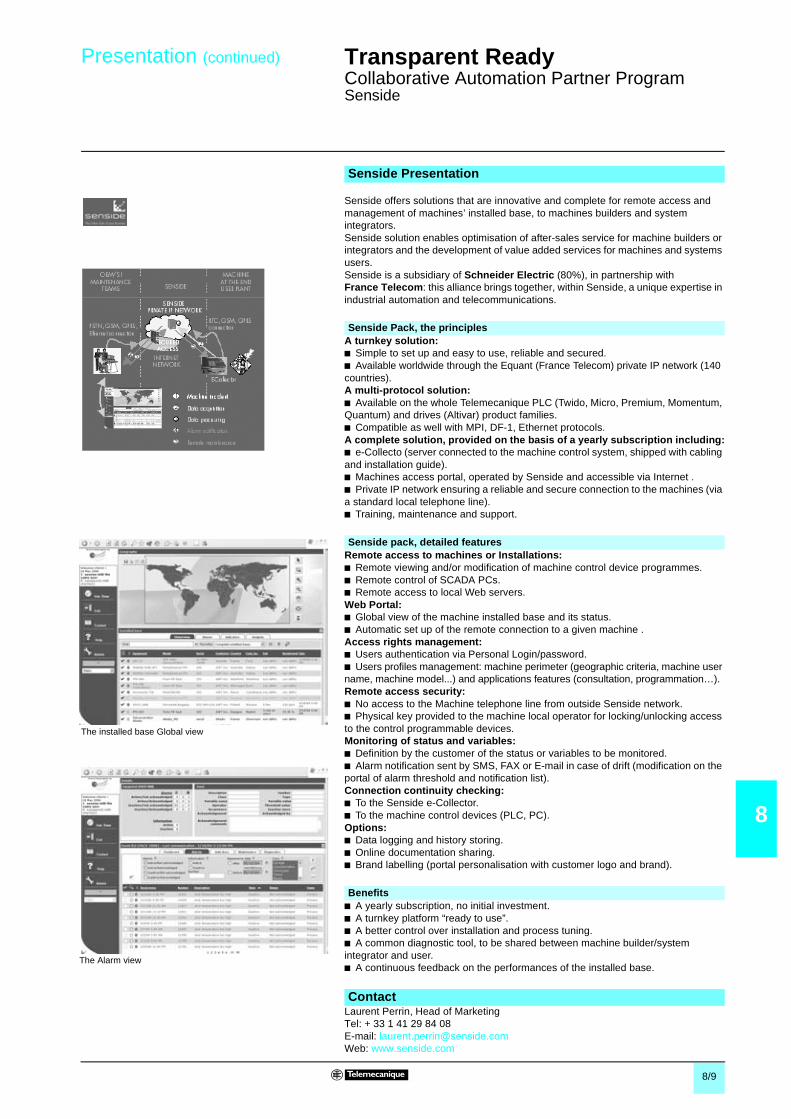
8/9
8
Presentation (continued) Transparent Ready 0
Collaborative Automation Partner ProgramSenside
Senside offers solutions that are innovative and complete for remote access andmanagement of machines’ installed base, to machines builders and systemintegrators.Senside solution enables optimisation of after-sales service for machine builders orintegrators and the development of value added services for machines and systemsusers.Senside is a subsidiary of Schneider Electric (80%), in partnership withFrance Telecom: this alliance brings together, within Senside, a unique expertise inindustrial automation and telecommunications.
A turnkey solution:b Simple to set up and easy to use, reliable and secured.b Available worldwide through the Equant (France Telecom) private IP network (140countries).A multi-protocol solution:b Available on the whole Telemecanique PLC (Twido, Micro, Premium, Momentum,Quantum) and drives (Altivar) product families.b Compatible as well with MPI, DF-1, Ethernet protocols.A complete solution, provided on the basis of a yearly subscription including:b e-Collecto (server connected to the machine control system, shipped with cablingand installation guide).b Machines access portal, operated by Senside and accessible via Internet .b Private IP network ensuring a reliable and secure connection to the machines (viaa standard local telephone line).b Training, maintenance and support.
Remote access to machines or Installations:b Remote viewing and/or modification of machine control device programmes.b Remote control of SCADA PCs.b Remote access to local Web servers.Web Portal:b Global view of the machine installed base and its status.b Automatic set up of the remote connection to a given machine .Access rights management:b Users authentication via Personal Login/password.b Users profiles management: machine perimeter (geographic criteria, machine username, machine model...) and applications features (consultation, programmation…).Remote access security:b No access to the Machine telephone line from outside Senside network.b Physical key provided to the machine local operator for locking/unlocking accessto the control programmable devices.Monitoring of status and variables:b Definition by the customer of the status or variables to be monitored.b Alarm notification sent by SMS, FAX or E-mail in case of drift (modification on theportal of alarm threshold and notification list).Connection continuity checking:b To the Senside e-Collector.b To the machine control devices (PLC, PC).Options:b Data logging and history storing.b Online documentation sharing.b Brand labelling (portal personalisation with customer logo and brand).
b A yearly subscription, no initial investment.b A turnkey platform “ready to use”.b A better control over installation and process tuning.b A common diagnostic tool, to be shared between machine builder/systemintegrator and user.b A continuous feedback on the performances of the installed base.
Laurent Perrin, Head of MarketingTel: + 33 1 41 29 84 08E-mail: [email protected]: www.senside.com
Senside Presentation
Senside Pack, the principles
The installed base Global view
The Alarm view
Senside pack, detailed features
Benefits
Contact

9

9/1
9
Contents 9 - Services 0
9 - Technical informationb Automation product certifications . . . . . . . . . . . . . . . . . . . . . . . . . . . . . . page 9/2
Schneider Electric worlwideb Addresses . . . . . . . . . . . . . . . . . . . . . . . . . . . . . . . . . . . . . . . . . . . . . . . . page 9/4
Indexb Product reference index . . . . . . . . . . . . . . . . . . . . . . . . . . . . . . . . . . . . page 9/10

9/2
9
Transparent Ready 0
Automation product certifications
In some countries, certification of certain electrical components is enforced by law.A standard conformity certificate is then issued by the official organization. Eachcertified product must carry approval symbols when enforced.Use on board merchant navy vessels generally requires prior approval(= certification) of an electrical device by certain marine classification authorities.
The table below shows the situation as of the 01.06.2004 for certifications obtainedor pending from organizations for base PLCs. An overview of certificates forTelemecanique products is available on our Internet web site :www.telemecanique.com
Key Certification body CountryCSA Canadian Standards Association Canada
C-Tick Australian Communication Authority Australia
GOST Institut de recherche Scientifique Gost Standardt C.I.S., Russia
UL Underwriters Laboratories USAKey Classification authority Country
ABS American Bureau of Shipping USA
BV Bureau Veritas France
DNV Det Norske Veritas Norway
GL Germanischer Lloyd Germany
LR Lloyd's Register United-KingdomRINA Registro Italiano Navale Italiy
RMRS Register of Shipping C.I.S.
Product certificationsCertifications
C-Tick
Certified HazardouslocationsClass I, div 2(1)
Pendingcertification UL CSA ACA SIMTARS GOST
USA Canada Australia Australia CEI, Russia US
Advantys STBAltivar ATV 38/58ConneXium (2)ECC21 for CM 3000/CM 4000EGX gatewaysInductel XGK SMagelis iPCMagelis XBT FMagelis XBT GMomentum FMPremium PL7 CSA
Unity CSAQuantum Concept FM
Unity FMTSX MicroTwido (3) CSA
(1) Hazardous locations : CSA 22.2 N° 213 ou FM 3611, certified products are suitable for usein Class I, division 2, groups A, B, C et D or non-hazardous locations only
(2) Depending on product, see pages 7/2 à 7/6.(3) cULus north-american certification (Canada and US).
Local certificationsBG Germany TSX DPZ 10D2A safety module (TSX Micro)
TSX PAY 262/282 safety modules (Premium)
AS-Interface Europe TSX SAZ 10 master module (TSX Micro)TSX SAY 100/1000 master modules (Premium)TBX SAP 10 Fipio bus/AS-Interface bus gateway

9/3
9
Transparent Ready 0
Automation product certificationsCommunity regulations
The opening of European markets implies a harmonization of regulations in thevarious European Union member states.European Directives are documents used to remove obstacles to the free movementof goods and their application is compulsory in all states of the European Union.Member states are obliged to transcribe each Directive into their national legislationand, at the same time, to withdraw any conflicting regulations.The Directives, particularly those of a technical nature with which we are concerned,only set objectives, called “general requirements”.The manufacturer must take all necessary measures to ensure that his productsconform to the requirements of each Directive relating to his equipment.As a general rule, the manufacturer affirms that his product conforms to thenecessary requirements of the Directive(s) by applying the e label to his product.e marking is applied to Telemecanique products where relevant.
b e marking on a product means that the manufacturer certifies that his productconforms to the relevant European Directives ; it is necessary in order that a productwhich is subject to a Directive(s) can be marketed and freely moved within theEuropean Union.b e marking is intended solely for the national authorities responsible for marketregulation.
For electrical equipment, only conformity of the product to standards indicates that itis suitable for use, and only a guarantee by a recognised manufacturer can ensurea high level of quality.One or more Directives, as appropriate, may apply to our products, in particular :b The Low Voltage Directive 72/23/EEC amended by Directive 93/68/EEC : emarking under the terms of this Directive is compulsory as of 1 January 1997.b The Electromagnetic Compatibility Directive 89/336/EEC, amended by Directives92/31/EEC and 93/68/EEC : e marking on the products covered by this Directivehas been compulsory since 1 January 1996.
Marine classificationMarine classification des authorities
CertifiedPendingcertification ABS BV DNV GL LR RINA RMRS
USA France Norway Germany Unit.-Kingdom Italiy C.I.S.
Advantys STBAltivar ATV 38/58ConneXium (1)ECC21 for CM 3000/CM 4000EGX gatewaysInductel XGK SMagelis iPCMagelis XBT FMagelis XBT GMomentumPremium PL7
Unity (2)
Quantum ConceptUnity (2)
TSX MicroTwido
(1) Depending on products, see pages 7/2 à 7/6.(2) Request for Marine certifications forecast 4th quarter 2004.
Community regulationsEuropean directives
The significance of e marking

0/4
9
Schneider Electric worldwide 0
Afghanistan Contacts are assured by Schneider Electric India
Albania Contacts are assured by Schneider Electric Austria
Algeria b Schneider Electric voie A Lot C22Zone industrielle Rouiba - Alger
Tel. : +213 21 92 97 02 à 09Fax : +213 21 92 97 00 à 01
Andorra Contacts are assured by Schneider Electric France
Angola Contacts are assured by Schneider Electric South Africa
Anguilla Contacts are assured by Schneider Electric Dominican Rep.
Antartica Contacts are assured by Schneider Electric Brazil
Antigua & Barbuda Contacts are assured by Schneider Electric Dominican Rep.
Argentina b Schneider Argentina Viamonte 2850 - 1678 Caseros(provincia Buenos Aires)
Tel.: +54 1 716 88 88Fax: +54 1 716 88 33
www.schneider-electric.com.ar
Armenia Contacts are assured by Schneider Electric Russian Fed.
Aruba Contacts are assured by Schneider Electric Dominican Rep.
Australia b Schneider Electric (Australia) Pty.Limited
2 Solent CircuitNorwest Business ParkBaulkham Hill _ NSW 2153
Tel.: +61 298 51 28 00Fax: +61 296 29 83 40
www.schneider.com.au
Austria b Schneider Austria Ges.m.b.H. Birostrasse 111239 Wien
Tel.: +431 610 540Fax: +431 610 54 54
www.schneider-electric.at
Azerbaijan Contacts are assured by Schneider Electric Russian Fed.
Bahamas b Schneider Electric Union VillagePO Box 3901 - Nassau
Tel. : +1 242 327 42 91Fax : +1 242 327 42 91
www.squared.com
Bahrain b Schneider Electric Floor 1 - Juma BuildingAbu Horaira AvenuePO Box 355 - 304 Manama
Tel.: +97 322 7897Fax: +97 321 8313
Bangladesh Contacts are assured by Schneider Electric India
Barbados Contacts are assured by Schneider Electric Dominican Rep.
Belarus b Schneider Electric Industries SA Prospect Macherova 5, of. 202220004 Minsk
Tel. : +375 172 23 75 50Fax : +375 172 23 97 61
Belgium b Schneider Electric nv/sa Dieweg 3B - 1180 Brussels
Tel.: +3223737711Fax: +3223753858
www.schneider-electric.be
Belize Contacts are assured by Schneider Electric USA
Benin Contacts are assured by Schneider Electric Ivory Coast
Bermuda Contacts are assured by Schneider Electric Dominican Rep.
Bhutan Contacts are assured by Schneider Electric India
Bolivia Contacts are assured by Schneider Electric Chile
Bosnia and Herzegovina Contacts are assured by Schneider Electric Croatia
Botswana Contacts are assured by Schneider Electric South Africa
Bouvet island Contacts are assured by Schneider Electric Dominican Rep.
Brazil b Schneider Electric Brazil Ltda. Avenida Das Nações Unidas 23223Jurubatuba - CEP 04795-907São Paulo-SP
Tel.: +55 55 24 52 33Fax: +55 55 22 51 34
www.schneider-electric.com.br
Brunei (Darussalam) Contacts are assured by Schneider Electric Singapore
Bulgaria b Schneider Electric Expo 2000, Boulevard Vaptzarov1407 Sofiav
Tel.: +3592 919 42Fax: +3592 962 44 39
www.schneiderelectric.bg
Burkina Faso Contacts are assured by Schneider Electric Ivory Coast
Burundi Contacts are assured by Schneider Electric Kenya
Cambodia Contacts are assured by Schneider Electric Viet Nam
Cameroon b Schneider Electric Cameroon 166, rue de l'Hôtel de VilleBP12087 - Douala
Tel.: +237 343 38 84Fax: +237 343 11 94
Canada b Schneider Canada 19, Waterman AvenueM4 B1Y2 Toronto - Ontario
Tel.: +1 416 752 8020Fax: +1 416 752 4203
www.schneider-electric.ca
Cape Verde Contacts are assured by Schneider Electric Senegal
Caribee Contacts are assured by Schneider Electric Dominican Rep.
Cayman islands Contacts are assured by Schneider Electric Dominican Rep.
Central African Republic Contacts are assured by Schneider Electric Cameroon
Chad Contacts are assured by Schneider Electric Cameroon
Chile b Schneider Electric Chile S.A. Avda. Pdte Ed. Frei Montalva, 6001-31Conchali - Santiago
Tel.: +56 2 444 3000Fax: +56 2 423 9335
www.schneider-electric.co.cl
China b Schneider Beijing Landmark bldg-Room 18018 North Dong Sanhuan RdChaoyang District100004 Beijing
Tel.: +86 10 65 90 69 07Fax: +86 10 65 90 00 13
www.schneider-electric.com.cn
Up-dated: 30-07-2003

Schneider Electric worldwide 0
Up-dated: 30-07-2003
9/5
9
Christmas island Contacts are assured by Schneider Electric Australia
Cocos (Keeling) islands Contacts are assured by Schneider Electric Australia
Colombia b Schneider Electric de ColombiaS.A.
Calle 45A #102-48Bogota DC
Tel.: +57 1 426 97 00Fax: +57 1 426 97 40
Comoros Contacts are assured by Schneider Electric la Reunion
Congo Contacts are assured by Schneider Electric Cameroon
Cook islands Contacts are assured by Schneider Electric Australia
Costa Rica b Schneider Centroamérica Ltda. 1.5 kmts oeste de la EmbajadaAmericana,Pavas, San José, Costa Rica C.A.Apartado: 4123-1000 San Jose
Tel.: +506 232-60-55Fax: +506 232-04-26
www.schneider-ca.com
Croatia b Schneider Electric SA Fallerovo Setaliste 22HR - 10000 Zagreb
Tel.: +385 1 367 100Fax: +385 1 367 111
Cuba b Schneider Electric Bureau de Liaison de La HavaneCalle 36- N°306-Apto1Entre 3ra y 5ta Avenida MiramarPlaya Habana
Tel.: +53 724 15 59Fax: +53 724 12 17
Cyprus b Schneider Electric Cyprus 28 General Timayia AvenueKyriakos Building, Block #A301Larnaca 6046
Tel.: +00357 248 12646Fax: +00357 246 37382
Czech Republic b Schneider Electric CZ, s.r.o. Thámova 13Praha 8 - 186 00
Tel.: +420 2 810 88 111Fax: +420 2 24 81 08 49
www.schneider-electric.cz
Democratic Rep. of Congo Contacts are assured by Schneider Electric Cameroon
Denmark b Schneider Electric A/S Baltorpbakken 14DK-2750 Ballerup
Tel.: +45 44 73 78 88Fax: +45 44 68 5255
www.schneider-electric.dk
Djibouti Contacts are assured by Schneider Electric Egypt
Dominican Republic b Schneider Electric Calle Jacinto ManonEsq. Federico GeraldinoEdificio D' Roca Plaza Suite 402,Ens. Paraiso - Santo Domingo
Tel.: +1 809 334 66 63Fax: +1 809 334 66 68
Ecuador b Schneider Electric Ecuador SA Av.Republica del Salvador 1082 y NacEdificio Mansion Blanca-Quito
Tel. : +593 2 224 42 42Fax : +593 2 224 42 94
Egypt b Schneider Electric Egypt sae 68, El Tayaran StreetNasr City, 11371 - Cairo
Tel.: +20 24 01 01 19Fax: +20 24 01 66 87
www.schneider.com.eg
El Salvador Contacts are assured by Schneider Electric USA
Equatorial Guinea Contacts are assured by Schneider Electric Cameroon
Eritrea Contacts are assured by Schneider Electric Egypt
Estonia b Lexel Electric Ehitajate tee 110EE 12618 Talinn
Tel. : +372 650 97 00Fax : +372 650 97 22
Ethiopia Contacts are assured by Schneider Electric Egypt
Falkland islands Contacts are assured by Schneider Electric Brazil
Faroe islands Contacts are assured by Schneider Electric Australia
Fiji Contacts are assured by Schneider Electric Australia
Finland b Schneider Electric Oy Sinimäentie 1402630 Espoo
Tel. : +358 9 527 000Fax : +358 9 5270 0376
www.schneider-electric.fi
France b Schneider Electric SA 5, rue Nadar92500 Rueil Malmaison
Tel.: +33 (0)1 41 29 82 00Fax: +33 (0)1 47 51 80 20
www.schneider-electric.fr
French Polynesia Contacts are assured by Schneider Electric Australia
French West Indies Contacts are assured by Schneider Electric Dominican Rep.
Gabon Contacts are assured by Schneider Electric Cameroon
Gambia Contacts are assured by Schneider Electric Senegal
Georgia Contacts are assured by Schneider Electric Russian Fed.
Germany b Schneider Electric GmbH Gothaer Straße 29D-40880 Ratingen
Tel.: +49210 240 40Fax: +492 10 240 49 256
www.schneiderelectric.de
Ghana b Schneider Electric Ghana PMB Kia3rd Floor Opeibea HouseAirport Commercial CenterLiberation road - Accra
Tel. : +233 21 70 11 687Fax : +233 21 77 96 22
Gilbraltar Contacts are assured by Schneider Electric Spain
Greece b Schneider Electric AE 14th km - RN Athens-LamiaGR - 14564 Kifissia
Tel.: +302 106 29 52 00Fax: +302 106 29 52 10
www.schneider-electric.com.gr
Greenland Contacts are assured by Schneider Electric United States
Grenada Contacts are assured by Schneider Electric Dominican Rep.
Guadeloupe Contacts are assured by Schneider Electric Martinique
Guam Contacts are assured by Schneider Electric Australia

Schneider Electric worldwide 0
Up-dated: 30-07-2003
9/6
9
Guatemala Contacts are assured by Schneider Electric United States
Guinea-Bissau Contacts are assured by Schneider Electric Sénégal
Guinea Contacts are assured by Schneider Electric Ivory Coast
Guyana Contacts are assured by Schneider Electric United States
Haiti Contacts are assured by Schneider Electric Dominican Rep.
Heard & Mac Donald isl. Contacts are assured by Schneider Electric Australia
Honduras Contacts are assured by Schneider Electric United States
Hong Kong b Schneider Electric (Hong Kong)Ltd
Room 3108-28, 31th Floor,Sun Hung Kai Centre,30 Harbour Road, Wanchai
Tel.: +852 25 65 06 21Fax: +852 28 11 10 29
Hungary b Schneider Electric HungáriaVillamossági Rt.
Fehérvári út 108 – 112H-1116 Budapest
Tel.: +36 1 382 26-06Fax: +36 1 206 1429
www.schneider-electric.hu
Iceland Contacts are assured by Schneider Electric Denmark
India b Schneider Electric India Max House, 1 Dr Jha Marg, Okhla110 020 New Dehli
Tel. : +91 11 631 85 84Tel. : +91 11 631 71 61
www.schneiderelectric-in.com
Indonesia b P.T. Schneider Indonesia Ventura Building 7th FloorJalan R.A. Kartini Kav.26Cilandak - 12430 Jakarta
Tel.: +62 +21 750 44 06Fax: +62 +21 750 44 15/ 16
www.schneider-electric.co.id
Iran (Islamic Republic of) b Telemecanique Iran 1047 Avenue VALI ASSRP.O. Box 15875-354715116 Teheran
Tel.: +98 218 71 01 42Fax: +98 218 71 81 87
Irak b Schneider Electric Industries SA 38050 Grenoble Cedex 9 Tel.: +33 04 76 60 54 27Fax: +33 04 76 60 56 60
Ireland b Schneider Electric Ireland Maynooth RoadCellbridge - Co. Kildare
Tel.: +353+0 1 6012200Fax: +353+0 1 6012201
www.schneiderelectric.ie
Italy b Schneider Electric S.p.A. Centro Direzionale ColleoniPalazzo Sirio - Viale Colleoni, 720041 Agrate Brianza (Mi)
Tel.: +39 39 655 8111Fax: +39 39 605 6237
www.schneiderelectric.it
Ivory Coast b Schneider Electric Afrique del'Ouest
Rue Pierre et Marie Curie18 BP 2027 Abidjan 18
Tel.: +225 21 75 00 10Fax: +225 21 75 00 30
Jamaica b Schneider Electric Shop#5, Plaza Dunrobin30 Dunrobin Avenue - Kingstown
Tel. : +1876 755 41 27Tel. : +931 87 74
Japan b Schneider Electric Japan Ltd Torigoe F. Bldg1-8-2, TorigoeTaito-Ku - 111-0054 Tokyo
Tel.: +81 358 35 35 81Fax: +81 358 35 35 85
www.schneider-electric.co.jp
Jordan b Schneider Electric Industr. Jordan Jordan University StreetAbu Al Haj Commercial Complex2nd Floor - Office # 202 - Amman
Tel.: 962 65 16 78 87Fax: 962 65 16 79 1
Kazakstan b Schneider Electric KazakhstanLiaison Office
Prospekt Abaia 157 off 9480009 Almaty
Tel. : +7 327 250 93 88Tel. : +7 327 250 63 70
Kenya b Schneider East Africa Power Technics ComplexMonbasa Road - PO Box 46345Nairobi
Tel. : +254 2.824.156Fax : +254 2.824.157
Kiribati Contacts are assured by Schneider Electric Australia
Korea b Schneider Electric Korea Ltd 3Floor, Cheil Bldg., 94-46, 7-KaYoungdeungpodong,Youngdeungpo-ku150-037 Seoul
Tel. : +82 2 2630 9700Fax : +82 2 2630 9800
www.csinfo.co.kr/schneider/
Kuwait b Schneider Electric Kuwait Al Gaas Tower - Sharq 2nd FloorPO Box 20092 - 13 061 Safat
Tel.: +965 240 75 46Fax: +965 240 75 06
Kyrgyz Republic Contacts are assured by Schneider Electric Russian Fed.
Laos Contacts are assured by Schneider Electric Thailand
Latvia b Lexel Electric 60A A.Deglava str.LV1035 Riga
Tel. : +371 780 23 74/75Fax : +371 754 62 80
Lebanon b Schneider Electric Liban Tabaris, Avenue Charles MalekImmeuble Ashada, 8P.O. Box 166223 - Beyrouth
Tel. : +961 1 20 46 20Tel. : +961 1 20 31 19
Lesotho Contacts are assured by Schneider Electric South Africa
Liberia Contacts are assured by Schneider Electric Ghana
Libya Contacts are assured by Schneider Electric Tunisia
Liechtenstein Contacts are assured by Schneider Electric Switzerland
Lithuania b Lexel Electric 44, Verkiu str.LT-2012 Vilnius
Tel. : +370 278 59 59/61Fax : +370 278 59 60
Loro Sae Contacts are assured by Schneider Electric Australia
Luxembourg b Schneider Electric Industrie SAS Agence de Metz1, Rue Graham Bell - BP n° 3519057075 Metz cedex 3 - France
Tel.: 33 03 87 39 06 03Fax: 33 03 87 74 25 96
www.schneider-electric.fr
Macau Contacts are assured by Schneider Electric China

Schneider Electric worldwide 0
Up-dated: 30-07-2003
9/7
9
Macedonia Contacts are assured by Schneider Electric Bulgaria
Madagascar Contacts are assured by Schneider Electric la Reunion
Malawi Contacts are assured by Schneider Electric South Africa
Malaysia b Schneider Electric (Malaysia) SdnBhd
No.11 Jalan U1/19, Seksyen U1Hicom-Glenmarie Industrial Park40150 Shah AlamSelangor Darul Ehsan
Tel. : (603) 7883 6333Fax : (603) 7883 6188
www.schneider-electric.com.my
Maldives Contacts are assured by Schneider Electric Reunion
Mali Contacts are assured by Schneider Electric Senegal
Malta Contacts are assured by Schneider Electric Tunisia
Marshall islands Contacts are assured by Schneider Electric Australia
Martinique b Schneider Electric Schneider ElectricImmeuble Cottrell - ZI de la Lézarde97232 Le Lamentin
Tel.: +05 96 51 06 00Fax: +05 96 51 11 26
Mauritania Contacts are assured by Schneider Electric Senegal
Mauritius b Schneider Electric Route côtièreCalodyne - Mauritius
Tel.: 230 282 18 83Fax: 230 282 18 84
Mayotte Contacts are assured by Schneider Electric Reunion
Mexico b Groupe Schneider Mexico Calz. Rojo Gomez N° 1121-ACol. Guadalupe del MoralMéxico, D.F. - C.P. 09300
Tel.: +525 686 30 00Fax: +525 686 24 09
www.schneider-electric.com.mx
Micronesia Contacts are assured by Schneider Electric Australia
Moldova Contacts are assured by Schneider Electric Romania
Monaco Contacts are assured by Schneider Electric France
Mongolia Contacts are assured by Schneider Electric Russian Fed.
Montserrat Contacts are assured by Schneider Electric Dominican Rep.
Morocco b Schneider Electric Morocco 26, rue Ibnou KhalikaneQuartier Palmiers20100 Casablanca
Tel.: +212 299 08 48 to 57Fax: +212 299 08 67 and 69
www.schneider.co.ma
Mozambique Contacts are assured by Schneider Electric South Africa
Myanmar Contacts are assured by Schneider Electric Singapore
Namibia Contacts are assured by Schneider Electric South Africa
Nauru Contacts are assured by Schneider Electric Australia
Nepal Contacts are assured by Schneider Electric India
Netherlands b Schneider Electric BV Waarderweg 40 - Postbus 8362003 RV Haarlem
Tel.: +31 23 512 4124Fax: +31 23 512 4100
www.schneider-electric.nl
Netherlands Antilles Contacts are assured by Schneider Electric Dominican Rep.
New Caledonia Contacts are assured by Schneider Electric Australia
New Zealand b Schneider Electric (NZ) Ltd 14 Charann Place AvondaleP.O. Box 15355 - New LynnAuckland
Tel. : +64 9 829 04 90Fax : +64 9 829 04 91
www.schneider-electric.co.nz
Nicaragua Contacts are assured by Schneider Electric United States
Niger Contacts are assured by Schneider Electric Ivory Coast
Nigeria b Schneider Electric Nigeria Limited Biro plaza - 8th Floor - Plot 634Abeyemo Alakija StreetVictoria Islan - Lagos
Tel. : +234 1 2702973Fax : +234 1 2702976
Niue Contacts are assured by Schneider Electric Australia
Norfolk island Contacts are assured by Schneider Electric Australia
North Korea Contacts are assured by Schneider Electric China
Northern Mariana islands Contacts are assured by Schneider Electric Australia
Norway b Schneider Electric Norge A/S Solgaard Skog 2Postboks 128 - 1501 Moss
Tel.: +47 6924 9700Fax: +47 6925 7871
www.schneider-electric.no
Oman b Schneider Electric CA c/o Arab Development CoPO Box 439 - 113 Muscat
Tel.: +968 77 163 64Fax: +968 77 104 49
Pakistan b Schneider Electric Pakistan 43-L, 2nd floor, M.M. Alam Road,Gulberg II - Lahore
Tel.: +92 42 5754471 à 73Fax: +92 42 5754474
Palau Contacts are assured by Schneider Electric Australia
Panama Contacts are assured by Schneider Electric United States
Papua New Guinea Contacts are assured by Schneider Electric Australia
Paraguay Contacts are assured by Schneider Electric Uruguay
Peru b Schneider Electric Peru S.A. Los Telares n°231 Urb. Vulcano, AteLima 03
Tel.: +511 348 44 11Fax: +511 348 05 23
www.schneider-electric.com.pe

Schneider Electric worldwide 0
Up-dated: 30-07-2003
9/8
9
Philippines b Schneider Electric Philippines, Inc 5th Floor, ALCO Building391 Sen, Gil Puyat AvenueMakati 1209
Tel. : +632 896 6063Fax : +632 896 7229
Pitcairn Contacts are assured by Schneider Electric Australia
Poland b Schneider Electric Polska Sp.zo.o. ul. Lubinowa 4a03-878 - Warszawa
Tel.: +48 22 511 8 200Fax: +48 22 511 8 210
www.schneider-electric.pl
Portugal b Schneider Electric Portugal Av.do Forte, 3Edificio Suécia II, Piso 3-ACP 2028 Carnaxide2795 Linda-A-Velha
Tel.: +351 21 416 5800Fax: +351 21 416 5857
www.schneiderelectric.pt
Puerto Rico Contacts are assured by Schneider Electric United States
Qatar b Schneider Electric Qatar Branch c/o Khalifa BinFahred Al ThaniTrad.and Co - P.O. Box 4484Doha
Tel.: +97 4424358Fax: +97 4424358
Reunion b Schneider Electric Immeuble Futura,190, rue des 2 canonsBP 646 - 97497 Sainte Clothilde
Tel.: +262 28 14 28Fax: +262 28 39 37
Romania b Schneider Electric Bd Ficusului n°42Apimondia, Corp.A, et.1, Sector 1Bucuresti
Tel.: +401 203 06 50Fax: +401 232 15 98
www.schneider-electric.ro
Russian Federation b Schneider Electric ZAO Enisseyskaya 37129 281 Moscow
Tel.: +7095 797 40 00Fax: +7095 797 40 03
www.schneider-electric.ru
Rwanda Contacts are assured by Schneider Electric Kenya
Samoa Contacts are assured by Schneider Electric Australia
San Marino Contacts are assured by Schneider Electric Italy
Sandwich & Georgia island Contacts are assured by Schneider Electric Australia
Sao Tome & Principe Contacts are assured by Schneider Electric Senegal
Saudi Arabia b Schneider Electric Second Industrial CityP.O. Box 89249 - 11682 Riyadh
Tel.: +966 1 265 1515Fax: +966 1 265 1860
Senegal b Schneider Electric Sénégal BP 15952 - Dakar-FannRond point N'Gor - Dakar
Tel.: +221 820 68 05Fax: +221 820 58 50
Seychelles Contacts are assured by Schneider Electric Reunion
Sierra Leone Contacts are assured by Schneider Electric Ghana
Singapore b Schneider Electric Singapore PteLtd
10 Ang Mo Kio Street 65#02-17/20 TechPointSingapore 569059
Tel.: +65 484 78 77Fax: +65 484 78 00
www.schneider-electric.com.sg
Slovak Republic b Schneider Electric Slovakia spols.r.o.
Borekova 10SK-821 06 Bratislava
Tel. : +02 45 52 40 10 and 40 30Fax : +02 45 52 40 00
www.schneider-electric.sk
Slovenia b Schneider Electric, d.o.o. Dunasjka 471000 Ljubljana
Tel. : +386 1 23 63 555Fax : +386 1 23 63 559
www.schneider-electric.si
Solomon islands Contacts are assured by Schneider Electric Australia
Somalia Contacts are assured by Schneider Electric Egypt
South Africa b Schneider Electric South Africa(PTY) Ltd
Private Bag X139Halfway House1685 - Midrand.
Tel.: +27 11 254 6400Fax: +27 11 315 8830
www.schneider-electric.co.za
Spain b Schneider Electric España, S.A. Pl. Dr. Letamendi, 5-708007 Barcelona
Tel.: +34 93 484 3100Fax: +34 93 484 3308
www.schneiderelectric.es
Sri Lanka b Schneider Electric Industries SA Liaison office SRI LankaLevel 3B Valiant towers46/7 Nawam Mawatha-Colombo 2
Tel. : +94 77 48 54 89 www.schneiderelectric-in.com
St Helena Contacts are assured by Schneider Electric Italy
St Kitts & Nevis Contacts are assured by Schneider Electric Dominican Rep.
St Lucia Contacts are assured by Schneider Electric Dominican Rep.
St Pierre et Miquelon Contacts are assured by Schneider Electric Dominican Rep.
St Vincent & Grenadines Contacts are assured by Schneider Electric Dominican Rep.
Sudan Contacts are assured by Schneider Electric Egypt
Suriname Contacts are assured by Schneider Electric United States
Svalbard & Jan Mayen isl. Contacts are assured by Schneider Electric Denmark
Swaziland Contacts are assured by Schneider Electric South Africa
Sweden b Schneider Electric AB Djupdalsvägen 17/1919129 Sollentuna
Tel.: +46 8 623 84 00Fax: +46 8 623 84 85
www.schneider-electric.se
Switzerland b Schneider Electric (Switzerland)S.A.
Schermenwaldstrasse 11CH - 3063 Ittigen
Tel.: +41 31 917 3333Fax: +41 31 917 3355
www.schneider-electric.ch
Syrian Arab Republic b Schneider Electric Syria Elba Street - MalkiGheibeh and Qassas bldg, 1st floorPO Box 33876-Damascus
Tel. : +963 11 37 49 88 00Fax : +963 11 37 17 55 9

Schneider Electric worldwide 0
Up-dated: 30-07-2003
9/9
9
Taiwan, Republic of China b Schneider Electric Taiwan Co Ltd 2FI., N°37, Ji-Hu Road, Nei-Hu Dist.,Taipei 114
Tel. : +886 2 8751 6388Fax : +886 2 8751 6389
www.schneider-electric.com.tw
Tajikistan Contacts are assured by Schneider Electric Russian Fed.
Tanzania, United Rep. of Contacts are assured by Schneider Electric Kenya
Thailand b Schneider (Thailand) Ltd 20th Floor Richmond Building75 Sukhumvit 26 Road, KlongtoeyBangkok 10110
Tel.: +662 204 9888Fax: +662 204 9816
www.schneider-electric.co.th
Togo Contacts are assured by Schneider Electric Ivory Coast
Tokelau Contacts are assured by Schneider Electric Australia
Tonga Contacts are assured by Schneider Electric Australia
Trinidad & Tobago b Schneider Electric 6, 1st Street West Ext.Beaulieu AvenueTrincity Trinidad West Indies
Tel.: 1868 640 42 04Fax: 1868 640 42 04
Tunisia b Schneider Electric Tunisia Rue du Lac Oubeira1053 Les Berges du Lac - Tunis
Tel.: +216 71 960 477Fax: +216 71 960 342
Turkey b Schneider Elektrik Sanayi VeTicaret A.S.
Tütüncü Mehmet Efendi Cad. N°:110Kat 1-2 - 81080 Göztepe – Istanbul
Tel.: +90 21 63 86 95 70Fax: +90 21 63 86 38 75
www.schneiderelectric.com.tr
Turkmenistan b Schneider Electric TurkmenistanLiaison Office
rue Neitralny Turkmenistan 28,off.326/32774 000 Achgabad
Tel. : +993 12 46 29 52Fax : +993 12 46 29 52
Turks & Caicos islands Contacts are assured by Schneider Electric Dominican Rep.
Tuvalu Contacts are assured by Schneider Electric Australia
Uganda Contacts are assured by Schneider Electric Kenya
Ukraine b Schneider Electric Rue Krechtchalik 2252601 Kiev
Tel.: +380 44 462 04 25Fax: +380 44 462 04 24
www.schneider-electric.com.ua
United Arab Emirates b Schneider Electric Abu Dhabi PO Box 29580Office Floor 2/Lulu StreetAl Marina Plaza TowerAbu Dhabi
Tel.: +9712 6 339444Fax: +9712 6 316606
United Kingdom b Schneider Electric Ltd Braywick House EastWindsor Road - MaidenheadBerkshire SL6 1 DN
Tel.: +44 (0)1 628 508 500Fax: +44 (0)1 628 508 508
www.schneider.co.uk
United States b Schneider Electric North American Division1415 Roselle RoadPalatine - IL 60067
Tel.: +1 847 397 2600Fax: +1 847 925 7500
www.squared.com
Uruguay b Schneider Electric Uruguay S.A. Ramon Masini 3190Montevideo
Tel. : +59 82 707 2392Fax : +59 82 707 2184
Uzbekistan Contacts are assured by Schneider Electric Russian Fed.
Vanuatu Contacts are assured by Schneider Electric Australia
Vatican city St./Holy See Contacts are assured by Schneider Electric Italy
Venezuela b Schneider Mg SD TE, S.A Calle 162/ Piso 2Edificio Centro CynamidLa Urbina, 1070 - 75319 Caracas
Tel.: +58 2 241 13 44Fax: +58 2 243 60 09
www.schneider-electric.com.ve
Viet Nam b R.R.O. of Schneider ElectricIndustries S.A.S. in Viet Nam
Unit 2.9, 2nd Floor, e-Town Building364 Cong Hoa StreetTan Binh District - Ho Chi Minh City
Tel.: +84 8 8103 103Fax: +84 8 8120 477
Virgin islands Contacts are assured by Schneider Electric Dominican Rep.
Wallis & Futuna islands Contacts are assured by Schneider Electric Australia
Western Sahara Contacts are assured by Schneider Electric Morocco
Yemen Contacts are assured by Schneider Electric U.A.E.
Yugoslavia b Schneider Electric Jugoslavijad.o.o.
Ratarski put 27d11186 Belgrade
Tel.: +381 11 192 414Fax: +381 11 107 125
Zambia b Schneider Zambia Zambia Officec/o Matipi Craft Center BuildingPlot 1036 - Accra RoadPO Box 22792 - Kitwe
Tel.: +260 222 22 52Fax: +260 222 83 89
Zimbabwe b Schneider Electric Zimbabwe Liaison Office75A Second Street(corner Livingstone Avenue)Harare
Tel.: +263 4 707 179/180Fax: +263 4 707 176

9/10
9
0
,

9/11
9
Product reference index 0
MPC KT5 5NAA 00N 6/3MPC NA2 0NNN 00N 6/4MPC NA5 0NNN 00N 6/4MPC NB2 0NNN 00N 6/4MPC NB5 0NNN 00N 6/4MPC NT2 0NNN 00N 6/4MPC NT5 0NNN 00N 6/4MPC ST5 2NDJ 00T 6/3MPC YN0 2RAM 512 6/3MPC YN0 0CFE 00N 6/3MPC YN0 0RAM 064 6/4MPC YN0 0RAM 128 6/4MPC YN0 0RAM 256 6/4MPC YN0 0RFP KIT 6/4MPC YN0 5RAM 512 6/3
OOTB 1E0 DM9LP 3/4
PPMX 1500 4/4
SSMS 121 4/4SMS 1500 4/4STB NIP 2212 3/3STB XTS 1120 3/3STB XTS 2120 3/3STX XMP 4440 3/3
TTLX CD 10OFS 30M 6/8TLX CD FCHMI V1M 5/7
et6/5
TLX CD GTW 10M 5/6TLX CD OFS 30M 6/8TLX CD TCPA33E 5/7TLX CD UNOFS 30M 6/8TLX CD10 GTW 10M 5/6TLX CDUNTGTW 10M
5/6
TLX LSDKC PL741M 5/7TSX ETY 110 5/7TSX ETY 110 WS 5/7TSX ETY 4103 5/7TSX ETY 5103 5/7TSX ETZ 410 5/4TSX ETZ 510 5/4TSX FPP 20 6/2TSX MBP 100 6/2TSX P57 1634M 5/5TSX P57 2623M 5/5TSX P57 2634M 5/5TSX P57 2823M 5/5TSX P57 3623M 5/5TSX P57 3634M 5/5TSX P57 4634M 5/5TSX P57 4823M 5/5TSX P57 5634M 5/5TSX PCI 57 204M 5/6TSX PCI 57 454M 5/6TSX WMY 100 5/7
et6/5
TWD LCAE 40DRF 5/3
UNYSEW XFU CD10D 2/39SEW XFU CD10E 2/39SEW XFU CD10F 2/39SEW XFU CD10S 2/39
VJLSMD BTL V25M 6/6SMD BTM V25M 6/6SMD BTS V25M 6/6SMD RTL V25M 6/6SMD RTM V25M 6/6SMD RTS V25M 6/6
WVW3 A58310 3/5
XXBT G2130 6/2XBT G2330 6/2XBT G4330 6/2XBT G5230 6/2XBT G5530 6/2XBT G6330 6/2XBT F024610 6/2XBT F034610 6/2XBT MEM16 6/2XBT ZGM16 6/2XBT ZGM32 6/2XGK S1715503 3/6
1140 CPU 651 50 5/8140 CPU 651 60 5/8140 NOE 771 01 5/9140 NOE 771 11 5/9140 NWM 100 00 5/9
et6/5
170 ENT 110 01 3/2170 ENT 110 02 3/2174 CEV 200 30 7/6174 CEV 200 40 7/6174 CEV 300 20 7/6
4490 NOC 000 05 7/7490 NOR 000 05 7/7490 NOT 000 05 7/7490 NTC 000 02 7/7490 NTC 000 02U 7/7490 NTC 000 05 7/7490 NTC 000 05U 7/7490 NTC 000 12 7/7490 NTC 000 12U 7/7490 NTC 000 40 7/7490 NTC 000 40U 7/7490 NTC 000 80 7/7490 NTC 000 80U 7/7490 NTW 000 02 7/7490 NTW 000 02U 7/7490 NTW 000 05 7/7490 NTW 000 05U 7/7490 NTW 000 12 7/7490 NTW 000 12U 7/7490 NTW 000 40 7/7490 NTW 000 40U 7/7490 NTW 000 80 7/7490 NTW 000 80U 7/7499 NEH 104 10 7/2499 NEH 141 10 7/2499 NES 171 00 7/5499 NES 181 00 7/5499 NES 251 00 7/4499 NMS 251 01 7/4499 NMS 251 02 7/4499 NOH 105 10 7/2499 NOS 171 00 7/5499 NSS 251 01 7/4499 NSS 251 02 7/4499 NTR 100 10 7/3499 NTR 101 00 7/3
EECC21 4/3EGX 200MG 4/2EGX 400MG 4/2
MMPC AN0 2NAA 00A 6/4MPC AN0 2NAp 00N 6/4MPC AN0 2NDp 00N 6/4MPC BN0 2NAA 00B 6/4MPC BN0 2NAA 00C 6/4MPC BN0 2NAp 00N 6/4MPC BN0 2NDp 00N 6/4MPC BN0 5NDp 00N 6/4MPC CN0 2NAp 00N 6/4MPC CN0 2NDp 00N 6/4MPC CN0 5NAp 00N 6/4MPC CN0 5NAp 00N 6/4MPC CN0 5NDp 00N 6/4MPC KT5 2NAA 00A 6/3MPC KT5 2NAA 00N 6/3MPC KT5 5NAA 00A 6/3MPC KT5 5NAA 00B 6/3

Automation and controlEthernet TCP/IP andWeb technologiesNavigate freely across auniversal network
CatalogueJuly
04
Tra
nspa
rent
Rea
dy-
Eth
erne
tTC
P/IP
and
Web
tech
nolo
gies
04
ART. 802731 July 2004
MK
TE
D20
4073
ENSchneider Electric Industries SAS
Headquarters
89, bd Franklin RooseveltF - 92506 Rueil Malmaison Cedex
http://www.schneider-electric.comhttp://www.telemecanique.com
Owing to changes in standards and equipment, the characteristicsgiven in the text and images in this document are not binding us untilthey have been confirmed with us.
Production: Schneider Electric IndustriesPhotos: Schneider Electric IndustriesPrinted by: Pozzo Gros Monti - Italy
Top Related