


Languages
Pages
Legal

Ethernet analog input system 16 analog inputs, diff., 16-bit
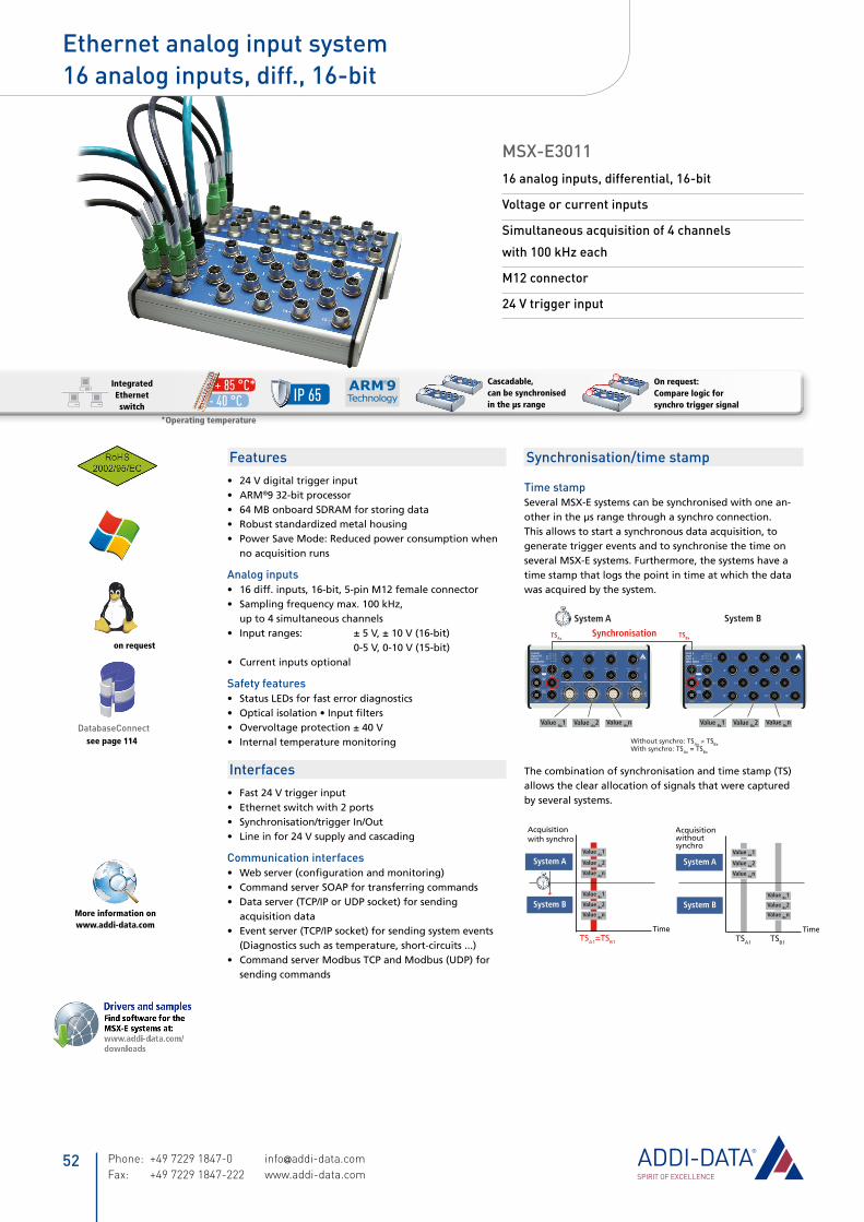
MSX-E301116 analog inputs, differential, 16-bit
Voltage or current inputs
Simultaneous acquisition of 4 channels
with 100 kHz each
M12 connector
24 V trigger input
Features24 V digital trigger input•ARM• ®9 32-bit processor64 MB onboard SDRAM for storing data•Robust standardized metal housing•Power Save Mode: Reduced power consumption when •no acquisition runs
Analog inputs16 diff. inputs, 16-bit, 5-pin M12 female connector•Sampling frequency max. 100 kHz, •up to 4 simultaneous channelsInput ranges: ± 5 V, ± 10 V (16-bit) • 0-5 V, 0-10 V (15-bit)Current inputs optional •
Safety featuresStatus LEDs for fast error diagnostics•Opticalisolation•Inputfilters• Overvoltage protection ± 40 V• Internal temperature monitoring•
InterfacesFast 24 V trigger input•Ethernet switch with 2 ports•Synchronisation/trigger In/Out•Line in for 24 V supply and cascading•
Communication interfacesWebserver(configurationandmonitoring)•Command server SOAP for transferring commands•Data server (TCP/IP or UDP socket) for sending •acquisition dataEvent server (TCP/IP socket) for sending system events •(Diagnostics such as temperature, short-circuits ...)Command server Modbus TCP and Modbus (UDP) for •sending commands
Synchronisation/time stamp
Time stampSeveral MSX-E systems can be synchronised with one an-other in the µs range through a synchro connection. This allows to start a synchronous data acquisition, to generate trigger events and to synchronise the time on several MSX-E systems. Furthermore, the systems have a time stamp that logs the point in time at which the data was acquired by the system.
CounterDigital I/OSystem
MSX-E1701
CH0 CH1 CH2 CH3 CH4 CH5 CH6 CH7
Counter 0 Counter 2 Counter 3Counter 1
CH8 CH9 CH10 CH11 CH12 CH13 CH14 CH15
Dig
ital
I/O
Co
un
ter
AnalogInputSystem
MSX-E3011
System BSystem A
Value Ax1 Value Ax2 Value Axn Value Bx1 Value Bx2 Value Bxn
Without synchro: TSAx ≠ TSBxWith synchro: TSAx = TSBx
SynchronisationTSAxTSBx
The combination of synchronisation and time stamp (TS) allows the clear allocation of signals that were captured by several systems.
Acquisitionwithoutsynchro
Value Ax1
Value Ax2
Value Axn
Time
System B
System A
TSA1
Value Bx1
Value Bx2
Value Bxn
TSB1
Value Ax1
Value Ax2
Value Axn
Value Bx1
Value Bx2
Value Bxn
Time
Acquisitionwith synchro
System B
System A
TSA1=TSB1
IP 65
Temperaturbereich-40 °C bis 85 °C
Temperaturbereich-40 °C bis 85 °C
Kaskadierbar
Synchronisierbarin µs-Bereich
Mehr Info aufwww.addi-data.com
Schutzart IP 65
KaskadierbarEdelstahl
Synchronisierbarin µs-Bereich
Edelstahl
Temperaturbereich-40 °C bis 85 °C
Temperaturbereich-40 °C bis 85 °C
Kaskadierbar
Synchronisierbarin µs-Bereich
Mehr Info aufwww.addi-data.com
Schutzart IP 65
KaskadierbarEdelstahl
Synchronisierbarin µs-Bereich
Edelstahl
Cascadable, can be synchronised in the µs range
On request: Compare logic for synchro trigger signal
on request
see page 114DatabaseConnect
More information on www.addi-data.com
Temperaturbereich-40 °C bis 85 °C
Temperaturbereich-40 °C bis 85 °C
Kaskadierbar
Synchronisierbarin µs-Bereich
Mehr Info aufwww.addi-data.com
Schutzart IP 65
KaskadierbarEdelstahl
Synchronisierbarin µs-Bereich
Edelstahl
- 40 °C + 85 °C*Integrated
Ethernet switch
*Operating temperature
Phone: +49 7229 1847-0 [email protected] Fax: +49 7229 1847-222 www.addi-data.com
52
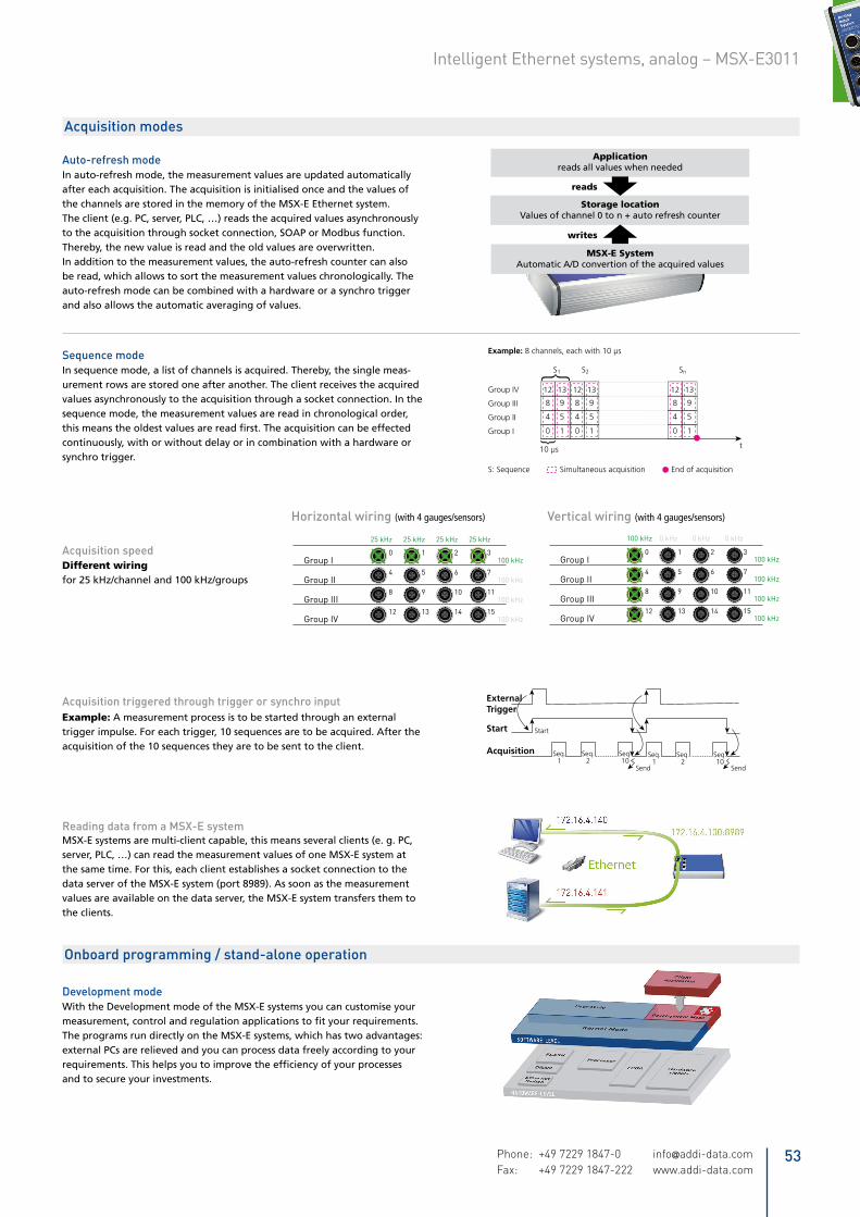
Auto-refresh modeIn auto-refresh mode, the measurement values are updated automatically after each acquisition. The acquisition is initialised once and the values of the channels are stored in the memory of the MSX-E Ethernet system. The client (e.g. PC, server, PLC, …) reads the acquired values asynchronously to the acquisition through socket connection, SOAP or Modbus function. Thereby, the new value is read and the old values are overwritten. In addition to the measurement values, the auto-refresh counter can also be read, which allows to sort the measurement values chronologically. The auto-refresh mode can be combined with a hardware or a synchro trigger and also allows the automatic averaging of values.
Acquisition modes
Applicationreads all values when needed
reads
writes
Storage locationValues of channel 0 to n + auto refresh counter
MSX-E SystemAutomatic A/D convertion of the acquired values
Sequence modeIn sequence mode, a list of channels is acquired. Thereby, the single meas-urement rows are stored one after another. The client receives the acquired values asynchronously to the acquisition through a socket connection. In the sequence mode, the measurement values are read in chronological order, thismeanstheoldestvaluesarereadfirst.Theacquisitioncanbeeffectedcontinuously, with or without delay or in combination with a hardware or synchro trigger.
Development modeWith the Development mode of the MSX-E systems you can customise yourmeasurement,controlandregulationapplicationstofityourrequirements.The programs run directly on the MSX-E systems, which has two advantages:external PCs are relieved and you can process data freely according to yourrequirements.Thishelpsyoutoimprovetheefficiencyofyourprocessesand to secure your investments.
Example: 8 channels, each with 10 µs
t
0
4
8
12
0
4
8
12
1
5
9
13
1
5
9
13
1
5
9
13
0
4
8
12
S1
10 µs
S2 Sn
Group IV
Group III
Group II
Group I
Simultaneous acquisition End of acquisitionS: Sequence
ExternalTrigger
Start
Acquisition
Start
Seq.1
Seq.2
Seq.10
Seq.1
Seq.2
Seq.10
Send Send
Onboard programming / stand-alone operation
Acquisition triggered through trigger or synchro inputExample: A measurement process is to be started through an external trigger impulse. For each trigger, 10 sequences are to be acquired. After the acquisition of the 10 sequences they are to be sent to the client.
Reading data from a MSX-E systemMSX-E systems are multi-client capable, this means several clients (e. g. PC, server, PLC, …) can read the measurement values of one MSX-E system at the same time. For this, each client establishes a socket connection to the data server of the MSX-E system (port 8989). As soon as the measurement values are available on the data server, the MSX-E system transfers them to the clients.
Group I
Group II
Group III
Group IV
Vertical wiring
0 1 2 3
4 5 6 7
8 9 10 11
12 13 14 15
100 kHz 0 kHz 0 kHz 0 kHz
100 kHz
100 kHz
100 kHz
100 kHz
Group I
Group II
Group III
Group IV
25 kHz 25 kHz 25 kHz 25 kHz
100 kHz
100 kHz
100 kHz
100 kHz
Horizontal wiring
0 1 2 3
4 5 6 7
8 9 10 11
12 13 14 15
PLD
AE 1
AE 2
AE 3
AE 4
Simultanous Acquisition
ADC
ADC
PLD
ADC + MultiplexerSequential Acquisition(Multiplex)
AE 1
AE 2
AE 3
AE 4
1 2 3 4 | 1 2 3 4
Sequence Sequence1
2
3
4
1
2
3
4
1
2
3
4
Acquisition speedDifferent wiringfor 25 kHz/channel and 100 kHz/groups
Horizontal wiring (with 4 gauges/sensors)
Group I
Group II
Group III
Group IV
Vertical wiring
0 1 2 3
4 5 6 7
8 9 10 11
12 13 14 15
100 kHz 0 kHz 0 kHz 0 kHz
100 kHz
100 kHz
100 kHz
100 kHz
Group I
Group II
Group III
Group IV
25 kHz 25 kHz 25 kHz 25 kHz
100 kHz
100 kHz
100 kHz
100 kHz
Horizontal wiring
0 1 2 3
4 5 6 7
8 9 10 11
12 13 14 15
PLD
AE 1
AE 2
AE 3
AE 4
Simultanous Acquisition
ADC
ADC
PLD
ADC + MultiplexerSequential Acquisition(Multiplex)
AE 1
AE 2
AE 3
AE 4
1 2 3 4 | 1 2 3 4
Sequence Sequence1
2
3
4
1
2
3
4
1
2
3
4
Vertical wiring (with 4 gauges/sensors)
53Phone: +49 7229 1847-0 [email protected] Fax: +49 7229 1847-222 www.addi-data.com
Intelligent Ethernet systems, analog – MSX-E3011
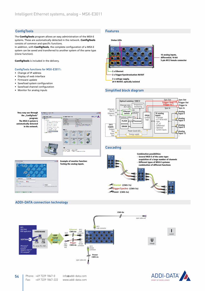
EthernetPort 0
Ethernet Link /ACT LEDs
MIIInterface
FLASH
DRAM
EthernetPort 1
Power Good LED
Trigger OutSync Out
Trigger InTrigger InTrigger Out
Sync In
Sync Out
Sync In
16 analoginputs- 4 groups- 4 x 16-bit ADC- Gain x1, x2- Differential- Optional: current inputs
Analoginput 0
Analoginput 4
Analoginput 8
Analoginput 12Energy supply
Optical isolation 1000 V
Processor
FPGAcontrollogic
Ethernetswitch
Outputline
Processor status LED
Inputline
Temperaturemonitoring
24 Vsupply
2 x voltage supply, 24 V IN/OUT, optically isolated
2 x Trigger/Synchronisation IN/OUT
2 x Ethernet
Status LEDs
16 analog inputs, differential, 16-bit5-pin M12 female connector
digital24 V
digital5 V
currentI
sensorICP
thermocoupleelement
voltageU
temperature
NTC
24 Vdig. input
NPNC
EB
Pt100
HBinductive
transducer
LVDTinductive
transducer
VLDTinductive
transducer
serialRS232
serialRS422
serialRS485
serialTTY
SSI
incremental
A
B
PWM 1 VPP
A
B
Sin
Cos
11 µAPP
A
B
Sin
Cos
DMS
CMX-8x
24 VDC In 24 VDC Out
PowerSupply
Trig/Sync OutTrig/Sync In
Trigger/Sync
Port 1Port 0
Ethernet
15 –14 –13 –12 –
11 –10 –9 –8 –
7 –6 –5 –4 –
3 –2 –1 –0 –Power On
Port 0 ACT/Link
Port 1 ACT/Link
Status
AnalogInputSystem
PowerCMX-2x
RJ45
EthernetCMX-6x
M12male
connector
CMX-4xopencableend
M12female
connector
Trigger
open cable end
M12femaleconnector
PC, server, PLC, HMI ...
HARDWARE
UDPTCP/IP
SOAP
MESdata baseMSR application
IPEmotion®
procella®
SIMATIC STEP 7®
SPC.kompakt®
SOFTWARE
open cable end
M12male connector
ConfigToolsThe ConfigTools program allows an easy administration of the MSX-E systems. These are automatically detected in the network. ConfigTools consistsofcommonandspecificfunctions.In addition, with ConfigTools,thecompleteconfigurationofaMSX-Esystem can be saved and transferred to another system of the same type (clone function).
ConfigTools is included in the delivery.
ConfigTools functions for MSX-E3011:Change of IP address•Display of web interface•Firmware update•Save/loadsystemconfiguration•Save/loadchannelconfiguration•Monitor for analog inputs•
Example of monitor function:Testing the analog inputs.
MultifunctionSystem
Power On
Port 0 ACT/Link
Port 1 ACT/Link
Status
Port 0
Trig/Sync In Trig/Sync Out
24 VDC In 24 VDC Out
Port 1
Ethernet
Trigger/Sync
PowerSupply 1
MultifunctionSystem
Power On
Port 0 ACT/Link
Port 1 ACT/Link
Status
Port 0
Trig/Sync In Trig/Sync Out
24 VDC In 24 VDC Out
Port 1
Ethernet
Trigger/Sync
PowerSupply 2
MultifunctionSystem
Power On
Port 0 ACT/Link
Port 1 ACT/Link
Status
Port 0
Trig/Sync In Trig/Sync Out
24 VDC In 24 VDC Out
Port 1
Ethernet
Trigger/Sync
PowerSupply ...Ethernet (CMX-7x)
Trigger/Synchro (CMX-5x)
Power (CMX-3x)
Simplified block diagram
Cascading
Combination possibilities:- Several MSX-E of the same type: acquisition of a large number of channels- Different types of MSX-E systems: combination of different functions
Features
ADDI-DATA connection technology
Very easy use through the „ConfigTools“
program; The MSX-E system is
automatically detected in the network.
Phone: +49 7229 1847-0 [email protected] Fax: +49 7229 1847-222 www.addi-data.com
54
Intelligent Ethernet systems, analog – MSX-E3011

Ordering information
MSX-E3011Ethernetanaloginputsystem,16analoginputs,diff.,16-bit.Incl.technicaldescription,softwaredriversandConfigTools.
Connection cablesVoltage supplyCMX-2x: Shielded cable, M12 5-pin female connector/open end, IP 65CMX-3x: For cascading, shielded cable, M12 5-pin female connector/male connector IP 65Trigger/SynchroCMX-4x: Shielded cable, M12 5-pin female connector/open end, IP 65CMX-5x: For cascading, shielded cable, M12 5-pin female connector/male connector IP 65EthernetCMX-6x: CAT5E cable, M12 D-coded male connector/RJ45 connectorCMX-7x: For cascading, CAT5E cable, 2 x M12 D-coded male connector
Connection to peripheralsCMX-8x: Shielded cable, M12 5-pin male connector/open end, IP 65
Options
PC-Diff: Current input 0(4)-20 mA for 1 input, diff. (please indicate the number of channels)S7 Modbus TCP Client Library for S7: Easy use of the Ethernet systems MSX-E with PLCsMSX-E 5V-Trigger: Level change of the trigger inputs and outputs to 5 V MX-Clip, MX-Rail (please specify when ordering!), MX-Screw, PCMX-1x
Specifications
Analog inputsNumber/type: 16 differential inputsArchitecture: 4 groups of 4 channels each 4-port simultaneous converter with one 4-channel multiplexer per converterResolution: 16-bit, SAR ADCAccuracy: ± 1.221 mV typ. (± 4 LSB) ± 2.442 mV max.Relative Accuracy (INL): ± 3 LSB max (ADC)Optical isolation: 1000 V Input ranges: ± 5 V, ± 10 V (16-bit), 0-5 V, 0-10 V (15-bit) software-programmable, current inputs optionalSampling frequency: 25 kHz per channel / 100 kHz max.Gain: x1, x2, software-programmableCommon mode rejection: 80 dB min. DC up to 60 Hz (diff. amplifier)Input impedance (PGA): 109 Ω // 10nF against GNDBandwidth (-3dB): 160 kHz limited through TP filters 16 Hz version with differential filterTrigger: digital input, synchro, software-programmableOffset error: ± 1 LSB (± 305 µV)Gain error: ± 2.5 LSBTemperature drift: 2.3 x Vin + 22.5 (µ V/ °C) typ. Vin: input voltage in Volts (-10 V ≤ Vin ≤ +10 V) In the temperature range: from -40°C to +85°C 4.5 ppm/°C FSR
Voltage supply, Ethernet, Trigger, SynchroThe specifications for the voltage supply, Ethernet, Trigger, Synchronisation and Electromagnetic Compatibility apply to all MSX-E systems. See page 31.
System featuresInterface: Ethernet acc. to specification IEEE802.3Dimensions: 215 x 110 mm x 50 mmWeight: 850 gDegree of protection: IP 65Current consumption at 24 V: 180 mAOperating temperature: -40 °C to +85 °CConnectors for sensorsFor analog inputs 16 x 5-pin M12 female connector
55Phone: +49 7229 1847-0 [email protected] Fax: +49 7229 1847-222 www.addi-data.com
Intelligent Ethernet systems, analog – MSX-E3011
Top Related