


Languages
Pages
Legal


8/7/2019 EPA275 Sediment Control
http://slidepdf.com/reader/full/epa275-sediment-control 1/57
C O N S T R U C T I O N T E C H N I Q U E S F O RS E D I M E N T P O L L U T I O N C O N T R O L
EPA
Victoria
May 1991

8/7/2019 EPA275 Sediment Control
http://slidepdf.com/reader/full/epa275-sediment-control 2/57
i
P R E F A C E
State Environment Protection Policies specify a range of requirements aimed at protecting the many beneficial andindeed vital features of Victoria's waterways. These requirements are legally binding and must be complied with
by all Victorians engaged in activities that impact on surface water environments.
Activities of concern include many common construction projects such as building site preparation, bridge and
road works, drainage and dam works and other similar engineering works. These changes to the physical
environment often result in significant off-site environmental damage and reduced amenity.
The Environment Protection Authority has the role of pursuing and acting against those that pollute the
environment, but it recognises that prevention is better than cure. These guidelines and the associated EPA video
Green Engineering - Simple Solutions to Pollution Control have been produced to assist planners and construction
organisations by providing information about simple but effective solutions to these problems.
I would encourage the responsible planning and construction organisations to incorporate these guidelines in all
relevant permits, contract specifications and internal guidelines in order to entrench good environmental practice
in regular engineering undertakings.
Brian Robinson
Chairman
Environment Protection Authority

8/7/2019 EPA275 Sediment Control
http://slidepdf.com/reader/full/epa275-sediment-control 3/57
C O N T E N T S
PREFACE .................................................................................................................................................. i
1. INTRODUCTION ........ ........ ......... ........ ......... ........ ......... ......... ........ ......... ........ ......... ........ ......... ........ .. 1
2. STANDARDS ..................................................................................................................................... 3
3. GENERAL CONSTRUCTION PRINCIPLES....... ........ ......... ........ ......... ........ ......... ......... ........ ......... ........ ...... 4
4. EARLY PLANNING.............. ......... ........ ......... ........ ......... ......... ........ ......... ........ ......... ........ ......... ........ .. 5
5. CLEARING OF VEGETATION............... ......... ......... ........ ......... ........ ......... ........ ......... ........ ......... ......... ...10
6. BUFFER AREAS OF VEGETATION ........ ......... ......... ........ ......... ........ ......... ........ ......... ........ ......... ......... ...10
7. ESTABLISHING VEGETATION.... ........ ......... ........ ......... ........ ......... ........ ......... ......... ........ ......... ........ ..... 11
8. MULCH ...........................................................................................................................................12
9. EARTHWORKS ........ ......... ........ ......... ........ ......... ......... ........ ......... ........ ......... ........ ......... ........ ......... ..13
10. STOCKPILES.....................................................................................................................................16
11. DUST CONTROL................................................................................................................................17
12. DRAINS, DIVERSIONS & STREAMS ......... ........ ......... ........ ......... ......... ........ ......... ........ ......... ........ ........18
13. WATER DROP OR CHUTE STRUCTURES ........ ......... ........ ......... ........ ......... ........ ......... ........ ......... ......... .. 28
14. DAMS & BASINS........... ......... ........ ......... ........ ......... ........ ......... ........ ......... ......... ........ ......... ........ .... 30
15. SEDIMENT & LITTER TRAYS.... ......... ........ ......... ........ ......... ........ ......... ......... ........ ......... ........ ......... ..... 36
16. WATER TREATMENT........ ......... ........ ......... ......... ........ ......... ........ ......... ........ ......... ........ ......... ......... ...41
17. VEHICLES & ROADS ......... ........ ......... ........ ......... ......... ........ ......... ........ ......... ........ ......... ........ ......... . 42
18. MAINTENANCE & WASTE DISPOSAL.. ......... ........ ......... ........ ......... ........ ......... ......... ........ ......... ........ .....45
GLOSSARY ............................................................................................................................................ 48
REFERENCES ..........................................................................................................................................52

8/7/2019 EPA275 Sediment Control
http://slidepdf.com/reader/full/epa275-sediment-control 4/57
C O N S T R U C T I O N T E C H N I Q U E S F O RS E D I M E N T P O L L U T I O N C O N T R O L
1
1 . I N T R O D U C T I O N
Aquatic ecosystems are easily damaged by erodedsoil and other contaminants from construction
sites, land subdivisions and other areas where
soil is exposed. Water is a scarce resource and it
is important to prevent it being polluted by muddy
sediment wherever possible.
(a) Use of this booklet
This booklet has been prepared for the use of land
development companies, civil engineering
consultants, authorities involved with land useplanning, departments involved with land use
controls and any other interested groups.
With careful planning, the application of the
techniques outlined in this booklet can help protect
the environment at the same time as increasing
construction efficiencies and reducing land
development costs (references 19 and 24).
The quantity of sediment discharged from a site can
often be minimised by a few simple techniqueswhich have many on-site benefits. Many of these
techniques, however, are easily overlooked.
Techniques such as early revegetation often receive a
low priority when there are many other problems to
be solved.
One way to help reduce these problems is to include
definitive pollution controls in construction site
specifications, planning permit conditions, and.
controls by the relevant Government authorities.
The techniques listed in this booklet provide a basis
for such controls.
To increase the chances of success, it is suggested
that financial incentives such as bonuses and
financial bonds or assurances be provided for
adequately completing erosion and sediment
controls.
Detailed design information, such as drainage works
dimensions for different water flow rates, have been
left to the province of more specialised books and
manuals. A key publication for this purpose is
Guidelines for Minimising Soil Erosion and
Sedimentation from Construction Sites in Victoria
(reference 22) available from the Department of
Conservation and Environment.
(b) Advantages of Erosion & Sediment Control
With careful pre-planning, erosion and sediment
control usually result in many on-site advantages in
addition to protecting the environment.
Environmental benefits include:
• reduced risk of damage to aquatic
ecosystems,
• improved appearance of the site and
downstream waters,
• reduced water treatment costs,
• reduced blockage of drains,
• less mud dropped or washed onto roads.
On-site benefits typically include:
• less risk of works being undermined by
erosion or buried by sediment,
• improved drainage and reduced site wetness
as a result,
• less dust problems,
• improved working conditions,
• reduced downtime after rain,
• less stockpile losses,
• reduced dean-up costs,
• earlier works completion,
• earlier land sales,
• less chance of complaints by neighbours.

8/7/2019 EPA275 Sediment Control
http://slidepdf.com/reader/full/epa275-sediment-control 5/57
C O N S T R U C T I O N T E C H N I Q U E S F O RS E D I M E N T P O L L U T I O N C O N T R O L
2
(c) Water pollution
Soil washed from land development sites is usuallydeposited as sediment in streams. This process can
greatly increase the concentration of materials
suspended and dissolved in streams and the
durations and frequencies for which downstream
waters remain turbid.
Water which flows or is pumped from land
disturbance sites can be contaminated by
suspended, dissolved, floatable and settleable soil
materials, oils, detergents, litter, fertilisers, alkaline
cement materials and other chemicals.
Soil nutrients and chemical pollutants become
attached to and are transported by sediment
particles as a result of soil erosion, dewatering of
trenches, washing of vehicles, cleaning of concrete
supply equipment, careless waste disposal and other
similar incidents. Heavy metals and disease
organisms also become attached to, protected by
and transported on sediment particles.
These pollutants reduce the usefulness andenjoyment of the water environment to people
downstream and damage aquatic life in streams,
lakes and estuaries (references 4, 5 and 7).
Muddy sediment can smother stream beds where
aquatic animals live, reproduce and obtain
nourishment. Muddy material suspended in water
can choke and abrade aquatic organisms and their
eggs. Suspended material can also reduce visibility
and the ability of many fish and other organisms to
capture prey. Suspended and coloured materials can
block sunlight and prevent the growth of aquatic
plants (reference 4).
Sediment can fill dams and block waterways and
drains, thereby increasing removal or dredging costs.
Siltation of streams can reduce their capacities to
carry flood waters and increase the risk of flooding as
a consequence.
Muddy material in water can also degrade its
aesthetic appearance.
(d) State Environment Protection Policy
To protect the quality of surface waters, the State
Environment Protection Policy (Waters of Victoria)
has been declared by Government (reference 44).
Under this Policy, controls are needed for
construction and other land disturbance sites to
protect the following beneficial uses of water from
pollution:
• natural aquatic ecosystems and associated
wildlife,
• recreation (swimming, boating and aesthetic
enjoyment),
• agriculture (stock watering and irrigation),
• potable town water supplies,
• production of molluscs for human
consumption,
• edible fish and crustaceans,
• industrial water uses.
The State Environment Protection Policy (Waters of
Victoria) specifies water quality objectives and
provisions to help achieve these objectives. These
provisions include the minimisation of erosion on
construction sites and along roads, streams and
drainage lines. Acts of Parliament which are relevant
to achieving such provisions include the Environment
Protection Act 1970, the Soil Conservation and Land
Utilisation Act 1958, the Planning and Environment
Act 1987, the Local Government Act 1958 and other
Acts which relate to land use and management.
(e) Other pollution problems
Many air, land and noise pollution problems are
often considered at the same time as erosion and
sediment control on land disturbance sites.

8/7/2019 EPA275 Sediment Control
http://slidepdf.com/reader/full/epa275-sediment-control 6/57
C O N S T R U C T I O N T E C H N I Q U E S F O RS E D I M E N T P O L L U T I O N C O N T R O L
3
Soil stabilisation, for example, can reduce both
sediment discharge and the generation of wind
blown dust. Litter screens are often installed as
important components of sediment traps.
Construction activities can result in noise and land
contamination problems.
For these reasons, many relevant aspects of air, land
and noise pollution are outlined in this booklet.
More detailed information about the control of these
problems, however, can be obtained in the
references listed at the end of this booklet.
2 . S T A N D A R D S
The State Environment Protection Policy (Waters of
Victoria) requires that land disturbance activities be
carefully controlled and soil conservation measures
undertaken to minimise soil erosion and subsequent
run-off of suspended, dissolved, floatable and
settleable matter (reference 44).
Fine soil particles such as clays tend to remain
suspended in water and are difficult to remove or
settle out. Soil erosion can therefore result in
streams being polluted by muddy sediment for long
distances.
Environmental and engineering needs are usually
interrelated. Structural stability of sediment trap
dams, for example, is needed to ensure their long
term safety and effectiveness; downstream sediment
pollution can occur if the dams fail (references 2, 8
and 31).
For effective control of soil erosion, sediment
discharge and associated problems, it is therefore
important to use the best management practicesavailable, commonly available technology and
high environmental, safety and engineering
standards.
(a) Suspended solids & turbidity
The State Environment Protection Policy (Waters of
Victoria) specifies water quality objectives for light
penetration or turbidity, suspended solids and
settleable matter such as sediment (reference 44).
Figure 1. Eroded embankment and driveway which havenot been stabilized during early stages in a
housing subdivision area
Figure 2. This sediment from a roadside drain blocks
stormwater pipes and can pollute rivers and
creeks further downstream.

8/7/2019 EPA275 Sediment Control
http://slidepdf.com/reader/full/epa275-sediment-control 7/57
C O N S T R U C T I O N T E C H N I Q U E S F O RS E D I M E N T P O L L U T I O N C O N T R O L
4
A major objective written into this Policy is the
minimisation of soil erosion and the runoff of
suspended, dissolved, floatable and settleable matter
such as sediment.
To help achieve these objectives, it is suggested that
runoff from land disturbance sites not be allowed to
increase suspended solids concentrations in streams
by more than 10% or 10 milligrams per litre, whichever
results in the highest figure. Similarly, water turbidity
should not be increased by more than 10 percent or 10
NTU's (see Glossary), whichever results in the highest
figure. These water quality limits are suggested wherea high level of protection is needed.
Other allowable increases in suspended solids
concentrations and turbidity would need to be chosen
on the basis of factors such as relative catchment
areas, water runoff rates and the environmental
qualities of the waters involved (references 5 and 29).
Water samples and tests to measure suspended
solids increases would typically need to be taken
along a stream just upstream and downstream of alocation where contaminated runoff enters the stream.
Water sampling within any one hour period could be
specified in contract specifications, permits, notices
etc. to provide sufficient sampling time.
In areas where waters have a good or excellent
environmental quality (references 5 and 29), it may be
necessary to prevent any land disturbance activities
which increase sediment discharge rates. The State
Environment Protection Policy (Waters of Victoria), for
example, specifies no variation in water quality from
background levels in aquatic reserves.
It should be noted that, under the Environment
Protection Act 1970, the Environment Protection
Authority may impose specific waste discharge quality
limits on any premises, particularly those which are
scheduled under the Environment Protection
(Scheduled Premises and Exemption) (Amendment)
Regulations: (reference 48).
(b) Water pH
Wastewaters from construction sites are often alkaline(ie: a high pH) where cement and lime are used.
Schedule E of the State Environment Protection Policy
(Waters of Victoria) requires that all waste discharges
are maintained in the pH range of 6.0 to 9.0 pH units
(reference 44).
It should be noted that Schedule B of this Policy
requires that water pH in general surface waters is not
altered from seasonal background levels by more than
1.0 pH value and 0.5 pH values for waters in parks,forests, estuaries and coastal areas.
No variation of pH from background values is allowed
in aquatic reserves.
(c) Other pollutants
It is important to ensure that no scum, foam, grease,
toxic substance, litter, visible oil or floating material
flows from land disturbance sites (Sections 15 to 18).
3. GENERAL CONSTRUCTION PRINCIPLES
This section outlines some of the most important
principles for erosion and sediment control on
construction sites. By including these principles in
contract specifications, planning conditions and other
such requirements, the environment can be protected
in addition to reducing land development costs.
(a) Land Use Intensities
Water pollution can be minimised or avoided by
simply reducing or preventing an increase in land
use intensities. This typically involves the planting or
preservation of trees and other vegetation. Minimising
the areas of land disturbed for residential
development, roads and other facilities can protect
the environment in addition to reducing development
costs (references 24, 33 and 53).
8/7/2019 EPA275 Sediment Control
http://slidepdf.com/reader/full/epa275-sediment-control 8/57
C O N S T R U C T I O N T E C H N I Q U E S F O RS E D I M E N T P O L L U T I O N C O N T R O L
5
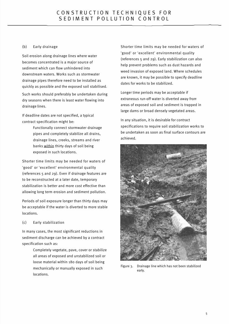
(b) Early drainage
Soil erosion along drainage lines where water becomes concentrated is a major source of
sediment which can flow unhindered into
downstream waters. Works such as stormwater
drainage pipes therefore need to be installed as
quickly as possible and the exposed soil stabilised.
Such works should preferably be undertaken during
dry seasons when there is least water flowing into
drainage lines.
If deadline dates are not specified, a typical
contract specification might be:
Functionally connect stormwater drainage
pipes and completely stabilize all drains,
drainage lines, creeks, streams and river
banks within thirty days of soil being
exposed in such locations.
Shorter time limits may be needed for waters of
'good' or 'excellent' environmental quality
(references 5 and 29). Even if drainage features are
to be reconstructed at a later date, temporary
stabilization is better and more cost effective than
allowing long term erosion and sediment pollution.
Periods of soil exposure longer than thirty days may
be acceptable if the water is diverted to more stable
locations.
(c) Early stabilization
In many cases, the most significant reductions in
sediment discharge can be achieved by a contract
specification such as:
Completely vegetate, pave, cover or stabilize
all areas of exposed and unstabilized soil or
loose material within 180 days of soil being
mechanically or manually exposed in such
locations.
Shorter time limits may be needed for waters of
'good' or 'excellent' environmental quality
(references 5 and 29). Early stabilization can also
help prevent problems such as dust hazards and
weed invasion of exposed land. Where schedules
are known, it may be possible to specify deadline
dates for works to be stabilized.
Longer time periods may be acceptable if
extraneous run-off water is diverted away from
areas of exposed soil and sediment is trapped in
large dams or broad densely vegetated areas.
In any situation, it is desirable for contract
specifications to require soil stabilization works to
be undertaken as soon as final surface contours are
achieved.
Figure 3. Drainage line which has not been stabilized
early.

8/7/2019 EPA275 Sediment Control
http://slidepdf.com/reader/full/epa275-sediment-control 9/57
C O N S T R U C T I O N T E C H N I Q U E S F O RS E D I M E N T P O L L U T I O N C O N T R O L
6
(d) Water diversion
It is important to divert water along stable diversiondrains, banks or bunds around or away from exposed
areas of soil or loose material (see Section 12).
This is often one of the easiest and cheapest ways of
preventing erosion and sediment runoff.
(e) Sediment and litter control
To prevent sediment and other matter flowing into
drainage systems, sediment and litter traps may be
needed. Such structures should be constructed from
heavy duty materials in accordance with Sections 13
and 15. Sediment trap dams and basins should also
be constructed, wherever practicable, downstream
from and prior to earthworks operations.
(f) Delegation
It is important that developers and construction site
workers are aware of all relevant erosion and
pollution control objectives and techniques.
Knowledge and skills in these aspects should be
increased as much as possible, by providing training
sessions and accurate plans and specifications.
Ideally, a specialist person or group with relevant
training or experience should be provided to plan,
advise, supervise, install and maintain erosion and
pollution control works.
(g) Maintenance
All pollution control works should be inspected on aregular basis and maintained or repaired to ensure
their ongoing effectiveness. At these times, reassess
their operation and improve their effectiveness
wherever possible.
4 . E A R L Y P L A N N I N G
Consideration of erosion and sediment controls
during early planning stages is important to minimise
their cost and maximise their effectiveness.
(a) Prior planning
Erosion and sediment control plans, specificationsand schedules for development sites should be
prepared prior to the commencement of works and
submitted to the relevant groups.
Relevant information about the area such as soil
characteristics, geology and land capability maps
should be obtained at the earliest stages.
When planning finance and labour needs, it is
important to allow for erosion and sediment controls
additional to usual contingency allowances.
Figure 4. Drainage line and hillside which have beenstabilized during early construction stages.
(b) Avoid sensitive areas
Wide buffer areas of dense vegetation need to be
provided along the margins of streams, drainage
lines and other surface water features (Section 6).
Excavations or earthworks should be confined to
land with gradients less than 20% (5:1 horizontal:
vertical) and preferably less than 8% (reference 33).
Avoid works which increase landslip risks and avoid
disturbing environmentally sensitive areas.

8/7/2019 EPA275 Sediment Control
http://slidepdf.com/reader/full/epa275-sediment-control 10/57
C O N S T R U C T I O N T E C H N I Q U E S F O RS E D I M E N T P O L L U T I O N C O N T R O L
7
Maps showing land capability ratings, vegetation
types, stream values etc. can help to identify
sensitive areas (see references).
(c) Site plans
Site plans of the 'premises should be drawn to scale
showing existing and proposed works, site gradients,
closely spaced contour lines, drainage systems,
easements, boundaries, direction, permanent survey
marks, scale(s) and other relevant features, prior to
undertaking works.
Figure 5. Erosion and sediment control plans should bepart of every construction phase.
(d) Catchment plans
Location plans should be prepared or aerial
photographs marked to show the premises,
catchment boundaries, gradients, land uses, soil
types, landslip risks, flood zones and other relevant
features prior to undertaking works.
(e) Tenders & Permit Applications
There are many topics relevant to erosion and
sediment control which are not included in this
booklet, which should be outlined in project
specifications, planning permit applications, tenders
etc. It is suggested that the following sections be
considered for inclusion in such applications:
• project description,
• schedules,
• location plans,
• land capability,
• erosion & sediment controls,
• noise control,
• flora, fauna & aquatic life,
• maintenance & waste disposal,
• financial budgets & bonds,
• training & supervision
• plans showing –
allotments & easements existing &
proposed works existing & proposed
contours site drainage & gradients land
capabilities & soil types landslip risks
existing & proposed vegetation
catchment characteristics buffer areas
& nearby landuses earthworks,
stockpiles etc erosion & sediment
controls,
• works cross sectional drawings,
• water discharge calculations.
(f) Subdivisions & works layout
Developments should ideally be designed to conform
to existing land contours in ways which minimise soil
exposure and potential soil erosion and sediment
discharge rates.
Wherever practicable, roads and buildings should belocated on gently sloping land along or near
ridgelines or where there is least risk of soil erosion.
Locating roads so they follow actual land contours
can also minimise earthworks and erosion risk.
Wherever possible, roads should not be located
along drainage lines where the risks of soil erosion
and sediment pollution are high. In general, steep
land with terrain that requires such road locations
should not be chosen for subdivision development.

8/7/2019 EPA275 Sediment Control
http://slidepdf.com/reader/full/epa275-sediment-control 11/57
C O N S T R U C T I O N T E C H N I Q U E S F O RS E D I M E N T P O L L U T I O N C O N T R O L
8
Allotment boundaries should coincide with
streamside buffer boundaries and allow easy access
to streams in case erosion controls or other such
works are needed in the future. Subdivision
boundaries across drainage lines and streams
should also be prevented or minimised to provide
easy access for erosion controls if needed in the
future.
(g) Water discharge calculations
To minimise the risk of drainage works being
overtopped by water and soil being eroded, it is
important to calculate peak water flow rates and
velocities.
These should be calculated for standard design
stormwater recurrence intervals for all drainage and
sediment control works. The recurrence intervals
needed depend on the situations and may vary from
about one year for temporary works where there are
low environmental risks to 100 or more years for
permanent works in areas with high environmental
risks. References 22 and 25 list typical recurrence
intervals.
Figure 6. Typical construction site plan showing erosion
and sediment controls.

8/7/2019 EPA275 Sediment Control
http://slidepdf.com/reader/full/epa275-sediment-control 12/57
C O N S T R U C T I O N T E C H N I Q U E S F O RS E D I M E N T P O L L U T I O N C O N T R O L
9
Table 1. Summary of erosion and sediment controls: water erosion in general, sheet and rill erosion.
Definitions Main Causes Typical Solutions Key Sections
(in this
booklet)
Water erosion in
general
Erosion is defined as
the detachment or
wearing away of materials such as soil.
Water erosion can
occur in various forms
such as sheet,raindrop splash, rill,
gully, channel sideand channel bed
erosion. Tunnel
erosion and landslipsare also relevant.
These can occur in
varying combinationswith one form
predominating. More
detailed information iscontained in Tables 2
to 5.
The forces imposed by
flowing water which
increase as water velocities or flow rates
increase.
Reducing or preventing an increase in land
use intensities.
Reductions in water flow rates or velocitiessuch as by:
• diversion of water to stable locations,
• increasing water infiltration into the soil
by deep ripping or revegetation,• increasing water use in catchments by
growing vegetation, or • conversely, by minimising
• the area which is hard paved,
• providing wide buffer areas of • dense vegetation alongside
• streams & other water features,
• installing flood detention dams.
Well supported retaining walls, subsurface
drains &/or tree planting to hold steep land
such as occurs along hillside cuttings.
Protection of exposed soil with dense
vegetation or material such as crushed rock
or pavement
Sediment trap dams or structures
Water treatment or filtration
1 to 10,
12 to 18
Sheet & rill erosionSheet erosion is the
relatively uniform
removal of soil or material from an area
without conspicuous
channel formation.
Rills are eroded
channels less than
300 mm deep.
Water flowing across
& removing exposed
soil.
Rates of sheet & rill
erosion are increased
by the turbulencecreated by rainfall.
Raindrop splash also
dislodges & transportssoil downhill.
Establishment of dense vegetation.
Other solutions as listed above.
6 to 9

8/7/2019 EPA275 Sediment Control
http://slidepdf.com/reader/full/epa275-sediment-control 13/57
C O N S T R U C T I O N T E C H N I Q U E S F O RS E D I M E N T P O L L U T I O N C O N T R O L
10
5 . C L E A R I N G O F V E G E T A T I O N
Many erosion and sediment control problems can beavoided by maximising the areas of vegetation
retained and by careful clearing techniques.
Such strategies should be considered during early
planning stages.
(a) Clearing controls
Under planning schemes and other government
legislation, the clearing of vegetation may not be
possible without permits, licences or approvals from
the responsible government authorities.
A permit may need to be obtained from the local
municipal council, for example, for the clearing,
removal, destruction or lopping of native vegetation.
Controls may also be required under the Flora and
Fauna Guarantee Act 1998, the Code of Forest
Practices for Timber Production and the Timber
Harvesting Regulations 1989 (references 9, 50 and
51). The preparation of clearing, revegetation and
environment protection plans, outlines and
schedules may assist in the provision of appropriate
permits or approvals to clear vegetation.
(b) Minimise or prevent clearing
To minimise the risk of soil erosion and sediment
pollution, existing vegetation should be retained
wherever feasible.
The preservation of vegetation is particularly
important on steep land or in buffer areas along
drainage lines where the risks of soil erosion are
greatest. Vegetation needs to be protected in and
around environmentally significant waterbodies such
as wetlands. Vegetation may also need to be
preserved in catchments to streams of high or
excellent environmental value to protect aquatic
ecosystems (references 5 and 293.
If it is necessary to clear vegetation; the area cleared
at any one time should be minimised.
(c) Windrows
Windrows of cleared vegetation should be placedalong the contour rather than directly up and down
slopes. This approach tends to assist in the trapping
of sediment.
(d) Burning off
Wherever possible, convert cleared vegetation into
mulch or sawn logs rather than burning it on the
premises. If burning materials on the premises, abide
by local municipal laws and EPA guidelines.
(e) Rough cultivation
After clearing vegetation, it may be desirable to leave
the soil surface in a rough condition or cultivate so as
to leave large clods of soil. This will increase the
infiltration of water into the soil and reduce water
runoff and soil erosion as a result. Contour or across-
slope ripping can also reduce water run-off rates.
6 . B U F F E R A R E A S O F
V E G E T A T I O N
Wide buffer areas of dense vegetation around
development sites and along streams can
significantly reduce water, air and noise pollution.
(a) Premises boundaries
The planting of appropriate types of trees in buffer
areas preferably wider than 30 metres around the
boundaries of premises can often improve visual
appearances in addition to controlling sediment and
dust pollution.
(b) Drainage features
Wherever possible, establish and maintain buffers of
dense grasses or ground cover vegetation at least 30
metres wide alongside drainage lines and other
surface water features. Such buffer areas can help
prevent soil erosion in addition to trapping sediment
and other pollutants.

8/7/2019 EPA275 Sediment Control
http://slidepdf.com/reader/full/epa275-sediment-control 14/57
C O N S T R U C T I O N T E C H N I Q U E S F O RS E D I M E N T P O L L U T I O N C O N T R O L
11
Streamside buffer areas may not be possible for
some high intensity landuses such as urban
development. In such areas, stable drainage works
should be completed as early as possible.
In pristine areas such as dense natural bushland, it
may not be possible to prevent damage to aquatic
ecosystems if buffer areas are less than 100 or even
several hundred metres wide. To protect streams of
high or excellent environmental value (references 5
and 29), it may be desirable to prevent any increases
in land use intensities throughout the catchments to
these streams.
(c) Mark vegetation boundaries
Boundaries for buffer areas and areas for vegetation
establishment or protection are often difficult to
identify during works operations. This can be
overcome by using painted pegs, rip lines, fences,
signs, coloured ribbons, spray paint lines or other
obvious markers about which site workers have been
previously advised.
7 . E S T A B L I S H I N G V E G E T A T I O N
Establishing or preserving dense vegetation is often
the cheapest way of preventing soil erosion and
sediment pollution. Checking on the range of
different plants available and assessing their growth
requirements can greatly improve the chances of
success.
(a) Vegetation requirements
The establishment requirements of plants need to be
identified prior to commencing site works. Relevant
factors include local climate, soil nutrient levels, site
wetness and soil pH.
(b) Topsoil & mulch
Plants grow better in loamy topsoil than clayey
subsoil. To assist plant establishment, spread loamy
topsoil on all exposed areas of subsoil where
vegetation is to be established and soil amelioration
is not planned to be used. The subsoil should be
contour ripped or scarified to assist plant
establishment.
(c) Minimise fertilisers
If fertilisers are used, they should be applied at the
minimum rates required, and mixed or combined
with the surface layers of soil or mulch. Prevent the
drift of fertilisers across streams,
drains or other locations where
water pollution may result. Along
streambanks, high application
rates of appropriate seed types
and resowing if and when
needed, can often compensate for
a lack of fertiliser.
The need for nitrogen fertilisers
can be avoided by sowing
nitrogen fixing legumes such as
clovers to assist grass
establishment. Additional
information about plant nutritioncan be found in references 3, 6
and 10.
Figure 7. Grass has fibrous roots to hold the soil andflexible leaves to absorb rain impact.
(d) Temporary vegetation
When a temporary cover of vegetation is required,
consider the use of a cereal cover crop for rapid
establishment. Resow or undersow cover crops with
suitable plant species where soil protection isrequired for more than one year. Use vigorous
growing but non-competitive plant species where a
temporary cover of vegetation is required prior to
establishing native plant species.
(e) Establish vegetation early
Establish dense vegetation as soon as practicable on
all areas of exposed soil for w hich other stabilization
techniques or sediment trap devices are not
completed.

8/7/2019 EPA275 Sediment Control
http://slidepdf.com/reader/full/epa275-sediment-control 15/57
C O N S T R U C T I O N T E C H N I Q U E S F O RS E D I M E N T P O L L U T I O N C O N T R O L
12
As a “rule of thumb”, dense vegetation should be
established, even if temporary, within 180 days of
soil being exposed and not further excavated or
covered (see Section 1).
Longer establishment times may be required for
native vegetation. Even so, cereal cover crops can be
used to provide temporary soil protection while
undersown native plants become established.
If areas becomes too boggy for mechanical sowing or
planting techniques, it should be noted that manual
techniques are often possible.
Grass sods or sprigs, irrigated during dry periods, can
provide an immediate cover of vegetation.
(f) Irrigation
Areas which are newly sown to grass or planted with
seedlings should be irrigated during excessively dry
periods to help achieve dense plant growth.
This can help to provide a protecting soil cover prior
to possible erosive rainstorms and is particularly
important on steep land or wherever water run-off becomes concentrated. This approach can reduce the
need for resmoothing of rifled surfaces after
rainstorms and the use of expensive mulch and
netting. It can also avoid expensive resowing if
rainstorms wash away unprotected seed and
fertiliser.
Irrigation from dams, streams, springs or truck water
tankers may be possible if reticulated water is not
otherwise available. A water tanker holding 20,000
litres of water, for example, can irrigate one hectare
to a depth of 2mm. Four or so irrigations can provide
the equivalent of a gentle rainfall of 8mm. Pumps
and rotating spray irrigators attached to water
tankers are commercially available.
(g) Trees and bushes along gullies
When trees or bushes are used to stabilize eroded
gullies, they usually need to be planted alongside
each other on each side of the gully.
This helps prevent water being deflected around
individual trees and initiating gully side erosion.
(h) Plant damage
Trees and bushes are easily killed by soil excavation
or deposition. Excavations or fill material can alter
water drainage patterns and water table heights.
This can result in waterlogging or soil drying and
death of the plants.
Soil compaction, oil or chemical spillages and direct
damage to trunks, branches or roots can also result
in plant death. Solutions to these problems areoutlined in references 13, 22 and 41.
8 . M U L C H
Thin layers of mulch are needed to conserve soil
moisture and assist plant growth. Thick layers of
mulch material can be useful where needed to
suppress weed or other plant growth and to help
protect soil from erosion.
(a) Mulch types
Mulch materials include straw, hay, gravel, paper
mache fibres, wood fibres in plastic mesh, sugar
cane fibre matting, chipped tree branches, coarse
wood shavings and tan bark. Thin layers of mulch are
particularly needed where vegetation is to be
established but topsoil is absent from soil surfaces
or where batters are steeper than 3:1
(horizontal:vertical).
(b) Mulch stability
Thin layers of mulch can be displaced by wind or
stormwater. This can be prevented by holding down
the mulch by a material such as plastic mesh or
possibly by crimping the mulch into topsoil with
cleated rollers or bulldozer tracks.
Bitumen is sometimes useful for holding down
mulch. If bitumen or other adhesive liquids are used,
they should be applied in ways which do not pollute

8/7/2019 EPA275 Sediment Control
http://slidepdf.com/reader/full/epa275-sediment-control 16/57
C O N S T R U C T I O N T E C H N I Q U E S F O RS E D I M E N T P O L L U T I O N C O N T R O L
13
water, drift onto neighbouring properties or cause a
public nuisance.
Plastic mesh can be useful to hold down mulch until
plants become established because it breaks up
under the influence of sunlight. Steel mesh, however,
can become a safety hazard when loose and rusted.
If steel mesh is used to hold down mulch, it should
be removed when grass becomes established to
allow the growth of trees without trunk damage.
Loose mulch should have gentle surface gradients to
prevent it being washed away during heavy
rainstorms. Wherever possible, divert extraneous
water around or away from mulched areas to prevent
the mulch being washed away.
(c) Mulch storage
Avoid storing mulch in thick layers to prevent
decomposition and resultant heat build up and the
risk of spontaneous combustion. Decomposition and
combustion of mulch materials can result in fire
risks, offensive odours and air pollution. Keeping the
mulch dry can also help to prevent these problems.
Typical solutions include the use of tarpaulins and
enclosed composting bins.
Figure 8. Chopped straw and bitumen being blown onto abatter. Care is needed to prevent bitumen
drifting onto nearby property.
9 . E A R T H W O R K S
In general, earthworks should be stabilized as earlyas possible to minimise the risk of soil erosion and
sediment pollution.
(a) Protect exposed soil
The following controls are needed where sediment
trap structures are not available and soil is to remain
exposed for more than a few months or vegetation is
difficult to establish:
• divert extraneous water runoff away from
exposed soil,
• contour plough or deep-rip so as to leave a
rough cloddy surface,
• provide protective covers, and/or
• construct gently sloping diversion banks at
frequent intervals (see Section 12h).
(b) Dry season work
Whenever possible, confine earthworks operations,
particularly those along drainage lines, to months
which have least average rainfall and hence, lowestrisks of soil erosion.
(c) Wet season work
During winter months, confine earthworks to
locations where there is a low risk of soil erosion and
sediment discharge from the premises. This
approach can also avoid waterlogging problems.
(d) Staged earthworks
Wherever practicable, work in staged sections so thatno more than a specified area of soil is disturbed or
exposed at any one time.
(e) Soil testing & treatment
Soil tests are often advisable to assess the erodibility
of soil and its suitability for establishing vegetation.
Agricultural lime, for example, may be needed for
effective plant establishment if the soil is acidic.
Poorly structured clayey soil may need gypsum or
suitable organic matter to make it more friable.

8/7/2019 EPA275 Sediment Control
http://slidepdf.com/reader/full/epa275-sediment-control 17/57
C O N S T R U C T I O N T E C H N I Q U E S F O RS E D I M E N T P O L L U T I O N C O N T R O L
14
Slaked lime may need to be carefully mixed into
subsoil to reduce soil erodibility and improve its
engineering characteristics. Cement can also be
mixed into soil to reduce its erodibility and to provide
a more solid surface. Pollution of runoff water should
be prevented, such as by thoroughly mixing lime and
cement into soil, adding water then compacting the
soil to good standards.
(f) Batters
Batters (see Glossary) need to be constructed at
stable gradients to prevent land slip. The slippage of
steep land into drains can be a major source of
sediment pollution. Stable gradients depend on soil
types, batter heights and subsurface drainage and
vary from 1:1 to less than 4:1 (horizontal:vertical). The
gradients and design of dam embankment batters
are detailed in references 22 and 31.
Gently sloping berms or benches are often needed to
increase the stability of batters higher than about six
metres. Berms or benches should be free draining
and not contain depressions where water ponds.Pondage of water can result in landslip or tunnel
erosion. Soil compaction and paved drains may also
reduce these problems.
The advice of geotechnical consultants may be
needed for batters higher than about six metres or
batters in dangerous or difficult situations.
(g) Topsoil
Plants grow better in loamy topsoil than in clayey
subsoil with little organic matter. Exposed subsoil
should be contour ripped or scarified to assist plant
establishment and to reduce topsoil slippage or
erosion. Where practicable, spread topsoils from
areas being excavated directly onto previously
completed earthworks. This can reduce costs, reduce
damage to plant seeds in the topsoil and result in
earlier stabilization. Otherwise stockpile or transport
topsoils separately from subsoils for later
respreading or use.
(h) Topsoiling batters
Rip, scarify, step or otherwise roughen earthenbatters which are to be stabilized with vegetation
and are steeper than 3:1 (horizontal:vertical). This is
needed to increase the penetration of plant roots and
help prevent topsoil slipping downhill. Spread loamy
topsoil 70 to 100 millimetres thick on such batters.
Thicker layers of topsoil tend to slip off steep batters.
“Rounding off” batter crests and toes can further
reduce the chance of erosion and makes mowing
easier.
Figure 9. Techniques for retaining topsoil on batters.

8/7/2019 EPA275 Sediment Control
http://slidepdf.com/reader/full/epa275-sediment-control 18/57
C O N S T R U C T I O N T E C H N I Q U E S F O RS E D I M E N T P O L L U T I O N C O N T R O L
15
Table 2. Summary of erosion and sediment controls: tunnel erosion & landslips.
Definitions Main Causes Typical Solutions Key Sections
(in this
booklet)
Tunnel erosion
Tunnel erosion is theremoval of subsoil by
water while the
surface soil remainsintact.
Concentrations of water flowing through
holes or cracks in the
subsoil.
Concentrations of
subsoil water can
result in the
progressive sloughingor sapping of subsoil
which creates atunnel progressively
eroding uphill.
Ripping and compaction of soil into tunnelsplus water diversion to stable locations.
Impermeable barriers such as compacted
clay plugs may be needed to prevent water flowing along large tunnels. These should
be deeply entrenched into the tunnel sides
& floor.
Diversion drains or banks should be check
surveyed at completion to ensure that water
does not pond & cause more tunnelerosion. Paving of diversion drains may also
reduce this problem.
Control of burrowing animals such asrabbits
7. 9, 12
Landslip or mass
movementCollapse or downhill
slippage or movementof soil, rock, or other
material.
This can be asignificant source of
sediment pollution
when the materialcollapses into
streams or other
drainage lines.
Land or
embankments withgradients steeper
than their natural
angle of repose.
Concentrations of
subsoil moisture
which lubricate thesoil & exert increased
water pressures
within soil pores andcracks.
Undermining which
results in materialcollapse due to
gravity.
Deep rooted vegetation.
Subsoil drainage.
Well buttressed or entrenched retaining
walls with subsurface drainage works.
(Sloping of retaining walls uphill can resistdownhill movement).
Diversion of surface waters to stable
locations.
Batter gradients less steep than their
natural angle of repose.
Pavement above embankments may helpdivert water & prevent water infiltration into
slip prone material.
9. 12

8/7/2019 EPA275 Sediment Control
http://slidepdf.com/reader/full/epa275-sediment-control 19/57
C O N S T R U C T I O N T E C H N I Q U E S F O RS E D I M E N T P O L L U T I O N C O N T R O L
16
Figure 10. Batter scarified across-slope to trap topsoil and
assist grass establishment
(i) Steep batters
It is usually difficult to retain topsoil on batters
steeper than 2:1 (horizontal:vertical). On steepbatters, topsoil can be retained by installing
horizontal boards, mesh, branches, logs or other
suitable material held and secured by vertical stakes,
rods or other methods. Fibre mesh or mulch pinned
firmly onto batters can also help to trap topsoil.
(j) Retaining walls
Retaining walls need to be constructed to good
engineering standards with adequate drainage and
foundation or buttress support. This is particularlyimportant where batters are higher than about two
metres and steeper than 2:1 (horizontal vertical), or
otherwise unstable and not stabilized by deep rooted
vegetation or other appropriate means. Construction
of retaining walls higher than about one metre may
need a building permit from the responsible planning
authority.
(k) Avoid water jetting
Use mechanical excavation, scraping or sweepingrather than water jetting techniques to remove soil or
loose material from pipes and other such locations.
Water jetting tends to produce discharges which are
highly polluted with suspended and dissolved
materials. If it is necessary to drill through soil using
water rather than rotary boring or other mechanical
techniques, then large sediment traps, settlement
areas or filters will be needed. Eductor or vacuum
tankers can sometimes be used to remove sediment
from pipes and drainage pits.
1 0 . S T O C K P I L E S
Stockpiles of topsoil, sand and building materials are
valuable commodities. Preventing their erosion can
help prevent pollution, prevent the spread of weed
seeds and save money.
(a) Location
Place all stockpiles of soil, sand, fertiliser, cement or
other fine loose material in locations away from
drainage lines, roadside channels and culverts
unless adequately protected from erosion by
diversion drains, bunds or similar works.
(b) Temporary uses
Stockpiles of soil can often be used for the
construction of small sediment trap dams and
diversion banks, provided they are adequately
compacted and stabilised. The soils used should
have characteristics suitable for the particular job
and water flow rates involved.
(c) Topsoil stockpiles
Stockpile topsoils separately from subsoils. Don't
mix topsoils and subsoils during excavation or fill
operations. This will assist plant establishment and
reduce soil settlement and surface drainage
problems.

8/7/2019 EPA275 Sediment Control
http://slidepdf.com/reader/full/epa275-sediment-control 20/57
C O N S T R U C T I O N T E C H N I Q U E S F O RS E D I M E N T P O L L U T I O N C O N T R O L
17
Where practicable, avoid stockpiling large depths of
topsoil for more than a year to maintain the virility of
plant seeds and soil organisms.
(d) Protective Covers
Where possible, contain all stockpiles of loose
erodible material in storage bins or cover them with
tarpaulins or dense vegetation. This is particularly
important if stockpiles remain in place for more than
about six months and would otherwise contribute to
sediment discharge from the premises.
(e) Stockpile Removal
Remove any stockpiles which cannot be stabilized or
protected from erosion and treat, use or relocate
them in a way that does not result in sediment
discharge from the premises.
Figure 11. Stockpiles of loose material should be located
away from drains
1 1 . D U S T C O N T R O L
Wind blown dust is a major nuisance on many
construction sites and adjoining properties duringdry seasons. Many techniques to control soil erosion
by water can also prevent wind erosion. Dust control
can improve working conditions, reduce vehicle
maintenance needs and reduce the chance of
neighbour complaints.
a) Exposed areas
Dust from exposed soil or stockpiles can often be
minimised by one or a combination of the following
techniques:
i) establishing vegetation;
ii) cultivating or ripping soil and leaving it rough,
cloddy or furrowed;
iii) applying a surface cover such as gravel or a
mulch of water and paper mache fibres;
iv) covering exposed material with tarpaulins or
woven membranes such as geotextiles;
v) surface stabilizations using lime or cement
plus water;
vi) regular spraying with water;
vii) installing semi-permeable wind breaks.
Windbreaks with about 50% permeability are neededto minimise wind turbulence. They should be of a
height equal to one tenth of the horizontal distance
of exposed land to be protected.
If dust suppressants such as those containing latex
or wetting agents are used, they should be applied
away from water channels or any place liable to
result in pollution.
(b) Roads and tracks
Dust blown from unpaved roads and tracks can be
reduced by covering them with a pavement such as
compacted gravel, by stabilization using cement
followed by compaction when moist, or by the regular
spraying of water. Other dust suppressants must not
themselves cause environmental pollution.
(c) Building dust
Dust from stone, pavement, metal, plastic or wood
cutting or shaping operations can become a nuisance
to the public and an environmental hazard. It can be
controlled by the use of wet sawing, grinding or
smoothing techniques or adequate dust extraction
systems. Extraction and clean-up systems include
filter bags, cyclone separators and wet vacuuming
equipment. Wastewater from such operations must
not be disposed to the stormwater system but
disposed at appropriately licenced facilities.

8/7/2019 EPA275 Sediment Control
http://slidepdf.com/reader/full/epa275-sediment-control 21/57
C O N S T R U C T I O N T E C H N I Q U E S F O RS E D I M E N T P O L L U T I O N C O N T R O L
18
Table 3. Summary of wind erosion controls.
Dust Source Main Causes Typical Solutions
Wind erosion
Wind erosion is the
detachment and transport of
loose material such as soilby wind.
Removal of vegetation
Removal of windbreak or
poor location of windbreaks
which results in funnelling or other concentration of wind.
Import and placement of
material which is notprotected from wind.
Dust caused by construction
vehicles.
Establishment of dense vegetation or earlyplacement of pavement or other coverings
where appropriate.
Covering exposed surfaces with mulch such aspaper mache or straw held in place by plastic
mesh or bitumen.
Leaving surfaces in a rough cloddy condition
Covering exposed surfaces with thick layers of
rock or gravel
Installing semi-permeable wind breaks whichare less likely to cause wind turbulence than
solid barriers. Care may be needed to prevent
wind funnelling between wind breaks & other barriers. Frequent water spraying to dampen
exposed surfaces.
1 2 . D R A I N S , D I V E R S I O N S &
S T R E A M S
Rates of soil erosion are often greatest where runoff
water becomes concentrated along drainage linesand streams. Erosion controls in these locations can
therefore have a major effect in reducing the risk of
downstream sediment pollution.
(a) Protect drainage lines & surface waters
Wherever possible, avoid exposing or depositing soil
or loose material in or along drainage lines or other
surface water features.
(b) Buffer areas
Establish and maintain wide buffer areas of dense
vegetation along the margins of streams, drainage
lines and other water features (Section 6).
(c) Discharge rates
Peak stormwater discharge rates should be
calculated and drainage works designed to cope with
these discharge rates.
Discharge rates and works dimensions can be
calculated on the basis of references 22, 25 and 40
listed at the end of this booklet. This is particularly
important if water discharge rates are likely to
increase when catchments become hard paved.
Channel capacities should include an allowance for
dense vegetation which is often needed to prevent
soil erosion and sediment pollution.
(d) Water discharge reduction
Wherever practicable, reduce the rates of water
discharge which may increase the rates of
downstream erosion and sediment pollution.
This can sometimes be done by the use of flood
detention basins, gravel filled seepage pits, porous
or perforated pavement over drainage underlays and
drains lined with crushed rock. Contour ripping or
revegetation of catchment areas can also reduce
water runoff rates.
(e) Legal discharge
Undertake all works in ways compatible with the
requirements of local drainage Authorities. Obtain
approval to discharge water to a drain or drainage
system vested in or under the control of any person
or body.
8/7/2019 EPA275 Sediment Control
http://slidepdf.com/reader/full/epa275-sediment-control 22/57
C O N S T R U C T I O N T E C H N I Q U E S F O RS E D I M E N T P O L L U T I O N C O N T R O L
19
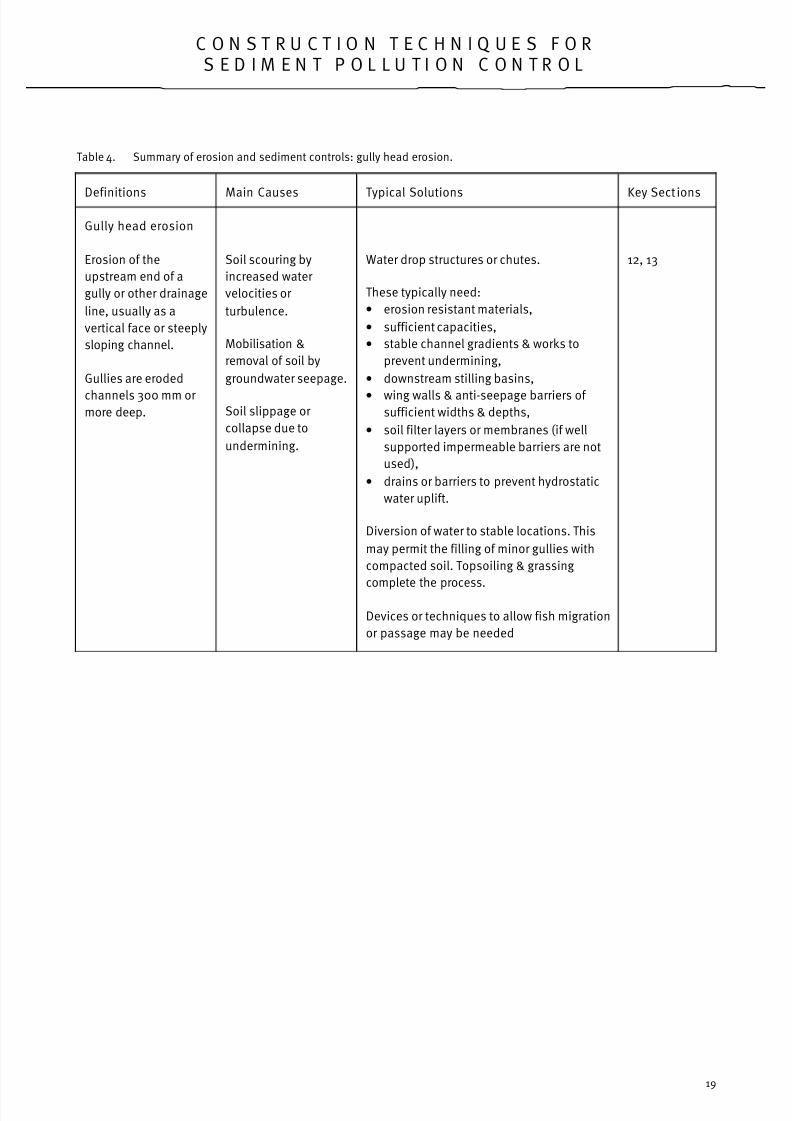
Table 4. Summary of erosion and sediment controls: gully head erosion.
Definitions Main Causes Typical Solutions Key Sect ions
Gully head erosion
Erosion of the
upstream end of a
gully or other drainage
line, usually as a
vertical face or steeply
sloping channel.
Gullies are eroded
channels 300 mm or more deep.
Soil scouring by
increased water
velocities or
turbulence.
Mobilisation &
removal of soil by
groundwater seepage.
Soil slippage or
collapse due to
undermining.
Water drop structures or chutes.
These typically need:
• erosion resistant materials,
• sufficient capacities,
• stable channel gradients & works to
prevent undermining,
• downstream stilling basins,
• wing walls & anti-seepage barriers of sufficient widths & depths,
• soil filter layers or membranes (if well
supported impermeable barriers are not
used),
• drains or barriers to prevent hydrostatic
water uplift.
Diversion of water to stable locations. This
may permit the filling of minor gullies with
compacted soil. Topsoiling & grassing
complete the process.
Devices or techniques to allow fish migration
or passage may be needed
12, 13
8/7/2019 EPA275 Sediment Control
http://slidepdf.com/reader/full/epa275-sediment-control 23/57
C O N S T R U C T I O N T E C H N I Q U E S F O RS E D I M E N T P O L L U T I O N C O N T R O L
20
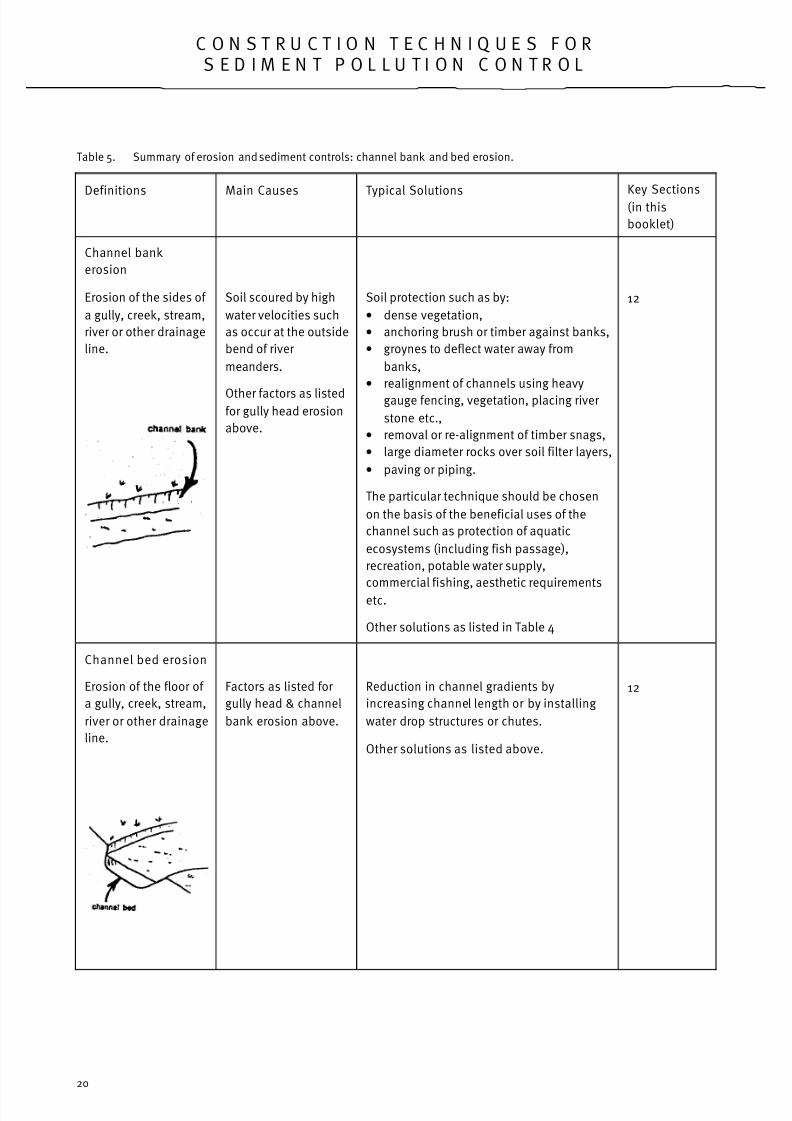
Table 5. Summary of erosion and sediment controls: channel bank and bed erosion.
Definitions Main Causes Typical SolutionsKey Sections
(in this
booklet)
Channel bank
erosion
Erosion of the sides of
a gully, creek, stream,
river or other drainage
line.
Soil scoured by high
water velocities such
as occur at the outside
bend of river
meanders.
Other factors as listedfor gully head erosion
above.
Soil protection such as by:
• dense vegetation,
• anchoring brush or timber against banks,
• groynes to deflect water away from
banks,
• realignment of channels using heavy
gauge fencing, vegetation, placing river
stone etc.,
• removal or re-alignment of timber snags,
• large diameter rocks over soil filter layers,
• paving or piping.
The particular technique should be chosen
on the basis of the beneficial uses of the
channel such as protection of aquatic
ecosystems (including fish passage),
recreation, potable water supply,
commercial fishing, aesthetic requirementsetc.
Other solutions as listed in Table 4
12
Channel bed erosion
Erosion of the floor of
a gully, creek, stream,
river or other drainage
line.
Factors as listed for
gully head & channel
bank erosion above.
Reduction in channel gradients by
increasing channel length or by installing
water drop structures or chutes.
Other solutions as listed above.
12

8/7/2019 EPA275 Sediment Control
http://slidepdf.com/reader/full/epa275-sediment-control 24/57
C O N S T R U C T I O N T E C H N I Q U E S F O RS E D I M E N T P O L L U T I O N C O N T R O L
21
Figure 12. Typical drainage works to minimise soil erosion and sediment pollution.
(f) Subsurface drainage
Subsurface drainage systems include gravel filled
(dutch) drains, slotted or perforated pipes along
gravel filled trenches and thick filter membrane
materials. Subsurface drains can greatly increase the
stabilities of steep batters. Site wetness problems
can also be reduced by subsurface drains.
Drains may also be needed to intercept
contaminated water seeping from storage dams and
other sources for diversion or pumping to secure
facilities (see also Sections 14 and 18).
(g) Water diversion
It is important to divert water along stable diversion
drains or banks around or away from exposed areas
of soil or loose material. This is often one of the
easiest and cheapest ways of preventing erosion and
sediment runoff.
Works along streams often require water to be
diverted around the work site. Such diversions are
often excavated as vertical trenches. If these are
excavated into highly erodible soils or are to remainfor more than about thirty days, they should be
protected by temporary membranes or other works
listed in sections (i) to (k) below.
(h) Construction of earthen diversion banks.
Earthen diversion banks can be used to intercept and
divert water away from erosion prone sites to stable
locations.
Earthen diversion banks can be constructed by
pushing soil downhill into a long mound
(a “cut and fill” diversion bank) or by pushing soil
uphill (an “all fill” diversion bank).
To avoid diversion bank channels becoming eroded,
they need to be surveyed at gradients no steeper
than about 05%, unless they are stabilized prior to
the occurrence of rainstorms (see pages 181 to 220 of
reference 22).

8/7/2019 EPA275 Sediment Control
http://slidepdf.com/reader/full/epa275-sediment-control 25/57

8/7/2019 EPA275 Sediment Control
http://slidepdf.com/reader/full/epa275-sediment-control 26/57
C O N S T R U C T I O N T E C H N I Q U E S F O RS E D I M E N T P O L L U T I O N C O N T R O L
23
Figure 14. Stream banks stabilized by dense native vegetation.
Drains should have broad flat “spoon” shaped floors
with sides no steeper than 2:1 (horizontal:vertical),
rather than narrow “V” shapes, to minimise water
velocities and erosion risk.
Grass downstream from eroded areas can be killed
by the long term abrading and smothering effect of
sediment. In such cases, the eroded areas should be
stabilized Otherwise structural erosion and sedimentcontrols will be needed along the drains.
ii) Mulch matting
To protect grass seed and topsoil applied along
minor or intermittent drainage lines, use a cover such
as dense sugar cane fibre matting covered with a
protective plastic mesh, entrenched and pinned
down (reference 21). Thickly woven jute mesh might
also be used in such locations (reference 32).
Light duty mulch, such as straw or wood fibres held
under mesh, is seldom effective along drainage lines
because soil particles, grass seed and fertilisers are
easily washed from below and through gaps within
such materials
iii ) Other plants
Appropriate species of sedges, cane grass, shrubs
and trees with deep fibrous roots may be suitable for
the stabilization of stream banks and waterlogged
locations. Such plants are often combined with and
are longer lasting than many structural stream
stabilization works.
iv) Fences:
Fences along streamside and other buffer zones are
needed to prevent damage to stabilizing vegetation
by livestock, vehicles or people. Warning signs may
also help in come cases

8/7/2019 EPA275 Sediment Control
http://slidepdf.com/reader/full/epa275-sediment-control 27/57
C O N S T R U C T I O N T E C H N I Q U E S F O RS E D I M E N T P O L L U T I O N C O N T R O L
24
v) Rock armouring
A surface armouring or beaching of rocks can beused to protect channel beds and banks from
erosion. However, the rocks need to be large enough
to resist dislodgement by peak water flows
(references 22, 24 and 40). Otherwise heavy gauge
steel mesh may be need to be placed over the rocks
to prevent them being dislodged by flood waters.
The most economic and environmental approach
along channel banks may be to install rock to a
height no more than that required to prevent bank
erosion. Dense vegetation could then be used to
stabilise higher portions of the bank.
A soil filter underlay is needed to prevent the rocks
from being undermined. Soil filter underlays typically
consist of crushed rock with average diameters of
about 60mm or synthetic geotextile filter
membranes. Small diameter rocks may not be
needed to filter soil if the surface layer of rocks is
thick enough and precautions are made to prevent
tunnel erosion in erodible soils (reference 22).
Figure 15. Thick layer of rocks with a large size range
It should be born in mind that geotextile filter
membranes tend to prevent the growth of plants.
This may be an advantage where uninterrupted water
flows are required but a disadvantage along stream
banks where it is desired to promote the growth of
vegetation. Topsoil interspersed amongst rocks can
assist in establishing vegetation.
Figure 16. A few large rocks by themselves are seldom
adequate to prevent side scour.
Rocks need to be shaped to form a channel large
enough to prevent side scour by storm waters.
Crushed rocks should be compacted to form an
erosion resistant pavement.
It is worth noting that crushed rock along roadside
drains in residential areas can help improve the
quality of runoff water in addition to controlling
erosion. Rocks should be thick enough for water to
trickle through the lowest layers where microbes help
break down pollutants. The base of such drains
should be evenly graded to prevent water ponding
and becoming stagnant.

8/7/2019 EPA275 Sediment Control
http://slidepdf.com/reader/full/epa275-sediment-control 28/57
C O N S T R U C T I O N T E C H N I Q U E S F O RS E D I M E N T P O L L U T I O N C O N T R O L
25
vi) Gabions
Rock in steel mesh gabions or mattresses aresometimes used to protect stream banks. Soil filter
underlays and seepage barriers are needed to
prevent undermining of such gabions or mattresses.
Other comments in the above section on rock
armouring are also applicable.
viii) Pipes:
Subsurface stormwater or trickle flow pipes may be
needed below or beside densely vegetated channels
to prevent vegetation damage. This may beparticularly needed where stormwater runoff rates
are increased by the hard paving of urban areas.
Stormwater pipes with safety grills may also be
needed for public safety reasons.
When installing pipes, use the correct pipe class and
connection types for the water pressures and in-
service stresses involved.
Where temporary protection of minor drains is
needed, it may be possible to butt pipes end-on-endprior to final positioning. Flexible pipes can
sometimes be used for temporary drainage in steep
locations.
Anti-seepage collars may be needed around pipes
where there is a risk of side scour or tunnel erosion
along the pipelines. Headwalls and inlet structures
are usually needed to direct water into pipes and
prevent water flowing down and eroding soil
alongside the pipes. Midstream alignment of pipe
outlets and energy dissipators may be needed to
prevent bed and bank erosion immediately
downstream.
Where water discharge rates are not high, it may be
possible to maintain or construct natural open
channels to preserve aesthetic and environmental
values. Other stabilization techniques listed in this
section may be needed for such channels.
Figure 17. Crushed rocks of about 60 millimetres diameter
need to be compacted into a rounded “spoondrain” shape.
viii ) Structures:
Water drop or chute structures can be used to reduce
channel gradients and water velocities.
Structures should be made to good engineering
standards from durable materials such as pipes, rock
or concrete. Typical construction standards are listed
in Section 13.
ix) Soil stabilizers:
It is sometimes useful to reduce the erodibility of soil
with gypsum, lime or cement. After thoroughly mixing
these materials into soil, the soil should be
moistened and compacted to good engineering
standards. This is needed to prevent alkaline water
discharges.
x) Gully filling:
Eroded channels or gullies can sometimes be
stabilized by filling them with soil and diverting water
by dams or diversion banks away from fill material to

8/7/2019 EPA275 Sediment Control
http://slidepdf.com/reader/full/epa275-sediment-control 29/57
C O N S T R U C T I O N T E C H N I Q U E S F O RS E D I M E N T P O L L U T I O N C O N T R O L
26
stable locations. Soil used to fill gullies should be
compacted in thin layers and finally covered with
topsoil originally stripped from gully sides.
Construction standards equivalent to those needed for
dam construction, such as through compaction of soil
in thin moist layers, are needed where diversion banks
cross gullies to prevent tunnel erosion in fill material.
xi) Pavement
Channels can often be protected by pavement
materials such as compacted asphalt, reinforced
concrete with well sealed expansion gaps or interlocking blocks over a soil filter layer. Drainage
pipes or layers may be needed below pavements or
membranes to prevent hydrostatic uplift and
underlying material being weakened by accumulations
of water.
xii) Temporary stabilization
Some construction projects may require temporary
erosion controls along drains and streams while
construction works are in progress.
Exposed soil could be protected by temporary
membranes such as tarpaulins, geotextile filter cloths,
rubber sheeting or thick polythene.
The upstream edges of such membranes should be
well secured to prevent them being washed away
should unexpected flood flows occur. Membranes
could be held down by large stakes, deep edge
entrenchment or heavy material such as large rocks.
Sand or soil filled bags can sometimes be used for
surface armouring, barriers or cutoff walls if placed
close together. If soil is used to fill bags, it should
have a low clay content or be stabilized with a smallproportion of cement to prevent water turbidity
problems.
However, the risk of bags splitting and their difficulty
of removal can make other techniques more
applicable for large streams. Other works such as
carefully anchored logs may provide temporary
protection in some cases.
Figure 18. Steep river bank stabilised by a thick layer of rock near a roadway.

8/7/2019 EPA275 Sediment Control
http://slidepdf.com/reader/full/epa275-sediment-control 30/57
C O N S T R U C T I O N T E C H N I Q U E S F O RS E D I M E N T P O L L U T I O N C O N T R O L
27
It should be noted, however, that membranes or filter
material are needed under materials such as tree
branches and car tyres with open gaps to prevent
underlying soil being removed by water turbulence.
Temporary soil binding agents such as asphalt or
glues should not be used where there is a risk of
environmental pollution.
xiii) Other techniques:
Other stream stabilization techniques include:
• diversion of water to stable locations,
• groynes to deflect water from channel banks,• realignment using heavy gauge fences, rock
placement etc.,
• removal or alignment of timber snags,
• anchoring of timber or brush against banks.
Such methods are detailed in reference 7.
(j) Channel gradients
For most of the channel stabilization techniques
listed above, it is usually necessary to excavate
channel banks to gradients no steeper than 2:1
(horizontal:vertical). More gentle channel banks may
be needed where they are prone to slippage or
undercutting. Excavated material should be disposed
of in stable locations. Do not pollute drainage lines
or streams by pushing soil straight into the water.
To prevent the erosion of unpaved channel beds,
their longitudinal gradients need to be no steeper
than about 0.5%. To achieve stable gradients, it may
be necessary to re-align channels or install water
drop structures (see Section 13).
(k) Vehicle Crossings
Considerable erosion and sediment pollution
problems can result where vehicles and earthmoving
machinery cross streams. Stable crossings need to be
installed in such locations. Construction techniques
for stream crossings are listed in Section 17.
(l) Livestock & public access
If livestock are allowed access to streams for drinkingpurposes, they damage protective vegetation and stir
up mud in the water. Livestock manures also reduce
water qualities. Stable stock watering and crossing
points can sometimes be provided along streams.
To prevent water pollution, however, livestock should
be excluded from streams and drainage lines as
much as possible and provided with off-stream
drinking locations. This is particularly important in
Proclaimed Water Supply Catchments.
To ensure livestock and public safety, fences may be
needed alongside channels with steep sides or which
experience high water flow rates. (See Section 6).
Figure 19. River bank stabilized by cane grass.
Figure 20. Soil pushed directly into streams results inwater pollution. This can usually be avoided by
careful planning based on the techniques listedin this booklet.

8/7/2019 EPA275 Sediment Control
http://slidepdf.com/reader/full/epa275-sediment-control 31/57
C O N S T R U C T I O N T E C H N I Q U E S F O RS E D I M E N T P O L L U T I O N C O N T R O L
28
1 3 . W A T E R D R O P O R C H U T E
S T R U C T U R E S
Water drop or chute structures are needed to
prevent soil erosion and sediment pollution
wherever water flows from one level down a steep
incline to a lower level. Such drops in water level
may also be needed to provide stable stream
gradients between the structures.
Water drop and chute structures should typically be
built from materials Listed in the previous Section
12(i) “Channel stabilization”.
No matter whether the structures are large or small
they should be designed and constructed to good
engineering standards, such as:
(a) water discharge rate calculations, site survey,
subsurface investigations and soil tests to
good engineering standards;
(b) construction materials and stabilisation
techniques which ensure that the structure
functions effectively for its design life (seeGlossary);
Figure 21. Large water drop structure with deep seepagebarriers and wing walls.
Figure 22. Poorly designed structure which has beenundermined and side scoured
c) sufficient channel and outlet notch capacities
to prevent overtopping or side scour of the
structures by design stormwater flows
(references 2, 8, 22, 25 and 36);
(d) stable channel gradients or works to prevent
soil erosion immediately upstream and
downstream of the structures;
(e) designs and gradients to prevent long term
sediment accumulation and excessive loss of
water discharge capacity;
(f) midstream structure outlet alignments to
prevent erosion of streambanks immediately
downstream;
(g) stable downstream gradients (usually less
than about 0.5%) to prevent streambed
erosion and undermining of structures;
(h) correct water inlet and outlet levels to
prevent the initiation of rill or gully erosion;
(i) stilling basins and energy dissipators of
sufficient capacities and widths to prevent
soil erosion and undermining of the
structures;

8/7/2019 EPA275 Sediment Control
http://slidepdf.com/reader/full/epa275-sediment-control 32/57
C O N S T R U C T I O N T E C H N I Q U E S F O RS E D I M E N T P O L L U T I O N C O N T R O L
29
(j) wing walls, headwalls and anti-seepage
barriers extended to sufficient widths and
depths (usually greater than 0.6 metres) to
prevent overtopping and undermining or
tunnel erosion;
(k) soil filter underlay layers or membranes, if well
supported impermeable barriers are not used,
to resist undermining or tunnel erosion;
(l) underdrainage, buttressing or sloping of
barriers to resist hydrostatic water pressures;
(m) devices or designs to allow fish passage and
migration.
The use of rock chutes over soil filter layers has
increased in recent years. In some erodible soils,
however, vertical anti-seepage barriers, similar to the
core of a dam embankment, may be needed to
prevent undermining.
Figure 23. Stilling basin used to dissipate water energy. Figure 24 Soil erosion has undermined this pipe outlet
and contributes to sediment pollution.

8/7/2019 EPA275 Sediment Control
http://slidepdf.com/reader/full/epa275-sediment-control 33/57
C O N S T R U C T I O N T E C H N I Q U E S F O RS E D I M E N T P O L L U T I O N C O N T R O L
30
Figure 25. Pipe outlet protected from erosion by a thick
layer of rocks.
Figure 26. One of several rock chutes which enables fish
passage along a creek.
1 4 . D A M S & B A S I N S
Dams and basins are useful for trapping sediment,
treating water pollutants and controlling flood
discharge rates. They can also act as emergency
traps in the event of accidental spillages of
petroleum, che micals or other polluting substances.
In addition, dams and basins can provide an
aesthetically pleasing community resource.
In areas with existing residential development,however, it is often difficult to find a sufficiently large
site with adequate soil types and land gradients for a
sediment trap dam. In addition, the concerns of local
residents need to be considered, such as water
safety.
(a) Sediment trap dams and basins
Wherever feasible, install adequately sized,
constructed and stabilized sediment trap dams
downstream from areas of loose soil Such dams
should be constructed prior to the commencement of
project earthworks, particularly where soil is to
remain exposed for more than about six months.
Where possible, construct dams or basins either
singly or in combination, with both sediment
trapping and flood detention functions. Dams with a
flood detention function can reduce water velocities
and thereby economise on downstream erosion and
sediment control works. To maximise this effect,
flood detention dams should have multi-stage
outlets with small diameter outlets being placed at
low levels.
Base flow outlet pipes should not be placed at the
base of or upstream from sediment trap dams.
Installing outlets in such locations can result in large
quantities of sediment by-passing the dams or
basins.

8/7/2019 EPA275 Sediment Control
http://slidepdf.com/reader/full/epa275-sediment-control 34/57
C O N S T R U C T I O N T E C H N I Q U E S F O RS E D I M E N T P O L L U T I O N C O N T R O L
31
(b) Construction Standards
It is important to construct dams and basins to highstandards to ensure their long term stability,
effectiveness and safety. In Victoria inadequate soil
compaction, poor seepage controls, embankments
exposed to erosion and undersized spillways are
common problems (reference 31 and personal
communication, Nelson).
In the worst cases, embankments become tunnel
eroded or breached; in other cases, dams have a
greatly reduced life or require expensive
maintenance. The failure of a dam embankment can
result in significant sediment pollution in addition to
damaging downstream areas and being hazardous to
the public.
Figure 27. Sandy sediment trapped in a dam.
If a dam embankment is five metres or more high and
its capacity at least 50 megalitres, or the
embankment 10 metres or more high and its capacity
at least 20 megalitres, it needs to be referred to the
Office of Water Resources, Department of
Conservation and Environment (references 2 and 8).
It is recommended that dams with embankments
higher than about four metres or capacities greater
than about ten megalitres be designed and their
construction supervised by suitably qualified and
experienced civil engineers. This should also be the
case for dams built in hazardous or difficult
locations.
The requirements of the responsible drainage
authority should also be followed.
Additional information about dam design and
construction is contained in references 22, 31 and 34
and their bibliographies.
(c) Site Investigations
Thorough investigation of soil and site conditions is
important for adequate dam design and to avoid
costly design changes if unpredicted features, such
as permeable layers or hard rock are encountered.
A network of soil tests should be made at depths of
at least two thirds the dam embankment height and
deeper than the excavation depths.
Other investigations include contour surveys and
water discharge rate calculations.
Figure 28. Dam embankment which has been breached by
water as a result of poor soil compaction.
8/7/2019 EPA275 Sediment Control
http://slidepdf.com/reader/full/epa275-sediment-control 35/57
C O N S T R U C T I O N T E C H N I Q U E S F O RS E D I M E N T P O L L U T I O N C O N T R O L
32
(d) Gradients
Construct dams or basins on land no steeper than10% (10:1 horizontal vertical). Such locations are
needed to minimise hillside excavation and resultant
increased risks of landslip, soil erosion and sediment
discharge.
In addition, earthen dams are difficult to construct to
good engineering and safety standards on land
steeper than 10% gradient. Vertical sided tanks and
inlet chute structures may be better options in steep
locations.
(e) Capacities
Wherever possible, sediment trap dams should be
designed to trap the majority of sediment particles
suspended in discharge waters.
The capacities of sediment trap dams can be
calculated in different ways depending on factors
such as water quality objectives, water discharge
rates and settlement rates of suspended materials.
One or more of the following criteria could be chosen
on the basis of information contained in the
references at the end of this document. Capacities
should be increased to allow for sediment
accumulation and removal rates.
i) Recurrence interval
Construct sediment trap dams to retain the discharge
of all average five year recurrence interval storms.
This provides for the retention of runoff from heavy
rainstorms.
ii) Yearly runoff
Construct sediment trap dams with capacities
equivalent to average yearly rainfall runoff events
(typically about 150 cubic metres per hectare). This
provides for the retention of average runoff rather
than heavy rainfall events.
iii) Silt retention
Construct sediment trap dams with minimum water storage areas of 4,000 square metres for every cubic
metre per second of design maximum peak water
flow. This usually results in retention of most silt and
larger sized particles (0.02mm diameter Such
particles are also trapped if the dam is designed to
provide a one hour retention period for average five
year recurrence interval stormwater flows.
iv) Clay retention
Most clay sized particles (less than 0.002 mmdiameter), tend to be retained if the dam has a 10
hour retention period for average five year recurrence
interval stormwater flows. This may require a dam of
very large capacity. Some types of dispersible clay
tend to remain in suspension for periods longer than
10 hours unless treated with a flocculant (Section
14).
v) Erosion rate.
Construct sediment trap dams with sufficientcapacities to trap sediment calculated to result from
average yearly erosion rates (references 22 and 24).
This allows for the retention of a significant
proportion of material eroded each year.
vi) Long term control
Access tracks to dams in steep terrain may
themselves pose significant erosion and sediment
pollution risks. In these situations, it may be
desirable to avoid the construction of access tracks
and build larger dams.
(f) Inlet baffles
Inlet baffles and islands can be used to spread
sediment within water storage areas and maximise
the volume of sediment trapped.
(g) Water depths
Construct the water storage areas of sediment trap
dams with minimum water storage depths greater

8/7/2019 EPA275 Sediment Control
http://slidepdf.com/reader/full/epa275-sediment-control 36/57
C O N S T R U C T I O N T E C H N I Q U E S F O RS E D I M E N T P O L L U T I O N C O N T R O L
33
than 60 centimetres plus an allowance for sediment
deposition. This is needed to help minimise
sediment re-suspension.
If a dam is completed during a dry season, it may be
desirable to fill it with enough water to keep the
embankment moist and free from shrinkage cracks.
Drying and cracking of a dam embankment can result
in its failure when the dam is eventually filled with
water (reference 31).
(h) Embankment sides (batters)
Sufficient widths need to be provided at the site for
stable dam embankment and excavation gradients.
Cross sectional drawings at appropriate scales can
assist in this task.
High embankments may need horizontal berms and
downstream toe drainage to increase their stability.
Toe drains should be made from carefully graded and
installed filter materials to prevent tunnel erosion.
Additional information is provided in references 22,
31 and their bibliographies.
(i) Core trench & embankment foundation
It is important to remove all topsoil from below
proposed dam embankment areas to provide for
embankment stability and leakage control.
Excavate a core trench below the centre or the
upstream portion of the embankment and at least
0.6 metres into impervious rock or solid clayey
subsoil (references 22 and 31).
Surface scarify exposed subsoil clay to a depth of nomore than 20mm to assist in embankment bonding.
Water may leak through more deeply ripped layers.
These works are important if the embankment is
higher than 1.5 metres, the site steeper than 5%
gradient or wherever needed to prevent water
seepage or improve dam safety. On the other hand,
small dams in safe gently sloping locations could be
designed to leak to assist in sediment trapping and
de-watering.
(j) Soil type & compaction
Clayey soils with suitable engineering characteristicsmust be used for earthen dam embankments.
Compact clayey embankment material in thin layers
when moist according to standard engineering
compaction tests and techniques. (See references
23, 31 and 38). This usually involves compaction of
soil at optimum moisture contents when it is pliable
or plastic, with a heavy sheepsfoot or padfoot roller.
The use of bulldozer tracks or rubber tyres alone to
compact the soil is not recommended because they
exert a low pressure on the ground and are relatively
inefficient at compacting soils. Their use tends to
result in horizontal layers of permeable soil which are
prone to tunnel erosion and excess seepage and can
result in structural failure of the embankment.
Vibrating rollers can also cause horizontal layering in
some cases.
Soil moisture contents and compaction densities
should be assessed according to Australian
Standards (reference 38). If the soil is not sufficientlymoist, deep ripping and pre-irrigation may be
needed. Additional water may need to be applied
during hot weather to prevent the soil becoming too
dry while it is being compacted.
Adequate soil compaction and sub-base preparation
are important to prevent settlement cracks and other
damage in day or membrane linings in dams.
(k) Soil treatment
Gypsum, slaked lime or cement may need to be
incorporated into embankment and basin material
where needed to reduce soil dispersibility, water
turbidity or the risk of tunnel erosion. Soil tests can
help to estimate the application rates needed. If soils
are highly credible or permeable, the advice of a civil
engineer with experience in dam design and
construction should be obtained.

8/7/2019 EPA275 Sediment Control
http://slidepdf.com/reader/full/epa275-sediment-control 37/57
C O N S T R U C T I O N T E C H N I Q U E S F O RS E D I M E N T P O L L U T I O N C O N T R O L
34
(l) Embankment crests
Crowning or side-sloping of embankment crests isneeded to prevent water ponding on the crest and
causing tunnel erosion within the embankment.
(m) Embankment surfaces
Exposed soil on dam embankments needs to be
stabilised with dense grass growing in 50mm to
70mm of loamy topsoil unless stabilised by rock
armouring over a soil filter underlay. Thicker layers of
topsoil tend to slip off steep batters.
If embankments are composed of highly expansive
(cracking) clay soils, spread a thick layer of surface
stabilised sandy material to help minimise soil drying
and cracking. This is needed to prevent embankments
slipping or becoming tunnel eroded where water flows
along shrinkage cracks (reference 31).
(n) Wave protection
Protect embankments from wave damage where this
is likely to be excessive, by providing rock armouring
or similar material over soil filter underlays. Aquatic
plants such as cane grass can also prevent wave
erosion. Floating breakwaters or booms may reduce
wave erosion where wave heights are not high.
Surface protection is particularly important for clay
linings in dams.
(o) Outlet structures & freeboard
Sufficient outlet capacities and Freeboard should be
provided to prevent water overtopping dam or basinembankments or structures during flood water flows.
Freeboard should include an allowance for wave
action and extreme flood events (references 2, 8, 22
and 31). Several different types or combinations of
outlet structures are possible for sediment trap
dams. The particular design should be based on
information contained in the previous Section about
structures and references 2, 8, and 31.
If a sediment trap dam is also used for flood
detention, the following designs are needed:
i) Ricer pipes
Install perforated or slotted riser pipes surrounded by
small diameter crushed rock or equivalent filter
material to allow gradual water discharge from
sediment trap dams and basins;
OR
ii) Flexible pipes
Attach flexible outlet pipes to floats to allow gradualwater discharge from sediment trap dams and
basins;
AND/OR
Extra freeboard
Provide sufficient freeboard between the outlet pipe
and the dam bywash or spillway for the dam to have
adequate flood detention and sediment trapping
capacities.
(p) Pipe tests
Undertake pipe pressure tests both before and after
pipe trenches are filled with compacted soil to
ensure that outlet pipes have not cracked and do not
leak or fail.
(q) Pipe collars
Install anti-seepage cutoff collars of sufficient widths
and at sufficient spacings along outlet pipes toprevent tunnel erosion along the pipe trenches
(references 22 and 31).
Ensure that soil is well compacted in thin layers when
moist by manual techniques along pipe trenches.
Manual compaction is usually needed to protect the
pipe from damage which can result from mechanical
techniques.

8/7/2019 EPA275 Sediment Control
http://slidepdf.com/reader/full/epa275-sediment-control 38/57
C O N S T R U C T I O N T E C H N I Q U E S F O RS E D I M E N T P O L L U T I O N C O N T R O L
35
Figure 29. Cross sections of typical sediment trap and flood detention dams.
(r) Water hammer
Water hammer effects which can damage pipes and
connections can result from the closing of valves, air
entrapments and variations in water velocities.
Broken or leaking pipes can result in soil erosion and
contribute to sediment pollution.
Such problems can be avoided by installing air inlet
pipes, curved pipe connections, pressure relief
valves, water riser pipes and surcharge wells.
(s) Spillways
Erosion of dam spillways and bywashes can be
avoided by installing works such as trickle water flow
pipes, water drop or chute structures, or by
undertaking other appropriate channel stabilization
works (Sections 12 and 13).

8/7/2019 EPA275 Sediment Control
http://slidepdf.com/reader/full/epa275-sediment-control 39/57
C O N S T R U C T I O N T E C H N I Q U E S F O RS E D I M E N T P O L L U T I O N C O N T R O L
36
(u) Control livestock
Prevent the access of livestock to dams or basinssuch as by installing stock proof fencing. This is
needed to prevent the livestock muddying and
fouling the water and trampling protective
vegetation. Offstream stock water troughs are often a
better alternative.
(v) Minor sediment traps
A small sediment trap dam or structure installed
upstream from the main sediment trap dam can be
useful for reducing the difficulty and cost of trappingand removing sediment (see also Section 15).
(w) Maintenance
Dams and basins should be regularly checked and
repaired as needed.
Sediment needs to be removed from sediment trap
dams, basins and structures at sufficient frequencies
to maintain storage capacities and to ensure their
ongoing effective operation. It may be desirable to
specify a maximum depth of sediment deposition,
typically no more than one third of total storage
depth, before which sediment is to be removed.
Excavated sediment should be deposited in stable
locations and its surface stabilised.
It should be noted that mosquitoes can be controlled
by stocking dams with predatory fish. It follows that
control of sediment and related pollutants is needed
to help protect such fish (references 4 and 16).
Isolated pools of water without fish access may need
to be removed to prevent the breeding of
mosquitoes. Such considerations are needed to
foster public support for sediment trap facilities.
(x) Leachate control
Dams are sometimes used to store leachate or
contaminated water from mines, tips etc. To ensure
that such leachate does not seep too far from a dam,
it may be necessary to install monitoring bores, spear
wells, intercept drains or additional dams near the
main storage dam.
Dams and basins need to be constructed and
maintained to high standards to ensure their long term
stability, effectiveness and safety. Works such as
fences, warning signs and buffer zones may be
needed to ensure the safety of dams and basins to the
public and to livestock.
1 5 . S E D I M E N T & L I T T E R T R A P S
Where there is insufficient space for sediment trap
dams or basins, smaller sediment trap structures maybe possible.
Sediment trap structures are often not large enough to
trap more than a fraction of the sediment discharged
from land disturbance sites. In such cases, it may be
necessary to increase the number of sediment traps
and decrease the catchment area to each trap.
Litter is a major pollutant of urban waterways and can
often be controlled by the use of litter screens and
floating booms combined with sediment traps or
dams. Litter traps may also be needed to prevent
drains becoming blocked if sediment trap materials
such as hay bales fail and are washed downstream.
(a) Location
Sediment and litter traps should be installed at
strategic locations such as premise boundaries or
culvert pipe inlets and wherever needed to minimise
the risks of downstream sediment and litter pollution.
Litter and sediment traps are sometimes combined as
gross pollution traps just upstream from lakes and
wetlands (references 36, 37 and 39).
(b) Sediment trap materials
Sediment traps can be constructed from materials
such as steel drums, gravel filled bags, cement
stabilized sand bags, staked and entrenched hay
bales, boards, concrete basins, earthen
embankments, stones held under geotextiles, crushed

8/7/2019 EPA275 Sediment Control
http://slidepdf.com/reader/full/epa275-sediment-control 40/57
C O N S T R U C T I O N T E C H N I Q U E S F O RS E D I M E N T P O L L U T I O N C O N T R O L
37
rock, filter cloth fences, filter bags suspended on
steel frames or filter membranes over steel drums
(references 22, 24, 30, 36 and 37).
Heavy duty materials, such as closely spaced steel
pylons with heavy gauge steel mesh supporting filter
cloth membranes may be needed where high water
flow rates are involved.
(c) Earthen embankment sediment traps
Earthen embankments or bunds can be used to both
divert water and trap sediment. They should be built
from soil compacted in thin layers when moist.Earthen embankments and their channels usually
need to be stabilized with dense grass or a covering
such as heavy duty edge entrenched geotextiles,
membranes or mats.
(d) Sediment trenches & pits
Trenches and pits may be adequate to trap sediment
where catchments and water flow rates are small,
such as for individual house construction sites.
Where soils are erodible and the land is steeper thanabout 3% gradient or the catchment greater than
about 0.5 hectares, the trenches and pits usually
need to be stabilized to prevent them being eroded
and contributing to further sediment discharge.
e) Sediment trap design
To ensure their effectiveness, sediment traps,
whether la rge or small, need to be designed
according to the same principles listed for other
hydraulic structures in Sections 13 and 14.
They should, for example, have erosion resistant
spillways and storage areas to maximise the volumes
of sediment trapped. Sediment trap fences such ashay bales and filter cloth membranes often need to
be entrenched to resist undermining (reference 32
and 37).
Entrenched barriers such as metal sheets or piles
may be needed to reinforce sediment traps,
particularly where high water flow rates or erodible
soils are involved. These should be driven into both
the channel sides and the channel floor.
Entrenchment depths typically need to be greater
than 600 mm.
Figure 30 Sediment trap featuring litter screens to prevent pipe blockage and concrete and plastic aprons to prevent
undercutting.

8/7/2019 EPA275 Sediment Control
http://slidepdf.com/reader/full/epa275-sediment-control 41/57
C O N S T R U C T I O N T E C H N I Q U E S F O RS E D I M E N T P O L L U T I O N C O N T R O L
38
Sediment traps should be designed to allow easy
sediment removal. The use of front end loaders to
remove sediment, for example, may be possible if
the sediment traps have sloping sides. This can be
particularly useful for permanent concrete sediment
trap structures.
Upstream “clean water” overflow outlets may be
useful if water in sediment traps is pumped out or
discharged on an ongoing basis. Grossly polluted
water in such locations should be discharged as
appropriate to land, sewer or mobile tankers for
waste treatment.
(f) Gradients
Sediment traps by themselves are seldom effective
along eroding drainage lines with gradients steeper
than about 2%. Channel and catchment
stabilizations works are needed as well.
(g) Capacities
Where sufficient space is available, sediment trap
capacities should be designed according to the samecriteria for dams and basins in Section 14(e) above.
(h) Stabilization of sediment traps
Materials used for sediment traps need to be
sufficiently stable to resist peak water flows.
Stakes, geotextile covers, steel mesh and other such
materials can be used to prevent sediment trap
structures breaking up and causing litter problems
and obstructions downstream. Litter screens located
at or downstream from sediment traps can serve the
same purpose.
Figure 31. This hay bale sediment trap has not been
effective because the channel is steep andunstabilized. This has resulted in erosion along
the channel and around the sides of the bales.
Figure 32. Sediment trap with a sloping concrete ramp to enable easy sediment removal.

8/7/2019 EPA275 Sediment Control
http://slidepdf.com/reader/full/epa275-sediment-control 42/57
C O N S T R U C T I O N T E C H N I Q U E S F O RS E D I M E N T P O L L U T I O N C O N T R O L
39
Figure 33. Row of entrenched hay bales which traps sediment and diverts muddy water into densely grassed areas.
Crushed rock, entrenched membranes or other
materials can be used to prevent undermining of
structures or side scour.
Wherever possible, connect sediment trap structures
in-line with gently sloping diversion banks. This will
result in near level inlets and outlets and can help
prevent the structures being undermined by stormwaters.
(i) Litter screens & booms
Litter screens and floating booms are sometimes
combined with sediment traps. Litter screens can be
built from closely spaced steel bars, steel mesh
supported on steel posts or other similar materials.
They are typically located at culvert inlets, sediment
trap dams or basins, and where drainage lines leave
premise boundaries.
Litter screens made from steel bars can double as
safety grids to prevent access by children and others
to pipelines and drainage systems.
The size of openings in litter screens needs to be
designed on the basis of the type of litter to be
collected. Openings may need to be smaller than soft
drink cans, for example. It may not be desirable,however, to use small circular openings which trap
grass and leaves which may block the screen.
A stable emergency bywash around or over each litter
screen is needed to prevent flooding problems
should the litter screen become rapidly blocked with
debris.
Litter screens should be constructed from heavy duty
materials where high water velocities or depths are
involved. Litter can be washed over the top of litter

8/7/2019 EPA275 Sediment Control
http://slidepdf.com/reader/full/epa275-sediment-control 43/57
C O N S T R U C T I O N T E C H N I Q U E S F O RS E D I M E N T P O L L U T I O N C O N T R O L
40
screens during high stormwater flow events.
To reduce this problem, litter screens with discharge
capacities equivalent to at least one year average
recurrence interval storm discharges and preferably
more than five year intervals are recommended.
Floating litter booms can also trap floating litter
which would otherwise flow over the top of the
screens.
However, floating booms may require more frequent
repair than heavy duty litter screens.
Figure 34. Filter cloth sediment trap fence used to trapsediment from a small catchment.
(j) Maintenance
Regular repair and maintenance of sediment trapstructures and litter screens, such as removal of
trapped material after rainstorms, is needed to
ensure their ongoing effectiveness. Removal of
material when sediment traps are up to one third full
may need to be specified in works programs to
achieve this.
Figure 35 Sloping debri screen which allows easy debris
removal. A floating boom upstream from theemergency spillway could be used in urban
areas to trap additional litter

8/7/2019 EPA275 Sediment Control
http://slidepdf.com/reader/full/epa275-sediment-control 44/57
C O N S T R U C T I O N T E C H N I Q U E S F O RS E D I M E N T P O L L U T I O N C O N T R O L
41
.
Figure 36. Floating litter boom in a sediment trap dam.
1 6 . W A T E R T R E A T M E N T
Muddy water trapped in dams, basins, trenches and
sediment traps may need to be treated prior to
discharge to meet State Environment Protection
Policy water quality objectives (reference 44).
(a) Pumping out
Adequate qualities of pumped water can often be
achieved by simply pumping from just below the
water surface after suspended matter has been
allowed enough time to settle. To help achieve this,
flexible pipe inlets to pumps could be suspended on
floats.
Pump inlet pipes should not be simply dropped onto
the base of trenches where they can suck mud.
Surrounding pump inlets with filter material such as
coarse gravel or locating them over a membrane,
baffle or board may also prevent the sucking of mud.
The use of screens on pump inlets which are located
just below the water surface can minimise the risk of
floating litter blocking the pump or being discharged.
(b) Flocculation
Wherever needed, clarify water in trenches or basins
prior to pumping them out by the use of a minimum
quantity of flocculent. Depending on water tests, fine
grained gypsum (calcium sulphate) should be used
as a flocculant in preference to filter alum (aluminium
sulphate). Filter alum requires water pH to be
adjusted using slaked lime (calcium hydroxide).
A water pH at or close to neutral (pH 7) should be
achieved. (See Glossary and Section 2b).
Water tests should be undertaken prior to water
treatment to assess the effectiveness of treatmentand to calculate the minimum rates of chemical
flocculants needed.
Flocculants can be useful as both a pre-dose by
mixing them with soil in trenches or basins to be
filled with water, and as a final dose before pumping
water out. It may be possible to add flocculants with
automatic dispensers at basin inlets. Otherwise, the
use of pumps or propellers to mix the flocculent in
the water may be needed.

8/7/2019 EPA275 Sediment Control
http://slidepdf.com/reader/full/epa275-sediment-control 45/57
C O N S T R U C T I O N T E C H N I Q U E S F O RS E D I M E N T P O L L U T I O N C O N T R O L
42
Dragging a hessian bag full of flocculant through the
water is another technique for spreading flocculant.
(c) Settling areas
If muddy water is not clarified prior to being pumped
from trenches or basins, it should be pumped into
broad hollows or densely vegetated areas to allow
sediment to settle out. Alternatively, sediment trap
dams or filters may be possible.
(d) Filters
In steep locations, it may be necessary to filter
muddy water by one of the following devices.
It should be borne in mind that large quantities of
sediment may need to be removed at regular
intervals from such devices.
i) woven plastic filter bags on steel frames (such
as used for waste paper),
ii) geotextile filter membranes suspended in or
over steel drums or portable tubs,
iii) gravel or crushed rock bunds, covered with a
filter cloth,
iv) well secured screens or permeable foam
rubber plugs at the entrance of stormwater
inlets (where flooding is not a problem if the
filters become blocked),
v) reverse flush industria l filters or cyclone
centrifuges.
Figure 37. Woven plastic woolbale bags held on a steelframe can be useful for trapping sediment.
1 7 . V E H I C L E S & R O A D S
Eroding access tracks and areas disturbed byconstruction equipment are often a significant source
of sediment pollution and wind blown dust. These
problems often remain after construction activities
have finished wherever roadside drains are not
stabilized and adjacent areas are not revegetated.
It is particularly important to stabilize steep roads
and drains from which muddy water flows directly
into creeks and streams.
(a) Road and track stabilization
All road and track surfaces and side drains should be
stabilized to minimise soil erosion and sediment
discharge.
If gravel roads or tracks are involved, erosion and
sediment discharges can be reduced by maintaining
a well crowned or side sloped surface. This is often
needed to prevent water flowing down and eroding
tyre track depressions. Maintaining a hard surface of
compact gravel can also reduce erosion andsediment discharge rates (reference 23).
An alternative approach is to provide frequent
surface cross drains or roll-over bunds to minimise
the distance that water flows along the road or track
surfaces (references 22, 23 and 32).
Water runoff from gravel roads and tracks should be
diverted into broad vegetated areas or sediment trap
dams, structures or basins prior to its discharge into
streams, rivers or other surface waters.
Roadside tabledrains should preferably be stabilized
with dense grass to prevent erosion and to help trap
water borne pollutants. Alternatively, crushed rock
could be used to stabilise roadsides as shown in
figure 17.
Even paved roadside tabledrains are better than no
stabilization at all. Subsurface drainage works are
often needed below paved tabledrains however, to
prevent road surfaces becoming damaged and

8/7/2019 EPA275 Sediment Control
http://slidepdf.com/reader/full/epa275-sediment-control 46/57
C O N S T R U C T I O N T E C H N I Q U E S F O RS E D I M E N T P O L L U T I O N C O N T R O L
43
potholed by accumulated water. This is important for
the provision of erosion and sediment control in the
long term.
Where roadside tabledrains are not stabilized,
frequent tabledrain outlets which divert water into
stable locations are needed to minimise erosion and
sediment discharge.
In some locations with low traffic densities, it may be
possible to stabilize roadside shoulders with grass.
Otherwise, paving road shoulders with asphalt or
concrete may prevent erosion of shoulder material.
This can greatly reduce maintenance costs and
improve road safety.
Figure 38. Roadside tabledrain stabilized with grass.
(b) Restrict access
On construction sites, vehicles should be restricted
to a minimum number of paved or stabilized access
tracks and haul roads to minimise the area of soil
disturbance and corresponding erosion and
sediment discharge rates.
(c) Intercept Culverts
Muddy water can be prevented from flowing downtracks and out of premises by installing metal grid
covered box culverts across the tracks and leading to
sediment traps. Culvert sizes and designs should be
used which allow easy sediment removal.
(d) Stream crossings
Use culvert pipes, rock pavements, logs or bridges to
prevent the disturbance of streams and other
drainage lines at vehicle crossing locations.
Soil erosion at such locations should be preventedby techniques outlined in Sections 12 and 13.
Soil erosion around culvert pipes may need to be
prevented by installing vertical concrete headwalls or
surrounding the pipes with geotextile filter cloths or
soil filter material.
Bridges may be a feasible alternative to pipes and
any other techniques which cause excessive
disturbance of stream beds and banks. Works to
prevent erosion undermining bridges may be needed
at the outside bends of streams or where the channel
is narrow and constricts water flow.
(e) Dirt on roads
Urban runoff is a major pollutant of many rivers and
streams (reference 1). It is therefore important to
remove soil and other loose material dropped,
washed or blown onto roads at the earliest available
times. This is needed because soil on hard
pavements becomes readily mobilised by wind or
rainwater runoff.
Techniques to remove soil and other loose material
should be used which themselves minimise water
runoff and the generation of air-borne dust. Simply
hosing down streets and roads can generate large
quantities of polluted water in addition to creating a
slippery surface which can become a traffic hazard.
Physical or manual removal of loose soil should be
the first approach in all situations.

8/7/2019 EPA275 Sediment Control
http://slidepdf.com/reader/full/epa275-sediment-control 47/57
C O N S T R U C T I O N T E C H N I Q U E S F O RS E D I M E N T P O L L U T I O N C O N T R O L
44
Figure 39. Eroded roadside tabledrain which contributes to
sediment pollution.
(f) Minimise mud dropped on roads
Mud often becomes trapped between the dual
wheels of trucks if they are driven across wet clayey
sites. When mud or soil is dropped onto roads, it can
become a dust nuisance and is readily washed into
drains and streams. These problems can be reduced
by restricting the passage of trucks to paved or
stabilised roads and tracks wherever possible.
The quantity of mud deposited on roads can also bereduced by installing a recycled water vehicle
washing facility. Alternatively, structures such as
cattle grids or rows of railway sleepers can help trap
mud. Covering exit tracks with a pavement such as
compact crushed rock can also help to keep mud
within the project area. Occasional reworking and
compaction of crushed rock can help remove
accumulations of muddy soil.
It should be noted that long grids designed to
vigorously vibrate mud from truck tyres may not be
acceptable if they contribute to vehicle wear and
increase the risk of back injuries to truck drivers.
(g) Cleaning of vehicles and equipment
All vehicle washing facilities must comply with the
Environment Protection Act 1970 and relevant
regulations relating to vehicle wash facilities.
These regulations require an EPA licence for vehicle
wash facilities which are not used by the public for
the washing of motor vehicles (reference 52).
The following controls can help to prevent water
pollution resulting from the cleaning of vehicles andconstruction equipment.
Figure 40. Grid covered intercept culvert.
i) Recycling
Water can be polluted by soil, alkaline cement
products and other materials washed or dropped
from construction vehicles and equipment.
This problem can be reduced by the use of a recycled
water washing facility at the project site. Recycling

8/7/2019 EPA275 Sediment Control
http://slidepdf.com/reader/full/epa275-sediment-control 48/57
C O N S T R U C T I O N T E C H N I Q U E S F O RS E D I M E N T P O L L U T I O N C O N T R O L
45
reduces the volume of water used, and assists in the
later disposal of wastewater to appropriate disposal
facilities.
ii) Waste minimisation
Wherever possible, brush or scrape soil and mud
from vehicles and equipment prior to washing. This is
needed to reduce the volumes of contaminated water
produced. The use of gently sloping concrete wash
bays can facilitate this process. Solid material should
be shovelled or scraped from wash bays rather than
hosed away.
To prevent wastewater discharges being increased by
rainfall, it may be possible to install a roof over the
facility. For both roofed and unroofed facilities,
rainfall runoff should be diverted elsewhere,
wherever possible, by diversion drains or bunds.
To further reduce the quantity of contaminated water,
it is often possible to install a system of valves or
pumps to separate rainfall discharges from wash
waters. These systems are usually operated by float
controls, water pressure sensors or water quality
sensing devices.
iii) Pumps
To pump water which becomes gritty or muddy in
vehicle wash facilities, centrifugal pumps are
needed. Two such pumps should be installed in case
one pump breaks down. The use of two pumps also
enables both sides of a vehicle to be washed at the
same time.
iv) Oil separation systems
To remove oil prior to wastewater recycling or
disposal, an oil settlement and separation system,
such as a gravity or parallel plate separator, can be
useful. This will reduce the difficulty of wastewater
disposal and the problem of spraying oily water onto
vehicles.
v) Detergents
Do not use any detergents (surfactants) at thewashing facility unless rainwaters are also prevented
from entering the facility. This is needed to prevent
the discharge of oils which can be emulsified by
surfactants. Emulsified oils are very difficult to
remove from wastewater.
vi) Concrete supply systems
Wash-out waters from concrete supply trucks and
pumping systems should be recycled or collected to
prevent alkaline discharges. This should occur evenif these are only partially cleared of concrete. Steel
drums, on-site sumps or other containers may be
needed to recycle such wastewater. Wastewater for
disposal should be transported to an appropriately
licenced disposal facility. Such wastes can be useful
to waste recycling companies to neutralise acidic
wastes (Section 18).
1 8 . M A I N T E N A N C E & W A S T E
D I S P O S A L
Some of the most important clauses in construction
specifications and conditions relate to maintenance
and waste control. Many works, such as sediment
traps, require frequent maintenance and waste
removal for them to operate effectively.
(a) Allocate personnel
All pollution control works should be maintained and
repaired to ensure their ongoing effectiveness.
To achieve this, it is desirable to provide a person or
group to specifically inspect sediment and other
pollution control works on a frequent basis,
particularly during installation and after rainstorms.
At these times, the operation of these works needs to
be assessed and their effectiveness improved
wherever possible.

8/7/2019 EPA275 Sediment Control
http://slidepdf.com/reader/full/epa275-sediment-control 49/57
C O N S T R U C T I O N T E C H N I Q U E S F O RS E D I M E N T P O L L U T I O N C O N T R O L
46
(b) Waste control
Many types of waste in addition to sediment arecommon at construction and other land disturbance
sites. Under the Environment Protection Act 1970,
waste includes any matter which is discarded,
emitted or deposited in the environment and which
can cause an alteration in the environment.
Typical contract specifications to help control waste
could include:
Prevent litter, floating material, paper articles, plastic
articles, drink cans, waste building products or anypolluting material being washed, blown or deposited
into streams or drainage lines from the premises;
and
Ensure that no litter, refuse, chemical, oil or other
polluting substance is left or buried at the premises
at project completion.
The filling of erosion gullies and stream banks with
loose waste materials such as fence wire, car bodies,
paint tins, corrugated iron sheets, tree branches andcar tyres, in an attempt to control erosion, is not
permitted by the Litter Act 1987 and the Environment
Protection Act 1970 (references 46 and 49). Water
flowing around such obstructions without adequate
soil filter membranes and seepage barriers, often
increases the rates of erosion.
Hollows in loose material provide a harbour for
vermin. If soil is pushed over loose waste, it often
becomes tunnel eroded and presents a safety hazard
to livestock and the public. In addition, the cost of
long term erosion control, which may require removal
of loose waste, is greatly increased.
(c) Spillages
Under the Environment Protection Act 1970 and the
State Environment Protection Policy (Waters of
Victoria) (references 44 and 46), it is essential to
contain and collect accidental spillages of oils, fuels
or chemicals and to prevent their discharge into
drainage systems. Such spillages can typically be
contained and collected by the use of earthen bunds,
dams, structures, sand bags, soil filled bags, floating
booms, suction tankers or the spreading of materials
such as sawdust, topsoil or absorbent granules.
Bunds or dams should be installed upstream from
environmentally sensitive areas where protection
from accidental spillages is deemed necessary.
Store pollution control equipment and materials,
such as fuel absorbent mats or granules, in areas
where there is a high pollution risk or environmental
sensitivity.
(d) Bunding
Surround containers used for on-site storage of fuels,
chemicals or similar materials with impermeable
bunds to provide a storage capacity equal to the
capacity of the largest tank plus 10% of the
remaining tanks plus a 150 mm freeboard and an
allowance for additional rainwater inflows. If fire
sprinklers or extinguishing systems are installed, an
additional volume allowance is needed for suchsystems.
Treat or pave the entire floor and sides of the bunded
area so as to make it impermeable. Extraneous dean
runoff water should be diverted around or away from
areas subject to contamination.
Undertake all such works in accordance with the
requirements and relevant guidelines of the
Environment Protection Authority and departments
involved with industrial safety.
(e) Waste removal
Where appropriate, remove any sediment washed
from the premises and deposited in streams,
drainage lines or culverts as soon as possible.
Prescribed industrial waste removed off the premises
for disposal must be removed in accordance with the
Environment Protection Act 1970 and relevant
regulations relating to prescribed industrial waste

8/7/2019 EPA275 Sediment Control
http://slidepdf.com/reader/full/epa275-sediment-control 50/57
C O N S T R U C T I O N T E C H N I Q U E S F O RS E D I M E N T P O L L U T I O N C O N T R O L
47
(references 18 and 47). Prescribed industrial waste
must be removed by vehicles using EPA permits and
transport certificates to licensed disposal, treatment
or recycling facilities. Transport waste in containers
or vehicles appropriate to the type of waste.
(f) Contaminated water
Water flowing from construction sites can sometimes
be contaminated by chemicals or other wastes
prescribed under Environment Protection Regulations
(references 18 and 47). Such water must be collected
and disposed at licenced disposal or recycling
facilities.
Water flowing from construction sites can be
contaminated by alkaline cement and lime products.
These are prescribed wastes (references 18 and 47)
which can be useful to waste recycling companies for
neutralising acidic wastes.
(g) Environment Protection
Abide by Environment Protection Regulations made
under the Environment Protection Act 1970.Obtain additional advice as required, about pollution
control and waste disposal in Victoria, from the
Environment Protection Authority.

8/7/2019 EPA275 Sediment Control
http://slidepdf.com/reader/full/epa275-sediment-control 51/57
C O N S T R U C T I O N T E C H N I Q U E S F O RS E D I M E N T P O L L U T I O N C O N T R O L
48
G L O S S A R Y
Basin
A hollow or depression within which water can be
contained.
Batter
The face of an embankment.
Buffer Area
An area, usually of dense vegetation, alongside and
protecting a feature such as a stream from damage or
pollution.
Capability
(See “Land Capability”)
Catchment
The area determined by landform within which falling
rain will contribute to water runoff at a particular
point being considered.
Channel
The bed and banks within which water flows along a
ditch, drain, creek, stream or river. The bed and
banks may be sharply defined as for an eroded gully
or transitional as for a gentle depression.
Chute
An open channel with a steep gradient used to
convey water to a lower level.
Compaction
The process of reducing the volume and increasing
the density of a material such as by the use of a
sheepsfoot or tamping roller or other machine.
Contour
A horizontal line, whether imaginary or marked, on
the surface of the earth. Portrayed on maps as a
drawn or plotted line of the same elevation.
Contour Ploughing
Ploughing horizontally on the contour.
Contour Wattling
The placing of closely spaced vertical branches of
wattle to hold topsoil and vegetation on steep
embankments. Also refers to horizontal boards,
mesh or membranes held by vertical posts for the
same purpose.
Cover Crop
Plants, particularly cereals, grown mainly to protectthe soil on a temporary basis during or prior to the
establishment of more protective plant cover.
Crest
The summit or top edge.
Culvert
Subsurface pipe or drain and its associated inlet and
outlet.
Cyclone Centrifuge
Conical container within which a fluid such as air or
water spirals to induce the separation of heavy
particles from the bulk of the fluid.
Dam
A barrier or embankment which confines water.
Design Life
The period of time for which a structure or facility is
expected to function effectively.
Discharge
For the purposes of this document, “discharge”
includes any flow, emission, pumping or runoff,
whether natural or otherwise, surface or subsurface,
of water, eroded soil, suspended solids or other
materials, whether deposited or carried by or in air or
water.

8/7/2019 EPA275 Sediment Control
http://slidepdf.com/reader/full/epa275-sediment-control 52/57
C O N S T R U C T I O N T E C H N I Q U E S F O RS E D I M E N T P O L L U T I O N C O N T R O L
49
Dispersible Soils
Soils which become easily dispersed and tend toremain suspended in water.
Diversion Bank
A low embankment used to divert or intercept water.
Drainage Line
A location where flowing water concentrates in a
channel.
Drop Structure
A structure for conveying water vertically or down a
steep incline to a lower level.
Dutch Drain
A drainage trench filled with gravel and rock to store
and convey water downslope. Drainage capacities
can be increased by incorporating a slotted or
pervious pipe within dutch drains.
Embankment
Long mound of earth or the exposed face formed
when soil is excavated or deposited.
Emergency Spillway
An outlet channel installed to convey excess water
flows around a dam or structure.
Environment
The environment means the physical factors of the
surroundings of human beings including the land,
waters, atmosphere, climate, sound, odours, tastes,
the biological factors of animals and plants and the.
social factor of aesthetics.
Erodible
Able to be eroded.
Erosion
The detachment or wearing away of the earth'ssurface, particularly soil or loose material, by flowing
water, wind or other geological agents.
Fill
Material, usually excavated soil or rock, deposited on
an area
Flocculation
The coagulation of fine particles into aggregates of
greater mass.
Freeboard (Hydraulic)
The vertical distance between the top of a dam
embankment or structure and the high water level.
Freeboard is provided to prevent water overtopping
the structure or dam embankment.
Gabian
A rectangular box made from steel mesh and used to
hold rocks. Gabians are assembled into many shapes
for use as hydraulic structures.
Gabian Mattress
A gabian about 20 cm thick used to line channels to
prevent erosion.
Geotextile (Geofabric or Filter Cloth)
A permeable membrane of woven, needle punched or
loosely joined plastic filaments. Such membranes
are used to filter soil from water, prevent soil being
washed from under hydraulic structures and to
increase the foundation stability of works such as
roads.

8/7/2019 EPA275 Sediment Control
http://slidepdf.com/reader/full/epa275-sediment-control 53/57
C O N S T R U C T I O N T E C H N I Q U E S F O RS E D I M E N T P O L L U T I O N C O N T R O L
50
Gradient
The slope or inclination of a surface. Gradients areusually expressed as a percentage of vertical rise
divided by horizontal run or as degrees to the
horizontal. They can also be expressed as the
proportion x:1 where x is the horizontal distance and
“1” is the equivalent unit vertical distance.
Gully
An eroded channel 300 mm or more deep.
Hydrostatic water pressure
The upward lifting pressure exerted by water on a
surface equivalent to buoyancy.
Land Capability
Land capability is a system of interpreting and
mapping land characteristics so as to assess the
levels of land use management needed to maintain
productivity and to preserve the environment. It is
typically a three or five class system with each class
describing the capability of the land to support a
particular land use.
Mulch
A covering placed on the surface of soil to help
protect it from erosion and/or to enhance soil
characteristics such as water retention. Mulch is
spread thinly to assist plant establishment or thickly
to prevent weed growth.
Nephelometer Turbidity Units
Units of turbidity measured by comparing the
intensity of light scattered by a water sample to a
standard reference suspension under the same
conditions (see “Turbidity”). Turbidimeters are
usually calibrated using a standard formazin polymer
solution of 40 Nephelometric units. This has an
approximate turbidity of the now outdated 40
Jackson Turbidity Units, which were measured using
the light from a candle.
pH
The number which is the logarithm (to the basepower of 10) of the reciprocal of the hydrogen ion
concentration in a water solution. The pH of pure
water is 7. Higher values indicate an alkaline solution
and lower values indicate an acidic solution. To
reduce or alter the pH by one unit, the solution needs
to be concentrated or diluted by pure water ten fold
respectfully.
Polluted
Polluted means the condition of the environmentdescribed and referred to in the Environment
Protection Act 1970.
Pollution
Contamination of air, water or land or the audible
environment by an excessive concentration or level
of any substance, chemical, noise or other alteration
(see “polluted”).
Recurrence Interval
The average time interval or frequency for which a
particular event, such as a specific rate of water
discharge or rainfall will occur.
Retaining Wall
Solid wall used to support a steep embankment or
vertical land face.
Rill
A small eroded channel less than 300 mm deep.
Runoff
The surface discharge or flow of water or surface
eroded soil.
Sediment
Mineral and organic material that has been eroded
then deposited. “Suspended sediment” is
sometimes used in reference to soil which has

8/7/2019 EPA275 Sediment Control
http://slidepdf.com/reader/full/epa275-sediment-control 54/57
C O N S T R U C T I O N T E C H N I Q U E S F O RS E D I M E N T P O L L U T I O N C O N T R O L
51
become suspended in water. Suspended solids are
often expressed as concentrations in milligrams per
litre (grams per cubic metre) of suspended solids.
Sediment Trap
A structure, barrier or filter to collect or trap
sediment. It is usually designed to treat water from
small catchments.
Sedimentation
The deposition of sediment from suspension in
water.
Silt
Soil particles between 0.002mm and 0.02mm
diameter.
Siltation
Technically, the deposition of silt. Sometimes used
as an alternative to “sedimentation”.
Stable
Resisting erosion or movement.
Stabilization (Stabilisation)
For the purposes of this document, “stabilization”
refers to the treatment of erodible material or
provision of protective coverings so as to prevent
erosion or reduce the rate or likelihood of erosion.
Stable
Enduring and resisting change such as by erosion.
Stockpile
A temporary pile or mound of loose material.
Surface Waters
Surface waters includes any river, stream, creek,
drainage line, drain, reservoir, tank, billabong,
anabranch, canal, spring, swamp, natural or artificial
channel, lake, lagoon, waterway, dam, tidal water,
coastal water, groundwater or other feature defined
as such in the Environment Protection Act 1970.
Suspended Solids
Suspended solids refers to solid material such as soil
or sediment which has become suspended in water.
Tunnel Erosion
Tunnel erosion is the removal of subsoil by water
while the surface soil remains relatively intact.
Turbidity
The clarity or dearness of a liquid usually measured
by passing a beam of white or infra-red light through
a sample and measuring the amount of light
scattered or transmitted with a light sensitive cell or
diode (see “Nephelometer Turbidity Units”)
Waste
Under the Environment Protection Act 1970, waste
includes any matter which is discarded, emitted or
deposited in the environment in such volume,constituency or manner as to cause an alteration in
the environment (see “pollution”).
Wing Wall
Extension of a vertical wall in an hydraulic structure
to direct flows of water and to prevent water flowing
around the side of the structure.

8/7/2019 EPA275 Sediment Control
http://slidepdf.com/reader/full/epa275-sediment-control 55/57
C O N S T R U C T I O N T E C H N I Q U E S F O RS E D I M E N T P O L L U T I O N C O N T R O L
52
R E F E R E N C E S
1. Australian Environment Council, “Water Pollution Control Guide for Urban Runoff Quality Management”,Report No. 23 (1988)
2. Australian National Committee on Large Dams, “Guidelines on Design Floods for Dams”, (1986)
3. Board of Works, “Don't Forget the Soil!” - Leaflet No. 6
4. Cadwaller P L & Backhouse G N. “A Guide to the Freshwater Fish of Victoria”, publ. Victorian Government
Printing Office on behalf of the Dept Conservation & Environment (1983)
5. Commissioner for the Environment, “State of the Environment Report 1988 Victoria’s Inland Waters”,
Government of Victoria (1988)
6. Department of Agriculture & Rural Affairs, Victoria, “Agnotes” and associated leaflets dealing with plants and
plant requirements
7. Department of Conservation & Environment, Victoria, “Environmental Guidelines for River Management
Works”, (1990)
8. Department of Conservation & Environment, Victoria, “Inventory of Potentially Hazardous Dams”, Water
Victoria, Report No 43, (1989)
9. Department of Conservation & Environment, Victoria, “Code of Forest Practices for Timber Production”,
Revision No 1 (1989)
10. Department of Conservation & Environment, Victoria, “Tree Growing Notes”, “Soil & Water Notes” and
associated publications
11. Department of Conservation & Environment, Victoria, “Water Victoria. An Environmental Handbook”, Water
Resources (1989)
12. Department of Conservation & Environment, Victoria, “Water Victoria A Resource Hand book”, Water
Resources (1989)
13. Department of Planning & Housing, “Trees in Paved Areas”, (revised 1990)
14. Department of Planning & Housing, “All Planning Schemes in Victoria Amendment S”, Planning andEnvironment Act 1987 (1991)
15. Department of Planning & Housing, “Native Vegetation Clearance Controls”, Planning and Environment Act
1987, Report of a Panel pursuant to Section 153 of the Act (1991)
16. Department of the Environment, Land and Planning, “Draft: Water Pollution Control Pond Design Guidelines”,
Interim Territory Planning Authority, ACT (1990)
17. Department of the Environment, Land and Planning, “Urban Erosion and Sediment Control Field Guide”,
(previously EPS, National Capital Development Commission) (1989)

8/7/2019 EPA275 Sediment Control
http://slidepdf.com/reader/full/epa275-sediment-control 56/57
C O N S T R U C T I O N T E C H N I Q U E S F O RS E D I M E N T P O L L U T I O N C O N T R O L
53
18. Environment Protection Authority, “List of Treatment and Disposal Facilities - Prescribed Waste”, Information
Bulletin WM 8/88 (1988)
19. Environment Protection Authority, “Green Engineering” video produced by Film Victoria (1988)
20. Environment Protection Authority, “Recommended Water Quality Criteria” Publ. No. 165 (1983)
21. Finegan M, “Soil Stabilisation Assists Two Major Landscaping Projects in Canberra. ACT” Aust Jnl of Soil and
Water Conservation, Vol 3 No 4, Nov 1990
22. Garvin R J, Knight M R, Richmond T J, “Guidelines for Minimising Soil Erosion and Sedimentation from
Construction Sites in Victoria” Soil Conservation Authority, Victoria (1979), now available from the
Department of Conservation & Environment, Victoria
23. Garden F, “Gravel Road Erosion Prevention Guidelines” publ. by the Department of Conservation andEnvironment, Victoria (1988)
24. Goldman S J, Jackson K, Bursztynsky P E, “Erosion and Sediment Control Handbook” McGraw-Hill Book
Company Sydney (1986)
25. Institution of Engineers, Australia, “Australian Rainfall and Run off” (1987)
26. Koehn J D & O'Connor W G, “Biologicall Information for Management of Native Freshwater Fish in Victoria”,
Department of Conservation & Environment (1990)
27. Land Conservation Council, “Rivers and Streams. Special Investigation Report” Government of Victoria (1989)
28. Land Conservation Council, “Rivers and Streams - Special Investigation. Proposed Recommendations”
Government of Victoria (1990)
29. Mitchell P, “The Environmental Condition of Victorian Streams”, report for the Department of Water
Resources, (1990), now part of the Department of Conservation & Environment, Victoria
30. National Capital Development Commission “Guidelines for Erosion and Sediment Control on Building Sites”,
(1989), now available from the Department of the Environment, Land and Planning, ACT
31. Nelson K D, “Design and Construction of Small Earth Dams” Inkata Press Melbourne (1985)
32. Ransom M J, “Control of Erosion on Construction Sites”, Department of Conservation & Environment, Victoria(1987)
33. Rowe R K, Howe D F, Alley N F, “Manual of Guidelines for Land Capability Assessment in Victoria”,
Department of Conservation & Environment (1988)
34. Rural Water Commission of Victoria, “Guidelines for Consulting Engineers for the Construction of Private
Dams on Watercourses”, Government of Victoria (1990)
35. Rural Water Commission of Victoria, “Guidelines for Catchment Management” Standing Committee on River
Management (1987)

8/7/2019 EPA275 Sediment Control
http://slidepdf.com/reader/full/epa275-sediment-control 57/57
C O N S T R U C T I O N T E C H N I Q U E S F O RS E D I M E N T P O L L U T I O N C O N T R O L
36. Scott & Furphy Pty Ltd “Design Manual for Urban Erosion and Sediment Control – Guidelines”, prepared for
the National Capital Development Commission (1988), now available from the Department of the
Environment, Land and Planning, ACT
37. Soil Conservation Service of New South Wales, “Urban Erosion & Sediment Control”, Technical Handbook No.
2 (1978)
38. Standards Association of Australia - various “Australian Standards”, engineering tests for dams, lagoons,
earthworks etc.
39. State Pollution Control Commission, NSW, “Pollution Control Manual for Urban Stormwater” (1989)
40. Vic Roads, “Road Design Manual” (1985)
41. Vic Roads, “Roadside Management Guide” (1990)
42. Victoria Government Gazette, “State Protection Protection (The Air Environment)” No. 63 (1981)
43. Victoria Government Gazette, “State Environment Protection Policv (Waters of the Dandenong Valley)” No. S
12 (1988)
44. Victoria Government Gazette, “State Environment Protection Policv (Waters of Victoria)” No. S 13 (1988)
45. Victoria Government Gazette, “State Environment Protection Policv (Waters of the Yarra River and
Tributaries)” No. 50 (1984)
46. Victorian Government Printing Office, “Environment Protection Act 1970” as amended
47. Victorian Government Printing Office, “Environment Protection (Prescribed Waste! Regulations”, Statutory
Rule No. 195 and Amendment No. 246, (1987)
48. Victorian Government Printing Office, “Environment Protection (Scheduled Premises and Exemptions)
(Amendment) Regulations 1987) Statutory Rule No. 196, (1987)
49. Victorian Government Printing Office, “Litter Act 1987” No 54
50. Victorian Government Printing Office, “Flora and Fauna Guarantee Act 1988”
51. Victorian Government Printing Office, “Timber Harvesting Regulations 1989” Statutary Rule No 194 (1989)
52. Victorian Government Printing Office, “Environment Protection (Service Stations and Vehicle Wash)
Regulations”, Statutory Rule No. 253, (1980)
53. White L & Kelyneck J “Land Resource Data Atlas. Non Urban Areas”, (including land capability information)
Board of Works & Dept. Conservation & Environment (1985) available 'from the Department of Planning &
Urban Growth, Victoria
Top Related