


Languages
Pages
Legal


ENHANCED UAV NAVIGATION USING HALL-MAGNETIC AND AIR-MASS FLOW
SENSORS IN INDOOR ENVIRONMENT
S.Zahran 1, A.Moussa 1,2, N. El-Sheimy 1
1 Dept. of Geomatics Engineering, University of Calgary, Calgary, AB, Canada – (Shady.zahran1, elsheimy)@ucalgary.ca
2 Department of Electrical Engineering, Port-Said University, Port Said, Egypt – [email protected]
Commission I, ICWG I/II
KEY WORDS: Hall-Effect Sensor, Mass-Flow Sensor, Extended Kalman Filter, Odometer, Sensors Fusion.
ABSTRACT:
The use of Unmanned Aerial Vehicles (UAVs) in many commercial and emergency applications has the potential to dramatically alter
several industries, and, in the process, change our attitudes regarding their impact on our daily lives activities. The navigation system
of these UAVs mainly depends on the integration between the Global Navigation Satellite Systems (GNSS) and Inertial Navigation
System (INS) to estimate the positions, velocities, and attitudes (PVT) of the UAVs. However, GNSS signals are not always available
everywhere and therefore during GNSS signal outages, the navigation system performance will deteriorate rapidly especially when
using low-cost INS. Additional aiding sensors are required, during GNSS signal outages, to bound the INS errors and enhance the
navigation system performance. This paper proposes the utilization of two sensors (Hall-magnetic and Air-Mass flow sensors) to act
as flying odometer by estimating the UAV forward velocity. The estimated velocity is then integrated with INS through Extended
Kalman Filter (EKF) to enhance the navigation solution estimation. A real experiment was carried out with the 3DR quadcopter while
the proposed system is attached on the top of the quadcopter. The results showed great enhancement in the navigation system
performance with more than 98% improvement when compared to the free running INS solution (dead-reckoning).
1. INTRODUCTION
UAVs applications have spread widely during the past decade,
due to their mobility, that makes these UAVs able to accomplish
different applications (Valavanis and Vachtsevanos, 2015) while
saving cost, time, effort and not exposing human lives to danger.
For UAVs to be capable of performing different tasks in all
environments, the navigation system must be versatile and able
to estimate the navigation parameters with acceptable
performance according to its required tasks. The navigation
system mainly depends on the integration between the output of
the INS mechanization process, and the GNSS system (Noureldin
et al., 2013). Typically, low-cost/commercial small UAVs utilize
low-cost Micro Electro Mechanical Systems (MEMS) based INS
to estimate the UAVs navigation parameters. However, MEMS-
based INS. When working in stand-alone, suffer from a massive
accumulation of errors that will deteriorate the navigation
solution (“Enhanced UAV navigation in GNSS denied
environment using repeated dynamics pattern recognition - IEEE
Conference Publication,” n.d.). In typical scenarios, GNSS is
integrated with INS to bound its errors. The problem arises once
the GNSS signals are lost, which will affect the ability of the
UAV to navigate for longer periods. To assure the ability of the
UAV to accomplish its tasks even during GNSS signals
unavailability, other sensors must be employed to replace the
GNSS role and bound the INS drift and enhance the navigation
performance.
Many solutions had been investigated to compensate the GNSS
signals outage periods. One of the potential solutions is based on
vision aiding (Mostafa et al., n.d.) (Zhang et al., 2014) (Wang et
al., 2013) or vision-based (Lu et al., 2018; Sheta, 2012)
navigation systems. In case of vision-aided navigation, the
measurements of single/multiple cameras are fused with INS to
bound the drift and enhance the navigational solution. Examples
of vision-aided navigation include optical flow based approach
(OF), which utilize consecutive images to detect and track
common features, to estimate the UAV velocity (Mostafa et al.,
n.d.) (Chao et al., 2013). Another vision aided approach to
localize the vehicle based on mosaicking was proposed in
(Caballero et al., 2009) . While vision-based navigation mainly
relies on matching pre-surveyed features (known coordinates)
with images taken by the onboard vision system, to estimate the
position of the UAV (Sheta, 2012). While in (Zhang et al., 2011)
the position estimation problem is based on particle filter based
approach compared to Digital Elevation Map (DEM) for the area
of operation. Cameras are consider a good candidate to replace
the GNSS system during signal outage periods. However, vision
systems are not immune against environmental changes (light
condition, rain, etc.), lack of features which will deteriorate the
performance, or scale ambiguity which can be solved by using
stereo cameras (Mustafah et al., 2012) or other aiding sensors.
Another strong candidate to bound the drift of INS is Laser
Imaging Detection and Ranging (LIDAR) (Hemann et al., 2016;
Kumar et al., 2017; Tang et al., 2015). One of the most common
techniques utilizing such sensor is Simultaneous Localization
and Mapping (SLAM). SLAM is constructing a map for the
surrounding environment in the same time the UAV is localized
(Bailey and Durrant-Whyte, 2006; Mohamed et al., 2017). One
of the challenges facing the utilization of LIDAR is the time
consumption. Different approaches have been utilized to
decrease the computation time as in (Zahran et al., 2018a), they
benefited from the Vehicle Dynamic Model (VDM) for that
purpose. VDM act as an initialization step, to estimate the vehicle
rotation for the scan matching algorithm, without the requirement
for any feature for this initialization step. In (Mohamed et al.,
2017) they used also initialization step before scan matching.
This initialization step based on locating at least one corner
feature to decrease the computation time. Another draw-back
from utilizing LIDAR is its weight and power consumption
which is not suitable with small/micro UAVs.
ISPRS Annals of the Photogrammetry, Remote Sensing and Spatial Information Sciences, Volume IV-2/W5, 2019 ISPRS Geospatial Week 2019, 10–14 June 2019, Enschede, The Netherlands
This contribution has been peer-reviewed. The double-blind peer-review was conducted on the basis of the full paper. https://doi.org/10.5194/isprs-annals-IV-2-W5-187-2019 | © Authors 2019. CC BY 4.0 License.
187
Because the size, space, weight, cost, and power available on
such small/micro UAVs is critical, so other unconventional
methods were utilized to aid the navigation estimation. In
(Barton, 2012), thermopiles were used to find the difference in
temperature between the ground and the sky so they can estimate
the attitude of the UAV. While in (Zahran et al., 2018b) they
introduced unconventional manipulation from the typical use of
Hall-effect magnetic sensor. The proposed approach act as a
flying odometer for quadcopter (Air-Odo) to estimate its forward
velocity. Air-Odo measurements are integrated with INS through
Extended Kalman Filter (EKF) to enhance the navigation
solution. Two versions of Air-Odo were shown. First version for
low-velocity profiles, and one for higher velocity profiles.
Second version was achieved by increasing the weight of the
resisting plate. The main drawback of Air-Odo after increasing
the resisting plate weight, that it starts measuring the velocities
from 2.5m/s.
This paper proposes unconventional approach to enhance the
navigation solution, while still preserving the main limitation
imposed over these kind of small UAVs (limited size, space,
weight, power, and computation). The proposed approach is
based on manipulating the typical use of two sensors. Hall-Effect
sensor which is typically used to replace potentiometers, robotics
joints, angle sensors and ground vehicle RPMs calculations.
Second sensor is Air-Mass flow sensor which is typically used in
ventilation, inhalers, medical instrument and burner control. Both
sensors complement the drawbacks of each other, such that the
overall system will be suitable to act as an odometer system for
both low and high-velocity profile quadcopter UAV.
2. SYSTEM OVERVIEW
The main objective of the proposed system is to limit the INS
drift in the indoor environments or during the GNSS signal
unavailability. The proposed approach is based on a merge
between two sensors; Hall-effect sensor and air-mass flow
sensor. Both sensor where utilized in a completely different way
compared to their typical use. The proposed system will act as
flying odometer for quadcopter UAV and estimate its velocity.
The estimated velocity will be integrated with INS measurements
through EKF to estimate better navigation parameters. It is worth
noting that the conventional pitot tube used in the fixed wing
drones cannot be employed for that type of drones (quadcopters)
for these reasons (Zahran et al., 2018b): 1) pitot tube is sensitive
to the direction of air flow; 2) it requires high air flow velocity;
and 3) small change in velocities of quadcopter did not induce
significant differential pressure to be measured by pitot tube.
2.1 Hall-effect Sensor “Higher velocity profile Air-Odo”
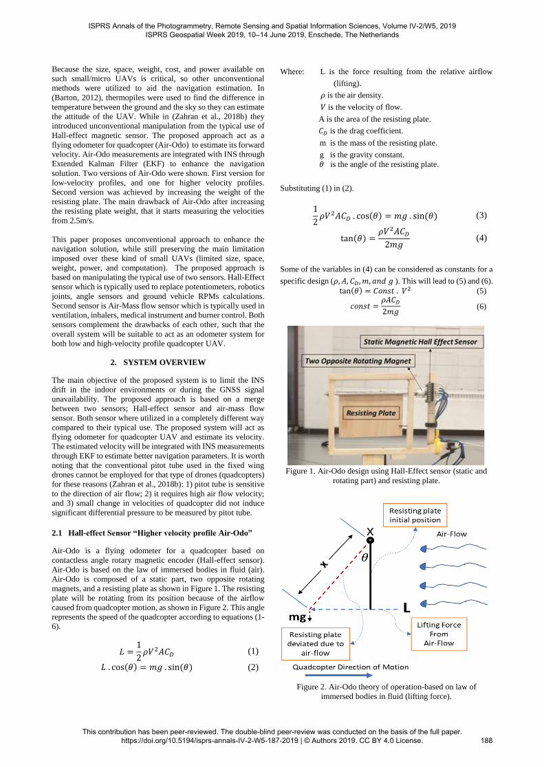
Air-Odo is a flying odometer for a quadcopter based on
contactless angle rotary magnetic encoder (Hall-effect sensor).
Air-Odo is based on the law of immersed bodies in fluid (air).
Air-Odo is composed of a static part, two opposite rotating
magnets, and a resisting plate as shown in Figure 1. The resisting
plate will be rotating from its position because of the airflow
caused from quadcopter motion, as shown in Figure 2. This angle
represents the speed of the quadcopter according to equations (1-
6).
𝐿 =1
2𝜌𝑉2𝐴𝐶𝐷 (1)
𝐿 . cos(𝜃) = 𝑚𝑔 . sin (𝜃) (2)
Where: L is the force resulting from the relative airflow
(lifting).
𝜌 is the air density.
𝑉 is the velocity of flow.
A is the area of the resisting plate.
𝐶𝐷 is the drag coefficient.
m is the mass of the resisting plate.
g is the gravity constant.
𝜃 is the angle of the resisting plate.
Substituting (1) in (2).
1
2𝜌𝑉2𝐴𝐶𝐷 . cos(𝜃) = 𝑚𝑔 . sin (𝜃) (3)
tan(𝜃) =𝜌𝑉2𝐴𝐶𝐷
2𝑚𝑔 (4)
Some of the variables in (4) can be considered as constants for a
specific design (𝜌, 𝐴, 𝐶𝐷, 𝑚, 𝑎𝑛𝑑 𝑔 ). This will lead to (5) and (6).
tan(𝜃) = 𝐶𝑜𝑛𝑠𝑡 . 𝑉2 (5)
𝑐𝑜𝑛𝑠𝑡 =𝜌𝐴𝐶𝐷
2𝑚𝑔 (6)
Figure 1. Air-Odo design using Hall-Effect sensor (static and
rotating part) and resisting plate.
Figure 2. Air-Odo theory of operation-based on law of
immersed bodies in fluid (lifting force).
ISPRS Annals of the Photogrammetry, Remote Sensing and Spatial Information Sciences, Volume IV-2/W5, 2019 ISPRS Geospatial Week 2019, 10–14 June 2019, Enschede, The Netherlands
This contribution has been peer-reviewed. The double-blind peer-review was conducted on the basis of the full paper. https://doi.org/10.5194/isprs-annals-IV-2-W5-187-2019 | © Authors 2019. CC BY 4.0 License.
188

According to the weight of the resisting plate, the dynamic range
of velocities that can be measured by Air-Odo can be altered, and
the constant value can be calibrated as shown in (Zahran et al.,
2018b). In its current state Air-Odo can measure from 0.7 m/s to
5 m/s. By increasing the resisting plate weight (8 grams) as
shown in Figure 3, the velocities range changed to be from 2.5m/s
up to 10m/s. Figure 4 represents the measurements from Air-Odo
with and without weight in a wind tunnel experiment to estimate
the constant value shown in equation (6).
Figure 3. Air-Odo with additional weight (8 grams) added to the
resisting plate to increase its velocity dynamic range.
Figure 4. Air-Odo angle measurements and Wind-tunnel
velocities relationship.
In order to use the higher velocity dynamic range Air-Odo,
another sensor is used to account for the low-velocity profiles
“Air-mass flow sensor”.
2.2 Air-mass flow sensor
Air-mass flow/ Mass-Flow sensor is shown in Figure 5, the flow
meter is typically used in vast applications like medical purposes
(respiration applications), Heating, Ventilation, and Air
Conditioning (HVAC) applications, burner control, and fuel cell
control. In this proposed system Air-mass flow is used as an
odometer for quadcopter to measure the induced air resulting
from quadcopter motion.
Figure 5. Mass-Flow Sensor
Mass flow meter sensor can measure the flow of air and non-
aggressive gases with high output rate up to 2kHz.Although
Mass-flow meter can measure higher speeds than the quadcopter
velocities, although it is sensitive to the direction of air flow. This
sensitivity will limit its capabilities when it is mounted on the
quadcopter, because of the way the quadcopter moves. The
quadcopter tends to tilt towards the direction of motion, and this
tilting angle increase when the velocity increases, which makes
the Mass flow meter at higher velocities on board of the
quadcopter useless as shown in Figure 6.
Figure 6. Quadcopter tilting (Higher velocities) and its effect on
Mass-Flow meter.
2.3 Fusion Filter
The measurements from both systems (velocity) were fused
together based on velocity criteria. The velocity from the Mass-
flow meter is considered as long as the velocity is lower than
2.5m/s, and higher than that the velocity is taken from Air-Odo.
The overall velocities (output of both system fused together) are
integrated with INS measurements through a loosely coupled
EKF as shown in Figure 7.
Figure 7. Proposed approach work scheme/integration through
Extended Kalman Filter.
3. HARDWARE ASSEMBLY AND EXPERIMENT
3.1 Hardware
The quadcopter used is a commercial small size on the shelf
quadcopter (3DR SOLO).This drone is equipped with MEMS-
based low-cost IMU (MPU 9000 series), and a U-blox GPS. On
the other hand, Air-Odo system and the Mass flow-meter is
connected to LattePanda onboard Mini PC for data logging and
processing. A flight was conducted indoor to verify the ability of
the proposed system to enhance the navigation system parameters
estimation during GNSS signal outage. MarvelMind indoor
positioning system (consist of 4 stationary beacons distributed
around the four corners of the field, and one moving beacon
ISPRS Annals of the Photogrammetry, Remote Sensing and Spatial Information Sciences, Volume IV-2/W5, 2019 ISPRS Geospatial Week 2019, 10–14 June 2019, Enschede, The Netherlands
This contribution has been peer-reviewed. The double-blind peer-review was conducted on the basis of the full paper. https://doi.org/10.5194/isprs-annals-IV-2-W5-187-2019 | © Authors 2019. CC BY 4.0 License.
189

mounted on the quadcopter) was used as a reference solution. The
overall system is shown in Figure 8.
Figure 8. 3DR quadcopter equipped with all the equipment (Air-
Odo, Mass-Air flow, and MarvelMind indoor positioning
system) for the indoor flying experiment
3.2 Experiment
The flight extended for around 260 seconds, with varying
velocities from 0 to 6 m/s. Figure 9 shows the velocity from Air-
Odo alone with additional weight added to the resisting plate
compared to the reference velocity.
Figure 9. Air-Odo velocity estimation compared to the reference
velocity, and the red circles showing that this version of Air-
Odo with additional weight can't sense the lower velocities
profile.
As shown in the previous figure that Air-Odo can’t sense lower
velocities (as shown in the blue circles). Both velocities from Air-
Odo and Mass-flow meter will be merged together to account for
lower and higher.
Figure 10 shows the benefit of the proposed system (merging the
measurements from Air-Odo with additional weight and mass
flow sensor) to account for both lower and higher quadcopter
velocities.
Figure 10. Velocity estimation from the proposed approach
(Air-Odo and Mass-Flow sensor) compared to the reference
velocity, showing the ability of the proposed system to sense
lower and higher velocities compared to Air-Odo alone with
additional weight added.
3.2.1 INS Dead-Reckoning Solution: Figure 11 shows the
reference trajectory compared to the solution from the INS
solution This experiment ensures the inability of the low-cost
INS to estimate the navigation unknowns, during the absence of
an absolute positioning system.
Figure 11. The solution of the INS -Stand alone system during
GNSS signal outage is compared to the reference trajectory
showing the massive drift happened during this outage period.
Also, Figure 12 and Table 1 show the errors in the north and east
direction during this GNSS outage period. The results prove the
massive drift happened during this period which reached
hundreds of meters.
INS-Dead-Reckoning Error (m)
RMSE North 140.91
Maximum Error North 332.7
RMSE East 127.14
Maximum Error East 304
Table 1. INS dead-reckoning solution errors during 60 Secs of
GNSS signal outage.
ISPRS Annals of the Photogrammetry, Remote Sensing and Spatial Information Sciences, Volume IV-2/W5, 2019 ISPRS Geospatial Week 2019, 10–14 June 2019, Enschede, The Netherlands
This contribution has been peer-reviewed. The double-blind peer-review was conducted on the basis of the full paper. https://doi.org/10.5194/isprs-annals-IV-2-W5-187-2019 | © Authors 2019. CC BY 4.0 License.
190

Figure 12. Errors in north and east directions of the INS -
Standalone system during GNSS signal outage for 60 Secs.
3.2.2 Air-Odo – INS integration (60 Secs Outage): This test
aims to evaluate the performance of the Air-Odo system only
with the added additional weight. Figure 13 shows the obtained
solution from Air-Odo alone with the additional weight
compared to the reference trajectory.
Figure 13. Solution of integrating Air-Odo alone with additional
weight and INS during 60 Secs of GNSS signal outage.
As seen in the previous figure that the solution of that integration
cause trajectory shrinking, as the Air-Odo system with additional
weight can measure velocity starting from 2.5 m/s, and below this
velocity it will predict that the quadcopter is hovering (zero
velocity).
Table 2 shows the RMSE and maximum errors in both north and
east direction. While Figure 14 shows the error trend during the
flight in both directions as well.
Proposed approach - INS Error (m)
RMSE North 4.69
Maximum Error North 13.17
RMSE East 4.37
Maximum Error East 10.08
Table 2. Air-Odo – INS performance during 60 Secs of GNSS
signal outage.
Figure 14. Errors in north and east directions of the Air-Odo
alone with additional weight and INS solution during GNSS
signal outage for 60 Secs.
3.2.3 Proposed approach- INS integration (60 Secs
Outage): The following Figures 15 and 16 show the ability of
the proposed approach to limit the drift of the INS during the
absence of an absolute positioning system.
Figure 15. Solution of the proposed approach integrated with
INS during 60 Secs of GNSS signal outage.
Both Figures 15 and 16 proved that the proposed approach was
able to limit the massive drift exhibited by the INS system as a
standalone system. The RMSE reached 2.83 and 1.31 meters in
the east and north direction respectively as seen in Table 3.
Proposed approach - INS Error (m)
RMSE North 1.31
Maximum Error North 4.67
RMSE East 2.83
Maximum Error East 6.39
Table 3. Proposed approach performance errors during 60 Secs
of GNSS signal outage.
Comparing Table 3 to Table 2 results, prove the significance of
merging between Air-Odo and mass flow sensor to account for
lower and higher velocity profiles.
ISPRS Annals of the Photogrammetry, Remote Sensing and Spatial Information Sciences, Volume IV-2/W5, 2019 ISPRS Geospatial Week 2019, 10–14 June 2019, Enschede, The Netherlands
This contribution has been peer-reviewed. The double-blind peer-review was conducted on the basis of the full paper. https://doi.org/10.5194/isprs-annals-IV-2-W5-187-2019 | © Authors 2019. CC BY 4.0 License.
191

Figure 16. Errors in the north and east direction of the proposed
approach integrated with INS during 60 Secs of GNSS signal
outage.
3.2.4 Proposed approach- INS integration (120 Secs
Outage): This experiment is to show that the proposed approach
can limit the drift for a longer outage period (2 min). The
integration results between the proposed approach and the
reference trajectory are shown in Figure 16.
Figure 17. Solution of the proposed approach integrated with
INS during 120 Secs of GNSS signal outage.
As shown in the Figures 17 and 18 that even with 2 min of
complete GNSS outage, the proposed approach is still able to
bound the drift exhibited by the INS with RMSE in Table 4.
Proposed approach - INS Error (m)
RMSE North 2.00
Maximum Error North 4.67
RMSE East 2.88
Maximum Error East 6.39
Table 4. Proposed approach performance errors during 120 Secs
of GNSS signal outage.
Figure 18. Errors in the north and east direction of the proposed
approach INS integration during 120 Secs of GNSS outage.
As shown in the previous 2 experiments that for outage periods
reached 2 complete minutes of GNSS signals outage the
proposed approach still overcome the INS dead-reckoning
solution by more than 99 %.
3.2.5 Proposed approach- INS integration (260 Secs
Outage): This last experiment presented in Figure 19 and 20 is
to stand on the ability of the proposed approach to still aid the
navigation system during longer outage periods (more than 4
minutes of complete absolute positioning system outage).
Figure 19. Solution of the proposed approach integrated with
INS during 260 Secs of GNSS signal outage
Proposed approach - INS Error (m)
RMSE North 2.31
Maximum Error North 6.22
RMSE East 4.69
Maximum Error East 10.6
Table 5. Proposed approach performance errors during 260 Secs
of GNSS signal outage.
This test showed that for an even longer period of GNSS outage
the performance of the proposed approach is still confined within
ISPRS Annals of the Photogrammetry, Remote Sensing and Spatial Information Sciences, Volume IV-2/W5, 2019 ISPRS Geospatial Week 2019, 10–14 June 2019, Enschede, The Netherlands
This contribution has been peer-reviewed. The double-blind peer-review was conducted on the basis of the full paper. https://doi.org/10.5194/isprs-annals-IV-2-W5-187-2019 | © Authors 2019. CC BY 4.0 License.
192

RMSE 4.69 and 2.31 meters in the east and north direction
respectively as shown in Table 5.
Figure 20. Errors in the north and east direction of the proposed
approach integrated with INS during 260 Secs of GNSS signal
outage.
To show how this low cost(Air-Odo around 20 CAD, and mass-
flow meter around 60 CAD), Lightweight (the overall system
weight is less than 85 grams), low power consumption (the
overall system power consumption is less than 200 mW) and
small size system greatly enhance the performance of the
navigation system, some high end INS systems (“IMU-FSAS
Inertial Measurement Unit,” n.d.), that costs thousands of dollars
claims 4.4 RMSE during 60 Secs of GNSS outage, which is still
achieved with the proposed approach within 260 Secs GNSS
outage.
4. CONCLUSION
Due to the vital rule that the drones play in our current daily lives,
it must be versatile to do any task in all circumstances. Small
drones mainly depend on integrated GNSS system and low-cost
INS system to estimate the navigation parameters. Without
GNSS system, low-cost INS exhibit massive drift. Other aiding
sensors are utilized to bound the INS drift and enhance the
navigation system unknowns’ estimation. This paper proposes a
combination of two systems that complement each other
weaknesses. These systems act as an odometer system for the
quadcopter. The first system is Air-Odo which is based on Hall-
Effect sensor to measure the forward velocity of the quadcopter.
Air-Odo working principle is based on the law of immersed
bodies in fluids. The dynamic velocities range of the Air-Odo can
be adjusted according to the resisting plate weight. To
accommodate for higher velocities the dynamic range of the Air-
Odo is changed to cover velocities ranges between 2.5 m/s to 10
m/s. In order to account for the velocities below 2.5m/s other
sensor was used (Mass flow sensor). Although Mass-Flow sensor
has the ability to measure higher velocities, but its sensitive to the
direction of air. Due to quadcopter dynamics way of motion,
which requires the quadcopter to tilt more as the velocity
increase, Mass-Flow sensor is not useful for quadcopter high tilt
motion (higher velocities). Air-Mass flow limitations will be
covered by Air-Odo. The proposed system was verified by
hardware experiment which includes more than four minutes
(260 Secs) of complete GNSS signals outage in indoor field. The
results showed a great enhancement in the navigation system
reached more than 99% compared to INS as stand alone system.
5. PATENT
Air-Odo is filed on June 6, 2018 in SYSTEM AND METHOD
FOR DETERMINING AIRSPEED, U.S. Provisional
Application No. 62/681,233.
ACKNOWLEDGEMENTS
This research is under the supervision and funding of Prof. Naser
El-Sheimy from NSERC and Canada Research Chairs programs.
6. REFERENCES
Bailey, T., Durrant-Whyte, H., 2006. Simultaneous
localization and mapping (SLAM): part II. IEEE Robot.
Autom. Mag. 13, 108–117.
https://doi.org/10.1109/MRA.2006.1678144
Barton, J.D., 2012. Fundamentals of Small Unmanned
Aircraft Flight. Johns Hopkins APL Tech. Dig. 31, 132–
149.
Caballero, F., Merino, L., Ferruz, J., Ollero, A., 2009.
Unmanned Aerial Vehicle Localization Based on
Monocular Vision and Online Mosaicking. J. Intell. Robot.
Syst. 55, 323–343. https://doi.org/10.1007/s10846-008-
9305-7
Chao, H., Gu, Y., Napolitano, M., 2013. A survey of
optical flow techniques for UAV navigation applications,
in: 2013 International Conference on Unmanned Aircraft
Systems (ICUAS). Presented at the 2013 International
Conference on Unmanned Aircraft Systems (ICUAS), pp.
710–716. https://doi.org/10.1109/ICUAS.2013.6564752
Enhanced UAV navigation in GNSS denied environment
using repeated dynamics pattern recognition - IEEE
Conference Publication [WWW Document], n.d. URL
https://ieeexplore-ieee-
org.ezproxy.lib.ucalgary.ca/document/8373497 (accessed
9.26.18).
Hemann, G., Singh, S., Kaess, M., 2016. Long-range GPS-
denied aerial inertial navigation with LIDAR localization,
in: Intelligent Robots and Systems (IROS), 2016
IEEE/RSJ International Conference On. IEEE, pp. 1659–
1666.
IMU-FSAS Inertial Measurement Unit [WWW
Document], n.d. . Canal Geomat. URL
http://www.canalgeomatics.com/product/novatel-imu-
fsas-inertial-measurement-unit/ (accessed 12.11.18).
Kumar, G.A., Patil, A.K., Patil, R., Park, S.S., Chai, Y.H.,
2017. A LiDAR and IMU Integrated Indoor Navigation
System for UAVs and Its Application in Real-Time
Pipeline Classification. Sensors 17.
https://doi.org/10.3390/s17061268
Lu, Y., Xue, Z., Xia, G.-S., Zhang, L., 2018. A survey on
vision-based UAV navigation. Geo-Spat. Inf. Sci. 21, 21–
32. https://doi.org/10.1080/10095020.2017.1420509
ISPRS Annals of the Photogrammetry, Remote Sensing and Spatial Information Sciences, Volume IV-2/W5, 2019 ISPRS Geospatial Week 2019, 10–14 June 2019, Enschede, The Netherlands
This contribution has been peer-reviewed. The double-blind peer-review was conducted on the basis of the full paper. https://doi.org/10.5194/isprs-annals-IV-2-W5-187-2019 | © Authors 2019. CC BY 4.0 License.
193
Mohamed, H.A., Moussa, A.M., Elhabiby, M.M., El-
Sheimy, N., Sesay, A.B., 2017. CORNER FEATURES
AIDED INDOOR SLAM FOR UNMANNED
VEHICLES, in: The 10th International Symposium on
Mobile Mapping Technology. Presented at the MMT2017,
ISPRS, Cairo, Egypt.
Mostafa, M.M., Moussa, A.M., El-Sheimy, Naser, Sesay, Abu
B., "Optical Flow Based Approach for Vision Aided Inertial
Navigation Using Regression Trees," Proceedings of the 2017
International Technical Meeting of The Institute of Navigation,
Monterey, California, January 2017, pp. 856-865.
https://doi.org/10.33012/2017.14898
Mustafah, Y.M., Azman, A.W., Akbar, F., 2012. Indoor
UAV Positioning Using Stereo Vision Sensor. Procedia
Eng., International Symposium on Robotics and Intelligent
Sensors 2012 (IRIS 2012) 41, 575–579.
https://doi.org/10.1016/j.proeng.2012.07.214
Noureldin, A., Karamat, T.B., Georgy, J., 2013.
Fundamentals of Inertial Navigation, Satellite-based
Positioning and their Integration. Springer Berlin
Heidelberg, Berlin, Heidelberg.
https://doi.org/10.1007/978-3-642-30466-8
Sheta, B., 2012. Vision Based Navigation (VBN) of
Unmanned Aerial Vehicles (UAV) (Thesis). University of
Calgary. http://dx.doi.org/10.11575/PRISM/28646
Tang, J., Chen, Y., Niu, X., Wang, L., Chen, L., Liu, J.,
Shi, C., Hyyppä, J., 2015. LiDAR Scan Matching Aided
Inertial Navigation System in GNSS-Denied
Environments. Sensors 15, 16710–16728.
https://doi.org/10.3390/s150716710
Valavanis, K.P., Vachtsevanos, G.J., 2015. Future of
Unmanned Aviation, in: Valavanis, K.P., Vachtsevanos,
G.J. (Eds.), Handbook of Unmanned Aerial Vehicles.
Springer Netherlands, Dordrecht, pp. 2993–3009.
https://doi.org/10.1007/978-90-481-9707-1_95
Wang, T., Wang, C., Liang, J., Chen, Y., Zhang, Y., 2013.
Vision-Aided Inertial Navigation for Small Unmanned
Aerial Vehicles in GPS-Denied Environments. Int. J. Adv.
Robot. Syst. 10, 276. https://doi.org/10.5772/56660
Zahran, S., Moussa, A., Sesay, A., El-Sheimy, N., 2018a.
ENHANCEMENT OF REAL-TIME SCAN MATCHING
FOR UAV INDOOR NAVIGATION USING VEHICLE
MODEL. ISPRS Ann. Photogramm. Remote Sens. Spat.
Inf. Sci. IV–1, 171–178. https://doi.org/10.5194/isprs-
annals-IV-1-171-2018
Zahran, S., Moussa, A., Sesay, A.B., El-Sheimy, N.,
2018b. A New Velocity Meter based on Hall Effect
Sensors for UAV Indoor Navigation. IEEE Sens. J. 1–1.
https://doi.org/10.1109/JSEN.2018.2890094
Zhang, C., Chen, J., Song, C., Xu, J., 2014. An UAV
navigation aided with computer vision, in: The 26th
Chinese Control and Decision Conference (2014 CCDC).
Presented at the The 26th Chinese Control and Decision
Conference (2014 CCDC), pp. 5297–5301.
https://doi.org/10.1109/CCDC.2014.6852209
Zhang, J., Liu, W., Wu, Y., 2011. Novel Technique for
Vision-Based UAV Navigation. IEEE Trans. Aerosp.
Electron. Syst. 47, 2731–2741.
https://doi.org/10.1109/TAES.2011.6034661
ISPRS Annals of the Photogrammetry, Remote Sensing and Spatial Information Sciences, Volume IV-2/W5, 2019 ISPRS Geospatial Week 2019, 10–14 June 2019, Enschede, The Netherlands
This contribution has been peer-reviewed. The double-blind peer-review was conducted on the basis of the full paper. https://doi.org/10.5194/isprs-annals-IV-2-W5-187-2019 | © Authors 2019. CC BY 4.0 License.
194
Top Related