


Languages
Pages
Legal

ENERGY FROM WASTE
WE MAkE ThE WORld A clEANER plAcE

Steinmüller Babcock Environment – innovative and global
WE MAkE ThE WORld A clEANER plAcE
Steinmüller Babcock Environment (SBEng) – a name that stands for cutting-edge technology in thermal waste treat-ment and flue gas cleaning. Our company develops, plans, builds and manages complete plants as well as individual key components. Our products are all “Made in Germany” and over 1.200 reference plants worldwide stand testament to our expertise. The company is based in Gummersbach, in the heart of North Rhine-Westphalia, the most heavily populated of the German federal states. Around 300 employees work here for SBEng or, if required, on-site at our plants around the globe. We develop plant concepts in close coordination with our customers, therefore the plants are tailored to the requirements of the individual markets. We are supported by our subsidiary Steinmüller Babcock Engineering Consulting Co. Ltd., which is situated in Shanghai.
Worldwide, our plants offer solutions to the increasingly pressing question: “How can the quantities of waste arising be treated in an environmentally friendly and energy-efficient manner?”
Tradition breeds progress and development
We have been developing solutions for environmental protec-tion for over 50 years – five decades in which we have com-bined tradition and experience with research and innovation. SBEng products have therefore contributed to modern waste disposal being seen as a clean, environmentally friendly tech-nology. Thermal waste treatment today: a safe process, eco-nomically and ecologically sound. Energy from Waste
Our partnership: strength in numbers
Steinmüller Babcock Environment (SBEng) is part of the NSENGI group (Nippon Steel & Sumikin Engineering Co., Ltd), one of the leading environmental technology compa-nies in Asia. Being one of the most important subsidiaries of Nippon Steel & Sumitomo Metal (NSSMC), the second lar-gest steel producer in the world, NSENGI was initially set up as a development division of NSSMC in 1974. In 2006 it was outsourced as an independent unit of NSSMC, but remained fully-owned. NSENGI employs more than 4.000 people and with 42 reference plants (40 in Japan and 2 in South Korea) it is the world’s leading supplier of waste gasification and melting technology with its Direct Melting Systems (DMS).
Our origins: historic growth
Our roots stretch back more than 150 years. SBEng was created by pooling the environmental technology know-how of three companies steeped in tradition: Deutsche Babcock Anlagen
2

GmbH, Noell KRS Energie- und Umwelttechnik GmbH and L & C Steinmüller GmbH. These origins have shaped what we are to-day and entail a sense of duty: for our customers we are a part-ner that is both competent and innovative when it comes to building environmental technologies. Now and in the future.
Our Energy from Waste: robust solutions designed to last
We plan and implement plants for thermal treatment of a wide range of different waste materials. Our services are specifically tailored to the respective requirements of our clients.
Irrespective of whether we are supplying the entire process chain or just individual components, we are constantly opti-mizing our products and processes to ensure we always offer long-lasting, efficient and cost-effective solutions.
Our Flue Gas Cleaning: plan for the long term, act sustainable
One of the greatest challenges of our time is to protect the quality of the air we breathe. Our flue gas cleaning plants for power stations and industrial facilities play a significant role towards this by complying with the most stringent of environ-mental standards. The new plants and retrofit measures of SBEng guarantee great efficiency with maximum availability.
After Sales ServiceFlue Gas Cleaning
Contents
Steinmüller Babcock Environment – innovative and global ...................................................................................................... 2Thermal waste treatment – an environmentally friendly process ............................................................................................ 4The process of waste incineration – clean and safe ................................................................................................................... 6The Steinmüller Babcock forward moving grate – always under fire ...................................................................................... 8The boiler – full of energy ......................................................................................................................................................... 10Ash and clinker – a lot left to offer ............................................................................................................................................12Combustion control system – for optimal running ...................................................................................................................14Hazardous waste – the end of the line for dangerous refuse ................................................................................................. 16Flue Gas Cleaning – for pure air ................................................................................................................................................. 18One company – many roles ........................................................................................................................................................ 20Our After Sales Service – always at your side ........................................................................................................................... 22Worldwide active – a selection of our 1,200 reference plants ................................................................................................ 24
After all, as one of the market leaders, we are fully aware of our responsibility to act sustainable – for the sake of our clients and the environment.
3
Thermal waste treatment – an environmentally friendly process
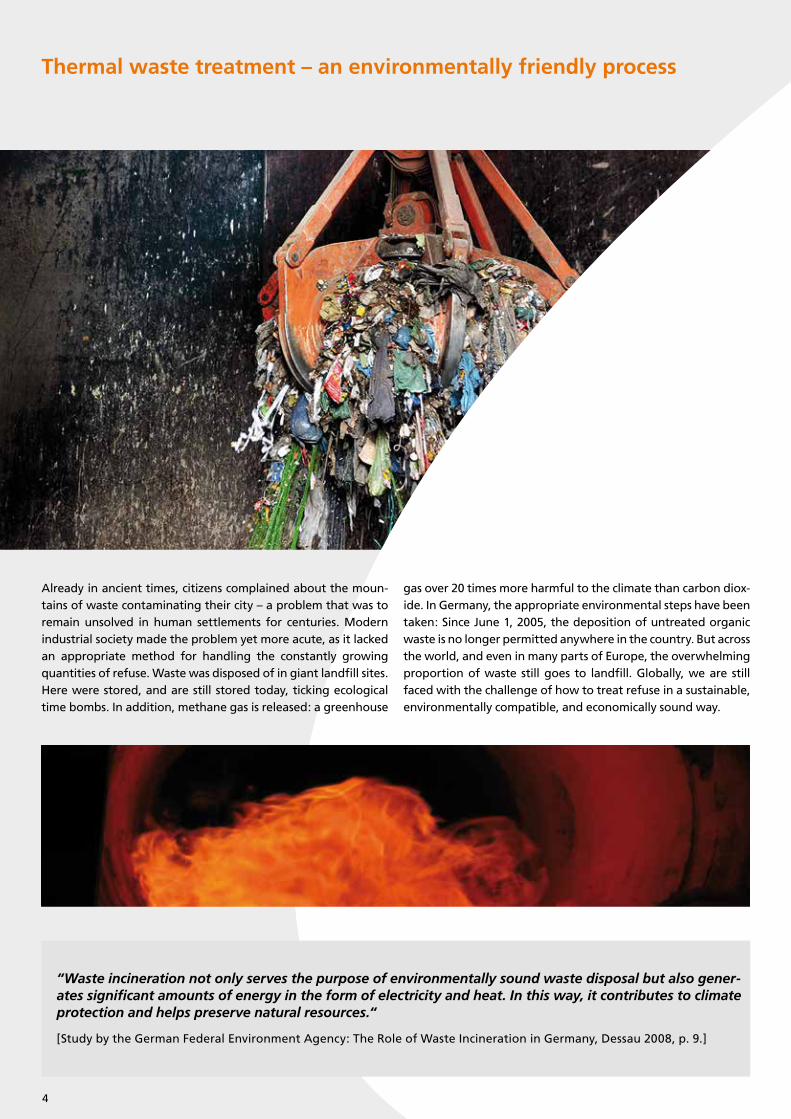
Already in ancient times, citizens complained about the moun-tains of waste contaminating their city – a problem that was to remain unsolved in human settlements for centuries. Modern industrial society made the problem yet more acute, as it lacked an appropriate method for handling the constantly growing quantities of refuse. Waste was disposed of in giant landfill sites. Here were stored, and are still stored today, ticking ecological time bombs. In addition, methane gas is released: a greenhouse
gas over 20 times more harmful to the climate than carbon diox-ide. In Germany, the appropriate environmental steps have been taken: Since June 1, 2005, the deposition of untreated organic waste is no longer permitted anywhere in the country. But across the world, and even in many parts of Europe, the overwhelming proportion of waste still goes to landfill. Globally, we are still faced with the challenge of how to treat refuse in a sustainable, environmentally compatible, and economically sound way.
“Waste incineration not only serves the purpose of environmentally sound waste disposal but also gener-ates significant amounts of energy in the form of electricity and heat. In this way, it contributes to climate protection and helps preserve natural resources.“
[Study by the German Federal Environment Agency: The Role of Waste Incineration in Germany, Dessau 2008, p. 9.]
4
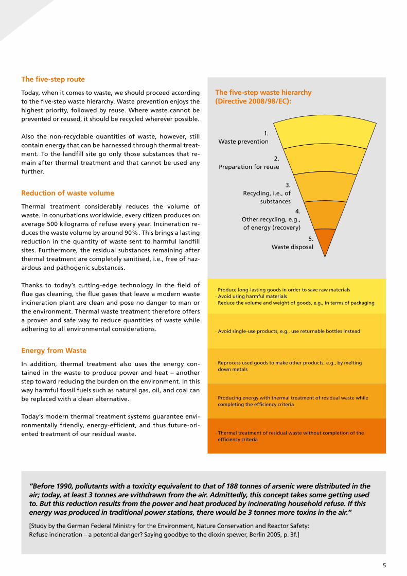
The five-step route
Today, when it comes to waste, we should proceed according to the five-step waste hierarchy. Waste prevention enjoys the highest priority, followed by reuse. Where waste cannot be prevented or reused, it should be recycled wherever possible.
Also the non-recyclable quantities of waste, however, still contain energy that can be harnessed through thermal treat-ment. To the landfill site go only those substances that re-main after thermal treatment and that cannot be used any further.
Reduction of waste volume
Thermal treatment considerably reduces the volume of waste. In conurbations worldwide, every citizen produces on average 500 kilograms of refuse every year. Incineration re-duces the waste volume by around 90%. This brings a lasting reduction in the quantity of waste sent to harmful landfill sites. Furthermore, the residual substances remaining after thermal treatment are completely sanitised, i.e., free of haz-ardous and pathogenic substances.
Thanks to today’s cutting-edge technology in the field of flue gas cleaning, the flue gases that leave a modern waste incineration plant are clean and pose no danger to man or the environment. Thermal waste treatment therefore offers a proven and safe way to reduce quantities of waste while adhering to all environmental considerations.
Energy from Waste
In addition, thermal treatment also uses the energy con-tained in the waste to produce power and heat – another step toward reducing the burden on the environment. In this way harmful fossil fuels such as natural gas, oil, and coal can be replaced with a clean alternative.
Today’s modern thermal treatment systems guarantee envi-ronmentally friendly, energy-efficient, and thus future-ori-ented treatment of our residual waste.
“Before 1990, pollutants with a toxicity equivalent to that of 188 tonnes of arsenic were distributed in theair; today, at least 3 tonnes are withdrawn from the air. Admittedly, this concept takes some getting usedto. But this reduction results from the power and heat produced by incinerating household refuse. If this energy was produced in traditional power stations, there would be 3 tonnes more toxins in the air.“
[Study by the German Federal Ministry for the Environment, Nature Conservation and Reactor Safety:Refuse incineration – a potential danger? Saying goodbye to the dioxin spewer, Berlin 2005, p. 3f.]
· Thermal treatment of residual waste without completion of the efficiency criteria
· Producing energy with thermal treatment of residual waste while completing the efficiency criteria
· Reprocess used goods to make other products, e.g., by melting down metals
· Avoid single-use products, e.g., use returnable bottles instead
· Produce long-lasting goods in order to save raw materials· Avoid using harmful materials· Reduce the volume and weight of goods, e.g., in terms of packaging
1. Waste prevention
2. Preparation for reuse
3. Recycling, i.e., of
substances
4. Other recycling, e.g., of energy (recovery)
5. Waste disposal
The five-step waste hierarchy(Directive 2008/98/EC):
5

Waste bunker: The waste delivered is stored in the waste bunker 1 and ho-mogenised by the crane. The crane then transports the mixed waste to the feeding hopper 2 . Via the chute the waste arrives at the feeder 3 which pushes the waste onto the combustion grate in accordance with the firing control requirements.
Forward moving grate: The waste incine-ration process takes place on the grate 4 which comprises of grate bar rows with grate bars side by side. The grate bar rows are arranged overlapping one behind the other. Every second row moves alternately forth and back. The waste and later the slag material is transported by these rows to the end of the grate where the slag is discharged into the slag extractor 5 .
Slag extractor: The slag extractor 5 is partially filled with water resulting in an air exclusion between the environ-ment and the furnace itself. The slag falling from the grate is cooled in the water bath and conveyed by the ram of the slag extractor to a vibrating con-veyor which transports the slag to the slag bunker 6 .
Fire on grate: The plant operators mo-nitor the incineration process on the grate 7 with CCTV. The air required for incineration (primary air) is control-led supplied from below through the grate. To obtain an optimal burnout of the flue gases, additional air (se-condary air) is injected above the grate. In the boiler the hot flue gases are then
cooled down to the respective desired flue gas outlet temperature.
Boiler: The heat of the flue gases is used to heat demineralised water in the economiser heating surfaces 10 . This so-called boiler feed water is then fed into the drum 11 which feeds the evaporator operated in natural circula-tion.
The water-steam mixture arising in the walls of the boiler radiation pas-ses (evaporator) 8 is separated in the drum into water and steam 11 . The steam is directed to the superheater heating surfaces 9 . After heating up to the specified temperature, the live steam is led to the turbine 12 .
The process of waste incineration – clean and safe
Waste bunker Forward moving grate Slag extractor Fire on grate Boiler drum
1
2
3
4
56
7
8 9
11
12
6

Turbine: Inside the turbine 12 , the over-heated steam is relieved to turn the rotor of the turbine and is then condensed. The energy released during this process is utili-sed in the attached generator to produce electricity. The electricity is fed into the pu-blic grid. The condensate is collected in the feed water tank 13 and finally returned to the boiler. Alternatively part of the energy can be fed to local or district heat networks or used as process steam (com-bined heat and power production).
Spray absorber: In the spray absorber top 14 , water and lime milk are injected into the flue gas from the boiler. Flowing down the absorber cooling achieves op-timum reaction conditions for capturing the acidic pollutants in particular.
inuously discharged and conveyed into silos 17 for disposal.
ID-fan: The ID-fan 18 keeps underpres-sure in the incineration process and leads the flue gas through the boiler and the flue gas cleaning system. Underpressure also ensures system thightness regarding flue gas.
Stack: The cleaned flue gas is leaving the process to atmosphere via the stack 19 . In order to further improve efficiency, more and more condensation heat ex- changers are installed in waste incinera-tion plants. This means that clean, pure water vapour is emitted from the stack in the form of white clouds which dissolve – a sign of optimum energy utilisation.
After cooling the flue gas, recirculate (re-action products separated in the fabric filter), fresh dry absorbent and activated carbon are injected into the entrained-flow reactor 15 .
Fabric filter: The pollutants still contained in the flue gas react chemically or are ad-sorbed by the solids and thereby precipi-tated with the fly ash in the subsequent fabric filter 16 . As a filter medium several thousand filter hoses ensure that the filte-red flue gas safely complies with all legal and environmental requirements. A high percentage of the reaction products is re-circulated ahead of the fabric filter. The recirculate can be moistened to optimise utilisation of the feed materials. A parti-al flow of the reaction products is cont-
Spray absorber Fabric filter penthouse Filter hoses ID-fan Stack
Waste bunkerWaste feed hopperFeederForward moving grateSlag extractor
Slag bunkerFire on grateEvaporatorSuperheaterEconomiser
Boiler drumTurbineFeed water tankSpray absorberFlow reactor
Fabric filterSilosID-fanStack
1 6 11
12
13
14
15
2 7
3 8
4 9
5 10
16
17
18
19
10
13
14
15
16
17
18
19
7

The Steinmüller Babcock forward moving grate – always under fire
The Steinmüller Babcock forward moving grate is the central component of a waste incineration plant. Whether air- or water-cooled, this forward moving grate performs miracle transformations as it turns waste into energy. In constant motion, it leads the inserted refuse through several phases of incineration – from drying at the beginning of the grate to the main combustion zone in the centre of the grate and to the slag burnout at the end of the grate.
The grate has a modular construction. The optimum grate size can therefore be achieved for every application. The spectrum of combustibles ranges from household refuse with a high level of moisture to high-calorific plastics. The maximum throughput capacity per line is approximately 400,000 tonnes per year, respectively about 1100 tonnes per day. Thanks to decades of experience, sturdy construction,
and constant development, the air- and watercooled for-ward moving grates always represent the latest in incinera-tion technology.
Optimal burnout
The overall concept of the forward moving grate speaks for it- self. It provides during the combustion process, for example, in each combustion zone individual combustion air control as well as individual grate velocity for transporting the waste. Both features are ensured by our advanced combustion control sys-tem. In order to achieve even better burnout quality, our grate system works with two grate steps which ensure that the waste is repeatedly broken up and mixed during the combustion pro-cess. This delivers a perfect burnout and the strict German and European regulations are reliably adhered to.
Cautious estimations assume that using waste to produce energy now saves, on average, a quantity of fossil fuels corresponding to the needs of around 700,000 citizens.
Incineration of around 2 kg of household refuse with a calorific value of around 8,000 kJ/kg can produce 1 kWh of power. This can light a 40-watt light bulb for some 25 hours. The amount of energy in a well-filled 60-litre household bin can run the light bulb for almost an entire week.
8
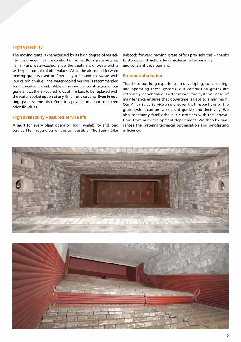
High versatility
The moving grate is characterised by its high degree of versati-lity. It is divided into five combustion zones. Both grate systems, i.e., air- and water-cooled, allow the treatment of waste with a wide spectrum of calorific values. While the air-cooled forward moving grate is used preferentially for municipal waste with low calorific values, the water-cooled version is recommended for high-calorific combustibles. The modular construction of our grate allows the air-cooled rows of fire bars to be replaced with the water-cooled option at any time – or vice versa. Even in exis-ting grate systems, therefore, it is possible to adapt to altered calorific values.
High availability – assured service life
A must for every plant operator: high availability and long service life – regardless of the combustible. The Steinmüller
Babcock forward moving grate offers precisely this – thanks to sturdy construction, long professional experience,and constant development.
Economical solution
Thanks to our long experience in developing, constructing, and operating these systems, our combustion grates are extremely dependable. Furthermore, the systems’ ease of maintenance ensures that downtime is kept to a minimum. Our After Sales Service also ensures that inspections of the grate system can be carried out quickly and decisively. We also constantly familiarise our customers with the innova-tions from our development department. We thereby gua-rantee the system’s technical optimisation and longlasting efficiency.
9
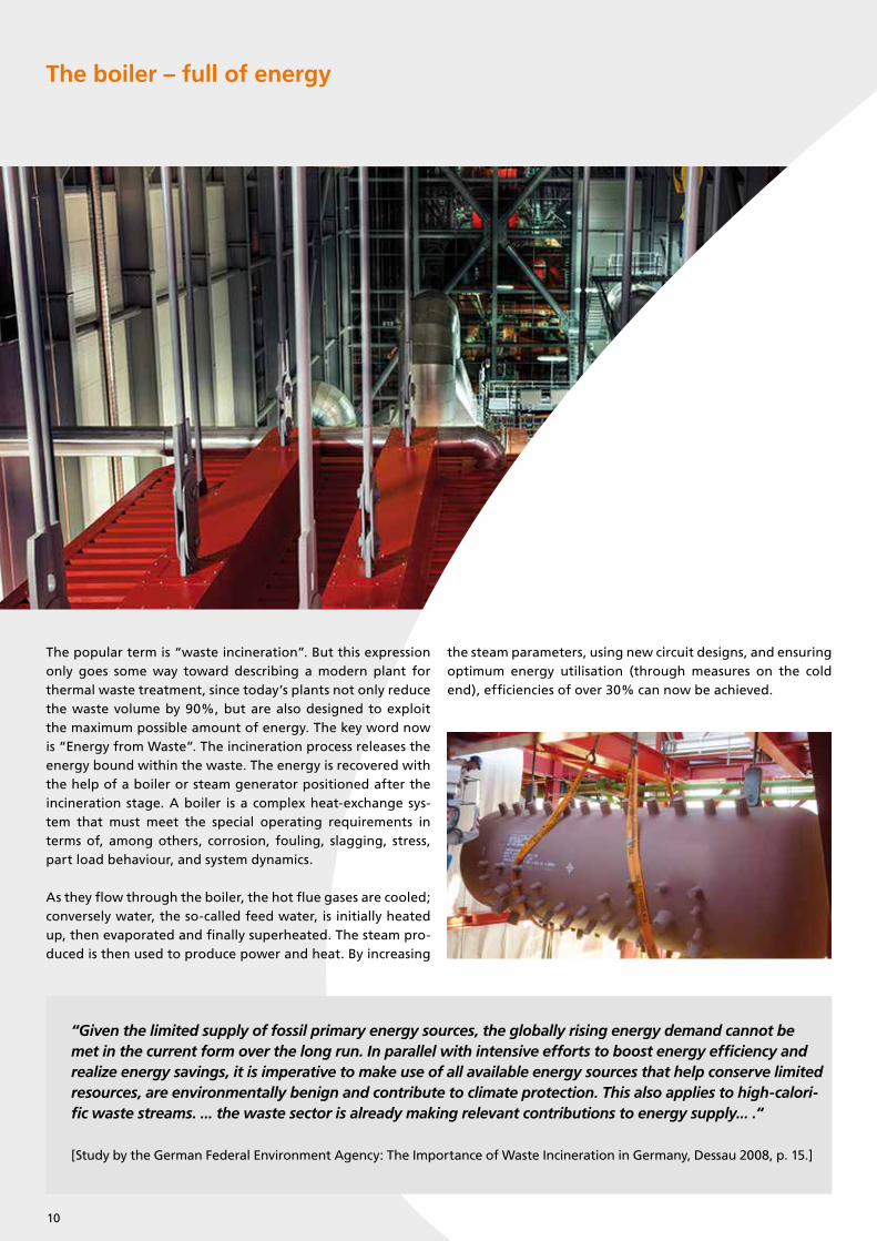
The boiler – full of energy
The popular term is “waste incineration”. But this expression only goes some way toward describing a modern plant for thermal waste treatment, since today’s plants not only reduce the waste volume by 90%, but are also designed to exploit the maximum possible amount of energy. The key word now is “Energy from Waste”. The incineration process releases the energy bound within the waste. The energy is recovered with the help of a boiler or steam generator positioned after the incineration stage. A boiler is a complex heat-exchange sys-tem that must meet the special operating requirements in terms of, among others, corrosion, fouling, slagging, stress, part load behaviour, and system dynamics.
As they flow through the boiler, the hot flue gases are cooled; conversely water, the so-called feed water, is initially heated up, then evaporated and finally superheated. The steam pro-duced is then used to produce power and heat. By increasing
the steam parameters, using new circuit designs, and ensuring optimum energy utilisation (through measures on the cold end), efficiencies of over 30% can now be achieved.
“Given the limited supply of fossil primary energy sources, the globally rising energy demand cannot be met in the current form over the long run. In parallel with intensive efforts to boost energy efficiency and realize energy savings, it is imperative to make use of all available energy sources that help conserve limited resources, are environmentally benign and contribute to climate protection. This also applies to high-calori-fic waste streams. ... the waste sector is already making relevant contributions to energy supply... .“
[Study by the German Federal Environment Agency: The Importance of Waste Incineration in Germany, Dessau 2008, p. 15.]
10

Quality guarantees long service life
Steinmüller Babcock Environment designs and builds tailored systems, adapted to the predicted calorific value of the waste. Our boiler systems are adapted to the respective operating conditions, right down to the finest details. As well as the ma-terials concept, which guarantees a long boiler service life, the boiler‘s time between services is also a decisive quality aspect.
In our systems the sequence, layout, and construction, as well as the protection of the heating surfaces, all take special ac-count of risk factors including fouling, slagging, corrosion, and erosion.
And during the system‘s operation, our After Sales Service is on-hand to carry out checks as part of inspections and to de-velop any measures needed to ensure trouble-free and effi-cient operation.
11
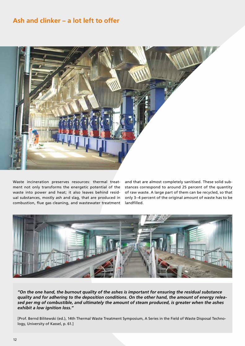
Ash and clinker – a lot left to offer
Waste incineration preserves resources: thermal treat-ment not only transforms the energetic potential of the waste into power and heat; it also leaves behind resid- ual substances, mostly ash and slag, that are produced in combustion, flue gas cleaning, and wastewater treatment
and that are almost completely sanitised. These solid sub-stances correspond to around 25 percent of the quantity of raw waste. A large part of them can be recycled, so that only 3–4 percent of the original amount of waste has to be landfilled.
“On the one hand, the burnout quality of the ashes is important for ensuring the residual substance quality and for adhering to the deposition conditions. On the other hand, the amount of energy relea-sed per mg of combustible, and ultimately the amount of steam produced, is greater when the ashes exhibit a low ignition loss.“
[Prof. Bernd Bilitewski (ed.), 14th Thermal Waste Treatment Symposium, A Series in the Field of Waste Disposal Techno-logy, University of Kassel, p. 61.]
12
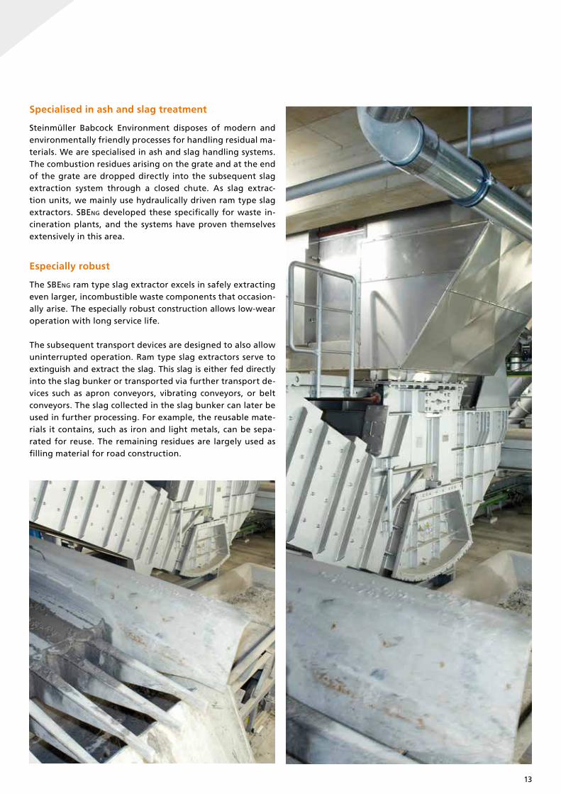
Specialised in ash and slag treatment
Steinmüller Babcock Environment disposes of modern and environmentally friendly processes for handling residual ma-terials. We are specialised in ash and slag handling systems. The combustion residues arising on the grate and at the end of the grate are dropped directly into the subsequent slag extraction system through a closed chute. As slag extrac- tion units, we mainly use hydraulically driven ram type slag extractors. SBEng developed these specifically for waste in-cineration plants, and the systems have proven themselves extensively in this area.
Especially robust
The SBEng ram type slag extractor excels in safely extracting even larger, incombustible waste components that occasion- ally arise. The especially robust construction allows low-wear operation with long service life.
The subsequent transport devices are designed to also allow uninterrupted operation. Ram type slag extractors serve to extinguish and extract the slag. This slag is either fed directly into the slag bunker or transported via further transport de-vices such as apron conveyors, vibrating conveyors, or belt conveyors. The slag collected in the slag bunker can later be used in further processing. For example, the reusable mate-rials it contains, such as iron and light metals, can be sepa-rated for reuse. The remaining residues are largely used as filling material for road construction.
13
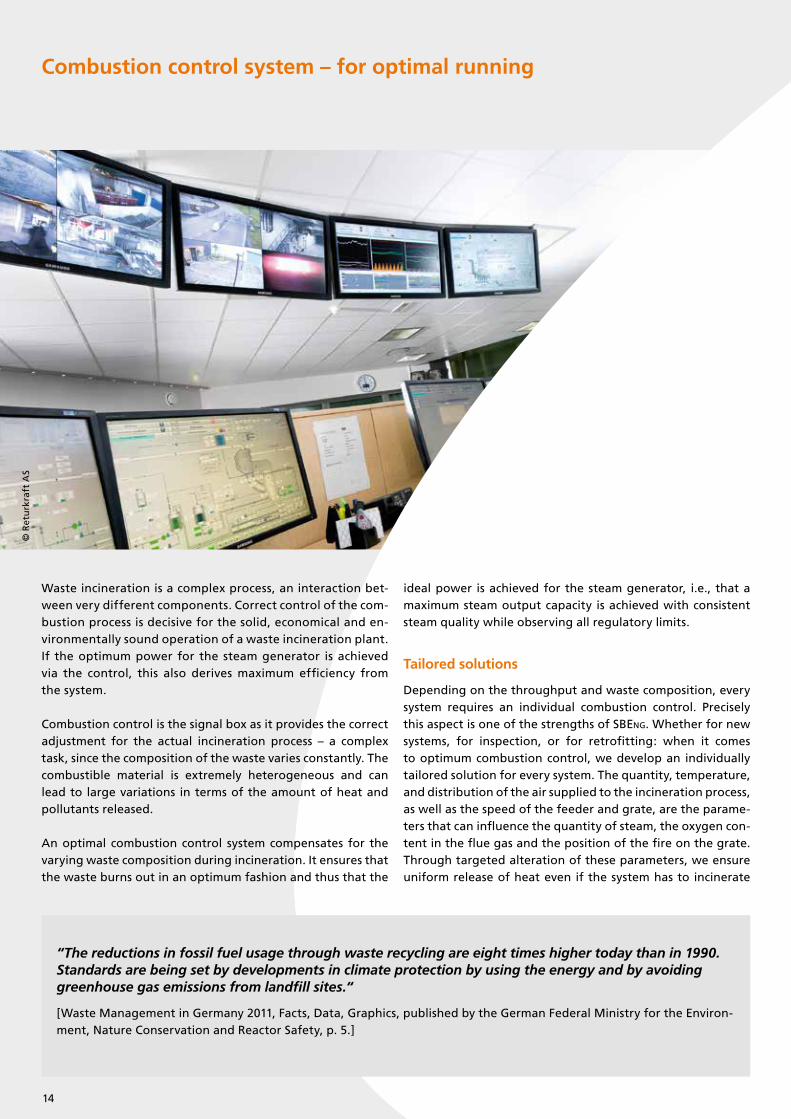
Combustion control system – for optimal running
Waste incineration is a complex process, an interaction bet-ween very different components. Correct control of the com-bustion process is decisive for the solid, economical and en-vironmentally sound operation of a waste incineration plant. If the optimum power for the steam generator is achieved via the control, this also derives maximum efficiency from the system.
Combustion control is the signal box as it provides the correct adjustment for the actual incineration process – a complex task, since the composition of the waste varies constantly. The combustible material is extremely heterogeneous and can lead to large variations in terms of the amount of heat and pollutants released.
An optimal combustion control system compensates for the varying waste composition during incineration. It ensures that the waste burns out in an optimum fashion and thus that the
ideal power is achieved for the steam generator, i.e., that a maximum steam output capacity is achieved with consistent steam quality while observing all regulatory limits.
Tailored solutions
Depending on the throughput and waste composition, every system requires an individual combustion control. Precisely this aspect is one of the strengths of SBEng. Whether for new systems, for inspection, or for retrofitting: when it comes to optimum combustion control, we develop an individually tailored solution for every system. The quantity, temperature, and distribution of the air supplied to the incineration process, as well as the speed of the feeder and grate, are the parame-ters that can influence the quantity of steam, the oxygen con-tent in the flue gas and the position of the fire on the grate. Through targeted alteration of these parameters, we ensure uniform release of heat even if the system has to incinerate
“The reductions in fossil fuel usage through waste recycling are eight times higher today than in 1990.Standards are being set by developments in climate protection by using the energy and by avoiding greenhouse gas emissions from landfill sites.“
[Waste Management in Germany 2011, Facts, Data, Graphics, published by the German Federal Ministry for the Environ-ment, Nature Conservation and Reactor Safety, p. 5.]
© R
etu
rkra
ft A
S
14
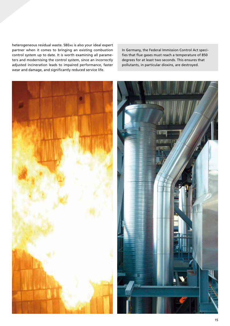
heterogeneous residual waste. SBEng is also your ideal expert partner when it comes to bringing an existing combustion control system up to date. It is worth examining all parame-ters and modernising the control system, since an incorrectly adjusted incineration leads to impaired performance, faster wear and damage, and significantly reduced service life.
In Germany, the Federal Immission Control Act speci-fies that flue gases must reach a temperature of 850 degrees for at least two seconds. This ensures that pollutants, in particular dioxins, are destroyed.
15
Hazardous waste – the end of the line for dangerous refuse
Hazardous waste is a legal term for which the European Un-ion‘s list of refuse includes around 400 types of waste. These include, among others:
• Residues from production processes in the chemicals industry• Laboratory chemicals• Used pesticides• Hospital waste, infectious materials• Highly polluted industrial waste
This hazardous waste may not be incinerated together with normal household and residual waste. It belongs in systems that allow high-temperature incineration. This is because in the thermal treatment of hazardous waste a temperature of 1100 degrees must be reached for at least two seconds in or-der to prevent the release of emissions that are harmful to health and to the environment. The high temperatures ensure the destruction of all organic substances. Furthermore, this type of waste treatment makes it possible to obtain energy in
the form of steam and power from polluted, contaminated, and mixed waste. This technology therefore currently repre-sents the only proven procedure for the economically sound treatment of large quantities of hazardous waste.
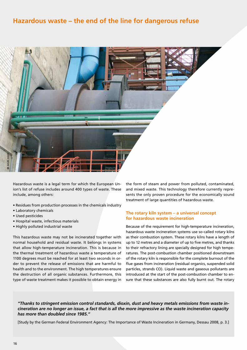
The rotary kiln system – a universal conceptfor hazardous waste incineration
Because of the requirement for high-temperature incineration, hazardous waste incineration systems use so-called rotary kilns as their combustion system. These rotary kilns have a length of up to 12 metres and a diameter of up to five metres, and thanks to their refractory lining are specially designed for high tempe-ratures. The post-combustion chamber positioned downstream of the rotary kiln is responsible for the complete burnout of the flue gases from incineration (residual organics, suspended solid particles, strands CO). Liquid waste and gaseous pollutants are introduced at the start of the post-combustion chamber to en-sure that these substances are also fully burnt out. The rotary
“Thanks to stringent emission control standards, dioxin, dust and heavy metals emissions from waste in-cineration are no longer an issue, a fact that is all the more impressive as the waste incineration capacity has more than doubled since 1985.“
[Study by the German Federal Environment Agency: The Importance of Waste Incineration in Germany, Dessau 2008, p. 3.]
© A
GR
mb
H
16

© A
GR
mb
H
© A
GR
mb
H
kiln and post-combustion chamber can therefore be seen as an integral system of two-stage incineration, which also allows the treatment of hazardous waste with a highly variable consistency.
Systems for hazardous waste incineration can be used to incin-erate coarse solids, drummed and barreled waste, paste-like, liquid and gaseous waste. Such a system consists of waste stor-age, a feeding chute for all types of waste and drummed waste, a rotary kiln, a post-combustion chamber, a heat-recovery steam generator, and a flue gas cleaning. Flexibility of opera- tion in terms of the waste feed allows the system to adapt to variations in the amount and composition of waste over time.
Built according to individual requirements
SBEng plans, builds and manages ready-to-use hazardous waste incineration plants. These plants are configured according to individual requirements. We guarantee highly developed technology that has proven itself in renowned companies in the chemical industry. Our thermal treatment exploits the energetic potential of hazardous waste to obtain steam, pow-er, and heat. At the same time it guarantees the safe and environmentally sound disposal of hazardous substances and, thanks to advanced flue gas cleaning, ensures that emission values lie significantly below the maximum permitted limits.
17

Flue Gas Cleaning – for pure air
Waste is not a simple matter. Waste composition is hetero- geneous and leads to the formation of flue gases with varying content of pollutants. If these are left unfiltered, they will cause significant air pollution. However, the modern thermal treat-ment process poses no risk to the environment.
Harmful substances such as dioxins, particulate matter, or heavy metals have long since been absent from the emissions of waste incineration processes. The air in the area surrounding the plants is proven to be clean. This is thanks to modern flue gas cleaning systems. Thermal waste incineration is subject to the strictest re-gulations of permitted emissions in comparison to other indus-trial processes in Germany and Europe. Thereby they produce emissions, which are often cleaner than the combustion air.
Products of leading-edge technology
Steinmüller Babcock Environment feels a particular sense of duty to the environment. Thus, our flue gas cleaning sys-
tems use cutting-edge technology developed on the basis of decades of research and practical experience. We know the problem well: only if the pollutants in flue gases are safely removed, the strictest emission requirements can be met as a result and waste incineration plants enjoy the necessary acceptance by society.
Maximum flexibility
Our different technologies of flue gas cleaning and flue gas desulfurization can fulfill the strict emission regula-tions even with high pollutant contents. SBEng possesses a broad technological portfolio, from which the most suit- able technologies can be chosen and combined, in order to meet each combustible’s and each customer’s underlying conditions and requirements. With decades of experiences with the construction of flue gas cleaning plants, Steinmül-ler Babcock Environment has convincing reference projects that show the effectivity and reliability of its plants.
“... without waste incinerators, ambient air pollutant levels would be much higher than with waste incine-rators. After all, electricity and heat generated in MSWIs substitute fossil energy sources in conventional (heat and) power plants which typically release higher specific pollutant levels than waste incinerators.“
[Study by the German Federal Environment Agency: The Importance of Waste Incineration in Germany, Dessau 2008, p. 4.]
18

Energy from flue gas
Our systems are designed for energy efficiency. Depending on the wishes of the respective customer, the flue gas cleaning can be combined with energy recovery systems e.g., by flue gas con-densation. This leads to an increase in the overall efficiency. De-
Core technologies of our Flue Gas Cleaning
Dedusting• Fabric filter• Electrostatic precipitator• Wet electrostatic precipitator
Separation of acidic gaseous pollutants• Combined scrubbing systems based on lime products or sodium hydroxide• Spray absorption with lime milk• Conditioned dry scrubbing with slaked lime (CIRCUSORB®)• Dry scrubbing with sodium bicarbonate• Combined scrubbing processes
(X) moderate deposition as side effect | X1 if alkaline sorbents are added | X² if activated carbon or lignite coke sorbents are added
Dust X X (X) X (X)
HCI X X X X1 X X
HF X X X X1 X X
SO2 X X X X1 X X
SO3 X X X X1 X X X
Droplet and aerosols X X
Quicksilver / Hg X2 X2 X2 X2 (X) X
Other heavy metals (X) X2 X2 X2 X2 (X) (X) X
NOX X X
Dioxins, furans and aromatic hydrocarbons X2 X2 X2 X2 X X
Technologies for removal of
different pollutants
SNCR
Elec
trost
atic
precip
itato
r
Dry-
Conditioned
-dry
-
(Circ
usorb
®)
Sem
i-dry
-
Bag fi
lter
Combin
ed sc
rubber
syst
ems
Wet
ele
ctro
stat
ic pre
cipita
tor
Lignite
Coke
Fixe
d Bed
Abso
rber
SCR C
atal
yst
Removal of heavy metals and organic compounds• Injection of activated carbon• Activated carbon fixed-bed adsorber• Catalytic dioxin removal
Denitrification• SCR process for catalytic reduction in NOx emissions, as both “High Dust“ and “Low Dust“ configurations• SNCR process for non-catalytic reduction in NOx emissions using ammonia or urea solutions
Energy-recovery systems• Downstream economiser• Heat transfer systems for preheating of combustion air• Flue gas condensation, e.g., for district heating use (optionally with heat pump)• Heat transfer systems within the flue gas cleaning for optimising energy efficiency
livering constant improvement in this respect is one of the big technical challenges facing thermal waste treatment. With our technologies, we have access to optimum solutions for increa-sing the energy output.
Sorption
19
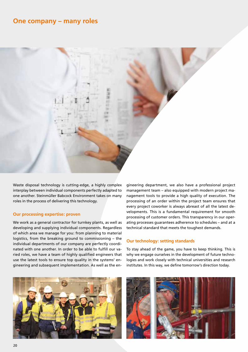
One company – many roles
Waste disposal technology is cutting-edge, a highly complex interplay between individual components perfectly adapted to one another. Steinmüller Babcock Environment takes on many roles in the process of delivering this technology.
Our processing expertise: proven
We work as a general contractor for turnkey plants, as well as developing and supplying individual components. Regardless of which area we manage for you: from planning to material logistics, from the breaking ground to commissioning – the individual departments of our company are perfectly coordi-nated with one another. In order to be able to fulfill our va-ried roles, we have a team of highly qualified engineers that use the latest tools to ensure top quality in the systems‘ en-gineering and subsequent implementation. As well as the en-
gineering department, we also have a professional project management team – also equipped with modern project ma-nagement tools to provide a high quality of execution. The processing of an order within the project team ensures that every project coworker is always abreast of all the latest de-velopments. This is a fundamental requirement for smooth processing of customer orders. This transparency in our oper- ating processes guarantees adherence to schedules – and at a technical standard that meets the toughest demands.
Our technology: setting standards
To stay ahead of the game, you have to keep thinking. This is why we engage ourselves in the development of future techno-logies and work closely with technical universities and research institutes. In this way, we define tomorrow’s direction today.
20
Our head start: many years of experience
Whether as a supplier of the entire process chain or of indivi-dual components – we use our long experience to constantly optimise our products and processes for longterm, efficient, economically sound use.
Especially important to us: safety and quality
Quality and safety have top priority for us. This is why we are certified in terms of our management systems for health, safety and environmental protection. We are not only sup-plier of boiler systems, but also certified as a manufacturer according to current EU guidelines. With the corresponding ASME S stamp (construction) and ASME R stamp (repairs, reconstructions) we have also created a basis for selling our products in the U.S.A., Canada, and 90 other countries. With these in place, there are no limits to the use of our products. Also in the long term we ensure the outstanding quality of our products. That’s why we maintain our own welding and testing procedure, which is appointed with certified procedure qualifications according to EN ISO 15614 and EN 473.
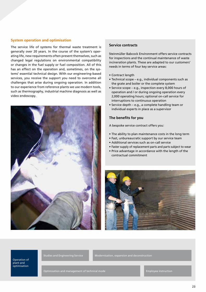
Our performance profile:
• General contractor for turnkey plants and single lots
• Supplier of key components
• After Sales Service
• Engineering provider
This certification was conducted in accordance with the TÜV NORD CERT auditing and certification procedures and is subject to
regular surveillance audits.
TÜV NORD CERT GmbH 45141 EssenLangemarckstraße 20 www.tuev-nord-cert.com
Management system as per
DIN EN ISO 14001 : 2009
In accordance with TÜV NORD CERT procedures, it is hereby certified that
C E R T I F I C A T E
Essen, 2014-08-29Certification Body
at TÜV NORD CERT GmbH
applies a management system in line with the above standard for the following scope
Plants, Components and Systems for Power- and Environmental-Technology,Design, Engineering, Erection, Commissioning and Service
Certificate Registration No. 44 104 066261
Audit Report No. 3513 2662
Valid from 2014-05-17
Valid until 2017-05-16
Steinmüller Babcock Environment GmbHFabrikstraße 151643 GummersbachGermany
Initial certification 2011
21

Our After Sales Service – always at your side
Even after completion and commissioning of the system, we are there for our customers. With us you have access to all services, from engineering to assembly, and from inspection to repairs of all components: a fully featured, one-stop service team, com-prehensive, versatile, and reliable to ensure minimum downtime and maximum efficiency for your plant. Along the complete pro-cess chain our After Sales Service is the competent partner at your side – not only for plants constructed by us.
As part of a plant manufacturer, our After Sales Service disposes of the entire knowledge of our development, engineering and construction departments. Our comprehensive know-how is at your disposal for studies, optimisation of plant concepts, the mo-dernisation of plants and also forms the basis for maintenance work at the highest quality level. As an authorised manufacturer of pressure equipment, Steinmüller Babcock Environment is in possession of all certificates required for offering the enginee-ring, manufacturing, delivery, assembly, and documentation of
pressure parts. As a result of our in-house procedure qualificati-on records (PQRs) and welding procedure specifications (WPSs), we meet the legal requirements of the Pressure Equipment Di-rective (97/23/EC) and are therefore able to market certified sys-tems.
Inspection, maintenance, and repairs
Prevention is better than downtime. Planned services are the cornerstone of an economically sound maintenance strategy. Our After Sales Service advises you on preventive measures and offers both individual and all-round inspection services. In this way shutdown periods are shortened and the availabil- ity of the plant increases. The organisation and execution of maintenance work is based on the time frame you specify and is tailored to the needs of your system. Our experienced per-sonnel know how to reconcile scheduling requirements with the necessary scope of measures.
Inspection,maintenance,and repairs
Revision and maintenance Inspection and repairSpare- and wear parts management
Service contracts for wear partsService contracts(incl. on-call service/operational management)
Our range of services
22
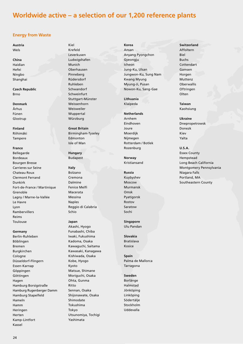
System operation and optimisation
The service life of systems for thermal waste treatment is generally over 20 years. In the course of the system’s oper- ating life, new requirements often present themselves, such as changed legal regulations on environmental compatibility or changes in the fuel supply or fuel composition. All of this has an effect on the operation and, sometimes, on the sys-tems’ essential technical design. With our engineering-based services, you receive the support you need to overcome all challenges that arise during ongoing operation. In addition to our experience from reference plants we use modern tools, such as thermography, industrial machine diagnosis as well as video endoscopy.
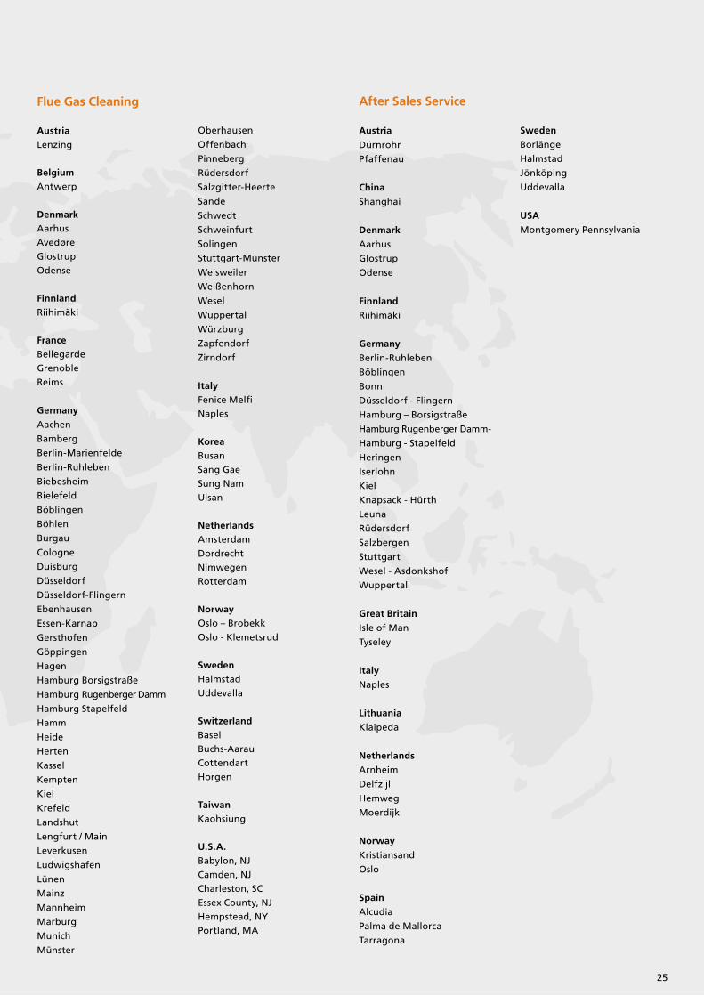
Service contracts
Steinmüller Babcock Environment offers service contracts for inspections and the continual maintenance of wasteincineration plants. These are adapted to our customers‘needs in terms of four key service areas:
• Contract length• Technical scope – e.g., individual components such as the grate and boiler or the complete system• Service scope – e.g., inspection every 8,000 hours of operation and / or during ongoing operation every 2,000 operating hours; optional on-call service for interruptions to continuous operation• Service depth – e.g., a complete handling team or individual experts in place as a supervisor
The benefits for you
A bespoke service contract offers you:
• The ability to plan maintenance costs in the long term• Fast, unbureaucratic support by our service team• Additional services such as on-call service• Faster supply of replacement parts and parts subject to wear• Price advantage in accordance with the length of the contractual commitment
Operation of plant andoptimisation
Employee instruction
Studies and Engineering Service
Optimisation and management of technical mode
Modernisation, expansion and deconstruction
23
Energy from Waste
Austria
Wels
China
Haidian
Hefei
Ningbo
Shanghai
Czech Republic
Brno
Denmark
Århus
Fünen
Glostrup
Finland
Riihimäki
Tampere
France
Bellegarde
Bordeaux
Bourgen Bresse
Carrieres sur Seine
Chateau Roux
Clermont Ferrand
Dunkirk
Fort-de-France / Martinique
Grenoble
Lagny / Marne-la-Vallée
Le Havre
Lyon
Rambervillers
Reims
Toulouse
Germany
Berlin-Ruhleben
Böblingen
Bremen
Burgkirchen
Cologne
Düsseldorf-Flingern
Essen-Karnap
Göppingen
Göttingen
Hagen
Hamburg Borsigstraße
Hamburg Rugenberger Damm
Hamburg Stapelfeld
Hameln
Hamm
Heringen
Herten
Kamp-Lintfort
Kassel
Kiel
Krefeld
Leverkusen
Ludwigshafen
Munich
Oberhausen
Pinneberg
Rüdersdorf
Ruhleben
Schwandorf
Schweinfurt
Stuttgart-Münster
Weissenhorn
Weisweiler
Wuppertal
Würzburg
Great Britain
Birmingham-Tyseley
Edmonton
Isle of Man
Hungary
Budapest
Italy
Bolzano
Cremona
Dalmine
Fenice Melfi
Macerata
Messina
Naples
Reggio di Calabria
Schio
Japan
Akashi, Hyogo
Funabashi, Chiba
Iwaki, Fukushima
Kadoma, Osaka
Kawaguchi, Saitama
Kawasaki, Kanagawa
Kishiwada, Osaka
Kobe, Hyogo
Kyoto
Matsue, Shimane
Moriguchi, Osaka
Ohta, Gunma
Ritto
Sennan, Osaka
Shijonawate, Osaka
Shimodate
Tokushima
Tokyo
Utsunomiya, Tochigi
Yashimata
Korea
Ansan
Anyang Pyongchon
Gyeongju
Icheon
Jung-Ku, Ulsan
Jungwon-Ku, Sung Nam
Kwang Myung
Myung-Ji, Pusan
Nowon-Ku, Sang-Gae
Lithuania
Klaipeda
Netherlands
Arnhem
Eindhoven
Joure
Moerdijk
Nijmegen
Rotterdam / Botlek
Rozenburg
Norway
Kristiansand
Russia
Kuybyshev
Moscow
Murmansk
Omsk
Pyatigorsk
Rostov
Saratow
Sochi
Singapore
Ulu Pandan
Slovakia
Bratislava
Kosice
Spain
Palma de Mallorca
Tarragona
Sweden
Borlänge
Halmstad
Jönköping
Linköping
Södertälje
Stockholm
Uddevalla
Switzerland
Affoltern
Biel
Buchs
Cottendart
Gamsen
Horgen
Muttenz
Oberwallis
Oftringen
Olten
Taiwan
Kaohsiung
Ukraine
Dnepropetrowsk
Donezk
Kiev
Yalta
U.S.A.
Essex County
Hempstead
Long Beach California
Montgomery Pennsylvania
Niagara Falls
Portland, MA
Southeastern County
Worldwide active – a selection of our 1,200 reference plants
24
Flue Gas Cleaning
AustriaLenzing
BelgiumAntwerp
DenmarkAarhus
Avedøre
Glostrup
Odense
FinnlandRiihimäki
FranceBellegarde
Grenoble
Reims
Germany
Aachen
Bamberg
Berlin-Marienfelde
Berlin-Ruhleben
Biebesheim
Bielefeld
Böblingen
Böhlen
Burgau
Cologne
Duisburg
Düsseldorf
Düsseldorf-Flingern
Ebenhausen
Essen-Karnap
Gersthofen
Göppingen
Hagen
Hamburg Borsigstraße
Hamburg Rugenberger Damm
Hamburg Stapelfeld
Hamm
Heide
Herten
Kassel
Kempten
Kiel
Krefeld
Landshut
Lengfurt / Main
Leverkusen
Ludwigshafen
Lünen
Mainz
Mannheim
Marburg
Munich
Münster
Oberhausen
Offenbach
Pinneberg
Rüdersdorf
Salzgitter-Heerte
Sande
Schwedt
Schweinfurt
Solingen
Stuttgart-Münster
Weisweiler
Weißenhorn
Wesel
Wuppertal
Würzburg
Zapfendorf
Zirndorf
ItalyFenice Melfi
Naples
KoreaBusan
Sang Gae
Sung Nam
Ulsan
NetherlandsAmsterdam
Dordrecht
Nimwegen
Rotterdam
NorwayOslo – Brobekk
Oslo - Klemetsrud
SwedenHalmstad
Uddevalla
SwitzerlandBasel
Buchs-Aarau
Cottendart
Horgen
TaiwanKaohsiung
U.S.A.Babylon, NJ
Camden, NJ
Charleston, SC
Essex County, NJ
Hempstead, NY
Portland, MA
After Sales Service
Austria
Dürnrohr
Pfaffenau
China
Shanghai
Denmark
Aarhus
Glostrup
Odense
Finnland
Riihimäki
Germany
Berlin-Ruhleben
Böblingen
Bonn
Düsseldorf - Flingern
Hamburg – Borsigstraße
Hamburg Rugenberger Damm-
Hamburg - Stapelfeld
Heringen
Iserlohn
Kiel
Knapsack - Hürth
Leuna
Rüdersdorf
Salzbergen
Stuttgart
Wesel - Asdonkshof
Wuppertal
Great Britain
Isle of Man
Tyseley
Italy
Naples
Lithuania
Klaipeda
Netherlands
Arnheim
Delfzijl
Hemweg
Moerdijk
Norway
Kristiansand
Oslo
Spain
Alcudia
Palma de Mallorca
Tarragona
Sweden
Borlänge
Halmstad
Jönköping
Uddevalla
USA
Montgomery Pennsylvania
25
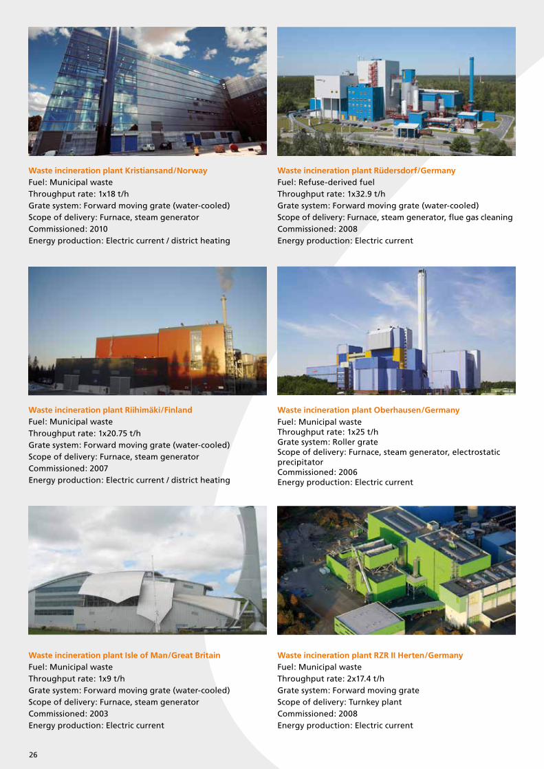
Waste incineration plant Kristiansand/NorwayFuel: Municipal wasteThroughput rate: 1x18 t/hGrate system: Forward moving grate (water-cooled)Scope of delivery: Furnace, steam generatorCommissioned: 2010Energy production: Electric current / district heating
Waste incineration plant Rüdersdorf/GermanyFuel: Refuse-derived fuelThroughput rate: 1x32.9 t/hGrate system: Forward moving grate (water-cooled)Scope of delivery: Furnace, steam generator, flue gas cleaningCommissioned: 2008Energy production: Electric current
Waste incineration plant Oberhausen/GermanyFuel: Municipal wasteThroughput rate: 1x25 t/hGrate system: Roller grateScope of delivery: Furnace, steam generator, electrostatic precipitatorCommissioned: 2006Energy production: Electric current
Waste incineration plant Isle of Man/Great BritainFuel: Municipal wasteThroughput rate: 1x9 t/hGrate system: Forward moving grate (water-cooled)Scope of delivery: Furnace, steam generatorCommissioned: 2003Energy production: Electric current
Waste incineration plant RZR II Herten/GermanyFuel: Municipal wasteThroughput rate: 2x17.4 t/hGrate system: Forward moving grateScope of delivery: Turnkey plantCommissioned: 2008Energy production: Electric current
Waste incineration plant Riihimäki/FinlandFuel: Municipal wasteThroughput rate: 1x20.75 t/hGrate system: Forward moving grate (water-cooled)Scope of delivery: Furnace, steam generatorCommissioned: 2007Energy production: Electric current / district heating
26
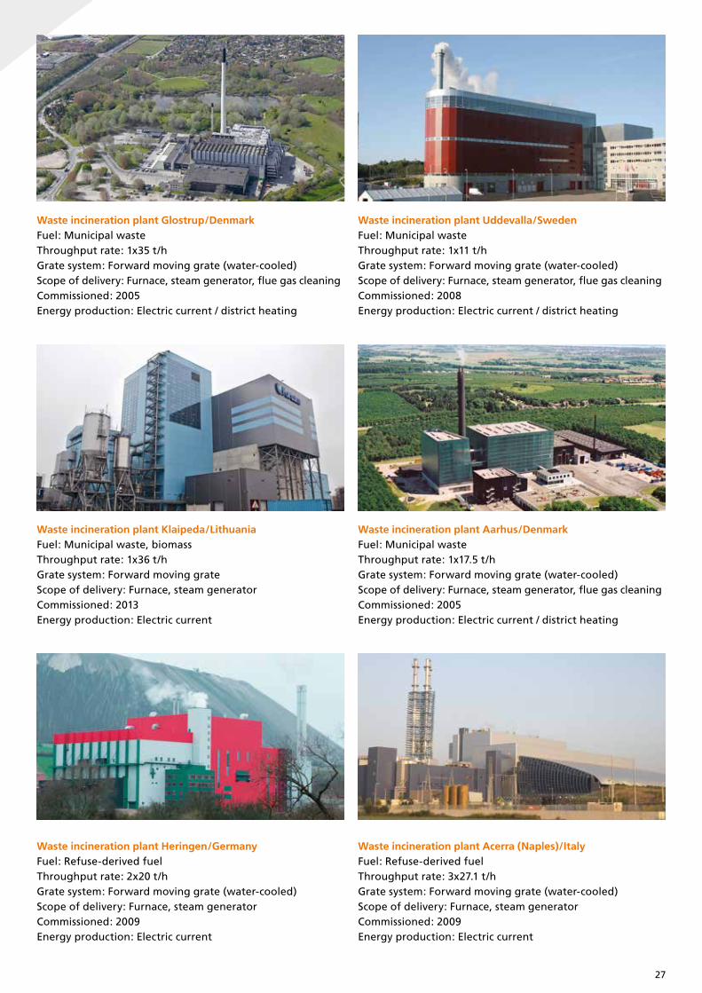
Waste incineration plant Acerra (Naples)/ItalyFuel: Refuse-derived fuelThroughput rate: 3x27.1 t/hGrate system: Forward moving grate (water-cooled)Scope of delivery: Furnace, steam generatorCommissioned: 2009Energy production: Electric current
Waste incineration plant Glostrup/DenmarkFuel: Municipal wasteThroughput rate: 1x35 t/hGrate system: Forward moving grate (water-cooled)Scope of delivery: Furnace, steam generator, flue gas cleaningCommissioned: 2005Energy production: Electric current / district heating
Waste incineration plant Uddevalla/SwedenFuel: Municipal wasteThroughput rate: 1x11 t/hGrate system: Forward moving grate (water-cooled)Scope of delivery: Furnace, steam generator, flue gas cleaningCommissioned: 2008Energy production: Electric current / district heating
Waste incineration plant Klaipeda/LithuaniaFuel: Municipal waste, biomassThroughput rate: 1x36 t/hGrate system: Forward moving grate Scope of delivery: Furnace, steam generatorCommissioned: 2013Energy production: Electric current
Waste incineration plant Aarhus/DenmarkFuel: Municipal wasteThroughput rate: 1x17.5 t/hGrate system: Forward moving grate (water-cooled)Scope of delivery: Furnace, steam generator, flue gas cleaningCommissioned: 2005Energy production: Electric current / district heating
Waste incineration plant Heringen/GermanyFuel: Refuse-derived fuelThroughput rate: 2x20 t/hGrate system: Forward moving grate (water-cooled)Scope of delivery: Furnace, steam generatorCommissioned: 2009Energy production: Electric current
27

Steinmüller Babcock
Environment GmbH
Fabrikstraße 1
51643 Gummersbach / Germany
Phone: +49 (0) 2261 85-0
Fax: +49 (0) 2261 85-3309
www.steinmueller-babcock.com
Top Related