


Languages
Pages
Legal

EMV ‘96Integrated Circuit CardSpecification for Payment Systems
Version 3.1.1May 31, 1998
© 1998 Europay International S.A., MasterCard International Incorporated, and Visa International ServiceAssociation. All rights reserved. Permission to copy and implement the material contained herein isgranted subject to the conditions that (i) any copy or re-publication must bear this legend in full, (ii) anyderivative work must bear a notice that it is not the Integrated Circuit Card Specification for PaymentSystems jointly published by the copyright holders, and (iii) that none of the copyright holders shall haveany responsibility or liability whatsoever to any other party arising from the use or publication of thematerial contained herein.
The authors of this documentation make no representation or warranty regarding whether any particularphysical implementation of any part of this Specification does or does not violate, infringe, or otherwiseuse the patents, copyrights, trademarks, trade secrets, know-how, and/or other intellectual property of thirdparties, and thus any person who implements any part of this Specification should consult an intellectualproperty attorney before any such implementation. The following Specification includes public keyencryption technology, which is the subject matter of patents in several countries. Any party seeking toimplement this Specification is solely responsible for determining whether their activities require a licenseto any technology including, but not limited to, patents on public key encryption technology. EuropayInternational S. A., MasterCard International Incorporated, and Visa International Service Association shallnot be liable for any party’s infringement of any intellectual property right.

May 31, 1998 Contents i
Table of Contents
1. Scope ix1.1 EMV Specification Version Numbering x
2. Normative References xi3. Definitions xiv4. Abbreviations and Notations xviii
Part I - Electromechanical Characteristics, Logical Interface, andTransmission Protocols1. Electromechanical Interface I-1
1.1 Mechanical Characteristics of the ICC I-11.1.1 Physical Characteristics I-11.1.2 Dimensions and Location of Contacts I-11.1.3 Contact Assignment I-2
1.2 Electrical Characteristics of the ICC I-31.2.1 Measurement Conventions I-31.2.2 Input/Output (I/O) I-31.2.3 Programming Voltage (VPP) I-41.2.4 Clock (CLK) I-41.2.5 Reset (RST) I-51.2.6 Supply Voltage (VCC) I-51.2.7 Contact Resistance I-5
1.3 Mechanical Characteristics of the Terminal I-61.3.1 Interface Device I-61.3.2 Contact Forces I-71.3.3 Contact Assignment I-7
1.4 Electrical Characteristics of the Terminal I-71.4.1 Measurement Conventions I-71.4.2 Input/Output (I/O) I-71.4.3 Programming Voltage (VPP) I-91.4.4 Clock (CLK) I-91.4.5 Reset (RST) I-91.4.6 Supply Voltage (VCC) I-101.4.7 Contact Resistance I-101.4.8 Short Circuit Resilience I-101.4.9 Powering and Depowering of Terminal with ICC in Place I-10
2. Card Session I-112.1 Normal Card Session I-11
2.1.1 Stages of a Card Session I-112.1.2 ICC Insertion and Contact Activation Sequence I-112.1.3 ICC Reset I-122.1.4 Execution of a Transaction I-142.1.5 Contact Deactivation Sequence I-14
2.2 Abnormal Termination of Transaction Process I-153. Physical Transportation of Characters I-16
3.1 Bit Duration I-163.2 Character Frame I-16

ii Contents May 31, 1998
4. Answer to Reset I-184.1 Physical Transportation of Characters Returned at Answer to Reset I-184.2 Characters Returned by ICC at Answer to Reset I-184.3 Character Definitions I-20
4.3.1 TS - Initial Character I-214.3.2 T0 - Format Character I-224.3.3 TA1 to TC3 - Interface Characters I-224.3.4 TCK - Check Character I-28
4.4 Terminal Behaviour during Answer to Reset I-294.5 Answer to Reset - Flow at the Terminal I-30
5. Transmission Protocols I-315.1 Physical Layer I-315.2 Data Link Layer I-32
5.2.1 Character Frame I-325.2.2 Character Protocol T=0 I-325.2.3 Error Detection and Correction for T=0 I-345.2.4 Block Protocol T=1 I-355.2.5 Error Detection and Correction for T=1 I-42
5.3 Terminal Transport Layer (TTL) I-445.3.1 Transport of APDUs by T=0 I-445.3.2 Transportation of APDUs by T=1 I-51
5.4 Application Layer I-515.4.1 C-APDU I-52
5.4.2 R-APDU I-53
Part II - Data Elements and Commands1. Data Elements and Files II-1
1.1 Data Elements Associated with Financial Transaction Interchange II-11.2 Data Objects II-1
1.2.1 Classes of Data Objects II-21.3 Files II-2
1.3.1 File Structure II-21.3.2 File Referencing II-4
1.4 Rules for Using a Data Object List (DOL) II-42. Commands for Financial Transaction II-6
2.1 Message Structure II-62.1.1 Command APDU Format II-62.1.2 Response APDU Format II-72.1.3 Command-Response APDU Conventions II-8
2.2 Coding Conventions II-82.2.1 Coding of the Class Byte II-82.2.2 Coding of the Instruction Byte II-82.2.3 Coding of Parameter Bytes II-92.2.4 Coding of Data Field Bytes II-92.2.5 Coding of the Status Bytes II-92.2.6 Coding of RFU Data II-12
2.3 Logical Channels II-132.4 Commands II-13
2.4.1 APPLICATION BLOCK Command-Response APDUs II-13

May 31, 1998 Contents iii
2.4.2 APPLICATION UNBLOCK Command-Response APDUs II-142.4.3 CARD BLOCK Command-Response APDUs II-152.4.4 EXTERNAL AUTHENTICATE Command-Response APDUs II-162.4.5 GENERATE APPLICATION CRYPTOGRAM Command-Response APDUs II-172.4.6 GET DATA Command-Response APDUs II-202.4.7 GET PROCESSING OPTIONS Command-Response APDUs II-212.4.8 INTERNAL AUTHENTICATE Command-Response APDUs II-222.4.9 PIN CHANGE/UNBLOCK Command-Response APDUs II-232.4.10 READ RECORD Command-Response APDUs II-252.4.11 SELECT Command-Response APDUs II-26
2.4.12 VERIFY Command-Response APDUs II-28
Part III - Application Selection1. Overview of Application Selection III-12. Data in the ICC Used for Application Selection III-2
2.1 Coding of Payment System Application Identifier III-22.2 Structure of the Payment Systems Environment III-22.3 Coding of a Payment System’s Directory III-32.4 Coding of Other Directories III-5
3. Building the Candidate List III-53.1 Matching Terminal Applications to ICC Applications III-53.2 Using the Payment Systems Directories III-63.3 Using a List of AIDs III-9
3.4 Final Selection III-11
Part IV - Security Aspects1. Static Data Authentication IV-1
1.1 Keys and Certificates IV-21.2 Retrieval of the Certification Authority Public Key IV-51.3 Retrieval of the Issuer Public Key IV-61.4 Verification of the Signed Static Application Data IV-7
2. Dynamic Data Authentication IV-92.1 Keys and Certificates IV-112.2 Retrieval of the Certification Authority Public Key IV-142.3 Retrieval of the Issuer Public Key IV-142.4 Retrieval of the ICC Public Key IV-162.5 Dynamic Signature Generation IV-182.6 Dynamic Signature Verification IV-19
3. Secure Messaging IV-213.1 Secure Messaging Format IV-213.2 Secure Messaging for Integrity and Authentication IV-21
3.2.1 Command Data Field IV-213.2.2 MAC Session Key Derivation IV-223.2.3 MAC Computation IV-22
3.3 Secure Messaging for Confidentiality IV-233.3.1 Command Data Field IV-233.3.2 Encipherment Session Key Derivation IV-233.3.3 Encipherment/Decipherment IV-23

iv Contents May 31, 1998
4. Personal Identification Number Encipherment IV-244.1 Keys and Certificates IV-24
4.2 PIN Encipherment and Verification IV-26
AnnexesAnnex A - Examples of Exchanges Using T=0 A-1
A1. Case 1 Command A-1A2. Case 2 Command A-1A3. Case 3 Command A-2A4. Case 4 Command A-2A5. Case 2 Commands Using the ‘61’ and ‘6C’ Procedure Bytes A-2A6. Case 4 Command Using the ‘61’ Procedure Byte A-3A7. Case 4 Command with Warning Condition A-3
Annex B - Data Elements Table B-1Annex C - Data Objects C-1
C1. Coding of BER-TLV Data Objects C-1Annex D - Examples of Directory Structures D-1
D1. Examples of Directory Structures D-1Annex E - Security Mechanisms E-1
E1. Symmetric Mechanisms E-1E2. Asymmetric Mechanisms E-4
Annex F - Approved Cryptographic Algorithms F-1F1. Symmetric Algorithms F-1F2. Asymmetric Algorithms F-1F3. Hashing Algorithms F-4
Annex G - Informative References G-1

May 31, 1998 Contents v
Tables
Table I-1 - ICC Contact Assignment I-3Table I-2 - Electrical Characteristics of I/O for ICC Reception I-4Table I-3 - Electrical Characteristics of I/O for ICC Transmission I-4Table I-4 - Electrical Characteristics of CLK to ICC I-4Table I-5 - Electrical Characteristics of RST to ICC I-5Table I-6 - IFD Contact Assignment I-7Table I-7 - Electrical Characteristics of I/O for Terminal Transmission I-8Table I-8 - Electrical Characteristics of I/O for Terminal Reception I-8Table I-9 - Electrical Characteristics of CLK from Terminal I-9Table I-10 - Electrical Characteristics of RST from Terminal I-9Table I-11 - Basic ATR for T=0 Only I-19Table I-12 - Basic ATR for T=1 Only I-20Table I-13 - Basic Response Coding of Character T0 I-22Table I-14 - Basic Response Coding of Character TB1 I-24Table I-15 - Basic Response Coding of Character TC1 I-25Table I-16 - Basic Response Coding of Character TD1 I-25Table I-17 - Basic Response Coding of Character TD2 I-27Table I-18 - Basic Response Coding of Character TA3 I-27Table I-19 - Basic Response Coding of Character TB3 I-28Table I-20 - Terminal Response to Procedure Byte I-33Table I-21 - Structure of a Block I-35Table I-22 - Coding of the PCB of an I-block I-36Table I-23 - Coding of the PCB of an R-block I-37Table I-24 - Coding of the PCB of a S-block I-37Table I-25 - Structure of Command Message I-50Table I-26 - GET RESPONSE Error Conditions I-51Table I-27 - Definition of Cases for Data in APDUs I-52Table I-28 - Cases of C-APDUs I-53Table II-1 - Structure of SFI II-4Table II-2 - Command APDU Content II-7Table II-3 - Response APDU Content II-7Table II-4 - Data Within an APDU Command-Response Pair II-8Table II-5 - Most Significant Nibble of the Class Byte II-8Table II-6 - Coding of the Instruction Byte II-9Table II-7 - Coding of Status Bytes SW1 SW2 II-10Table II-8 - Allocation of Status Bytes II-11Table II-9 - APPLICATION BLOCK Command Message II-14Table II-10 - APPLICATION UNBLOCK Command Message II-15Table II-11 - CARD BLOCK Command Message II-16Table II-12 - EXTERNAL AUTHENTICATE Command Message II-17Table II-13 - GENERATE AC Cryptogram Types II-18Table II-14 - GENERATE AC Command Message II-18Table II-15 - GENERATE AC Reference Control Parameter II-18Table II-16 - Format 1 GENERATE AC Response Message Data Field II-19Table II-17 - Coding of Cryptogram Information Data II-19Table II-18 - GET DATA Command Message II-20

vi Contents May 31, 1998
Table II-19 - GET PROCESSING OPTIONS Command Message II-21Table II-20 - Format 1 GET PROCESSING OPTIONS Response Message
Data Field II-22Table II-21 - INTERNAL AUTHENTICATE Command Message II-22Table II-22 - PIN CHANGE/UNBLOCK Command Message II-24Table II-23 - READ RECORD Command Message II-25Table II-24 - READ RECORD Command Reference Control Parameter II-25Table II-25 - READ RECORD Response Message Data Field II-25Table II-26 - SELECT Command Message II-26Table II-27 - SELECT Command Reference Control Parameter II-26Table II-28 - SELECT Command Options Parameter II-27Table II-29 - SELECT Response Message Data Field (FCI) of the PSE II-27Table II-30 - SELECT Response Message Data Field (FCI) of a DDF II-27Table II-31 - SELECT Response Message Data Field (FCI) of an ADF II-28Table II-32 - VERIFY Command Message II-29Table II-33 - VERIFY Command Qualifier of Reference Data (P2) II-29Table III-1 - PSE Directory Record Format III-4Table III-2 - DDF Directory Entry Format III-4Table III-3 - ADF Directory Entry Format III-4Table III-4 - Format of Application Priority Indicator IV-4Table IV-1 - Issuer Public Key Data to be Signed by the Certification
Authority IV-4Table IV-2 - Static Application Data to be Signed by the Issuer IV-5Table IV-3 - Data Objects Required for Static Data Authentication IV-5Table IV-4 - Format of the Data Recovered from the Issuer Public Key
Certificate IV-6Table IV-5 - Format of the Data Recovered from the Signed Static
Application Data IV-8Table IV-6 - Issuer Public Key Data to be Signed by the Certification
Authority IV-12Table IV-7 - ICC Public Key Data to be Signed by the Issuer IV-13Table IV-8 - Data Objects Required for Public Key Authentication for Dynamic
Authentication IV-14Table IV-9 - Format of the Data Recovered from the Issuer Public Key
Certificate IV-15Table IV-10 - Format of the Data Recovered from the ICC Public Key
Certificate IV-17Table IV-11 - Dynamic Application Data to be Signed IV-19Table IV-12 - Additional Data Objects Required for Dynamic Signature
Generation and Verification IV-19Table IV-13 - Format of the Data Recovered from the Signed Dynamic
Application Data IV-20Table IV-14 - ICC PIN Encipherment Public Key Data to be Signed
by the Issuer IV-25Table IV-15 - Data Objects Required for the Retrieval of the ICC PIN
Encipherment Public Key IV-26Table IV-16 - Data to be Enciphered for PIN Encipherment IV-27Table B-1 - Data Elements Dictionary B-11Table B-2 - Data Elements Tags B-15

May 31, 1998 Contents vii
Table C-1 - Tag Field Structure (First Byte) BER-TLV C-1Table C-2 - Tag Field Structure (Subsequent Bytes) BER-TLV C-2Table C-3 - Primitive BER-TLV Data Object (Data Element) C-3Table C-4 - Constructed BER-TLV Data Object C-3Table F-1 - Mandatory Upper Bound for the Size in Bytes of the Moduli F-1

viii Contents May 31, 1998
Figures
Figure I-2 - Layout of Contacts I-2Figure I-3 - Terminal Contact Location and Dimensions I-6Figure I-4 - Contact Activation Sequence I-12Figure I-5 - Cold Reset Sequence I-13Figure I-6 - Warm Reset Sequence I-14Figure I-7 - Contact Deactivation Sequence I-15Figure I-8 - Character Frame I-17Figure I-9 - ATR - Example Flow at the Terminal I-30Figure II-1 - Command APDU Structure II-6Figure II-2 - Response APDU Structure II-7Figure II-3 - Structural Scheme of Status Bytes II-10Figure III-1- Terminal Logic Using Directories III-8Figure III-2 - Using the List of Applications in the Terminal III-10Figure IV-1 - Diagram of Static Data Authentication IV-1Figure IV-2 - Diagram of Dynamic Data Authentication IV-9Figure IV-3 - Format 1 Command Data Field for Secure Messaging for
Integrity and Authentication IV-22Figure IV-4 - Format 2 Command Data Field for Secure Messaging for
Integrity and Authentication IV-22Figure IV-5 - Format 1 Enciphered Data Object in a Command Data Field IV-23Figure IV-6 - Format 2 Command Data Field for Secure Messaging for
Confidentiality IV-23Figure D-1 - Simplest Card Structure Single Application D-1Figure D-2 - Single Level Directory D-2Figure D-3 - Third Level Directory D-2

May 31, 1998 ICC Card Specification for Payment Systems ix
1. Scope
The Integrated Circuit Card (ICC) Specification for Payment Systems describes theminimum functionality required of integrated circuit cards (ICCs) and terminals toensure correct operation and interoperability. Additional proprietary functionalityand features may be provided, but these are beyond the scope of this specificationand interoperability cannot be guaranteed.
This specification consists of four parts:
Part I - Electromechanical Characteristics, Logical Interface, and Transmission Protocols
Part II - Data Elements and CommandsPart III - Application SelectionPart IV - Security Aspects
Part 1 defines electromechanical characteristics, logical interface, and transmissionprotocols as they apply to the exchange of information between an ICC and aterminal. In particular it covers:
• Mechanical characteristics, voltage levels, and signal parameters as they apply toboth ICCs and terminals.
• An overview of the card session. • Establishment of communication between the ICC and the terminal by means of
the answer to reset. • Character- and block-oriented asynchronous transmission protocols.
Part II defines data elements and commands as they apply to the exchange ofinformation between an ICC and a terminal. In particular it covers:
• Data elements for financial interchange and their mapping onto data objects. • Structure and referencing of files. • Structure and coding of messages between the ICC and the terminal to achieve
application level functions.
Part III defines the application selection process from the standpoint of both thecard and the terminal. The logical structure of data and files within the card that isrequired for the process is specified, as is the terminal logic using the card structure.
Part IV defines the security aspects of the processes specified in this specification.In particular it covers:
• Offline static data authentication.

x ICC Card Specification for Payment Systems May 31, 1998
• Offline dynamic data authentication.
• Offline PIN encipherment • Secure messaging.
This specification does not cover the details of Transaction Certificate generation bythe ICC, the internal implementation in the ICC, its security architecture, and itspersonalisation.
This specification is based on the ISO/IEC 7816 series of standards and should beread in conjunction with those standards. However, if any of the provisions ordefinitions in this specification differ from those standards, the provisions hereinshall take precedence.
This specification is intended for a target audience that includes manufacturers ofICCs and terminals, system designers in payment systems, and financial institutionstaff responsible for implementing financial applications in ICCs.
1.1 EMV Specification Version Numbering
To facilitate future reference of the EMV specifications and to differentiate betweentechnical updates and editorial clarifications, with the publication of this version ofthe EMV specifications, EMV has introduced the following version numberingscheme:
version X.Y.Z,
where:
X indicates the phase number of the specificationsY indicates technical change(s) from the previous versionZ indicates editorial change(s) from the previous version
Therefore, this version of the EMV specifications is version 3.1.1, since the basis forthis specification is version 3.0 and both technical and editorial changes have beenmade.
May 31, 1998 ICC Card Specification for Payment Systems xi
2. Normative References
The following standards contain provisions that are referenced in this specification.
Europay,MasterCard, andVisa (EMV): March31, 1998
Integrated Circuit Card Application Specification for PaymentSystems
Europay,MasterCard, andVisa (EMV): March31, 1998
Integrated Circuit Card Terminal Specification for PaymentSystems
FIPS Pub 180-1:1995 Secure Hash Standard
IEC 512-2:1979 Specifications for electromechanical components forelectromechanical equipment - Part 2: Contact resistancetests, insulation tests, and voltage stress tests
ISO 639:1988 Codes for the representation of names and languages
ISO 3166:1997 Codes for the representation of names of countries
ISO 4217:1995 Codes for the representation of currencies and funds
ISO/IEC 7811-1:1995 Identification cards - Recording technique - Part 1: Embossing
ISO/IEC 7811-3:1995 Identification cards - Recording technique - Part 3: Locationof embossed characters on ID-1 cards
ISO/IEC 7813:1995 Identification cards - Financial transaction cards
ISO/IEC DIS 7816-1:1998
Identification cards - Integrated circuit(s) cards with contacts- Part 1: Physical characteristics
ISO/IEC DIS 7816-2:1998
Identification cards - Integrated circuit(s) cards with contacts- Part 2: Dimensions and location of contacts
ISO/IEC 7816-3:1989 Identification cards - Integrated circuit(s) cards with contacts- Part 3: Electronic signals and transmission protocols
ISO/IEC 7816-3:1992 Identification cards - Integrated circuit(s) cards with contacts- Part 3, Amendment 1: Protocol type T=1, asynchronous halfduplex block transmission protocol

xii ICC Card Specification for Payment Systems May 31, 1998
ISO/IEC 7816-3:1994 Identification cards - Integrated circuit(s) cards with contacts- Part 3, Amendment 2: Protocol type selection (DraftInternational Standard)
ISO/IEC 7816-4:1995 Identification cards - Integrated circuit(s) cards with contacts- Part 4, Inter-industry commands for interchange
ISO/IEC 7816-5:1994 Identification cards - Integrated circuit(s) cards with contacts- Part 5: Numbering system and registration procedure forapplication identifiers
ISO/IEC 7816-6:1996 Identification cards - Integrated circuit(s) cards with contacts- Part 6: Inter-industry data elements (Draft InternationalStandard)
ISO 8731-1:1987 Banking - Approved algorithms for message authentication -Part 1: DEA
ISO 8372:1987 Information processing - Modes of operation for a 64-bit blockcipher algorithm
ISO/IEC 8825:1990 Information technology - Open systems interconnection -Specification of basic encoding rules for abstract syntaxnotation one (ASN.1)
ISO 8583:1987 Bank card originated messages - Interchange messagespecifications - Content for financial transactions
ISO 8583:1993 Financial transaction card originated messages - Interchangemessage specifications
ISO 8859:1987 Information processing - 8-bit single-byte coded graphiccharacter sets
ISO/IEC 9796-2:1997
Information technology - Security techniques - Digitalsignature scheme giving message recovery - Part 2:Mechanism using a hash function
ISO/IEC 9797:1994 Information technology - Security techniques - Data integritymechanism using a cryptographic check function employing ablock cipher algorithm
ISO/IEC 10116: 1997 Information technology - Modes of operation of an n-bit blockcipher algorithm
ISO/IEC 10118-3:1998
Information technology - Security techniques - Hash functions- Part 3: Dedicated hash functions
May 31, 1998 ICC Card Specification for Payment Systems xiii
ISO/IEC 10373:1993 Identification cards - Test methods

xiv ICC Card Specification for Payment Systems May 31, 1998
3. Definitions
The following terms are used in this specification.
Application - The application protocol between the card and the terminal and itsrelated set of data.
Asymmetric Cryptographic Technique - A cryptographic technique that usestwo related transformations, a public transformation (defined by the public key) anda private transformation (defined by the private key). The two transformation havethe property that, given the public transformation, it is computationally infeasible toderive the private transformation.
Block - A succession of characters comprising two or three fields defined as prologuefield, information field, and epilogue field.
Byte - 8 bits.
Card - A payment card as defined by a payment system.
Certification Authority - Trusted third party that establishes a proof that links apublic key and other relevant information to its owner.
Ciphertext - Enciphered information.
Cold Reset - The reset of the ICC that occurs when the supply voltage (VCC) andother signals to the ICC are raised from the inactive state and the reset (RST) signalis applied.
Command - A message sent by the terminal to the ICC that initiates an action andsolicits a response from the ICC.
Concatenation - Two elements are concatenated by appending the bytes from thesecond element to the end of the first. Bytes from each element are represented inthe resulting string in the same sequence in which they were presented to theterminal by the ICC, that is, most significant byte first. Within each byte bits areordered from most significant bit to least significant. A list of elements or objectsmay be concatenated by concatenating the first pair to form a new element, usingthat as the first element to concatenate with the next in the list, and so on.
Contact - A conducting element ensuring galvanic continuity between integratedcircuit(s) and external interfacing equipment.
Cryptogram - Result of a cryptographic operation.
Cryptographic Algorithm - An algorithm that transforms data in order to hide orreveal its information content.

May 31, 1998 ICC Card Specification for Payment Systems xv
Data Integrity - The property that data has not been altered or destroyed in anunauthorised manner
Decipherment - The reversal of a corresponding encipherment
Digital Signature - An asymmetric cryptographic transformation of data thatallows the recipient of the data to prove the origin and integrity of the data, andprotect the sender and the recipient of the data against forgery by third parties, andthe sender against forgery by the recipient.
Embossing - Characters raised in relief from the front surface of a card.
Encipherment - The reversible transformation of data by a cryptographicalgorithm to produce ciphertext.
Epilogue Field - The final field of a block. It contains the error detection code(EDC) byte(s).
Financial Transaction - The act between a cardholder and a merchant or acquirerthat results in the exchange of goods or services against payment.
Function - A process accomplished by one or more commands and resultant actionsthat are used to perform all or part of a transaction.
Guardtime - The minimum time between the trailing edge of the parity bit of acharacter and the leading edge of the start bit of the following character sent in thesame direction.
Hash Function - A function that maps strings of bits to fixed-length strings of bits,satisfying the following two properties:
• It is computationally infeasible to find for a given output an input which maps tothis output.
• It is computationally infeasible to find for a given input a second input that maps
to the same output. Additionally, if the hash function is required to be collision-resistant, it must alsosatisfy the following property:
• It is computationally infeasible to find any two distinct inputs that map to the
same output.
Hash Result - The string of bits that is the output of a hash function.
Inactive - The supply voltage (VCC) and other signals to the ICC are in the inactivestate when they are at a potential of 0.4 V or less with respect to ground (GND).

xvi ICC Card Specification for Payment Systems May 31, 1998
Integrated Circuit(s) - Electronic component(s) designed to perform processingand/or memory functions.
Integrated Circuit(s) Card - A card into which one or more integrated circuits areinserted to perform processing and memory functions.
Integrated Circuit Module - The sub-assembly embedded into the ICCcomprising the IC, the IC carrier, bonding wires, and contacts.
Interface Device - That part of a terminal into which the ICC is inserted, includingsuch mechanical and electrical devices that may be considered part of it.
Key - A sequence of symbols that controls the operation of a cryptographictransformation.
Magnetic Stripe - The stripe containing magnetically encoded information.
Message - A string of bytes sent by the terminal to the card or vice versa, excludingtransmission-control characters.
Message Authentication Code - A symmetric cryptographic transformation ofdata that protects the sender and the recipient of the data against forgery by thirdparties.
Nibble - The four most significant or least significant bits of a byte.
Padding - Appending extra bits to either side of a data string.
Path - Concatenation of file identifiers without delimitation.
Payment System - For the purposes of this specification, Europay InternationalS.A., MasterCard International Incorporated, or Visa International ServiceAssociation.
Payment Systems Environment - The set of logical conditions established withinthe ICC when a payment system application conforming to this specification hasbeen selected, or when a directory definition file (DDF) used for payment systemapplication purposes has been selected.
Plaintext - Unenciphered information.
Private Key - That key of an entity’s asymmetric key pair that should only be usedby that entity. In the case of a digital signature scheme, the private key defines thesignature function.
Prologue Field - The first field of a block. It contains subfields for node address(AD), protocol control byte (PCB), and length (LEN).

May 31, 1998 ICC Card Specification for Payment Systems xvii
Public Key - That key of an entity’s asymmetric key pair that can be made public.In the case of a digital signature scheme, the public key defines the verificationfunction.
Public Key Certificate - The public key information of an entity signed by thecertification authority and thereby rendered unforgeable.
Redundancy - Any information that is known and can be checked.
Response - A message returned by the ICC to the terminal after the processing of acommand message received by the ICC.
Secret Key - A key used with symmetric cryptographic techniques and usable onlyby a set of specified entities.
Script - A command or a string of commands transmitted by the issuer to theterminal for the purpose of being sent serially to the ICC as commands.
Signal Amplitude - The difference between the high and low voltages of a signal.
Signal Perturbations - Any abnormal conditions occurring on a signal such asundershoot/overshoot, electrical noise, ripple, spikes, crosstalk, etc.
State H - Voltage high on a signal line. May indicate a logic one or logic zerodepending on the logic convention used with the ICC.
State L - Voltage low on a signal line. May indicate a logic one or logic zerodepending on the logic convention used with the ICC.
Symmetric Cryptographic Technique - A cryptographic technique that uses thesame secret key for both the originator’s and recipient’s transformation. Withoutknowledge of the secret key, it is computationally infeasible to compute either theoriginator’s or the recipient’s transformation.
T=0 - Character-oriented asynchronous half duplex transmission protocol.
T=1 - Block-oriented asynchronous half duplex transmission protocol.
Template - Value field of a constructed data object, defined to give a logicalgrouping of data objects.
Terminal - The device used in conjunction with the ICC at the point of transactionto perform a financial transaction. It incorporates the interface device and may alsoinclude other components and interfaces such as host communications.
Warm Reset - The reset that occurs when the reset (RST) signal is applied to theICC while the clock (CLK) and supply voltage (VCC) lines are maintained in theiractive state.
xviii ICC Card Specification for Payment Systems May 31, 1998
4. Abbreviations and Notations
The following abbreviations and notations are used in this specification.
AAC Application Authentication Cryptogram
AAR Application Authorisation Referral
AC Application Cryptogram
ACK Acknowledgment
ADF Application Definition File
AEF Application Elementary File
AFL Application File Locator
AID Application Identifier
an Alphanumeric
ans Alphanumeric Special
APDU Application Protocol Data Unit
ARPC Authorisation Response Cryptogram
ARQC Authorisation Request Cryptogram
ASN Abstract Syntax Notation
ATC Application Transaction Counter
ATR Answer to Reset
b Binary
BER Basic Encoding Rules
BGT Block Guardtime
BWI Block Waiting Time Integer
BWT Block Waiting Time
C Celsius or Centigrade
C-APDU Command APDU

May 31, 1998 ICC Card Specification for Payment Systems xix
CBC Cipher Block Chaining
CDOL Card Risk Management Data Object List
CIN Input Capacitance
CLA Class Byte of the Command Message
CLK Clock
cn Compressed Numeric
C-TPDU Command TPDU
CVM Cardholder Verification Method
CWI Character Waiting Time Integer
CWT Character Waiting Time
DAD Destination Node Address
DC Direct Current
DDF Directory Definition File
DDOL Dynamic Data Authentication Data Object List
DES Data Encryption Standard
DF Dedicated File
DIR Directory
DIS Draft International Standard
ECB Electronic Code Book
EDC Error Detection Code
EF Elementary File
etu Elementary Time Unit
FCI File Control Information
f Frequency
FIPS Federal Information Processing Standard

xx ICC Card Specification for Payment Systems May 31, 1998
GND Ground
hex. Hexadecimal
HHMM Hours, Minutes
HHMMSS Hours, Minutes, Seconds
I-block Information Block
IC Integrated Circuit
ICC Integrated Circuit Card
IEC International Electrotechnical Commission
IFD Interface Device
IFS Information Field Size
IFSC Information Field Size for the ICC
IFSD Information Field Size for the Terminal
IFSI Information Field Size Integer
IIH High Level Input Current
IIL Low Level Input Current
INF Information Field
INS Instruction Byte of Command Message
I/O Input/Output
IOH High Level Output Current
IOL Low Level Output Current
ISO International Organisation for Standardisation
KM Master Key
KS Session Key
kΩ Kilohm
Lc Exact Length of Data Sent by the TAL in a Case 3 or 4 Command
May 31, 1998 ICC Card Specification for Payment Systems xxi
lcm Least Common Multiple
LDD Length of the ICC Dynamic Data
Le Maximum Length of Data Expected by the TAL in Response to a Case2 or 4 Command
Licc Exact Length of Data Available (or Remaining) in the ICC to beReturned in Response to the Case 2 or 4 Command Received by theICC
LEN Length
Lr Length of Response Data Field
LRC Longitudinal Redundancy Check
M Mandatory
µm Micrometre
mA Milliampere
MAC Message Authentication Code
max. Maximum
MF Master File
MHz Megahertz
min. Minimum
mm Millimetre
mΩ Milliohm
m/s Meters per Second
µA Microampere
µs Microsecond
N Newton
n Numeric
NAD Node Address

xxii ICC Card Specification for Payment Systems May 31, 1998
NAK Negative Acknowledgment
nAs Nanoampere-second
NCA Length of the Certification Authority Public Key Modulus
NI Length of the Issuer Public Key Modulus
NIC Length of the ICC Public Key Modulus
NPE Length of the ICC PIN Encipherment Public Key Modulus
ns Nanosecond
O Optional
P1 Parameter 1
P2 Parameter 2
P3 Parameter 3
PAN Primary Account Number
PCA Certification Authority Public Key
PCB Protocol Control Byte
PDOL Processing Options Data Object List
pF Picofarad
PI Issuer Public Key
PIC ICC Public Key
PIN Personal Identification Number
PSA Payment System Application
PSE Payment System Environment
PTS Protocol Type Selection
R-APDU Response APDU
R-block Receive Ready Block
RFU Reserved for Future Use

May 31, 1998 ICC Card Specification for Payment Systems xxiii
RID Registered Application Provider Identifier
RSA Rivest, Shamir, Adleman Algorithm
RST Reset
R-TPDU Response TPDU
SAD Source Node Address
S-block Supervisory Block
SCA Certification Authority Private Key
SI Issuer Private Key
SIC ICC Private Key
SFI Short File Identifier
SHA Secure Hash Algorithm
SW1 Status Word One
SW2 Status Word Two
TAL Terminal Application Layer
TC Transaction Certificate
TCK Check Character
TDOL Transaction Certificate Data Object List
tF Fall Time Between 90% and 10% of Signal Amplitude
TLV Tag Length Value
TPDU Transport Protocol Data Unit
tR Rise Time Between 10% and 90% of Signal Amplitude
TTL Terminal Transport Layer
TVR Terminal Verification Results
V Volt
var. Variable

xxiv ICC Card Specification for Payment Systems May 31, 1998
VCC Voltage Measured on VCC Contact
VCC Supply Voltage
VIH High Level Input Voltage
VIL Low Level Input Voltage
VOH High Level Output Voltage
VOL Low Level Output Voltage
VPP Programming Voltage
WI Waiting Time Integer
WTX Waiting Time Extension
YYMMDD Year, Month, Day
The following notations apply:
‘0’ to ‘9’ and ‘A’ to ‘F’ 16 hexadecimal digits
# Number
[...] Optional part
A := B A is assigned the value of B
A = B Value of A is equal to the value of B
A ≡ B mod n Integers A and B are congruent modulo the integer n, that is,there exists an integer d such that
(A - B) = dn
A mod n The reduction of the integer A modulo the integer n, that is,the unique integer 0 ≤ r < n for which there exists an integer dsuch that
A = dn + r
abs(n) Absolute value of an integer n defined as n if n ≥ 0, and as −n ifn < 0

May 31, 1998 ICC Card Specification for Payment Systems xxv
Y := ALG(K)[X] Encipherment of a 64-bit data block X with a 64-bit blockcipher as specified in Annex E1 using a secret key K
X = ALG-1(K)[Y] Decipherment of a 64-bit data block Y with a 64-bit blockcipher as specified in Annex E1 using a secret key K
Y := Sign (SK)[X] The signing of a data block X with an asymmetric reversiblealgorithm as specified in Annex E2, using the private key SK
X = Recover(PK)[Y] The recovery of the data block X with an asymmetric reversiblealgorithm as specified in Annex E2, using the public key PK
C := (A || B) The concatenation of an n-bit number A and an m-bit numberB, which is defined as C = 2m A + B.
H := Hash[MSG] Hashing of a message MSG of arbitrary length using an 80-bithash function
lcm(a, b) Least common multiple of two integers a and b
|n| Length of an integer n in bits
(X | n) The Jacobi symbol of an integer X with respect to an integern = pq consisting of the product of two primes p and q, andwhich is defined as follows. Define
J := (X(p-1)/2 mod p)(X(q-1)/2 mod q)
If J = 1 or J = (pq – p – q + 1), then (X n) := 1.Otherwise, (X n) := -1.
Note that the Jacobi symbol can efficiently be computedwithout the prime factors of n (for example, see InformativeReference [5] in Annex G).
xx Any value

xxvi ICC Card Specification for Payment Systems May 31, 1998
THIS PAGE LEFT INTENTIONALLY BLANK
Part IElectromechanical Characteristics,Logical Interface, and Transmission
Protocols


May 31, 1998 Part I - Electromechanical Characteristics and Protocols I-1
1. Electromechanical Interface
This section covers the electrical and mechanical characteristics of the ICC and theterminal. ICC and terminal specifications differ to allow a safety margin to preventdamage to the ICC.
The ICC characteristics defined herein are based on the ISO/IEC 7816 series ofstandards with some small variations.
1.1 Mechanical Characteristics of the ICC
This section describes the physical characteristics, contact assignment, andmechanical strength of the ICC.
1.1.1 Physical Characteristics
Except as otherwise specified herein, the ICC shall comply with the physicalcharacteristics for ICCs as defined in ISO/IEC DIS 7816-1. The ICC shall alsocomply with the additional characteristics defined in ISO/IEC DIS 7816-1 as relatedto ultra-violet light, X-rays, surface profile of the contacts, mechanical strength,electromagnetic characteristics, and static electricity and shall continue to functioncorrectly electrically under the conditions defined therein.
1.1.1.1 Module Height
The highest point on the IC module surface shall not be greater than 0.05mm abovethe plane of the card surface.
The lowest point on the IC module surface shall not be greater than 0.10mm belowthe plane of the card surface.
1.1.2 Dimensions and Location of Contacts
The dimensions and location of the contacts shall be as shown in Figure I-1:

I-2 Part I - Electromechanical Characteristics and Protocols May 31, 1998
19.2
320
.93
21.7
7
23.4
724
.31
26.0
126
.85
28.5
5
Figure I-1 - ICC Contact Location and Dimensions
It is recommended that the metallised contact areas be larger than the minimumspecified wherever possible.
The layout of the contacts relative to embossing and/or magnetic stripe shall be asshown in Figure I-2:
Front of Card
MagneticStripe
(Back of Card)
EmbossingArea
MandatoryContactsOptionalContacts
Figure I-2 - Layout of Contacts
1.1.3 Contact Assignment
The assignment of the ICC contacts shall be as defined in ISO/IEC DIS 7816-2 andis shown in Table I-1:

May 31, 1998 Part I - Electromechanical Characteristics and Protocols I-3
C1 Supply voltage (VCC) C5 Ground (GND)C2 Reset (RST) C6 Not used1
C3 Clock (CLK) C7 Input/output (I/O)
Table I-1 - ICC Contact Assignment
C4 and C8 are not used and need not be physically present. C6 is not used and neednot be physically present; if present, it shall be electrically isolated2 from theintegrated circuit (IC) itself and other contacts on the ICC.
1.2 Electrical Characteristics of the ICC
This section describes the electrical characteristics of the signals as measured at theICC contacts.
1.2.1 Measurement Conventions
All measurements are made at the point of contact between the ICC and theinterface device (IFD) contacts and are defined with respect to the GND contact overan ambient temperature range 0° C to 50° C.
All currents flowing into the ICC are considered positive.
Note: The temperature range limits are dictated primarily by the thermal characteristics ofpolyvinyl chloride (that is used for the majority of cards that are embossed) rather than byconstraints imposed by the characteristics of the IC.
1.2.2 Input/Output (I/O)
This contact is used as an input (reception mode) to receive data from the terminalor as an output (transmission mode) to transmit data to the terminal. Duringoperation, the ICC and the terminal shall not both be in transmit mode. In theevent that this condition occurs, the state (voltage level) of the I/O contact isindeterminate and no damage shall occur to the ICC.
1.2.2.1 Reception Mode
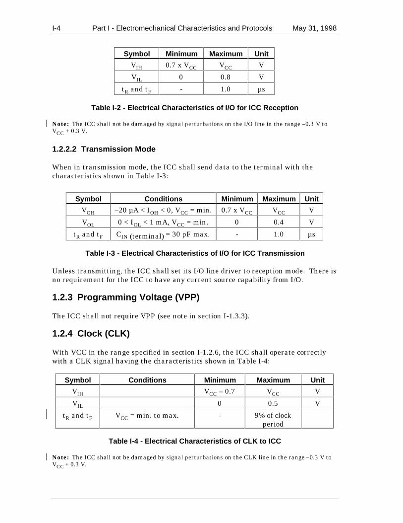
When in reception mode, and with the supply voltage (VCC) in the range specified insection I-1.2.6, the ICC shall correctly interpret signals from the terminal having thecharacteristics shown in Table I-2:
1 Defined in ISO/IEC 7816 as programming voltage (VPP).2 Electrically isolated means that the resistance measured between C6 and any other contact shall be≥10MΩ with an applied voltage of 5V DC.
I-4 Part I - Electromechanical Characteristics and Protocols May 31, 1998
Symbol Minimum Maximum Unit
VIH 0.7 x VCC VCC V
VIL 0 0.8 V
tR and tF - 1.0 µs
Table I-2 - Electrical Characteristics of I/O for ICC Reception
Note: The ICC shall not be damaged by signal perturbations on the I/O line in the range –0.3 V toVCC + 0.3 V.
1.2.2.2 Transmission Mode
When in transmission mode, the ICC shall send data to the terminal with thecharacteristics shown in Table I-3:
Symbol Conditions Minimum Maximum Unit
VOH –20 µA < IOH < 0, VCC = min. 0.7 x VCC VCC V
VOL 0 < IOL < 1 mA, VCC = min. 0 0.4 V
tR and tF CIN (terminal) = 30 pF max. - 1.0 µs
Table I-3 - Electrical Characteristics of I/O for ICC Transmission
Unless transmitting, the ICC shall set its I/O line driver to reception mode. There isno requirement for the ICC to have any current source capability from I/O.
1.2.3 Programming Voltage (VPP)
The ICC shall not require VPP (see note in section I-1.3.3).
1.2.4 Clock (CLK)
With VCC in the range specified in section I-1.2.6, the ICC shall operate correctlywith a CLK signal having the characteristics shown in Table I-4:
Symbol Conditions Minimum Maximum Unit
VIH VCC – 0.7 VCC V
VIL 0 0.5 V
tR and tF VCC = min. to max. - 9% of clockperiod
Table I-4 - Electrical Characteristics of CLK to ICC
Note: The ICC shall not be damaged by signal perturbations on the CLK line in the range –0.3 V toVCC + 0.3 V.

May 31, 1998 Part I - Electromechanical Characteristics and Protocols I-5
The ICC shall operate correctly with a CLK duty cycle of between 44% and 56% ofthe period during stable operation.
The ICC shall operate correctly with a CLK frequency in the range 1 MHz to 5 MHz.
Note: Frequency shall be maintained by the terminal to within ± 1% of that used during the answerto reset throughout the card session.
1.2.5 Reset (RST)
With VCC in the range specified in section I-1.2.6, the ICC shall correctly interpret aRST signal having the characteristics shown in Table I-5:
Symbol Conditions Minimum Maximum Unit
VIH VCC – 0.7 VCC V
VIL 0 0.6 V
tR and tF VCC = min. to max. - 1.0 µs
Table I-5 - Electrical Characteristics of RST to ICC
Note: The ICC shall not be damaged by signal perturbations on the RST line in the range –0.3 V toVCC + 0.3 V.
The ICC shall answer to reset asynchronously using active low reset.
1.2.6 Supply Voltage (VCC)
The ICC shall operate correctly with a supply voltage VCC of 5 V ± 0.5 V DC andhave a maximum current requirement of 50 mA when operating at any frequencywithin the range specified in section I-1.2.4.
Note: It is strongly recommended that the current consumption of ICCs is maintained at as low avalue as possible, since the maximum current consumption allowable for the ICC may be reduced infuture versions of this specification. Issuers of ICCs bearing multisector applications should ensurethat the IC used has a current requirement compatible with all terminals (from all sectors) in whichthe ICC might be used.
1.2.7 Contact Resistance
The contact resistance as measured across a pair of clean ICC and clean nominalIFD contacts shall be less than 500 mΩ throughout the design life of an ICC (seeISO/IEC 10373 for test method).
Note: A nominal IFD contact may be taken as a minimum of 1.25 µm of gold over 5.00 µm of nickel.

I-6 Part I - Electromechanical Characteristics and Protocols May 31, 1998
1.3 Mechanical Characteristics of the Terminal
This section describes the mechanical characteristics of the terminal interfacedevice.
1.3.1 Interface Device
The IFD into which the ICC is inserted shall be capable of accepting ICCs havingthe following characteristics:
• Physical characteristics compliant with ISO/IEC DIS 7816-1 • Contacts on the front, in the position compliant with Figure 2 of ISO/IEC DIS
7816-2 • Embossing compliant with ISO/IEC 7811-1 and 3
The IFD contacts shall be located such that if an ICC having contacts with thedimensions and locations specified in Figure I-3 is inserted into the IFD, correctconnection of all contacts shall be made.
Figure I-3 - Terminal Contact Location and Dimensions
Location guides and clamps (if used) shall cause no damage to ICCs, particularly inthe areas of the magnetic stripe, signature panel, embossing, and hologram.

May 31, 1998 Part I - Electromechanical Characteristics and Protocols I-7
Note: As a general principle, an ICC should be accessible to the cardholder at all times. Where theICC is drawn into the IFD, a mechanism should exist to return the ICC to the cardholder in the eventof a failure (for example, loss of power).
1.3.2 Contact Forces
The force exerted by any one IFD contact on the corresponding ICC contact shall bein the range 0.2 N to 0.6 N.
1.3.3 Contact Assignment
The assignment of the IFD contacts shall be as shown in Table I-6:
C1 VCC C5 GNDC2 RST C6 Not used3
C3 CLK C7 I/O
Table I-6 - IFD Contact Assignment
C4 and C8 are not used and need not be physically present. C6 shall be electricallyisolated4.
Note: If connected in existing terminals, C6 shall be maintained at a potential between GND and1.05 x VCC throughout the card session. Keeping C6 isolated in new terminals facilitates its use forother purposes if so defined in future versions of this specification.
1.4 Electrical Characteristics of the Terminal
This section describes the electrical characteristics of the signals as measured at theIFD contacts.
1.4.1 Measurement Conventions
All measurements are made at the point of contact between the ICC and the IFDcontacts and are defined with respect to GND contact over an ambient temperaturerange 0° C to 50° C.
All currents flowing out of the terminal are considered positive.
1.4.2 Input/Output (I/O)
This contact is used as an output (transmission mode) to transmit data to the ICC oras an input (reception mode) to receive data from the ICC. During operation, theterminal and the ICC shall not both be in transmit mode. In the event that this
3 Defined in ISO/IEC 7816 as programming voltage (VPP).4 Electrically isolated means that the resistance measured between C6 and any other contact shall be≥10MΩ with an applied voltage of 5V DC.

I-8 Part I - Electromechanical Characteristics and Protocols May 31, 1998
condition occurs, the state (voltage level) of the contact is indeterminate and nodamage shall occur to the terminal.
When both the terminal and the ICC are in reception mode, the contact shall be inthe high state. To achieve this, the terminal shall incorporate a pull-up resistor toVCC, or other device. The terminal shall not pull I/O high unless VCC is poweredand stable within the tolerances specified in section I-1.4.6. See the contactactivation sequence specified in section I-2.1.2.
The terminal shall limit the current flowing into or out of the I/O contact to ±15 mAat all times.
1.4.2.1 Transmission Mode
When in transmission mode, the terminal shall send data to the ICC with thecharacteristics shown in Table I-7:
Symbol Conditions Minimum Maximum Unit
VOH 0 < IOH < 20 µA, VCC =min.
0.8 x VCC VCC V
VOL - 0.5 mA < IOL < 0, VCC =min.
0 0.4 V
tR and tF CIN(ICC) = 30 pF max. - 0.8 µs
Signalperturbations
Signal low - 0.25 0.4 V
Signal high 0.8 x VCC VCC + 0.25 V
Table I-7 - Electrical Characteristics of I/O for Terminal Transmission
Unless transmitting, the terminal shall set its I/O line driver to reception mode.
1.4.2.2 Reception Mode
When in reception mode, the terminal shall correctly interpret signals from the ICChaving the characteristics shown in Table I-8:
Symbol Minimum Maximum Unit
VIH 0.6 x VCC VCC V
VIL 0 0.5 V
tR and tF - 1.2 µs
Table I-8 - Electrical Characteristics of I/O for Terminal Reception

May 31, 1998 Part I - Electromechanical Characteristics and Protocols I-9
1.4.3 Programming Voltage (VPP)
The terminal shall not generate a VPP (see section I-1.3.3).
1.4.4 Clock (CLK)
The terminal shall generate a CLK signal having the characteristics shown in TableI-9:
Symbol Conditions Minimum Maximum UnitVOH 0 < IOH < 50 µA, VCC = min. VCC – 0.5 VCC V
VOL - 50 µA < IOL < 0, VCC = min. 0 0.4 V
tR and tF CIN(ICC) = 30 pF max. - 8% of clockperiod
Signalperturbations
Signal low - 0.25 0.4 V
Signal high VCC – 0.5 VCC + 0.25 V
Table I-9 - Electrical Characteristics of CLK from Terminal
Duty cycle shall be between 45% and 55% of the period during stable operation.
Frequency shall be in the range 1 MHz to 5 MHz and shall not change by more than± 1% throughout a card session (see section I-2).
1.4.5 Reset (RST)
The terminal shall generate a RST signal having the characteristics shown in TableI-10:
Symbol Conditions Minimum Maximum Unit
VOH 0 < IOH < 50 µA, VCC = min. VCC - 0.5 VCC V
VOL - 50 µA < IOL < 0, VCC = min. 0 0.4 V
TR and tF CIN(ICC) = 30 pF max. - 0.8 µs
Signalperturbations
Signal low - 0.25 0.4 V
Signal high VCC – 0.5 VCC + 0.25 V
Table I-10 - Electrical Characteristics of RST from Terminal
I-10 Part I - Electromechanical Characteristics and Protocols May 31, 1998
1.4.6 Supply Voltage (VCC)
The terminal shall generate a VCC of 5 V ± 0.4 V DC and shall be capable ofdelivering steady state output current in the range 0 to 55 mA whilst maintainingVCC within these tolerances. The terminal shall contain protection circuitry toprevent damage occurring to it in the event of fault conditions such as a short circuitto GND or VCC. This supply shall be protected from transients and surges causedby internal operation of the terminal and from external interference introduced viapower leads, communications links, etc. VCC shall never be negative with respect toground.
During normal operation of an ICC, current pulses cause voltage transients on VCCas measured at the ICC contacts. The power supply shall be able to counteracttransients in the current consumption of the ICC up to a maximum charge of 40 nAswith no more than 400 ns duration and a maximum amplitude of 100 mA, ensuringthat VCC remains within the range specified.
Note: Terminals may be designed to be capable of delivering more than 55 mA if required, but it isrecommended that terminals limit the steady state current that can be delivered to a maximum of200 mA.
1.4.7 Contact Resistance
The contact resistance as measured across a pair of clean IFD and clean nominalICC contacts shall be less than 500 mΩ throughout the design life of a terminal (seeISO/IEC DIS 7816-1 for test method).
Note: A nominal ICC contact may be taken as 1.25 µm of gold over 5.00 µm of nickel.
1.4.8 Short Circuit Resilience
The terminal shall be capable of sustaining a short circuit of any duration betweenany or all contacts without suffering damage or malfunction, for example, if a metalplate or an ICC with a metallic surface is inserted.
1.4.9 Powering and Depowering of Terminal with ICC in Place
If the terminal is powered on or off with an ICC in place no spurious signals orpower perturbations shall appear at the interface contacts. Contact activation anddeactivation sequences and timings, as described in sections I-2.1.2 and I-2.1.5respectively shall be respected.

May 31, 1998 Part I - Electromechanical Characteristics and Protocols I-11
2. Card Session
This section describes all stages involved in a card session from insertion of the ICCinto the IFD through the execution of the transaction to the removal of the ICC fromthe IFD.
2.1 Normal Card Session
This section describes the processes involved in the execution of a normaltransaction.
2.1.1 Stages of a Card Session
A card session is comprised of the following stages:
1. Insertion of the ICC into the IFD and connection and activation of the contacts. 2. Reset of the ICC and establishment of communication between the terminal and
the ICC. 3. Execution of the transaction(s). 4. Deactivation of the contacts and removal of the ICC.
2.1.2 ICC Insertion and Contact Activation Sequence
On insertion of the ICC into the IFD, the terminal shall ensure that all signalcontacts are in state L with values of VOL as defined in section I-1.4 and that VCC is0.4 V or less before any contacts are physically made. The IFD shall be able todetect when the ICC is seated to within ±0.5 mm of the nominally correct position5
in the direction of insertion/withdrawal. When the IFD detects that the ICC isseated within this tolerance, and when all contacts have been physically made, thecontacts shall be activated as follows (see Figure I-4):
• RST shall be maintained by the terminal in state L throughout the activationsequence.
• Following establishment of the physical contacts but prior to activation of I/O or
CLK, VCC shall be powered. • Following verification by the terminal that VCC is stable and within the limits
defined in section I-1.4.6, the terminal shall set its I/O line driver to receptionmode and shall provide CLK with a suitable and stable clock as defined in sectionI-1.4.4. The I/O line driver in the terminal may be set to reception mode prior to
5 The ‘nominally correct position’ is when the centres of the IFD contacts are exactly over the centresof the ICC contacts located as specified in ISO/IEC DIS 7816-2.

I-12 Part I - Electromechanical Characteristics and Protocols May 31, 1998
application of the clock but shall be set to reception mode no later than 200 clockcycles after application of the clock.
Note: The terminal may verify the state of Vcc by measurement, by waiting sufficient time for it tostabilise according to the design of the terminal, or otherwise. The state of the I/O line after theterminal has set its I/O line driver to reception mode is dependent upon the state of the I/O linedriver in the ICC (see section I-2.1.3.1).
VCC
RST
CLK
I/O Indeterminate
200cyclesCardinsertedhere
Figure I-4 - Contact Activation Sequence
2.1.3 ICC Reset
The ICC shall answer to reset asynchronously using active low reset.
The means of transportation of the answer to reset (ATR) are described in section I-3 and its contents are described in sections I-4.2 and I-4.3.
2.1.3.1 Cold Reset
Following activation of the contacts according to section I-2.1.2, the terminal shallinitiate a cold reset and obtain an ATR from the ICC as follows (see Figure I-5):
• The terminal shall apply CLK at a notional time T0. • Within a maximum of 200 clock cycles following T0, the ICC shall set its I/O line
driver to reception mode. Since the terminal shall also have set its I/O linedriver to reception mode within this period, the I/O line is guaranteed to be instate H no later than 200 clock cycles following time T0.
• The terminal shall maintain RST in state L through time T0 and for a period of
between 40,000 and 45,000 clock cycles following time T0 to time T1, when itshall set RST to state H.
• The answer to reset on I/O from the ICC shall begin between 400 and 40,000
clock cycles after time T1 (time t1 in Figure I-5). • If the answer to reset from the ICC does not begin within this time, the terminal
shall initiate the deactivation sequence described in section I-2.1.5 (hereafterreferred to as the ‘deactivation sequence’) within 50 ms.

May 31, 1998 Part I - Electromechanical Characteristics and Protocols I-13
VCC
RST
CLK
I/O
T0 T1
t1Indeterminate Answer toReset
200cycles
Figure I-5 - Cold Reset Sequence
2.1.3.2 Warm Reset
If the ATR received following a cold reset as described in section I-2.1.3.1 does notconform to the specification in section I-4, the terminal shall initiate a warm resetand obtain an ATR from the ICC as follows (see Figure I-6):
• A warm reset shall start at a notional time T0’, at which time the terminal shallset RST to state L.
• The terminal shall maintain VCC and CLK stable and within the limits defined
in sections I-1.4.4 and I-1.4.6 throughout the warm reset sequence. • Within a maximum of 200 clock cycles following T0’, the ICC and terminal shall
set their I/O line drivers to reception mode. The I/O line therefore is guaranteedto be in state H no later than 200 clock cycles following time T0’.
• The terminal shall maintain RST in state L from time T0’ for a period of between
40,000 and 45,000 clock cycles following time T0’ to time T1’, when it shall setRST to state H.
• The answer to reset on I/O from the ICC shall begin between 400 and 40,000
clock cycles after time T1’ (time t1’ in Figure I-6). • If the answer to reset from the ICC does not begin within this time, the terminal
shall initiate the deactivation sequence within 50 ms.

I-14 Part I - Electromechanical Characteristics and Protocols May 31, 1998
VCC
RST
CLK
T0’ T1’
t1’Indeterminate Answer toReset
200cycles
I/O
Figure I-6 - Warm Reset Sequence
2.1.4 Execution of a Transaction
Selection of the application in the ICC and the subsequent exchange of informationbetween the ICC and the terminal necessary to perform a transaction are describedin Part III of this specification, and in the ICC Application Specification for PaymentSystems.
2.1.5 Contact Deactivation Sequence
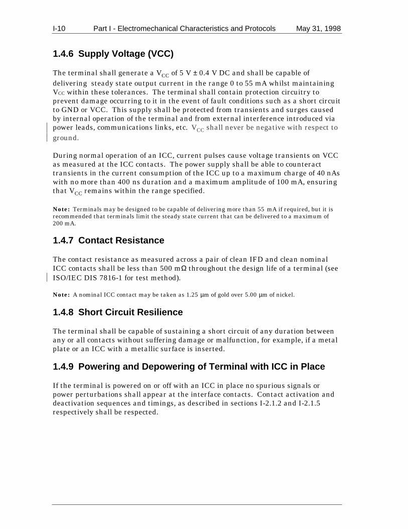
As the final step in the card session, upon normal or abnormal termination of thetransaction (including withdrawal of the ICC from the IFD during a card session),the terminal shall deactivate the IFD contacts as follows (see Figure I-7):
• The terminal shall initiate the deactivation sequence by setting RST to state L. • Following the setting of RST to state L but prior to depowering VCC, the terminal
shall set CLK and I/O to state L. • Following the setting of RST, CLK, and I/O to state L but prior to galvanic
disconnection of the IFD contacts, the terminal shall depower VCC. VCC shall be0.4 V or less prior to galvanic disconnection of the IFD contacts.
• The deactivation sequence shall be completed within 100 ms. This period is
measured from the time that RST is set to state L to the time that VCC reaches0.4 V or less.
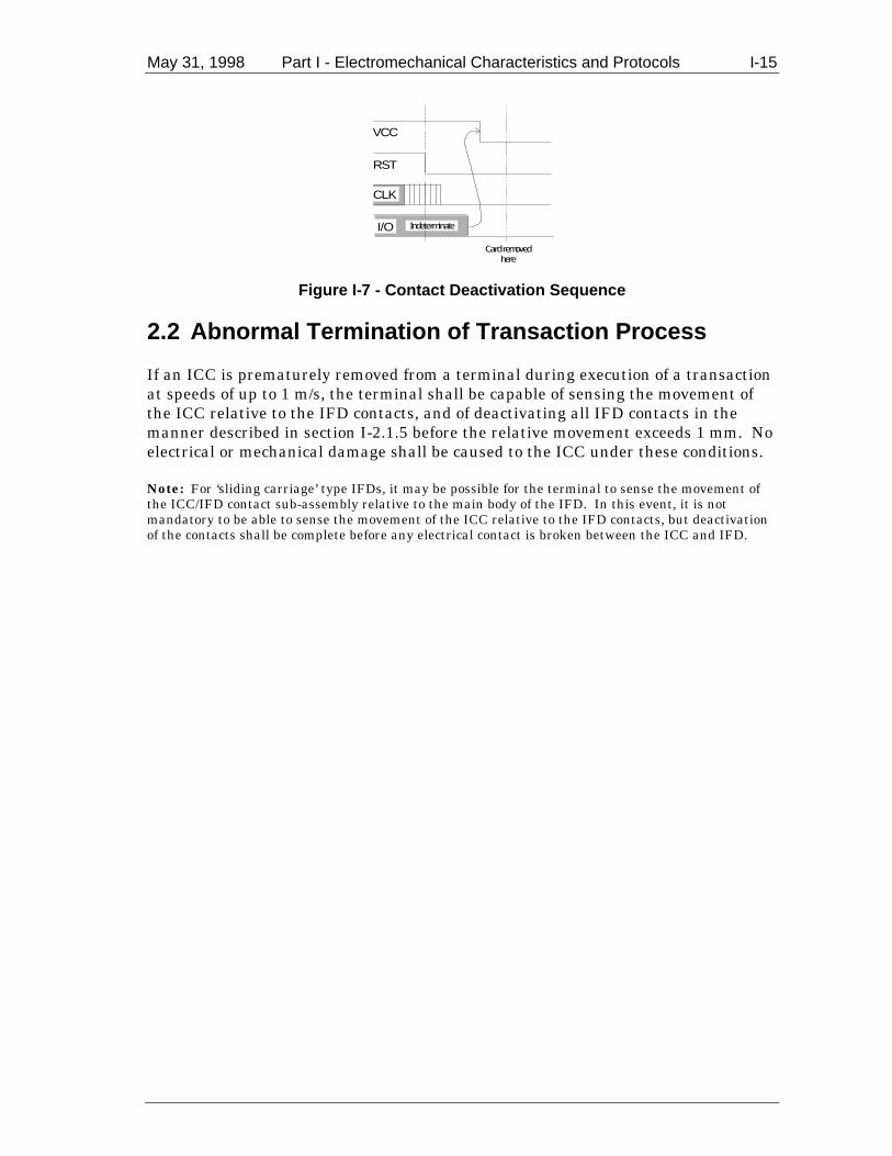
May 31, 1998 Part I - Electromechanical Characteristics and Protocols I-15
VCC
RST
CLK
Indeterminate
Cardremovedhere
I/O
Figure I-7 - Contact Deactivation Sequence
2.2 Abnormal Termination of Transaction Process
If an ICC is prematurely removed from a terminal during execution of a transactionat speeds of up to 1 m/s, the terminal shall be capable of sensing the movement ofthe ICC relative to the IFD contacts, and of deactivating all IFD contacts in themanner described in section I-2.1.5 before the relative movement exceeds 1 mm. Noelectrical or mechanical damage shall be caused to the ICC under these conditions.
Note: For ‘sliding carriage’ type IFDs, it may be possible for the terminal to sense the movement ofthe ICC/IFD contact sub-assembly relative to the main body of the IFD. In this event, it is notmandatory to be able to sense the movement of the ICC relative to the IFD contacts, but deactivationof the contacts shall be complete before any electrical contact is broken between the ICC and IFD.

I-16 Part I - Electromechanical Characteristics and Protocols May 31, 1998
3. Physical Transportation of Characters
During the transaction process, data is passed bidirectionally between the terminaland the ICC over the I/O line in an asynchronous half duplex manner. A clocksignal is provided to the ICC by the terminal, and this shall be used to control thetiming of this exchange. The mechanism of exchanging bits and characters isdescribed below. It applies during the answer to reset and is also used by bothtransmission protocols as described in section I-5.
3.1 Bit Duration
The bit duration used on the I/O line is defined as an elementary time unit (etu). Alinear relationship exists between the etu on the I/O line and CLK frequency (f).
During the answer to reset, the bit duration is known as the initial etu, and is givenby the following equation:
initial etu372
=f
seconds, where f is in Hertz
Following the answer to reset (and establishment of the global parameters F and D,see section I-4), the bit duration is known as the current etu, and is given by thefollowing equation:
current etuF
D=
f seconds, where f is in Hertz
Note: For the basic answer(s) to reset described in this specification, only values of F = 372 and
D = 1 are supported. Thus the initial and current etus are the same and are given by 372
f. In the
following sections of this specification where etu is referred to, it is current etu that is meant unlessotherwise specified.
Throughout the card session, f shall be in the range 1 MHz to 5 MHz.
3.2 Character Frame
Data is passed over the I/O line in a character frame as described below. Theconvention used is specified in the initial character (TS) transmitted by the ICC inthe ATR (see section I-4.3.1).
Prior to transmission of a character, the I/O line shall be in state H.
A character consists of 10 consecutive bits (see Figure I-8):
• 1 start bit in state L

May 31, 1998 Part I - Electromechanical Characteristics and Protocols I-17
• 8 bits, which comprise the data byte • 1 even parity checking bit
The start bit is detected by the receiving end by periodically sampling the I/O line.The sampling time shall be less than or equal to 0.2 etu.
The number of logic ones in a character shall be even. The 8 bits of data and theparity bit itself are included in this check but not the start bit.
The time origin is fixed as midway between the last observation of state H and thefirst observation of state L. The existence of a start bit shall be verified within0.7 etu. Subsequent bits shall be received at intervals of (n + 0.5 ± 0.2) etu (n beingthe rank of the bit). The start bit is bit 1.
Within a character, the time from the leading edge of the start bit to the trailingedge of the nth bit is (n ± 0.2) etu.
The interval between the leading edges of the start bits of two consecutivecharacters is comprised of the character duration (10 ± 0.2) etu, plus a guardtime.Under error free transmission, during the guardtime both the ICC and the terminalshall be in reception mode (I/O line in state H). For T=0 only, if the ICC or terminalas receiver detects a parity error in a character just received, it shall set I/O to stateL to indicate the error to the sender (see section I-5.2.3)
H
L
Start Parity Start
8 data bits
Guardtime
Character Duration10 ± 0.2 etu
I/O
Figure I-8 - Character Frame
At the terminal transport layer (TTL), data shall always be passed over the I/O linemost significant (m.s.) byte first. The order of bits within a byte (that is, whetherthe least significant (l.s.) or m.s. bit is transferred first) is specified in character TSreturned in the answer to reset (see section I-4.3).

I-18 Part I - Electromechanical Characteristics and Protocols May 31, 1998
4. Answer to Reset
After being reset by the terminal as described in section I-2.1.3, the ICC answerswith a string of bytes known as the ATR. These bytes convey information to theterminal that defines certain characteristics of the communication to be establishedbetween the ICC and the terminal. The method of transporting these bytes, andtheir meaning, is described below.
Note: In sections I-4 and I-5, the m.s. bit of a character refers to bit b8 and the l.s. bit refers to bitb1. A value in inverted commas is coded in hexadecimal notation, for example, ‘3F’.
4.1 Physical Transportation of Characters Returned atAnswer to Reset
This section describes the structure and timing of the characters returned at theanswer to reset.
The bit duration is defined in section I-3.1, and the character frame is defined insection I-3.2.
During the answer to reset, the minimum interval between the leading edges of thestart bits of two consecutive characters shall be 12 initial etus, and the maximuminterval between the leading edges of the start bits of two consecutive charactersshall be 9600 initial etus.
The ICC shall transmit all the characters to be returned during an answer to reset(warm or cold) within 19,200 initial etus6. This time is measured between theleading edge of the start bit of the first character (TS) and 12 initial etus after theleading edge of the start bit of the last character.
4.2 Characters Returned by ICC at Answer to Reset
The number and coding of the characters returned by the ICC at the answer to resetvaries depending upon the transmission protocol(s) and the values of thetransmission control parameters supported. This section describes two basicanswers to reset, one for ICCs supporting T=0 only and the other for ICCssupporting T=1 only. It defines the characters to be returned and the allowableranges of values for the transmission control parameters. ICCs returning one of thetwo answers to reset described here are assured correct operation andinteroperability in terminals conforming to this specification.
For proprietary reasons ICCs may optionally support more than one transmissionprotocol, but one of the supported protocols shall be T=0 or T=1. The first offeredprotocol shall be T=0 or T=1, and the terminal shall continue the card session using
6 The maximum time allowed for the answer to reset varies according to clock frequency, since theperiod represented by an etu is frequency dependent (see section 3.1).

May 31, 1998 Part I - Electromechanical Characteristics and Protocols I-19
the first offered protocol unless for proprietary reasons it supports a mechanism forselecting an alternative protocol offered by the ICC. Support for such a mechanismis not required by, and is beyond the scope of these specifications.
Note: This specification does not support ICCs having both T=0 and T=1 protocols present at thesame time. This can only be achieved by proprietary means beyond the scope of this specification.
Also for proprietary reasons ICCs may optionally support other values of thetransmission control parameters at the issuer’s discretion. However, such support isconsidered outside the scope of this specification and such ICCs may be rejected atterminals conforming to this specification, which need not have the correspondingadditional proprietary functionality required to support the ICC.
The characters returned by the ICC at the answer to reset for the two basic answersto reset are shown in Tables I-11 and I-12. The characters are shown in the order inwhich they are sent by the ICC, that is, TS first.
If protocol type T=0 only is supported (character-oriented asynchronoustransmission protocol), the characters returned shall be as shown in Table I-11:
Character Value RemarksTS ‘3B’ or ‘3F’ Indicates direct or inverse conventionT0 ‘6x’ TB1 and TC1 present; x indicates the number of
historical bytes presentTB1 ‘00’ VPP not requiredTC1 ‘00’ to ‘FF’ Indicates the amount of extra guardtime required.
Value ‘FF’ has a special meaning (see section I-4.3.3.3)
Table I-11 - Basic ATR for T=0 Only

I-20 Part I - Electromechanical Characteristics and Protocols May 31, 1998
If protocol type T=1 only is supported (block-oriented asynchronous transmissionprotocol), the characters returned shall be as shown in Table I-12:
Character Value RemarksTS ‘3B’ or ‘3F’ Indicates direct or inverse conventionT0 ‘Ex’ TB1 to TD1 present; x indicates the number of
historical bytes presentTB1 ‘00’ VPP not requiredTC1 ‘00’ to ‘FF’ Indicates amount of extra guardtime required.
Value ‘FF’ has special meaning - see section I-4.3.3.3
TD1 ‘81’ TA2 to TC2 absent; TD2 present; T=1 to be usedTD2 ‘31’ TA3 and TB3 present; TC3 and TD3 absent; T=1
to be usedTA3 ‘10’ to ‘FE’ Returns IFSI, which indicates initial value for
information field size for the ICC and IFSC of 16-254 bytes
TB3 m.s. nibble ‘0’ to ‘4;’l.s. nibble ‘0’ to ‘5’
BWI = 0 to 4CWI = 0 to 5
TCK See section I-4.3.4 Check character
Table I-12 - Basic ATR for T=1 Only
4.3 Character Definitions
This section provides detailed descriptions of the characters that may be returned atthe answer to reset. The presence or absence of a character, and the allowablerange of values it may take (if present) if it is to conform to one of the basic ATRs isindicated by ‘basic response’ in the description of each character. The description ofa basic response (even though indicated by ‘shall’) is not intended to preclude the useof other values of the characters, nor the omission/inclusion of a character at theissuer’s discretion. For example, the ICC may return additional characters if itsupports more than one transmission protocol (see section I-5). However, only ICCsreturning a basic ATR, or an ATR supported by the minimum required terminalfunctionality described below, are guaranteed to be supported correctly ininterchange.
Terminals conforming to this specification are only required (as a minimum) tosupport the basic ATRs described here together with any additional requirementsspecified in ‘terminal behaviour’. Terminals may thus reject an ATR not supportedby this required functionality. However, terminals may, in addition, be capable ofcorrectly interpreting an ATR that does not conform to this specification but that isreturned by an ICC for proprietary (for example, national) use. Such terminalfunctionality is not mandatory and is beyond the scope of this specification. As ageneral principle, a terminal should accept a non basic ATR if it is able to functioncorrectly with the ATR that was returned.

May 31, 1998 Part I - Electromechanical Characteristics and Protocols I-21
The maximum number of characters returned in the answer to reset (including thehistorical bytes but not including TS) shall be 32.
Terminals shall be capable of checking the parity of characters returned in theanswer to reset, but not necessarily as they are received.
In the following character descriptions, if it is indicated that a terminal shall:
• reject an ATR, it means that the terminal shall issue a warm reset if it isrejecting a cold ATR, or terminate the card session by deactivating the ICCcontacts if it rejecting a warm ATR
• reject an ICC, it means that the terminal shall terminate the card session by
deactivating the ICC contacts • accept an ATR, it means that the terminal shall accept the ATR, but only if the
requirements specified in this section for all other characters are also met.
Each character description is structured in the following way:
• title
• explanation of usage as described in ISO/IEC 7816-3
• EMV basic response. This response should always be used in a warm ATR toensure interoperability
• required terminal behaviour in the event that a terminal receives charactersoutside the range allowed by EMV
4.3.1 TS - Initial Character
TS performs two functions. It provides a known bit pattern to the terminal tofacilitate bit synchronisation, and it indicates the logic convention to be used for theinterpretation of the subsequent characters.
Using inverse logic convention, a low state L on the I/O line is equivalent to a logicone, and the m.s. bit of the data byte is the first bit sent after the start bit. Usingdirect logic convention, a high state H on the I/O line is equivalent to a logic one,and the l.s. bit of the data byte is the first bit sent after the start bit. The first fourbits LHHL are used for bit synchronisation.
Basic responses: The ICC shall return an ATR containing TS having one of twovalues:
• (H)LHHLLLLLLH - inverse convention, value ‘3F’ • (H)LHHLHHHLLH - direct convention, value ‘3B’
I-22 Part I - Electromechanical Characteristics and Protocols May 31, 1998
Terminal behaviour: The terminal shall be capable of supporting both inverse anddirect convention and shall accept an ATR containing TS having a value of either‘3B’ or ‘3F’. An ICC returning an ATR containing TS having any other value shallbe rejected.
Note: It is strongly recommended that a value of ‘3B’ is returned by the ICC since a value of ‘3F’ maynot be supported in future versions of this specification.
4.3.2 T0 - Format Character
T0 is comprised of two parts. The m.s. nibble (b5-b8) is used to indicate whether thesubsequent characters TA1 to TD1 are present. Bits b5-b8 are set to the logic onestate to indicate the presence of TA1 to TD1, respectively. The l.s. nibble (b1-b4)indicates the number of optional historical bytes present (0 to 15). (See Table I-13for the basic response coding of character T0.)
Basic responses: The ATR shall contain T0 = ‘6x’ if T=0 only is to be used, indicatingthat characters TB1 and TC1 are present. The ATR shall contain T0 = ‘Ex’ if T=1only is to be used, indicating that characters TB1 to TD1 are present. The value of‘x’ represents the number of optional historical bytes to be returned.
Terminal behaviour: The terminal shall accept an ATR containing T0 of any valueprovided that the value returned correctly indicates and is consistent with theinterface characters TA1 to TD1 and historical bytes actually returned
b8 b7 b6 b5 b4 b3 b2 b1T=0 only 0 1 1 0 x x x xT=1 only 1 1 1 0 x x x x
Table I-13 - Basic Response Coding of Character T0
4.3.3 TA1 to TC3 - Interface Characters
TA1 to TC3 convey information that shall be used during exchanges between theterminal and the ICC subsequent to the answer to reset. They indicate the values ofthe transmission control parameters F, D, I, P, and N, and the IFSC, block waitingtime integer (BWI), and character waiting time integer (CWI) applicable to T=1 asdefined in ISO/IEC 7816-3. The information contained in TA1, TB1, TC1, TA2, andTB2 shall apply to all subsequent exchanges irrespective of the protocol type to beused.
4.3.3.1 TA1
TA1 conveys the values of FI and DI where:
• FI is used to determine the value of F, the clock rate conversion factor, which maybe used to modify the frequency of the clock provided by the terminal subsequentto the answer to reset

May 31, 1998 Part I - Electromechanical Characteristics and Protocols I-23
• DI is used to determine the value of D, the bit rate adjustment factor, which may
be used to adjust the bit duration used subsequent to the answer to reset See section I-3.1 for calculation of the bit duration subsequent to the answer to reset(current etu). Default values of FI = 1 and DI = 1 indicating values of F = 372 and D = 1,respectively, shall be used during the answer to reset. Basic response: The ATR shall not contain TA1 and thus the default values ofF = 372 and D = 1 shall continue be used during all subsequent exchanges. Terminal behaviour: If TA1 is present in the ATR (indicated by b5 of T0 set to ‘1’)and TA2 is returned with b5 = ‘0’ (specific mode, parameters defined by the interfacebytes), the terminal shall: • Accept the ATR if the value of TA1 is ‘11’, and immediately implement the
values of F and D indicated.
• Reject the ATR if the value of TA1 is not ‘11’, unless it is able to support andimmediately implement the conditions indicated. Support for values of TA1other than ‘11’ is not required by this specification.
If TA1 is present in the ATR (indicated by b5 of T0 set to ‘1’) and TA2 is notreturned (negotiable mode), the terminal shall only accept the ATR if TA1 = ‘11’ andshall continue using the default values of D = 1 and F = 372 during all subsequentexchanges.
If TA1 is absent from the ATR, the default values of D = 1 and F = 372 shall be usedduring all subsequent exchanges.
Note: It is strongly recommended that new terminals shall be capable of correctly interpreting thel.s. nibble of TA1 if it is returned (that codes the bit rate adjustment factor D ), and of correctlyimplementing values of D of 1, 2, or 4. Future versions of this specification may support other valuesof D to improve data transfer rates between the TTL and ICC and a protocol type selection (PTS)mechanism for selecting the value to be used.
4.3.3.2 TB1
TB1 conveys the values of PI1 and II where:
• PI1 is specified in bits b1 to b5 and is used to determine the value of theprogramming voltage P required by the ICC. PI1 = 0 indicates that VPP is notconnected in the ICC.
• II is specified in bits b6 and b7 and is used to determine the maximum
programming current Ι required by the ICC. This parameter is not used if PI1 =0.

I-24 Part I - Electromechanical Characteristics and Protocols May 31, 1998
• Bit 8 is not used and shall be set to logic zero.
Basic response: The ATR shall contain TB1 = ‘00’, indicating that VPP is notconnected in the ICC.
Terminal behaviour: In response to a cold reset, the terminal shall accept only anATR containing TB1 = ‘00’. In response to a warm reset the terminal shall accept anATR containing TB1 of any value (provided that b6 of T0 is set to 1) or notcontaining TB1 (provided that b6 of T0 is set to 0) and shall continue the cardsession as though TB1 = ‘00’ had been returned. VPP shall never be generated.
Note: Existing terminals may maintain VPP in the idle state (see section I-1.3.3).
The basic response coding of character TB1 is shown in Table I-14:
b8 b7 b6 b5 b4 b3 b2 b10 0 0 0 0 0 0 0
Table I-14 - Basic Response Coding of Character TB1
4.3.3.3 TC1
TC1 conveys the value of N, where N is used to indicate the extra guardtime thatshall be added to the minimum duration between the leading edges of the start bitsof two consecutive characters for subsequent exchanges from the terminal to theICC. N is binary coded over bits b1-b8 of TC1, and its value represents the numberof etus to be added as extra guardtime. It may take any value between 0 and 255.N = 255 has a special meaning and indicates that the minimum delay between thestart leading edges of two consecutive characters shall be reduced to 12 etus if T=0is to be used, or 11 etus if T=1 is to be used.
Note: TC1 applies only to the timing between two consecutive characters sent from the terminal tothe ICC. It does not apply to the timing between consecutive characters sent from the ICC to theterminal, nor does it apply to the timing between two characters sent in opposite directions. Seesections I-5.2.2.1 and I-5.2.4.2.2.
If the value of TC1 is in the range ‘00’ to ‘FE’, between 0 and 254 etus of extraguardtime shall be added to the minimum character to character duration, which forsubsequent transmissions shall be between 12 and 266 etus.
If the value of TC1 = ‘FF’ the minimum character to character duration forsubsequent transmissions shall be 12 etus if T=0 is to be used, or 11 etus if T=1 is tobe used.
Basic response: The ATR shall contain TC1 having a value in the range ‘00’ to ‘FF’.

May 31, 1998 Part I - Electromechanical Characteristics and Protocols I-25
Terminal behaviour: The terminal shall accept an ATR not containing TC1(provided that b7 of T0 is set to 0), but if it accepts such an ATR it shall continue thecard session as though TC1 = ‘00’ had been returned.
The basic response coding of character TC1 is shown in Table I-15:
b8 b7 b6 b5 b4 b3 b2 b1x x x x x x x x
Table I-15 - Basic Response Coding of Character TC1
Note: It is strongly recommended that the value of TC1 be set to the minimum acceptable for theICC. Large values of TC1 lead to very slow communication between the terminal and the ICC, andthus lengthy transaction times.
4.3.3.4 TD1
TD1 indicates whether any further interface bytes are to be transmitted andinformation concerning the protocol type(s) where:
• The m.s. nibble is used to indicate whether the characters TA2 to TD2 arepresent. These bits (b5-b8) are set to the logic one state to indicate the presenceof TA2 to TD2 respectively.
• The l.s. nibble provides information concerning the protocol type(s) to be used for
subsequent exchanges.
Basic responses: The ATR shall not contain TD1 if T=0 only is to be used, andprotocol type T=0 shall be used as a default for all subsequent transmissions. TheATR shall contain TD1 = ‘81’ if T=1 only is to be used, indicating that TD2 is presentand that protocol type T=1 shall be used for all subsequent transmissions.
Terminal behaviour: The terminal shall accept an ATR containing TD1 with them.s. nibble having any value (provided that the value returned correctly indicatesand is consistent with the interface characters TA2 to TD2 actually returned), andthe l.s. nibble having a value of ‘0’ or ‘1’. The terminal shall reject an ATRcontaining other values of TD1.
The basic response coding of character TD1 is shown in Table I-16:
b8 b7 b6 b5 b4 b3 b2 b1T=1 1 0 0 0 0 0 0 1
Table I-16 - Basic Response Coding of Character TD1

I-26 Part I - Electromechanical Characteristics and Protocols May 31, 1998
4.3.3.5 TA2
The presence or absence of TA2 indicates whether the ICC is operating in specificmode or negotiable mode respectively.
Basic response: The ATR shall not contain TA2; the absence of TA2 indicates thenegotiable mode of operation.
Terminal behaviour: The terminal shall accept an ATR containing TA2 providedthat b5 = 0, and that it is able to support the exact conditions indicated by theinterface parameters returned by the ICC in the answer to reset and immediatelyuses those conditions. Otherwise, the terminal shall reject an ATR containing TA2.
4.3.3.6 TB2
TB2 conveys PI2 that is used to determine the value of programming voltage Prequired by the ICC. When present it overrides the value indicated by PI1 returnedin TB1.
Basic response: The ATR shall not contain TB2.
Terminal behaviour: The terminal shall reject an ATR containing TB2.
Note: Existing terminals may maintain VPP in the idle state (see section I -1.3.3).
4.3.3.7 TC2
TC2 is specific to protocol type T=0 and conveys the work waiting time integer (WI)that is used to determine the maximum interval between the start leading edge ofany character sent by the ICC and the start leading edge of the previous charactersent either by the ICC or the terminal (the work waiting time). The work waitingtime is given by 960 x D x WI.
Basic response: The ATR shall not contain TC2 and a default value of WI = 10 shallbe used during subsequent communication.
Terminal behaviour: The terminal shall accept an ATR containing TC2 = ‘0A’. Itshall reject an ATR containing TC2 = ‘00’, or TC2 > ‘0A’. It shall reject an ATRcontaining TC2 having a value in the range ‘01’ to ‘09’ unless it is able to support it.
4.3.3.8 TD2
TD2 indicates whether any further interface bytes are to be transmitted and theprotocol type to be used for subsequent transmissions, where:
• The m.s. nibble is used to indicate whether the characters TA3 to TD3 arepresent. These bits (b5-b8) are set to the logic one state to indicate the presenceof TA3 to TD3, respectively.
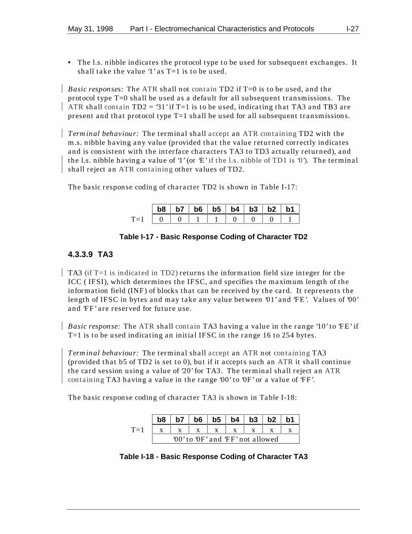
May 31, 1998 Part I - Electromechanical Characteristics and Protocols I-27
• The l.s. nibble indicates the protocol type to be used for subsequent exchanges. It
shall take the value ‘1’ as T=1 is to be used.
Basic responses: The ATR shall not contain TD2 if T=0 is to be used, and theprotocol type T=0 shall be used as a default for all subsequent transmissions. TheATR shall contain TD2 = ‘31’ if T=1 is to be used, indicating that TA3 and TB3 arepresent and that protocol type T=1 shall be used for all subsequent transmissions.
Terminal behaviour: The terminal shall accept an ATR containing TD2 with them.s. nibble having any value (provided that the value returned correctly indicatesand is consistent with the interface characters TA3 to TD3 actually returned), andthe l.s. nibble having a value of ‘1’ (or ‘E’ if the l.s. nibble of TD1 is ‘0’). The terminalshall reject an ATR containing other values of TD2.
The basic response coding of character TD2 is shown in Table I-17:
b8 b7 b6 b5 b4 b3 b2 b1T=1 0 0 1 1 0 0 0 1
Table I-17 - Basic Response Coding of Character TD2
4.3.3.9 TA3
TA3 (if T=1 is indicated in TD2) returns the information field size integer for theICC ( IFSI), which determines the IFSC, and specifies the maximum length of theinformation field (INF) of blocks that can be received by the card. It represents thelength of IFSC in bytes and may take any value between ‘01’ and ‘FE’. Values of ‘00’and ‘FF’ are reserved for future use.
Basic response: The ATR shall contain TA3 having a value in the range ‘10’ to ‘FE’ ifT=1 is to be used indicating an initial IFSC in the range 16 to 254 bytes.
Terminal behaviour: The terminal shall accept an ATR not containing TA3(provided that b5 of TD2 is set to 0), but if it accepts such an ATR it shall continuethe card session using a value of ‘20’ for TA3. The terminal shall reject an ATRcontaining TA3 having a value in the range ‘00’ to ‘0F’ or a value of ‘FF’.
The basic response coding of character TA3 is shown in Table I-18:
b8 b7 b6 b5 b4 b3 b2 b1T=1 x x x x x x x x
‘00’ to ‘0F’ and ‘FF’ not allowed
Table I-18 - Basic Response Coding of Character TA3

I-28 Part I - Electromechanical Characteristics and Protocols May 31, 1998
4.3.3.10 TB3
TB3 (if T=1 is indicated in TD2) indicates the values of the CWI and the BWI usedto compute the CWT and BWT respectively. TB3 is comprised of two parts. The l.s.nibble (b1-b4) is used to indicate the value of CWI, whilst the m.s. nibble (b5-b8) isused to indicate the value of BWI.
Basic response: The ATR shall contain TB3 having the l.s. nibble in the range ‘0’ to‘5’, and the m.s. nibble in the range ‘0’ to ‘4’ if T=1 is to be used, indicating values of0 to 5 for CWI and 0 to 4 for BWI.
The basic response coding of character TB3 is shown in Table I-19:
b8 b7 b6 b5 b4 b3 b2 b1T=1 0 x x x 0 y y y
xxx is in the range 000 to 100yyy is in the range 000 to 101
Table I-19 - Basic Response Coding of Character TB3
Terminal behaviour: The terminal shall reject an ATR not containing TB3, orcontaining a TB3 indicating BWI greater than 4 and/or CWI greater than 5, orhaving a value such that 2CWI < (N + 1). It shall accept an ATR containing a TB3having any other value.
Note: N is the extra guardtime indicated in TC1. If TC1=255, the value of N shall be taken as -1.
4.3.3.11 TC3
TC3 (if T=1 is indicated in TD2) indicates the type of block error detection code to beused. The type of code to be used is indicated in b1, and b2 to b8 are not used.
Basic response: The ATR shall not contain TC3, thus indicating longitudinalredundancy check (LRC) as the error code to be used.
Terminal behaviour: The terminal shall accept an ATR containing TC3 = ‘00’. Itshall reject an ATR containing TC3 having any other value.
4.3.4 TCK - Check Character
TCK has a value that allows the integrity of the data sent in the ATR to be checked.The value of TCK is such that the exclusive-OR’ing of all bytes from T0 to TCKinclusive is null.
Basic responses: The ATR shall not contain TCK if T=0 only is to be used. In allother cases TCK shall be returned in the ATR.

May 31, 1998 Part I - Electromechanical Characteristics and Protocols I-29
Terminal behaviour: The terminal shall accept an ICC returning an ATR notcontaining TCK if T=0 only is indicated. In all other cases, the terminal shall rejectan ICC returning an ATR not containing TCK or containing an incorrect TCK, andshall be able to evaluate TCK when appropriately returned. If TCK is incorrect, theterminal shall initiate the deactivation sequence within 4,800 initial etus followingthe leading edge of the start bit of TCK. For either protocol, the terminal maycontinue the card session as soon as the last character indicated by the bit mapcharacters T0 and/or TDi has been received. The terminal shall wait at least theguardtime applicable to the protocol to be used (16 etus for T=0, BGT for T=1) beforetransmitting.
Note: If TCK is not returned, bullet 3 of section I-4.4 applies.
4.4 Terminal Behaviour during Answer to Reset
Following activation of the ICC contacts as described in section I-2.1.2 the terminalshall initiate a cold reset as described in section I-2.1.3.1. Subsequently thefollowing shall apply:
• If the terminal rejects a cold ATR as described in section I-4.3, it shall notimmediately abort the card session but shall initiate a warm reset within 4,800initial etus (reaction time) measured from the leading edge of the start bit of thelast received character of the cold ATR to the time that RST is set low.
• If the terminal rejects a warm ATR as described in section I-4.3, it shall initiate
the deactivation sequence within 4,800 initial etus measured from the leadingedge of the start bit of the last received character of the warm ATR.
• If during the answer to either a cold reset or warm reset the time between two
consecutive characters exceeds 9,600 initial etus as defined in section I-4.1, theterminal shall abort the card session by initiating the deactivation sequencewithin 14,400 initial etus (4,800 + 9,600 initial etus) following the leading edgeof the start bit of the last received character.
• If the answer to a cold or warm reset is not complete within 19,200 initial etus as
defined in section I-4.1, the terminal shall abort the card session by initiating thedeactivation sequence within 24,000 initial etus (4,800 + 19,200 initial etus)following the leading edge of the start bit of the TS character.
• If the terminal detects a parity error in a character returned during ATR, it shall
abort the card session by initiating the deactivation sequence within 4,800 initialetus measured from the leading edge of the start bit of the last receivedcharacter of the ATR.
• Upon receipt of a valid cold or warm reset complying with the timings described
above, the terminal shall proceed with the card session using the returnedparameters.

I-30 Part I - Electromechanical Characteristics and Protocols May 31, 1998
4.5 Answer to Reset - Flow at the Terminal
Figure I-9 illustrates an example of the process of an ICC returning an ATR to theterminal and the checks performed by the terminal to ensure conformance to sectionI-4.
Note 1: ’Case’ is a process variable used to indicate whether a cold orwarm reset is operative. Case = 1 for a cold reset, and Case = 2 for awarm reset.
Note 2: If the process aborts at this point, the ICC may be acceptable inthis terminal by business agreement. The terminal should be primed toaccept the ICC prior to insertion. Any subsequent processing isproprietary and beyond the scope of this specification.
Note 3: If the process aborts at this point, reset may be retried afterremoving the ICC from the terminal and taking corrective action asrequired. An appropriate message should be displayed on the terminal.
Note 4: A proprietary card session beyond the scope of thisspecification may be started at this point.
START
Is ATRcheck 1 OK?
Warm Reset Set Case = 2
Is ATRcheck 2 OK?
Is Case = 1?
Continue usingparameters
determined above
OR
(See Note 4)
Cold Reset
Set Case = 1(See Note 1)
No
No
No
Yes
Yes
Yes
ABORT(See Note 3)
ABORT(See Note 2)
ATR check 2 is OK ifthe parameters andstructure of the ATRconform to therequirements ofsection 4
OR
a proprietary ATR isrecognised
ATR check 1 isOK if parity andTCK (if returned)are correct, andthe timingsspecified insection 4.4 arerespected
Figure I-9 - ATR - Example Flow at the Terminal

May 31, 1998 Part I - Electromechanical Characteristics and Protocols I-31
5. Transmission Protocols
This section defines the structure and processing of commands initiated by theterminal for transmission control and for specific control in asynchronous halfduplex transmission protocols.
Two types of protocol are defined, character protocol (T=0) and block protocol (T=1).ICCs shall support either protocol T=0 or protocol T=1. Terminals shall supportboth protocol T=0 and T=1. The protocol to be used for subsequent communicationbetween the ICC and terminal is indicated in TD1, and shall be T=0 or T=1. If TD1is absent in the ATR, T=0 is assumed. The protocol indicated by the ICC appliesimmediately after the answer to reset, as there is no PTS procedure. Otherparameters provided in the ATR and relevant to a specific protocol are defined in therespective parts of this section.
The protocols are defined according to the following layering model:
• Physical layer, which describes the exchanges of bits and is common to bothprotocols.
• Data link layer, which includes the following sub-definitions:
− Character frame, defining the exchanges of characters common to bothprotocols.
− Character protocol T=0, defining the exchange of characters specific to
T=0. − Error detection and correction specific to T=0. − Block protocol T=1, defining the exchanges of blocks specific to T=1. − Error detection and correction specific to T=1.
• Transport layer, which defines the transmission of application-oriented messages
specific to each protocol. • Application layer, which defines the exchange of messages according to an
application protocol that is common to both transmission protocols.
5.1 Physical Layer
Both protocols T=0 and T=1 use the physical layer and character frame as defined insection I-3.

I-32 Part I - Electromechanical Characteristics and Protocols May 31, 1998
5.2 Data Link Layer
This section describes the timing, specific options, and error handling for protocolsT=0 and T=1.
5.2.1 Character Frame
The character frame as defined in section I-3.2 applies to all messages exchangedbetween the ICC and the terminal.
5.2.2 Character Protocol T=0
5.2.2.1 Specific Options - Character Timing for T=0
The minimum interval between the leading edges of the start bits of two consecutivecharacters sent by the terminal to the ICC shall be between 12 and 266 etus asindicated by the value of TC1 returned at the answer to reset (see sections I-4.2 andI-4.3).
The minimum interval between the leading edges of the start bits of two consecutivecharacters sent by the ICC to the terminal shall be 12 etus
The maximum interval between the start leading edge of any character sent by theICC and the start leading edge of the previous character sent either by the ICC orthe terminal (the Work Waiting Time) shall not exceed 960 x D x WI etus. (D andWI are returned in TA1 and TC2 ,respectively.) If the Work Waiting Time isexceeded, the terminal shall initiate the deactivation sequence within 960 etus.
The minimum interval between the leading edges of the start bits of two consecutivecharacters sent in opposite directions shall be 16 etus.
Note: The minimum interval between the leading edges of the start bits of two consecutivecharacters sent by the terminal to the ICC is always governed by the value of TC1, and may be lessthan the minimum interval of 16 etus allowed between two characters sent in opposite directions.
5.2.2.2 Command Header
A command is always initiated by the terminal application layer (TAL) which sendsan instruction via the TTL to the ICC in the form of a five byte header called thecommand header. The command header is comprised of five consecutive bytes, CLA,INS, P1, P2, and P3, where:
• CLA is the command class. • INS is the instruction code. • P1 and P2 contain additional instruction specific parameters.

May 31, 1998 Part I - Electromechanical Characteristics and Protocols I-33
• P3 indicates either the length of data to be sent with the command to the ICC, orthe maximum length of data expected in the response from the ICC, depending onthe coding of INS.
These bytes together with any data to be sent with the command constitute thecommand transport protocol data unit (C-TPDU) for T=0. The mapping of thecommand application protocol data unit (C-APDU) onto the C-TPDU is described insection I-5.3.
The TTL transmits the five-byte header to the ICC and waits for a procedure byte.
5.2.2.3 Command Processing
Following reception of a command header by the ICC, the ICC shall return aprocedure byte or status bytes SW1 SW2 (hereafter referred to as ‘status’) to theTTL. Both the TTL and ICC shall know implicitly at any point during exchange ofcommands and data between the TTL and the ICC what the direction of data flow isand whether it is the TTL or the ICC that is driving the I/O line.
5.2.2.3.1 Procedure Byte
The procedure byte indicates to the TTL what action it shall take next. The codingof the byte and the action that shall be taken by the TTL is shown in Table I-20.
Procedure Byte Value ActionEqual to INS byte All remaining data bytes shall be transferred by
the TTL, or the TTL shall be ready to receive allremaining data bytes from the ICC
Equal to complement ofINS byte ( INS )
The next data byte shall be transferred by theTTL, or the TTL shall be ready to receive thenext data byte from the ICC
‘60’ The TTL shall provide additional work waitingtime as defined in this section
‘61’ The TTL shall wait for a second procedure bytethen send a GET RESPONSE command headerto the ICC with a maximum length of ‘xx’, where‘xx’ is the value of the second procedure byte
‘6C’ The TTL shall wait for a second procedure bytethen immediately resend the previous commandheader to the ICC using a length of ‘xx’, where‘xx’ is the value of the second procedure byte
Table I-20 - Terminal Response to Procedure Byte
In all cases, after the action has taken place the TTL shall wait for a furtherprocedure byte or status.

I-34 Part I - Electromechanical Characteristics and Protocols May 31, 1998
5.2.2.3.2 Status Bytes
The status bytes indicate to the TTL that command processing by the ICC iscomplete. The meaning of the status bytes is related to the command beingprocessed and is defined in Part II of these specifications.
First Status Byte Value Action‘6x’ or ‘9x’ (except ‘60’, ‘61’and ‘6C’) - status byte SW1
TTL shall wait for a further status byte (statusbyte SW2)
Table I-21 - Status Byte Coding
Following receipt of the second status byte, the TTL shall return the status bytes(together with any appropriate data - see section I-5.3.1) to the TAL in the responseAPDU (R-APDU) and await a further C-APDU.
5.2.2.3.3 Error Handling
When awaiting a procedure byte or status byte, if the byte returned by the ICC hasa value other than specified in sections I-5.2.2.3.1 and I-5.2.2.3.2, the terminal shallinitiate the deactivation sequence within 9,600 etus following the leading edge of thestart bit of the (invalid) byte received.
5.2.2.4 Transportation of C-APDUs
A C-APDU containing only command data to be sent to the ICC, or only expectingdata in response from the ICC (cases 2 and 3 in section I-5.4), is mapped withoutchange onto a T=0 C-TPDU. A C-APDU that contains and expects no data, or aC-APDU that requires data transmission to and from the ICC (cases 1 and 4 insection I-5.4) is translated according to the rules defined in section I-5.3 fortransportation by a C-TPDU for T=0.
5.2.3 Error Detection and Correction for T=0
This procedure is mandatory for T=0 but does not apply during the answer to reset.
If a character is not received correctly or is received correctly but with incorrectparity, the receiver shall indicate an error by setting the I/O line to state L at time(10.5 ± 0.2) etus following the leading edge of the start bit of the character for aminimum of 1 etu and a maximum of 2 etus.
The transmitter shall test the I/O line (11 ± 0.2) etus after the leading edge of thestart bit of a character was sent, and assumes that the character was correctlyreceived if the I/O line is in state H.
If the transmitter detects an error, it shall repeat the disputed character after adelay of at least 2 etus following detection of the error. The transmitter shall repeatthe same disputed character a maximum of three more times.

May 31, 1998 Part I - Electromechanical Characteristics and Protocols I-35
If the last repetition is unsuccessful, the terminal shall initiate the deactivationsequence within 960 etus following reception of the leading edge of the start bit ofthe invalid character (if it is the receiver), or within 960 etus following detection ofthe signaling of the parity error by the ICC (if it is the transmitter).
5.2.4 Block Protocol T=1
The protocol consists of blocks transmitted between the TAL and the ICC to conveycommand and R-APDUs and transmission control information (for example,acknowledgment).
The data link layer block frame structure, specific options of the protocol, andprotocol operations (including error handling) are defined below.
5.2.4.1 Block Frame Structure
The character frame as defined in section I-3.2 applies.
The block is structured as follows (see Table I-22):
• Mandatory prologue field • Optional information field • Mandatory epilogue field
Prologue Field Information Field Epilogue FieldNode
Address(NAD)
ProtocolControl Byte
(PCB)
Length(LEN)
APDU or ControlInformation (INF)
ErrorDetection
Code (EDC)1 byte 1 byte 1 byte 0-254 bytes 1 byte
Table I-22 - Structure of a Block
5.2.4.1.1 Prologue Field
The prologue field consists of three mandatory bytes:
• Node address to identify source and intended destination of the block and toprovide VPP state control
• Protocol control byte to control data transmission • Length of the optional information field

I-36 Part I - Electromechanical Characteristics and Protocols May 31, 1998
5.2.4.1.1.1 Node Address
Bits b1-b3 of NAD indicate the source node address (SAD) of the block, whilst bitsb5 -b7 indicate the intended destination node address (DAD) of the block. Bitsb4 and b87 are unused and shall be set to 0.
These specifications do not support node addressing. All blocks transmitted byeither the terminal or ICC in support of EMV defined applications shall have theNAD byte set to ‘00’.
If during the card session the terminal or ICC receives a block with a NAD ≠ ‘00’, itmay treat the block as invalid. In this event, it shall apply the error detection andcorrection techniques described in section I-5.2.5.
Note: Support for node addressing is not required by this specification and interoperability can onlybe guaranteed if the requirements of this section are met. However, terminals and ICCs may forproprietary reasons support node addressing. An ICC that optionally supports node addressingshould work correctly with terminals/applications compliant with these specifications. A terminalthat optionally supports node addressing must set NAD = ‘00’ when working with ICCs/applicationscompliant with these specifications.
5.2.4.1.1.2 Protocol Control Byte
The PCB codes the type of block. There are three types of blocks defined as follows:
• Information block (I-block) used to convey APDUs. • Receive-ready block (R-block) used to convey acknowledgments (ACK or NAK). • Supervisory block (S-block) used to exchange control information.
The coding of the PCB depends on its type and is defined in Tables I-23 to I-25.
b8 0b7 Sequence numberb6 Chaining (more data)
b5-b1 Reserved for future use (RFU)
Table I-23 - Coding of the PCB of an I-block
7 Defined in ISO/IEC 7816 as VPP control. A value of 0 indicates that VPP shall be maintained in theidle state.

May 31, 1998 Part I - Electromechanical Characteristics and Protocols I-37
b8 1b7 0b6 0b5 Sequence number
b4-b1 0 = Error free1 = EDC and/or parity error2 = Other error(s)Other values RFU
Table I-24 - Coding of the PCB of an R-block
b8 1b7 1b6 0 = Request
1 = Responseb5-b1 0 = Resynchronisation request
1 = Information field size request2 = Abort request3 = Extension of BWT request4 = VPP error8
Other values RFU
Table I-25 - Coding of the PCB of a S-block
5.2.4.1.1.3 Length
The LEN codes the length of the INF part of the block; it may range from 0 to 254depending on the type of block.
Note: This specification does not support I -blocks with LEN = 0.
5.2.4.1.2 Information Field
The INF is conditional. When present in an I-block, it conveys application data.When present in a S-block, it conveys control information. An R-block shall notcontain an INF.
5.2.4.1.3 Epilogue Field
The Epilogue Field contains the EDC of the transmitted block. A block is invalidwhen a parity error and/or an EDC error occurs. This specification only supports theLRC as EDC. The LRC is one byte in length and is calculated as the exclusive-OR ofall the bytes starting with the NAD and including the last byte of INF, if present.
Note: TCi (i > 2), which indicates the type of error detection code to be used, is not returned by theICC in the ATR. The normal default of the LRC is thus used for the EDC.
8 Not used by ICCs and terminals conforming to this specification.

I-38 Part I - Electromechanical Characteristics and Protocols May 31, 1998
5.2.4.1.4 Block Numbering
I-blocks are numbered using a modulo-2 number coded on one bit. The numberingsystem is maintained independently at the ICC and the terminal as senders. Thevalue of the number starts with zero for the first I-block sent after the answer toreset by a sender and is incremented by one after sending each I-block. The numberis reset to zero by the sender after resynchronisation.
R-blocks are numbered using a modulo-2 number coded on one bit. A R-block maybe used to acknowledge a chained I-block or to request retransmission of an invalidblock, and always carries the sequence number of the next I-block its sender expectsto receive.
A S-block carries no number.
5.2.4.2 Specific Options
This section defines the information field sizes and timings to be used with protocoltype T=1.
5.2.4.2.1 Information Field Sizes
The IFSC is the maximum length of the information field of blocks that can bereceived by the ICC, and is defined as follows. At the answer to reset the IFSI isreturned by the ICC in TA3 indicating the size of the IFSC that can beaccommodated by the ICC. IFSI may take values in the range ‘10’ to ‘FE’ that codevalues for IFSC in the range 16 to 254 bytes. The maximum block size that can bereceived by the ICC is therefore (IFSC + 3 + 1) bytes including the prologue andepilogue fields. The size established during the answer to reset shall be usedthroughout the rest of the card session or until a new value is negotiated by the ICCby sending a S(IFS request) block to the terminal.
The information field size for the terminal (IFSD) is the maximum length of theinformation field of blocks that can be received by the terminal. The initial sizeimmediately following the answer to reset shall be 254 bytes, and this size shall beused throughout the rest of the card session. The first block sent by the terminalfollowing the answer to reset shall be an S(IFS request) with IFSD = 254.
5.2.4.2.2 Timing for T=1
The minimum interval between the leading edges of the start bits of two consecutivecharacters sent by the terminal to the ICC shall be between 11 and 266 etus asindicated by the value of TC1 returned at the answer to reset (see sections I-4.2 andI-4.3).
The minimum interval between the leading edges of the start bits of two consecutivecharacters sent by the ICC to the terminal shall be 11 etus
May 31, 1998 Part I - Electromechanical Characteristics and Protocols I-39
The maximum interval between the leading edges of the start bits of twoconsecutive characters in the same block (the CWT shall not exceed (2CWI + 11) etus.The CWI shall have a value of 0 to 5 as described in section I-4.3.3.6, and thus CWTlies in the range 12 to 43 etus.
The maximum interval between the leading edge of the start bit of the lastcharacter that gave the right to send to the ICC and the leading edge of the start bitof the first character sent by the ICC (the BWT) shall not exceed(2BWI x 960) + 11 etus. The BWI shall have a value in the range 0 to 4 as describedin section I-4.3.3.6, and thus BWT lies in the range 971 to 15,371 etus.
The minimum interval between the leading edges of the start bits of two consecutivecharacters sent in opposite directions (the block guard time, BGT) shall be 22 etus.
Note: In general, for values of FI and DI other than 1, BWT is calculated using the formula:
BWTD
FetuBWI= × ×
+
2 960
37211
5.2.4.3 Error Free Operation
The protocol rules for error free operation are as follows:
• The first block transmitted after the answer to reset shall be sent by theterminal to the ICC and shall be a S-block.
• If the terminal wishes to change the size of the IFSD it shall send a S(IFS
request) block to the ICC. The PCB of the S(IFS request) block shall have thevalue ‘C1’ indicating a request to change the IFSD. The INF field shall contain abyte the value of which indicates the size in bytes of the requested new IFSD.The ICC shall return a S(IFS response) block to the terminal acknowledging thechange to the size of the IFSD. The PCB of the S(IFS response) block sent inresponse shall have the value ‘E1’, and the INF field shall have the same valueas the INF field of the block requesting the change.
Note: Terminals complying with this specification shall set IFSD to 254 in the first block sentfollowing the answer to reset, and should not send any further S(IFS request) blocks during thecard session.
• If the ICC wishes to change the size of the IFSC from the initial value indicated
at the answer to reset, it shall send a S(IFS request) block to the terminal. ThePCB of the S(IFS request) block shall have the value ‘C1’ indicating a request tochange the IFSC. The INF field shall contain a byte the value of which indicatesthe size in bytes of the requested new IFSC. This byte shall have a value in therange ‘10’ to ‘FE’. The terminal shall return a S(IFS response) block to the ICCacknowledging the change to the size of the IFSC. The PCB of the S(IFSresponse block sent in response shall have the value ‘E1’, and the INF field shallhave the same value as the INF field of the block requesting the change.

I-40 Part I - Electromechanical Characteristics and Protocols May 31, 1998
• The SAD and DAD in the first block transmitted by the terminal shall be set tozero indicating that node addressing is not to be used.
Note: If for proprietary reasons the terminal supports node addressing, the SAD and DAD inthe first block transmitted by the terminal should be set to the values to be used throughout therest of the card session.
• During the card session, only blocks as defined in this section shall be
exchanged. The half duplex block protocol consists of transmitting blocksalternately by the terminal and the ICC. When the sender has transmitted acomplete block, the sender switches to the receiving state.
• When the receiver has received the number of characters in accordance with the
value of LEN and the EDC, the receiver gains the right to send. • The ICC shall acknowledge an I-block transmitted by the terminal. The
acknowledgment is indicated in the sequence number of the I-block, or theR-block if chaining is in use (except the last block of the chain), that the ICCreturns to the terminal.
• An I-block is considered by the sender to be acknowledged when the sequence
number of the I-block received in response differs from the sequence number ofthe previously received I-block. If no I-block was previously received, thesequence number of the I-block sent in response shall be 0.
• During chaining, an I-block is considered by the sender to be acknowledged when
the sequence number of the R-block sent in response differs from the sequencenumber of the I-block being acknowledged and it has bits b4-b1 set to ‘0’(indicating an error free block).
• If the ICC requires more than the BWT to process the previously received
I-block, it sends a waiting time extension request S(WTX request) block, wherethe INF contains the one-byte binary integer multiplier of the BWT valuerequested. The terminal shall acknowledge by sending a waiting time extensionresponse S(WTX response) block with the same value in the INF. The timeallocated (which is the time requested in the S(WTX request) block, and whichreplaces BWT for this instance only) starts at the leading edge of the lastcharacter of the S(WTX response) block. After the ICC responds, BWT is againused as the time allowed for the ICC to process the I-block.
• S-blocks are only used in pairs. A S(request) block is always followed by a
S(response) block.
When synchronisation as outlined above is lost, the procedure described in section I-5.2.5 shall apply.
May 31, 1998 Part I - Electromechanical Characteristics and Protocols I-41
5.2.4.4 Chaining
When the sender has to transmit data of length greater than IFSC or IFSD bytes, itshall divide it into several consecutive I-blocks. The transmission of these multipleI-blocks is achieved using the chaining function described below.
The chaining of I-blocks is controlled by b6 of the PCB. The coding of b6 is asfollows:
• b6 = 0 Last block of the chain • b6 = 1 Subsequent block follows
Any I-block with b6 = 1 shall be acknowledged by an R-block according to section I-5.2.4.1.
The last block of a chain sent by the terminal shall be acknowledged by either anI-block if correctly received, or an R-block if incorrectly received. The last block of achain sent by the ICC shall be acknowledged by an R-block if incorrectly received; ifcorrectly received, the terminal will only transmit further I-blocks if anothercommand is to be processed.
5.2.4.4.1 Rules for Chaining
The TTL shall support chaining for both transmitted and received blocks. The ICCmay optionally chain blocks sent to the terminal. Chaining is only possible in onedirection at a time. The following rules for chaining apply:
• When the terminal is the receiver, the terminal shall accept a sequence ofchained I-blocks sent from the ICC of length ≤ IFSD bytes per block.
• When the ICC is the receiver, the ICC shall accept a sequence of chained I-blocks
sent from the terminal all having length LEN = IFSC except the last block,whose length may be in the range 1 to IFSC bytes inclusive.
• When the ICC is the receiver, the ICC shall reject an I-block sent by the terminal
of length > IFSC using an R-block with bits b4-b1 of the PCB having a value of‘2’ (see Table I-24).
• If the ICC as sender chains blocks sent to the terminal it shall send I-blocks of
length ≤IFSD bytes per block • When the terminal is the sender, all I-blocks of a chain sent to the ICC shall
have LEN = IFSC bytes except the last, which shall have a length in the range 1to IFSC bytes inclusive.

I-42 Part I - Electromechanical Characteristics and Protocols May 31, 1998
5.2.4.4.2 Construction of Chained Blocks
C-APDUs are transported from the TTL to the ICC in the INF field of I-blocks (seesection I-5.3.2). If a C-APDU is too large to fit in one block, it is chained overseveral as illustrated in the following example.
Block(1) CLA INS P1 P2 Lc Data Data
Block(2) Data Data Data
Block(n) Data Data Le
The data and status returned by the ICC may optionally be chained over severalI-blocks as follows.
Block(1) Data Data Data
Block(2) Data Data Data
Block(n) Data Data SW1 SW2
Note: The above examples are for a case 4 command and show only the INF fields of the chainedblocks. Each block also has a prologue and epilogue field. All chained blocks shall contain an INFfield having a length in the range 1 to IFSD bytes if the ICC is the sender, or IFSC bytes duringchaining and 1 to IFSC bytes in the last block of the chain if the terminal is the sender.
5.2.5 Error Detection and Correction for T=1
The following errors shall be detected by the TTL:
• Transmission error including parity error, EDC error, and BWT time-out.
Note: If a parity error is detected, character repetition shall not be implemented when usingT=1.
• Loss of synchronisation (under run or overrun of the number of characters). • Protocol error (infringement of the rules of the protocol). • Abort request for a chain of blocks.
Error recovery is attempted in the following manner.
The TTL shall attempt error recovery by trying the following techniques in the ordershown.
1. Retransmission of blocks 2. Deactivation of the ICC contacts

May 31, 1998 Part I - Electromechanical Characteristics and Protocols I-43
The ICC shall attempt error recovery by trying retransmission of blocks.
If a block is retransmitted, the retransmitted block shall be identical to theoriginally transmitted block.
Note: In some terminals the TTL may not be solely responsible for error handling. Where ‘TTL’ isused it includes any functionality present in the terminal as applicable.
5.2.5.1 Protocol Rules for Error Handling
The following rules apply for error handling and correction. In each case where aR-block is sent, the l.s. nibble shall be set to ‘1’ for EDC/parity errors or ‘2’ for othererrors (including protocol errors) as defined in Table I-24.
• If the first block received by the ICC after the answer to reset is invalid, it shallreturn an R-block to the TTL with b5 = 0 and NAD = 0.
• If there is no response from the ICC to any block sent by the TTL within time
BWT (or WTX if waiting time extension has been negotiated), or the timebetween the start bits of the leading edges of two consecutive characters sent bythe ICC exceeds CWT, the terminal shall terminate the card session by initiatingthe deactivation sequence within 4,800 etus.
• If an invalid block is received in response to an I-block, the sender shall transmit
a R-block with b5 set to the number of the next I-block it had expected to receive. • If an invalid block is received in response to a R-block, the sender shall
retransmit the R-block. • If a S(... response) block is not received in response to a S(... request) block, the
sender shall retransmit the S(... request) block. • If an invalid block is received in response to a S(... response) block, the sender
shall transmit a R-block with b5 set to the number of the next expected I-block.
• If the TTL has sent a block a maximum of three times in succession, or the ICChas sent a block a maximum of twice in succession without obtaining a validresponse, the TTL shall terminate the card session by deactivating the ICCcontacts. If the terminal is the receiver, it shall initiate the deactivation sequencewithin 9,600 etus following reception of the leading edge of the start bit of the lastcharacter of the repeated block. If the terminal is the sender, it shall initiate thedeactivation sequence within 9,600 etus following reception of the leading edge ofthe start bit of the last character of the R-block requesting retransmission. Theerror coding bits (b4 – b1) of R-blocks shall be ignored.
Note: Resynchronisation is not required by this specification. If for proprietar y reasons theterminal supports resynchronisation, it may attempt this by sending a S(RESYNCH request) totry to obtain a valid response (a S(RESYNCH response)) from the ICC before terminating the cardsession.
I-44 Part I - Electromechanical Characteristics and Protocols May 31, 1998
• If the ICC or terminal as receiver detects an overrun of data the block shall betreated as invalid. The 2nd, 3rd, 4th, and 6th bullets apply.
Note: The receiver may detect an overrun of data by waiting CWT to ensure no furthercharacters are received, or by checking the I/O line prior to transmitting. An overrun of data maygo undetected by the receiver. Waiting CWT to detect overrun is not required by thesespecifications, and may adversely affect transmission speed.
• The ICC shall send a S(IFS request) block a maximum of three times in
succession in an attempt to obtain a valid S(IFS response) from the TTL. Afterthree unsuccessful attempts, it shall remain in receive mode.
• A S(ABORT request) shall not be sent by the terminal. If the terminal receives aS(ABORT request) from the ICC, it shall terminate the card session by initiatingthe deactivation sequence within 9,600 etus following reception of the leadingedge of the start bit of the last character of the S(ABORT request) block.
Note: Transaction abortion is not required by this specification. If an ICC or terminal supportsabortion for proprietary reasons it may issue a S(ABORT request), but note that it will receive aninvalid response if the receiver does not also support abortion. In this event the card session willbe terminated according to the rules above. If a terminal optionally supporting abortion receives aS(ABORT request) from an ICC it may return a S(ABORT response) rather than terminating thecard session.
5.3 Terminal Transport Layer (TTL)
This section describes the mechanism by which command and response APDUs aretransported between the terminal and the ICC. APDUs are command or responsemessages, and since both command and response messages may contain data theTTL shall be capable of managing the four cases defined in section I-5.4. Theconstruction of C-APDUs and R-APDUs are described in sections I-5.4.1 and I-5.4.2,respectively.
The C-APDU is passed from the TAL to the TTL where it is mapped in a mannerappropriate to the transmission protocol to be used before being sent to the ICC.Following processing of the command by the ICC, data (if present) and status arereturned by the ICC to the TTL, which maps it onto the R-APDU.
5.3.1 Transport of APDUs by T=0
This section describes the mapping of C-APDUs and R-APDUs, the mechanism forexchange of data between the TTL and the ICC, and the use of theGET RESPONSE command for retrieval of data from the ICC when case 2 or 4commands are used.
5.3.1.1 Mapping of C-APDUs and R-APDUs and Data Exchange
The mapping of the C-APDU onto the T=0 command header is dependent upon thecase of the command. The mapping of the data (if present) and status returned by
May 31, 1998 Part I - Electromechanical Characteristics and Protocols I-45
the ICC onto the R-APDU is dependent upon the length of the data returned and themeaning of the status bytes.
Procedure bytes ‘61xx’ and ‘6Cxx’ are returned by the ICC to control exchangesbetween the TTL and the ICC, and should never be returned to the TAL. Commandprocessing in the ICC is not complete if it has returned procedure bytes ‘61xx’ or‘6Cxx’.
Note: For proprietary reasons, the TTL may in addition be capable of accepting data from the IC Cwithout using the ’61’ and ‘6C’ procedure bytes. Such functionality is not required and is beyond thescope of these specifications.
Normal status on completion of processing a command is indicated if the ICCreturns status bytes SW1 SW2 = ‘9000’ to the TTL. The TTL shall discontinueprocessing of a command on receipt of any other status (but not on receipt ofprocedure bytes ‘61xx’ and ‘6Cxx’) from the ICC. (For case 4 commands only,immediately following successful transmission of command data to the ICC, the TTLshall continue processing the command if warning status bytes (‘62xx’ or ‘63xx’) orapplication related status bytes (‘9xxx’ except ‘9000’) are received.)
The following descriptions of the mapping of data and status returned by the ICConto the R-APDU are for information, and apply only after the ICC has completedprocessing of the command, successfully or otherwise, and all data (if present) hasbeen returned by the ICC under the control of ‘61xx’ and ‘6Cxx’ procedure bytes.Detailed use of the INS, INS , and ‘60’ procedure bytes is not described.
The status returned by the ICC shall relate to the most recently received command;where a GET RESPONSE command is used to complete the processing of a case 2 orcase 4 command, any status returned by the ICC after receipt of the GETRESPONSE command shall relate to GET RESPONSE command, not to the case 2or case 4 command which it completes.
5.3.1.1.1 Case 1
The C-APDU header is mapped onto the first four bytes of the T=0 commandheader, and P3 of the T=0 command header is set to ‘00’.
The flow of the exchange is as follows:
1. The TTL shall send the T=0 command header to the ICC.
2. On receipt of the command header the ICC, under normal or abnormalprocessing, shall return status to the TTL.
(The ICC shall analyse the T=0 command header to determine whether it isprocessing a case 1 command or a case 2 command requesting all data up to themaximum length available.)
3. On receipt of status from the ICC, the TTL shall discontinue processing of thecommand.
I-46 Part I - Electromechanical Characteristics and Protocols May 31, 1998
See Annex A, section A1, for details of the exchanges between the TTL and the ICC.
The status returned to the TTL from the ICC after completion of processing of thecommand is mapped onto the mandatory trailer of the R-APDU without change.
5.3.1.1.2 Case 2
The C-APDU header is mapped onto the first four bytes of the T=0 commandheader, and length byte ‘Le’ from the conditional body of the C-APDU is mappedonto P3 of the T=0 command header. All case 2 commands issued according to thisspecification shall have Le set to ‘00’; see Part II of this specification.
The flow of the exchange is as follows:
1. The TTL shall send the T=0 command header to the ICC.
2. On receipt of the command header the ICC:
(a) under normal processing shall return data and status to the TTL. The ICCshall use procedure bytes ‘6Cxx’ (and if required, procedure bytes ‘61xx’) tocontrol the return of data.
OR
(b) under abnormal processing shall return status only to the TTL.
3. On receipt of the data (if present) and status from the ICC, the TTL shalldiscontinue processing the command.
See Annex A, section A2, for details of the exchanges between the TTL and the ICC,including use of the ‘61xx’ and ‘6Cxx’ procedure bytes.
The data (if present) and status returned to the TTL from the ICC after completionof processing of the command, or the status returned by the ICC that caused theTTL to discontinue processing of the command, are mapped onto the R-APDU asfollows:
The data returned (if present) is mapped onto the conditional body of the R-APDU.If no data is returned, the conditional body of the R-APDU is left empty.
The status returned is mapped onto the mandatory trailer of the R-APDU withoutchange.
5.3.1.1.3 Case 3
The C-APDU header is mapped onto the first four bytes of the T=0 commandheader, and length byte ‘Lc’ from the conditional body of the C-APDU is mappedonto P3 of the T=0 command header.
The flow of the exchange is as follows:

May 31, 1998 Part I - Electromechanical Characteristics and Protocols I-47
1. The TTL shall send the T=0 command header to the ICC.
2. On receipt of the command header, if the ICC:
(a) returns a procedure byte, the TTL shall send the data portion of theconditional body of the C-APDU to the ICC under the control of procedure bytesreturned by the ICC
OR
(b) returns status, the TTL shall discontinue processing of the command.
3. If processing was not discontinued in step 2(b), the ICC shall return statusfollowing receipt of the conditional body of the C-APDU and completion ofprocessing the command.
4. On receipt of status from the ICC, the TTL shall discontinue processing thecommand.
See Annex A, section A3, for details of the exchanges between the TTL and the ICC.
The status returned to the TTL from the ICC after completion of processing of thecommand, or the status returned by the ICC that caused the TTL to discontinueprocessing of the command, is mapped onto the R-APDU without change.
5.3.1.1.4 Case 4
The C-APDU header is mapped onto the first four bytes of the T=0 commandheader, and length byte ‘Lc’ from the conditional body of the C-APDU is mappedonto P3 of the T=0 command header. All case 4 commands issued according to thisspecification shall have Le set to ‘00’; see Part II of this specification.
The flow of the exchange is as follows:
1. The TTL shall send the T=0 command header to the ICC.
2. On receipt of the command header, if the ICC:
(a) returns a procedure byte, the TTL shall send the data portion of theconditional body of the C-APDU to the ICC under the control of procedure bytesreturned by the ICC
OR
(b) returns status, the TTL shall discontinue processing of the command.
3. If processing was not discontinued in step 2(b), following receipt of theconditional body of the C-APDU, the ICC:
(a) under normal processing, shall return procedure bytes ‘61xx’ to the TTL

I-48 Part I - Electromechanical Characteristics and Protocols May 31, 1998
requesting the TTL to issue a GET RESPONSE command to retrieve the datafrom the ICC
OR
(b) under abnormal processing, shall return status only to the TTL.
4. On receipt of the procedure bytes or status returned in step 3, if the ICC:
(a) returned ‘61xx’ procedure bytes as in step 3(a), the TTL shall send aGET RESPONSE command header to the ICC with P3 set to a value less than orequal to the value contained in the ‘xx’ byte of ‘61xx’ procedure bytes
OR
(b) returned status as in step 3(b) that indicates a warning (‘62xx’ or ‘63xx’), orwhich is application related (‘9xxx’ but not ‘9000’), the TTL shall send aGET RESPONSE command with Le=‘00’
OR
(c) returned status as in step 3(b) other than that described in step 4(b), the TTLshall discontinue processing of the command.
5. If processing was not discontinued in step 4(c), the GET RESPONSE commandshall be processed according to the rules for case 2 commands in section I-5.3.1.1.2.
See Annex A, section A4, for details of the exchanges between the TTL and the ICC,including use of the ‘61xx’ and ‘6Cxx’ procedure bytes.
The data (if present) and status returned to the TTL from the ICC after completionof processing of the command, or the status returned by the ICC that caused theTTL to discontinue processing of the command, are mapped onto the R-APDU asfollows:
The data returned (if present) is mapped onto the conditional body of the R-APDU.If no data is returned, the conditional body of the R-APDU is left empty.
The first status returned during processing of the entire case 4 command, includingthe GET RESPONSE command if used, is mapped onto the mandatory trailer of theR-APDU without change.
5.3.1.2 Use of Procedure Bytes ‘61xx’ and ‘6Cxx’
The ICC returns procedure bytes ‘61xx ‘and ‘6Cxx’ to the TTL to indicate to it themanner in which it should retrieve the data requested by the command currentlybeing processed. These procedure bytes are only used when processing case 2 and 4commands using T=0.
May 31, 1998 Part I - Electromechanical Characteristics and Protocols I-49
Procedure bytes ‘61xx’ instruct the TTL to issue a GET RESPONSE command to theICC. P3 of the GET RESPONSE command header is set to ≤ ‘xx’.
Procedure bytes ‘6Cxx’ instruct the TTL to immediately resend the previouscommand header setting P3 = ‘xx’.
Usage of these procedure bytes during error free processing with case 2 and 4commands is as follows. In the case of an error, the ICC may return statusindicating error or warning conditions instead of the ‘61xx’ or ‘6Cxx’ response.
5.3.1.2.1 Case 2 Commands
1. If the ICC receives a case 2 command header and Le = ‘00’ or Le > Licc, it shallreturn
(a) procedure bytes ‘6C Licc’ instructing the TTL to immediately resend thecommand header with P3 = Licc
OR
(b) status indicating a warning or error condition (but not SW1 SW2 = ‘90 00’)
2. If the ICC receives a case 2 command header and Le = Licc, it shall return
(a) data of length Le (= Licc) under the control of the INS, INS , or ‘60’ procedurebytes followed by the associated status
OR
(b) procedure bytes ‘61xx’ instructing the TTL to issue a GET RESPONSEcommand with a maximum length of ‘xx’
OR
(c) status indicating a warning or error condition (but not SW1 SW2 = ‘90 00’) 3. If the ICC receives a case 2 command header and Le < Licc it shall return
(a) data of length Le under the control of the INS, INS , or ‘60’ procedure bytesfollowed by procedure bytes ‘61xx’ instructing the TTL to issue aGET RESPONSE command with a maximum length of ‘xx’
OR
(b) procedure bytes ‘6C Licc’ instructing the TTL to immediately resend thecommand header with P3 = Licc
OR
(c) status indicating a warning or error condition (but not SW1 SW2 = ‘90 00’)
3(b) above is not valid response by the ICC to a GET RESPONSE command.
I-50 Part I - Electromechanical Characteristics and Protocols May 31, 1998
5.3.1.2.2 Case 4 Commands
1. If the ICC receives a case 4 command, after processing the data sent with theC-APDU, it shall return
(a) procedure bytes ‘61 xx’ instructing the TTL to issue a GET RESPONSEcommand with a maximum length of ‘xx’
OR
(b) status indicating a warning or error condition (but not SW1 SW2 = ’90 00’)
The GET RESPONSE command so issued is then treated as described in section I-5.3.1.2.1 for case 2 commands.
5.3.1.3 GET RESPONSE Command
The GET RESPONSE command is issued by the TTL to obtain available data fromthe ICC when processing case 2 and 4 commands. It is employed only when the T=0protocol type is in use.
The structure of the command message is shown in Table I-26:
CLA ‘00’
INS ‘C0’
P1 ‘00’
P2 ‘00’
Le Maximum length of data expected
Table I-26 - Structure of Command Message
Following normal processing, the ICC returns status bytes SW1 SW2 = ‘9000’ andLicc bytes of data.
In the event that an error condition occurs, the coding of the error status bytes(SW1 SW2) is shown in Table I-27:

May 31, 1998 Part I - Electromechanical Characteristics and Protocols I-51
SW1 SW2 Meaning
‘62’ ‘81’ Part of returned datamay be corrupted
‘67’ ‘00’ Length field incorrect
‘6A’ ‘86’ P1 P2 ≠ ‘00’
‘6F’ ‘00’ No precise diagnosis
Table I-27 - GET RESPONSE Error Conditions
5.3.2 Transportation of APDUs by T=1The C-APDU is sent from the TAL to the TTL. The TTL maps the C-APDU onto theINF field of an I-block without change, and sends the I-block to the ICC.
Response data (if present) and status is returned from the ICC to the TTL in theINF field of an I-block. If the ICC returns status indicating normal processing(‘61xx’), a warning (‘62xx’ or ‘63xx’), which is application related (‘9xxx’), or is ‘9000’,it shall also return data (if available) associated with processing of the command.No data shall be returned with any other status. The contents of the INF field ofthe I-block are mapped onto the R-APDU without change and returned to the TAL.
Note: C-APDUs and response data/status may be chained over the INF fields of multiple blocks ifrequired.
5.4 Application Layer
The application protocol consists of an ordered set of exchanges between the TALand the TTL. Application protocols are defined in subsequent parts of thisspecification.
Each step in an application layer exchange consists of a command-response pair,where the TAL sends a command to the ICC via the TTL, and the ICC processes itand sends a response via the TTL to the TAL. Each specific command has a specificresponse. An APDU is defined as a command message or a response message.
Both command and response messages may contain data. Thus, four cases shall bemanaged by the transmission protocols via the TTL, as shown in Table I-28:

I-52 Part I - Electromechanical Characteristics and Protocols May 31, 1998
Case Command Data Response Data
1 Absent Absent
2 Absent Present
3 Present Absent
4 Present Present
Table I-28 - Definition of Cases for Data in APDUs
Note: When secure messaging is used only case 3 and case 4 commands exist since data (as aminimum, the MAC) is always sent to the ICC. When using secure messaging, case 1 commands willbecome case 3, and case 2 commands will become case 4.
5.4.1 C-APDU
The C-APDU consists of a mandatory header of four consecutive bytes denoted CLA,INS, P1, and P2, followed by a conditional body of variable length.
These mandatory header bytes are defined as follows:
• CLA: Instruction class; may take any value except ‘FF’. • INS: Instruction code within the instruction class. The INS is only valid if the
l.s. bit is 0, and the m.s. nibble is neither ‘6’ nor ‘9’. • P1, P2: Reference bytes completing the INS. Note: The full coding of the headers for each command is covered in Part II of this specification. The conditional body consists of a string of bytes defined as follows: • 1 byte, denoted by Lc, defining the number of data bytes to be sent in the
C-APDU. The value of Lc may range from 1 to 255. • String of bytes sent as the data field of the C-APDU, the number of bytes sent
being as defined by Lc. • 1 byte, denoted by Le, indicating the maximum number of data bytes expected in
the R-APDU. The value of Le may range from 0 to 255; if Le = 0, the maximumnumber of bytes expected in the response is 256.
Note: The full coding of the data field of the conditional body for each command is covered in Part IIof this specification.
Four cases of C-APDU structure are possible as defined in Table I-29:
May 31, 1998 Part I - Electromechanical Characteristics and Protocols I-53
Case Structure
1 CLA INS P1 P2
2 CLA INS P1 P2 Le
3 CLA INS P1 P2 Lc Data
4 CLA INS P1 P2 Lc Data Le
Table I-29 - Cases of C-APDUs
5.4.2 R-APDU
The R-APDU is a string of bytes consisting of a conditional body followed by amandatory trailer of two bytes denoted SW1 SW2.
The conditional body is a string of data bytes with a maximum length as defined byLe in the C-APDU.
The mandatory trailer indicates the status of the ICC after processing the command.
The coding of SW1 SW2 is defined in Part II of this specification.

I-54 Part I - Electromechanical Characteristics and Protocols May 31, 1998
THIS PAGE LEFT INTENTIONALLY BLANK

Part IIData Elements and Commands


May 31, 1998 Part II - Data Elements and Commands II-1
1. Data Elements and Files
An application in the ICC includes a set of items of information. These items ofinformation may be accessible to the terminal after a successful application selection(see Part III of this specification).
An item of information is called a data element. A data element is the smallestpiece of information that may be identified by a name, a description of logicalcontent, a format, and a coding.
1.1 Data Elements Associated with FinancialTransaction Interchange
The data element directory defined in Annex B, Table B-1 includes those dataelements that may be used for financial transaction interchange. Data elements notspecified in Annex B, Table B-1, are outside the scope of these specifications.
1.2 Data Objects
A data object consists of a tag, a length, and a value. A tag uniquely identifies adata object within the environment of an application. The length is the length of thevalue field of the data object. The value of a data object may consist either of a dataelement or of one or more data objects. When a data object encapsulates a dataelement, it is called a primitive data object. When a data object encapsulates one ormore data objects, it is called a constructed data object. Specific tags are assigned tothe constructed data objects with a specific meaning in the environment of anapplication according to this specification. The value field of such constructed dataobjects is a context-specific template. Rules for the coding of context-specific dataobjects and templates are given in Annex C.
Table B-1 in Annex B describes the mapping of data elements onto data objects andthe mapping of data objects into templates when applicable.
Records are templates containing one or more primitive and/or constructed dataobjects.
The mapping of data objects into records is left to the discretion of the issuer and themanner in which data elements are to be used is described in the ICC ApplicationSpecification for Payment Systems.
Annex C defines the tags that are reserved by this specification for EMV, thepayment systems and issuers. All ICC applications conforming to this specificationshall comply with this coding and allocation scheme in accordance with ISO/IEC7816-6.
II-2 Part II - Data Elements and Commands May 31, 1998
1.2.1 Classes of Data Objects
Identification and coding of different classes of data objects are defined in Annex C.The tag definitions specified in that annex are according to ISO/IEC 8825 andISO/IEC 7816 series and apply to applications conforming to this specification.
1.3 Files
The data objects contained in data files accessible from the ICC are stored inrecords. The file structure and referencing method depend on the purpose of the file.Structures and referencing methods are described in the following sections. Thelayout of the data files accessible from the ICC is left to the discretion of the issuerexcept for the directory files described in the following section.
1.3.1 File Structure
The file organisation applying to this specification is deduced from and complieswith the basic organisations as defined in ISO/IEC 7816-4.
This part describes the file structure of the applications conforming to thisspecification, named Payment System Applications (PSA). Other applicationsconforming to ISO/IEC 7816-4 but not necessarily conforming to this specificationmay also be present in the ICC. They may be managed by the commands defined inthis specification.
The path to the set of PSA in the ICC is enabled by explicitly selecting the PaymentSystem Environment (PSE), when present. A successful selection of the PSE givesaccess to the directory structure as described in section II-1.3.1.4. The applicationselection process is described in Part III of this specification.
When the PSE is present, the PSA related files can be seen from the terminal as atree structure accessible through a directory structure. Every branch of the tree isan application definition file (ADF) or a directory definition file (DDF). An ADF isthe entry point to one or more application elementary files (AEFs). An ADF and itsrelated data files are seen as being on the same branch of the tree. A DDF is anentry point to other ADFs or DDFs.
1.3.1.1 Application Definition Files
The tree structure of ADFs:
• Enables the attachment of data files to an application. • Ensures the separation between applications. • Allows access to the logical structure of an application by its selection.
May 31, 1998 Part II - Data Elements and Commands II-3
An ADF is seen from the terminal as a file containing only data objects encapsulatedin its file control information (FCI) as shown in Table II-31.
1.3.1.2 Application Elementary Files
An AEF in the range 1-10, contains one or more primitive Basic Encoding Rules -Tag Length Value (BER-TLV) data objects grouped into constructed BER-TLV dataobjects (records) according to Annex C. After selecting the application, an AEF inthe range 1-10 is only referred to by its short file identifier (SFI) as described insection II-1.3.2.
A data file referred to in this specification consists of a sequence of records addressedby record number. The data files referred to by SFIs in the range 1-10 contain onlydata not interpreted by the card, that is, data that is not used by the card in itsinternal processes. This file structure is defined as linear. It can be either linearfixed or linear variable according to ISO/IEC 7816-4. The choice is left to the issuerand does not impact the reading of the file according to this specification.
1.3.1.3 Mapping of Files Onto ISO/IEC 7816-4 File Structure
The following mapping onto ISO/IEC 7816-4 applies:
• A dedicated file (DF) as defined in ISO/IEC 7816-4, containing a FCI is mappedonto an ADF or a DDF. It may give access to elementary files and DFs. The DFat the highest level of the card is the master file (MF).
• An elementary file (EF) as defined in ISO/IEC 7816-4, containing a set of recordsis mapped onto the AEF. An EF is never used as an entry point to another file.
If DFs are embedded, retrieval of the attached EF is transparent to thisspecification.
1.3.1.4 Directory Structure
When the PSE is present, the ICC shall maintain a directory structure for the list ofapplications within the PSE that the issuer wants to be selected by a directory. Inthat case, the directory structure consists of a payment system directory file (DIRfile) and optional additional directories introduced by directory definition files (DDF)as described in this section.
The directory structure allows for the retrieval of an application using itsApplication Identifier (AID) or the retrieval of a group of applications using the firstn-bytes of their AID as DDF name.
The presence of the DIR file shall be coded in the response message to the selectionof the PSE (see the SELECT command).

II-4 Part II - Data Elements and Commands May 31, 1998
The DIR file is an AEF (in other words, an EF with a record structure according tothis specification) including the following data objects according to ISO/IEC 7816-5:
• One or more Application Templates (tag ‘61’) as described in Part III of thisspecification.
• Other data objects may be present within a Directory Discretionary Template
(tag ‘73’). The data objects contained in this template are outside the scope of thisspecification.
Directories other than the payment system directory are optional within an ICC, butthere is no defined limit to the number of such directories that may exist. Each suchdirectory is located by a directory SFI data object contained in the FCI of each DDF.
1.3.2 File Referencing
A file may be referred to by a name or a SFI depending on its type.
1.3.2.1 Referencing by Name
Any ADF or DDF in the card is referenced by its DF name. A DF name for an ADFcorresponds to the AID. Each DF name shall be unique within a given card.
1.3.2.2 Referencing by SFI
SFIs are used for the selection of AEFs. Any AEF within a given application isreferenced by a SFI coded on 5 bits in the range 1 to 30. The coding of the SFI isdescribed in every command that uses it.
The structure of a SFI is according to Table II-1:
Value Meaning1-10 Governed by this specification
11-20 Payment system specific21-30 Issuer specific
Table II-1 - Structure of SFI
A SFI shall be unique within an application. The coding of SFIs within the range 1to 10 is used to address AEFs governed by this specification.
1.4 Rules for Using a Data Object List (DOL)
In several instances, the terminal is asked to build a flexible list of data elements tobe passed to the card under the card’s direction. To minimise processing within theICC, such a list is generally not TLV encoded but is a single constructed field builtby concatenating several data elements together. Since the elements of theconstructed field are not TLV encoded, it is imperative that the ICC knows the

May 31, 1998 Part II - Data Elements and Commands II-5
format of this field when the data is received. This is achieved by including a DataObject List (DOL) in the ICC, specifying the format of the data to be included in theconstructed field. DOLs currently used in this specification include the PDOL usedwith the GET PROCESSING OPTIONS command, CDOL1 and CDOL2 used withthe GENERATE AC command, the TDOL used to generate a TC Hash Value, andthe DDOL used with the INTERNAL AUTHENTICATE command. This sectiondescribes the rules for constructing a field using a DOL supplied by the card.
A DOL is a concatenated list of entries, with each entry representing a single dataelement to be included in the constructed field. The format of each entry is a one- ortwo-byte tag identifying the desired data object, followed by a one-byte length,representing the number of bytes the field shall occupy in the command data. Onlytags representing primitive data objects defined in Annex B shall be used in DOLs.
The terminal shall complete the following steps to build the constructed field:
1. Read the DOL from the ICC.
2. Concatenate together all data elements listed in the DOL. The followingrules apply to the creation of this concatenation:
a) If the tag of any data object identified in the DOL is unknown to theterminal or represents a constructed data object, the terminal shallprovide a data element with the length specified and a value of allhexadecimal zeroes.
b) If a data object is in the list and is meaningful to the terminal butrepresents optional static data that is absent from the ICC, theportion of the command field representing the data object shall befilled with hexadecimal zeroes.
c) If the length specified in the DOL entry is less than the length of theactual data object, the leftmost bytes of the data element shall betruncated if the data object has numeric (n) format, or the rightmostbytes of the data shall be truncated for any other format. If thelength specified is greater than the actual data, the actual data shallbe padded with leading hexadecimal zeroes if the data has numericformat, with hexadecimal FF’s if the data has compressed numeric(cn) format, or with trailing hexadecimal zeroes for any other format.
d) If a data object is in the list and is meaningful to the terminal butrepresents data that is not applicable to the current transaction, theportion of the command field representing the data object shall befilled with hexadecimal zeroes.
The completed list of data elements shall be concatenated in the sequence in whichthe corresponding data objects appear in the DOL.
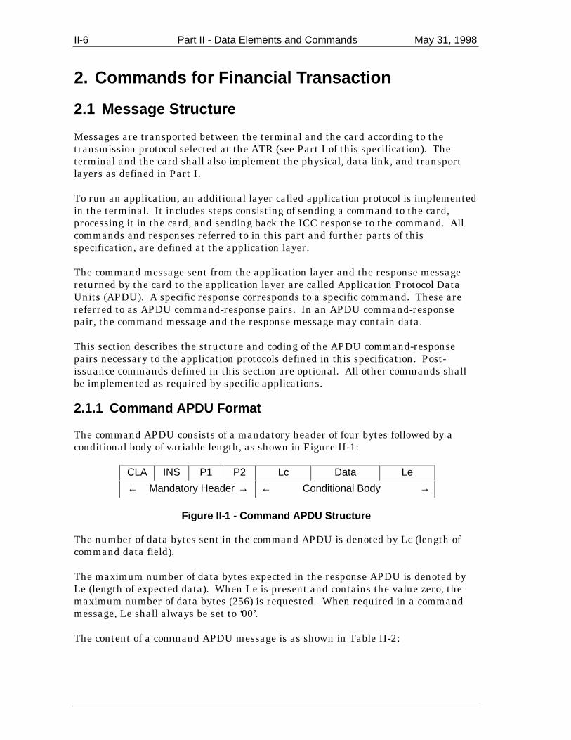
II-6 Part II - Data Elements and Commands May 31, 1998
2. Commands for Financial Transaction
2.1 Message Structure
Messages are transported between the terminal and the card according to thetransmission protocol selected at the ATR (see Part I of this specification). Theterminal and the card shall also implement the physical, data link, and transportlayers as defined in Part I.
To run an application, an additional layer called application protocol is implementedin the terminal. It includes steps consisting of sending a command to the card,processing it in the card, and sending back the ICC response to the command. Allcommands and responses referred to in this part and further parts of thisspecification, are defined at the application layer.
The command message sent from the application layer and the response messagereturned by the card to the application layer are called Application Protocol DataUnits (APDU). A specific response corresponds to a specific command. These arereferred to as APDU command-response pairs. In an APDU command-responsepair, the command message and the response message may contain data.
This section describes the structure and coding of the APDU command-responsepairs necessary to the application protocols defined in this specification. Post-issuance commands defined in this section are optional. All other commands shallbe implemented as required by specific applications.
2.1.1 Command APDU Format
The command APDU consists of a mandatory header of four bytes followed by aconditional body of variable length, as shown in Figure II-1:
CLA INS P1 P2 Lc Data Le
← Mandatory Header → ← Conditional Body →
Figure II-1 - Command APDU Structure
The number of data bytes sent in the command APDU is denoted by Lc (length ofcommand data field).
The maximum number of data bytes expected in the response APDU is denoted byLe (length of expected data). When Le is present and contains the value zero, themaximum number of data bytes (256) is requested. When required in a commandmessage, Le shall always be set to ‘00’.
The content of a command APDU message is as shown in Table II-2:
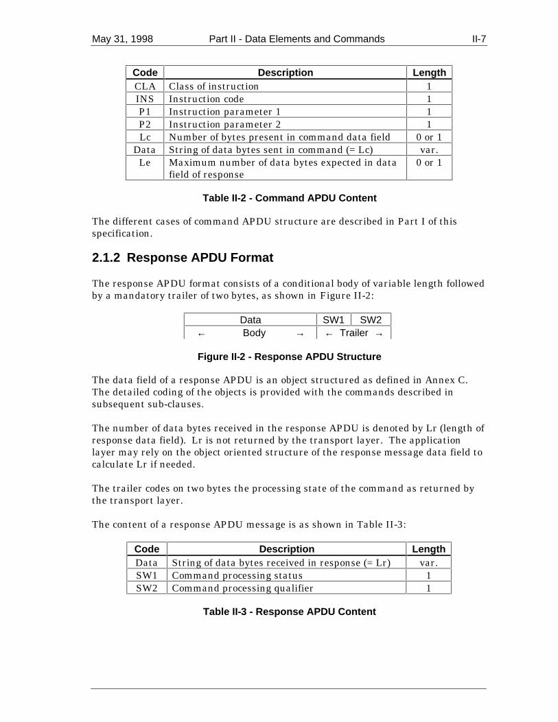
May 31, 1998 Part II - Data Elements and Commands II-7
Code Description LengthCLA Class of instruction 1INS Instruction code 1P1 Instruction parameter 1 1P2 Instruction parameter 2 1Lc Number of bytes present in command data field 0 or 1
Data String of data bytes sent in command (= Lc) var.Le Maximum number of data bytes expected in data
field of response0 or 1
Table II-2 - Command APDU Content
The different cases of command APDU structure are described in Part I of thisspecification.
2.1.2 Response APDU Format
The response APDU format consists of a conditional body of variable length followedby a mandatory trailer of two bytes, as shown in Figure II-2:
Data SW1 SW2← Body → ← Trailer →
Figure II-2 - Response APDU Structure
The data field of a response APDU is an object structured as defined in Annex C.The detailed coding of the objects is provided with the commands described insubsequent sub-clauses.
The number of data bytes received in the response APDU is denoted by Lr (length ofresponse data field). Lr is not returned by the transport layer. The applicationlayer may rely on the object oriented structure of the response message data field tocalculate Lr if needed.
The trailer codes on two bytes the processing state of the command as returned bythe transport layer.
The content of a response APDU message is as shown in Table II-3:
Code Description LengthData String of data bytes received in response (= Lr) var.SW1 Command processing status 1SW2 Command processing qualifier 1
Table II-3 - Response APDU Content
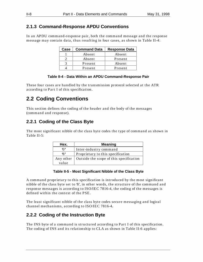
II-8 Part II - Data Elements and Commands May 31, 1998
2.1.3 Command-Response APDU Conventions
In an APDU command-response pair, both the command message and the responsemessage may contain data, thus resulting in four cases, as shown in Table II-4:
Case Command Data Response Data1 Absent Absent2 Absent Present3 Present Absent4 Present Present
Table II-4 - Data Within an APDU Command-Response Pair
These four cases are handled by the transmission protocol selected at the ATRaccording to Part I of this specification.
2.2 Coding Conventions
This section defines the coding of the header and the body of the messages(command and response).
2.2.1 Coding of the Class Byte
The most significant nibble of the class byte codes the type of command as shown inTable II-5:
Hex. Meaning‘0’ Inter-industry command‘8’ Proprietary to this specification
Any othervalue
Outside the scope of this specification
Table II-5 - Most Significant Nibble of the Class Byte
A command proprietary to this specification is introduced by the most significantnibble of the class byte set to ‘8’, in other words, the structure of the command andresponse messages is according to ISO/IEC 7816-4, the coding of the messages isdefined within the context of the PSE.
The least significant nibble of the class byte codes secure messaging and logicalchannel mechanisms, according to ISO/IEC 7816-4.
2.2.2 Coding of the Instruction Byte
The INS byte of a command is structured according to Part I of this specification.The coding of INS and its relationship to CLA as shown in Table II-6 applies:

May 31, 1998 Part II - Data Elements and Commands II-9
CLA INS Meaning‘8x’ ‘1E’ APPLICATION BLOCK‘8x’ ‘18’ APPLICATION UNBLOCK‘8x’ ‘16’ CARD BLOCK‘0x’ ‘82’ EXTERNAL AUTHENTICATE‘8x’ ‘AE’ GENERATE APPLICATION CRYPTOGRAM‘0x’ ‘84’ GET CHALLENGE‘8x’ ‘CA’ GET DATA‘8x’ ‘A8’ GET PROCESSING OPTIONS‘0x’ ‘88’ INTERNAL AUTHENTICATE‘8x’ ‘24’ PERSONAL IDENTIFICATION NUMBER (PIN)
CHANGE/UNBLOCK‘0x’ ‘B2’ READ RECORD‘0x’ ‘A4’ SELECT‘0x’ ‘20’ VERIFY‘8x’ ‘Dx’ RFU for the payment systems‘8x’ ‘Ex’ RFU for the payment systems‘9x’ ‘xx’ RFU for manufacturers for proprietary INS coding‘Ex’ ‘xx’ RFU for issuers for proprietary INS coding
Table II-6 - Coding of the Instruction Byte
Note: Additional INS codes may be assigned in the future in the PSE context using the class ‘8x’. Itis strongly recommended not to define proprietary commands in the class ‘8x’ when they are to beused in the PSE context, so that collision is avoided.
2.2.3 Coding of Parameter Bytes
The parameter bytes P1 P2 may have any value. If not used, a parameter byte hasthe value ‘00’.
2.2.4 Coding of Data Field Bytes
When present, an APDU command message data field consists of a string of dataelements.
When present, an APDU response data field consists of a data object or a string ofdata objects encapsulated in a template according to Annex C.
2.2.5 Coding of the Status Bytes
The status bytes SW1 SW2 are returned by the transport layer to the applicationlayer in any response message and denote the processing state of the command. Thecoding of the status words is structured according to Figure II-3:

II-10 Part II - Data Elements and Commands May 31, 1998
SW1 SW2
Process Completed Process Aborted
Execution
‘65xx’‘64xx’‘63xx’‘62xx’
Warning
‘61xx’‘9000’
‘67xx’ to‘6Fxx’
Normal Checking
Figure II-3 - Structural Scheme of Status Bytes
Coding of SW1 SW2 is as shown in Table II-7 for those status bytes for which theICC Application Specification for Payment Systems requires the card to returncertain status bytes in response to a specific condition. The card may generatestatus bytes not listed in this table for error and warning conditions not specified inthe ICC Application Specification for Payment Systems.
SW1 SW2 MeaningNormal processing
‘90’ ‘00’ Process completed (any other value for SW2 is RFU)Warning processing
‘62’ ‘83’ State of non-volatile memory unchanged; selected file invalidated‘63’ ‘00’ State of non-volatile memory changed; authentication failed‘63’ ‘Cx’ State of non-volatile memory changed; counter provided by ‘x’ (from 0-15)
Checking errors‘69’ ‘83’ Command not allowed; authentication method blocked‘69’ ‘84’ Command not allowed; referenced data invalidated‘69’ ‘85’ Command not allowed; conditions of use not satisfied‘6A’ ‘81’ Wrong parameter(s) P1 P2; function not supported‘6A’ ‘82’ Wrong parameter(s) P1 P2; file not found‘6A’ ‘83’ Wrong parameter(s) P1 P2; record not found
Table II-7 - Coding of Status Bytes SW1 SW2
The following values of SW1 SW2 are described in Part I of this specification as theyapply to the TPDU and are not returned to the APDU:
• ‘61xx’: SW2 indicates the number of response bytes still available. • ‘6Cxx’: Wrong length Le, SW2 indicates the exact length.
SW1 = ‘6x’ or ‘90’ denotes a normal, warning, or error condition coded according toISO/IEC 7816-4.

May 31, 1998 Part II - Data Elements and Commands II-11
When using transmission protocol T=1, for all commands having Le = ‘00’ thesuccessful execution of the command is coded by ’90 00’ or ’61 La’. However, forreadability, both response codes are referenced throughout the text as ’90 00’ only.
Other values of SW1 returned by the ICC are not supported by Part II.
SW1 SW2‘90’ ‘00’ √ √ √ √ √ √ √ √ √ √ √ √ √‘61’ ‘La’ √ √ √ √ √ √‘62’ ‘83’ √1
‘63’ ‘00’ √2
‘63’ ‘Cx’ √3
‘69’ ‘83’ √4
‘69’ ‘84’ √5
‘69’ ‘85’ √6 √7 √8
‘6A’ ‘81’ √9
‘6A’ ‘82’ √10
‘6A’ ‘83’ √11
Table II-8 - Allocation of Status Bytes
The following convention is used in the table:
√ = Indicates normal processing
√x = Allowed response code, for which a dedicated action shall be taken orwhich has a special meaning for an EMV compliant application. Themeaning of the action is explained under the table
= If this response code is returned by the card, the terminal will terminate the transaction
√1 = See section II-2.4.1.1 for appropriate processing.
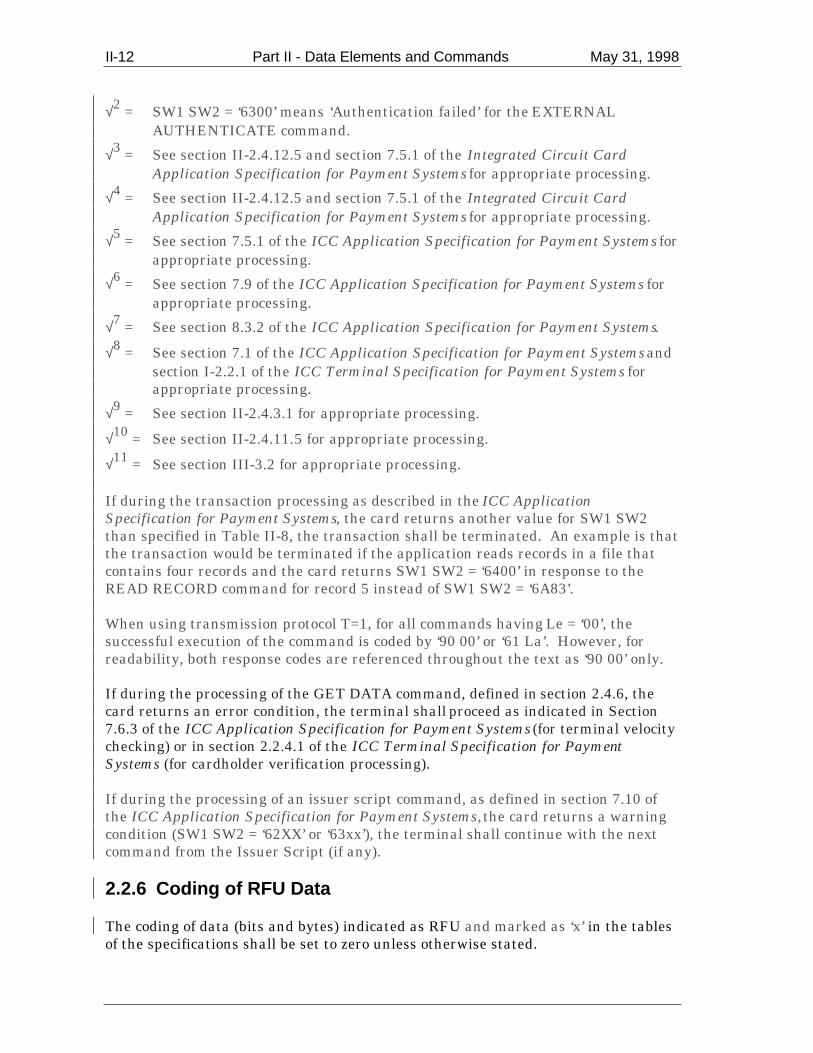
II-12 Part II - Data Elements and Commands May 31, 1998
√2 = SW1 SW2 = ‘6300’ means ‘Authentication failed’ for the EXTERNALAUTHENTICATE command.
√3 = See section II-2.4.12.5 and section 7.5.1 of the Integrated Circuit CardApplication Specification for Payment Systems for appropriate processing.
√4 = See section II-2.4.12.5 and section 7.5.1 of the Integrated Circuit CardApplication Specification for Payment Systems for appropriate processing.
√5 = See section 7.5.1 of the ICC Application Specification for Payment Systems forappropriate processing.
√6 = See section 7.9 of the ICC Application Specification for Payment Systems forappropriate processing.
√7 = See section 8.3.2 of the ICC Application Specification for Payment Systems.
√8 = See section 7.1 of the ICC Application Specification for Payment Systems andsection I-2.2.1 of the ICC Terminal Specification for Payment Systems forappropriate processing.
√9 = See section II-2.4.3.1 for appropriate processing.
√10 = See section II-2.4.11.5 for appropriate processing.
√11 = See section III-3.2 for appropriate processing.
If during the transaction processing as described in the ICC ApplicationSpecification for Payment Systems, the card returns another value for SW1 SW2than specified in Table II-8, the transaction shall be terminated. An example is thatthe transaction would be terminated if the application reads records in a file thatcontains four records and the card returns SW1 SW2 = ‘6400’ in response to theREAD RECORD command for record 5 instead of SW1 SW2 = ‘6A83’.
When using transmission protocol T=1, for all commands having Le = ‘00’, thesuccessful execution of the command is coded by ‘90 00’ or ‘61 La’. However, forreadability, both response codes are referenced throughout the text as ‘90 00’ only.
If during the processing of the GET DATA command, defined in section 2.4.6, thecard returns an error condition, the terminal shall proceed as indicated in Section7.6.3 of the ICC Application Specification for Payment Systems (for terminal velocitychecking) or in section 2.2.4.1 of the ICC Terminal Specification for PaymentSystems (for cardholder verification processing).
If during the processing of an issuer script command, as defined in section 7.10 ofthe ICC Application Specification for Payment Systems, the card returns a warningcondition (SW1 SW2 = ‘62XX’ or ‘63xx’), the terminal shall continue with the nextcommand from the Issuer Script (if any).
2.2.6 Coding of RFU Data
The coding of data (bits and bytes) indicated as RFU and marked as ‘x’ in the tablesof the specifications shall be set to zero unless otherwise stated.

May 31, 1998 Part II - Data Elements and Commands II-13
2.3 Logical Channels
A logical channel establishes and maintains the link between an application in theterminal and an application in the card.
A card may support more than one logical channel but only the basic logical channelis supported by this specification. This limits to one the number of concurrentapplications according to this specification.
2.4 Commands
This section describes the following APDU command-response pairs:
• APPLICATION BLOCK (post-issuance command)• APPLICATION UNBLOCK (post-issuance command)• CARD BLOCK (post-issuance command)• EXTERNAL AUTHENTICATE• GENERATE APPLICATION CRYPTOGRAM• GET CHALLENGE• GET DATA• GET PROCESSING OPTIONS• INTERNAL AUTHENTICATE• PIN CHANGE/UNBLOCK (post-issuance command)• READ RECORD• SELECT• VERIFY
The post-issuance commands shall only be sent using script processing (see the ICCApplication Specification for Payment Systems) and secure messaging as specified inPart IV of this specification.
2.4.1 APPLICATION BLOCK Command-Response APDUs
2.4.1.1 Definition and Scope
The APPLICATION BLOCK command is a post-issuance command that invalidatesthe currently selected application.
Following the successful completion of an APPLICATION BLOCK command:
• An invalidated application shall return the status bytes ‘Selected file invalidated’(SW1 SW2 = ‘6283’) in response to a SELECT command.
• An invalidated application shall return only an AAC as AC in response to a
GENERATE AC command.
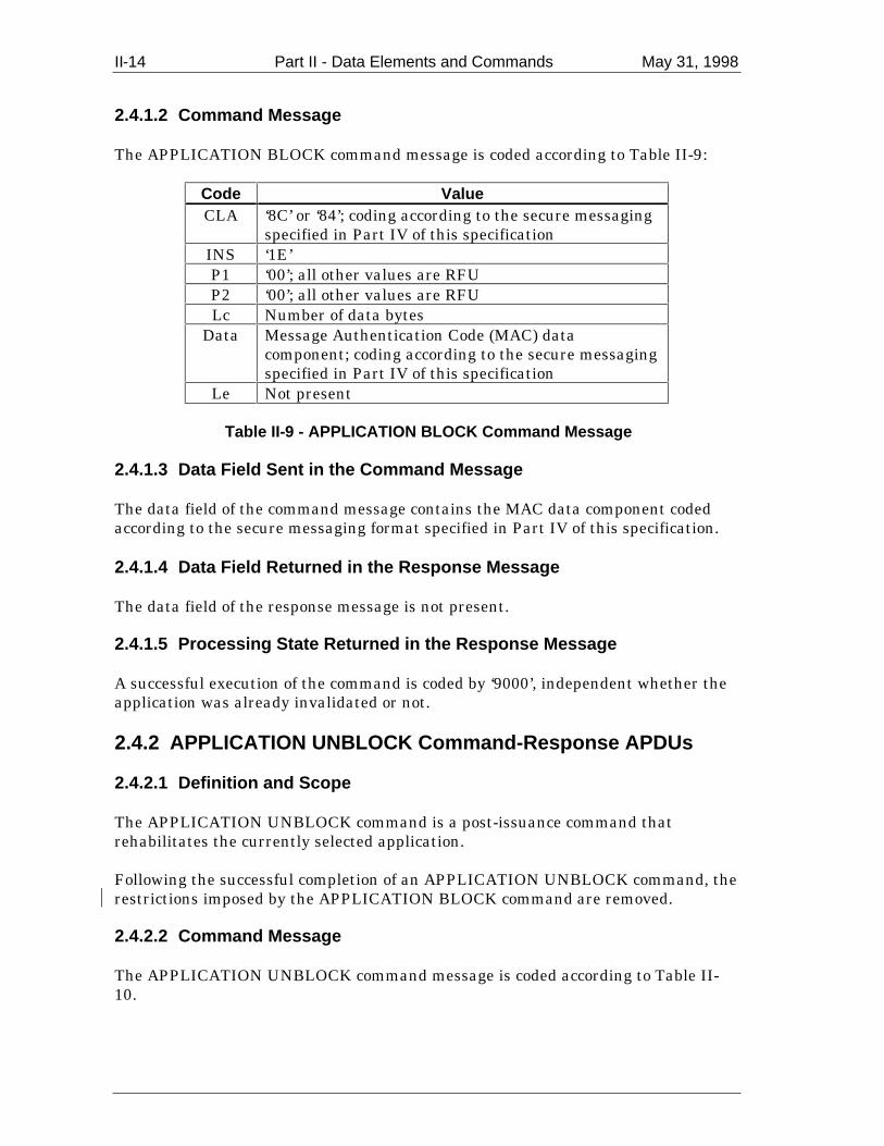
II-14 Part II - Data Elements and Commands May 31, 1998
2.4.1.2 Command Message
The APPLICATION BLOCK command message is coded according to Table II-9:
Code ValueCLA ‘8C’ or ‘84’; coding according to the secure messaging
specified in Part IV of this specificationINS ‘1E’P1 ‘00’; all other values are RFUP2 ‘00’; all other values are RFULc Number of data bytes
Data Message Authentication Code (MAC) datacomponent; coding according to the secure messagingspecified in Part IV of this specification
Le Not present
Table II-9 - APPLICATION BLOCK Command Message
2.4.1.3 Data Field Sent in the Command Message
The data field of the command message contains the MAC data component codedaccording to the secure messaging format specified in Part IV of this specification.
2.4.1.4 Data Field Returned in the Response Message
The data field of the response message is not present.
2.4.1.5 Processing State Returned in the Response Message
A successful execution of the command is coded by ‘9000’, independent whether theapplication was already invalidated or not.
2.4.2 APPLICATION UNBLOCK Command-Response APDUs
2.4.2.1 Definition and Scope
The APPLICATION UNBLOCK command is a post-issuance command thatrehabilitates the currently selected application.
Following the successful completion of an APPLICATION UNBLOCK command, therestrictions imposed by the APPLICATION BLOCK command are removed.
2.4.2.2 Command Message
The APPLICATION UNBLOCK command message is coded according to Table II-10.

May 31, 1998 Part II - Data Elements and Commands II-15
Code ValueCLA ‘8C’ or ‘84’; coding according to the secure messaging
specified in Part IV of this specificationINS ‘18’P1 ‘00’; all other values are RFUP2 ‘00’; all other values are RFULc Number of data bytes
Data MAC data component; coding according to the securemessaging specified in Part IV of this specification
Le Not present
Table II-10 - APPLICATION UNBLOCK Command Message
2.4.2.3 Data Field Sent in the Command Message
The data field of the command message contains the MAC data component codedaccording to the secure messaging format specified in Part IV of this specification.
2.4.2.4 Data Field Returned in the Response Message
The data field of the response message is not present.
2.4.2.5 Processing State Returned in the Response Message
A successful execution of the command is coded by ‘9000’, independent whether theapplication was invalidated or not.
2.4.3 CARD BLOCK Command-Response APDUs
2.4.3.1 Definition and Scope
The CARD BLOCK command is a post-issuance command that permanentlydisables all applications in the ICC.
The CARD BLOCK command shall disable all applications in the ICC, includingapplications that may be selected implicitly.
Following the successful completion of a CARD BLOCK command, all subsequentSELECT commands shall return the status bytes ‘Function not supported’ (SW1SW2 = ‘6A81’) and perform no other action.
2.4.3.2 Command Message
The CARD BLOCK command message is coded according to Table II-11.

II-16 Part II - Data Elements and Commands May 31, 1998
Code ValueCLA ‘8C’ or ‘84’; coding according to the secure messaging
specified in Part IV of this specificationINS ‘16’P1 ‘00’; all other values are RFUP2 ‘00’; all other values are RFULc Number of data bytes
Data MAC data component; coding according to the securemessaging specified in Part IV of this specification
Le Not present
Table II-11 - CARD BLOCK Command Message
2.4.3.3 Data Field Sent in the Command Message
The data field of the command message contains the MAC data component codedaccording to the secure messaging format specified in Part IV of this specification.
2.4.3.4 Data Field Returned in the Response Message
The data field of the response message is not present.
2.4.3.5 Processing State Returned in the Response Message
A successful execution of the command is coded by ‘9000’, independent of whetherthe card was already blocked or not.
2.4.4 EXTERNAL AUTHENTICATE Command-Response APDUs
2.4.4.1 Definition and Scope
The EXTERNAL AUTHENTICATE command asks the application in the ICC toverify a cryptogram.
The response from the ICC consists of returning the processing state of thecommand.
2.4.4.2 Command Message
The EXTERNAL AUTHENTICATE command message is coded according to TableII-12:

May 31, 1998 Part II - Data Elements and Commands II-17
Code ValueCLA ‘00’INS ‘82’P1 ‘00’P2 ‘00’Lc 8-16
Data Issuer Authentication DataLe Not present
Table II-12 - EXTERNAL AUTHENTICATE Command Message
The reference of the algorithm (P1) of the EXTERNAL AUTHENTICATE commandis coded ‘00’, which means that no information is given. The reference of thealgorithm is known either before issuing the command or is provided in the datafield.
2.4.4.3 Data Field Sent in the Command Message
The data field of the command message contains the value field of tag ‘91’ coded asfollows:
• Mandatory first 8 bytes containing the cryptogram.
• Optional additional 1-8 bytes are proprietary.
2.4.4.4 Data Field Returned in the Response Message
The data field of the response message is not present.
2.4.4.5 Processing State Returned in the Response Message
A successful execution of the command is coded by ‘9000’.
2.4.5 GENERATE APPLICATION CRYPTOGRAM Command-Response APDUs
2.4.5.1 Definition and Scope
The GENERATE AC command sends transaction-related data to the ICC, whichcomputes and returns a cryptogram. This cryptogram shall either be an ApplicationCryptogram (AC) as specified in this specification or a proprietary cryptogram. Inboth cases, the cryptogram shall be of a type specified in Table II-13 (for moredetails, see the ICC Application Specification for Payment Systems).

II-18 Part II - Data Elements and Commands May 31, 1998
Type MeaningApplication AuthenticationCryptogram (AAC)
Transaction declined
Application Authorisation Referral(AAR)
Referral requested by the card
Authorisation Request Cryptogram(ARQC)
Online authorisation requested
Transaction Certificate(TC)
Transaction approved
Table II-13 - GENERATE AC Cryptogram Types
The cryptogram returned by the ICC may differ from that requested in thecommand message according to an internal process in the ICC (as described in theICC Application Specification for Payment Systems).
2.4.5.2 Command Message
The GENERATE AC command message is coded according to Table II-14:
Code ValueCLA ‘80’INS ‘AE’P1 Reference control parameter
(see Table II-15)P2 ‘00’Lc var.
Data Transaction-related dataLe ‘00’
Table II-14 - GENERATE AC Command Message
The reference control parameter of the GENERATE AC command is coded as shownin Table II-15:
b8 b7 b6 b5 b4 b3 b2 b1 Meaning0 0 AAC0 1 TC1 0 ARQC1 1 RFU
x x x x x x RFU
Table II-15 - GENERATE AC Reference Control Parameter
2.4.5.3 Data Field Sent in the Command Message
The content of the data field of the command message is coded according to the rulesfor the data object list as defined in Section II-1.4.
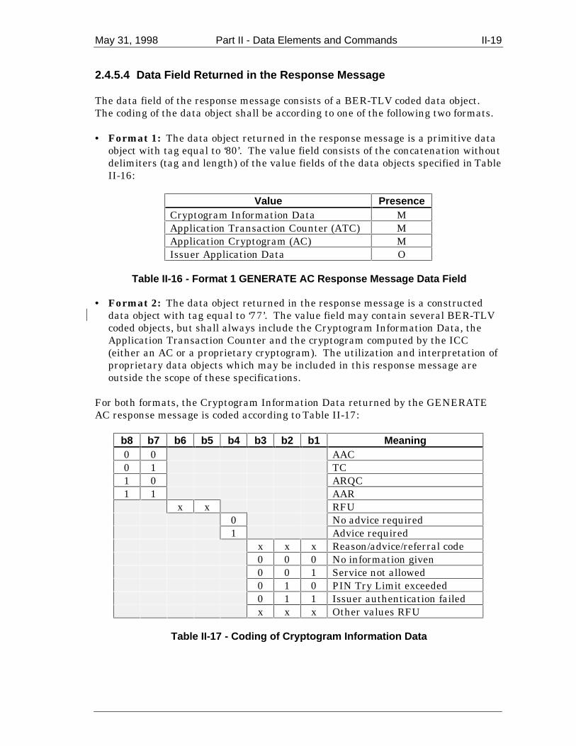
May 31, 1998 Part II - Data Elements and Commands II-19
2.4.5.4 Data Field Returned in the Response Message
The data field of the response message consists of a BER-TLV coded data object.The coding of the data object shall be according to one of the following two formats.
• Format 1: The data object returned in the response message is a primitive dataobject with tag equal to ‘80’. The value field consists of the concatenation withoutdelimiters (tag and length) of the value fields of the data objects specified in TableII-16:
Value PresenceCryptogram Information Data MApplication Transaction Counter (ATC) MApplication Cryptogram (AC) MIssuer Application Data O
Table II-16 - Format 1 GENERATE AC Response Message Data Field
• Format 2: The data object returned in the response message is a constructeddata object with tag equal to ‘77’. The value field may contain several BER-TLVcoded objects, but shall always include the Cryptogram Information Data, theApplication Transaction Counter and the cryptogram computed by the ICC(either an AC or a proprietary cryptogram). The utilization and interpretation ofproprietary data objects which may be included in this response message areoutside the scope of these specifications.
For both formats, the Cryptogram Information Data returned by the GENERATEAC response message is coded according to Table II-17:
b8 b7 b6 b5 b4 b3 b2 b1 Meaning0 0 AAC0 1 TC1 0 ARQC1 1 AAR
x x RFU0 No advice required1 Advice required
x x x Reason/advice/referral code0 0 0 No information given0 0 1 Service not allowed0 1 0 PIN Try Limit exceeded0 1 1 Issuer authentication failedx x x Other values RFU
Table II-17 - Coding of Cryptogram Information Data

II-20 Part II - Data Elements and Commands May 31, 1998
2.4.5.5 Processing State Returned in the Response Message
A successful execution of the command is coded by ‘9000’.
2.4.6 GET DATA Command-Response APDUs
2.4.6.1 Definition and Scope
The GET DATA command is used to retrieve a primitive data object notencapsulated in a record within the current application.
The usage of the GET DATA command in this specification is limited to the retrievalof the primitive data objects ATC (tag ‘9F36’), Last Online ATC Register (tag ‘9F13’),or PIN Try Counter (tag ‘9F17’) defined in Annex B, Table B-1 that are interpretedby the application in the ICC.
2.4.6.2 Command Message
The GET DATA command message is coded according to Table II-18:
Code ValueCLA ‘80’INS ‘CA’
P1 P2 ‘9F36’, ‘9F13’, or ‘9F17’Lc Not present
Data Not presentLe ‘00’
Table II-18 - GET DATA Command Message
2.4.6.3 Data Field Sent in the Command Message
The data field of the command message is not present.
2.4.6.4 Data Field Returned in the Response Message
The data field of the response message contains the primitive data object referred toin P1 P2 of the command message (in other words, including its tag and its length).
2.4.6.5 Processing State Returned in the Response Message
A successful execution of the command is coded by ‘9000’.

May 31, 1998 Part II - Data Elements and Commands II-21
2.4.7 GET PROCESSING OPTIONS Command-Response APDUs
2.4.7.1 Definition and Scope
The GET PROCESSING OPTIONS command initiates the transaction within theICC.
The response from the ICC consists of returning the Application Interchange Profile(AIP) and the Application File Locator (AFL).
2.4.7.2 Command Message
The GET PROCESSING OPTIONS command message is coded according to TableII-19:
Code ValueCLA ‘80’INS ‘A8’P1 ‘00’; all other values are RFUP2 ‘00’; all other values are RFULc var.
Data Processing Options Data Object List(PDOL) related data
Le ‘00’
Table II-19 - GET PROCESSING OPTIONS Command Message
2.4.7.3 Data Field Sent in the Command Message
The data field of the command message is a data object coded according to theProcessing Options Data Object List (PDOL) provided by the ICC, as defined insection II-1.4, and is introduced by the tag ‘83’. When the data object list is notprovided by the ICC, the length field of the template is set to zero. Otherwise, thelength field of the template is the total length of the value fields of the data objectstransmitted to the ICC.
2.4.7.4 Data Field Returned in the Response Message
The data field of the response message consists of a BER-TLV coded data object.The coding of the data object shall be according to one of the following two formats.
• Format 1: The data object returned in the response message is a primitive dataobject with tag equal to ‘80’. The value field consists of the concatenation withoutdelimiters (tag and length) of the value fields of the Application InterchangeProfile (AIP) and the Application File Locator (AFL). The coding of the dataobject returned in the response message is shown in Table II-20:

II-22 Part II - Data Elements and Commands May 31, 1998
‘80’ Length Application Interchange Profile AFL
Table II-20 - Format 1 GET PROCESSING OPTIONS Response Message Data Field
• Format 2: The data object returned in the response message is a constructeddata object with tag equal to ‘77’. The value field may contain several BER-TLVcoded objects, but shall always include the AIP and the AFL. The utilization andinterpretation of proprietary data objects which may be included in this responsemessage are outside the scope of these specifications.
The AIP specifies the application functions that are supported by the application inthe ICC and is coded according to the ICC Application Specification for PaymentSystems.
The AFL consists of the list without delimiters of files and related records that shallbe read according to the ICC Application Specification for Payment Systems for thecurrently selected application.
2.4.7.5 Processing State Returned in the Response Message
A successful execution of the command is coded by ‘9000’.
2.4.8 INTERNAL AUTHENTICATE Command-Response APDUs
2.4.8.1 Definition and Scope
The INTERNAL AUTHENTICATE command initiates the computation of theSigned Dynamic Application Data by the card using the challenge data sent fromthe IFD and data and a relevant private key stored in the card.
The response from the ICC consists of returning the Signed Dynamic ApplicationData to the terminal.
2.4.8.2 Command Message
The INTERNAL AUTHENTICATE command message is coded according to TableII-21:
Code ValueCLA ‘00’INS ‘88’P1 ‘00’P2 ‘00’Lc Length of authentication-related data
Data Authentication-related dataLe ‘00’
Table II-21 - INTERNAL AUTHENTICATE Command Message

May 31, 1998 Part II - Data Elements and Commands II-23
The reference of the algorithm (P1) of the INTERNAL AUTHENTICATE commandis coded ‘00’, which means that no information is given. The reference of thealgorithm is known either before issuing the command or is provided in the datafield.
2.4.8.3 Data Field Sent in the Command Message
The data field of the command message contains the authentication-related dataproprietary to an application. It is coded according to the Dynamic DataAuthentication Data Object List (DDOL) as defined in Part IV of this specification.
2.4.8.4 Data Field Returned in the Response Message
The data field of the response message consists of a BER-TLV coded data object.The coding of the data object shall be according to one of the following two formats.
• Format 1: The data object returned in the response message is a primitive dataobject with tag equal to ‘80’. The value field consists of the value field of theSigned Dynamic Application Data as specified in Part IV of this specification.
• Format 2: The data object returned in the response message is a constructed
data object with tag equal to ‘77’. The value field may contain several BER-TLVcoded objects, but shall always include the Signed Dynamic Application Data asspecified in Part IV of this specification. The utilization and interpretation ofproprietary data objects which may be included in this response message areoutside the scope of these specifications.
2.4.8.5 Processing State Returned in the Response Message
A successful execution of the command is coded by ‘9000’’.
2.4.9 PIN CHANGE/UNBLOCK Command-Response APDUs
2.4.9.1 Definition and Scope
The PIN CHANGE/UNBLOCK command is a post-issuance command. Its purposeis to provide the issuer the capability either to unblock the PIN or to simultaneouslychange and unblock the reference PIN.
Upon successful completion of the PIN CHANGE/UNBLOCK command, the cardshall perform the following functions:
• The value of the PIN Try Counter shall be reset to the value of the PIN TryLimit.
• If requested, the value of the reference PIN shall be set to the new PIN value.

II-24 Part II - Data Elements and Commands May 31, 1998
The PIN data transmitted in the command, if present, shall be enciphered forconfidentiality.
Note: The reference PIN, which is stored within the card, is the one that is associated wi th theapplication, and which the card uses to the check the Transaction PIN Data transmitted within theVERIFY command.
2.4.9.2 Command Message
The PIN CHANGE/UNBLOCK command message is coded according to Table II-22.
Code ValueCLA ‘8C’ or ‘84’; coding according to the secure
messaging specified in Part IV of thisspecification
INS ‘24’P1 ‘00’P2 ‘00’, ‘01’, or ‘02’Lc Number of data bytes
Data Enciphered PIN data component, if present,and MAC data component; coding according tothe secure messaging specified in Part IV of thisspecification
Le Not present
Table II-22 - PIN CHANGE/UNBLOCK Command Message
P2: If P2 is equal to ‘00’, the reference PIN is unblocked and the PIN Try Counteris reset to the PIN Try Limit. There is no PIN update, since the PINCHANGE/UNBLOCK command does not contain a new PIN value.
Any other value of P2 allowing PIN unblocking and/or PIN changing is out ofthe scope of this specification and shall be described for each payment systemindividually.
2.4.9.3 Data Field Sent in the Command Message
The data field of the command message contains the PIN data component, ifpresent, followed by the MAC data component coded according to the securemessaging format specified in Part IV of this specification.
2.4.9.4 Data Field Returned in the Response Message
The data field of the response message is not present.
2.4.9.5 Processing State Returned in the Response Message
A successful execution of the command is coded by ‘9000’.

May 31, 1998 Part II - Data Elements and Commands II-25
2.4.10 READ RECORD Command-Response APDUs
2.4.10.1 Definition and Scope
The READ RECORD command reads a file record in a linear file.
The response from the ICC consists of returning the record.
2.4.10.2 Command Message
The READ RECORD command message is coded according to Table II-23:
Code ValueCLA ‘00’INS ‘B2’P1 Record numberP2 Reference control parameter (see
Table II-24)Lc Not present
Data Not presentLe ‘00’
Table II-23 - READ RECORD Command Message
Table II-24 defines the reference control parameter of the command message:
b8 b7 b6 b5 b4 b3 b2 b1 Meaningx x x x x SFI
1 0 0 P1 is a record number
Table II-24 - READ RECORD Command Reference Control Parameter
2.4.10.3 Data Field Sent in the Command Message
The data field of the command message is not present.
2.4.10.4 Data Field Returned in the Response Message
The data field of the response message of any successful READ RECORD commandcontains the record read. For SFIs in the range 1-10, the record is a BER-TLVconstructed data object as defined in Annex C and coded as shown in Table II-25:
‘70’ Length Record Template
Table II-25 - READ RECORD Response Message Data Field
The response message to READ RECORD for SFIs outside the range 1-10 is outsidethe scope of this specification.

II-26 Part II - Data Elements and Commands May 31, 1998
2.4.10.5 Processing State Returned in the Response Message
A successful execution of the command is coded by ‘9000’.
2.4.11 SELECT Command-Response APDUs
2.4.11.1 Definition and Scope
The SELECT command is used to select the ICC PSE, DDF, or ADF correspondingto the submitted file name or AID. The selection of an application is described inPart III of this specification.
A successful execution of the command sets the path to the PSE, DDF, or ADF.
Subsequent commands apply to AEFs associated to the selected PSE, DDF, or ADFusing SFIs.
The response from the ICC consists of returning the FCI.
2.4.11.2 Command Message
The SELECT command message is coded according to Table II-26:
Code ValueCLA ‘00’INS ‘A4’P1 Reference control parameter (see
Table II-27)P2 Selection options (see Table II-28)Lc ‘05’-‘10’
Data File nameLe ‘00’
Table II-26 - SELECT Command Message
Table II-27 defines the reference control parameter of the SELECT commandmessage:
b8 b7 b6 b5 b4 b3 b2 b1 Meaning0 0 0 0 0
1 Select by name0 0
Table II-27 - SELECT Command Reference Control Parameter
Table II-27 defines the selection options P2 of the SELECT command message:

May 31, 1998 Part II - Data Elements and Commands II-27
b8 b7 b6 b5 b4 b3 b2 b1 Meaning0 0 First or only
occurrence1 0 Next occurrence
Table II-28 - SELECT Command Options Parameter
2.4.11.3 Data Field Sent in the Command Message
The data field of the command message contains the PSE name or the DF name orthe AID to be selected.
2.4.11.4 Data Field Returned in the Response Message
The data field of the response message contains the FCI specific to the selected PSE,DDF, or ADF. The tags defined in Table II-29 to Table II-31 apply to thisspecification. Additional tags returned in the FCI that are not described in thisspecification shall be ignored.
Table II-29 defines the FCI returned by a successful selection of the PSE:
Tag Value Presence‘6F’ FCI Template M‘84’ DF Name M‘A5’ FCI Proprietary Template M‘88’ SFI of the directory elementary file M
‘5F2D’ Language Preference O‘9F11’ Issuer Code Table Index O‘BF0C’ FCI Issuer Discretionary Data O
Table II-29 - SELECT Response Message Data Field (FCI) of the PSE
Table II-30 defines the FCI returned by a successful selection of a DDF:
Tag Value Presence‘6F’ FCI Template M‘84’ DF Name M‘A5’ FCI Proprietary Template M‘88’ SFI of the directory elementary file M
‘BF0C’ FCI Issuer Discretionary Data O
Table II-30 - SELECT Response Message Data Field (FCI) of a DDF
Table II-31 defines the FCI returned by a successful selection of an ADF:

II-28 Part II - Data Elements and Commands May 31, 1998
Tag Value Presence‘6F’ FCI Template M‘84’ DF Name M‘A5’ FCI Proprietary Template M‘50’ Application Label O‘87’ Application Priority Indicator O
‘9F38’ PDOL O‘5F2D’ Language Preference O‘9F11’ Issuer Code Table Index O‘9F12’ Application Preferred Name O‘BF0C’ FCI Issuer Discretionary Data O
Table II-31 - SELECT Response Message Data Field (FCI) of an ADF
2.4.11.5 Processing State Returned in the Response Message
A successful execution of the command is coded by ‘9000’.
ICC support for the selection of a DF file using only a partial DF name is notmandatory. However, if the ICC does support partial name selection, it shall complywith the following:
If the SELECT command having the coding of b2 and b1 set to ‘10’ (next) is repeatedwith the same partial DF name by the terminal after a DF file has been successfullyselected, the card shall select a different DF file matching the partial name, if suchanother DF file exists. Repeated issuing of the same command with no interveningapplication level commands shall retrieve all such files, but shall retrieve no filetwice. After all matching DF files have been selected, repeating the same commandagain shall result in no file being selected, and the card shall respond with SW1SW2 = ‘6A82’ (file not found).
2.4.12 VERIFY Command-Response APDUs
2.4.12.1 Definition and Scope
The VERIFY command initiates in the ICC the comparison of the Transaction PINData sent in the data field of the command with the reference PIN data associatedwith the application. The manner in which the comparison is performed isproprietary to the application in the ICC.
The VERIFY command applies when the Cardholder Verification Method (CVM)chosen from the CVM List is an offline PIN, as described in the ICC ApplicationSpecification for Payment Systems.
2.4.12.2 Command Message
The VERIFY command message is coded according to Table II-32:

May 31, 1998 Part II - Data Elements and Commands II-29
Code ValueCLA ‘00’INS ‘20’P1 ‘00’P2 Qualifier of the reference data (see Table II-33)Lc var.
Data Transaction PIN DataLe Not present
Table II-32 - VERIFY Command Message
Table II-33 defines the qualifier of the reference data (P2):
b8 b7 b6 b5 b4 b3 b2 b1 Meaning0 0 0 0 0 0 0 0 As defined in ISO/IEC 7816-41 0 0 0 0 0 0 0 Plaintext PIN, format as defined below1 0 0 0 0 x x x RFU for this specification1 0 0 0 1 0 0 0 Enciphered PIN, format as defined in
section IV-41 0 0 0 1 0 x x RFU for this specification1 0 0 0 1 1 x x RFU for the individual payment
systems1 0 0 1 x x x x RFU for the issuer
Table II-33 - VERIFY Command Qualifier of Reference Data (P2)
The processing of the VERIFY command in the ICC will be defined in combinationwith the CVM rules as specified in the ICC Application Specification for PaymentSystems.
The plaintext offline PIN block shall be formatted as follows:
C N P P P P P/F P/F P/F P/F P/F P/F P/F P/F F F
where
Name ValueC Control field Binary 2 (hex. 0010)N PIN length 4-bit binary number with permissible values of hex.
0100 to hex. 1100P PIN digit 4-bit field with permissible values of hex. 0000 to
hex. 1001P/F PIN/filler Determined by PIN lengthF Filler 4-bit binary number with value of hex. 1111
P2 = ‘00’ indicates that no particular qualifier is used. The processing of theVERIFY command in the ICC should know how to find the PIN dataunambiguously.

II-30 Part II - Data Elements and Commands May 31, 1998
2.4.12.3 Data Field Sent in the Command Message
The data field of the command message contains the value field of tag ‘99’.
2.4.12.4 Data Field Returned in the Response Message
The data field of the response message is not present.
2.4.12.5 Processing State Returned in the Response Message
A successful execution of the command is coded by ‘9000’.
When for the currently selected application the comparison between the TransactionPIN Data and the reference PIN data performed by the VERIFY command fails, theICC shall return SW2 = ‘Cx’, where ‘x’ represents the number of retries still possible.When the card returns ‘C0’, no more retries are left, and the CVM shall be blocked.Any subsequent VERIFY command applied in the context of that application shallthen fail with SW1 SW2 = ‘6983’.
2.4.13 GET CHALLENGE Command-Response APDUs
2.4.13.1 Definition and Scope
The GET CHALLENGE ommand is used to obtain an unpredictable number fromthe ICC for use in a security-related procedure.
The challenge shall be valid only for the next issued command.
2.4.13.2 Command Message
The GET CHALLENGE command message is coded according to Table II-32:
Code ValueCLA ‘00’INS ‘84’P1 ‘00’P2 ‘00’Lc Not present
Data Not presentLe ’00’
Table II-34 - GET CHALLENGE Command Message
May 31, 1998 Part II - Data Elements and Commands II-31
2.4.13.3 Data Field Sent in the Command Message
The data field of the command message is not present.
2.4.13.4 Data Field Returned in the Response Message
The data field of the response message contains an 8-byte unpredictable numbergenerated by the ICC.
2.4.13.5 Processing State Returned in the Response Message
A successful execution of the command is coded by ‘9000’.


Part IIIApplication Selection


May 31, 1998 Part III - Application Selection III-1
1. Overview of Application Selection
Application selection is the process performed immediately after the reset of the cardand prior to the first application function.
This section describes the application selection process from the standpoint of boththe card and the terminal. The logical structure of data and files within the cardthat are required for the process is specified, after which the terminal logic using thecard structure is described.
The ICC and the terminal may support and use implicit selection, but it is notdescribed here as it is not useful in an interchange environment.
The application selection process described in this section is the process by which theterminal uses data in the ICC according to protocols defined herein to determine theterminal program and the ICC application to be used in processing a transaction.The process is described in two steps:
1. Create a list of ICC applications that are supported by the terminal. (This list isreferred to below using the name ‘candidate list.’) This process is described insection III-3.
2. Select the application to be run from the list generated above. This process isdescribed in section III-4.
It is the intent of this part of the specification to describe the necessary informationin the card and two terminal selection algorithms that yield the correct results.Other terminal selection algorithms that yield the same results are permitted inplace of the selection algorithms described here.
A payment system application is comprised of the following:
• A set of files in the ICC providing data customised by the issuer.• Data in the terminal provided by the acquirer or the merchant.• An application protocol agreed upon by both the ICC and the terminal.
Applications are uniquely identified by AIDs conforming to ISO/IEC 7816-5 (seesection III-2.13).
The techniques chosen by the payment systems and described herein are designed tomeet the following key objectives:
• Ability to work with ICCs with a wide range of capabilities.
• Ability for terminals with a wide range of capabilities to work with all ICCssupporting payment system applications according to this specification.

III-2 Part III - Application Selection May 31, 1998
• Conformance with ISO standards.
• Ability of ICCs to support multiple applications, not all of which need to bepayment system applications.
• Ability for ICCs to provide multiple sets of applications to be supported by asingle terminal program. (For example, a card may contain multiple credit/debitapplications, each representing a different type or level of service or a differentaccount).
• As far as possible, provide the capability for applications conforming with thisspecification to co-reside on cards with presently existing applications.
• Minimum overhead in storage and processing.
• Ability for the issuer to optimise the selection process.
The set of data that the ICC contains in support of a given application is defined by anADF selected by the terminal using a SELECT command and an AFL returned by theICC in response to a GET PROCESSING OPTIONS command.
2. Data in the ICC Used for Application Selection
2.1 Coding of Payment System Application Identifier
The structure of the AID is according to ISO/IEC 7816-5 and consists of two parts:
1. A Registered Application Provider Identifier (RID) of 5 bytes, unique to anapplication provider and assigned according to ISO/IEC 7816-5.
2. An optional field assigned by the application provider of up to 11 bytes. This fieldis known as a Proprietary Application Identifier Extension (PIX) and may containany 0-11 byte value specified by the provider. The meaning of this field is definedonly for the specific RID and need not be unique across different RIDs.
Additional ADFs defined under the control of other application providers may bepresent in the ICC but shall avoid duplicating the range of RIDs assigned topayment systems. Compliance with ISO/IEC 7816-5 will assure this avoidance.
2.2 Structure of the Payment Systems Environment
The Payment Systems Environment (PSE) begins with a Directory Definition File(DDF) given the name ‘1PAY.SYS.DDF01’. The presence of this DDF in the ICC isoptional but, if present, shall comply with this specification. If it is present, thisDDF is mapped onto a DF within the card, which may or may not be the MF. Aswith all DDFs, this DDF shall contain a Payment Systems Directory. The FCI ofthis DDF shall contain at least the information defined for all DDFs in Part II and,

May 31, 1998 Part III - Application Selection III-3
optionally, the Language Preference (tag ‘5F2D’) and the Issuer Code Table Index(tag ‘9F11’).
The Language Preference and Issuer Code Table Index are optional data objectsthat may occur in two places: the FCI of the PSE and the FCI of ADF files. If thesedata objects exist, they shall exist in both places, and shall have the identical valuesin all occurrences. The terminal may use the values from either location.9
The directory attached to this initial DDF contains entries for ADFs that areformatted according to this specification, although the applications defined by thoseADFs may or may not conform to this specification. The directory may also containentries for other payment system’s DDFs, which shall conform to this specification.
The directory is not required to have entries for all DDFs and ADFs in the card, andfollowing the chain of DDFs may not reveal all applications supported by the card.However, if the PSE exists, only applications that are revealed by following thechain of DDFs beginning with the initial directory can be assured of internationalinteroperability.
See Annex D for examples of the internal logic structure of an ICC containing thePSE.
2.3 Coding of a Payment System’s Directory
A Payment System’s Directory (hereafter referred to as simply a directory) is a linearEF file identified by an SFI in the range 1 to 10. The SFI for the directory is containedin the FCI of the DDF to which the directory is attached. The directory is read usingthe READ RECORD command as defined in Part II of this specification. A record mayhave several entries, but a single entry shall always be encapsulated in a single record.
Records in the Payment Systems Directory conform to all other requirements in thisspecification. Each record is a constructed data object, and the value field iscomprised of one or more directory entries as described below. Each record isformatted as shown in Table III-1:
9 A terminal building a candidate list using the process described in section 3.2 willencounter the values specified in the FCI of the PSE and will not see the valuesspecified in the FCI of the ADF until the application to be run has been chosen. Aterminal building the candidate list using the process described in section 3.3 willencounter the values specified in the FCI of the ADFs. To ensure consistentinterface to the cardholder, the values must be the same.

III-4 Part III - Application Selection May 31, 1998
Tag‘70’
DataLength(L)
Tag‘61’
Lengthofdirectoryentry 1
Directoryentry 1(ADF orDDF)
... Tag‘61’
Lengthofdirectoryentry n
Directoryentry n(ADF orDDF)
Table III-1 - PSE Directory Record Format
Each entry in a Payment Systems Directory is the value field of an ApplicationTemplate (tag ‘61’) and contains the information according to Table III-2 or Table III-3.
If any data objects that are not encapsulated in an Application Template (tag ‘61’)appear in the directory record or any data objects other than those listed in Table III-2or Table III-3 appear in a directory entry they shall be ignored.
Tag Length Value Presence‘9D’ 5-16 DDF Name M‘73’ var. Directory Discretionary Template O10
Table III-2 - DDF Directory Entry Format
Tag Length Value Presence‘4F’ 5-16 ADF Name (AID) M‘50’ 1-16 Application Label M
‘9F12’ 1-16 Application Preferred Name O‘87’ 1 Application Priority Indicator (see Table
III-)O
‘73’ var. Directory Discretionary Template O10
Table III-3 - ADF Directory Entry Format
b8 b7-b5 b4-b1 Definition1 Application cannot be selected without confirmation of
cardholder0 Application may be selected without confirmation of
cardholderxxx RFU
0000 No priority assignedxxxx(except0000)
Order in which the application is to be listed or selected,ranging from 1-15, with 1 being highest priority
Table III-4 - Format of Application Priority Indicator
10 Other data objects not relevant to this specification may appear in this constructed data object.

May 31, 1998 Part III - Application Selection III-5
2.4 Coding of Other Directories
Each directory in an ICC is contained by a separate DDF. DDFs and directories inthe card are optional, but there is no defined limit to the number that may exist.Each directory is located by a Directory SFI data object which must be contained inthe FCI of the DDF (see Part II for the SELECT command). The low order five bitsof the Directory SFI contain the SFI to be used in READ RECORD commands forreading the directory. The SFI shall be valid for reading the directory when theDDF containing the directory is the current file selected.
All directories, including the initial directory, have the same format, as described insection III-2.3.
3. Building the Candidate List
The terminal shall maintain a list of applications supported by the terminal andtheir AIDs. This section describes two procedures for determining which of thoseapplications is to be run. If the card contains no PSE, the procedure described insection 3.3 must be followed.
3.1 Matching Terminal Applications to ICC Applications
The terminal determines which applications in the ICC are supported by comparingthe AIDs for applications in the terminal with AIDs for applications within the ICC.In some cases, the terminal supports the ICC application only if the AID in theterminal has the same length and value as the AID in the ICC. This case limits theICC to at most one matching ADF.
In other cases, the terminal supports the ICC application if the AID in the ICCbegins with the entire AID kept within the terminal. This allows the ICC to havemultiple ADFs matching the terminal application by adding unique information tothe AID used by each of the ADFs. If the card has only one ADF matching theterminal AID, it should identify that ADF with the exact AID known to theterminal. If the ICC has multiple ADFs supported by a single terminal AID, thefollowing requirements must be met by the ICC:
• The ICC must support partial name selection as described in Part II of thisspecification (see SELECT command).
• All of the matching AIDs in the ICC must be distinguished by adding uniquedata to the PIX. None of the ICC AIDs shall be the same length as the AID inthe terminal.
For each of the AIDs within the list of applications supported by the terminal, theterminal shall keep an indication of which matching criterion to use.

III-6 Part III - Application Selection May 31, 1998
3.2 Using the Payment Systems Directories
If a terminal chooses to support the Payment System directory, it shall follow theprocedure described in this section to determine the applications supported by thecard. Figure III-1 is a flow diagram of the logic described here.
The steps the terminal takes to use the directories are as follows:
1. The terminal begins with an explicit selection of the Payment SystemsEnvironment using a SELECT command as described in Part II and a file nameof ‘1PAY.SYS.DDF01’. This establishes the payment systems environment andmakes the initial directory accessible.
If there is no PSE in the ICC, the ICC shall return ‘6A82’ (‘File not found’) inresponse to the SELECT command for the PSE. In this case, the terminal shalluse the list of applications method described in section 3.3.
If the ICC returns SW1 SW2 other than ‘9000’ or ‘6A82’ to the SELECTcommand for the PSE, the terminal shall terminate the card session.
2. The terminal reads all the records in the directory beginning with record number1 and continuing with successive records until the card returns SW1 SW2 =‘6A83’, which indicates that the record number requested does not exist. (Thecard must return ‘6A83’ if the record number in the READ RECORD command isgreater than the number of the last record in the file). If the card returns SW1SW2 = ‘6A83’ in response to a READ RECORD for record number 1, no directoryentries exist, and step 6 (below) applies.
For each record, the terminal begins with the first entry and processes eachentry in turn as described in steps 3 through 5.
3. If the entry is for an ADF and the ADF name matches one of the applicationssupported by the terminal as defined in section 3.1, the application joins the‘candidate list’ for final application selection.
4. If the entry is for a DDF the terminal selects the DDF indicated using the DDFname. Using the Directory SFI from the FCI of the selected DDF, the directoryis read and processed according to steps 2 through 5, after which the terminalresumes processing the previously interrupted directory at the point ofinterruption.
5. When the terminal completes the list in the first directory, all ADFs that can befound by this procedure have been determined. The search and the candidatelist are complete. The terminal continues processing as described in section III-4.
6. If no directory entries exist, the terminal may know other ways to findproprietary applications within the card (but this is outside the scope of this

May 31, 1998 Part III - Application Selection III-7
specifications) or may apply the selection technique using a list of AIDs asdescribed in section 3.2.

III-8 Part III - Application Selection May 31, 1998
Terminal supports
PSE?
Select DFNAME = "1PAY.SYS.DDF01"
PSE Found?
Get SFI for Dir from FCI
Is it an ADF?
Is it supported?
Add to candidate list
Is there an entry on dir
stack?N
Get prev directory from stack
Y
Resume processing prev
directory
Y
Y
Interrupt current directory & place
resumption information on stack
SELECT new DDF
Y
Selection from
Terminal List
N
Y
N
N
Begin Application Selection
If the terminal supports Implicit Selection, it is performed prior to this start
See Figure III-2
Set record number to 1 for next read
Read directory record
Record found?
N
Get first entry from record
Y
Is there another entry in this
record?
Get next entry
Y
Incr record number for next
read by 1N
Get DDFNAME from entry N
Figure III-1 - Terminal Logic Using Directories

May 31, 1998 Part III - Application Selection III-9
3.3 Using a List of AIDs
If the number of applications supported by a terminal is small or the card containsno PSE, the terminal uses a list of applications that it supports to build thecandidate list. This procedure is shown in Figure III-2. The terminal performs thefollowing steps for each AID in its list:
1. The terminal issues a SELECT command using the AID in the terminal list asthe file name.
2. If the SELECT command fails because the card is blocked or the command is notsupported by the ICC (SW1 SW2 = ‘6A81’), the terminal terminates the cardsession.
If the SELECT command is successful but the application is blocked (SW1 SW2= ‘6283’), the terminal proceeds to step 3 without adding the DFNAME to thecandidate list.
If the SELECT command is successful (SW1 SW2 = ‘9000’), the terminal addsthe DFNAME from the FCI of the selected file to the candidate list and proceedsto step 3.
If the response from the ICC is anything else, the terminal proceeds back to step1 using the next AID in the list. If there are no more AIDs in the list, thecandidate list is complete, and the terminal proceeds as specified in section III-4.
3. The terminal checks for the possibility of multiple occurrences of the applicationin the card by comparing the AID in the terminal list to the DFNAME in the FCIof the selected ADF. Two possibilities exist:
a. The terminal AID is the same as the DFNAME and they have the samelength. In this case, there can be no other occurrences of the application in theICC (see restriction in section 2.1). The terminal proceeds to step 1 using thenext AID in its list.
or
b. The DFNAME is longer than the AID in the terminal, but they are identicalup to and including the last character in the terminal AID. In this case, theremay be multiple applications in the ICC matching this terminal AID. Theterminal repeats the SELECT command using the same command data, butchanges P2 in the command to ‘02’ (‘select next’).
If the ICC does not support the ‘next’ option on the SELECT command, the ICCshall return SW1 SW2 = ‘6A81’ (‘Wrong parameters P1-P2 - Function notsupported’). In this case, the card cannot have multiple occurrences of theapplication, and the terminal proceeds to step 1 using the next AID in its list. Ifthe ICC returns anything else, the terminal proceeds to step 2.

III-10 Part III - Application Selection May 31, 1998
Once all applications supported by the terminal have been processed as specifiedabove, the candidate list is complete. The terminal proceeds as specified in sectionIII-4.
Get first Terminal AID
Select using DFNAME = Terminal AID
File found?
Get DFNAME from FCI and add it to candidate list
Name in FCI = Terminal
AID?
SELECT NEXT with same DFNAME
Y
N
Is there another
Terminal AID?
Get next terminal AID
Y
Selection from
Terminal List
N
Y
N
An exact match (including length) should only occur if there is only one application in the ICC for that Terminal AID. If they do not match, it can only be a result of Partial Name Selection.
Application blocked?
Y
N
Card blocked?
Terminate sessionY
N
Figure III-2 - Using the List of Applications in the Terminal

May 31, 1998 Part III - Application Selection III-11
3.4 Final Selection
Once the terminal determines the list of mutually supported applications, itproceeds as follows:
1. If there are no mutually supported applications, the transaction is terminated.
2. If there is only one mutually supported application, the terminal checks b8 of theApplication Priority Indicator for that application. If b8 = ‘0’, the terminalselects the application. If b8 = ‘1’ and the terminal provides for confirmation bythe cardholder, the terminal requests confirmation and selects the application ifthe cardholder approves. If the terminal does not provide for confirmation by thecardholder, or if the terminal requests confirmation and the cardholder does notapprove, the terminal terminates the session.
3. If multiple applications are supported, the terminal may offer a selection to thecardholder as described in step 4, or make the selection itself as described in step5. Step 4 is the preferred method.
4. If a list is presented to the cardholder, it shall be in priority sequence, with thehighest priority application listed first. If there is no priority sequence specifiedin the card, the list should be in the order in which the applications wereencountered in the card, unless the terminal has its own preferred order. Thesame applies where duplicate priorities are assigned to multiple applications orindividual entries are missing the Application Priority Indicator; that is, in thiscase, the terminal may use its own preferred order or display the duplicatepriority or nonprioritised applications in the order encountered in the card.
5. The terminal may select the application without cardholder assistance. In thiscase, the terminal shall select the highest priority application from the list ofmutually supported applications, except that if the terminal does not provide forconfirmation of the selected application, applications prohibiting such selection(b8 = ‘1’ in the Application Priority Indicator) shall be excluded from possibleselection.
Once the application to be run is determined by the terminal or by the cardholder,the application shall be selected. A SELECT command coded according to Part IIshall be issued by the terminal for the application using the ADF Name field (if thedirectories were read) or the DFNAME field from the FCI (if the list method wasused) found during the building of the candidate list. If the command returns otherthan ‘9000’ in SW1 SW2, the application shall be removed from the candidate list,and processing shall resume at step 1. The terminal shall inform the cardholder ofthe action taken, if appropriate.

III-12 Part III - Application Selection May 31, 1998
THIS PAGE LEFT INTENTIONALLY BLANK

Part IVSecurity Aspects


May 31, 1998 Part IV - Security Aspects IV-1
1. Static Data Authentication
Static data authentication is performed by the terminal using a digital signaturebased on public key techniques to confirm the legitimacy of critical ICC-residentstatic data identified by the AFL. This detects unauthorised alteration of data afterpersonalisation.
Static data authentication requires the existence of a certification authority, whichis a highly secure cryptographic facility that ‘signs’ the issuer’s public keys. Everyterminal conforming to this specification shall contain the appropriate certificationauthority's public key(s) for every application recognised by the terminal. Thisspecification permits multiple AIDs to share the same ‘set’ of certification authoritypublic keys. The relationship between the data and the cryptographic keys is shownin Figure IV-1.
Issuer Certification Authority Acquirer
Private Key(Issuer)
SI
Public Key(Issuer)
PI
Private Key(CA)SCA
Public Key(CA)PCA
PI certifiedwith SCA
IC Card IC TerminalCommunication between IC Card and Terminal
Card provides to terminal :
- PI certified by Certification Authority
- Card data with digital signature
Terminal :
- Uses PCA to verify that the Issuer’s PI
was certified by the CA
- Uses PI to verify the digital signature
of the card data
Distributed to Acquirer(Resides in Terminal)
Figure IV-1 - Diagram of Static Data Authentication
ICCs that support static data authentication shall contain the following dataelements:
• Certification Authority Public Key Index: This one-byte data element contains abinary number that indicates which of the application’s certification authoritypublic keys and its associated algorithm that reside in the terminal is to be used

IV-2 Part IV - Security Aspects May 31, 1998
with this ICC.
• Issuer Public Key Certificate: This variable-length data element is provided bythe appropriate certification authority to the card issuer. When the terminalverifies this data element, it authenticates the Issuer Public Key plus additionaldata as described in section IV-1.3.
• Signed Static Application Data: A variable-length data element generated by
the issuer using the private key that corresponds to the public key authenticatedin the Issuer Public Key Certificate. It is a digital signature covering criticalICC-resident static data elements, as described in section IV-1.4.
• Issuer Public Key Remainder: A variable length data element. Its presence in
the ICC is optional. See section IV-1.1 for further explanation. • Issuer Public Key Exponent: A variable length data element provided by the
issuer. See section IV-1.1 for further explanation.
To support static data authentication, each terminal shall be able to store multiplecertification authority public keys and shall associate with each such key the key-related information to be used with the key (so that terminals can in the futuresupport multiple algorithms and allow an evolutionary transition from one toanother). The terminal shall be able to locate any such key (and the key-relatedinformation) given the RID and Certification Authority Public Key Index asprovided by the ICC.
Static data authentication shall use a reversible algorithm as specified in AnnexE2.1 and Annex F2. Section IV-1.1 contains an overview of the keys and certificatesinvolved in the static data authentication process, and sections IV-1.2 to IV-1.4specify the three main steps in the process, namely
• Retrieval of the Certification Authority Public Key by the terminal. • Retrieval of the Issuer Public Key by the terminal. • Verification of the Signed Static Application Data by the terminal.
1.1 Keys and Certificates
To support static data authentication, an ICC shall contain the Signed StaticApplication Data, which is signed with the Issuer Private Key. The Issuer PublicKey shall be stored on the ICC with a public key certificate.
The bit length of all moduli shall be a multiple of 8, the leftmost bit of its leftmostbyte being 1. All lengths are given in bytes.

May 31, 1998 Part IV - Security Aspects IV-3
The signature scheme specified in Annex E2.1 is applied to the data specified inTable IV-1 using the Certification Authority Private Key SCA in order to obtain theIssuer Public Key Certificate.
The public key pair of the certification authority has a public key modulus of NCA
bytes, where NCA ≤ 248. The Certification Authority Public Key Exponent shall beequal to 2, 3, or 216 + 1.
The signature scheme specified in Annex E2.1 is applied to the data specified inTable IV-2 using the Issuer Private Key SI in order to obtain the Signed StaticApplication Data.
The public key pair of the issuer has an Issuer Public Key Modulus of NI bytes,where NI < 248 and NI < NCA. If NI > (NCA − 36), the Issuer Public Key Modulus issplit into two parts, namely one part consisting of the NCA − 36 most significantbytes of the modulus (the Leftmost Digits of the Issuer Public Key) and a secondpart consisting of the remaining NI − (NCA − 36) least significant bytes of themodulus (the Issuer Public Key Remainder). The Issuer Public Key Exponent shallbe equal to 2, 3, or 216 + 1.
All the information necessary for static data authentication is specified in Table IV-3and stored in the ICC. With the exception of the RID, which can be obtained fromthe AID, this information may be retrieved with the READ RECORD command. Ifany of this data is missing, static data authentication has failed.
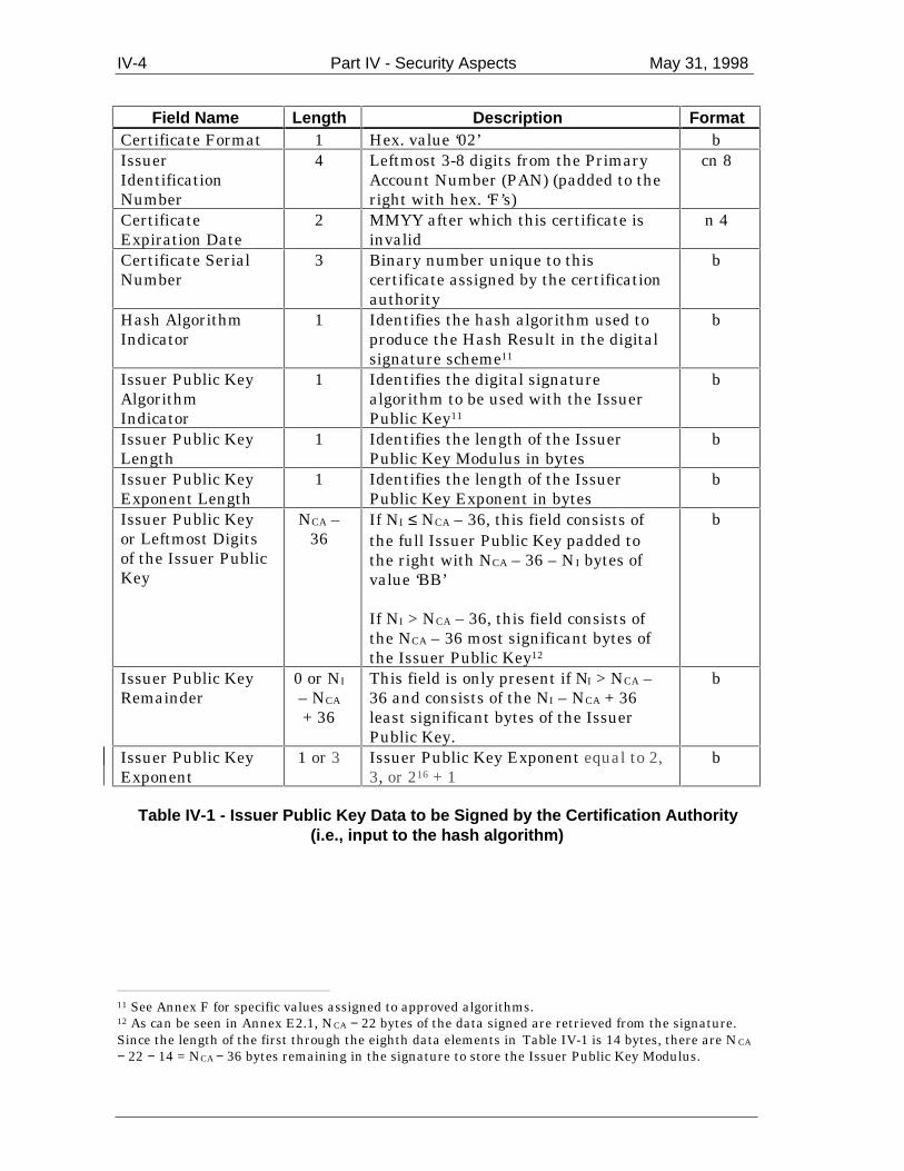
IV-4 Part IV - Security Aspects May 31, 1998
Field Name Length Description FormatCertificate Format 1 Hex. value ‘02’ bIssuerIdentificationNumber
4 Leftmost 3-8 digits from the PrimaryAccount Number (PAN) (padded to theright with hex. ‘F’s)
cn 8
CertificateExpiration Date
2 MMYY after which this certificate isinvalid
n 4
Certificate SerialNumber
3 Binary number unique to thiscertificate assigned by the certificationauthority
b
Hash AlgorithmIndicator
1 Identifies the hash algorithm used toproduce the Hash Result in the digitalsignature scheme11
b
Issuer Public KeyAlgorithmIndicator
1 Identifies the digital signaturealgorithm to be used with the IssuerPublic Key11
b
Issuer Public KeyLength
1 Identifies the length of the IssuerPublic Key Modulus in bytes
b
Issuer Public KeyExponent Length
1 Identifies the length of the IssuerPublic Key Exponent in bytes
b
Issuer Public Keyor Leftmost Digitsof the Issuer PublicKey
NCA –36
If NI ≤ NCA – 36, this field consists ofthe full Issuer Public Key padded tothe right with NCA – 36 – NI bytes ofvalue ‘BB’
If NI > NCA – 36, this field consists ofthe NCA – 36 most significant bytes ofthe Issuer Public Key12
b
Issuer Public KeyRemainder
0 or NI
– NCA
+ 36
This field is only present if NI > NCA –36 and consists of the NI – NCA + 36least significant bytes of the IssuerPublic Key.
b
Issuer Public KeyExponent
1 or 3 Issuer Public Key Exponent equal to 2,3, or 216 + 1
b
Table IV-1 - Issuer Public Key Data to be Signed by the Certification Authority(i.e., input to the hash algorithm)
11 See Annex F for specific values assigned to approved algorithms.12 As can be seen in Annex E2.1, NCA − 22 bytes of the data signed are retrieved from the signature.Since the length of the first through the eighth data elements in Table IV-1 is 14 bytes, there are NCA
− 22 − 14 = NCA − 36 bytes remaining in the signature to store the Issuer Public Key Modulus.

May 31, 1998 Part IV - Security Aspects IV-5
Field Name Length Description FormatSigned DataFormat
1 Hex. value ‘03’ b
Hash AlgorithmIndicator
1 Identifies the hash algorithm used toproduce the Hash Result in the digitalsignature scheme11
b
DataAuthenticationCode
2 Issuer-assigned code b
Pad Pattern NI − 26 Pad pattern consisting of NI − 26bytes of value ‘BB’13
b
Static Data to beAuthenticated
var. Static data to be authenticated asspecified in the ICC ApplicationSpecification for Payment Systems
-
Table IV-2 - Static Application Data to be Signed by the Issuer(i.e., input to the hash algorithm)
Tag Length Value Format- 5 Registered Application Provider Identifier (RID) b
‘8F’ 1 Certification Authority Public Key Index b‘90’ NCA Issuer Public Key Certificate b‘92’ NI – NCA
+ 36Issuer Public Key Remainder, if present b
‘9F32’ 1 or 3 Issuer Public Key Exponent b‘93’ NI Signed Static Application Data b
- var. Static data to be authenticated as specified in theICC Application Specification for PaymentSystems
-
Table IV-3 - Data Objects Required for Static Data Authentication
1.2 Retrieval of the Certification Authority Public Key
The terminal reads the Certification Authority Public Key Index. Using this indexand the RID, the terminal shall identify and retrieve the terminal-storedCertification Authority Public Key Modulus and Exponent and the associated key-related information, and the corresponding algorithm to be used. If the terminaldoes not have the key stored associated with this index and RID, static dataauthentication has failed.
13 As can be seen in Annex E2.1, NI − 22 bytes of the data signed are retrieved from the signature.Since the first through the third data elements in Table IV-2 total 4 bytes, there are NI − 22 − 4 = NI
− 26 bytes left for the data to be stored in the signature.
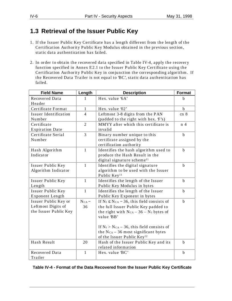
IV-6 Part IV - Security Aspects May 31, 1998
1.3 Retrieval of the Issuer Public Key 1. If the Issuer Public Key Certificate has a length different from the length of the
Certification Authority Public Key Modulus obtained in the previous section,static data authentication has failed.
2. In order to obtain the recovered data specified in Table IV-4, apply the recovery
function specified in Annex E2.1 to the Issuer Public Key Certificate using theCertification Authority Public Key in conjunction the corresponding algorithm. Ifthe Recovered Data Trailer is not equal to ‘BC’, static data authentication hasfailed.
Field Name Length Description FormatRecovered DataHeader
1 Hex. value ‘6A’ b
Certificate Format 1 Hex. value ‘02’ bIssuer IdentificationNumber
4 Leftmost 3-8 digits from the PAN(padded to the right with hex. ‘F’s)
cn 8
CertificateExpiration Date
2 MMYY after which this certificate isinvalid
n 4
Certificate SerialNumber
3 Binary number unique to thiscertificate assigned by thecertification authority
b
Hash AlgorithmIndicator
1 Identifies the hash algorithm used toproduce the Hash Result in thedigital signature scheme11
b
Issuer Public KeyAlgorithm Indicator
1 Identifies the digital signaturealgorithm to be used with the IssuerPublic Key11
b
Issuer Public KeyLength
1 Identifies the length of the IssuerPublic Key Modulus in bytes
b
Issuer Public KeyExponent Length
1 Identifies the length of the IssuerPublic Key Exponent in bytes
b
Issuer Public Key orLeftmost Digits ofthe Issuer Public Key
NCA −36
If NI ≤ NCA − 36, this field consists ofthe full Issuer Public Key padded tothe right with NCA – 36 – NI bytes ofvalue ‘BB’
If NI > NCA – 36, this field consists ofthe NCA – 36 most significant bytesof the Issuer Public Key12
b
Hash Result 20 Hash of the Issuer Public Key and itsrelated information
b
Recovered DataTrailer
1 Hex. value ‘BC’ b
Table IV-4 - Format of the Data Recovered from the Issuer Public Key Certificate

May 31, 1998 Part IV - Security Aspects IV-7
3. Check the Recovered Data Header. If it is not ‘6A’, static data authentication hasfailed.
4. Check the Certificate Format. If it is not ‘02’, static data authentication has
failed. 5. Concatenate from left to right the second to the tenth data elements in Table IV-4
(that is, Certificate Format through Issuer Public Key or Leftmost Digits of theIssuer Public Key), followed by the Issuer Public Key Remainder (if present) andfinally the Issuer Public Key Exponent.
6. Apply the indicated hash algorithm (derived from the Hash Algorithm Indicator)
to the result of the concatenation of the previous step to produce the hash result. 7. Compare the calculated hash result from the previous step with the recovered
Hash Result. If they are not the same, static data authentication has failed. 8. Verify that the Issuer Identification Number matches the leftmost 3-8 PAN digits
(allowing for the possible padding of the Issuer Identification Number withhexadecimal ‘F’s). If not, static data authentication has failed.
9. Verify that the last day of the month specified in the Certificate Expiration Date
is equal to or later than today's date. If the Certificate Expiration Date is earlierthan today's date, the certificate has expired, in which case static dataauthentication has failed.
10. Verify that the concatenation of RID, Certification Authority Public Key Index,
and Certificate Serial Number is valid. If not, static data authentication hasfailed14.
11. If the Issuer Public Key Algorithm Indicator is not recognised, static data
authentication has failed. 12. If all the checks above are correct, concatenate the Leftmost Digits of the Issuer
Public Key and the Issuer Public Key Remainder (if present) to obtain the IssuerPublic Key Modulus, and continue with the next steps for the verification of theSigned Static Application Data.
1.4 Verification of the Signed Static Application Data
1. If the Signed Static Application Data has a length different from the length of theIssuer Public Key Modulus, static data authentication has failed.
2. In order to obtain the Recovered Data specified in Table IV-5, apply the recovery
function specified in Annex E2.1 on the Signed Static Application Data using the
14 This step is optional and is to allow the revocation of the Issuer Public Key Certificate against a listthat may be kept by the terminal.

IV-8 Part IV - Security Aspects May 31, 1998
Issuer Public Key in conjunction the corresponding algorithm. If the RecoveredData Trailer is not equal to ‘BC’, static data authentication has failed.
Field Name Length Description FormatRecovered DataHeader
1 Hex. value ‘6A’ b
Signed DataFormat
1 Hex. value ‘03’ b
Hash AlgorithmIndicator
1 Identifies the hash algorithm used toproduce the Hash Result in the digitalsignature scheme11
b
DataAuthenticationCode
2 Issuer-assigned code b
Pad Pattern NI – 26 Pad pattern consisting of NI − 26 bytesof value ‘BB’13
b
Hash Result 20 Hash of the Static Application Data tobe authenticated
b
Recovered DataTrailer
1 Hex. value ‘BC’ b
Table IV-5 - Format of the Data Recovered from the Signed Static Application Data
3. Check the Recovered Data Header. If it is not ‘6A’, static data authentication hasfailed.
4. Check the Signed Data Format. If it is not ‘03’, static data authentication has
failed. 5. Concatenate from left to right the second to the fifth data elements in Table IV-5
(that is, Signed Data Format through Pad Pattern), followed by the static data tobe authenticated as specified in the ICC Application Specification for PaymentSystems.
6. Apply the indicated hash algorithm (derived from the Hash Algorithm Indicator)
to the result of the concatenation of the previous step to produce the hash result. 7. Compare the calculated hash result from the previous step with the recovered
Hash Result. If they are not the same, static data authentication has failed.
If all of the above steps were executed successfully, static data authentication wassuccessful.
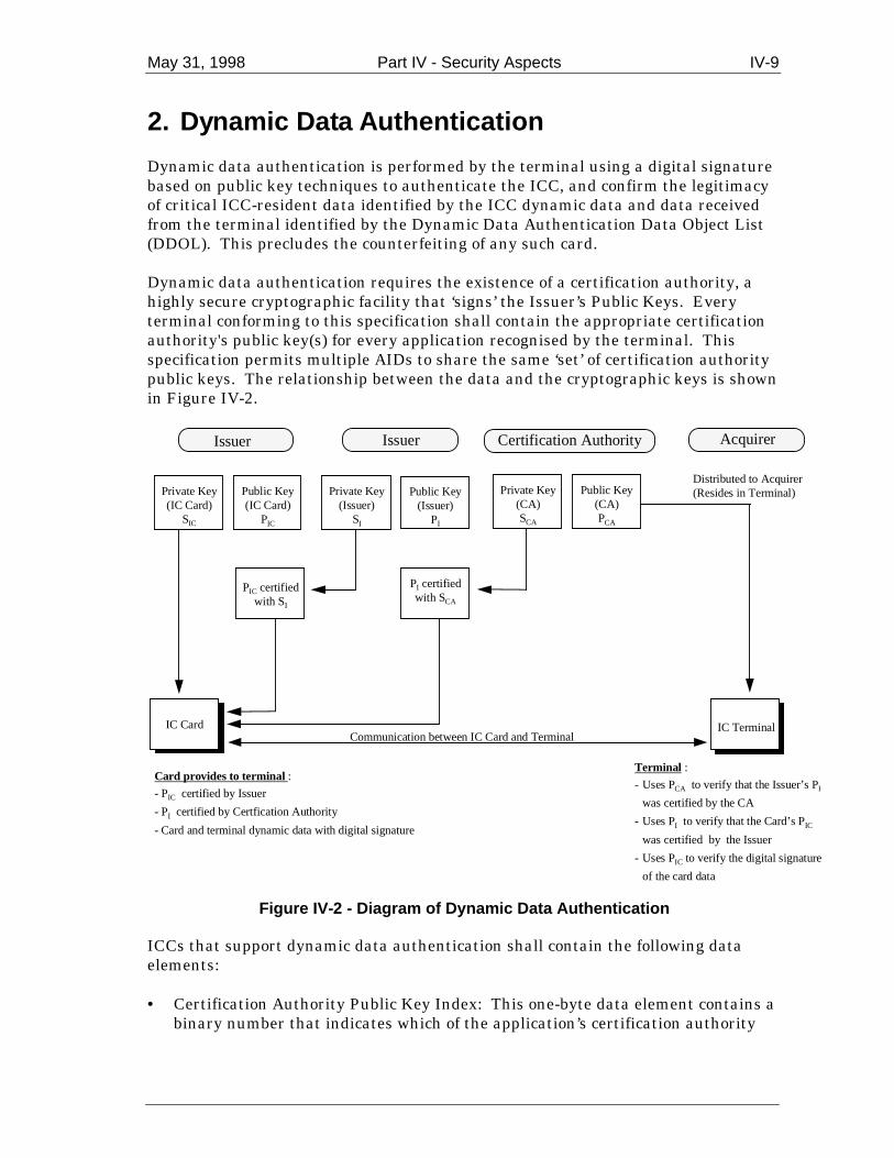
May 31, 1998 Part IV - Security Aspects IV-9
2. Dynamic Data Authentication
Dynamic data authentication is performed by the terminal using a digital signaturebased on public key techniques to authenticate the ICC, and confirm the legitimacyof critical ICC-resident data identified by the ICC dynamic data and data receivedfrom the terminal identified by the Dynamic Data Authentication Data Object List(DDOL). This precludes the counterfeiting of any such card.
Dynamic data authentication requires the existence of a certification authority, ahighly secure cryptographic facility that ‘signs’ the Issuer’s Public Keys. Everyterminal conforming to this specification shall contain the appropriate certificationauthority's public key(s) for every application recognised by the terminal. Thisspecification permits multiple AIDs to share the same ‘set’ of certification authoritypublic keys. The relationship between the data and the cryptographic keys is shownin Figure IV-2.
Issuer Issuer Acquirer
Private Key(IC Card)
SIC
Public Key(IC Card)
PIC
Private Key(Issuer)
SI
Public Key(Issuer)
PI
Private Key(CA)SCA
Public Key(CA)PCA
PIC certifiedwith SI
PI certifiedwith SCA
IC Card IC TerminalCommunication between IC Card and Terminal
Card provides to terminal :
- PIC certified by Issuer
- PI certified by Certfication Authority
- Card and terminal dynamic data with digital signature
Terminal :
- Uses PCA to verify that the Issuer’s PI
was certified by the CA
- Uses PI to verify that the Card’s PICwas certified by the Issuer
- Uses PIC to verify the digital signature
of the card data
Distributed to Acquirer(Resides in Terminal)
Certification Authority
Figure IV-2 - Diagram of Dynamic Data Authentication
ICCs that support dynamic data authentication shall contain the following dataelements:
• Certification Authority Public Key Index: This one-byte data element contains abinary number that indicates which of the application’s certification authority

IV-10 Part IV - Security Aspects May 31, 1998
public keys and its associated algorithm that reside in the terminal is to be usedwith this ICC.
• Issuer Public Key Certificate: This variable-length data element is provided by
the appropriate certification authority to the card issuer. When the terminalverifies this data element, it authenticates the Issuer Public Key plus additionaldata as described in section IV-2.3.
• ICC Public Key Certificate: This variable-length data element is provided by the
issuer to the ICC. When the terminal verifies this data element, it authenticatesthe ICC Public Key plus additional data as described in section IV-2.4.
• Issuer Public Key Remainder: A variable-length data element. See section IV-
2.1 for further explanation. • Issuer Public Key Exponent: A variable-length data element provided by the
issuer. See section IV-2.1 for further explanation. • ICC Public Key Remainder: A variable-length data element. See section IV-2.1
for further explanation. • ICC Public Key Exponent: A variable-length data element provided by the
issuer. See section IV-2.1 for further explanation. • ICC Private Key: An ICC internal variable-length data element used to
generate the Signed Dynamic Application Data as described in section IV-2.5.
ICCs that support dynamic data authentication shall generate the following dataelement:
• Signed Dynamic Application Data: A variable-length data element generated bythe ICC using the private key that corresponds to the public key authenticatedin the ICC Public Key Certificate. It is a digital signature covering critical ICC-resident and terminal data elements, as described in section IV-2.5.
To support dynamic data authentication, each terminal shall be able to storemultiple certification authority public keys and shall associate with each such keythe key-related information to be used with the key (so that terminals can in thefuture support multiple algorithms and allow an evolutionary transition from one toanother). The terminal shall be able to locate any such key (and key-relatedinformation) given the RID and Certification Authority Public Key Index asprovided by the ICC.
Dynamic data authentication shall use a reversible algorithm as specified in AnnexE2.1 and Annex F2. Section IV-2.1 contains an overview of the keys and certificatesinvolved in the dynamic data authentication process, and sections IV-2.3 to IV-2.6specify the five main steps in the process, namely

May 31, 1998 Part IV - Security Aspects IV-11
• Retrieval of the Certification Authority Public Key by the terminal. • Retrieval of the Issuer Public Key by the terminal. • Retrieval of the IC Public Key by the terminal. • Dynamic signature generation by the ICC. • Dynamic signature verification by the terminal.
2.1 Keys and Certificates
To support dynamic data authentication, an ICC shall own its own unique publickey pair consisting of a private signature key and the corresponding publicverification key. The ICC Public Key shall be stored on the ICC in a public keycertificate.
More precisely, a three-layer public key certification scheme is used. Each ICCPublic Key is certified by its issuer, and the certification authority certifies theIssuer Public Key. This implies that, for the verification of an ICC signature, theterminal first needs to verify two certificates in order to retrieve and authenticatethe ICC Public Key, which is then employed to verify the ICC’s dynamic signature.
The bit length of all moduli shall be a multiple of 8, the leftmost bit of its leftmostbyte being 1. All lengths are given in bytes.
The signature scheme specified in Annex E2.1 is applied on the data in Table IV-6and on the data in Table IV-7 using the Certification Authority Private Key SCA andthe Issuer Private Key SI in order to obtain the Issuer Public Key Certificate andICC Public Key Certificate, respectively.
The public key pair of the certification authority has a Certification Authority PublicKey Modulus of NCA bytes, where NCA ≤ 248. The Certification Authority Public KeyExponent shall be equal to 2, 3, or 216 + 1.
The public key pair of the issuer has a Public Key Modulus of NI bytes, where NI <248 and NI < NCA. If NI > (NCA – 36), the Issuer Public Key Modulus is divided intotwo parts, one part consisting of the NCA – 36 most significant bytes of the modulus(the Leftmost Digits of the Issuer Public Key) and a second part consisting of theremaining NI − (NCA – 36) least significant bytes of the modulus (the Issuer PublicKey Remainder). The Issuer Public Key Exponent shall be equal to 2, 3, or 216 + 1.
The public key pair of the ICC has an ICC Public Key Modulus of NIC bytes, whereNIC ≤ 128 and NIC < NI. If NIC > (NI – 42), the ICC Public Key Modulus is dividedinto two parts, one part consisting of the NI – 42 most significant bytes of themodulus (the Leftmost Digits of the ICC Public Key) and a second part consisting ofthe remaining NIC – (NI – 42) least significant bytes of the modulus (the ICC PublicKey Remainder). The ICC Public Key Exponent shall be equal to 2, 3, or 216 + 1.

IV-12 Part IV - Security Aspects May 31, 1998
To execute dynamic data authentication, the terminal shall first retrieve andauthenticate the ICC Public Key (this process is called ICC Public Keyauthentication). All the information necessary for ICC Public Key authentication isspecified in Table IV-8 and stored in the ICC. With the exception of the RID, whichcan be obtained from the AID, this information may be retrieved with the READRECORD command. If any of this data is missing, dynamic data authentication hasfailed.
Field Name Length Description FormatCertificate Format 1 Hex. value ‘02’ bIssuer IdentificationNumber
4 Leftmost 3-8 digits from the PAN(padded to the right with hex. ‘F’s)
cn 8
CertificateExpiration Date
2 MMYY after which this certificate isinvalid
n 4
Certificate SerialNumber
3 Binary number unique to thiscertificate assigned by thecertification authority
b
Hash AlgorithmIndicator
1 Identifies the hash algorithm used toproduce the Hash Result in thedigital signature scheme11
b
Issuer Public KeyAlgorithm Indicator
1 Identifies the digital signaturealgorithm to be used with the IssuerPublic Key 11
b
Issuer Public KeyLength
1 Identifies the length of the IssuerPublic Key Modulus in bytes
b
Issuer Public KeyExponent Length
1 Identifies the length of the IssuerPublic Key Exponent in bytes
b
Issuer Public Key orLeftmost Digits ofthe Issuer PublicKey
NCA –36
If NI ≤ NCA – 36, this field consists ofthe full Issuer Public Key padded tothe right with NCA – 36 – NI bytes ofvalue ‘BB’
If NI > NCA – 36, this field consists ofthe NCA – 36 most significant bytesof the Issuer Public Key 12
b
Issuer Public KeyRemainder
0 or NI
– NCA
+ 36
This field is only present if NI > NCA
– 36 and consists of the NI – NCA +36 least significant bytes of theIssuer Public Key
b
Issuer Public KeyExponent
1 or 3 Issuer Public Key Exponent equal to2, 3 or 216 + 1
b
Table IV-6 - Issuer Public Key Data to be Signed by the Certification Authority(i.e., input to the hash algorithm)

May 31, 1998 Part IV - Security Aspects IV-13
Field Name Length Description FormatCertificate Format 1 Hex. value ‘04’ bApplication PAN 10 PAN (padded to the right with hex.
‘F’s)cn 20
CertificateExpiration Date
2 MMYY after which this certificate isinvalid
n 4
Certificate SerialNumber
3 Binary number unique to thiscertificate assigned by the issuer
b
Hash AlgorithmIndicator
1 Identifies the hash algorithm used toproduce the Hash Result in thedigital signature scheme11
b
ICC Public KeyAlgorithm Indicator
1 Identifies the digital signaturealgorithm to be used with the ICCPublic Key11
b
ICC Public KeyLength
1 Identifies the length of the ICCPublic Key Modulus in bytes
b
ICC Public KeyExponent Length
1 Identifies the length of the ICCPublic Key Exponent in bytes
b
ICC Public Key orLeftmost Digits ofthe ICC Public Key
NI – 42 If NIC ≤ NI –42, this field consists ofthe full ICC Public Key padded tothe right with NI – 42 – NIC bytes ofvalue ‘BB’
If NIC > NI – 42, this field consists ofthe NI – 42 most significant bytes ofthe ICC Public Key 15
b
ICC Public KeyRemainder
0 orNIC –
NI + 42
This field is only present if NIC > NI –42 and consists of the NI – NCA + 42least significant bytes of the ICCPublic Key
b
ICC Public KeyExponent
1 or 3 ICC Public Key Exponent equal to 2,3 or 216 + 1
b
Static Data to beAuthenticated
var. Static data to be authenticated asspecified in the ICC ApplicationSpecification for Payment Systems
b
Table IV-7 - ICC Public Key Data to be Signed by the Issuer(i.e., input to the hash algorithm)
15 As can be seen in Annex E2.1, NI − 22 bytes of the data signed are retrieved from the signature.Since the first through the eighth data elements in Table IV-7 total 20 bytes, there are NI − 22 − 20 =NI − 42 bytes left for the data to be stored in the signature.

IV-14 Part IV - Security Aspects May 31, 1998
Tag Length Value Format- 5 Registered Application Provider Identifier (RID) b
‘8F’ 1 Certification Authority Public Key Index b‘90’ NCA Issuer Public Key Certificate b‘92’ NI – NCA +
36Issuer Public Key Remainder, if present b
‘9F32’ 1 or 3 Issuer Public Key Exponent b‘9F46’ NI ICC Public Key Certificate b‘9F48’ NIC – NI +
42ICC Public Key Remainder, if present b
‘9F47’ 1 or 3 ICC Public Key Exponent b- var. Static data to be authenticated as specified in
the ICC Application Specification for PaymentSystems
-
Table IV-8 - Data Objects Required for Public Key Authentication for DynamicAuthentication
2.2 Retrieval of the Certification Authority Public Key
The terminal reads the Certification Authority Public Key Index. Using this indexand the RID, the terminal can identify and retrieve the terminal-stored CertificationAuthority Public Key Modulus and Exponent and the associated key-relatedinformation, and the corresponding algorithm to be used. If the terminal does nothave the key stored associated with this index and RID, dynamic dataauthentication has failed.
2.3 Retrieval of the Issuer Public Key
1. If the Issuer Public Key Certificate has a length different from the length of theCertification Authority Public Key Modulus obtained in the previous section,dynamic data authentication has failed.
2. In order to obtain the recovered data specified in Table IV-9, apply the recovery
function specified in Annex E2.1 on the Issuer Public Key Certificate using theCertification Authority Public Key in conjunction the corresponding algorithm. Ifthe Recovered Data Trailer is not equal to ‘BC’, dynamic data authentication hasfailed.

May 31, 1998 Part IV - Security Aspects IV-15
Field Name Length Description FormatRecovered DataHeader
1 Hex. value ‘6A’ b
Certificate Format 1 Hex. value ‘02’ bIssuer IdentificationNumber
4 Leftmost 3-8 digits from the PAN(padded to the right with hex. ‘F’s)
cn 8
CertificateExpiration Date
2 MMYY after which this certificate isinvalid
n 4
Certificate SerialNumber
3 Binary number unique to thiscertificate assigned by thecertification authority
b
Hash AlgorithmIndicator
1 Identifies the hash algorithm used toproduce the Hash Result in thedigital signature scheme11
b
Issuer Public KeyAlgorithm Indicator
1 Identifies the digital signaturealgorithm to be used with the IssuerPublic Key11
b
Issuer Public KeyLength
1 Identifies the length of the IssuerPublic Key Modulus in bytes
b
Issuer Public KeyExponent Length
1 Identifies the length of the IssuerPublic Key Exponent in bytes
b
Issuer Public Key orLeftmost Digits ofthe Issuer PublicKey
NCA –36
If NI ≤ NCA – 36, this field consists ofthe full Issuer Public Key padded tothe right with NCA – 36 – NI bytes ofvalue ‘BB’
If NI > NCA – 36, this field consists ofthe NCA – 36 most significant bytesof the Issuer Public Key12
b
Hash Result 20 Hash of the Issuer Public Key and itsrelated information
b
Recovered DataTrailer
1 Hex. value ‘BC’ b
Table IV-9 - Format of the Data Recovered from the Issuer Public Key Certificate
3. Check the Recovered Data Header. If it is not ‘6A’, dynamic data authenticationhas failed.
4. Check the Certificate Format. If it is not ‘02’, dynamic data authentication has
failed. 5. Concatenate from left to right the second to the tenth data elements in Table IV-9
(that is, Certificate Format through Issuer Public Key or Leftmost Digits of theIssuer Public Key), followed by the Issuer Public Key Remainder (if present) andfinally the Issuer Public Key Exponent.
IV-16 Part IV - Security Aspects May 31, 1998
6. Apply the indicated hash algorithm (derived from the Hash Algorithm Indicator)to the result of the concatenation of the previous step to produce the hash result.
7. Compare the calculated hash result from the previous step with the recovered
Hash Result. If they are not the same, dynamic data authentication has failed. 8. Verify that the Issuer Identification Number matches the leftmost 3-8 PAN digits
(allowing for the possible padding of the Issuer Identification Number withhexadecimal ‘F’s). If not, dynamic data authentication has failed.
9. Verify that the last day of the month specified in the Certificate Expiration Date
is equal to or later than today's date. If the Certificate Expiration Date is earlierthan today's date, the certificate has expired, in which case dynamic dataauthentication has failed.
10. Verify that the concatenation of RID, Certification Public Key Index, and
Certificate Serial Number is valid. If not, dynamic data authentication hasfailed14.
11. If the Issuer Public Key Algorithm Indicator is not recognised, dynamic data
authentication has failed. 12. If all the checks above are correct, concatenate the Leftmost Digits of the Issuer
Public Key and the Issuer Public Key Remainder (if present) to obtain the IssuerPublic Key Modulus, and continue with the next steps for the retrieval of the ICCPublic Key.
2.4 Retrieval of the ICC Public Key
1. If the ICC Public Key Certificate has a length different from the length of theIssuer Public Key Modulus obtained in the previous section, dynamic dataauthentication has failed.
2. In order to obtain the recovered data specified in Table IV-10, apply the recovery
function specified in Annex E2.1 on the ICC Public Key Certificate using theIssuer Public Key in conjunction the corresponding algorithm. If the RecoveredData Trailer is not equal to ‘BC’, dynamic data authentication has failed.
May 31, 1998 Part IV - Security Aspects IV-17
Field Name Length Description FormatRecovered DataHeader
1 Hex. value ‘6A’ b
Certificate Format 1 Hex. value ‘04’ bApplication PAN 10 PAN (padded to the right with hex.
‘F’scn 20
CertificateExpiration Date
2 MMYY after which this certificate isinvalid
n 4
Certificate SerialNumber
3 Binary number unique to thiscertificate assigned by the issuer
b
Hash AlgorithmIndicator
1 Identifies the hash algorithm used toproduce the Hash Result in thedigital signature scheme11
b
ICC Public KeyAlgorithm Indicator
1 Identifies the digital signaturealgorithm to be used with the ICCPublic Key11
b
ICC Public KeyLength
1 Identifies the length of the ICCPublic Key Modulus in bytes
b
ICC Public KeyExponent Length
1 Identifies the length of the ICCPublic Key Exponent in bytes
b
ICC Public Key orLeftmost Digits ofthe ICC Public Key
NI – 42 If NIC ≤ NI – 42, this field consists ofthe full ICC Public Key padded tothe right with NI – 42 – NIC bytes ofvalue ‘BB’15
If NIC > NI – 42, this field consists ofthe NI − 42 most significant bytes ofthe ICC Public Key
b
Hash Result 20 Hash of the ICC Public Key and itsrelated information
b
Recovered DataTrailer
1 Hex. value ‘BC’ b
Table IV-10 - Format of the Data Recovered from the ICC Public Key Certificate
3. Check the Recovered Data Header. If it is not ‘6A’, dynamic data authenticationhas failed.
4. Check the Certificate Format. If it is not ‘04’, dynamic data authentication has
failed. 5. Concatenate from left to right the second to the tenth data elements in Table IV-
10 (that is, Certificate Format through ICC Public Key or Leftmost Digits of theICC Public Key), followed by the ICC Public Key Remainder (if present), the ICCPublic Key Exponent and finally the static data to be authenticated specified inthe ICC Application Specification for Payment Systems.
IV-18 Part IV - Security Aspects May 31, 1998
6. Apply the indicated hash algorithm (derived from the Hash Algorithm Indicator)to the result of the concatenation of the previous step to produce the hash result.
7. Compare the calculated hash result from the previous step with the recovered
Hash Result. If they are not the same, dynamic data authentication has failed. 8. Check if the recovered PAN is equal to the Application PAN, read from the ICC. If
not, dynamic data authentication has failed. 9. Verify that the last day of the month specified in the Certificate Expiration Date
is equal to or later than today’s date. If not, dynamic data authentication hasfailed.
10. If the ICC Public Key Algorithm Indicator is not recognised, dynamic data
authentication has failed. 11. If all the checks above are correct, concatenate the Leftmost Digits of the ICC
Public Key and the ICC Public Key Remainder (if present) to obtain the ICCPublic Key Modulus, and continue with the actual dynamic data authenticationdescribed in the two sections below.
2.5 Dynamic Signature Generation
1. After successfully retrieving the ICC Public Key as described above, the terminalissues an INTERNAL AUTHENTICATE command including the concatenation ofthe data elements specified by the DDOL according to the rules specified in PartII of this specification.
The ICC may contain the DDOL, but there shall be a default DDOL in the
terminal, specified by the payment system, for use in case the DDOL is notpresent in the ICC.
It is mandatory that the DDOL contains the Unpredictable Number generated by
the terminal (tag ‘9F37’, 4 bytes binary).
If any of the following cases occur, dynamic data authentication has failed.
• Both the ICC and the terminal do not contain a DDOL. • The DDOL in the ICC does not include the Unpredictable Number. • The ICC does not contain a DDOL and the default DDOL in the terminal
does not include the Unpredictable Number.
2. The ICC generates a digital signature as described in Annex E2.1 on the dataspecified in Table IV-11 using its ICC Private Key SIC in conjunction thecorresponding algorithm. The result is called the Signed Dynamic Application
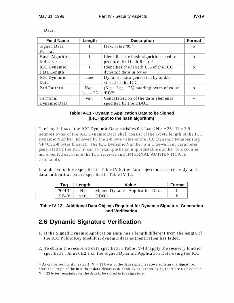
May 31, 1998 Part IV - Security Aspects IV-19
Data.
Field Name Length Description FormatSigned DataFormat
1 Hex. value ‘05’ b
Hash AlgorithmIndicator
1 Identifies the hash algorithm used toproduce the Hash Result1
b
ICC DynamicData Length
1 Identifies the length LDD of the ICCdynamic data in bytes
b
ICC DynamicData
LDD Dynamic data generated by and/orstored in the ICC
-
Pad Pattern NIC –LDD – 25
(NIC – LDD – 25) padding bytes of value‘BB’16
b
TerminalDynamic Data
var. Concatenation of the data elementsspecified by the DDOL
-
Table IV-11 - Dynamic Application Data to be Signed(i.e., input to the hash algorithm)
The length LDD of the ICC Dynamic Data satisfies 0 ≤ LDD ≤ NIC − 25. The 3-9leftmost bytes of the ICC Dynamic Data shall consist of the 1-byte length of the ICCDynamic Number, followed by the 2-8 byte value of the ICC Dynamic Number (tag‘9F4C’, 2-8 bytes binary). The ICC Dynamic Number is a time-variant parametergenerated by the ICC (it can for example be an unpredictable number or a counterincremented each time the ICC receives and INTERNAL AUTHENTICATEcommand).
In addition to those specified in Table IV-8, the data objects necessary for dynamicdata authentication are specified in Table IV-12.
Tag Length Value Format‘9F4B’ NIC Signed Dynamic Application Data b‘9F49’ var. DDOL b
Table IV-12 - Additional Data Objects Required for Dynamic Signature Generationand Verification
2.6 Dynamic Signature Verification
1. If the Signed Dynamic Application Data has a length different from the length ofthe ICC Public Key Modulus, dynamic data authentication has failed.
2. To obtain the recovered data specified in Table IV-13, apply the recovery function
specified in Annex E2.1 on the Signed Dynamic Application Data using the ICC 16 As can be seen in Annex E2.1, NI − 22 bytes of the data signed is recovered from the signature.Since the length of the first three data elements in Table IV-11 is three bytes, there are NI − 22 − 3 =NI − 25 bytes remaining for the data to be stored in the signature.

IV-20 Part IV - Security Aspects May 31, 1998
Public Key in conjunction the corresponding algorithm. If the Recovered DataTrailer is not equal to ‘BC’, dynamic data authentication has failed.
Field Name Length Description FormatRecovered DataHeader
1 Hex. value ‘6A’ b
Signed DataFormat
1 Hex. value ‘05’ b
Hash AlgorithmIndicator
1 Identifies the hash algorithm used toproduce the Hash Result in the digitalsignature scheme11
b
ICC DynamicData Length
1 Identifies the length of the ICCdynamic data in bytes
b
ICC DynamicData
LDD Dynamic data generated by and/orstored in the ICC
-
Pad Pattern NIC –LDD – 25
(NIC – LDD – 25) padding bytes of value‘BB’16
b
Hash Result 20 Hash of the Dynamic Application Dataand its related information
b
Recovered DataTrailer
1 Hex. value ‘BC’ b
Table IV-13 - Format of the Data Recovered from the Signed Dynamic ApplicationData
3. Check the Recovered Data Header. If it is not ‘6A’, dynamic data authenticationhas failed.
4. Check the Signed Data Format. If it is not ‘05’, dynamic data authentication has
failed. 5. Concatenate from left to right the second to the sixth data elements in Table IV-
13 (that is, Signed Data Format through Pad Pattern), followed by the dataelements specified by the DDOL.
6. Apply the indicated hash algorithm (derived from the Hash Algorithm Indicator)
to the result of the concatenation of the previous step to produce the hash result. 7. Compare the calculated hash result from the previous step with the recovered
Hash Result. If they are not the same, dynamic data authentication has failed.
If all the above steps were executed successfully, dynamic data authentication wassuccessful.
May 31, 1998 Part IV - Security Aspects IV-21
3. Secure Messaging
The objectives of secure messaging are to ensure data confidentiality, data integrityand authentication of the sender. Data integrity and issuer authentication areachieved using a MAC. Data confidentiality is achieved using encipherment of thedata field.
3.1 Secure Messaging Format
Secure messaging shall be according to one of the following two formats.
• Format 1: Secure messaging format according to ISO/IEC 7816-4, section 5.6,where the data field of the affected command uses BER-TLV encoding andencoding rules of ASN.1/ISO 8825 apply strictly. This is explicitly specified in thelowest significant nibble of the class byte of the command, which is set to ‘C’.This also implies that the command header is always integrated in MACcalculation.
• Format 2: Secure messaging format where the data field of the affected
command does not use BER-TLV encoding for secure messaging, but may use itfor other purposes. In this case, the data objects contained in the data field andcorresponding lengths of these data objects shall be known by the sender of acommand using secure messaging and known by the currently selectedapplication. In compliance with ISO/IEC 7816-4, secure messaging according toFormat 2 is explicitly specified in the lowest significant nibble of the class byte ofthe command, which is set to ‘4’.
3.2 Secure Messaging for Integrity and Authentication
3.2.1 Command Data Field
3.2.1.1 Format 1
The data field of the command is composed of the following TLV data objects asshown in Figure IV-3.
• The command data to be signed, if present. If the command data field is BER-TLV encoded, it shall either not belong to the
context-specific class (the tag shall not lie in the range ‘80’ to ‘BF’) or shall havean odd tag (note that this may be a constructed data object).
If the command data field is not BER-TLV encoded, it shall be encapsulated with
the template ‘81’. • The second data object is the MAC. Its tag is ‘8E’, and its length shall be in the
range of four to eight bytes.

IV-22 Part IV - Security Aspects May 31, 1998
Tag 1 Length 1 Value 1 Tag 2 Length 2 Value 2T L Value
(L bytes)‘8E’ ‘04’-‘08’ MAC (4-8 bytes)
Figure IV-3 - Format 1 Command Data Field for Secure Messaging for Integrity andAuthentication
3.2.1.2 Format 2
The data elements (including the MAC) contained in the data field and thecorresponding lengths shall be known by the sender of a command using securemessaging and known by the currently selected application. The MAC is not BER-TLV coded and shall always be the last data element in the data field and its lengthshall be in the range of 4 to 8 bytes (see Figure IV-4).
Value 1 Value 2Command data (if present) MAC (4-8 bytes)
Figure IV-4 - Format 2 Command Data Field for Secure Messaging for Integrity andAuthentication
3.2.2 MAC Session Key Derivation
The first step of the MAC generation for secure messaging for integrity consists ofderiving a unique MAC Session Key from the ICC’s unique MAC Master Key asdescribed in Annex E1.3.
3.2.3 MAC Computation
The MAC is computed by applying the mechanism described in Annex E1.2 with theMAC Session Key derived as described in section IV-3.2.2 to the message to beprotected.
If secure messaging is according to Format 1, the message to be protected shall beconstructed from the header of the command APDU (CLA INS P1 P2) and thecommand data (if present) according to the rules specified in ISO/IEC 7816-4,Section 5.6.
If secure messaging is according to Format 2, the message to be protected shall beconstructed according to the payment scheme proprietary specifications. It shallhowever always contain the header of the command APDU and the command data(if present).
In all cases, if the MAC used for secure messaging has been specified as having alength less than 8 bytes, the MAC is obtained by taking the leftmost (mostsignificant) bytes from the 8-byte result of the calculation described above.

May 31, 1998 Part IV - Security Aspects IV-23
3.3 Secure Messaging for Confidentiality
3.3.1 Command Data Field
3.3.1.1 Format 1
The format of an enciphered data object in a command data field is shown in FigureIV-5.
Tag Length ValueT L Cryptogram (enciphered data)
Figure IV-5 - Format 1 Enciphered Data Object in a Command Data Field
Depending on the plaintext data to be enciphered, ISO/IEC 7816-4 specifies the tagto be allocated to the resulting cryptogram. An odd tag shall be used if the object isto be integrated in the computation of a MAC; an even tag shall be used otherwise.
3.3.1.2 Format 2
Data encipherment is applied to the full plaintext command data field with theexception of a MAC (see Figure IV-6).
Value1 Value2Cryptogram (enciphered data) MAC (if present)
Figure IV-6 - Format 2 Command Data Field for Secure Messaging forConfidentiality
3.3.2 Encipherment Session Key Derivation
The first step of the encipherment/decipherment for secure messaging forconfidentiality consists of deriving a unique Encipherment Session Key from theICC’s unique Encipherment Master Key as described in Annex E1.3.
3.3.3 Encipherment/Decipherment
Encipherment/decipherment of the plain/enciphered command data field takes placeaccording to the mechanism described in Annex E1.1 with the Encipherment SessionKey derived as described in the section IV-3.3.2.

IV-24 Part IV - Security Aspects May 31, 1998
4. Personal Identification Number Encipherment
If supported, Personal Identification Number (PIN) encipherment for offline PINverification is performed by the terminal using an asymmetric based enciphermentmechanism in order to ensure the secure transfer of a PIN from a secure tamper-evident PIN pad integrated in the terminal to the ICC.
More precisely, the ICC shall own a public key pair associated with PINencipherment. The public key is then used by the PIN pad to encipher the PIN, andthe private key is used by the ICC to verify the enciphered PIN.
The PIN block used in the data field to be enciphered shall be 8 bytes as shown inSection 4.2.
4.1 Keys and Certificates
If offline PIN encipherment is supported, the ICC shall own a unique public key pairconsisting of a public encipherment key and the corresponding private deciphermentkey. This specification allows the following two possibilities.
1. The ICC owns a specific ICC PIN Encipherment Private and Public Key. TheICC PIN Encipherment Public Key shall be stored on the ICC in a public keycertificate in exactly the same way as for the ICC Public Key for dynamic dataauthentication as specified in Section IV-2.
The ICC PIN encipherment public key pair has an ICC PIN Encipherment
Public Key Modulus of NPE bytes, where NPE ≤ 128 and NPE < NI, NI being thelength of the Issuer Public Key Modulus (See section IV-2.1). If NPE > (NI − 42),the ICC PIN Encipherment Public Key Modulus is divided into two parts, onepart consisting of the NI − 42 most significant bytes of the modulus (theLeftmost Digits of the ICC PIN Encipherment Public Key) and a second partconsisting of the remaining NPE − (NI − 42) least significant bytes of the modulus(the ICC PIN Encipherment Public Key Remainder).
The ICC PIN Encipherment Public Key Exponent shall be equal to 3 or 216+1.
The ICC PIN Encipherment Public Key Certificate is obtained by applying thedigital signature scheme specified in Annex E2.1 on the data in Table IV-14using the Issuer Private Key (see Section IV-2.1).
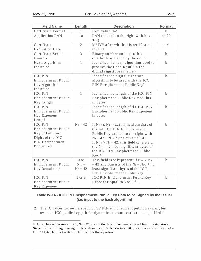
May 31, 1998 Part IV - Security Aspects IV-25
Field Name Length Description FormatCertificate Format 1 Hex. value ‘04’ bApplication PAN 10 PAN (padded to the right with hex.
‘F’s)cn 20
CertificateExpiration Date
2 MMYY after which this certificate isinvalid
n 4
Certificate SerialNumber
3 Binary number unique to thiscertificate assigned by the issuer
b
Hash AlgorithmIndicator
1 Identifies the hash algorithm used toproduce the Hash Result in thedigital signature scheme11
b
ICC PINEncipherment PublicKey AlgorithmIndicator
1 Identifies the digital signaturealgorithm to be used with the ICCPIN Encipherment Public Key11
b
ICC PINEncipherment PublicKey Length
1 Identifies the length of the ICC PINEncipherment Public Key Modulusin bytes
b
ICC PINEncipherment PublicKey ExponentLength
1 Identifies the length of the ICC PINEncipherment Public Key Exponentin bytes
b
ICC PINEncipherment PublicKey or LeftmostDigits of the ICCPIN EnciphermentPublic Key
NI – 42 If NPE ≤ NI –42, this field consists ofthe full ICC PIN EnciphermentPublic Key padded to the right withNI – 42 – NPE bytes of value ‘BB’If NPE > NI – 42, this field consists ofthe NI – 42 most significant bytes ofthe ICC PIN Encipherment PublicKey 17
b
ICC PINEncipherment PublicKey Remainder
0 orNIC –
NI + 42
This field is only present if NPE > NI
– 42 and consists of the NI – NPE + 42least significant bytes of the ICCPIN Encipherment Public Key
b
ICC PINEncipherment PublicKey Exponent
1 or 3 ICC PIN Encipherment Public KeyExponent equal to 3 or 216+1
b
Table IV-14 - ICC PIN Encipherment Public Key Data to be Signed by the Issuer(i.e. input to the hash algorithm)
2. The ICC does not own a specific ICC PIN encipherment public key pair, butowns an ICC public key pair for dynamic data authentication a specified in
17 As can be seen in Annex E2.1, NI − 22 bytes of the data signed are retrieved from the signature.Since the first through the eighth data elements in Table IV-7 total 20 bytes, there are NI − 22 − 20 =NI − 42 bytes left for the data to be stored in the signature.

IV-26 Part IV - Security Aspects May 31, 1998
Section 2.1 of this specification. This key pair can then be used for PINencipherment, if and only if the ICC Public Key Exponent is equal to 3 or 216+1.The ICC Public Key is stored on the ICC in a public key certificate as specifiedin Section 2.
The first step of PIN encipherment shall be the retrieval of the public key to be usedby the terminal for the encipherment of the PIN. This process takes place as follows.
1. If the terminal has obtained all the data objects specified in Table IV-15 from theICC, then the terminal retrieves the ICC PIN Encipherment Public Key inexactly the same way as it retrieves the ICC Public Key for dynamic dataauthentication (see Section IV-2).
2. If the terminal has not obtained all the data objects specified in Table IV-15, but
has obtained all the data objects specified in Table IV-8, and the ICC Public KeyExponent is equal to 3 or 216+1, then the terminal retrieves the ICC Public Keyas described in Section IV-2.
3. If the conditions under points 1 and 2 above are not satisfied, then PIN
encipherment has failed.
Tag Length Value Format- 5 Registered Application Provider Identifier (RID) b
‘8F’ 1 Certification Authority Public Key Index b‘90’ NCA Issuer Public Key Certificate b‘92’ NI – NCA +
36Issuer Public Key Remainder, if present b
‘9F32’ 1 or 3 Issuer Public Key Exponent b‘9F2D’ NI ICC PIN Encipherment Public Key Certificate b‘9F2E’ NPE – NI +
42ICC PIN Encipherment Public Key Remainder, ifpresent
b
‘9F2F’ 1 or 3 ICC PIN Encipherment Public Key Exponent b
Table IV-15 - Data Objects Required for the Retrieval of the ICC PIN EnciphermentPublic Key
4.2 PIN Encipherment and Verification
The exchange and verification of an enciphered PIN between terminal and ICCtakes place in the following steps.
1. The PIN is entered in plaintext format on the PIN pad and a PIN block isconstructed as defined in Part II of this specification.
2. The terminal issues a GET CHALLENGE command to the ICC to obtain an 8-
byte unpredictable number from the ICC.

May 31, 1998 Part IV - Security Aspects IV-27
3. The terminal generates a Random Pad Pattern consisting of N − 17 bytes,where N is the length in bytes of the public key to be used for PIN enciphermentretrieved as specified in Section IV-4.1 (hence N = NPE or N = NIC).
4. Using the PIN Encipherment Public Key or the ICC Public Key retrieved as
specified in Section IV-4.1, the terminal applies the RSA Recovery Functionspecified Annex F2.1.1.3 to the data specified in Table IV-16 in order to obtainthe Enciphered PIN Data.
Field Name Length Description FormatData Header 1 Hex. value ‘7F’ bPIN Block 8 PIN in PIN Block bICC Unpredictable Number 8 Unpredictable number obtained from
the ICC with the GET CHALLENGEcommand
b
Random Pad Pattern NIC – 17 Random Pad Pattern generated by theterminal
b
Table IV-16 - Data to be Enciphered for PIN Encipherment
5. The terminal issues a VERIFY command including the Enciphered PIN Dataobtained in the previous step.
6. With the ICC Private Key, the ICC applies the RSA Signing Function specified
in Annex F2.1.1.2 to the Enciphered PIN Data in order to recover the plain textdata specified in Table IV-15.
7. The ICC verifies whether the Data Header recovered is equal to ‘7F’. If this is
not the case, PIN verification has failed. 8. The ICC verifies whether the ICC Unpredictable Number recovered is equal to
the ICC Unpredictable Number generated by the ICC with the GETCHALLENGE command. If this is not the case, PIN verification has failed.
9. The ICC verifies whether the PIN included in the recovered PIN Block
corresponds with the PIN stored in the ICC. If this is not the case, PINverification has failed.
If all the above steps were executed successfully, enciphered PIN verification wassuccessful.
In order for this mechanism to be secure, the steps 1 through 4 must be executed inthe secure environment of the tamper-evident PIN pad.

IV-28 Part IV - Security Aspects May 31, 1998
THIS PAGE LEFT INTENTIONALLY BLANK

Annexes


May 31, 1998 Annex A - Examples of Exchanges Using T=0 A-1
Annex A - Examples of Exchanges Using T=0
The following examples illustrate exchanges of data and procedure bytes betweenthe TTL and ICC.
Note the following:
• The use of procedure bytes ‘60’ and INS is not illustrated. • [Data(x)] means x bytes of data. • Case 2 and 4 commands have Le = ‘00’ requesting the return of all data from the
ICC up to the maximum available.
The examples in sections A1 to A4 illustrate typical exchanges using case 1 to 4commands. The examples in sections A5 and A6 illustrate the more extensive use ofprocedure bytes ‘61 xx’ when used with case 2 and 4 commands. The example insection A7 illustrates a warning condition with a case 4 command.
A1. Case 1 Command
A C-APDU of CLA INS P1 P2 is passed from the TAL to the TTL (note that P3 ofthe C-TPDU is set to ‘00’).
TTL ICC
[CLA INS P1 P2 00] ⇒⇐ 90 00
A R-APDU of 90 00 is returned from the TTL to the TAL
A2. Case 2 Command
A C-APDU of CLA INS P1 P2 00 is passed from the TAL to the TTL.
TTL ICC
[CLA INS P1 P2 00] ⇒⇐ 6C Licc
[CLA INS P1 P2 Licc] ⇒⇐ INS [Data(Licc)] 90 00
A R-APDU of [Data(Licc)] 90 00 is returned from the TTL to the TAL.

A-2 Annex A - Examples of Exchanges Using T=0 May 31, 1998
A3. Case 3 Command
A C-APDU of CLA INS P1 P2 Lc [Data(Lc)] is passed from the TAL to the TTL.
TTL ICC
[CLA INS P1 P2 Lc] ⇒⇐ INS
[Data(Lc)] ⇒⇐ 90 00
A R-APDU of 90 00 is returned from the TTL to the TAL.
A4. Case 4 Command
A C-APDU of CLA INS P1 P2 Lc [Data (Lc)] 00 is passed from the TAL to the TTL.
TTL ICC
[CLA INS P1 P2 Lc] ⇒⇐ [INS]
[Data(Lc)] ⇒⇐ 61 Licc
[00 C0 00 00 Licc] ⇒⇐ C0 [Data(Licc)] 90 00
A R-APDU of [Data(Licc)] 90 00 is returned from the TTL to the TAL.
A5. Case 2 Commands Using the ‘61’ and ‘6C’Procedure Bytes
A C-APDU of CLA INS P1 P2 00 is passed from the TAL to the TTL.
TTL ICC
[CLA INS P1 P2 00] ⇒⇐ 6C Licc
[CLA INS P1 P2 Licc] ⇒⇐ 61 xx
[00 C0 00 00 yy] ⇒⇐ C0 [Data(yy)] 61 zz
[00 C0 00 00 zz] ⇒⇐ C0 [Data(zz)] 90 00
Where yy ≤ xx

May 31, 1998 Annex A - Examples of Exchanges Using T=0 A-3
A R-APDU of [Data(yy + zz)] 90 00 is returned from the TTL to the TAL.
A6. Case 4 Command Using the ‘61’ Procedure Byte
A C-APDU of CLA INS P1 P2 Lc [Data Lc] 00 is passed from the TAL to the TTL.
TTL ICC
[CLA INS P1 P2 Lc] ⇒⇐ [INS]
[Data(Lc)] ⇒⇐ 61 xx
[00 C0 00 00 xx] ⇒⇐ C0 [Data(xx)] 61 yy
[00 C0 00 00 yy] ⇒⇐ C0 [Data(yy)] 90 00
A R-APDU of [Data(xx + yy)] 90 00 is returned from the TTL to the TAL.
A7. Case 4 Command with Warning Condition
A C-APDU of CLA INS P1 P2 Lc [Data Lc] 00 is passed from the TAL to the TTL.
TTL ICC
[CLA INS P1 P2 Lc] ⇒⇐ [INS]
[Data(Lc)] ⇒⇐ 62 xx
[00 C0 00 00 00] ⇒⇐ 6C Licc
[00 C0 00 00 Licc] ⇒⇐ C0 [Data(Licc)] 90 00
A R-APDU of [Data(Licc)] 62 xx is returned from the TTL to the TAL containingthe data returned together with the warning status bytes.

A-4 Annex A - Examples of Exchanges Using T=0 May 31, 1998
THIS PAGE LEFT INTENTIONALLY BLANK

May
31,
199
8A
nnex
B -
Dat
a E
lem
ents
Tab
leB
-1
An
nex
B -
Dat
a E
lem
ents
Tab
le
Tab
le B
-1 d
efin
es t
hos
e da
ta e
lem
ents
th
at m
ay b
e u
sed
for
fin
anci
al t
ran
sact
ion
inte
rch
ange
an
d th
eir
map
pin
g on
to d
ata
obje
cts
and
file
s.
Nam
eD
escr
ipti
on
So
urc
eF
orm
atT
emp
late
Tag
Len
gth
Acq
uir
erId
enti
fier
Un
iqu
ely
iden
tifi
es t
he
acqu
irer
wit
hin
eac
h p
aym
ent
syst
emT
erm
inal
n 6
-11
-‘9
F01
’6
Add
itio
nal
Ter
min
alC
apab
ilit
ies
Indi
cate
s th
e da
ta in
put
and
outp
ut
capa
bili
ties
of
the
term
inal
Ter
min
alb
-‘9
F40
’5
Am
oun
t,A
uth
oris
ed(B
inar
y)
Au
thor
ised
am
oun
t of
th
e tr
ansa
ctio
n (
excl
udi
ng
adju
stm
ents
)T
erm
inal
b-
‘81’
4
Am
oun
t,A
uth
oris
ed(N
um
eric
)
Au
thor
ised
am
oun
t of
th
e tr
ansa
ctio
n (
excl
udi
ng
adju
stm
ents
)T
erm
inal
n 1
2-
‘9F
02’
6
Am
oun
t, O
ther
(Bin
ary)
Sec
onda
ry a
mou
nt
asso
ciat
ed w
ith
th
e tr
ansa
ctio
nre
pres
enti
ng
a ca
shba
ck a
mou
nt
Ter
min
alb
-‘9
F04
’4
Am
oun
t, O
ther
(Nu
mer
ic)
Sec
onda
ry a
mou
nt
asso
ciat
ed w
ith
th
e tr
ansa
ctio
nre
pres
enti
ng
a ca
shba
ck a
mou
nt
Ter
min
aln
12
-‘9
F03
’6
Am
oun
t,R
efer
ence
Cu
rren
cy
Au
thor
ised
am
oun
t ex
pres
sed
in t
he
refe
ren
ce c
urr
ency
Ter
min
alb
-‘9
F3A
’4
App
lica
tion
Cry
ptog
ram
Cry
ptog
ram
ret
urn
ed b
y th
e IC
C in
res
pon
se o
f th
eG
EN
ER
AT
E A
C c
omm
and
ICC
b‘7
7’ o
r ‘8
0’‘9
F26
’8
App
lica
tion
Cu
rren
cy C
ode
Indi
cate
s th
e cu
rren
cy in
wh
ich
th
e ac
cou
nt
is m
anag
edac
cord
ing
to I
SO
421
7IC
Cn
3‘7
0’ o
r ‘7
7’‘9
F42
’2
App
lica
tion
Cu
rren
cyE
xpon
ent
Indi
cate
s th
e im
plie
d po
siti
on o
f th
e de
cim
al p
oin
t fr
om t
he
righ
t of
th
e ac
cou
nt
repr
esen
ted
acco
rdin
g to
IS
O 4
217
ICC
n 1
‘70’
or
‘77’
‘9F
44’
1
App
lica
tion
Dis
cret
ion
ary
Dat
a
Issu
er o
r pa
ymen
t sy
stem
spe
cifi
ed d
ata
rela
tin
g to
th
eap
plic
atio
nIC
Cb
‘70’
or
‘77’
‘9F
05’
1-32

B-2
Ann
ex
B -
Dat
a E
lem
ents
Tab
leM
ay 3
1, 1
998
Nam
eD
escr
ipti
on
So
urc
eF
orm
atT
emp
late
Tag
Len
gth
App
lica
tion
Eff
ecti
ve D
ate
Dat
e fr
om w
hic
h t
he
appl
icat
ion
may
be
use
dIC
Cn
6Y
YM
MD
D‘7
0’ o
r ‘7
7’‘5
F25
’3
App
lica
tion
Exp
irat
ion
Dat
eD
ate
afte
r w
hic
h a
ppli
cati
on e
xpir
esIC
Cn
6Y
YM
MD
D‘7
0’ o
r ‘7
7’‘5
F24
’3
App
lica
tion
Fil
eL
ocat
or (
AF
L)
Indi
cate
s th
e lo
cati
on (
SF
I, r
ange
of
reco
rds)
of
the
AE
Fs
rela
ted
to a
giv
en a
ppli
cati
onIC
Cva
r.‘7
7’ o
r ‘8
0’‘9
4’va
r. u
pto
252
App
lica
tion
Iden
tifi
er (
AID
)Id
enti
fies
th
e ap
plic
atio
n a
s de
scri
bed
in I
SO
/IE
C 7
816-
5IC
Cb
‘61’
‘4F
’5-
16
App
lica
tion
Iden
tifi
er (
AID
)Id
enti
fies
th
e ap
plic
atio
n a
s de
scri
bed
in I
SO
/IE
C 7
816-
5T
erm
inal
b-
‘9F
06’
5-16
App
lica
tion
Inte
rch
ange
Pro
file
Indi
cate
s th
e ca
pabi
liti
es o
f th
e ca
rd t
o su
ppor
t sp
ecif
icfu
nct
ion
s in
th
e ap
plic
atio
nIC
Cb
‘77’
or
‘80’
‘82’
2
App
lica
tion
Lab
elM
nem
onic
ass
ocia
ted
wit
h t
he
AID
acc
ordi
ng
to I
SO
/IE
C78
16-5
ICC
an 1
-16
‘61’
or
‘A5’
‘50’
1-16
App
lica
tion
Pre
ferr
ed N
ame
Pre
ferr
ed m
nem
onic
ass
ocia
ted
wit
h t
he
AID
ICC
an 1
-16
‘61’
‘9F
12’
1-16
App
lica
tion
Pri
mar
yA
ccou
nt
Nu
mbe
r(P
AN
)
Val
id c
ardh
olde
r ac
cou
nt
nu
mbe
rIC
Ccn
var.
up
to 1
9‘7
0’ o
r ‘7
7’‘5
A’
var.
up
to 1
0
App
lica
tion
Pri
mar
yA
ccou
nt
Nu
mbe
r(P
AN
) S
equ
ence
Nu
mbe
r
Iden
tifi
es a
nd
diff
eren
tiat
es c
ards
wit
h t
he
sam
e P
AN
ICC
n 2
‘70’
or
‘77’
‘5F
34’
1
App
lica
tion
Pri
orit
yIn
dica
tor
Indi
cate
s th
e pr
iori
ty o
f a
give
n a
ppli
cati
on o
r gr
oup
ofap
plic
atio
ns
in a
dir
ecto
ryIC
Cb
‘61’
or
‘A5’
‘87’
1
App
lica
tion
Ref
eren
ceC
urr
ency
1-4
curr
ency
cod
es u
sed
betw
een
th
e te
rmin
al a
nd
the
ICC
wh
en t
he
Tra
nsa
ctio
n C
urr
ency
Cod
e is
dif
fere
nt
from
th
eA
ppli
cati
on C
urr
ency
Cod
e; e
ach
cod
e is
3 d
igit
s ac
cord
ing
to I
SO
421
7
ICC
n 3
‘70’
or
‘77’
‘9F
3B’
2-8
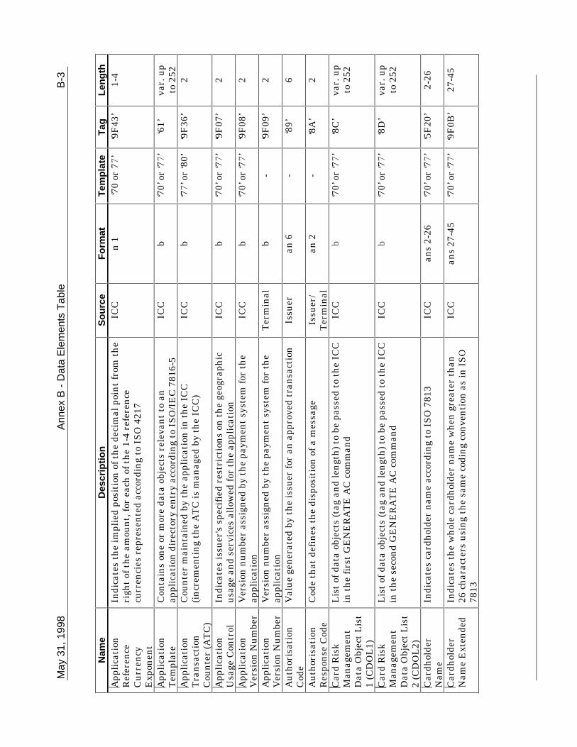
May
31,
199
8A
nnex
B -
Dat
a E
lem
ents
Tab
leB
-3
Nam
eD
escr
ipti
on
So
urc
eF
orm
atT
emp
late
Tag
Len
gth
App
lica
tion
Ref
eren
ceC
urr
ency
Exp
onen
t
Indi
cate
s th
e im
plie
d po
siti
on o
f th
e de
cim
al p
oin
t fr
om t
he
righ
t of
th
e am
oun
t, f
or e
ach
of
the
1-4
refe
ren
cecu
rren
cies
rep
rese
nte
d ac
cord
ing
to I
SO
421
7
ICC
n 1
‘70
or 7
7’‘9
F43
’1-
4
App
lica
tion
Tem
plat
eC
onta
ins
one
or m
ore
data
obj
ects
rel
evan
t to
an
appl
icat
ion
dir
ecto
ry e
ntr
y ac
cord
ing
to I
SO
/IE
C 7
816-
5IC
Cb
‘70’
or
‘77’
‘61’
var.
up
to 2
52A
ppli
cati
onT
ran
sact
ion
Cou
nte
r (A
TC
)
Cou
nte
r m
ain
tain
ed b
y th
e ap
plic
atio
n in
th
e IC
C(i
ncr
emen
tin
g th
e A
TC
is m
anag
ed b
y th
e IC
C)
ICC
b‘7
7’ o
r ‘8
0’‘9
F36
’2
App
lica
tion
Usa
ge C
ontr
olIn
dica
tes
issu
er's
spe
cifi
ed r
estr
icti
ons
on t
he
geog
raph
icu
sage
an
d se
rvic
es a
llow
ed f
or t
he
appl
icat
ion
ICC
b‘7
0’ o
r ‘7
7’‘9
F07
’2
App
lica
tion
Ver
sion
Nu
mbe
rV
ersi
on n
um
ber
assi
gned
by
the
paym
ent
syst
em f
or t
he
appl
icat
ion
ICC
b‘7
0’ o
r ‘7
7’‘9
F08
’2
App
lica
tion
Ver
sion
Nu
mbe
rV
ersi
on n
um
ber
assi
gned
by
the
paym
ent
syst
em f
or t
he
appl
icat
ion
Ter
min
alb
-‘9
F09
’2
Au
thor
isat
ion
Cod
eV
alu
e ge
ner
ated
by
the
issu
er f
or a
n a
ppro
ved
tran
sact
ion
Issu
eran
6-
‘89’
6
Au
thor
isat
ion
Res
pon
se C
ode
Cod
e th
at d
efin
es t
he
disp
osit
ion
of
a m
essa
geIs
suer
/T
erm
inal
an 2
-‘8
A’
2
Car
d R
isk
Man
agem
ent
Dat
a O
bjec
t L
ist
1 (C
DO
L1)
Lis
t of
dat
a ob
ject
s (t
ag a
nd
len
gth
) to
be
pass
ed t
o th
e IC
Cin
th
e fi
rst
GE
NE
RA
TE
AC
com
man
dIC
Cb
‘70’
or
‘77’
‘8C
’va
r. u
pto
252
Car
d R
isk
Man
agem
ent
Dat
a O
bjec
t L
ist
2 (C
DO
L2)
Lis
t of
dat
a ob
ject
s (t
ag a
nd
len
gth
) to
be
pass
ed t
o th
e IC
Cin
th
e se
con
d G
EN
ER
AT
E A
C c
omm
and
ICC
b‘7
0’ o
r ‘7
7’‘8
D’
var.
up
to 2
52
Car
dhol
der
Nam
eIn
dica
tes
card
hol
der
nam
e ac
cord
ing
to I
SO
781
3IC
Can
s 2-
26‘7
0’ o
r ‘7
7’‘5
F20
’2-
26
Car
dhol
der
Nam
e E
xten
ded
Indi
cate
s th
e w
hol
e ca
rdh
olde
r n
ame
wh
en g
reat
er t
han
26 c
har
acte
rs u
sin
g th
e sa
me
codi
ng
con
ven
tion
as
in I
SO
7813
ICC
ans
27-4
5‘7
0’ o
r ‘7
7’‘9
F0B
’27
-45

B-4
Ann
ex
B -
Dat
a E
lem
ents
Tab
leM
ay 3
1, 1
998
Nam
eD
escr
ipti
on
So
urc
eF
orm
atT
emp
late
Tag
Len
gth
Car
dhol
der
Ver
ific
atio
nM
eth
od (
CV
M)
Lis
t
Iden
tifi
es a
met
hod
of
veri
fica
tion
of
the
card
hol
der
supp
orte
d by
th
e ap
plic
atio
nIC
Cb
‘70’
or
‘77’
‘8E
’va
r. u
pto
252
Car
dhol
der
Ver
ific
atio
nM
eth
od (
CV
M)
Res
ult
s
Indi
cate
s th
e re
sult
s of
th
e la
st C
VM
per
form
edT
erm
inal
b-
‘9F
34’
3
Cer
tifi
cati
onA
uth
orit
y P
ubl
icK
ey I
nde
x
Iden
tifi
es t
he
cert
ific
atio
n a
uth
orit
y's
publ
ic k
ey in
con
jun
ctio
n w
ith
th
e R
IDIC
Cb
‘70’
or
‘77’
‘8F
’1
Cer
tifi
cati
onA
uth
orit
y P
ubl
icK
ey I
nde
x
Iden
tifi
es t
he
cert
ific
atio
n a
uth
orit
y's
publ
ic k
ey in
con
jun
ctio
n w
ith
th
e R
IDT
erm
inal
b-
‘9F
22’
1
Com
man
dT
empl
ate
Iden
tifi
es t
he
data
fie
ld o
f a
com
man
d m
essa
geT
erm
inal
b‘8
3’va
r.
Com
man
d to
Per
form
Ser
ies
of b
ytes
to
be d
eliv
ered
by
the
term
inal
to
the
ICC
as a
com
man
d A
PD
U f
or t
he
purp
ose
of s
elec
tin
g ei
ther
aD
DF
or
an A
DF
.
ICC
b‘6
1’‘5
2’va
r. u
pto
239
Cry
ptog
ram
Info
rmat
ion
Dat
a
Indi
cate
s th
e ty
pe o
f cr
ypto
gram
an
d th
e ac
tion
s to
be
perf
orm
ed b
y th
e te
rmin
alIC
Cb
‘77’
or
‘80’
‘9F
27’
1
Dat
aA
uth
enti
cati
onC
ode
An
issu
er a
ssig
ned
val
ue
that
is r
etai
ned
by
the
term
inal
duri
ng
the
veri
fica
tion
pro
cess
of
the
Sig
ned
Sta
tic
App
lica
tion
Dat
a
ICC
b‘9
F45
’2
Ded
icat
ed F
ile
(DF
) N
ame
Iden
tifi
es t
he
nam
e of
th
e D
F a
s de
scri
bed
in I
SO
/IE
C78
16-4
ICC
b‘6
F’
‘84’
5-16
Dir
ecto
ryD
efin
itio
n F
ile
(DD
F)
Nam
e
Iden
tifi
es t
he
nam
e of
a D
F a
ssoc
iate
d w
ith
a d
irec
tory
ICC
b‘6
1’‘9
D’
5-16
Dir
ecto
ryD
iscr
etio
nar
yT
empl
ate
Issu
er d
iscr
etio
nar
y pa
rt o
f th
e di
rect
ory
acco
rdin
g to
ISO
/IE
C 7
816-
5IC
Cva
r.‘6
1’‘7
3’va
r. u
pto
252

May
31,
199
8A
nnex
B -
Dat
a E
lem
ents
Tab
leB
-5
Nam
eD
escr
ipti
on
So
urc
eF
orm
atT
emp
late
Tag
Len
gth
Dyn
amic
Dat
aA
uth
enti
cati
onD
ata
Obj
ect
Lis
t(D
DO
L)
Lis
t of
dat
a ob
ject
s (t
ag a
nd
len
gth
) to
be
pass
ed t
o th
e IC
Cin
th
e IN
TE
RN
AL
AU
TH
EN
TIC
AT
E c
omm
and
ICC
b‘7
0’ o
r ‘7
7’‘9
F49
’u
p to
252
Fil
e C
ontr
olIn
form
atio
n(F
CI)
Iss
uer
Dis
cret
ion
ary
Dat
a
Issu
er d
iscr
etio
nar
y pa
rt o
f th
e F
CI
ICC
var.
‘A5’
‘BF
0C’
var.
up
to 2
22
Fil
e C
ontr
olIn
form
atio
n(F
CI)
Pro
prie
tary
Tem
plat
e
Iden
tifi
es t
he
data
obj
ect
prop
riet
ary
to t
his
spe
cifi
cati
onin
th
e F
CI
tem
plat
e ac
cord
ing
to I
SO
/IE
C 7
816-
4IC
Cva
r.‘6
F’
‘A5’
var.
Fil
e C
ontr
olIn
form
atio
n(F
CI)
Tem
plat
e
Iden
tifi
es t
he
FC
I te
mpl
ate
acco
rdin
g to
IS
O/I
EC
781
6-4
ICC
var.
-‘6
F’
var.
up
to 2
52
ICC
Dyn
amic
Nu
mbe
rT
ime-
vari
ant
nu
mbe
r ge
ner
ated
by
the
ICC
, to
be c
aptu
red
by t
he
term
inal
ICC
b‘9
F4C
’2-
8
Inte
grat
edC
ircu
it C
ard
(IC
C)
PIN
En
ciph
erm
ent
Pu
blic
Key
Cer
tifi
cate
ICC
PIN
En
ciph
erm
ent
Pu
blic
Key
cer
tifi
ed b
y th
e is
suer
ICC
b‘7
0’ o
r ‘7
7’‘9
F2D
’N
I
Inte
grat
edC
ircu
it C
ard
(IC
C)
PIN
En
ciph
erm
ent
Pu
blic
Key
Exp
onen
t
ICC
PIN
En
ciph
erm
ent
Pu
blic
Key
Exp
onen
t u
sed
for
PIN
enci
pher
men
tIC
Cb
‘70’
or
‘77’
‘9F
2E’
1 or
3

B-6
Ann
ex
B -
Dat
a E
lem
ents
Tab
leM
ay 3
1, 1
998
Nam
eD
escr
ipti
on
So
urc
eF
orm
atT
emp
late
Tag
Len
gth
Inte
grat
edC
ircu
it C
ard
(IC
C)
PIN
En
ciph
erm
ent
Pu
blic
Key
Rem
ain
der
Rem
ain
ing
digi
ts o
f th
e IC
C P
IN E
nci
pher
men
t P
ubl
ic K
eyM
odu
lus
ICC
b‘7
0’ o
r ‘7
7’‘9
F2F
’N
PE
− N
I
+ 42
Inte
grat
edC
ircu
it C
ard
(IC
C)
Pu
blic
Key
Cer
tifi
cate
ICC
Pu
blic
Key
cer
tifi
ed b
y th
e is
suer
ICC
b‘7
0’ o
r ‘7
7’‘9
F46
’N
I
Inte
grat
edC
ircu
it C
ard
(IC
C)
Pu
blic
Key
Exp
onen
t
ICC
Pu
blic
Key
Exp
onen
t u
sed
for
the
veri
fica
tion
of
the
Sig
ned
Dyn
amic
App
lica
tion
Dat
aIC
Cb
‘70’
or
‘77’
‘9F
47’
1 to
3
Inte
grat
edC
ircu
it C
ard
(IC
C)
Pu
blic
Key
Rem
ain
der
Rem
ain
ing
digi
ts o
f th
e IC
C P
ubl
ic K
ey M
odu
lus
ICC
b‘7
0’ o
r ‘7
7’‘9
F48
’N
IC −
NI
+ 42
Inte
rfac
e D
evic
e(I
FD
) S
eria
lN
um
ber
Un
iqu
e an
d pe
rman
ent
seri
al n
um
ber
assi
gned
to
the
IFD
by t
he
man
ufa
ctu
rer
Ter
min
alan
8-
‘9F
1E’
8
Issu
er A
ctio
nC
ode
- D
efau
ltS
peci
fies
th
e is
suer
's c
ondi
tion
s th
at c
ause
a t
ran
sact
ion
to
be r
ejec
ted
if it
mig
ht
hav
e be
en a
ppro
ved
onli
ne,
bu
t th
ete
rmin
al is
un
able
to
proc
ess
the
tran
sact
ion
on
lin
e
ICC
b‘7
0’ o
r ‘7
7’‘9
F0D
’5
Issu
er A
ctio
nC
ode
- D
enia
lS
peci
fies
th
e is
suer
's c
ondi
tion
s th
at c
ause
th
e de
nia
l of
atr
ansa
ctio
n w
ith
out
atte
mpt
to
go o
nli
ne
ICC
b‘7
0’ o
r ‘7
7’‘9
F0E
’5
Issu
er A
ctio
nC
ode
- O
nli
ne
Spe
cifi
es t
he
issu
er's
con
diti
ons
that
cau
se a
tra
nsa
ctio
n t
obe
tra
nsm
itte
d on
lin
eIC
Cb
‘70’
or
‘77’
‘9F
0F’
5
Issu
erA
ppli
cati
on D
ata
Con
tain
s pr
opri
etar
y ap
plic
atio
n d
ata
for
tran
smis
sion
to
the
issu
er in
an
on
lin
e tr
ansa
ctio
nIC
Cb
‘77’
or
‘80’
‘9F
10’
var.
up
to 3
2Is
suer
Au
then
tica
tion
Dat
a
Dat
a se
nt
to t
he
ICC
for
on
lin
e is
suer
au
then
tica
tion
Issu
erb
-‘9
1’8-
16

May
31,
199
8A
nnex
B -
Dat
a E
lem
ents
Tab
leB
-7
Nam
eD
escr
ipti
on
So
urc
eF
orm
atT
emp
late
Tag
Len
gth
Issu
er C
ode
Tab
le I
nde
xIn
dica
tes
the
code
tab
le a
ccor
din
g to
IS
O 8
859
for
disp
layi
ng
the
App
lica
tion
Pre
ferr
ed N
ame
ICC
n 2
‘A5’
‘9F
11’
1
Issu
er C
oun
try
Cod
eIn
dica
tes
the
cou
ntr
y of
th
e is
suer
acc
ordi
ng
to I
SO
316
6IC
Cn
3‘7
0’ o
r ‘7
7’‘5
F28
’2
Issu
er P
ubl
icK
ey C
erti
fica
teIs
suer
pu
blic
key
cer
tifi
ed b
y a
cert
ific
atio
n a
uth
orit
yIC
Cb
‘70’
or
‘77’
‘90’
NC
A
Issu
er P
ubl
icK
ey E
xpon
ent
Issu
er p
ubl
ic k
ey e
xpon
ent
use
d fo
r th
e ve
rifi
cati
on o
f th
eS
ign
ed S
tati
c A
ppli
cati
on D
ata
and
the
ICC
Pu
blic
Key
Cer
tifi
cate
ICC
b‘7
0’ o
r ‘7
7’‘9
F32
’1
to 3
Issu
er P
ubl
icK
ey R
emai
nde
rR
emai
nin
g di
gits
of
the
Issu
er P
ubl
ic K
ey M
odu
lus
ICC
b‘7
0’ o
r ‘7
7’‘9
2’N
I − N
CA
+ 36
Issu
er S
crip
tC
omm
and
Con
tain
s a
com
man
d fo
r tr
ansm
issi
on t
o th
e IC
CIs
suer
b‘7
1’ o
r ‘7
2’‘8
6’va
r. u
pto
261
Issu
er S
crip
tId
enti
fier
Iden
tifi
cati
on o
f th
e Is
suer
Scr
ipt
Issu
erb
‘71’
or
‘72’
‘9F
18’
4
Issu
er S
crip
tT
empl
ate
1C
onta
ins
prop
riet
ary
issu
er d
ata
for
tran
smis
sion
to
the
ICC
bef
ore
the
seco
nd
GE
NE
RA
TE
AC
com
man
dIs
suer
b-
‘71’
var.
Issu
er S
crip
tT
empl
ate
2C
onta
ins
prop
riet
ary
issu
er d
ata
for
tran
smis
sion
to
the
ICC
aft
er t
he
seco
nd
GE
NE
RA
TE
AC
com
man
dIs
suer
b-
‘72’
var.
Lan
guag
eP
refe
ren
ce1-
4 la
ngu
ages
sto
red
in o
rder
of
pref
eren
ce, e
ach
repr
esen
ted
by 2
alp
hab
etic
al c
har
acte
rs a
ccor
din
g to
IS
O63
9
ICC
an 2
‘A5’
‘5F
2D’
2-8
Las
t O
nli
ne
App
lica
tion
Tra
nsa
ctio
nC
oun
ter
(AT
C)
Reg
iste
r
AT
C v
alu
e of
th
e la
st t
ran
sact
ion
th
at w
ent
onli
ne
ICC
b-
‘9F
13’
2
Low
erC
onse
cuti
veO
ffli
ne
Lim
it
Issu
er-s
peci
fied
pre
fere
nce
for
th
e m
axim
um
nu
mbe
r of
con
secu
tive
off
lin
e tr
ansa
ctio
ns
for
this
IC
C a
ppli
cati
onal
low
ed in
a t
erm
inal
wit
h o
nli
ne
capa
bili
ty
ICC
b‘7
0’ o
r ‘7
7’‘9
F14
’1
Mer
chan
tC
ateg
ory
Cod
eC
lass
ifie
s th
e ty
pe o
f bu
sin
ess
bein
g do
ne
by t
he
mer
chan
t,re
pres
ente
d ac
cord
ing
to I
SO
858
3:19
93 f
or C
ard
Acc
epto
rB
usi
nes
s C
ode
Ter
min
aln
4-
‘9F
15’
2
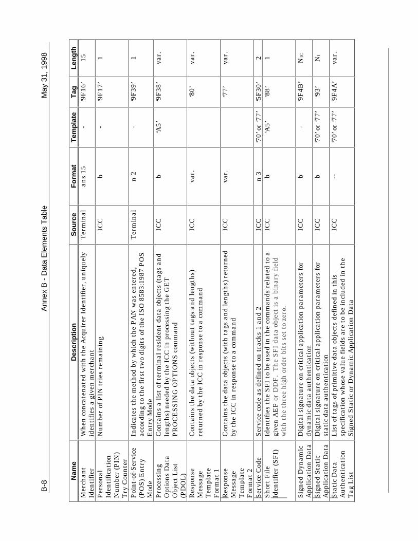
B-8
Ann
ex
B -
Dat
a E
lem
ents
Tab
leM
ay 3
1, 1
998
Nam
eD
escr
ipti
on
So
urc
eF
orm
atT
emp
late
Tag
Len
gth
Mer
chan
tId
enti
fier
Wh
en c
onca
ten
ated
wit
h t
he
Acq
uir
er I
den
tifi
er, u
niq
uel
yid
enti
fies
a g
iven
mer
chan
tT
erm
inal
ans
15-
‘9F
16’
15
Per
son
alId
enti
fica
tion
Nu
mbe
r (P
IN)
Try
Cou
nte
r
Nu
mbe
r of
PIN
tri
es r
emai
nin
gIC
Cb
-‘9
F17
’1
Poi
nt-
of-S
ervi
ce(P
OS
) E
ntr
yM
ode
Indi
cate
s th
e m
eth
od b
y w
hic
h t
he
PA
N w
as e
nte
red,
acco
rdin
g to
th
e fi
rst
two
digi
ts o
f th
e IS
O 8
583:
1987
PO
SE
ntr
y M
ode
Ter
min
aln
2-
‘9F
39’
1
Pro
cess
ing
Opt
ion
s D
ata
Obj
ect
Lis
t(P
DO
L)
Con
tain
s a
list
of
term
inal
res
iden
t da
ta o
bjec
ts (
tags
an
dle
ngt
hs)
nee
ded
by t
he
ICC
in p
roce
ssin
g th
e G
ET
PR
OC
ES
SIN
G O
PT
ION
S c
omm
and
ICC
b‘A
5’‘9
F38
’va
r.
Res
pon
seM
essa
geT
empl
ate
For
mat
1
Con
tain
s th
e da
ta o
bjec
ts (
wit
hou
t ta
gs a
nd
len
gth
s)re
turn
ed b
y th
e IC
C in
res
pon
se t
o a
com
man
dIC
Cva
r.‘8
0’va
r.
Res
pon
seM
essa
geT
empl
ate
For
mat
2
Con
tain
s th
e da
ta o
bjec
ts (
wit
h t
ags
and
len
gth
s) r
etu
rned
by t
he
ICC
in r
espo
nse
to
a co
mm
and
ICC
var.
‘77’
var.
Ser
vice
Cod
eS
ervi
ce c
ode
as d
efin
ed o
n t
rack
s 1
and
2IC
Cn
3‘7
0’ o
r ‘7
7’‘5
F30
’2
Sh
ort
Fil
eId
enti
fier
(S
FI)
Iden
tifi
es t
he
SF
I to
be
use
d in
th
e co
mm
ands
rel
ated
to
agi
ven
AE
F o
r D
DF
. T
he
SF
I da
ta o
bjec
t is
a b
inar
y fi
eld
wit
h t
he
thre
e h
igh
ord
er b
its
set
to z
ero.
ICC
b‘A
5’‘8
8’1
Sig
ned
Dyn
amic
App
lica
tion
Dat
aD
igit
al s
ign
atu
re o
n c
riti
cal a
ppli
cati
on p
aram
eter
s fo
rdy
nam
ic d
ata
auth
enti
cati
onIC
Cb
-‘9
F4B
’N
IC
Sig
ned
Sta
tic
App
lica
tion
Dat
aD
igit
al s
ign
atu
re o
n c
riti
cal a
ppli
cati
on p
aram
eter
s fo
rst
atic
dat
a au
then
tica
tion
ICC
b‘7
0’ o
r ‘7
7’‘9
3’N
I
Sta
tic
Dat
aA
uth
enti
cati
onT
ag L
ist
Lis
t of
tag
s of
pri
mit
ive
data
obj
ects
def
ined
in t
his
spec
ific
atio
n w
hos
e va
lue
fiel
ds a
re t
o be
incl
ude
d in
th
eS
ign
ed S
tati
c or
Dyn
amic
App
lica
tion
Dat
a
ICC
--‘7
0’ o
r ‘7
7’‘9
F4A
’va
r.

May
31,
199
8A
nnex
B -
Dat
a E
lem
ents
Tab
leB
-9
Nam
eD
escr
ipti
on
So
urc
eF
orm
atT
emp
late
Tag
Len
gth
Ter
min
alC
apab
ilit
ies
Indi
cate
s th
e ca
rd d
ata
inpu
t, C
VM
, an
d se
curi
tyca
pabi
liti
es o
f th
e te
rmin
alT
erm
inal
b-
‘9F
33’
3
Ter
min
alC
oun
try
Cod
eIn
dica
tes
the
cou
ntr
y of
th
e te
rmin
al, r
epre
sen
ted
acco
rdin
g to
IS
O 3
166
Ter
min
aln
3-
‘9F
1A’
2
Ter
min
al F
loor
Lim
itIn
dica
tes
the
floo
r li
mit
in t
he
term
inal
in c
onju
nct
ion
wit
hth
e A
IDT
erm
inal
b‘9
F1B
’4
Ter
min
alId
enti
fica
tion
Des
ign
ates
th
e u
niq
ue
loca
tion
of
a te
rmin
al a
t a
mer
chan
tT
erm
inal
an 8
-‘9
F1C
’8
Ter
min
al R
isk
Man
agem
ent
Dat
a
App
lica
tion
-spe
cifi
c va
lue
use
d by
th
e ca
rd f
or r
isk
man
agem
ent
purp
oses
Ter
min
alb
-‘9
F1D
’1-
8
Ter
min
al T
ype
Indi
cate
s th
e en
viro
nm
ent
of t
he
term
inal
, its
com
mu
nic
atio
ns
capa
bili
ty, a
nd
its
oper
atio
nal
con
trol
Ter
min
aln
2-
‘9F
35’
1
Ter
min
alV
erif
icat
ion
Res
ult
s
Sta
tus
of t
he
diff
eren
t fu
nct
ion
s as
see
n f
rom
th
e te
rmin
alT
erm
inal
b-
‘95’
5
Tra
ck 1
Dis
cret
ion
ary
Dat
a
Dis
cret
ion
ary
part
of
trac
k 1
acco
rdin
g to
IS
O/I
EC
781
3IC
Can
s‘7
0’ o
r ‘7
7’‘9
F1F
’va
r.
Tra
ck 2
Dis
cret
ion
ary
Dat
a
Dis
cret
ion
ary
part
of
trac
k 2
acco
rdin
g to
IS
O/I
EC
781
3IC
Ccn
‘70’
or
‘77’
‘9F
20’
var.

B-1
0A
nne
x B
- D
ata
Ele
men
ts T
able
May
31,
199
8
Nam
eD
escr
ipti
on
So
urc
eF
orm
atT
emp
late
Tag
Len
gth
Tra
ck 2
Equ
ival
ent
Dat
aC
onta
ins
the
data
ele
men
ts o
f th
e tr
ack
2 ac
cord
ing
toIS
O/I
EC
781
3, e
xclu
din
g st
art
sen
tin
el, e
nd
sen
tin
el, a
nd
LR
C, a
s fo
llow
s:
Pri
mar
y A
ccou
nt
Nu
mbe
r
Fie
ld S
epar
ator
(hex
. ‘D
’)
Exp
irat
ion
Dat
e (Y
YM
M)
Ser
vice
Cod
e
Dis
cret
ion
ary
Dat
a(de
fin
e by
indi
vidu
al p
aym
ent
syst
ems)
Pad
wit
h h
ex. ‘
FF
’ if
nee
ded
to e
nsu
re w
hol
e by
tes
ICC
b
n, v
ar. u
p to
19
b n 4
n 3
n, v
ar.
b
‘70’
or
‘77’
‘57’
var.
up
to 1
9
Tra
nsa
ctio
nC
erti
fica
te D
ata
Obj
ect
Lis
t(T
DO
L)
Lis
t of
dat
a ob
ject
s (t
ag a
nd
len
gth
) to
be
use
d by
th
ete
rmin
al in
gen
erat
ing
the
TC
Has
h V
alu
eIC
Cb
‘70’
or
‘77’
‘97’
var.
up
to 2
52
Tra
nsa
ctio
nC
erti
fica
te (
TC
)H
ash
Val
ue
Res
ult
of
a h
ash
fu
nct
ion
spe
cifi
ed in
An
nex
F3
of t
his
spec
ific
atio
nT
erm
inal
b-
‘98’
20
Tra
nsa
ctio
nC
urr
ency
Cod
eIn
dica
tes
the
curr
ency
cod
e of
th
e tr
ansa
ctio
n a
ccor
din
g to
ISO
421
7T
erm
inal
n 3
-‘5
F2A
’2
Tra
nsa
ctio
nC
urr
ency
Exp
onen
t
Indi
cate
s th
e im
plie
d po
siti
on o
f th
e de
cim
al p
oin
t fr
om t
he
righ
t of
th
e tr
ansa
ctio
n a
mou
nt
repr
esen
ted
acco
rdin
g to
ISO
421
7
Ter
min
aln
1-
‘5F
36’
1
Tra
nsa
ctio
nD
ate
Loc
al d
ate
that
th
e tr
ansa
ctio
n w
as a
uth
oris
edT
erm
inal
n 6
YY
MM
DD
-‘9
A’
3
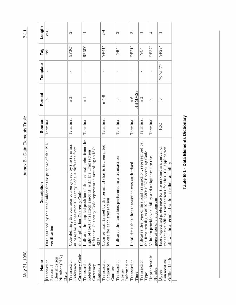
May
31,
199
8A
nnex
B -
Dat
a E
lem
ents
Tab
leB
-11
Nam
eD
escr
ipti
on
So
urc
eF
orm
atT
emp
late
Tag
Len
gth
Tra
nsa
ctio
nP
erso
nal
Iden
tifi
cati
onN
um
ber
(PIN
)D
ata
Dat
a en
tere
d by
th
e ca
rdh
olde
r fo
r th
e pu
rpos
e of
th
e P
INve
rifi
cati
onT
erm
inal
b-
‘99’
var.
Tra
nsa
ctio
nR
efer
ence
Cu
rren
cy C
ode
Cod
e de
fin
ing
the
com
mon
cu
rren
cy u
sed
by t
he
term
inal
in c
ase
the
Tra
nsa
ctio
n C
urr
ency
Cod
e is
dif
fere
nt
from
the
App
lica
tion
Cu
rren
cy C
ode
Ter
min
aln
3-
‘9F
3C’
2
Tra
nsa
ctio
nR
efer
ence
Cu
rren
cyE
xpon
ent
Indi
cate
s th
e im
plie
d po
siti
on o
f th
e de
cim
al p
oin
t fr
om t
he
righ
t of
th
e tr
ansa
ctio
n a
mou
nt,
wit
h t
he
Tra
nsa
ctio
nR
efer
ence
Cu
rren
cy C
ode
repr
esen
ted
acco
rdin
g to
IS
O42
17
Ter
min
aln
1-
‘9F
3D’
1
Tra
nsa
ctio
nS
equ
ence
Cou
nte
r
Cou
nte
r m
ain
tain
ed b
y th
e te
rmin
al t
hat
is in
crem
ente
dby
on
e fo
r ea
ch t
ran
sact
ion
Ter
min
aln
4-8
-‘9
F41
’2-
4
Tra
nsa
ctio
nS
tatu
sIn
form
atio
n
Indi
cate
s th
e fu
nct
ion
s pe
rfor
med
in a
tra
nsa
ctio
nT
erm
inal
b-
‘9B
’2
Tra
nsa
ctio
nT
ime
Loc
al t
ime
that
th
e tr
ansa
ctio
n w
as a
uth
oris
edT
erm
inal
n 6
HH
MM
SS
-‘9
F21
’3
Tra
nsa
ctio
nT
ype
Indi
cate
s th
e ty
pe o
f fi
nan
cial
tra
nsa
ctio
n, r
epre
sen
ted
byth
e fi
rst
two
digi
ts o
f IS
O 8
583:
1987
Pro
cess
ing
Cod
eT
erm
inal
n 2
-‘9
C’
1
Un
pred
icta
ble
Nu
mbe
rV
alu
e to
pro
vide
var
iabi
lity
an
d u
niq
uen
ess
to t
he
gen
erat
ion
of
a cr
ypto
gram
Ter
min
alb
-‘9
F37
’4
Upp
erC
onse
cuti
veO
ffli
ne
Lim
it
Issu
er-s
peci
fied
pre
fere
nce
for
th
e m
axim
um
nu
mbe
r of
con
secu
tive
off
lin
e tr
ansa
ctio
ns
for
this
IC
C a
ppli
cati
onal
low
ed in
a t
erm
inal
wit
hou
t on
lin
e ca
pabi
lity
ICC
b‘7
0’ o
r ‘7
7’‘9
F23
’1
Tab
le B
-1 -
Dat
a E
lem
ents
Dic
tio
nar
y

B-1
2A
nne
x B
- D
ata
Ele
men
ts T
able
May
31,
199
8
Wh
en t
he
len
gth
def
ined
for
th
e da
ta o
bjec
t is
gre
ater
th
an t
he
len
gth
of
the
actu
al d
ata,
th
e fo
llow
ing
rule
s ap
ply:
• A
dat
a el
emen
t in
for
mat
n is
rig
ht
just
ifie
d an
d pa
dded
wit
h le
adin
g h
exad
ecim
al z
eroe
s •
A d
ata
elem
ent
in f
orm
at c
n is
left
just
ifie
d an
d pa
dded
wit
h t
rail
ing
hex
adec
imal
‘F’s
• A
dat
a el
emen
t in
for
mat
an
is le
ft ju
stif
ied
and
padd
ed w
ith
tra
ilin
g h
exad
ecim
al z
eroe
s •
A d
ata
elem
ent
in f
orm
at a
ns
is le
ft ju
stif
ied
and
padd
ed w
ith
tra
ilin
g h
exad
ecim
al z
eroe
s
Wh
en d
ata
is m
oved
fro
m o
ne
enti
ty t
o an
oth
er (
for
exam
ple,
car
d to
ter
min
al),
it s
hal
l alw
ays
be p
asse
d in
ord
er f
rom
hig
hor
der
to lo
w o
rder
, reg
ardl
ess
of h
ow it
is in
tern
ally
sto
red.
Th
e sa
me
rule
app
lies
wh
en c
onca
ten
atin
g da
ta.
Not
e: D
ata
that
can
occ
ur
in t
empl
ate
‘70’
or
‘77’
can
nev
er o
ccu
r in
bot
h.

May 31, 1998 Annex B - Data Elements Table B-13
The tags allocated to the data elements are according to Table B-2:
Name Template TagApplication Identifier (AID) ‘61’ ‘4F’Application Label ‘61’ ‘50’Command to Perform ‘61’ ‘52’Track 2 Equivalent Data ‘70’ or ‘77’ ‘57’Application Primary Account Number (PAN) ‘70’ or ‘77’ ‘5A’Cardholder Name ‘70’ or ‘77’ ‘5F20’Application Expiration Date ‘70’ or ‘77’ ‘5F24’Application Effective Date ‘70’ or ‘77’ ‘5F25’Issuer Country Code ‘70’ or ‘77’ ‘5F28’Transaction Currency Code − ‘5F2A’Language Preference ‘A5’ ‘5F2D’Service Code ‘70’ or ‘77’ ‘5F30’Application Primary Account Number (PAN) SequenceNumber
‘70’ or ‘77’ ‘5F34’
Transaction Currency Exponent − ‘5F36’Application Template ‘70’ or ‘77’ ‘61’File Control Information (FCI) Template − ‘6F’Application Elementary File (AEF) Data Template − ‘70’Issuer Script Template 1 − ‘71’Issuer Script Template 2 − ‘72’Directory Discretionary Template ‘61’ ‘73’Response Message Template Format 2 − ‘77’Response Message Template Format 1 − ‘80’Amount, Authorised (Binary) − ‘81’Application Interchange Profile ‘77’ or ‘80’ ‘82’Command Template − ‘83’Dedicated File (DF) Name ‘6F’ ‘84’Issuer Script Command ‘71’ or ‘72’ ‘86’Application Priority Indicator ‘61’ or ‘A5’ ‘87’Short File Identifier (SFI) ‘A5’ ‘88’Authorisation Code − ‘89’Authorisation Response Code − ‘8A’Card Risk Management Data Object List 1 (CDOL1) ‘70’ or ‘77’ ‘8C’Card Risk Management Data Object List 2 (CDOL2) ‘70’ or ‘77’ ‘8D’Cardholder Verification Method (CVM) List ‘70’ or ‘77’ ‘8E’Certification Authority Public Key Index ‘70’ or ‘77’ ‘8F’Issuer Public Key Certificate ‘70’ or ‘77’ ‘90’Issuer Authentication Data − ‘91’Issuer Public Key Remainder ‘70’ or ‘77’ ‘92’Signed Static Application Data ‘70’ or ‘77’ ‘93’Application File Locator (AFL) ‘77’ or ‘80’ ‘94’Terminal Verification Results − ‘95’Transaction Certificate Data Object List (TDOL) ‘70’ or ‘77’ ‘97’Transaction Certificate (TC) Hash Value − ‘98’Transaction Personal Identification Number (PIN) Data − ‘99’Transaction Date − ‘9A’

B-14 Annex B - Data Elements Table May 31, 1998
Name Template TagTransaction Status Information − ‘9B’Transaction Type − ‘9C’Directory Definition File (DDF) Name ‘61’ ‘9D’Acquirer Identifier − ‘9F01’Amount, Authorised (Numeric) − ‘9F02’Amount, Other (Numeric) − ‘9F03’Amount, Other (Binary) − ‘9F04’Application Discretionary Data ‘70’ or ‘77’ ‘9F05’Application Identifier (AID) − ‘9F06’Application Usage Control ‘70’ or ‘77’ ‘9F07’Application Version Number ‘70’ or ‘77’ ‘9F08’Application Version Number − ‘9F09’Cardholder Name -Extended ‘70’ or ‘77’ ‘9F0B’Issuer Action Code - Default ‘70’ or ‘77’ ‘9F0D’Issuer Action Code - Denial ‘70’ or ‘77’ ‘9F0E’Issuer Action Code - Online ‘70’ or ‘77’ ‘9F0F’Issuer Application Data ‘77’ or ‘80’ ‘9F10’Issuer Code Table Index ‘A5’ ‘9F11’Application Preferred Name ‘61’ ‘9F12’Last Online Application Transaction Counter (ATC)Register
− ‘9F13’
Lower Consecutive Offline Limit ‘70’ or ‘77’ ‘9F14’Merchant Category Code − ‘9F15’Merchant Identifier − ‘9F16’Personal Identification Number (PIN) Try Counter − ‘9F17’Issuer Script Identifier ‘71’ or ‘72’ ‘9F18’Terminal Country Code − ‘9F1A’Terminal Floor Limit − ‘9F1B’Terminal Identification − ‘9F1C’Terminal Risk Management Data − ‘9F1D’Interface Device (IFD) Serial Number − ‘9F1E’Track 1 Discretionary Data ‘70’ or ‘77’ ‘9F1F’Track 2 Discretionary Data ‘70’ or ‘77’ ‘9F20’Transaction Time − ‘9F21’Certification Authority Public Key Index − ‘9F22’Upper Consecutive Offline Limit ‘70’ or ‘77’ ‘9F23’Application Cryptogram ‘77’ or ‘80’ ‘9F26’Cryptogram Information Data ‘77’ or ‘80’ ‘9F27’ICC PIN Encipherment Public Key Certificate ‘70’ or ‘77’ ‘9F2D’ICC PIN Encipherment Public Key Exponent ‘70’ or ‘77’ ‘9F2E’ICC PIN Encipherment Public Key Remainder ‘70’ or ‘77’ ‘9F2F’Issuer Public Key Exponent ‘70’ or ‘77’ ‘9F32’Terminal Capabilities − ‘9F33’Cardholder Verification Method (CVM) Results − ‘9F34’Terminal Type − ‘9F35’Application Transaction Counter (ATC) ‘77’ or ‘80’ ‘9F36’Unpredictable Number − ‘9F37’Processing Options Data Object List (PDOL) ‘A5’ ‘9F38’

May 31, 1998 Annex B - Data Elements Table B-15
Name Template TagPoint-of-Service (POS) Entry Mode − ‘9F39’Amount, Reference Currency − ‘9F3A’Application Reference Currency ‘70’ or ‘77’ ‘9F3B’Transaction Reference Currency − ‘9F3C’Transaction Reference Currency Exponent − ‘9F3D’Additional Terminal Capabilities − ‘9F40’Transaction Sequence Counter − ‘9F41’Application Currency Code ‘70’ or ‘77’ ‘9F42’Application Reference Currency Exponent ‘70’ or ‘77’ ‘9F43’Application Currency Exponent - ‘9F44’Data Authentication Code - ‘9F45’ICC Public Key Certificate ‘70’ or ‘77’ ‘9F46’ICC Public Key Exponent ‘70’ or ‘77’ ‘9F47’ICC Public Key Remainder ‘70’ or ‘77’ ‘9F48’Dynamic Data Object List (DDOL) ‘70’ or ‘77’ ‘9F49’Static Data Authentication Tag List - ‘9F4A’Signed Dynamic Application Data - ‘9F4B’File Control Information (FCI) Proprietary Template ‘6F’ ‘A5’File Control Information (FCI) Issuer DiscretionaryData
‘A5’ ‘BF0C’
Table B-2 - Data Elements Tags

B-16 Annex B - Data Elements Table May 31, 1998
THIS PAGE LEFT INTENTIONALLY BLANK

May 31, 1998 Annex C - Data Objects C-1
Annex C - Data Objects
C1. Coding of BER-TLV Data Objects
As defined in ISO/IEC 8825, a BER-TLV data object consists of 2-3 consecutivefields:
• The tag field (T) consists of one or more consecutive bytes. It codes a class, atype, and a number (see Table C-1). The tag field of the data objects described inthis specification is coded on one or two bytes.
• The length field (L) consists of one or more consecutive bytes. It codes the length
of the following field. The length field of the data objects described in thisspecification is coded on one, two, or three bytes.
• The value field (V) codes the value of the data object. If L = ‘00’, the value field is
not present.
A BER-TLV data object belongs to one of the following two categories:
• A primitive data object where the value field contains a data element for financialtransaction interchange.
• A constructed data object where the value field contains one or more primitive or
constructed data objects. The value field of a constructed data object is called atemplate.
The coding of BER-TLV data objects is defined for as follows.
C1.1 Coding of the Tag Field of BER-TLV Data Objects
The first byte of the tag field of a BER-TLV data object is according to Table C-1:
b8 b7 b6 b5 b4 b3 b2 b1 Meaning0 0 Universal class0 1 Application class1 0 Context-specific class1 1 Private class
0 Primitive data object1 Constructed data object
1 1 1 1 1 See subsequent bytesAny other value Tag number
Table C-1 - Tag Field Structure (First Byte) BER-TLV

C-2 Annex C - Data Objects May 31, 1998
According to ISO/IEC 8825, Table C-2 defines the coding rules of the subsequentbytes of a BER-TLV tag when tag numbers ≥ 31 are used (that is, bits b5 - b1 of thefirst byte equal ‘11111’).
b8 b7 b6 b5 b4 b3 b2 b1 Meaning1 Another byte follows0 Last tag byte
Any value > 0 (Part of) tag number
Table C-2 - Tag Field Structure (Subsequent Bytes) BER-TLV
The coding of the tag field of a BER-TLV data object is according to the followingrules:
• The following application class templates defined in ISO/IEC 7816 apply: ‘61’ and‘6F.’
• The following range of application class templates is defined in Part II: ‘70’ to
‘7F’. The meaning is then specific to the context of an application according tothis specification. Tags ‘78’, ‘79’, ‘7D’, and ‘7E’ are defined in ISO/IEC 7816-6 andare not used in this specification.
• The application class data objects defined in ISO/IEC 7816 and described in Part
II are used according to the ISO/IEC 7816 definition. • Context-specific class data objects are defined in the context of this specification
or in the context of the template in which they appear. • The coding of primitive context-specific class data objects in the ranges ‘80’ to ‘9E’
and ‘9F00’ to ‘9F4F’ is reserved for this specification. • The coding of primitive context-specific class data objects in the range ‘9F50’ to
‘9F7F’ is reserved for the payment systems. • The coding of primitive and constructed private class data objects is left to the
discretion of the issuer.
C1.2 Coding of the Length Field of BER-TLV Data Objects
The coding of the length field is as follows.
When bit b8 of the most significant byte of the length field is set to 0, the lengthfield consists of only one byte. Bits b7 to b1 code the number of bytes of the valuefield. The length field is within the range 1 to 127.
When bit b8 of the most significant byte of the length field is set to 1, thesubsequent bits b7 to b1 of the most significant byte code the number of subsequentbytes in the length field. The subsequent bytes code an integer representing the

May 31, 1998 Annex C - Data Objects C-3
number of bytes in the value field. For example, three bytes are necessary toexpress up to 65,535 bytes in the value field.
C1.3 Coding of the Value Field of Data Objects
A data element is the value field (V) of a primitive BER-TLV data object. A dataelement is the smallest data field that receives an identifier (a tag).
A primitive data object is structured according to Table C-3:
Tag (T) Length (L) Value (V)
Table C-3 - Primitive BER-TLV Data Object (Data Element)
A constructed BER-TLV data object consists of a tag, a length, and a value fieldcomposed of one or more BER-TLV data objects. A record in an AEF governed bythis specification is a constructed BER-TLV data object. A constructed data object isstructured according to Table C-4:
Tag(T)
Length(L)
Primitive orconstructed BER-TLVdata object number 1
... Primitive or constructedBER-TLV data object
number n
Table C-4 - Constructed BER-TLV Data Object

C-4 Annex C - Data Objects May 31, 1998
THIS PAGE LEFT INTENTIONALLY BLANK

May 31, 1998 Annex D - Examples of Directory Structures D-1
Annex D - Examples of Directory Structures
D1. Examples of Directory Structures
Examples shown in this annex are intended to illustrate some possible logical ICCfile structures. Hierarchies of directory structures are shown, but there is noimplication as to the file hierarchies as defined by ISO.
Figure D-1 illustrates a single application card with only a single level directory. Inthis example, the MF (with file identification of ‘3F00’, as defined by ISO/IEC 7816-4) acts as the only DDF in the card. The MF shall be given the unique paymentsystems name assigned to the first level DDF as defined in Section III-1.2, and theFCI of the MF shall contain the SFI data object.
‘DIR A’ in this example may or may not be the ISO DIR file, but it shall conform tothis specification, including the requirement that it has an SFI in the range 1 to 10.The ISO DIR file has a file identifier of ‘2F00’, which may imply that the SFI is notin the correct range.
MF
ADF
EFEF
DIR A
Figure D-1 - Simplest Card Structure Single Application
Figure D-2 gives an example of a multi-application card with a single directory. Inthis example, the root file (MF) does not support an application complying with thisspecification, and no restrictions are placed on the function of the MF. According toISO/IEC 7816-4, a DIR file may be present but is not used by the applicationselection algorithm defined in Part III. Also note that the directory does not haveentries for all ADFs (ADF2 to ADF5), as ADF5 is omitted. ADF5 can be selectedonly by a terminal that ‘knows’ ADF5 may exist in the card. The manner in whichthe terminal finds ADF5 is outside the scope of this specification.

D-2 Annex D - Examples of Directory Structures May 31, 1998
DDF1
ADF 5ADF 4ADF 3
EFEF
EF
EF
EFEF
DIR A
ADF 2EF
MF
Figure D-2 - Single Level Directory
Figure D-3 is an example of a multi-application card with an n level directorystructure. The first level directory (‘DIR A’) has entries for 2 ADFs − ADF3 andADF4 − and a single DDF − DDF2. The directory attached to DDF2 (‘DIR B’) hasentries for two ADFs − ADF21 and ADF22 − and a single DDF − DDF6. DDF5 hasno entry in the root directory and can be found only by a terminal that ‘knows’ of theexistence of DDF5. The manner in which the terminal finds and selects DDF5 isoutside the scope of this specification, but the directory attached to DF5 (‘DIR C’)may conform to this specification, and, if found by the terminal, may lead theterminal to ADFs such as DF51, DF52, and DF53. DIR D, attached to DDF6, is athird level directory and points to four files (not shown), which may be either ADFsor more DDFs.
DDF1
ADF 53ADF 52ADF 22
ADF 51ADF 21
DDF 5ADF 4ADF 3DDF 2
EF
EFEFEFEFEF EF
EFEF
DIR A
DIR B
DIR C
DDF6
MF
DIR D
Figure D-3 - Third Level Directory

May 31, 1998 Annex E - Security Mechanisms E-1
Annex E - Security Mechanisms
E1. Symmetric Mechanisms
E1.1 Encipherment
The encipherment mechanisms for secure messaging for confidentiality uses a 64-bitblock cipher ALG either in Electronic Codebook (ECB) Mode or in Cipher BlockChaining (CBC) mode.
Encipherment of a message MSG of arbitrary length with Encipherment SessionKey KS takes place in the following steps.
1. Padding and Blocking
• If the message MSG has a length that is not a multiple of 8 bytes, add a ‘80’byte to the right of MSG, and then add the smallest number of ‘00’ bytes tothe right such that the length of resulting message MSG := (MSG || ‘80’ ||‘00’ || ‘00’ || . . . || ‘00’) is a multiple of 8 bytes.
• If the message MSG has a length that is a multiple of 8 bytes, the following
two cases can occur depending on pre-defined rules (see Part IV of thisspecification).
- No padding takes place: MSG := MSG. - MSG is padded to the right with the 8-byte block
(‘80’ || ‘00’ || ‘00’ ||‘00’ || ‘00’ || ‘00’ || ‘00’ || ‘00’)
to obtain MSG.
MSG is then divided into 8-byte blocks X1, X2, . . . , Xk.
2. Cryptogram Computation ECB Mode Encipher the blocks X1, X2, . . . , Xk into the 8-byte blocks Y1, Y2, . . . , Yk with the
block cipher algorithm in ECB mode using the Encipherment Session Key KS.Hence compute for i = 1, 2, . . . , k:
Yi := ALG(KS)[Xi].
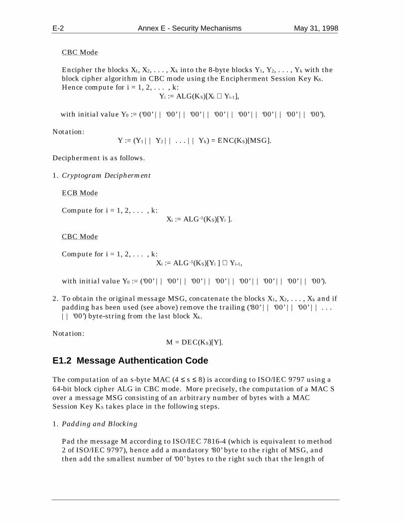
E-2 Annex E - Security Mechanisms May 31, 1998
CBC Mode Encipher the blocks X1, X2, . . . , Xk into the 8-byte blocks Y1, Y2, . . . , Yk with the
block cipher algorithm in CBC mode using the Encipherment Session Key KS.Hence compute for i = 1, 2, . . . , k:
Yi := ALG(KS)[Xi ⊕ Yi-1],
with initial value Y0 := (‘00’ || ‘00’ || ‘00’ || ‘00’ || ‘00’ || ‘00’ || ‘00’ || ‘00’).
Notation:Y := (Y1 || Y2 || . . . || Yk) = ENC(KS)[MSG].
Decipherment is as follows.
1. Cryptogram Decipherment ECB Mode Compute for i = 1, 2, . . . , k:
Xi := ALG-1(KS)[Yi ]. CBC Mode Compute for i = 1, 2, . . . , k:
Xi := ALG-1(KS)[Yi ] ⊕ Yi-1,
with initial value Y0 := (‘00’ || ‘00’ || ‘00’ || ‘00’ || ‘00’ || ‘00’ || ‘00’ || ‘00’). 2. To obtain the original message MSG, concatenate the blocks X1, X2, . . . , Xk and if
padding has been used (see above) remove the trailing (‘80’ || ‘00’ || ‘00’ || . . .|| ‘00’) byte-string from the last block Xk.
Notation:M = DEC(KS)[Y].
E1.2 Message Authentication Code
The computation of an s-byte MAC (4 ≤ s ≤ 8) is according to ISO/IEC 9797 using a64-bit block cipher ALG in CBC mode. More precisely, the computation of a MAC Sover a message MSG consisting of an arbitrary number of bytes with a MACSession Key KS takes place in the following steps.
1. Padding and Blocking Pad the message M according to ISO/IEC 7816-4 (which is equivalent to method
2 of ISO/IEC 9797), hence add a mandatory ‘80’ byte to the right of MSG, andthen add the smallest number of ‘00’ bytes to the right such that the length of

May 31, 1998 Annex E - Security Mechanisms E-3
resulting message MSG := (MSG || ‘80’ || ‘00’ || ‘00’ || . . . || ‘00’) is amultiple of 8 bytes.
MSG is then divided into 8-byte blocks X1, X2, . . . , Xk. 2. MAC Session Key The MAC Session Key KS either consists of only a leftmost key block KS = KSL or
the concatenation of a leftmost and a rightmost key block KS = (KSL || KSR). 3. Cryptogram Computation Process the 8-byte blocks X1, X2, . . . , Xk with the block cipher in CBC mode using
the leftmost MAC Session Key block KSL:
Hi := ALG(KSL)[Xi ⊕ Hi-1], for i = 1, 2, . . . , k.
with initial value H0 := (‘00’ || ‘00’ || ‘00’ || ‘00’ || ‘00’ || ‘00’ || ‘00’ || ‘00’).
• Compute the 8 byte block Hk+1 in one of the following two ways. Accordingto the main process of ISO/IEC 9797:
Hk+1 := Hk.
• According to Optional Process 1 of ISO/IEC 9797:
Hk+1 := ALG(KSL)[ALG-1(KSR)[Hk]].
The MAC S is then equal to the s most significant bytes of Hk+1.
E1.3 Session Key Derivation
Session keys KS for secure messaging for integrity and confidentiality are derivedfrom unique Master Keys KM using diversification data R provided by the receivingentity, hence
KS := F(KM)[R].
To prevent replay attacks, the diversification data R should either be unpredictable,or at least different for each session key derivation.
The only requirement for the diversification function F is that the number ofpossible outputs of the function is sufficiently large and uniformly distributed toprevent an exhaustive key search on the session key.

E-4 Annex E - Security Mechanisms May 31, 1998
E2. Asymmetric Mechanisms
E2.1 Digital Signature Scheme Giving Message Recovery
This section describes the digital signature scheme giving message recovery using ahash function according to ISO/IEC 9796-2. The main features of the scheme arethe following.
• Adding of redundancy in the signature by applying a hash function to the data tobe signed.
• Adding of a header and trailer byte in order to obtain a unique recovery
procedure and to prevent certain attacks as described in the informativereference [2] in Annex G.
E2.1.1 Algorithms
The digital signature scheme uses the following two types of algorithms.
• A reversible asymmetric algorithm consisting of a signing function Sign(SK)[ ]depending on a Private Key SK and a recovery function Recover(PK)[ ] dependingon a Public Key PK. Both functions map N-byte numbers onto N-byte numbersand have the property that
Recover(PK)[Sign(SK)[X]] = X,
for any N-byte number X. • A hashing algorithm Hash[ ] that maps a message of arbitrary length onto an 20-
byte hash code.
E2.1.2 Signature Generation
The computation of a signature S on a message MSG consisting of an arbitrarynumber L of bytes takes place in the following way.
CASE 1: The length L of the message to be signed is at most N − 22 bytes
1. Compute the 20-byte hash value H := Hash[MSG] of the message MSG. 2. Define the (N – 21 – L)-byte block B as follows: B := ‘4A’ if L = N – 22, B := (‘4B’ || ‘BB’ || ‘BB’ || . . . || ‘BB’ || ‘BA’) if L < N – 22. 3. Define the byte E := ‘BC’.

May 31, 1998 Annex E - Security Mechanisms E-5
4. Define the N-byte block X as the concatenation of the blocks B, MSG, H and E,
hence X := (B || MSG || H || E).
5. The digital signature is then defined as the N-byte number
S := Sign(SK)[X].
CASE 2: The length L of the message to be signed is larger than N − 22 bytes
1. Compute the 20-byte hash value H := Hash[MSG] of the message M. 2. Split MSG into two parts MSG =(MSG1 || MSG2), where MSG1 consists of the N
– 22 leftmost (most significant bytes) of MSG and MSG2 of the remaining (leastsignificant) L – N + 22 bytes of MSG.
3. Define the byte B := ‘6A’. 4. Define the byte E := ‘BC’. 5. Define the N-byte block X as the concatenation of the blocks B, MSG1, H and E,
hence X := (B || MSG1 || H || E).
6. The digital signature S is then defined as the N-byte number
S := Sign(SK)[X].
E2.1.3 Signature Verification
Signature verification takes place in the following way.
CASE 1: The length L of the message signed is at most N – 22 bytes
1. Check whether the digital signature S consists of N bytes. 2. Retrieve the N-byte number X from the digital signature S:
X = Recover(PK)[S].
3. Partition X as X = (B || MSG || H || E), where
− B = ‘4A’ or B is a leading byte-string of the form (‘4B’ || ‘BB’ || ‘BB’ || . . . ||‘BB’ || ‘BA’). If none of these cases occur, the signature is rejected.
− H is 20 bytes long.

E-6 Annex E - Security Mechanisms May 31, 1998
− E is one byte long.
− MSG consists of the remaining bytes.
4. Check whether the byte E is equal to ‘BC’. 5. Check whether H = Hash[MSG].
If and only if these checks are correct is the message accepted as genuine.
CASE 2: The length L of the message signed is larger than N – 22 bytes
1. Check whether the digital signature S consists of N bytes. 2. Retrieve the N-byte number X from the digital signature S:
X = Recover(PK)[S].
3. Partition X as X= (B || MSG1 || H || E), where
− B is one byte long.
− H is 20 bytes long.
− E is one byte long.
− MSG1 consists of the remaining N – 22 bytes.
4. Check whether the byte B is equal to ‘6A’. 5. Check whether the byte E is equal to ‘BC’. 6. Compute MSG = (MSG1 || MSG2) and check whether H = Hash[MSG].
If and only if these checks are correct is the message accepted as genuine.

May 31, 1998 Annex F - Approved Cryptographic Algorithms F-1
Annex F - Approved Cryptographic Algorithms
F1. Symmetric Algorithms
F1.1 Data Encryption Standard (DES)
This 64-bit block cipher is the approved algorithm for secure messaging and isstandardised in ISO 8731-1, ISO 8372, and ISO/IEC 10116. More precisely, boththe single DES encipherment and the triple DES encipherment versions describedbelow are approved to be used in the encipherment and MAC mechanisms describedin Annex E.
Triple DES encipherment involves enciphering an 8-byte plaintext block in an 8-byte ciphertext block with a double-length (16-byte) secret key K = (KL || KR) asfollows:
Y = DES(KL)[DES-1(KR)[DES(KL)[X]]].
Decipherment takes place as follows:
X = DES-1(KL)[DES(KR)[DES-1(KL)[Y]]].
F2. Asymmetric Algorithms
F2.1 RSA Algorithm
This reversible algorithm is the approved algorithm for static and dynamic dataauthentication and is used to this aim in the digital signature scheme described inAnnex E (see ISO/IEC 9796-2 and the informative reference [4] in Annex G). Bothodd and even public key exponents are allowed.
The algorithm produces a digital signature whose length equals the size of themodulus used. The mandatory upper bounds for the size of the modulus arespecified in Table F-1.
Description Max. LengthCertification Authority Public Key Modulus 248 bytesIssuer Public Key Modulus 247 bytesICC Public Key Modulus 128 bytes
Table F-1 - Mandatory Upper Bound for the Size in Bytes of the Moduli
Furthermore, the length NCA of the Certification Authority Public Key Modulus, thelength NI of the Issuer Public Key Modulus, and the length NIC of the ICC PublicKey Modulus shall satisfy NIC < NI < NCA.

F-2 Annex F - Approved Cryptographic Algorithms May 31, 1998
In the choice of the lengths of the public key moduli, one should take into accountthe life-time of the keys compared to the expected progress in factoring during thatlife-time. The ranges (upper and lower bounds) for the key lengths mandated byeach of the payment systems are specified in their corresponding proprietaryspecifications.
The length of the Issuer Public Key Exponent and the ICC Public Key Exponent isdetermined by the issuer. The Certification Authority, Issuer and ICC Public KeyExponents shall be equal to 2, 3, or 216 + 1
The Public Key Algorithm Indicator for this digital signature algorithm shall becoded as hexadecimal ‘01’.
The keys and signing and recovery functions for the RSA algorithm are specifiedbelow. The cases for an odd and even public key exponent are consideredseparately. Furthermore, minimum requirements for the key generation process arespecified.
F2.1.1 Odd Public Key Exponent
F2.1.1.1 Keys
The private key SK of the RSA digital signature scheme with an odd public keyexponent e consists of two prime numbers p and q such that p – 1 and q – 1 are co-prime to e and a private exponent d such that
ed ≡ 1 mod (p – 1)(q – 1).
The corresponding public key PK consists of the public key modulus n = pq and thepublic key exponent e.
F2.1.1.2 Signing Function
The signing function for RSA with an odd public key exponent is defined as
S = Sign(SK)[X] := Xd mod n, 0 < X < n, where X is the data to be signed and S the corresponding digital signature.
F2.1.1.3 Recovery Function
The recovery function for RSA with an odd public key exponent is equal to
X = Recover(PK)[S] := Se mod n.

May 31, 1998 Annex F - Approved Cryptographic Algorithms F-3
F2.1.2 Even Public Key Exponent
F2.1.2.1 Keys
The private key SK of the RSA digital signature scheme with an even public keyexponent consists of two prime numbers p and q such that p ≡ 3 mod 8 and q ≡ 7mod 8 and a private exponent d such that
ed ≡ 1 mod 12 lcm(p – 1, q – 1).
Note that the special case e = 2 is better known as the Rabin variant of RSA (seereference [3] in Annex G). In that case, the private exponent is equal to
d = (pq – p – q + 5)/8.
The corresponding public key PK consists of the public key modulus n = pq and thepublic key exponent e.
F2.1.2.2 Signing Function
The signing function for RSA with an even public key exponent is defined as
S = Sign(SK)[X] := Xd mod n, if the Jacobi symbol (X | n) = 1,
S = Sign(SK)[X] := (X/2)d mod n, if the Jacobi symbol (X | n) = -1,
where X is the data to be signed and S the corresponding digital signature.
The data block X is a nonnegative integer less than n with the additional propertythat its least significant byte is equal to ‘BC’. This is to ensure that the recoveryprocess is unique. Note that this is always the case when RSA is used in the digitalsignature scheme described in Annex E2.1.
F2.1.2.3 Recovery Function
The recovery function for RSA with an even public key exponent is as follows.
1. Compute Y := Se mod n. 2. The recovered data is obtained by one of the following cases. (a) If the least significant byte of Y is equal to ‘BC’, X := Y. (b) If the least significant byte of 2Y is equal ‘BC’, X := 2Y. (c) If the least significant byte of n – Y is equal to ‘BC’, X := n – Y. (d) If the least significant byte of 2(n – Y) is equal to ‘BC’, X := 2(n – Y).

F-4 Annex F - Approved Cryptographic Algorithms May 31, 1998
If none of these cases occur, the signature shall be rejected.
F2.1.3 Key Generation
Payment systems and issuers shall be responsible for the security of their respectiveRSA public/private key generation processes. Examples of secure key generationmethods can be found in reference [1] in Annex G.
F3. Hashing Algorithms
F3.1 Secure Hash Algorithm (SHA-1)
This algorithm is standardised as FIPS 180-1.18 SHA-1 takes as input messages ofarbitrary length and produces a 20-byte hash value.
The Hash Algorithm Indicator for this hashing algorithm shall be coded ashexadecimal ‘01’.
18 SHA-1 is also standardised in ISO/IEC 10118-3.

May 31, 1998 Annex G - Informative References G-1
Annex G - Informative References
1. A. Bosselaers and B. Preneel (eds.), Integrity Primitives for Secure InformationSystems, Final Report of the RACE Integrity Primitives Evaluation (RIPE,RACE R1040), LNCS 1007, Springer-Verlag, 1995.
2. L. Guillou, J.-J. Quisquater, M. Walker, P. Landrock, and C. Shaer, ‘Precautions
taken against various potential attacks in ISO/IEC 9796,’ Advances inCryptology – Proceedings of Eurocrypt’90, LNCS 473, I. B. Dåmgard Ed.,Springer-Verlag, 1991, pp. 465-473.
3. M. O. Rabin, Digitalized Signatures and Public-Key Functions as Intractable as
Factorization, Massachusetts Institute of Technology Technical ReportMIT/LCS/TR-212, 1979.
4. R. L. Rivest, A. Shamir, and L. Adleman, ‘A method for obtaining digital
signatures and public key cryptosystems,’ Communications of the ACM, vol. 21,1978, pp. 120-126.
5. G. J. Simmons Ed., Contemporary Cryptology: The Science of Information
Integrity, IEEE Press, Piscataway, N.J., 1992.
Top Related