


Languages
Pages
Legal


-
EMERGY 3000
User Manual
Please read this User Manual first before Operating the System.

-0-
Table of Contents
1. ABOUT THIS MANUAL ......................................................................................................... 1
1.1 Additional Information .......................................................................................................................... 1
1.2 Symbol Used .......................................................................................................................................... 1
2. PRODUCT OVERVIEW .......................................................................................................... 2
2.1 Appearance and Functions .......................................................................................................................... 2
2.2 Gauge/Charging Indicators and Alarm ......................................................................................................... 4
3. SYSTEM OPERATIONS.......................................................................................................... 6
3.1 Turning On/Off System ......................................................................................................................... 6
3.2 Charging System ................................................................................................................................... 6
3.3 System Outputs ..................................................................................................................................... 8
3.4 Physical Positioning............................................................................................................................... 8
3.5 Apparatus/Equipment/Appliances ....................................................................................................... 9
4. TRANSPORTATION ............................................................................................................ 11
5. STORAGE ........................................................................................................................... 12
6. IN CASE OF EMERGENCY ................................................................................................... 13
7. MAINTENANCE .................................................................................................................. 13
8. WARRANTY........................................................................................................................ 14

-1-
1. About this Manual
This User Manual is for use with EMERGY 3000 . User must refer to the User Manual before using to avoid
abnormal situations.
1.1 Additional Information
(1) The information in this document is subject to change without notice.
(2) Specification of the product can be changed without any notice to customers for the system
improvement.
(3) All rights reserved. Reproduction, adaptation, or translation of this document without prior written
permission is prohibited, except as allowed under the copyright laws.
1.2 Symbol Used
Symbols Meaning Description
DANGER Beware dangerous voltage.
WARNING
It calls attention to a procedure, practice, or the like,
which, if not correctly performed or adhered to, could
result in personal injury.
CAUTION
It calls attention to an operating procedure, or the like,
which, if not correctly performed or adhered to, could
result in damage to or destruction of part or all of the
products.

-2-
2. Product Overview
EMERGY 3000 is All-in-One Energy Storage System that integrate Li-Ion Battery System, Battery
Management System, AC charger, Photovoltaic (PV) charger, DC to AC inverter, System Control into the
compact & portable suitcase.
2.1 Appearance and Functions
Figure 1 illustrates the appearance and key external parts in EMERGY 3000 . The functions of each key parts
are highlighted in Table 1.
Figure 1. Control Panel

-3-
Table 1. Key External Parts and Functions
Item Name Function Notes
1 MSW (MAIN
CONTROL SW)
Switch ON/OFF the system Hard press MSW to toggle system
ON/OFF.
2 AC INLET AC Input connection (Please see paragraph 3.2.1)
3 PV INLET AC Input connection (Please see paragraph 3.2.2)
4 AC OUT SW Switch ON/OFF AC output Hard press AC OUT SW to toggle
AC output ON/OFF.
5 AC OUT AC output(s) AC socket(s) varies with country.
6 DC OUT SW Switch ON/OFF DC output Hard press DC OUT SW to toggle
DC output ON/OFF.
7 5V USB OUT USB Power Sources Total current rated at 2A.
8 GAUGE INDICATOR Display State Of Charge
(SOC) of Li-Ion batteries
(Please see Table 2)
9 CHARGING
INDICATOR
Indicate charging state of the
battery
With a lightening mark under
CHARGING INDICATOR.
(Please see Table 3)
10 SYSTEM INDICATOR System status indication Light up when power is present.
11 AC OUT INDICATOR AC output power indication Light up when AC power is
present.
12 DC OUT INDICATOR DC output power indication Light up when DC power is
present.
13 LIFT HANDLE For Lifting EMERGY 3000 .
14 PULL HANDLE For pulling/ pushing the
system while on wheels.
Not for lifting EMERGY 3000 .
DO NOT use PULL HANDLE, but LIFT HANDLE to lift up EMERGY 3000 to avoid
damage to the system.
-4-
2.2 Gauge/Charging Indicators and Alarm
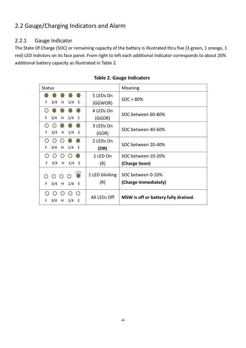
2.2.1 Gauge Indicator The State Of Charge (SOC) or remaining capacity of the battery is illustrated thru five (3 green, 1 orange, 1
red) LED indictors on its face panel. From right to left each additional indicator corresponds to about 20%
additional battery capacity as illustrated in Table 2.
Table 2. Gauge Indicators
Status Meaning
5 LEDs On
(GGWOR) SOC > 80%
4 LEDs On
(GGOR) SOC between 60-80%
3 LEDs On
(GOR) SOC between 40-60%
2 LEDs On
(OR) SOC between 20-40%
1 LED On
(R)
SOC between 10-20%
(Charge Soon)
1 LED blinking
(R)
SOC between 0-10%
(Charge Immediately)
All LEDs Off MSW is off or battery fully drained.
F 3/4 H 1/4 E
F 3/4 H 1/4 E
F 3/4 H 1/4 E
F 3/4 H 1/4 E
F 3/4 H 1/4 E
F 3/4 H 1/4 E
F 3/4 H 1/4 E

-5-
2.2.2 Charging Indicator CHARGING INDICATOR is used to indicate the stage of charging to the battery as illustrated in Table 3.
Table 3. Charging Indicator
Status Meaning
Stay On Charging
Blinking
1. Close to fully charged.
2. Blinking happens if charging current is less than 2A.
3. When closing to fully charged, it is normal whether
CHARGER INDICTOR is blinking or not.
Off
Five GAUGE INDICATORs are all on and CHARGING
INDICATOR is off if the system is fully charged.
2.2.3 Alarm When the remaining battery capacity drops below 15%, an alarm sound- a periodical short buzz will be
initiated to inform user that the battery may run out of energies soon. It should be recharged as soon as
possible to avoid damage batteries.

-6-
3. System Operations
3.1 Turning On/Off System
To turn on the system, firmly press MSW (Main Control Switch) for a light click. SYSTEM INDICATOR and
GAUGE INDICATOR should light up after about 10 seconds delay. This delay is normal and should not be
alarmed.
To turn off the system, press MSW again. All indicating lights will be off. Slight delay in AC OUT INDICATOR
is normal when AC OUT is not or lightly loaded. Pressing MSW will toggle the system status.
3.2 Charging System
3.2.1 AC Charging To perform system charging via AC power source, the following steps are to be followed.
Step 1: Turn on the system by pressing MSW.
Step 2: Connect power cord (IEC320 type) to AC INLET, as illustrated in Figure 2.
Figure 2. AC charging
When EMERGY 3000 is charging, CHARGING INDICATOR will light up CHARGING INDICATOR will turn off
automatically when charging is terminated. The charging time for EMERGY 3000 is around 4-5 hours for a
full charge cycle (from empty to full).
The input source should comply with the input range (100-120Vac or 220-240Vac)
as indicated on AC INLET.
3.2.2 PV Charging

-7-
To perform system charging via PV power source, the following steps are to be followed.
Step 1: Connect PV charging cable adaptor to PV INLET first, as illustrated in Figure 3.
Step 2: Connect MC4 connectors from the cable adaptor to MC4 connectors from PV panels. Use Y
Type MC4 connectors (not provided) for multiple PV panel branches.
Figure 3. PV charging
Step 3: Turn on the system by pressing MSW.
When EMERGY 3000 is charging by PV power, CHARGING INDICATOR will light up. CHARGING INDICATOR
will turn off automatically when charging is terminated.
EMERGY 3000 would take about 5-8 hours for a full charger cycle (from empty to full) when PV power is
greater than 650Wp and it is optimal solar radiation.
Failure to connect the cable adaptor first may cause unexpected electrical shock
from exposed connector pins in the adaptor before follow-up step.
Proper PV configuration should be used to ensure suitable input voltage range for
PV charger of EMERGY 3000 (refer to product specifications). Excessive voltage
level (>200V) may result in damage to PV charger.

-8-
3.3 System Outputs
3.3.1 AC Output AC outlet(s) of EMERGY 3000 provided is (are) also compatible with local electrical plugs. To utilize AC
output, the following steps are to be followed.
Step 1: Turn on the system by pressing MSW.
Step 2: Turn on AC output(s) by pressing AC OUT SW. AC OUT INDICATOR will turn on.
Step 3: Connect power cord of apparatus, equipment or appliance to AC OUT (AC outlet).
To discontinue using AC output, simply remove power cord of load unit from AC OUT or turn off AC output
by pressing AC OUT SW again. AC OUT INDICATOR will turn off.
The voltage and frequency range of the apparatus, equipment or appliance should
comply with the output voltage and frequency range of EMERGY 3000 to avoid
under-performance or damage to the load unit.
3.3.2 DC (USB) Output DC (USB) output is turned on when MSW and DC OUT SW are switched on. When DC OUT SW is turned off,
DC output is also turned off. A total of 2A current is available for the two USB outlets.
3.4 Physical Positioning
EMERGY 3000 is designed to operate in an upright position as illustrated in Figure 4 Stable footing should
be provided when using the system. It is also highly recommended that the two braking mechanisms be
engaged to avoid possible skidding especially when the ground is inclined.
Figure 4. Physical Operating Position
Operations under other positions will add to thermal stresses on the system and
reduce system operating time.

-9-
3.5 Apparatus/Equipment/Appliances
3.5.1 Compatibility Although EMERGY 3000 is designed to operate with most household apparatus/equipment/appliances,
certain loads that require heavy surge current may not operate properly.
A list of apparatus/equipment/appliances that are compatible or incompatible with EMERGY 3000 are
shown in Table 4.
Table 4. Loads Supports
Operate Not Operate
(1) Consumer electronics
Mobile phones, tablets, NBs, PCs, monitors,
projectors, desk-top printer/copier, shredder, etc.
(2) Household appliances
Rice cookers, TVs, refrigerators, hair dryers,
lamps/lights (fluorescent, LED), fans, induction
ranges, irons, dish washers, hair dryer, toasters,
heater, etc.
(3) Industrial equipment
Oscilloscopes, electrical drills/screw drivers,
soldering irons, etc.
Air conditioners, microwave
ovens, office printers/copiers,
coffee makers, vacuum
cleaners, industrial motors,
etc.

-10-
3.5.2 Running Time Estimated run time for a fully charged EMERGY 3000 is shown in Table 5.
Table 5. EMERGY 3000 Run Times for Select Loads
Electrical Equipment Power
Consumption
DP1715JDF
Running Time
DP2615
Running Time
Lighting
Camping Lantern 5W 306.0 hours 468.0 hours
LED Lighting 10W 153.0 hours 234.0 hours
LED Searchlight 30W 51.0 hours 78.0 hours
Fluorescent Lamp 36W 42.5 hours 65.0 hours
Home
Appliance
Radio 10W 153.0 hours 234.0 hours
Electric Fan 66W 23.2 hours 35.5 hours
Refrigerator 130W 11.8 hours 18.0 hours
42” LCD TV 200W 7.7 hours 11.7 hours
Sound System 200W 7.7 hours 11.7 hours
Toasters 600W 2.6 hours 3.9 hours
Electric Pot 800W 1.9 hours 2.9 hours
Heater 1,000W 1.5 hours 2.3 hours
Induction Cooker 1,200W 1.3 hours 2.0 hours
3C
Smart Phone 2W 765.0 hours 1,170.0 hours
Tablet 20W 76.5 hours 117.0 hours
Note Book 40W 38.3 hours 58.5 hours
Projector 200W 7.7 hours 11.7 hours
Desktop PC & Monitor 310W 4.9 hours 7.5 hours
Laser Printer 500W 3.1 hours 4.7 hours
-11-
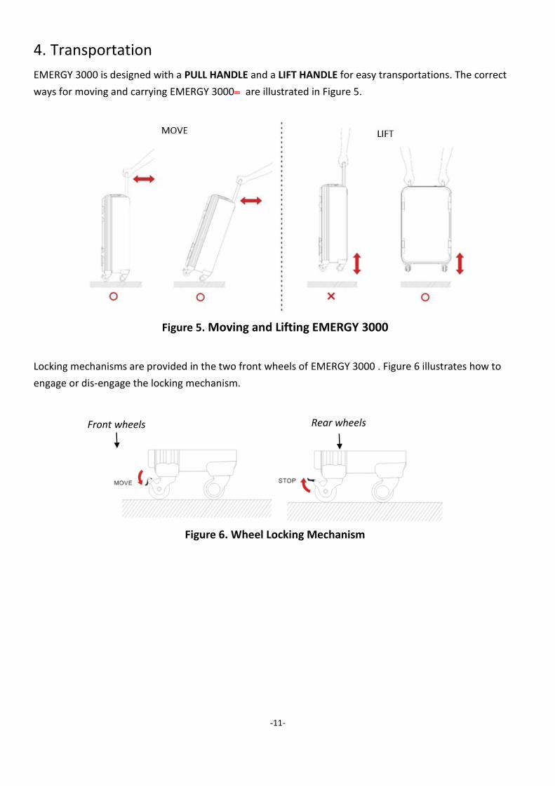
4. Transportation
EMERGY 3000 is designed with a PULL HANDLE and a LIFT HANDLE for easy transportations. The correct
ways for moving and carrying EMERGY 3000 are illustrated in Figure 5.
Figure 5. Moving and Lifting EMERGY 3000
Locking mechanisms are provided in the two front wheels of EMERGY 3000 . Figure 6 illustrates how to
engage or dis-engage the locking mechanism.
Figure 6. Wheel Locking Mechanism
Front wheels Rear wheels

-12-
When transporting the system in a vehicle, EMERGY 3000 should be laid flat on HEAT SINK side, as
illustrated in Figure 7.
Figure 7. Physical Positioning for Transportation in a Vehicle
5. Storage
It is highly recommended that EMERGY 3000 is turned off (MSW off) when it is not in use to conserve the
battery energies. Failure to do so may deplete the battery energies prematurely and reduce system’s
availability.
In extreme case, the battery may be over-discharged rendering expensive replacement of the battery.
The following practices should be exercised when storing EMERGY 3000 .
(1) Charge EMERGY 3000 to 50%-70% capacity. (For short term storage while preparing for usage,
charge the system to full capacity.)
(2) Turn off MSW. All panel lights should be off.
(3) Place the system in solid footing to avoid skidding or falling. Engage the locking mechanism in the
front wheels.
(4) Store EMERGY 3000 in a cool, dry, airy place and away from fire or heat sources.

-13-
6. In Case of Emergency
In the case of unlikely situation when smokes rise from the system, under the premise of no immediate
danger, the following actions can be taken to reduce possible damages.
Evacuate the premises immediately if imminent danger is sensed.
(1) Avoid inhaling the smokes from the system.
(2) Hard press MSW to shut the system off.
(3) Unplug input cables followed by output cables.
(4) Move the system to an open area.
(5) If fire results, use sand or dry-powder/ CO2 extinguisher to extinguish fire.
7. Maintenance
Regular maintenance of EMERGY 3000 is not necessary except maintaining sufficient charge state of the
batteries to avoid possible over-discharge during storage especially after usage. The appearance and
surface can be cleaned with a damped cloth with water.
DO NOT attempt to repair EMERGY 3000 yourself. All units should be returned to
authorized vendor or repair center for repair. Unauthorized opening of the system
case will void product warranty and may expose the user to dangerous high
voltage.
DO NOT spray water directly onto the system to clean the unit. Water sips thru
connector openings on the face panel and the power inlets may accumulate inside
the system and cause damages.
For outdoor applications connector plugs (provided with the system) should be
used to cover the unused inlets and outlets to prevent unexpected rain which may
cause water sipping into the system. Remove the system from the rain
immediately.

-14-
8. Warranty
EMERGY 3000 is warranted against defects in material and workmanship for a period of one (DP2615
Model) or two (DP1715JDF Model) years after purchase to the original owner. It is at the Manufacturer’s
sole discretion whether to repair or to replace system assembly part(s) found to be defective.
Transportation to the service center or the factory is the responsibility of the purchaser.
This warranty is void for products repaired or altered by the customer or any unauthorized person or entity.
This warranty also does not cover damages caused by improper use, accidents, and natural disasters.
-15-
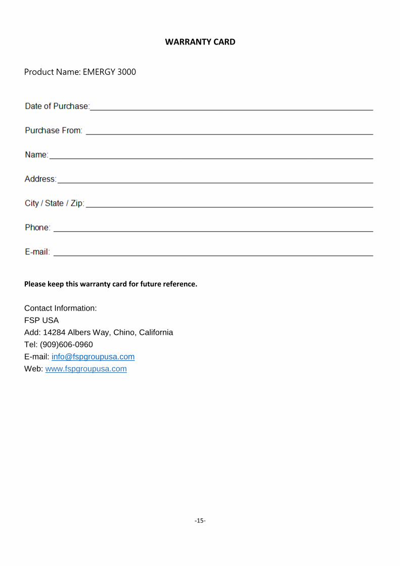
WARRANTY CARD
Product Name: EMERGY 3000
Please keep this warranty card for future reference.
Contact Information:
FSP USA
Add: 14284 Albers Way, Chino, California
Tel: (909)606-0960
E-mail: [email protected]
Web: www.fspgroupusa.com

-
Contact Information:
FSP USA
Add: 14284 Albers Way, Chino, California
Tel: (909)606-0960
E-mail: [email protected]
Web: www.fspgroupusa.com
Top Related