


Languages
Pages
Legal

Department of Electrical EngineeringUniversity of Arkansas
ELEG 5173L Digital Signal Processing
Introduction to TMS320C6713 DSK
Dr. Jingxian Wu
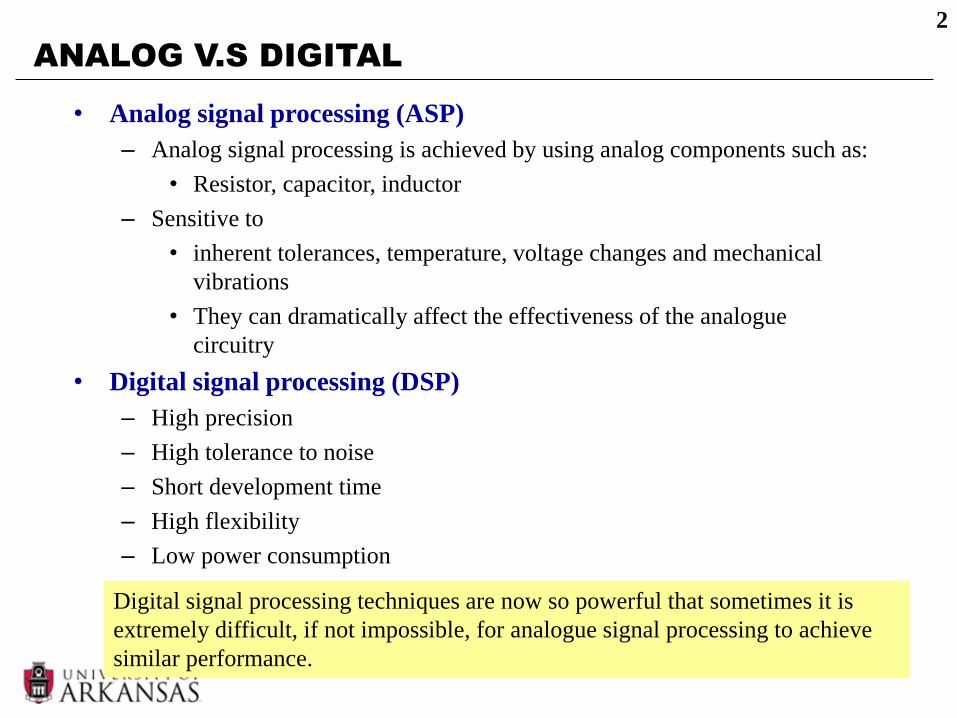
ANALOG V.S DIGITAL
• Analog signal processing (ASP)
– Analog signal processing is achieved by using analog components such as:
• Resistor, capacitor, inductor
– Sensitive to
• inherent tolerances, temperature, voltage changes and mechanical
vibrations
• They can dramatically affect the effectiveness of the analogue
circuitry
• Digital signal processing (DSP)
– High precision
– High tolerance to noise
– Short development time
– High flexibility
– Low power consumption
2
Digital signal processing techniques are now so powerful that sometimes it is
extremely difficult, if not impossible, for analogue signal processing to achieve
similar performance.
3
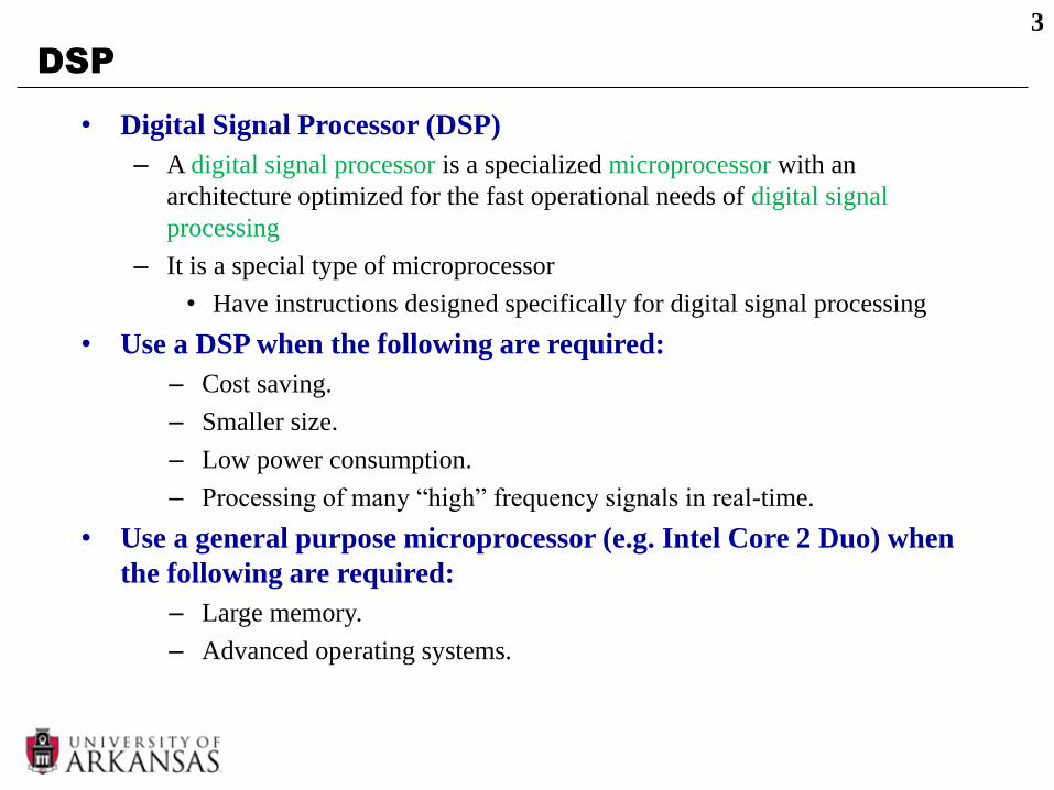
DSP
• Digital Signal Processor (DSP)
– A digital signal processor is a specialized microprocessor with an
architecture optimized for the fast operational needs of digital signal
processing
– It is a special type of microprocessor
• Have instructions designed specifically for digital signal processing
• Use a DSP when the following are required:
– Cost saving.
– Smaller size.
– Low power consumption.
– Processing of many “high” frequency signals in real-time.
• Use a general purpose microprocessor (e.g. Intel Core 2 Duo) when
the following are required:
– Large memory.
– Advanced operating systems.

DSP
• DSP
– The key operation in digital signal processing is sum of products (SOP) or
multiply and accumulation (MAC)
4
Algorithm Equation
Finite Impulse Response Filter
M
k
k knxany
0
)()(
Infinite Impulse Response Filter
N
k
k
M
k
k knybknxany
10
)()()(
Convolution
N
k
knhkxny
0
)()()(
Discrete Fourier Transform
1
0
])/2(exp[)()(
N
n
nkNjnxkX
Discrete Cosine Transform
1
0
122
cos).().(
N
x
xuN
xfucuF

DSP
• DSP are optimized for MAC operations
– Multiplication and addition are done in hardware and in one cycle.
– Example: 4-bit multiply (unsigned).
5
1011
x 1110
1011
x 1110
Hardware Microcode
10011010 0000
1011.
1011..
1011...
10011010
Cycle 1
Cycle 2
Cycle 3
Cycle 4
Cycle 5
DSP general purpose microprocessor
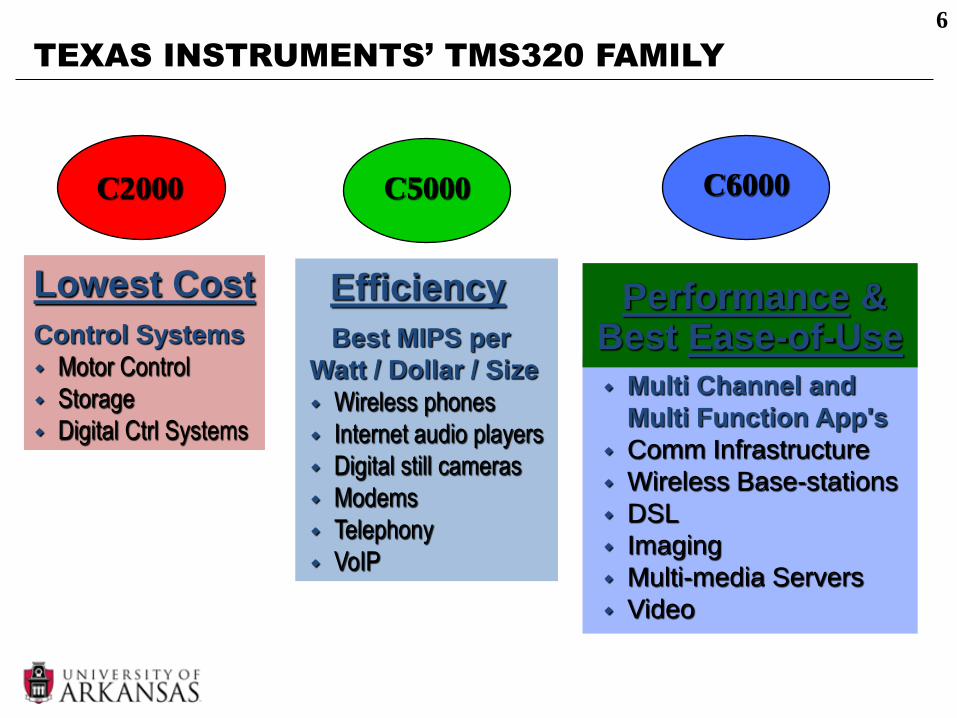
TEXAS INSTRUMENTS’ TMS320 FAMILY
6
Lowest Cost
Control Systems
Motor Control
Storage
Digital Ctrl Systems
C2000 C5000
Efficiency
Best MIPS per
Watt / Dollar / Size
Wireless phones
Internet audio players
Digital still cameras
Modems
Telephony
VoIP
C6000
Multi Channel and
Multi Function App's
Comm Infrastructure
Wireless Base-stations
DSL
Imaging
Multi-media Servers
Video
Performance &Best Ease-of-Use

TMS320C6713
• TMS320C6713
– Very-long-instruction-word (VLIW) architecture
• Suited for numerically intensive algorithms.
– 8 instructions can be fetched per clock cycle
• E.g. clock rate 225 MHz, clock period = 1/225 MHz = 4.44 ns
• 8 instructions can be fetched every 4.44 ns.
– 264 KB internal memory.
– 6 Arithmetic and logic units (ALUs)
– 2 multiplier units
– 32 bit address bus (up to 4 GB memory)
– 2 sets of 32-bit registers
– Capable of both fixed point and floating point processing.
7
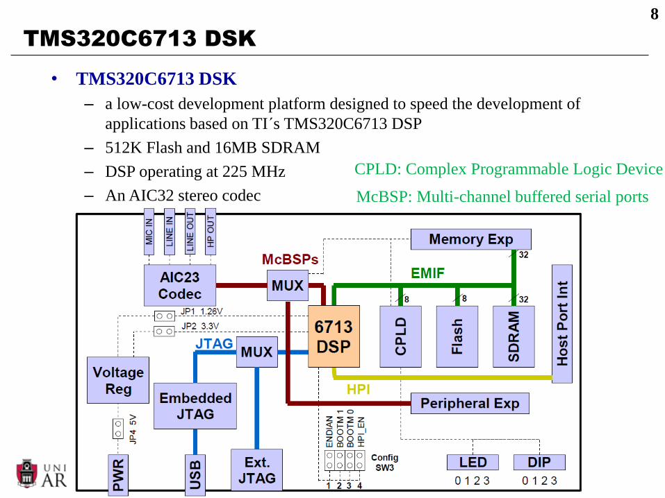
TMS320C6713 DSK
• TMS320C6713 DSK
– a low-cost development platform designed to speed the development of
applications based on TI´s TMS320C6713 DSP
– 512K Flash and 16MB SDRAM
– DSP operating at 225 MHz
– An AIC32 stereo codec
8
McBSP: Multi-channel buffered serial ports
CPLD: Complex Programmable Logic Device
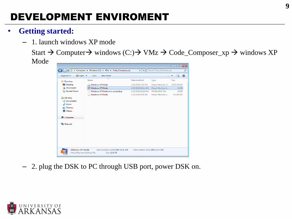
DEVELOPMENT ENVIROMENT
• Getting started:
– 1. launch windows XP mode
Start Computer windows (C:) VMz Code_Composer_xp windows XP
Mode
– 2. plug the DSK to PC through USB port, power DSK on.
9
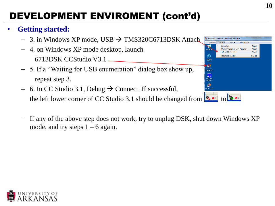
DEVELOPMENT ENVIROMENT (cont’d)
• Getting started:
– 3. in Windows XP mode, USB TMS320C6713DSK Attach
– 4. on Windows XP mode desktop, launch
6713DSK CCStudio V3.1
– 5. If a “Waiting for USB enumeration” dialog box show up,
repeat step 3.
– 6. In CC Studio 3.1, Debug Connect. If successful,
the left lower corner of CC Studio 3.1 should be changed from to
– If any of the above step does not work, try to unplug DSK, shut down Windows XP
mode, and try steps 1 – 6 again.
10

EXAMPLE
• sin8_LED.c
11

EXAMPLE
• sin8_buf.c
– AIC23 will generate an interrupt at every sample instant
– fs = 8KHz: 8,000 interrupts will be generated by the AIC23
– Every time an interrupt is generated, c_int11 will be executed.
12
Top Related