


Languages
Pages
Legal


8/13/2019 Electronic discharge machining
http://slidepdf.com/reader/full/electronic-discharge-machining 1/25
CHAPTER-1
INTRODUCTION
1.1 Introduction
A number of computationally efficient optimization tools are being developed now a day, but the numerical tools for multi-criterion optimization problems have their own
significance. The present work aims beyond the mini-max approaches use for such
optimization problems. In order to ustify the related work, a machining method, known
as !lectric "ischarge #achining $!"#% process has been chosen. The work contained in
this minor proect report covers the relationships establishment between the various input
variables and parameters for the !"# machine. &egression analysis techni'ues have
been adopted to obtain the relationships. (nce the problem of !"# process has been
modeled, it has been tried to ustify the importance of bicriterion approaches in the
manufacturing environment. The results have been obtained for the given set of
constraints and the individual obective functions and are compared to those obtained by
using bicriterion approaches. The generalized genetic algorithms have been used for the
nonlinear obective functions for a given constraints in the form of crisp value bounded
domains. A brief overview of the !lectric discharge machining process is as under.
1.2 Basics of EDM
The use of thermoelectric source of energy in developing the non-traditional techni'ues
has greatly helped in achieving an economic machining of the extremely low
machinability materials and difficult obs. The process of material removal by a
controlled erosion through a series of electric sparks, commonly known as !"#, was
first started in )*+ in &. /hen a discharge takes place between two points of the
anode and cathode, the intense heat generated near the zone melts and evaporates the
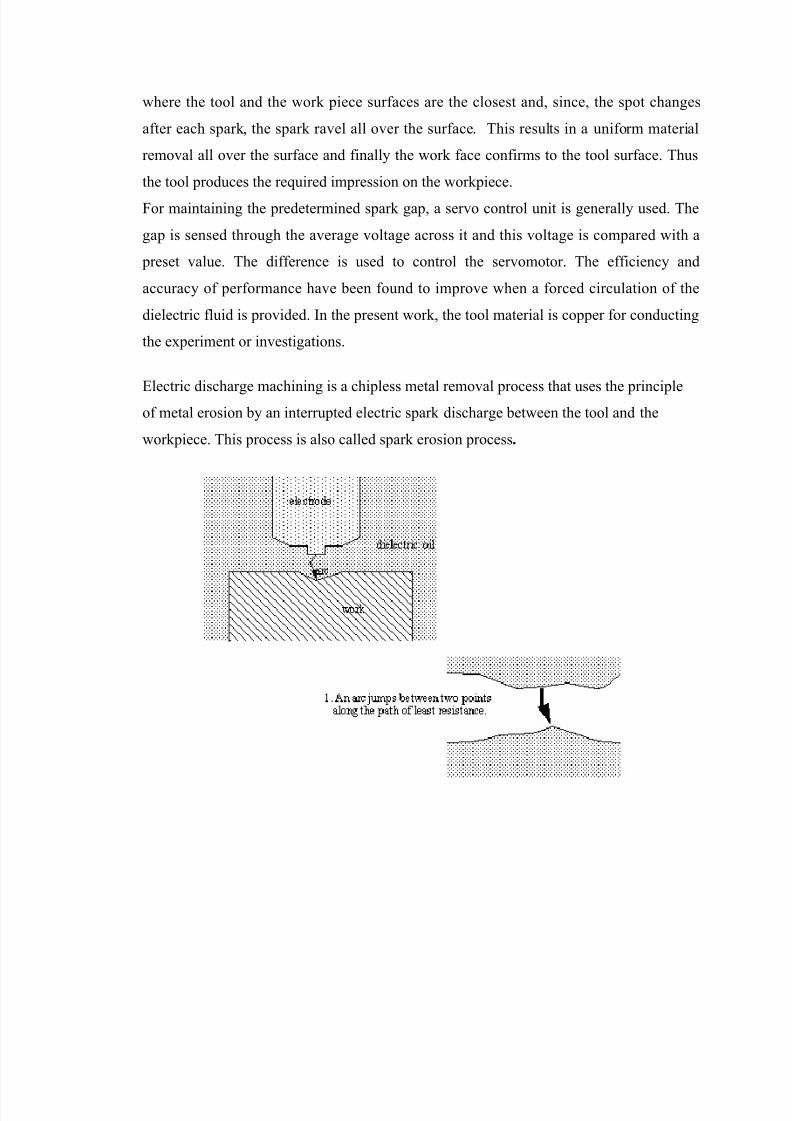
materials in the sparking zone. 0or improving the effectiveness, the workpiece and the
tool are submerged in the "ielectric fluid. The basic !"# process has been shown in
0ig. ).). it has been observed that if both the electrodes are made of the same material,
the electrode connected to the positive terminal generally erodes at faster rate. 0or this
reason, the work piece is generally made the anode. A suitable gap, known as the spark
gap, is maintained between the tool and the workpiece surfaces. The sparks are made to
discharge at a high fre'uency with a suitable source. ince the spark occurs at the spot
8/13/2019 Electronic discharge machining
http://slidepdf.com/reader/full/electronic-discharge-machining 2/25
where the tool and the work piece surfaces are the closest and, since, the spot changes
after each spark, the spark ravel all over the surface. This results in a uniform material
removal all over the surface and finally the work face confirms to the tool surface. Thus
the tool produces the re'uired impression on the workpiece.
0or maintaining the predetermined spark gap, a servo control unit is generally used. The
gap is sensed through the average voltage across it and this voltage is compared with a
preset value. The difference is used to control the servomotor. The efficiency and
accuracy of performance have been found to improve when a forced circulation of the
dielectric fluid is provided. In the present work, the tool material is copper for conducting
the experiment or investigations.
!lectric discharge machining is a chipless metal removal process that uses the principleof metal erosion by an interrupted electric spark discharge between the tool and the
workpiece. This process is also called spark erosion process.

8/13/2019 Electronic discharge machining
http://slidepdf.com/reader/full/electronic-discharge-machining 3/25
Princip! of op!ration
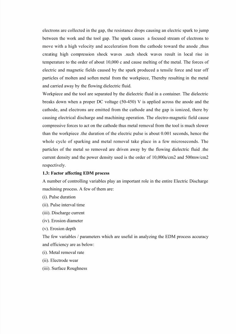
/e know that whenever an arc is caused by an accidental short circuit, pitting erosion
occurs on the surface of the shorted material. !"# also works on the same principle of
erosion by arcing. It involves the controlled erosion of electrically conducting materials
by rapid and repetitive discharge of spark between the electrode tool and workpiece
$hence the name spark erosion% the tool is usually made the cathode and the workpiece
made the anode. The workpiece and tool separated by a small gap and termed as the
sparkgap. The spark gap ranges from 1.112 mm to 1.12mmdepending upon the cutting
action re'uired and the current density, this spark gap is either flooded or immersed in a
dielectric fluid, the spark discharge is produced by the controlled pulsing and direct
current. The fre'uency ranges from a few hundred to several thousand kilohertz with the
application of a suitable voltage across the anode and cathode, electrons are the emitted
from the cathode and cause the ionization of the fluid in the sparkgap, when more
8/13/2019 Electronic discharge machining
http://slidepdf.com/reader/full/electronic-discharge-machining 4/25
electrons are collected in the gap, the resistance drops causing an electric spark to ump
between the work and the tool gap. The spark causes a focused stream of electrons to
move with a high velocity and acceleration from the cathode toward the anode ,thus
creating high compression shock waves .such shock waves result in local rise in
temperature to the order of about )1,111 c and cause melting of the metal. The forces of
electric and magnetic fields caused by the spark produced a tensile force and tear off
particles of molten and soften metal from the workpiece, Thereby resulting in the metal
and carried away by the flowing dielectric fluid.
/orkpiece and the tool are separated by the dielectric fluid in a container. The dielectric
breaks down when a proper "3 voltage $21-+21% 4 is applied across the anode and the
cathode, and electrons are emitted from the cathode and the gap is ionized, there by
causing electrical discharge and machining operation. The electro-magnetic field cause
compressive forces to act on the cathode thus metal removal from the tool is much slower
than the workpiece .the duration of the electric pulse is about 1.11) seconds, hence the
whole cycle of sparking and metal removal take place in a few microseconds. The
particles of the metal so removed are driven away by the flowing dielectric fluid .the
current density and the power density used is the order of )1,111a5cm6 and 211mw5cm6
respectively.
1."# $actor aff!ctin% EDM proc!ss
A number of controlling variables play an important role in the entire !lectric "ischarge
machining process. A few of them are7
$i%. 8ulse duration
$ii%. 8ulse interval time
$iii%. "ischarge current
$iv%. !rosion diameter
$v%. !rosion depth
The few variables 5 parameters which are useful in analyzing the !"# process accuracy
and efficiency are as below7
$i%. #etal removal rate
$ii%. !lectrode wear
$iii%. urface &oughness

8/13/2019 Electronic discharge machining
http://slidepdf.com/reader/full/electronic-discharge-machining 5/25
$iv%. 8ower consumption by the #achine
M!ta r!&o'a rat!
#etal removal rate it is direct proportional to the current density used. it is defined as the
volume of metal removed per unit time per ampere. The metal removal rate in
roughening operations of steel with a graphite electrode 21 A current is about
+11mm5min and with +11A current it is about +911mm5min . :ut for high precision
works with use of high fre'uency $211-)111% k;z and low current $)-6A%, metal removal
rate is as low as 6mm5min.
Accurac(
The accuracy of the process mainly depends on the spark gap. The smaller the gap the
higher is the accuracy, but a smaller gaps leads to a lower working voltage and hence a
slow metal removal rate. Thus an optimum gap is necessary for higher accuracies
tolerances of <-1.12 mm can be obtained in normal !"# operations. In precision
operations, with close control of process variables, tolerance up to <-1.11 mm can be
achieved. !"# also produces taper, overcut and corner radii, which are not desirable.
The taper is of the order of 1.112 to 1.12mm per )1 mm depth. The taper effect reduces
gradually to zero after about =2mm penetration .taper effect can be eliminated by the use
of vacuum flushing of dielectric fluid.
The range of overcut is 2 to )11 microns and depth on the roughening operations .the
effect of corner radii is e'ual to the spark gap. Its value is lower in finishing operations,
where low park gaps are used.
)urfac! finis*
In !"# operations, each electrical spark discharge develops a spherical crater in the
workpiece, as well as in the electrode. The volume of crater is proportional to the energy
in the spark. Thus the depth of the crater is proportional to the energy in the spark. Thus
the depth of the crater on work piece defines the surface finish and it depends upon the
current density, fre'uency and the electrode material. usually high fre'uency and low
current density give better surface finish, the best surface finish on steel is of the order of
1.+ micron $at )111khz >)A%.in a typical no-wear !"# ,the surface finish is about
.6micron $generally roughing operations%

8/13/2019 Electronic discharge machining
http://slidepdf.com/reader/full/electronic-discharge-machining 6/25
H!at !ff!ct!d +on! ,HA
The instant heating and vaporization of metal due to spark, leaves behind a small amount
of molten metal on the machined surface which re-solidifies and due to fast cooling
action of the dielectric fluid forms a hard surface. This becomes the heat affected zone. In
!"# operations .the ;A? is about 6 to )1micron )1 micron deep on the work surface
and its hardness is about @1;&3.the hard surface is a source for thermal stresses ,plastic
deformation and fine cracks at the grain boundaries .the depth of ;A? is small in
finishing operations which can be removed by producing after !"# operations.
Too !!ctrod! /!ar
/hile performing the operations ,the tool gets eroded due to sparking action .so the tool
material should be a material should which is difficult to machine such as a graphite
which goes to vaporization without melting.
/ear ratiomaterial removal from work5material removal from the toolB
Typical electrode materials are,
). 3opper,
6. Tungsten
. Craphite
!lectrode material is selected on the basis of wear ratio, metal removal rate ,cost and ease
of grinding the electrode most commonly used materials may include brass copper
graphite ,al-alloys ,cu-alloys etc. flow hole should be made while making for the
circulation of dielectric flow so as to attain large flow rates at low pressure.

8/13/2019 Electronic discharge machining
http://slidepdf.com/reader/full/electronic-discharge-machining 7/25
8/13/2019 Electronic discharge machining
http://slidepdf.com/reader/full/electronic-discharge-machining 8/25
+. It should be able to deionise immediately after the spark discharge. It should have a
high flash point. It should not emit toxic vapours and should not have unpleasant odours.
2. It should not alter its basic properties under operating conditions of temperature
variations, contamination by metal particles and products of decomposition. It should be
economical for use.
)!!ction of di!!ctric fuid
The main consideration in the selection of a dielectric fluid is the operating conditionsE
the choice of dielectric fluids depends on the size of workpiece, complexity of the shape,
surface finish re'uired and material removal rate. ome of the dielectric fluids a, their
machining rate and wear ratios.
The choice of a particular dielectric fluid depends on the tolerance re'uired, size and
shape of the work material removal rate and the type of electrode. 0or example, white
spirit is used to machine tungsten carbide and metals for with intricate shapes and
re'uiring high surface finish. Cenerally, low viscosity fluids are used for very high
surface finishesE the used dielectric fluid is recirculated and after proper filtering action
remove the metal particles. 0iltering medium like wound cotton yarn cartridge
diatomaceous earth filter are used to remove wastes from the medium for normal
precision works filters better than 6 microns sizes are used.
The commonly used dielectrics are kerosene, paraffin transformer oil or mixture of
various oils.
)par %ap
The spark gap between the tool and the work is in the range of 1.112 to 1.12mm.this gap
depends on the type of tool, work material. "ielectric fluid and the current density used.
:efore solving the optimization problem for this process, some parameters or variables
are generally specified such as erosion diameter, erosion depth, applied working voltage,
dielectric pressure etc. once the operating conditions and workpiece-tasking is defined,
the same machine is to be run for various investigations with in the controlled parameter
variation. The parameter variation ranges are specified in upcoming chapter on problem
formulation and solutions.

8/13/2019 Electronic discharge machining
http://slidepdf.com/reader/full/electronic-discharge-machining 9/25
Ad'anta%!s
!lectrical discharge machining has advantages over other machining techni'ues due to its
ability to create complex and intricate parts with a high degree of accuracy. This process
is able to machine hard materials that other machining processes would have difficulties
with. Another advantage of !"# is its ability to machine parts on an extremely small
scale. /hile using this process, the workpiece is not deformed from impact because there
is no direct contact between the electrode and the material. The workpiece is burr-free
after completion and saved from heat damage because very little is actually generated
during the procedure that would harm the material. As well as dimensional factors of size
and shape, an important consideration before undergoing this procedure is the material of
the workpiece, since the material of the electrode has to be specially matched. ome of
the common applications for !"# include producing plastic molds, die casting dies from
hardened steel and forging dies. (ther purposes include the manufacturing of engine
parts like compressor blades of titanium alloys and nickel based super alloys. Industries
that benefit from the use of the electrical discharge machining process include food and
beverage, automobile, stamping, extruding, defense, electronics, aerospace and medical.
8/13/2019 Electronic discharge machining
http://slidepdf.com/reader/full/electronic-discharge-machining 10/25
CHAPTER 2
ITERATURE RE3IE4
!fforts are being made now a day to solve complex engineering problems through
mathematical algorithms with high computations accuracy. A number of research papers
exist in the literature related to these newly developed optimization techni'ues. I have
tried to use the concept of genetic algorithms for solving the complex formulated
problems of the !lectro "ischarge #achining process. The stress has been given on
understanding the problem from the core and some of the research papers used for
formulation and understanding the problem are outlined as below7
Foopelli, 4 G)H has tried to model and formulate the !lectric "ischarge #achining
process with the optimization of obective functions related to moving traectories of
machine tool electrode. Cradient based methods have been used to optimize the single
obective function variable. A moving frame reference has also been used to locate the
tool electrode at any instant along its traversed traectories.
Fain 4. . G6H has formulated the generalized !lectro "ischarge #achining method with
the limited constraints related to 8ulse interval time and pulse duration. #any operating
variables are considered as parameters with fixed working values over a given erosion
depth and erosion rate on the work piece. The formulated problem has been analysed by
using a simple optimization algorithm by keeping other obective functions unaffected
and the results are concluded to give the suitable operating variable value selection on the
basis of output obtained.
ahng, 3. ; GH states that operating working voltage and the pulse interval plays an
important role in obtaining the re'uired surface finish. The flow movement of the
dielectric fluid controls the homogeneous surface characteristics in the entire !"#
controlled region. The spark gap control has also been explained to obtain the desired
level of surface roughness for a given set of operating variables. 0luttering of the edges in
the !"# region has been investigated for the variation in the controlling parameters.

8/13/2019 Electronic discharge machining
http://slidepdf.com/reader/full/electronic-discharge-machining 11/25
J.3. Jim, ;.;. Ju G2H has specified the basic thumb rules for the analysis of surface
features of !lectro discharge machining process. This paper is mainly meant for skilled
workmanship towards achieving the desired surface characteristics in minimum time and
with safety. The saving of the production cost is ustified for the !"# process carried
out. 3ommon measures and precautions which are helpful in carrying out the !"#
process for efficient operation are also been suggested. This paper is recommended for
peer mainly.
#adhu, 8., Fain, 4. G @ H has developed the governing e'uations for the analysis of
!lectro "ischarge machining process under a controlled environment. A computer
program has also been developed in the form of subroutines for the calculation of
electrode wear rate. #etal removal rate and dielectric material effect on the !"#
process. The results obtained by the formulation used with the help of 'uadratic elements
have shown a good convergence with those obtained by the commercial packages.
8andit, . # G9H ahs stated the critical factors affecting the performance of the !lectro
"ischarge machining process when the workpiece material is 3emented carbide. A
suitable hard alloy material is selected as electrode tool material. And the dielectric fluid
is given turbulent flow in and around the !"# region. The operating variables like 8ulse
duration, "ischarge 3urrent, (perating voltage, 8ulse Interval time and heat dissipation
rate differ in operating ranges considerably as compared to electro discharge machining
of teel alloys. ;owever, it has been claimed that consistency and repeatability of the
machine towards maintaining the minimum deviation in the operating conditions helps a
lot in the #achining accuracy in the process.
8andit, . # G*H has considered the theoretical aspects of the !lectro "ischarge
machining 8rocess. The energy parameters and the #etal removal rate relationships have
been developed for the given set of operating voltages and the dielectric pressure. The
relationships obtained have been used to plot graphs for the variation in the operating
controlling parameters and their effects on the conse'uents such as metal removal rate,
surface roughness and the power consumption by the machine etc. These graphs can be
directly used for the selection of given constrained condition of operating variables for
the desired obectives.

8/13/2019 Electronic discharge machining
http://slidepdf.com/reader/full/electronic-discharge-machining 12/25
&aurkar, .8 ., and ?hu, "G)1H have elaborated a number of alternatives for the
improvement in the electrochemical machining process by changing the sensitivity
parameters and have stated that in comparison to other operating variables, the traectory
of the electrode movement plays a vital role in improving the surface characteristics of
the !3# process.
&aurkar, . 8. has developed a network based flow diagram for the !lectric "ischarge
machining processes. The intermediate processes are shown in the diagram along with
their precedence events and successors. The dependencies have also been evaluated at a
particular instant by assuming some of the operating conditions fixed. The flow diagram
had been used to optimize the !"# process by selecting the independent paths for a
given set of parameter values.
pedding, T.A G))H have used the concept of conformal transformation of the operating
characteristic variables. The variables are parameterized and the parametric
representation of the metal removal rate, surface roughness has been mapped onto
parametric surface. The surface characteristics of the wire3ut !"# process have been
analysed for the sensitivity of the operating variables. The dependencies of the decision
variable on each other are represented and a computation algorithm has been proposed to
evaluate the mapped point for specified surface characteristics onto parametric plane.
pedding, T.A. and /ang, ?.K G)6H has considered the theoretical aspects of the
modelling of the wire3ut !"# process. A user friendly approach has been adopted for
the definition of process parameters and these parameters are compared to other various
ranges of operating variables. The interpretation of output variables variations has been
carried out for the wire 3ut !"# process and the suggested ranges of the input variables
are given for a desired set of output variables in terms of metal removal rate and power
consumption etc.
myers, ., Cuha, A.G) H has stated a practical approach for #achining the :eryllium
3opper alloys as workpiece by !lectro "ischarge #achining process. #ethods have
been suggested for obtaining the desired level of surface characteristics by using this
!"# method. afety precautions and the indicative measures are suggested for the
fruitful implementation of the process. A brief note is also given for specifying the
operating characteristics and safety precautions for the !"# process to be carried out.
8/13/2019 Electronic discharge machining
http://slidepdf.com/reader/full/electronic-discharge-machining 13/25
/ang /.#.G)+H states that spark gap and the controlling parameters for a sensitive !"#
process layout can be controlled in number of ways. A feedback system with real time
stability analysis and process monitoring through digital modern sensors and transducers
can give an efficient responding mechanism for the !"# process control. The author
also states that transducers, circuitry, encoders etc. can be selected to give influence of
simultaneous variation of operating variables and their response data storage facility.
Indurkhya, C has developed an artificial neural network for the entire !lectro "ischarge
#achining process. The relationships between the operating intermediate processes along
with decision variables have been framed. The performance index evaluation for the
!"# process for a given specified crisp sets of the operating variables helps in
understanding the efficiency of the process to be carried out. The performance Index
evaluated by using this method helps in analysing the adverse and positive gradient
effects of the variation in the #etal removal rate, the surface roughness and the power
consumption by the machine.
?hang, : G)2H the report submitted by the author and his team members have calculated
the effect of motion and turbulence level in the dielectric material during various stages
of the electo discharge machining process. The results are tabulated and graphs have
been recommended for use for the machining of steel materials. The effect of the
selection of dielectric fluid has also been analysed for a given set of electrode tool and
material combination.
?hang 3 G)@H and his team members have developed tolerances for the different
machining parameters,the results have recommended for the machining parameters.
?immermann ;. F G)=H. has developed 0uzzy 8rogramming and Jinear 8rogramming
with everal (bective 0unctions.
8/13/2019 Electronic discharge machining
http://slidepdf.com/reader/full/electronic-discharge-machining 14/25
CHAPTER "
METHODO56 ADOPTED
everal multiobective optimization methods are available in the literature including the
weighted multiobective method, Archimedean goal programming, non-Archimedeangoal programming, and the original 3hebyshev goal programming methods. The
weighted multiobective method involves subectivity and bias in specifying the weights
in order to aggregate several non commensurable and conflicting obectives into a single
e'uivalent function. Archimedean and non-Archimedean goal programming methods
suffer from the difficulties in determining the weights for deviation variables within a
lower priorityE and the ranking of the goals in a preemptive preference order. /ith the
original 3hebyshev approach, the final solution could be dictated by a single goal. The
modified 3hebyshev goal programming #3C8 approach helps to avoid the above
difficulties and will be used in this study. It should also be noted that the #3C8 is in fact
a fuzzy programming approach and hence can be used to effectively deal with obectives
that are imprecise or fuzzy in nature, such as the intangible cost mentioned above. The
#3C8 can be implemented using the Jingo software. The procedure is detailed as
follows7
!ach obective function can be represented as an function in terms of minimization or of
maximization type as under.
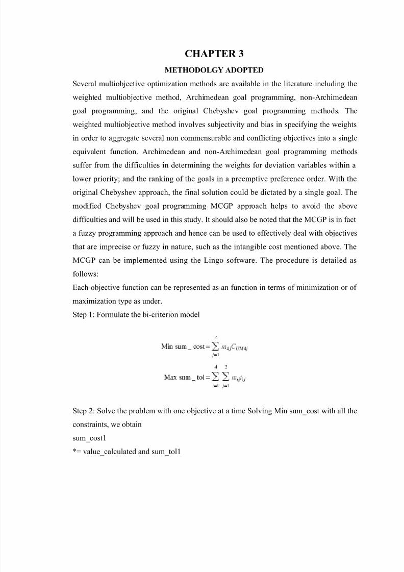
tep )7 0ormulate the bi-criterion model
tep 67 olve the problem with one obective at a time olving #in sumLcost with all the
constraints, we obtain
sumLcost)
M valueLcalculated and sumLtol)
8/13/2019 Electronic discharge machining
http://slidepdf.com/reader/full/electronic-discharge-machining 15/25
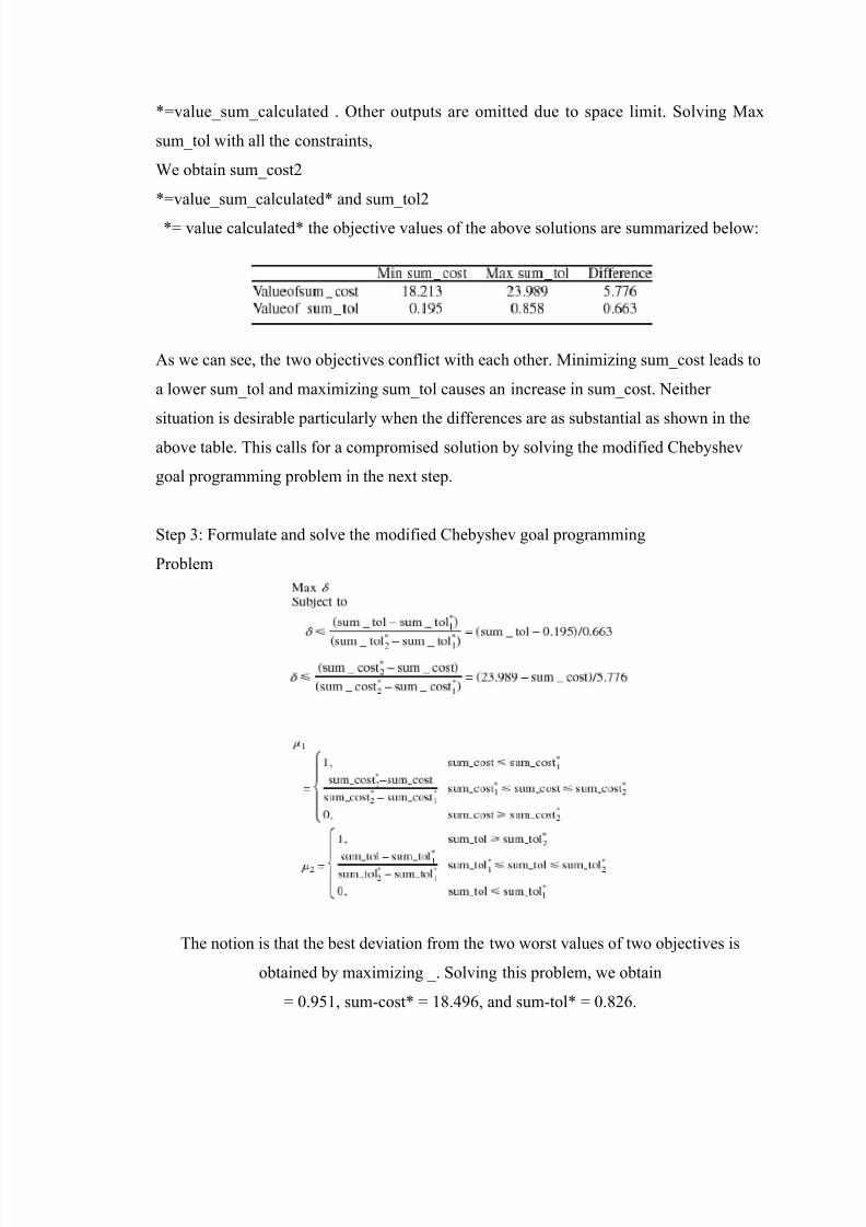
MvalueLsumLcalculated . (ther outputs are omitted due to space limit. olving #ax
sumLtol with all the constraints,
/e obtain sumLcost6
MvalueLsumLcalculatedM and sumLtol6
M value calculatedM the obective values of the above solutions are summarized below7
As we can see, the two obectives conflict with each other. #inimizing sumLcost leads to
a lower sumLtol and maximizing sumLtol causes an increase in sumLcost. Deither
situation is desirable particularly when the differences are as substantial as shown in the
above table. This calls for a compromised solution by solving the modified 3hebyshev
goal programming problem in the next step.
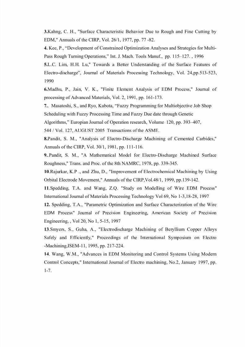
tep 7 0ormulate and solve the modified 3hebyshev goal programming
8roblem
The notion is that the best deviation from the two worst values of two obectives is
obtained by maximizing L. olving this problem, we obtain
1.*2), sum-costM )9.+*@, and sum-tolM 1.96@.

8/13/2019 Electronic discharge machining
http://slidepdf.com/reader/full/electronic-discharge-machining 16/25
CHAPTER 7
$ORMUATION O$ THE EDM PROCE)) PROBEM AND IT) )OUTION
In many engineering activities, it is very difficult to obtain an explicitly or implicitlyformalized description of the system which could them be optimized. &ecently most of
the research work is devoted to the methods for finding a statistically- experimental
model of such systems. These methods are based on the experiments and their aim is to
determine an investigation program which s compromise between a re'uired number of
investigations in real life condition and their informativeness. The data thus obtained are
analyzed by means of regression methods and then the mathematical model of the system
is then obtained. This model describes the functional dependence between input variables
and out variables. The forms of approximation functions can be considered different. 0or
the !"# process formulation same techni'ues have been applied and the relationships
have been developed as specified obective functions in the problem.
In !lectric "ischarge machining process, main input 'uantities are7
a%. 8ulse "uration
b%. 8ulse Interval
c%. Amplitude of "ischarge current
d%. !rosion surface
e%. !rosion depth etc.
/hereas the main output 'uantities are
i%. #etal removal rate
ii%. !lectrode wear
iii%. 8ower consumption
iv%. urface roughness
v%. "imensional shape accuracy of the work piece
A theoretically recommended approach to the problem of finding a mathematical
description of the !"# process would be to carry out investigations in the whole region

8/13/2019 Electronic discharge machining
http://slidepdf.com/reader/full/electronic-discharge-machining 17/25
of the space of input variables. The space of variables can be restricted to the region
which is physically sensible and sets of e'uations are obtained.
These sets of e'uations give a mathematical description of the !"# process which is the
basis for building the optimization model. In the present model, the decision variables are
those input 'uantities whose values are set on the machine i.e. 8ulse duration, 8ulse
interval time and discharge current. If the erosion surface does not change in the
machining process and depth of erosion is also known in advance, these two input
'uantities are treated as parameters.
The choice of the obective and constraint functions depends on the user re'uirement.
The output 'uantities usually chosen as obective functions are7 maximizing metal
removal rate, minimizing tool electrode wear rate.
The surface roughness and the dimension and shape accuracy of the workpiece can be
taken as the third and fourth obective functions in case of the accurate machining. In this
process rough machining has been considered, so these two 'uantities may be considered
as constraints or they may be omitted. imilarly, the power consumption by the machine
may be either a new obective function or the constraint or it may be discarded.
In the problem formulation a particular case of !"# process has been analyzed. It is
granted that cylindrical copper electrode is to be used as a tool and tool steel as the
machining material. It is assumed to have constant dielectric pressure and average
working voltage while taking the experimental readings which are to be used further for
regression analysis.
The (bective 0unctions of the problem formulated after regression analysis of the
investigations are as below
K e)).=++I)).=++<1.16lnTi<1.166lnTo<1.1612lnN<1.16@lngTi-).222<1.1+=lnTo<6.=@lnN<1.12)lngTo-1.)1=-
1.)=+lnN<1.)22lngN-).1@=-1.)6+lngg-1.=+6
O e-9).21*I2.@+-1.+*lnTi-1.2lnTo<1.))*lnN<1.)[email protected])nTo-1.++lnN<1.62lngTo).@1*-
6.1+2lnN<1.61=lngN)6.6)*-1.)=)lngg-.)16
D e-1.@@I).+)-1.1@@lnTi-1.))*lnTo<1.)+lnN<1.12lngTi1.6<1.1=))nTo-1.1+9lnN<1.1.1)@lngTo1.9+2-
1.)*=lnN- 1.129lngN1.22=-1.11lngg1.112
ubected to 3onstraints
Ti P 211 x )1-@ The pulse duration in econds does not exceed

8/13/2019 Electronic discharge machining
http://slidepdf.com/reader/full/electronic-discharge-machining 18/25
Ti Q 6111 x )1-@ These minimum and #aximum Jimits
To Q 621 x )1-@ The pulse Interval time in econds does not exceed
To P )62 x )1-@ These minimum and #aximum Jimits
I Q )69 The "ischarge 3urrent in Amperes does not exceed
I P @+ These minimum and #aximum Jimits
N Q =1 The !rosion "iameter in mm does not exceed
NP 21 These minimum and #aximum Jimits
g Q )1 The !rosion "epth in mm does not exceed
g P 2 These minimum and #aximum Jimits
4 2 R The applied working 4oltage is kept
almost constant
8 @1.9 h8a The "ielectric 8ressure is kept almost constant
and e'ual to this value for a case when cylindrical
3opper electrode is the tool material and Tool
steel is the machined material
This problem is a case of #ulti- 3riteria (ptimization type with different #ini-#ax
constraints and obective 0unctions 3onditions. 0or a given set of constraint each
obective function can be evaluated by using any nonlinear programming techni'ue or by
using Cenetic algorithms. ;owever, in each case there is no guarantee to get optimized
results of the parameters when other obective functions are not taken into account. A
number of some other approaches exist to solve a #ulti-obective function problem but
all of them are either derivative function based or assumes suitable penalty functions for
the account of other obective function.
/hile solving such cases, the approximate solution is achieved but is considerably away
from the exact solutions. The integrated problem is formulated as a bicriterion model to
handle both tangible and intangible costs. The model is solved using a modified
3hebyshev goal programming method to achieve a preferred compromise between the
two conflicting and noncommensurable criteria.

8/13/2019 Electronic discharge machining
http://slidepdf.com/reader/full/electronic-discharge-machining 19/25
In the above problem formulation, it is clear that for a given set of entry constraints
variables, the obective functions are of following types7
$i%. K, #aterial removal rate 7 To be maximized
$ii%. O, !lectrode /ear in percentage 7 To be #inimized
$iii%. D, power consumption in /atts 7 To be #inimized
/hen multi- criteria model is developed, the nature of the obective functions are
conflicting type and the combination of obective 0unction for #etal removal rate with
other two obective functions in terms of electrode wear and power consumption makes
obective function mini-max type.
According to the :i-3riteria #odel formulation to the above problem, such combination
of #ini-#ax type obective functions along with constraints is considered and the
optimal values of the parameters and obective functions are evaluated at particular
instances.
)t!p 17 0ormulation as per bicriterion model
Cas! I7 considering obective functions $i% and $i%
#aximize K e)).=++ I)).=++<1.16lnTi<1.166lnTo<1.1612lnN<1.16@lngTi-).222<1.1+=lnTo<6.=@lnN<1.12)lng
To-1.)1=-1.)=+lnN<1.)22lngN-).1@=-1.)6+lngg-1.=+6
#inimize O e-9).21*I2.@+-1.+*lnTi-1.2lnTo<1.))*lnN<1.)[email protected])nTo-1.++lnN<1.62lng
To).@1*-6.1+2lnN<1.61=lngN)6.6)*-1.)=)lngg-.)16
ubected to 3onstraints
Ti P 211 x )1-@ Ti Q 6111 x )1-@
To Q 621 x )1-@ To P )62 x )1-@
I Q )69 I P @+
N Q =1 NP 21
g Q )1 g P 2
Cas! II# considering obective functions $i% and $iii%
#aximize K e)).=++ I)).=++<1.16lnTi<1.166lnTo<1.1612lnN<[email protected]<1.1+=lnTo<6.=@lnN<1.12)lng
To-1.)1=-1.)=+lnN<1.)22lngN-).1@=-1.)6+lngg-1.=+6
#inimize D e-1.@@I).+)-1.1@@lnTi-1.))*lnTo<1.)+lnN<1.12lngTi1.6<1.1=))nTo-1.1+9lnN<1.1.1)@lng
To1.9+2-1.)*=lnN-1.129lngN1.22=-1.11lngg1.112
ubected to 3onstraints

8/13/2019 Electronic discharge machining
http://slidepdf.com/reader/full/electronic-discharge-machining 20/25
Ti P 211 x )1-@ Ti Q 6111 x )1-@
To Q 621 x )1-@ To P )62 x )1-@
I Q )69 I P @+
N Q =1 NP 21
g Q )1 g P 2
tep 67 olve the problem with one obective at a time
The problem is solved by using generalized genetic algorithm for the given set of
constraints and only one obective function at a time. The values obtained for each case
are tabulated as below7
3ase I
#inimize O, mm #aximize K, mm5min "ifference4alue L#in O 1.)96+*9 1.*9@@=9* 1.91+6*)
4alueLmax K +)9.*=9@+2 *2).2+2@= 26.2@+*663ase II
#inimize D, /att #aximize K, mm5min "ifference
4alueLmin D [email protected]=@2+2 =112.2@=+ +6+).@*19924alueLmax K =6.9*=@2+2 *2).2+2@= 2=9.@+2*)62
As we see the two obectives conflict to each other in each case. #inimize O leads to a
lower value of K while maximizing K leads to an considerable increase in the value of O
in case I. in case II, #inimize D leads to a lower value of K while maximizing K leads to
an considerable increase in the value of D.
Deither solution can be considered desirable particularly when the differences are
substantial as shown in the table above.
This calls for a compromise solution by solving modified 3hebyshev Coal programming
problem in the next step.
tep III 7 0ormulation and solution by modified 3hebyshev Coal programming problem.
The problem can be formulated by using this bicriterion approach for each case as below7
3ase I 7
#aximize S
ubected to
$valueLmaxK-valueLmaxKM%
S Q ---------------------------------- $valueLmaxK-+)9.*=9@+2%5 26.2@+*66

8/13/2019 Electronic discharge machining
http://slidepdf.com/reader/full/electronic-discharge-machining 21/25
$valueLmaxK6M-valueLmaxK)M%
$valueLminO6M-valueLminO%
S Q ---------------------------------- $1.*9@@=9*- valueLminO%5 1.91+6*)
$valueLminO6M-valueLminO)M%
Ti P 211 x )1-@ Ti Q 6111 x )1-@
To Q 621 x )1-@ To P )62 x )1-@
I Q )69 I P @+
N Q =1 NP 21
g Q )1 g P 2
imilarly,
for case II7
#inimize
ubected to
$valueLmaxK-valueLmaxKM%
Q ---------------------------------- $valueLmaxK-=6.9*=@2+2%5 2=9.@+2*)62
$valueLmaxK6M-valueLmaxK)M%
$valueLminD6M-valueLminD%
Q ---------------------------------- $=112.2@=+- valueLminD%5 +6+).@*1992
$valueLminD6M-valueLminD)M%
Ti P 211 x )1-@ Ti Q 6111 x )1-@
To Q 621 x )1-@ To P )62 x )1-@
I Q )69 I P @+
N Q =1 NP 21
g Q )1 g P 2
The notion is that the best deviation from the two worst values of two obectives is
obtained by maximizing S and minimizing D.
olving this problem,
/e obtain the following results

8/13/2019 Electronic discharge machining
http://slidepdf.com/reader/full/electronic-discharge-machining 22/25
3ase I 7 maximizing S
8revious calculated value 0inal calculated values "ifference
4alue L#in O 1.)96+*9 1.)*1+62 1.119196=4alueLmax K +)9.*=9@+2 +6+.@2+=9 2.@=@)2
3ase II 7 minimizing
8revious calculated value 0inal calculated values "ifference4alueLmin D [email protected]=@2+2 6)+.9@+* +21.*9@*+2
4alueLmax K =6.9*=@2+2 9+.*+*= )6.1=)22
0rom the above result computation it is clear that the results are close enough to take a
decision about the behavioural response of the obective functions and the constraints.
The developed bicriterion method for the !lectric "ischarge machining process
optimization is also 'uite useful for observing the sensitivity of the obective functions.
Any set of the obective functions with respect to any set of constraint can be analyzed
for their significant behavioural response. This techni'ue seems to be 'uite useful for
solving such constraint based machining parameter optimization problems.
CHAPTER 8
RE)UT) AND CONCU)ION
The present method adopted to solve the optimization problem of !"# process is simple
enough and is flexible in selection of obective functions and the constraints for such
machining processes. At any stage, the dominance factor of the input variables and output

8/13/2019 Electronic discharge machining
http://slidepdf.com/reader/full/electronic-discharge-machining 23/25
variables contained in the constraints and obective functions can be computed. This
techni'ue helps in getting the reliable multiobective decisions under constrained
penalties for the constrained optimization of such processes.
"uring the solution of the problem, it has been found that the results obtained by the
bicriterion approach show their convergence towards the exact solutions obtained by
optimization of obective functions under min-max condition. ;owever, the absolute
values of the obective function differ significantly for their absolute values under max-
max or min-min condition.
RE$ERENCE)
).Foopelli, 4., U#ulti-(bective (ptimization of 8arameter 3ombinations in !lectrical
"ischarge #achining with (rbital #otion of Tool !lectrode,U Fournal of 8rocessing of
Advanced #aterials, 4ol. +, )**+, pp. )-)6.
2.. Fain, 4. ., U#ulti-(bective (ptimization of !lectro discharge #achining 8rocess,U
#icrotechnic ournal issue, 4ol. 6, )**1, pp. -=.
8/13/2019 Electronic discharge machining
http://slidepdf.com/reader/full/electronic-discharge-machining 24/25
".ahng, 3. ;., Uurface 3haracteristic :ehavior "ue to &ough and 0ine 3utting by
!"#,U Annuals of the 3I&8, 4ol. 6@5), )*==, pp. == -96.
7. ee, 8., V"evelopment of 3onstrained (ptimization Analyses and trategies for #ulti-
8ass &ough Turning (perations,W Int. F. #ach. Tools #anuf., pp. ))2X)6=. , )**@
8.J.3. Jim, ;.;. Ju,U Towards a :etter nderstanding of the urface 0eatures of
!lectro-dischargeW, Fournal of #aterials 8rocessing Technology, 4ol. 6+,pp.2)-26,
)**1
9.#adhu, 8., Fain, 4. ., U0inite !lement Analysis of !"# 8rocess,U Fournal of
processing of Advanced #aterials, 4ol. 6, )**), pp. )@)-)=.
:.. #asatoshi, ., and &yo, ubota, V0uzzy 8rogramming for #ultiobective Fob hop
cheduling with 0uzzy 8rocessing Time and 0uzzy "ue date through Cenetic
Algorithms,W !uropian Fournal of (peration research, 4olume )61, pp. *X+1=,
2++ 5 4ol. )6=, ACT 6112 Transactions of the A#!.
;.8andit, . #., UAnalysis of !lectro-"ischarge #achining of 3emented 3arbides,U
Annuals of the 3I&8, 4ol. 15), )*9), pp. )))-))@.
<..8andit, . #., UA #athematical #odel for !lectro-"ischarge #achined urface
&oughness,U Trans. and 8roc. of the 9th DA#&3, )*=9, pp. *-+2.
1=.&aurkar, .8 ., and ?hu, "., UImprovement of !lectrochemical #achining by sing
(rbital !lectrode #ovement,U Annuals of the 3I&8,4ol.+95), )***, pp.)*-)+6.
11.pedding, T.A. and /ang, ?.K. Utudy on #odelling of /ire !"# 8rocessU
International Fournal of #aterials 8rocessing Technology 4ol @*, Do )-,)9-69, )**=
12. pedding, T.A., U8arametric (ptimization and urface 3haracterization of the /ire
!"# 8rocessU Fournal of 8recision !ngineering, American ociety of 8recision
!ngineering, , 4ol 61, Do ), 2-)2, )**=
1".myers, ., Cuha, A., U!lectrodischarge #achining of :eryllium 3opper Alloys
afely and !fficiently,U 8roceedings of the International ymposium on !lectro
-#achining,I!#-)), )**2, pp. 6)=-66+.
17. /ang, /.#., UAdvances in !"# #onitoring and 3ontrol ystems sing #odern
3ontrol 3oncepts,U International Fournal of !lectro machining, Do.6, Fanuary )**=, pp.
)-=.
8/13/2019 Electronic discharge machining
http://slidepdf.com/reader/full/electronic-discharge-machining 25/25
18. ?hang, :., U!ffect of "ielectric 0luid 3haracteristics on !"# 8erformance,U a report
from C! &esearch and "evelopment, "ecember )**=.
19. ?hang, 3., and /ang, ;. 8., VIntegrated Tolerance (ptimization with imulated.
1:.?immermann, ;. F., V0uzzy 8rogramming and Jinear 8rogramming with everal
(bective 0unctions,W 0uzzy ets yst., ), pp. +2X22,)*=9
R!f!r!nc! >oos
1.."ixon J.3. , V Don Jinear (ptimizationW, The !nglish niversity 8ress, Jondon 2.
2. Chose A., mallik A.., V #anufacturing cienceW, !/8 limited, 6112
Top Related