


Languages
Pages
Legal


EIB push button interfaces TA2, TA4 and TA6 theben
Version: Dez-07 (Subject to change) Page 1 of 32
EIB push button interfaces TA2, TA4 and TA6
TA 2 496 9 202TA 4 496 9 204TA 6 496 9 206

EIB push button interfaces TA2, TA4 and TA6 theben
Version: Dez-07 (Subject to change) Page 2 of 32
Contents
1 Functional characteristics ................................................................................................ 3
1.1 Operation .................................................................................................................. 4
1.2 Features of the binary inputs .................................................................................. 4
2 Technical data ................................................................................................................... 5
2.1 Technical data TA 2 .. TA 6..................................................................................... 5
2.2 Connection diagrams ............................................................................................... 6
3 Application program "PB unit TA6 V1.0"...................................................................... 7
3.1 Selection in the product database ........................................................................... 7
3.2 Communication objects ........................................................................................... 8 3.2.1 Description of objects....................................................................................... 10
3.3 Parameters .............................................................................................................. 12 3.3.1 Parameter pages................................................................................................ 12 3.3.2 Parameter description....................................................................................... 13
3.3.2.1 The "switch / push button" function............................................................. 13 3.3.2.2 The “Dimming” function ............................................................................. 17 3.3.2.3 The “Blinds” function .................................................................................. 19 3.3.2.4 The “Value” function ................................................................................... 21
4 Appendix .......................................................................................................................... 23
4.1 Typical applications ............................................................................................... 23 4.1.1 Switching lights on/off ..................................................................................... 23
4.1.1.1 Devices:........................................................................................................ 23 4.1.1.2 Overview ...................................................................................................... 23 4.1.1.3 Objects and links .......................................................................................... 23 4.1.1.4 Important parameter settings........................................................................ 24
4.1.2 2 Dimmer lighting groups ................................................................................ 25 4.1.2.1 Devices:........................................................................................................ 25 4.1.2.2 Overview ...................................................................................................... 25 4.1.2.3 Objects and links .......................................................................................... 25 4.1.2.4 Important parameter settings........................................................................ 26
4.1.3 Control 4 blinds or blinds groups..................................................................... 27 4.1.3.1 Devices:........................................................................................................ 27 4.1.3.2 Overview ...................................................................................................... 27 4.1.3.3 Objects and links .......................................................................................... 27 4.1.3.4 Important parameter settings........................................................................ 28
4.1.4 12 x switching light on/off ............................................................................... 29 4.1.4.1 Devices:........................................................................................................ 29 4.1.4.2 Overview ...................................................................................................... 29 4.1.4.3 Objects and links .......................................................................................... 30 4.1.4.4 Important parameter settings........................................................................ 31
4.2 Conversion of percentages to hexadecimal and decimal values......................... 32

EIB push button interfaces TA2, TA4 and TA6 theben
Version: Dez-07 (Subject to change) Page 3 of 32
1 Functional characteristics The push button interfaces TA2, TA 4 and TA 6 are binary input modules with 2, 4 or 6 inputs for floating switch/push button contacts. The connected switches/push buttons can be used to issue commands to actuators to dim or switch lights on/off, to raise and lower blinds. Furthermore, depending on the device, up to 4 channels can be configured for LED control. The device can be installed in combination with conventional push buttons/switches in flush-mounted sockets. This allows all switching programs to be integrated in EIB systems. The installation height is only 10 mm which corresponds to the height of the EIB connection block. The following functions can be configured: • Switch / push button input • Dimmer control • Control of blinds • Value • Command LED*
The telegram type (switching, priority, value and temperature value) and the response for rising and falling edges can be specified individually. The response to disable telegrams or after restoration of the bus power can also be configured. * With TA 6 only C1 .. C4

EIB push button interfaces TA2, TA4 and TA6 theben
Version: Dez-07 (Subject to change) Page 4 of 32
1.1 Operation The input is activated when voltage is supplied and the configured telegram is sent. Conventional push buttons, switches or any required sensors (timer, alarm system, etc.) can be connected.
1.2 Features of the binary inputs
• Integrated power supply for contact voltage, no external voltage required • 5 different input functions can be selected
- switches / push buttons - dimming - blinds - valuator - command LED
• adjustable response to restoration of the bus supply

EIB push button interfaces TA2, TA4 and TA6 theben
Version: Dez-07 (Subject to change) Page 5 of 32
2 Technical data
2.1 Technical data TA 2 .. TA 6 Power supply: Bus voltage. Permitted operating temperature: -5 °C... + 45°C Current draw from bus voltage: Max 10 mA Bus connection: Bus terminal Protection class: III in accordance with EN 60730-1 Protection rating: IP 20 in accordance with EN 60529 Dimensions: LxWxH 37 x 37 x 10 (mm) Inputs Quantity: TA 2: 2 inputs
TA 4: 4 inputs TA 6: 6 inputs
Contact voltage: 3.3 V provided internally Contact current: 0.1 mA Maximum cable length: 5 m Response in the event of bus failure: adjustable LED outputs Quantity: TA 2: 2
TA 4: 4 TA 6: 4
Use: Low current LEDs without series resistor Output current: Maximum 1 mA / output

EIB push button interfaces TA2, TA4 and TA6 theben
Version: Dez-07 (Subject to change) Page 6 of 32
2.2 Connection diagrams
TA 2
Channel 1 (C1) → GN = green GN/WH = green white*
Switch, push button or LED
G N
R D
G N / W H
R D / W H
Channel 2 (C2) → RD = red RD/WH = red/white*
Switch, push button or LED
* Common
TA 4
Channel 1 (C1) → GN = green GN/WH = green/white*
Switch, push button or LED
Channel 2 (C2) → RD = red RD/WH = red/white*
Switch, push button or LED
Channel 3 (C3) → BN = brown BN/WH = brown/white*
Switch, push button or LED
G N
R D
B N
B U
G N / WH
RD / WH
B N / W H
B U / W H
Channel 4 (C4) → BU = blue BU/WH = blue/white*
Switch, push button or LED
* Common Please note the different terminal assignment in the TA 6 push button interface.
TA 6
Channel 1 (C1) → GN = green Switch, push button or LED
Channel 2 (C2) → VT = violet Switch, push button or LED
Channel 3 (C3) → RD = red Switch, push button or LED
Channel 1, 2, 3 (C1, C2, C3) → BK = black Common
Channel 4 (C4) → BN = brown Switch, push button or LED
Channel 5 (C5) → YE = yellow Switch or push button
Channel 6 (C6) → BU= blue Switch or push button B K
B K
B N
G N
Y E
V T
B U
R D
Channel 4,5,6 (C4, C5, C6) → BK = black Common

EIB push button interfaces TA2, TA4 and TA6 theben
Version: Dez-07 (Subject to change) Page 7 of 32
3 Application program "PB unit TA6 V1.0"
3.1 Selection in the product database Manufacturer THEBEN AGProduct group Inputs Product type Push button interfaces Program name PB unit TA6 V1.0 The ETS database can be found on our website: www.theben.de Table 1
Number of communication objects: Max. 18 Number of group addresses: 33 Number of assignments: 34
EIB push button interfaces TA2, TA4 and TA6 theben
Version: Dez-07 (Subject to change) Page 8 of 32
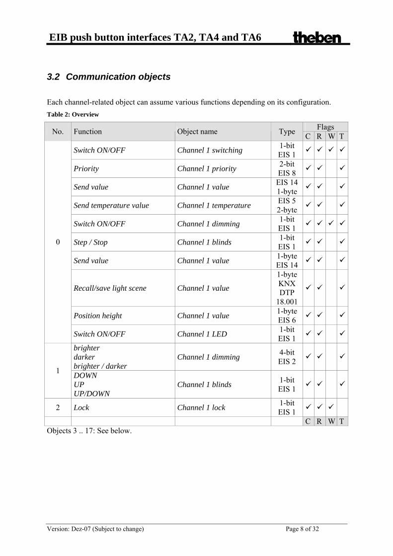
3.2 Communication objects
Each channel-related object can assume various functions depending on its configuration. Table 2: Overview
Flags No. Function Object name Type C R W T
Switch ON/OFF Channel 1 switching 1-bit EIS 1
Priority Channel 1 priority 2-bit EIS 8
Send value Channel 1 value EIS 14 1-byte
Send temperature value Channel 1 temperature EIS 5 2-byte
Switch ON/OFF Channel 1 dimming 1-bit EIS 1
Step / Stop Channel 1 blinds 1-bit EIS 1
Send value Channel 1 value 1-byte EIS 14
Recall/save light scene Channel 1 value
1-byte KNX DTP
18.001
Position height Channel 1 value 1-byte EIS 6
0
Switch ON/OFF Channel 1 LED 1-bit EIS 1
brighter darker brighter / darker
Channel 1 dimming 4-bit EIS 2
1 DOWN UP UP/DOWN
Channel 1 blinds 1-bit EIS 1
2 Lock Channel 1 lock 1-bit EIS 1
C R W T Objects 3 .. 17: See below.

EIB push button interfaces TA2, TA4 and TA6 theben
Version: Dez-07 (Subject to change) Page 9 of 32
Table 3: Overview of object numbers
TA 6 TA 4 -
TA 2 - - Device
Function C1 C2 C3 C4 C5 C6
According to the function of the channel - Switch ON/OFF - Priority - Send value - Send temperature - Step / Stop - Light scene - Position height
0 3 6 9 12 15
According to the function of the channel: - brighter / darker - UP - DOWN - UP/DOWN
1 4 7 10 13 16
Channel X lock 2 5 8 11 14 17

EIB push button interfaces TA2, TA4 and TA6 theben
Version: Dez-07 (Subject to change) Page 10 of 32
3.2.1 Description of objects Objects 0, 3, 6, 9, 12, 15 "Switch ON/OFF, priority, send value, send temperature value, step / stop, recall/save light scene, position height, LED switch" The function and the type of object are dependent on the Function of the input and Object type parameters. Table 4
Function of input Function Description Switch ON/OFF sends 1-bit switching commands in EIS 1
format Priority sends priority telegrams in 2-bit format Send value sends a value between 0 and 255
Switch/ push button
Send temperature value sends a temperature value in 2-byte format Dimming Switch ON/OFF switches dimmer on and off Blinds Step / Stop sends 1-bit "UP" or "DOWN" telegrams.
Value short/long sends 2 different 8-bit values depending on how long the button is pressed
Value for light scene Recall / save light scene via 8-bit telegram
Value
Value for blinds Sends an 8-bit percentage value for positioning blinds
Command LED receives 1-bit telegram to control an LED • Objects 1, 4, 7, 10, 13, 16
"brighter, darker, brighter / darker, UP, DOWN, UP/DOWN, position slats"
The function and the type of the object likewise depend on the „Function of the input“ parameter. Table 5
Set Function of the input
Object function Description
Switch/ push button not available Dimming brighter, darker
brighter / darker 4-bit dimming commands for the dimming actuator in EIS 4 format
Blinds UP, DOWN, UP/DOWN
1-bit motion commands for the blinds actuator in EIS 7 format
Value for blinds Position of slats Sends 1-byte telegram to position slats Command LED not available

EIB push button interfaces TA2, TA4 and TA6 theben
Version: Dez-07 (Subject to change) Page 11 of 32
• Objects 2, 5, 8, 11, 14, 17 "lock"
The corresponding input is disabled via this object. The resulting response can be set individually on the parameter pages. 1 = disabled 0 = cancel lock

EIB push button interfaces TA2, TA4 and TA6 theben
Version: Dez-07 (Subject to change) Page 12 of 32
3.3 Parameters
3.3.1 Parameter pages
Table 6
Function Description Channel 1 .. Channel 6 Parameter for the relevant input Each channel has a parameter page. All pages (and channels) have an identical layout. The first and most important parameter is, on the one hand, "input function" as that sets the channel function. Possible functions include:
• Switch/ push button • Dimmer • Blinds • Value • Command LED
Depending on the function selected, the parameters listed below may change.

EIB push button interfaces TA2, TA4 and TA6 theben
Version: Dez-07 (Subject to change) Page 13 of 32
3.3.2 Parameter description
3.3.2.1 The "switch / push button" function An input is connected to a push button or a switch. When this is pressed, a switching, value, priority or temperature value telegram is sent to the bus. The following parameters are available: Table 7
Designation Values Description Debouncing time 30 ms
50 ms80 ms
100 ms200 ms
1 sec. 5 sec.
10 sec.
The new status of the input is only accepted after a time delay to avoid a disruptive switching process due to debouncing of the contact connected to the input. Larger values (≥ 1s.) can be used as a switch-on delay
Channel sends: Switching (1-bit) Switching telegrams
Priority (2-bit) Priority telegrams Value 0.. 255 (1-byte) Any desired value between 0 and 255
Object type
Temperature value (2-byte) A temperature value in EIS5 format

EIB push button interfaces TA2, TA4 and TA6 theben
Version: Dez-07 (Subject to change) Page 14 of 32
Continuation:
Designation Values Description For object type Switching:
How does the channel respond when input voltage is applied?
None Ignore On Send ON telegram Off Send OFF telegram
Toggle Reverse channel status (cf. notching relay)
For object type Priority 2-bit None No response.
Table 8: Telegrams
Function Value Priority inactive (00) Priority inactive
(no control) 0 (00bin)
Priority ON (11) Priority ON (control: enable, on) 3 (11bin)
Priority OFF (10) Priority OFF (control: disable, off) 2 (10bin)
For object type Value Any value between 0 and 255 can be sent. These values can also be used as Percentage values or as HVAC commands (in German HKL = Heizung/Klima/Lüftung) .
none No response 0 = 0 % (corresponds to HVAC
mode: Auto)0.0% or HVAC “auto” operating mode
1 (corresponds to HVAC mode: Comfort)
1 or HVAC “comfort” operating mode
2 (corresponds to HVAC mode: Standby)
2 or HVAC “standby” operating mode
3 (corresponds to HVAC mode: Night-time temperature
reduction)
3 or HVAC “night temperature reduction” operating mode
4 (corresponds to HVAC mode: Frost protection)
4 or HVAC “frost protection” operating mode
Reaction to rising edge
5 .. 255 any desired value or percentage value Percentage values are given in 5 % increments, e.g. 13 = 5 %, 26 = 10 %, 255 = 100 %.
Reaction to falling edge See Reaction to rising edge How should the channel react after the input is switched off i.e. with a signal change from 1 to 0? See Reaction to rising edge.

EIB push button interfaces TA2, TA4 and TA6 theben
Version: Dez-07 (Subject to change) Page 15 of 32
Continuation:
Designation Values Description For Temperature valueobject type.
Do not send temperature value. No reaction. Temperature value with a rising edge 0°C .. 40°C in 1°C increments Send temperature value.
This function can be used to send a set point value to a thermostat.
Temperature value with a falling edge
See temperature value with a rising edge
Which temperature values should be sent when the input signal changes from 1 to 0?
Common parameters Send telegram cyclically No
Yes Only after rising edge Only after falling edge
Which events should be sent cyclically?
Cycle time 2 minutes, 3 minutes, 5 minutes, 10 minutes, 15 minutes, 20 minutes 30 minutes, 45 minutes, 60 minutes
At what intervals are the telegrams to be resent?
Ignore lock Disable telegrams are ignored No reaction when setting the lock If necessary, only respond if the lock is
cancelled same as after rising edge Send the same telegram as the one
configured for reaction to rising edge.
Reaction when setting the lock
same as after falling edge Send the same telegram as the one configured for reaction to falling edge.
No reaction when canceling the lock
If necessary, only respond if the lock is set
update The current status of the channel is sent.
same as after rising edge Send the same telegram as the one configured for reaction to rising edge.
Reaction when cancelling the lock
same as after falling edge Send the same telegram as the one configured for reaction to falling edge.

EIB push button interfaces TA2, TA4 and TA6 theben
Version: Dez-07 (Subject to change) Page 16 of 32
Continuation:
Designation Values Description none No reaction.
update The current status of the channel is sent.
same as after rising edge Reaction configured as for rising edge.
same as after falling edge Reaction configured as for falling edge.
update after 5 sec.
update after 10 sec.update after 15 sec.
The current channel status is sent after the selected time has elapsed.
after 5 sec. same as after rising edge
after 10 sec. same as after rising edge
after 15 sec. same as after rising edge
After the selected time has elapsed, the channel reacts as if configured for rising edge.
Reaction after restoration of the bus supply
after 5 sec. same as after falling edge
after 10 sec. same as after falling edge
after 15 sec. same as after falling edge
After the selected time has elapsed, the channel reacts as if configured for falling edge.

EIB push button interfaces TA2, TA4 and TA6 theben
Version: Dez-07 (Subject to change) Page 17 of 32
3.3.2.2 The “Dimming” function With the single button operation, an input is connected to a simple push button. With other types of operation 2 inputs and two push buttons are required per dimmer channel. That means that both inputs must be connected via common group addresses. Example: Group address 3/4/5 for brighter object from channel 1 and darker object from channel 2. Group address 3/4/6 for the switch ON/OFF objects from channel 1 and channel 2. Depending on the duration of the keystroke (short/ long key stroke), dimming or ON/OFF telegrams are sent to the dimmer. See below. The following parameters are available: Table 9
Designation Values Description Debouncing time 30 ms
50 ms80 ms
100 ms200 ms
1 sec. 5 sec.
10 sec.
Debouncing of the connected key (see "Switch / push button function" above)
This input distinguishes between a long and a short keystroke, and can therefore perform two functions
Single button operation The dimmer is operated by a single push button. Short keystroke = ON/OFF Long keystroke = brighter / darker� Release = stop With the other models, the dimmer is operated using two keys (rocker).
brighter / ON Short keystroke = ON Long keystroke = brighter Release = stop
brighter / TOGGLE Short keystroke = ON/OFF Long keystroke = brighter Release = stop
darker / OFF Short keystroke = OFF Long keystroke = darker Release = stop
Reaction to “long” / “short”
darker / TOGGLE Short keystroke = ON/OFF Long keystroke = darker Release = stop

EIB push button interfaces TA2, TA4 and TA6 theben
Version: Dez-07 (Subject to change) Page 18 of 32
Continuation:
Designation Values Description Long keystroke starting at
300 .. 1000ms This function serves to clearly differentiate between long and short keystrokes. If the key is pressed at least as long as the set time, then a long keystroke will be registered. With a long keystroke, the dimming value is:
100 % Increased (or decreased) until the key is released.
Increments for dimmer
50 %25 %
12,5 %6 %3 %
1,5 %
Raised by the selected value (or lowered)
Ignore lock Disable telegrams are ignored No response when the lock is set It only reacts once the lock is cancelled
ON Send switch-on telegram
Reaction when setting the lock
OFF Send switch-off telegram No response when the lock is
cancelled Cancelling the lock does not issue a telegram
ON Switch dimmer on
Reaction to cancellation of the lock
OFF Switch dimmer off none No reaction
ON Send switch-on telegram OFF Send switch-off telegram
ON after 5 secON after 10 secON after 15 sec
Send switch-on telegram with delay
Reaction after restoration of the bus supply
OFF after 5 secOFF after 10 secOFF after 15 sec
Send switch-off telegram with delay

EIB push button interfaces TA2, TA4 and TA6 theben
Version: Dez-07 (Subject to change) Page 19 of 32
3.3.2.3 The “Blinds” function With the single button operation, an input is connected to a simple push button. With other types of operation, 2 inputs and two push buttons are required per blinds channel. That means that both inputs must be connected via common group addresses. Example: Group address 3/5/5 for UP object from channel 1 and DOWN object from channel 2. Group address 3/5/6 for the Step /Stop object from channel 1 and channel 2. Motion or step commands are sent to the blinds actuator depending on the duration of the keystroke (short/ long key stroke). See below. The following parameters are available: Table 10
Designation Values Description Debouncing time 30 ms, 50 ms, 80 ms, 100 ms
200 ms, 1 sec. , 5 sec., 10 sec.Debouncing of the connected key (see "Switch / push button function" above)
Single button operation
The blinds are operated with a single push button. Short keystroke = Step Long keystroke = Move
DOWN Short keystroke = Step Long keystroke = Lower
UP Short keystroke = Step Long keystroke = Raise
Operation
Run commands: Direction change with every keystroke. The stop command is triggered either by releasing the button or pressing it briefly, depending on the configuration. See below: Motion is stopped by
Long keystroke starting at
300 .. 1000ms This function serves to clearly differentiate between long and short keystrokes. If the key is pressed at least as long as the set time, then a long keystroke will be registered.
Motion is stopped by releasing the keyShort keystroke
How is the stop command triggered?
Ignore lock Disable telegrams are ignored No reaction when the lock is set only react if the lock is cancelled
UP Send move up command
Reaction when setting the lock
DOWN Send move down command

EIB push button interfaces TA2, TA4 and TA6 theben
Version: Dez-07 (Subject to change) Page 20 of 32
Continuation:
Designation Values Description No reaction when the lock is
cancelledonly react if the lock is set
Up Send move up command
Reaction when cancelling the lock
Down Send move down command none No reaction
UP Send move up command DOWN Send move down command
UP after 5 secUP after 10 secUP after 15 sec
Send delayed move up command
Reaction after restoration of the bus supply
DOWN after 5 secDOWN after 10 secDOWN after 15 sec
Send delayed move down command

EIB push button interfaces TA2, TA4 and TA6 theben
Version: Dez-07 (Subject to change) Page 21 of 32
3.3.2.4 The “Value” function Basic functionality: Pressing the connected push button triggers a value telegram. Two different telegrams can also be sent (“long/short” function) depending on the configuration. Table 11
Designation Values Description Debouncing time 30 ms, 50 ms, 80 ms
100 ms, 200 ms, 1 sec. 5 sec., 10 sec.
Debouncing of the connected key (see above: "The swittch /push button function")
Value short/long Sends two different values, depending on whether the key is pressed for a long or short period
Value for light scene Send a scene number between 0 and 63.
Type of value
Value for blinds Sends a height telegram and a slats telegram
Parameter for the type of value “short / long” Value Input 0 .. 255 Value which is to be sent with a short*
keystroke. Special function after long keystroke
no Yes
Is a different value sent by a long keystroke?
Long keystroke starting at 1 sec.
2 sec. 3 sec. 5 sec.
This function serves to clearly differentiate between long and short keystrokes. If the key is pressed at least as long as the set time, then a long keystroke will be registered.
Value with a long keystroke Input 0 .. 255 Value to be sent with a long keystroke
Designation Values Description Parameter for the type of value “Value for light scene”
Scene number Scene 1 .. ..
Scene 64
Sends the selected scene number (call scene)
Save with long time operation
No yes
If a saved scene telegram is to be sent with a long keystroke
Long keystroke starting at
1 sec. 2 sec. 3 sec. 5 sec.
This function serves to clearly differentiate between long and short
keystrokes. If the key is pressed at least as long as the set time, then a long keystroke will
be registered.

EIB push button interfaces TA2, TA4 and TA6 theben
Version: Dez-07 (Subject to change) Page 22 of 32
Continuation:
Designation Values Description Parameter for the type of value “Value for blinds”
Height 0 .. 100 % in 5 % increments Sends a positioning telegram to the blinds / shutter actuator
Slats 0 .. 100 % in 5 % increments What slat position should be sent to the actuator together with the positioning
telegram?
What function is carried out with a long keystroke?
no none all the way UP (0%) Raise slats to 0% and blinds to upper
stop
Special function after long time operation
all the way DOWN (100%) Lower slats to 100% and blinds to lower stop
Common parameters Ignore lock Disable telegrams are ignored Reaction when setting
the lock lock After a lock telegram (status =1) is received, the channel no longer transmits.
No reaction when the lock is cancelled
No reaction when the lock is cancelled. Reaction when cancelling the lock
update When the lock is cancelled (status=0), the current channel status should be resent.
None No reaction after restoration of the bus supply.
as with short keystroke, send immediately
Same telegram configured as with short keystroke. Send without delay.
Reaction after restoration of the bus supply
as with short keystroke after 5 sec
as with short keystroke after 10 sec
as with short keystroke after 15 sec
Same telegram configured as with short keystroke. Only send after selected delay.
*If the Special function after long keystroke parameter is set to “no”, then the length of the keystroke is irrelevant.
EIB push button interfaces TA2, TA4 and TA6 theben
Version: Dez-07 (Subject to change) Page 23 of 32
4 Appendix
4.1 Typical applications
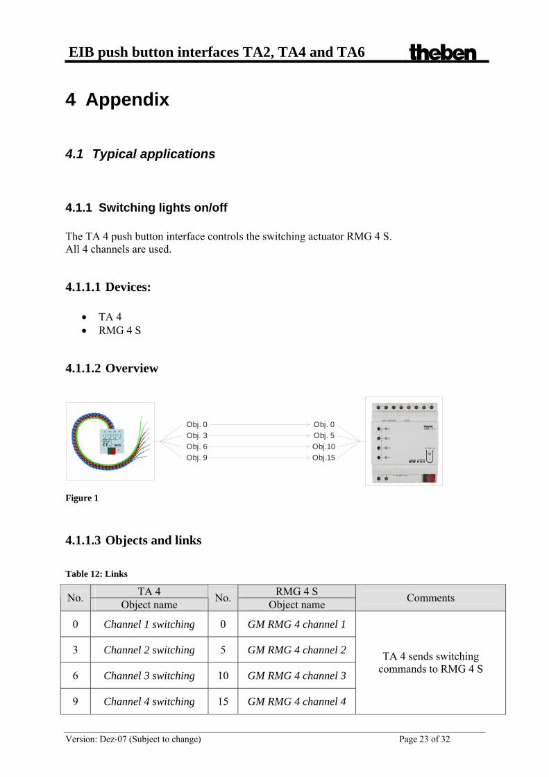
4.1.1 Switching lights on/off The TA 4 push button interface controls the switching actuator RMG 4 S. All 4 channels are used.
4.1.1.1 Devices:
• TA 4 • RMG 4 S
4.1.1.2 Overview
Obj. 0Obj. 3Obj. 6Obj. 9
Obj. 0Obj. 5Obj.10Obj.15
Figure 1
4.1.1.3 Objects and links Table 12: Links
TA 4 RMG 4 S No. Object name No. Object name Comments
0 Channel 1 switching 0 GM RMG 4 channel 1
3 Channel 2 switching 5 GM RMG 4 channel 2
6 Channel 3 switching 10 GM RMG 4 channel 3
9 Channel 4 switching 15 GM RMG 4 channel 4
TA 4 sends switching commands to RMG 4 S

EIB push button interfaces TA2, TA4 and TA6 theben
Version: Dez-07 (Subject to change) Page 24 of 32
4.1.1.4 Important parameter settings The standard parameter settings apply for unlisted parameters. Table 13: TA 6
Parameter page Parameters Setting Channel 1 .. Channel 4 Function of the input Switch/ push button Table 14: RMG 4 S
Parameter page Parameters Setting RMG 4 channel 1… 4 Function Switching On/Off

EIB push button interfaces TA2, TA4 and TA6 theben
Version: Dez-07 (Subject to change) Page 25 of 32
4.1.2 2 Dimmer lighting groups The TA 2 push button interface controls the dimming actuator DMG 2. A push button is connected to each input.
4.1.2.1 Devices:
• TA 2 • DMG 2
4.1.2.2 Overview
Obj. 0Obj. 1Obj. 3Obj. 4
Obj. 0Obj. 1Obj.10Obj.11
Figure 2
4.1.2.3 Objects and links Table 15: Links
TA 2 DMG 2 No. Object name No. Object name Comments
0 Channel 1 Switching On/Off 0 GM DMG 2 channel 1
Switching On/Off
1 Channel 1 dimming brighter / darker 1 GM DMG 2 channel 1
brighter / darker
3 Channel 2 Switching On/Off 10 GM DMG 2 channel 2
Switching On/Off
4 Channel 2 dimming brighter / darker 11 GM DMG 2 channel 2
brighter / darker
Long keystroke for brighter / darker dimmer
commands.
Short keystroke for On/Off commands.
EIB push button interfaces TA2, TA4 and TA6 theben
Version: Dez-07 (Subject to change) Page 26 of 32
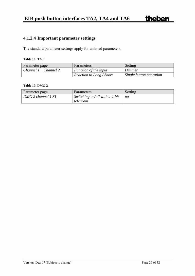
4.1.2.4 Important parameter settings The standard parameter settings apply for unlisted parameters. Table 16: TA 6
Parameter page Parameters Setting Function of the input Dimmer Channel 1 .. Channel 2 Reaction to Long / Short Single button operation
Table 17: DMG 2
Parameter page Parameters Setting DMG 2 channel 1 S1 Switching on/off with a 4-bit
telegram no

EIB push button interfaces TA2, TA4 and TA6 theben
Version: Dez-07 (Subject to change) Page 27 of 32
4.1.3 Control 4 blinds or blinds groups The push button interface TA 2 controls the blinds actuator JMG 4 S. A push button is connected to each input.
4.1.3.1 Devices:
• TA 4 • JMG 4 S
4.1.3.2 Overview
Obj. 0
Obj. 6
Obj. 1
Obj. 7
Obj. 3
Obj. 9
Obj. 4
Obj.10
Obj. 1
Obj.11
Obj. 0
Obj.10
Obj. 6
Obj.16
Obj. 5
Obj.15 Figure 3
4.1.3.3 Objects and links Table 18: Links
TA 4 JMG 4 S No. Object name No. Object name Comments
0 Channel 1 blinds Step / Stop 1 GM JMG 4 S C1
Step / Stop
1 Channel 1 blinds Up / Down 0 GM JMG 4 S C1
Up / Down
3 Channel 2 blinds Step / Stop 6 GM JMG 4 S C2
Step / Stop
4 Channel 2 blinds Up / Down 5 GM JMG 4 S C2
Up / Down
6 Channel 3 blinds Step / Stop 11 GM JMG 4 S C3
Step / Stop
7 Channel 3 blinds Up / Down 10 GM JMG 4 S C3
Up / Down
9 Channel 4 blinds Step / Stop 16 GM JMG 4 S C4
Step / Stop
10 Channel 4 blinds Up / Down 15 GM JMG 4 S C4
Up / Down
Long keystroke for Up / down run commands.
Short keystroke for
Step / Stop commands
EIB push button interfaces TA2, TA4 and TA6 theben
Version: Dez-07 (Subject to change) Page 28 of 32
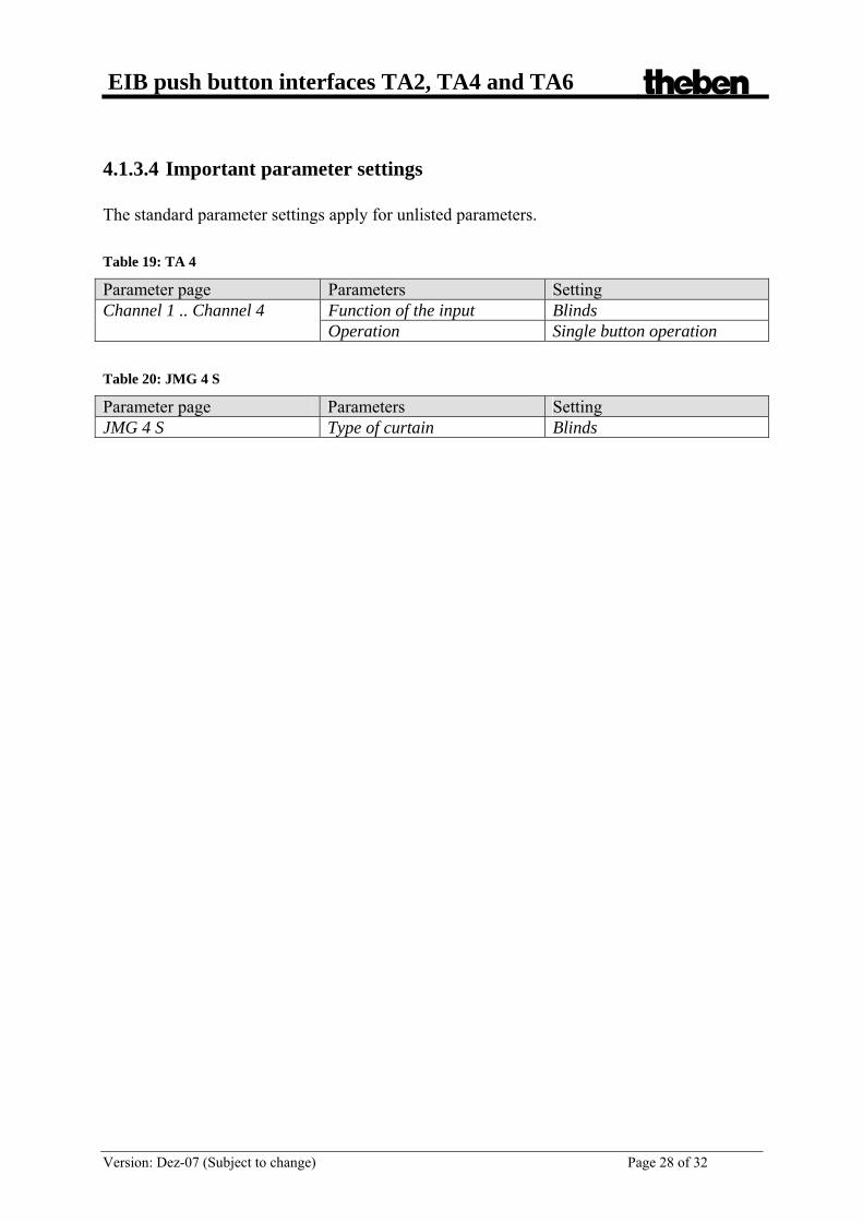
4.1.3.4 Important parameter settings The standard parameter settings apply for unlisted parameters. Table 19: TA 4
Parameter page Parameters Setting Function of the input Blinds Channel 1 .. Channel 4 Operation Single button operation
Table 20: JMG 4 S
Parameter page Parameters Setting JMG 4 S Type of curtain Blinds
EIB push button interfaces TA2, TA4 and TA6 theben
Version: Dez-07 (Subject to change) Page 29 of 32
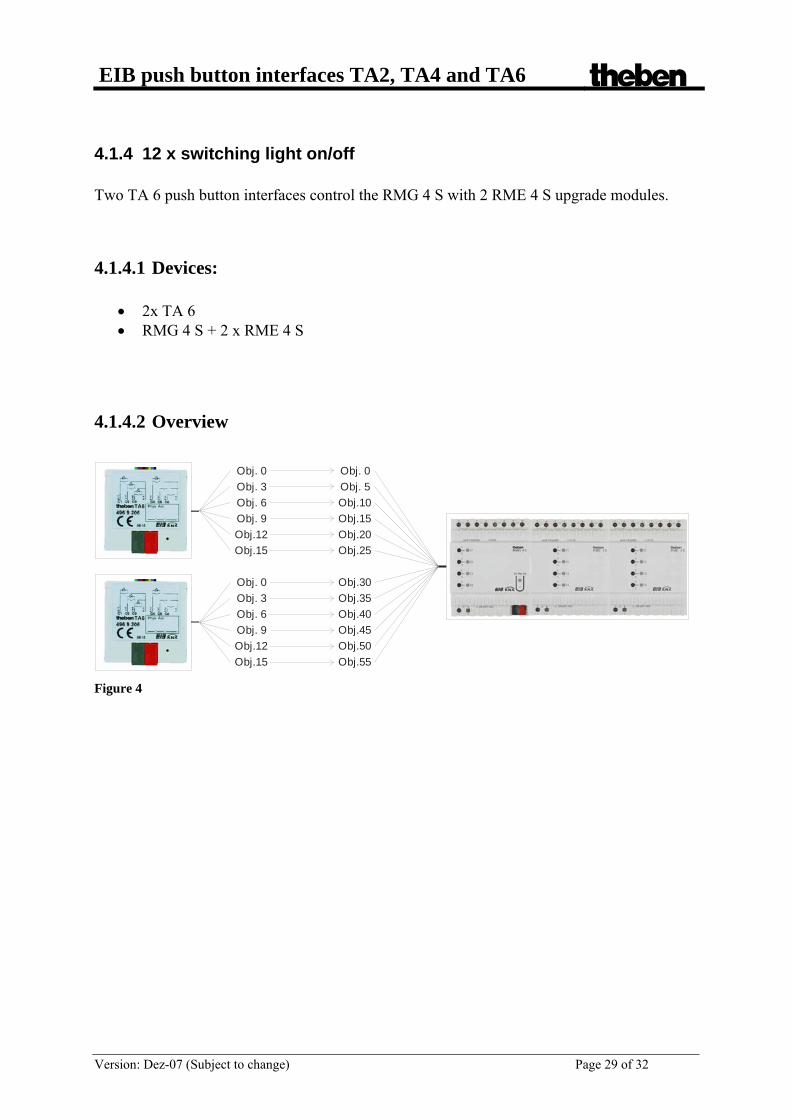
4.1.4 12 x switching light on/off Two TA 6 push button interfaces control the RMG 4 S with 2 RME 4 S upgrade modules.
4.1.4.1 Devices:
• 2x TA 6 • RMG 4 S + 2 x RME 4 S
4.1.4.2 Overview
Obj.15
Obj. 0
Obj.20
Obj. 5
Obj.25
Obj.10Obj. 9
Obj. 0
Obj.12
Obj. 3
Obj.15
Obj. 6
Obj.45
Obj.30
Obj.50
Obj.35
Obj.55
Obj.40Obj. 9
Obj. 0
Obj.12
Obj. 3
Obj.15
Obj. 6
Figure 4

EIB push button interfaces TA2, TA4 and TA6 theben
Version: Dez-07 (Subject to change) Page 30 of 32
4.1.4.3 Objects and links Table 21: Links
1st TA 6 RMG 4 S No. Object name No. Object name Comments
0 Channel 1 switching 0 RMG 4 channel 1
3 Channel 2 switching 5 RMG 4 channel 2
6 Channel 3 switching 10 RMG 4 channel 3
9 Channel 4 switching 15 RMG 4 channel 4
First push button interface and RMG 4 S (basic module)
12 Channel 5 switching 20 EM1 RME 4 channel 1
15 Channel 6 switching 25 EM1 RME 4 channel 2
First push button interface and first
MiX upgrade module RME 4 S
2nd TA 6 RMG 4 S No. Object name No. Object name Comments
0 Channel 1 switching 30 EM1 RME 4 channel 1
3 Channel 2 switching 35 EM1 RME 4 channel 1
Second push button interface and first
MiX upgrade module RME 4 S
6 Channel 3 switching 40 EM2 RME 4 channel 1
9 Channel 4 switching 45 EM2 RME 4 channel 2
12 Channel 5 switching 50 EM2 RME 4 channel 1
15 Channel 6 switching 55 EM2 RME 4 channel 1
Second push button interface and second
MiX upgrade module RME 4 S

EIB push button interfaces TA2, TA4 and TA6 theben
Version: Dez-07 (Subject to change) Page 31 of 32
4.1.4.4 Important parameter settings The standard parameter settings apply for unlisted parameters. Table 22: TA 6
Parameter page Parameters Setting Channel 1 .. Channel 6 Function of the input Switch/ push button Table 23: RMG 4 S
Parameter page Parameters Setting Number of upgrade modules 2 upgrade modules Type of 1st upgrade module EM1
EM1 is a RME4 S or RME4 C load
General
Type of 2nd upgrade module EM2
EM2 is a RME4 S or RME4 C load
RMG 4 channel 1… 4 Function Switching On/Off EM1 RME 4 channel 1… 4 Function Switching On/Off EM2 RME 4 channel 1… 4 Function Switching On/Off

EIB push button interfaces TA2, TA4 and TA6 theben
Version: Dez-07 (Subject to change) Page 32 of 32
4.2 Conversion of percentages to hexadecimal and decimal values
% Decimal Hexadec
imal % Decimal Hexadec
imal % Decimal Hexadec
imal 0% 0 $00 34% 87 $56 68% 173 $AD 1% 3 $02 35% 89 $59 69% 176 $AF 2% 5 $05 36% 92 $5B 70% 179 $B2 3% 8 $07 37% 94 $5E 71% 181 $B5 4% 10 $0A 38% 97 $60 72% 184 $B7 5% 13 $0C 39% 99 $63 73% 186 $BA 6% 15 $0F 40% 102 $66 74% 189 $BC 7% 18 $11 41% 105 $68 75% 191 $BF 8% 20 $14 42% 107 $6B 76% 194 $C1 9% 23 $16 43% 110 $6D 77% 196 $C4 10% 26 $19 44% 112 $70 78% 199 $C6 11% 28 $1C 45% 115 $72 79% 201 $C9 12% 31 $1E 46% 117 $75 80% 204 $CC 13% 33 $21 47% 120 $77 81% 207 $CE 14% 36 $23 48% 122 $7A 82% 209 $D1 15% 38 $26 49% 125 $7C 83% 212 $D3 16% 41 $28 50% 128 $7F 84% 214 $D6 17% 43 $2B 51% 130 $82 85% 217 $D8 18% 46 $2D 52% 133 $84 86% 219 $DB 19% 48 $30 53% 135 $87 87% 222 $DD 20% 51 $33 54% 138 $89 88% 224 $E0 21% 54 $35 55% 140 $8C 89% 227 $E2 22% 56 $38 56% 143 $8E 90% 230 $E5 23% 59 $3A 57% 145 $91 91% 232 $E8 24% 61 $3D 58% 148 $93 92% 235 $EA 25% 64 $3F 59% 150 $96 93% 237 $ED 26% 66 $42 60% 153 $99 94% 240 $EF 27% 69 $44 61% 156 $9B 95% 242 $F2 28% 71 $47 62% 158 $9E 96% 245 $F4 29% 74 $49 63% 161 $A0 97% 247 $F7 30% 77 $4C 64% 163 $A3 98% 250 $F9 31% 79 $4F 65% 166 $A5 99% 252 $FC 32% 82 $51 66% 168 $A8 100% 255 $FF 33% 84 $54 67% 171 $AA
Top Related