


Languages
Pages
Legal


EE382V: System-on-Chip (SoC) Design Lecture 4
© 2014 A. Gerstlauer 1
EE382V:System-on-a-Chip (SoC) Design
Andreas GerstlauerElectrical and Computer Engineering
University of Texas at [email protected]
Lecture 4 – DRM OverviewSources:
Dr. Saf Asghar, Austin,Prof. Y. Richard Yang, YaleSriram Sambamurthy, UT
Chip Fleming, Spectrum Applications
EE382V: SoC Design, Lecture 4 © 2014 A. Gerstlauer 2
Lecture 4: Outline
• Introduction to OFDM• Wireless transmission
• Modulation
• Coding
• OFDM basics
• DRM Tutorial• Overview
• Channel estimation
• Synchronization
EE382V: System-on-Chip (SoC) Design Lecture 4
© 2014 A. Gerstlauer 2
EE382V: SoC Design, Lecture 4 © 2014 A. Gerstlauer 3
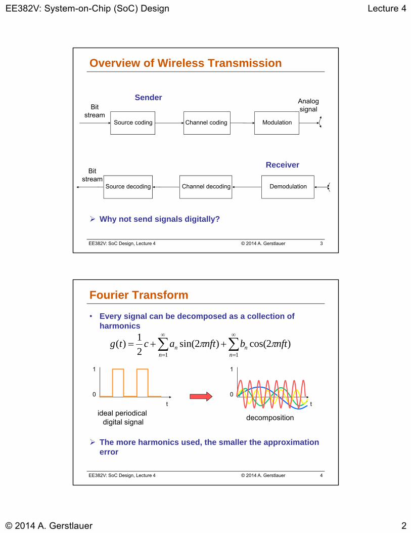
Overview of Wireless Transmission
Why not send signals digitally?
Source coding
Bitstream
Channel coding
Analogsignal
Sender
Modulation
Source decoding
Bitstream
Channel decoding
Receiver
Demodulation
EE382V: SoC Design, Lecture 4 © 2014 A. Gerstlauer 4
)2cos()2sin(2
1)(
11
nftbnftactgn
nn
n
1
0
1
0
t t
ideal periodicaldigital signal
decomposition
Fourier Transform
• Every signal can be decomposed as a collection of harmonics
The more harmonics used, the smaller the approximation error
EE382V: System-on-Chip (SoC) Design Lecture 4
© 2014 A. Gerstlauer 3
EE382V: SoC Design, Lecture 4 © 2014 A. Gerstlauer 5
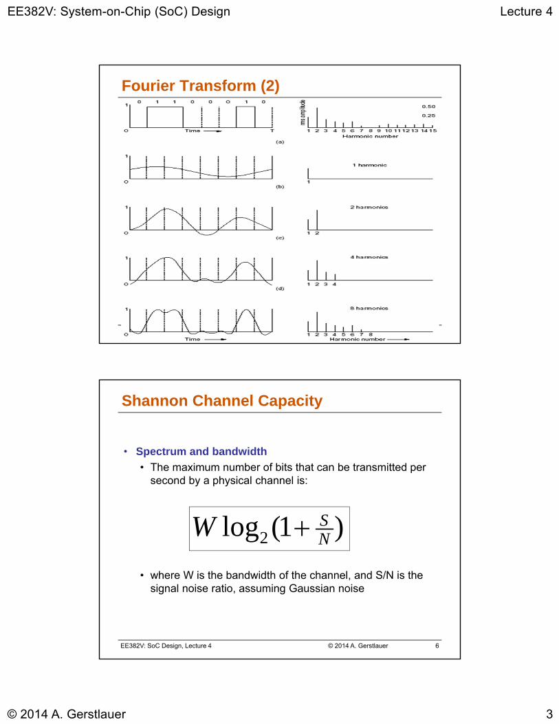
Fourier Transform (2)
EE382V: SoC Design, Lecture 4 © 2014 A. Gerstlauer 6
• Spectrum and bandwidth
• The maximum number of bits that can be transmitted per second by a physical channel is:
• where W is the bandwidth of the channel, and S/N is the signal noise ratio, assuming Gaussian noise
)1(log2 NSW
Shannon Channel Capacity
EE382V: System-on-Chip (SoC) Design Lecture 4
© 2014 A. Gerstlauer 4
EE382V: SoC Design, Lecture 4 © 2014 A. Gerstlauer 7
Frequencies for Communication
VLF = Very Low Frequency UHF = Ultra High Frequency
LF = Low Frequency SHF = Super High Frequency
MF = Medium Frequency EHF = Extra High Frequency
HF = High Frequency UV = Ultraviolet Light
VHF = Very High Frequency
• Frequency and wave length: = c/f
• Wave length , speed of light c 3x10⁸m/s, frequency f
1 Mm300 Hz
10 km30 kHz
100 m3 MHz
1 m300 MHz
10 mm30 GHz
100 m3 THz
1 m300 THz
visible lightVLF LF MF HF VHF UHF SHF EHF infrared UV
optical transmissioncoax cabletwisted pair
EE382V: SoC Design, Lecture 4 © 2014 A. Gerstlauer 8
• ITU-R holds auctions for new frequencies, manages frequency bands worldwide (WRC, World Radio Conferences)
Frequencies and Regulations
Europe USA Japan
CellularPhones
GSM 450 - 457, 479 -486/460 - 467,489 -496, 890 - 915/935 -960,1710 - 1785/1805 -1880UMTS (FDD) 1920 -1980, 2110 - 2190UMTS (TDD) 1900 -1920, 2020 - 2025
AMPS , TDMA , CDMA824 - 849, 869 -894TDMA , CDMA , GSM1850 - 1910,1930 - 1990
PDC810 - 826, 940 - 956,1429 - 1465, 1477 - 1513
CordlessPhones
CT1+ 885 - 887, 930 -932CT2864 - 868DECT 1880 - 1900
PACS 1850 - 1910, 1930 -1990PACS -UB 1910 - 1930
PHS1895 - 1918JCT254 -380
Wireless LANs
IEEE 802.112400 - 2483HIPERLAN 25150 - 5350, 5470 -5725
902 -928I EEE 802.112400 - 24835150 - 5350, 5725 - 5825
IEEE 802.112471 - 24975150 - 5250
Others RF- Control27, 128, 418, 433,
868
RF- Control315, 915
RF- Control426, 868

EE382V: System-on-Chip (SoC) Design Lecture 4
© 2014 A. Gerstlauer 5
EE382V: SoC Design, Lecture 4 © 2014 A. Gerstlauer 9
1 0 1
t
1 0 1
t
1 0 1
t
Digital Modulation
• Amplitude shift keying (ASK)
• Frequency shift keying (FSK)
• Phase shift keying (PSK)
Bandwidth requirements and resistance to interference?
EE382V: SoC Design, Lecture 4 © 2014 A. Gerstlauer 10
• BPSK (Binary Phase Shift Keying)
• Bit value 0: sine wave
• Bit value 1: inverted sine wave
• Very simple PSK
• Properties
• Low spectral efficiency
• Robust, used e.g. in satellite systems
Q
I01
Phase Shift Keying: BPSK
b
Rb =Bb = 1/Tb
b
Spectral density of BPSK
fc : freq. of carrier
fc
EE382V: System-on-Chip (SoC) Design Lecture 4
© 2014 A. Gerstlauer 6
EE382V: SoC Design, Lecture 4 © 2014 A. Gerstlauer 11
Phase Shift Keying: QPSK
Q
I
11
01
10
00
11 10 00 01
A
t
• QPSK (Quadrature Phase Shift Keying)
• 2 bits coded as one symbol
• Symbol determines shift of sine wave
• Often also transmission of relative, not absolute phase shift
– DQPSK - Differential QPSK
• Properties
• Less bandwidth compared to BPSK
EE382V: SoC Design, Lecture 4 © 2014 A. Gerstlauer 12
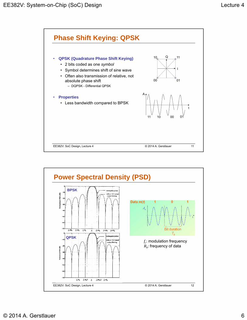
Power Spectral Density (PSD)
BPSK
QPSKfc: modulation frequencyRb: frequency of data
EE382V: System-on-Chip (SoC) Design Lecture 4
© 2014 A. Gerstlauer 7
EE382V: SoC Design, Lecture 4 © 2014 A. Gerstlauer 13
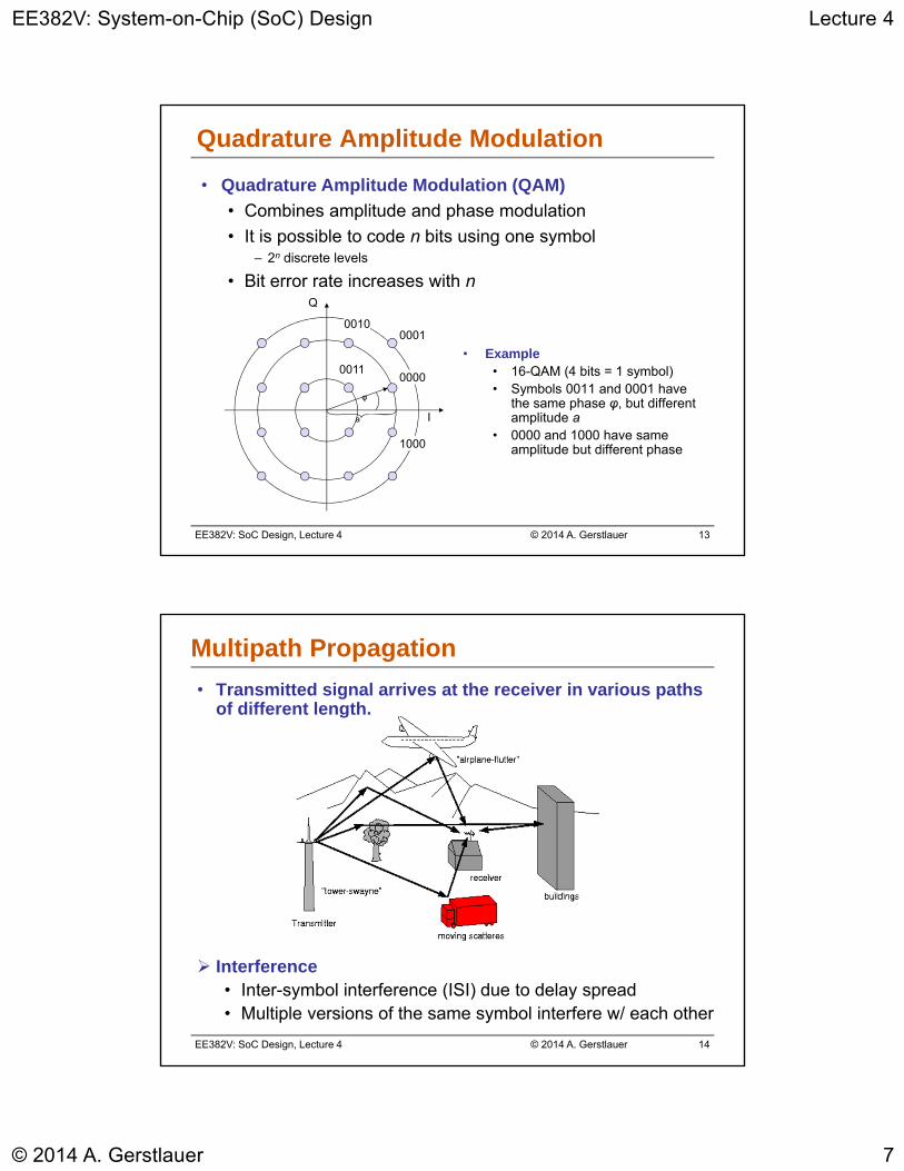
• Quadrature Amplitude Modulation (QAM)
• Combines amplitude and phase modulation
• It is possible to code n bits using one symbol– 2n discrete levels
• Bit error rate increases with n
0000
0001
0011
1000
Q
I
0010
φ
a
Quadrature Amplitude Modulation
• Example• 16-QAM (4 bits = 1 symbol)• Symbols 0011 and 0001 have
the same phase φ, but different amplitude a
• 0000 and 1000 have same amplitude but different phase
EE382V: SoC Design, Lecture 4 © 2014 A. Gerstlauer 14
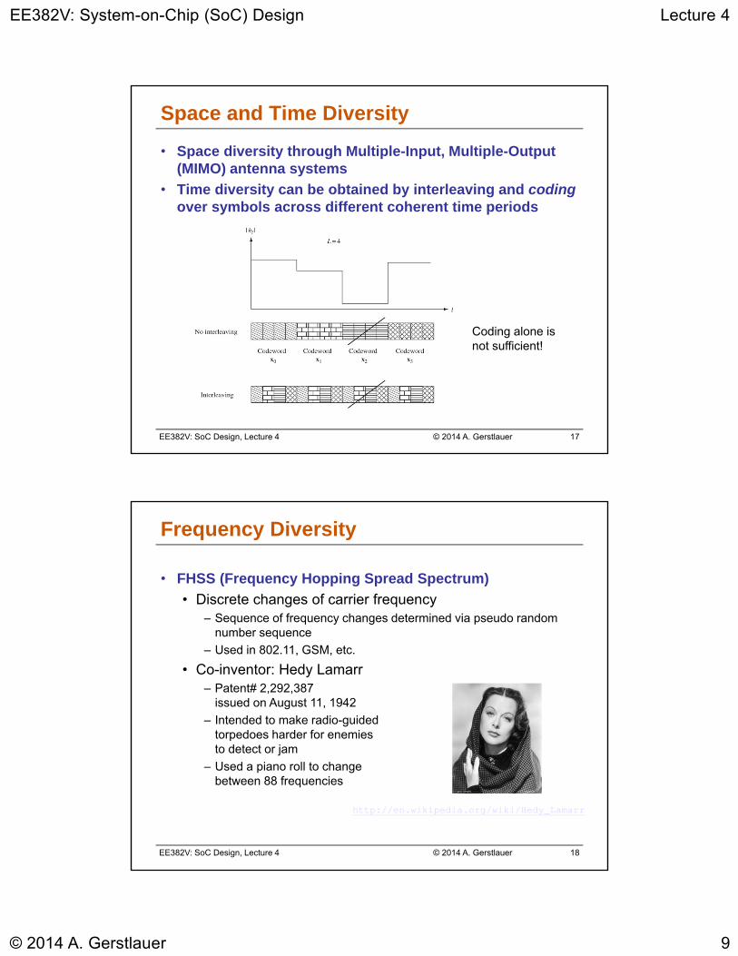
Multipath Propagation
• Transmitted signal arrives at the receiver in various paths of different length.
Interference• Inter-symbol interference (ISI) due to delay spread• Multiple versions of the same symbol interfere w/ each other

EE382V: System-on-Chip (SoC) Design Lecture 4
© 2014 A. Gerstlauer 8
EE382V: SoC Design, Lecture 4 © 2014 A. Gerstlauer 15
Inter Symbol Interference (ISI)
• Delay spread
• Channel delay spread can cause ISI
• Power delay profile conveys the multipath delay spread effects of the channel
• RMS delay spread quantifies the severity of the ISI phenomenon
• The ratio of RMS delay spread to the data symbol period determines the severity of the ISI
• Reduced symbol rate
• Long symbols with guard time at symbol transitions
• Delay spread related to frequency-selectivity of fading
• Flat fading occurs when the symbol period is large compared to the delay spread
EE382V: SoC Design, Lecture 4 © 2014 A. Gerstlauer 16
Interference Channels
• Multipath interference
• Fading due to constructive and destructive addition of multipath signals
• Communication over a flat fading channel has poor performance due to significant probability that channel is in a deep fade
• Reliability is increased by providing more resolvable signal paths that fade independently
• Diversity can be provided across
• Time, space and frequency
• How to exploit the added diversity in an efficient manner?
EE382V: System-on-Chip (SoC) Design Lecture 4
© 2014 A. Gerstlauer 9
EE382V: SoC Design, Lecture 4 © 2014 A. Gerstlauer 17
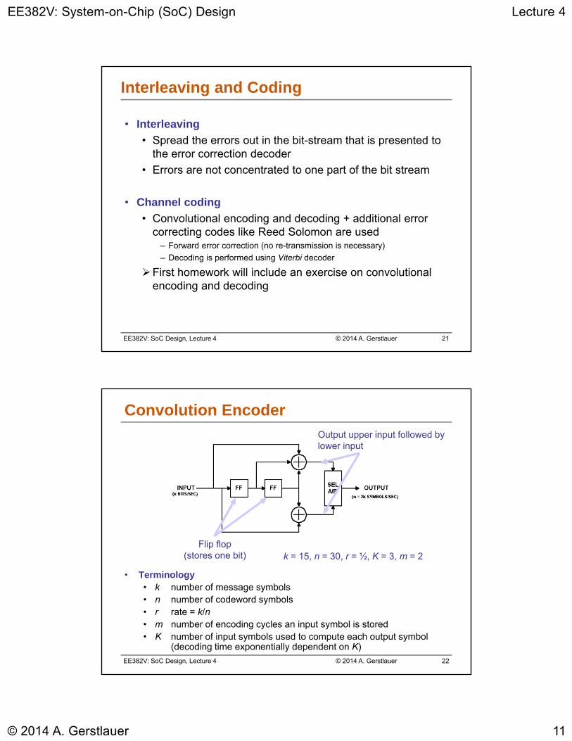
Space and Time Diversity
• Space diversity through Multiple-Input, Multiple-Output (MIMO) antenna systems
• Time diversity can be obtained by interleaving and codingover symbols across different coherent time periods
Coding alone isnot sufficient!
EE382V: SoC Design, Lecture 4 © 2014 A. Gerstlauer 18
• FHSS (Frequency Hopping Spread Spectrum)
• Discrete changes of carrier frequency– Sequence of frequency changes determined via pseudo random
number sequence
– Used in 802.11, GSM, etc.
• Co-inventor: Hedy Lamarr– Patent# 2,292,387
issued on August 11, 1942
– Intended to make radio-guided torpedoes harder for enemies to detect or jam
– Used a piano roll to change between 88 frequencies
Frequency Diversity
http://en.wikipedia.org/wiki/Hedy_Lamarr

EE382V: System-on-Chip (SoC) Design Lecture 4
© 2014 A. Gerstlauer 10
EE382V: SoC Design, Lecture 4 © 2014 A. Gerstlauer 19
Frequency Hopping Spread Spectrum
• Two versions• Slow hopping: several user bits per frequency • Fast hopping: several frequencies per user bit
user data
slowhopping(3 bits/hop)
fasthopping(3 hops/bit)
0 1
tb
0 1 1 t
f
f1
f2
f3
t
td
f
f1
f2
f3
t
td
tb: bit period td: dwell time
EE382V: SoC Design, Lecture 4 © 2014 A. Gerstlauer 20
Lecture 3: Outline
• Introduction to OFDMWireless transmission
Modulation
• Coding
• OFDM basics
• DRM Tutorial• Overview
• Channel estimation
• Synchronization
EE382V: System-on-Chip (SoC) Design Lecture 4
© 2014 A. Gerstlauer 11
EE382V: SoC Design, Lecture 4 © 2014 A. Gerstlauer 21
Interleaving and Coding
• Interleaving
• Spread the errors out in the bit-stream that is presented to the error correction decoder
• Errors are not concentrated to one part of the bit stream
• Channel coding
• Convolutional encoding and decoding + additional error correcting codes like Reed Solomon are used
– Forward error correction (no re-transmission is necessary)
– Decoding is performed using Viterbi decoder
First homework will include an exercise on convolutional encoding and decoding
EE382V: SoC Design, Lecture 4 © 2014 A. Gerstlauer 22
Convolution Encoder
• Terminology• k number of message symbols• n number of codeword symbols • r rate = k/n• m number of encoding cycles an input symbol is stored• K number of input symbols used to compute each output symbol
(decoding time exponentially dependent on K)
Flip flop(stores one bit) k = 15, n = 30, r = ½, K = 3, m = 2
Output upper input followed by lower input

EE382V: System-on-Chip (SoC) Design Lecture 4
© 2014 A. Gerstlauer 12
EE382V: SoC Design, Lecture 4 © 2014 A. Gerstlauer 23
Encoding Example
• Both flip-flops set to 0 initially
• Input: 0 1 0 1 1 1 0 0 1 0 1 0 0 0 1
• Output: 00 11 10 00 01 10 01 11 11 10 00 10 11 00 11
• Flush encoder by clocking m = 2 times with 0 inputs.
EE382V: SoC Design, Lecture 4 © 2014 A. Gerstlauer 24
State Transition and Output Tables
Next State, if
Current State Input = 0: Input = 1:
00 00 10
01 00 10
10 01 11
11 01 11
Output Symbols, if
Current State Input = 0: Input = 1:
00 00 11
01 11 00
10 10 01
11 01 10
State transition table Output table
2K-1 rows, 2k columns

EE382V: System-on-Chip (SoC) Design Lecture 4
© 2014 A. Gerstlauer 13
EE382V: SoC Design, Lecture 4 © 2014 A. Gerstlauer 25
State Transitions
Next State, if
Current State
Input = 0: Input = 1:
00 00 10
01 00 10
10 01 11
11 01 11
Input symbol is 1
Input symbol is 0
Arcs labeled with output symbols
Output Symbols, if
Current State
Input = 0: Input = 1:
00 00 11
01 11 00
10 10 01
11 01 10
EE382V: SoC Design, Lecture 4 © 2014 A. Gerstlauer 26
Trellis

EE382V: System-on-Chip (SoC) Design Lecture 4
© 2014 A. Gerstlauer 14
EE382V: SoC Design, Lecture 4 © 2014 A. Gerstlauer 27
Viterbi Decoding
• Decoding trellis-coded modulation in modems
• Highly parallelizable convolutional decoding algorithm
• Most common forward error correction (FEC) technique used in space communications (r = ½, K = 7)
• Usually implemented as serial concatenated block and convolutional coding – first Reed-Solomon, then convolutional
Turbo codes are a new parallel-concatenated convolutional coding technique
EE382V: SoC Design, Lecture 4 © 2014 A. Gerstlauer 28
Lecture 3: Outline
• Introduction to OFDMWireless transmission
Modulation
Coding
• OFDM basics
• DRM Tutorial• Overview
• Channel estimation
• Synchronization
EE382V: System-on-Chip (SoC) Design Lecture 4
© 2014 A. Gerstlauer 15
EE382V: SoC Design, Lecture 4 © 2014 A. Gerstlauer 29
OFDM
• A solution for multi-path ISI channels
• Convert high-rate stream into several low-rate streams
• Parallel streams are modulated onto orthogonal carriers– Frequency diversity across symbols
– Data symbols modulated on these carriers without mutual interference
– Overlap of the modulated carriers in the frequency domain (unlike FDM)
• Interleaving and coding to address flat fading carriers
Orthogonal Frequency Division Multiplexing (OFDM)
• High bit-rate wireless applications
• Without a high complexity receiver– (De)modulation using efficient (I)FFTs
• OFDM is part of WLAN, DVB, and BWA standards– IEEE 802.11a standard
• 4G wireless standards (LTE)
EE382V: SoC Design, Lecture 4 © 2014 A. Gerstlauer 30
12
0
( ) k
Nj f t
kk
s t X e
t os]
Orthogonality condition:
*1 2
0
( ). ( ) 0T
g t g t dt In our case:
2 2
0
. 0p q
Tj f t j f te e dt
For p q where fk=k/T
OFDM Mathematics

EE382V: System-on-Chip (SoC) Design Lecture 4
© 2014 A. Gerstlauer 16
EE382V: SoC Design, Lecture 4 © 2014 A. Gerstlauer 31
Transmitted Spectrum
EE382V: SoC Design, Lecture 4 © 2014 A. Gerstlauer 32
OFDM Basics
• Terminology
• Orthogonal carriers referred to as subcarriers {fi,i=0,....N-1}
• OFDM symbol period {Tos= N x Ts}
• Subcarrier spacing Df = 1/Tos
• Implementation
• Take N symbols and use one symbol for each subcarrier
• Straightforward implementation can be expensive if we use one oscillator for each subcarrier
• Key observation: consider data as coefficients in the frequency domain, use inverse Fourier transform to generate time-domain sequence

EE382V: System-on-Chip (SoC) Design Lecture 4
© 2014 A. Gerstlauer 17
EE382V: SoC Design, Lecture 4 © 2014 A. Gerstlauer 33
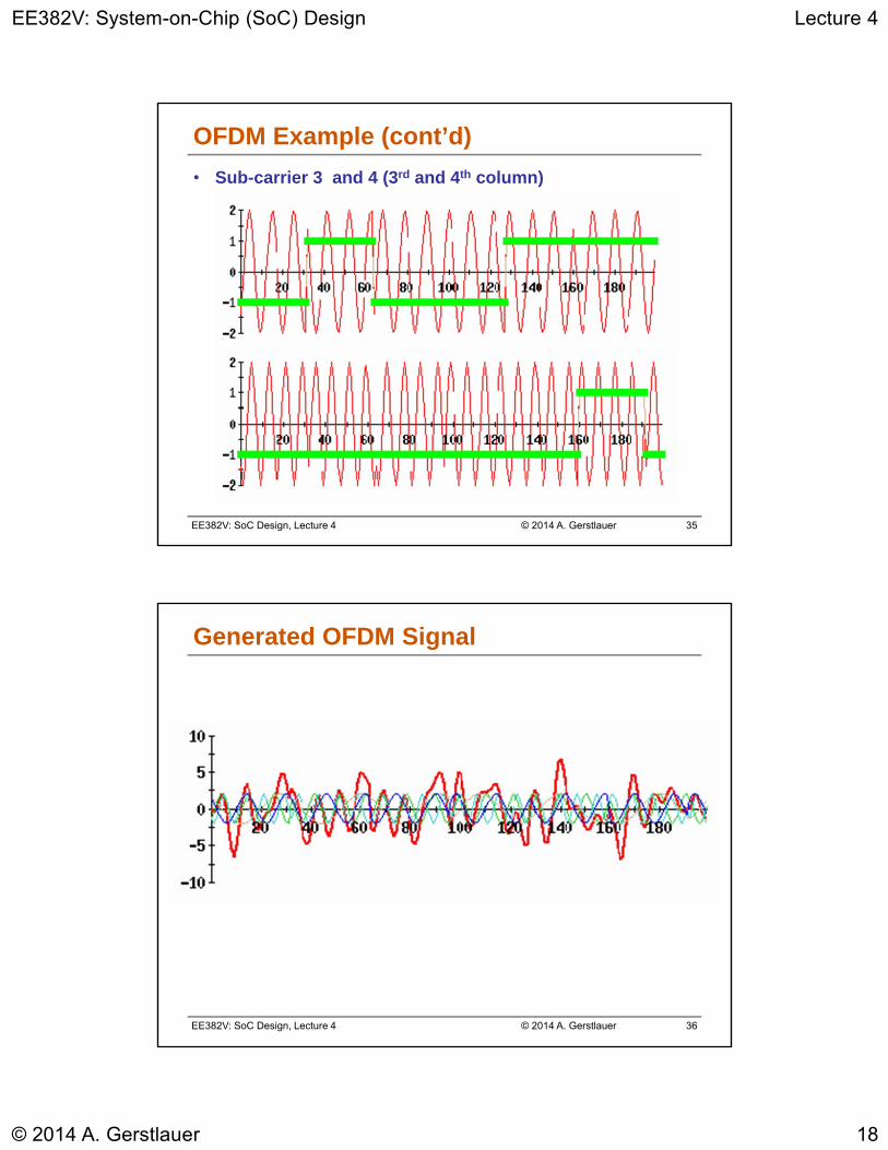
OFDM Example
• 24 bits of data to be transmitted
• 1 1 -1 -1 1 1 1 -1 1 -1 -1 -1 -1 1 -1 -1 -1 1 1 -1 -1 -1 1 1
• 4 subcarriers, each modulated using BPSK
c1 c2 c3 c41 1 -1 -11 1 1 -11 -1 -1 -1-1 1 -1 -1-1 1 1 -1-1 -1 1 1
EE382V: SoC Design, Lecture 4 © 2014 A. Gerstlauer 34
OFDM Example (cont’d)
• Sub-carrier 1 and the bits it is modulating (1st column)
• Sub-carrier 2 and the bits it is modulating (2nd column)
EE382V: System-on-Chip (SoC) Design Lecture 4
© 2014 A. Gerstlauer 18
EE382V: SoC Design, Lecture 4 © 2014 A. Gerstlauer 35
OFDM Example (cont’d)
• Sub-carrier 3 and 4 (3rd and 4th column)
EE382V: SoC Design, Lecture 4 © 2014 A. Gerstlauer 36
Generated OFDM Signal
EE382V: System-on-Chip (SoC) Design Lecture 4
© 2014 A. Gerstlauer 19
EE382V: SoC Design, Lecture 4 © 2014 A. Gerstlauer 37
OFDM and FFT
• Fast Fourier Transform (FFT)
• Samples of the multicarrier signal can be obtained using the inverse FFT (IFFT) of the data symbols - a key issue
• FFT used at the receiver to obtain the data symbols
• No need for ‘N’ oscillators, filters, etc.
• Popularity of OFDM is due to the use of IFFT/FFT which have efficient implementations
• Interpretation of FFT and IFFT
• IFFT at the transmitter & FFT at the receiver
• Data symbols modulate the spectrum and the time domain symbols are obtained using the IFFT
• Time domain symbols are then sent on the channel
• FFT at the receiver to obtain the data
EE382V: SoC Design, Lecture 4 © 2014 A. Gerstlauer 38
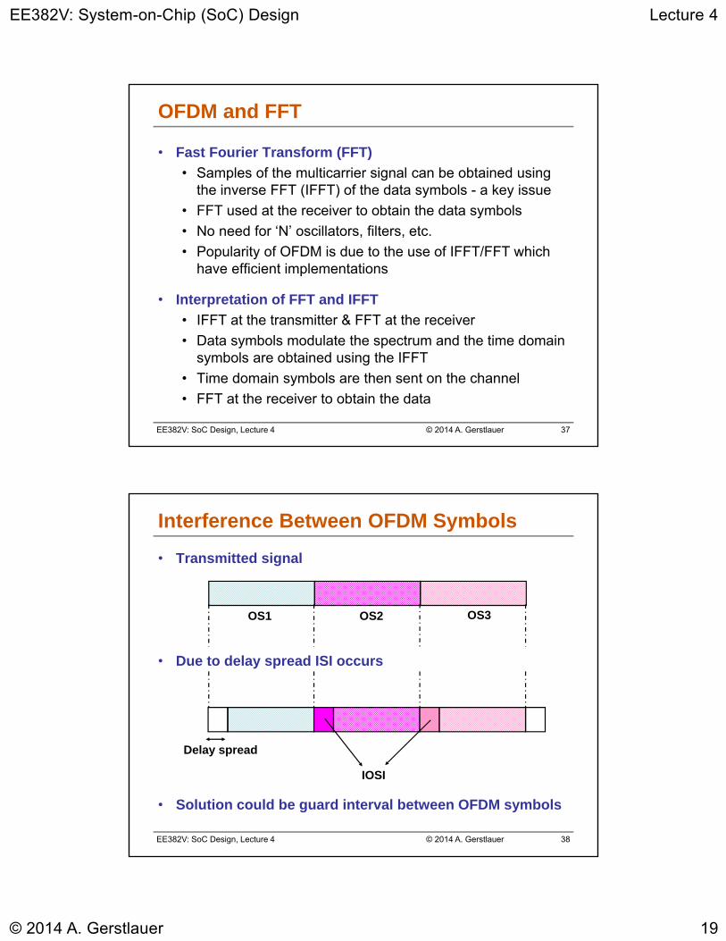
• Transmitted signal
• Due to delay spread ISI occurs
• Solution could be guard interval between OFDM symbols
Delay spread
IOSI
OS1 OS2 OS3
Interference Between OFDM Symbols
EE382V: System-on-Chip (SoC) Design Lecture 4
© 2014 A. Gerstlauer 20
EE382V: SoC Design, Lecture 4 © 2014 A. Gerstlauer 39
Cyclic Prefix
• Inter-OFDM symbol interference (IOSI)
• Zeros used in the guard time can alleviate interference between OFDM symbols
• Orthogonality of carriers is lost when multipath channels are involved
Cyclic prefix can restore the orthogonality
• Convert a linear convolution channel into a circular convolution channel
• This restores the orthogonality at the receiver
• Energy is wasted in the cyclic prefix samples
EE382V: SoC Design, Lecture 4 © 2014 A. Gerstlauer 40
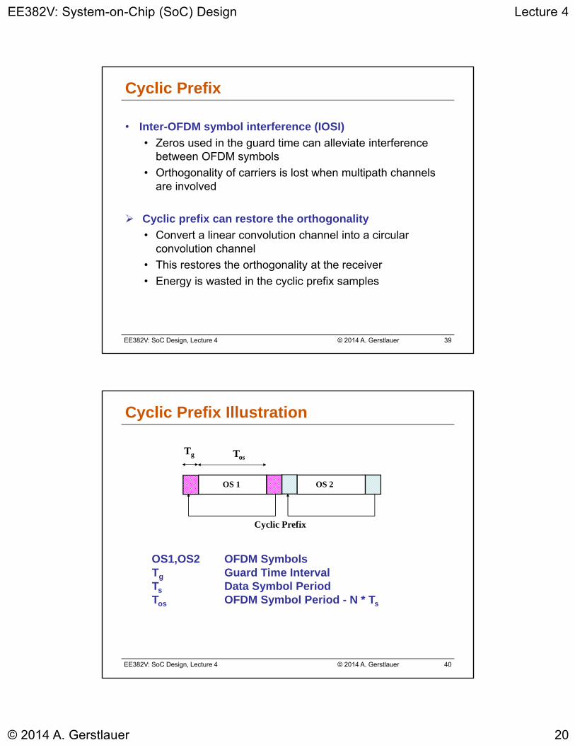
TosTg
Cyclic Prefix
OS 1 OS 2
OS1,OS2 OFDM SymbolsTg Guard Time IntervalTs Data Symbol PeriodTos OFDM Symbol Period - N * Ts
Cyclic Prefix Illustration
EE382V: System-on-Chip (SoC) Design Lecture 4
© 2014 A. Gerstlauer 21
EE382V: SoC Design, Lecture 4 © 2014 A. Gerstlauer 41
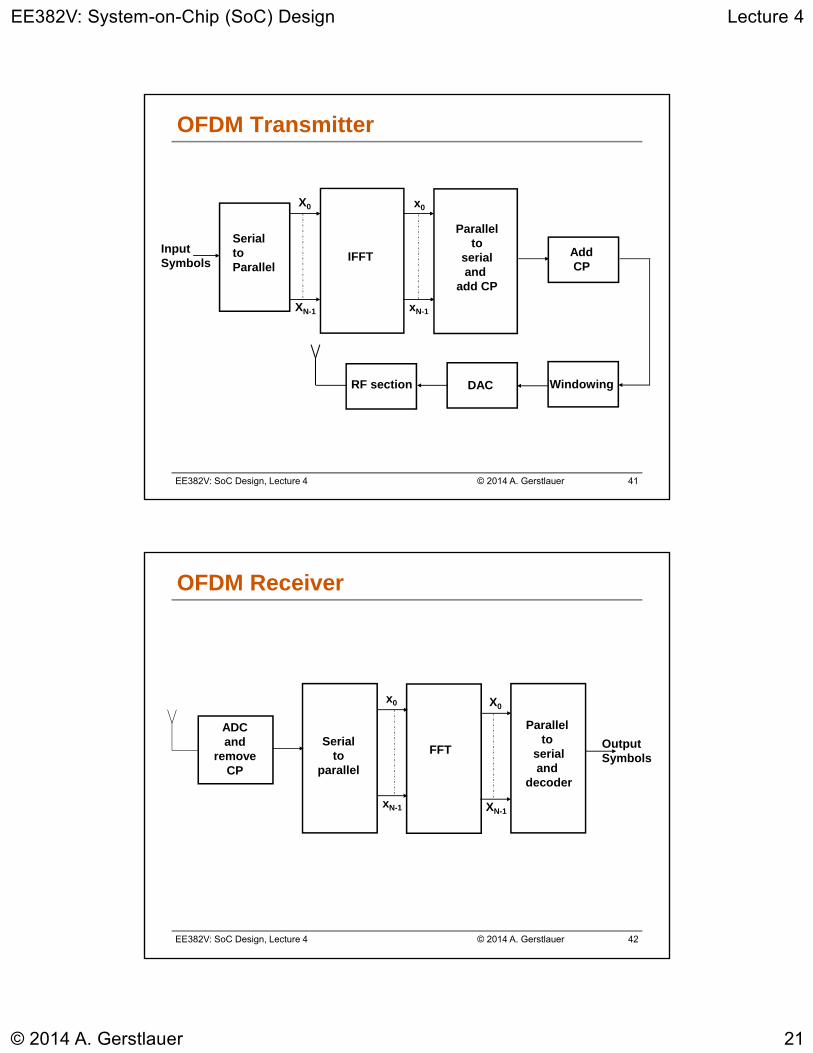
Serialto Parallel
X0
XN-1
x0
xN-1
IFFT
Parallelto
serialand
add CP
Add CP
WindowingDACRF section
InputSymbols
OFDM Transmitter
EE382V: SoC Design, Lecture 4 © 2014 A. Gerstlauer 42
ADCand
removeCP
Serial to
parallel
FFT
Parallel to
serialand
decoder
X0
XN-1
x0
xN-1
OutputSymbols
OFDM Receiver

EE382V: System-on-Chip (SoC) Design Lecture 4
© 2014 A. Gerstlauer 22
EE382V: SoC Design, Lecture 4 © 2014 A. Gerstlauer 43
Synchronization
• Timing and frequency offset can influence performance
• Inter-symbol interference (ISI)
• Inter-carrier interference (ICI)
• Timing influences demodulation window
• Shift of demodulation window leads to ISI
• Frequency influences orthogonality of subcarriers
• Loss of orthogonality leads to ICI
Timing and frequency synchronization
• Acquisition followed by tracking
EE382V: SoC Design, Lecture 4 © 2014 A. Gerstlauer 44
References and Sources
• http://www.ert.rwth-aachen.de/Projekte/Theo/OFDM/www_ofdm.html
• http://www.wave-report.com/tutorials/OFDM.htm
• http://www.radio-electronics.com/info/rf-technology-design/ofdm/ofdm-basics-tutorial.php
• http://eesof.tm.agilent.com/docs/adsdoc2005A/dgwlan/dgwlan013.html
• http://bwrc.eecs.berkeley.edu/Classes/EE225C/Lectures/Lec16_ofdm.pdf
• http://cnx.org/content/m11762/latest/
• http://drm.sourceforge.net/
• http://www.intel.com/technology/itj/2003/volume07issue03/art05_air/vol7iss3_art05.pdf
• http://ieeexplore.ieee.org/Xplore/login.jsp?url=/iel5/35/27889/01244928.pdf
• http://www.ece.rochester.edu/research/wcng/papers/theses/goldsmith_MSthesis.pdf
• http://developer.intel.com/technology/itj/2004/volume08issue03/art03_scalableofdma/vol8_art03.pdf
• http://www.complextoreal.com/chapters/ofdm2.pdf

EE382V: System-on-Chip (SoC) Design Lecture 4
© 2014 A. Gerstlauer 23
EE382V: SoC Design, Lecture 4 © 2014 A. Gerstlauer 45
Lecture 3: Outline
Introduction to OFDMWireless transmission
Modulation
Coding
OFDM basics
• DRM Tutorial• Overview
• Channel estimation
• Synchronization
EE382V: SoC Design, Lecture 4 © 2014 A. Gerstlauer 46
DRM Motivation
• DRM has a small bandwidth of less than 20 kHz
• Easy to handle with current PC sound cards
• Real-time software implementation possible
• Open-source Dream reference implementation
• Infeasible for embedded, low-power implementations
Custom SoC design
• OFDM
• High data rate in multipath environments
• Need for synchronization– Vulnerable to frequency offsets (causes ICI)
– Timing critical if delay spread is in the range of the guard interval (ISI)
EE382V: System-on-Chip (SoC) Design Lecture 4
© 2014 A. Gerstlauer 24
EE382V: SoC Design, Lecture 4 © 2014 A. Gerstlauer 47
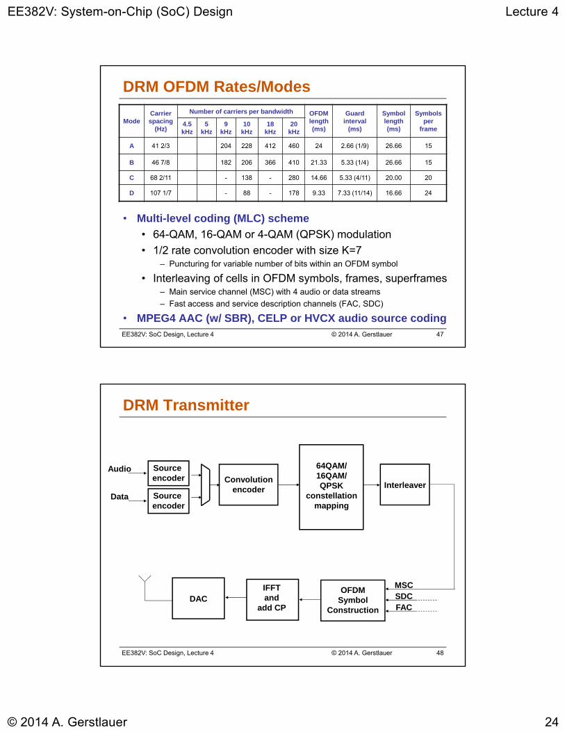
DRM OFDM Rates/Modes
• Multi-level coding (MLC) scheme
• 64-QAM, 16-QAM or 4-QAM (QPSK) modulation
• 1/2 rate convolution encoder with size K=7– Puncturing for variable number of bits within an OFDM symbol
• Interleaving of cells in OFDM symbols, frames, superframes– Main service channel (MSC) with 4 audio or data streams
– Fast access and service description channels (FAC, SDC)
• MPEG4 AAC (w/ SBR), CELP or HVCX audio source coding
ModeCarrier spacing
(Hz)
Number of carriers per bandwidth OFDM length (ms)
Guard interval
(ms)
Symbol length (ms)
Symbols per
frame4.5 kHz
5 kHz
9 kHz
10 kHz
18 kHz
20 kHz
A 41 2/3 204 228 412 460 24 2.66 (1/9) 26.66 15
B 46 7/8 182 206 366 410 21.33 5.33 (1/4) 26.66 15
C 68 2/11 - 138 - 280 14.66 5.33 (4/11) 20.00 20
D 107 1/7 - 88 - 178 9.33 7.33 (11/14) 16.66 24
EE382V: SoC Design, Lecture 4 © 2014 A. Gerstlauer 48
Source encoder Convolution
encoder Interleaver
64QAM/16QAM/QPSK
constellationmapping
OFDM Symbol
Construction
IFFTand
add CP
Audio
DAC
DRM Transmitter
Source encoder
Data
MSCSDCFAC
EE382V: System-on-Chip (SoC) Design Lecture 4
© 2014 A. Gerstlauer 25
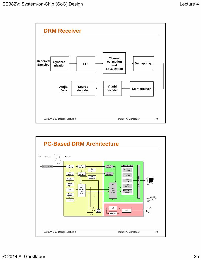
EE382V: SoC Design, Lecture 4 © 2014 A. Gerstlauer 49
Synchro-nization
Channelestimation
and equalization
FFT Demapping
DeinterleaverViterbi
decoderSourcedecoder
ReceivedSamples
Audio,Data
DRM Receiver
EE382V: SoC Design, Lecture 4 © 2014 A. Gerstlauer 50
PC-Based DRM Architecture
EE382V: System-on-Chip (SoC) Design Lecture 4
© 2014 A. Gerstlauer 26
EE382V: SoC Design, Lecture 4 © 2014 A. Gerstlauer 51
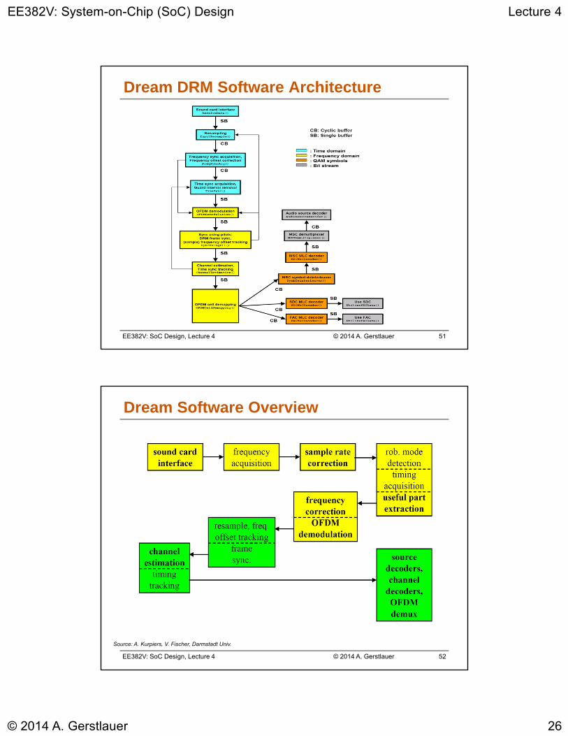
Dream DRM Software Architecture
EE382V: SoC Design, Lecture 4 © 2014 A. Gerstlauer 52
Dream Software Overview
Source: A. Kurpiers, V. Fischer, Darmstadt Univ.
EE382V: System-on-Chip (SoC) Design Lecture 4
© 2014 A. Gerstlauer 27
EE382V: SoC Design, Lecture 4 © 2014 A. Gerstlauer 53
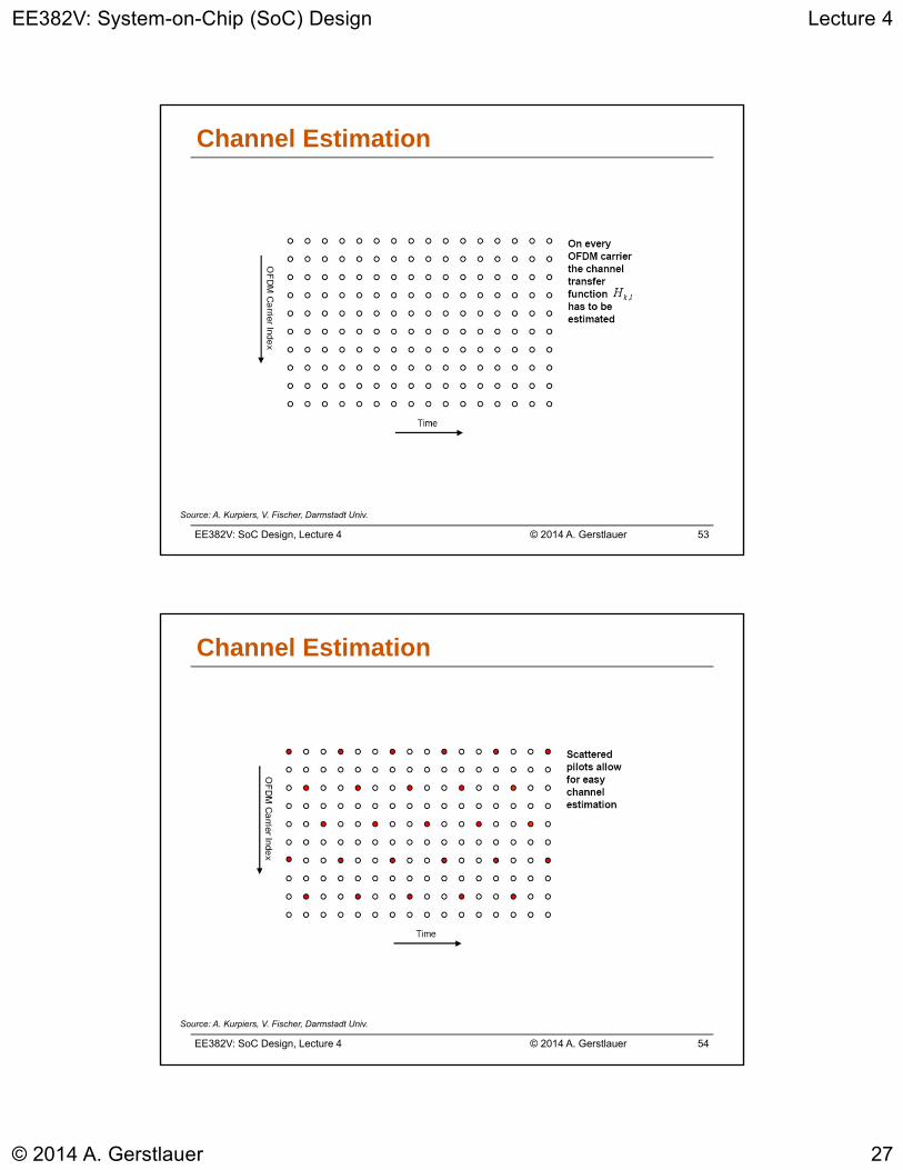
Channel Estimation
Source: A. Kurpiers, V. Fischer, Darmstadt Univ.
EE382V: SoC Design, Lecture 4 © 2014 A. Gerstlauer 54
Channel Estimation
Source: A. Kurpiers, V. Fischer, Darmstadt Univ.
EE382V: System-on-Chip (SoC) Design Lecture 4
© 2014 A. Gerstlauer 28
EE382V: SoC Design, Lecture 4 © 2014 A. Gerstlauer 55
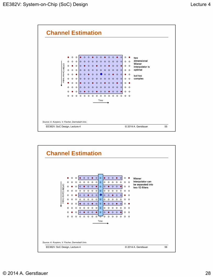
Channel Estimation
Source: A. Kurpiers, V. Fischer, Darmstadt Univ.
EE382V: SoC Design, Lecture 4 © 2014 A. Gerstlauer 56
Channel Estimation
Source: A. Kurpiers, V. Fischer, Darmstadt Univ.

EE382V: System-on-Chip (SoC) Design Lecture 4
© 2014 A. Gerstlauer 29
EE382V: SoC Design, Lecture 4 © 2014 A. Gerstlauer 57
Channel Estimation: Wiener Interpolation
Source: A. Kurpiers, V. Fischer, Darmstadt Univ.
EE382V: SoC Design, Lecture 4 © 2014 A. Gerstlauer 58
Channel Estimation
Source: A. Kurpiers, V. Fischer, Darmstadt Univ.
EE382V: System-on-Chip (SoC) Design Lecture 4
© 2014 A. Gerstlauer 30
EE382V: SoC Design, Lecture 4 © 2014 A. Gerstlauer 59
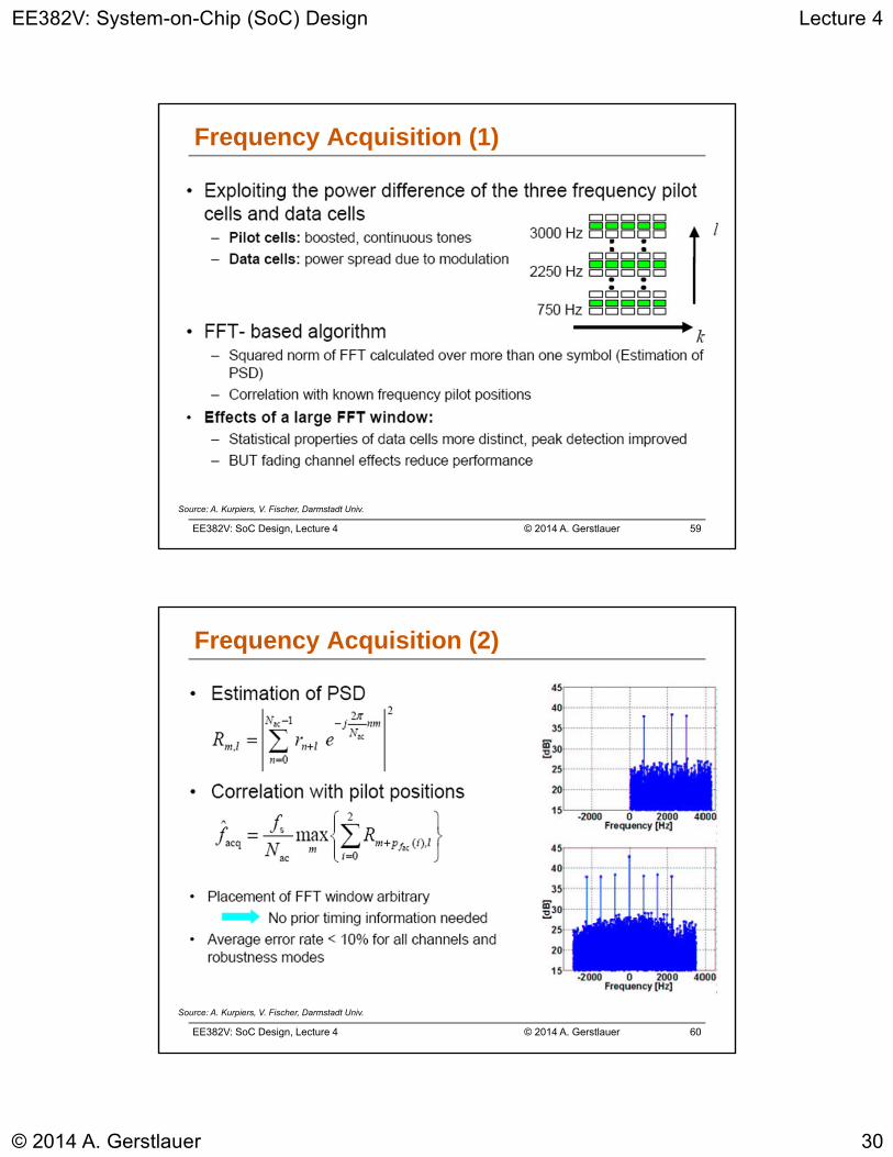
Frequency Acquisition (1)
Source: A. Kurpiers, V. Fischer, Darmstadt Univ.
EE382V: SoC Design, Lecture 4 © 2014 A. Gerstlauer 60
Frequency Acquisition (2)
Source: A. Kurpiers, V. Fischer, Darmstadt Univ.
EE382V: System-on-Chip (SoC) Design Lecture 4
© 2014 A. Gerstlauer 31
EE382V: SoC Design, Lecture 4 © 2014 A. Gerstlauer 61
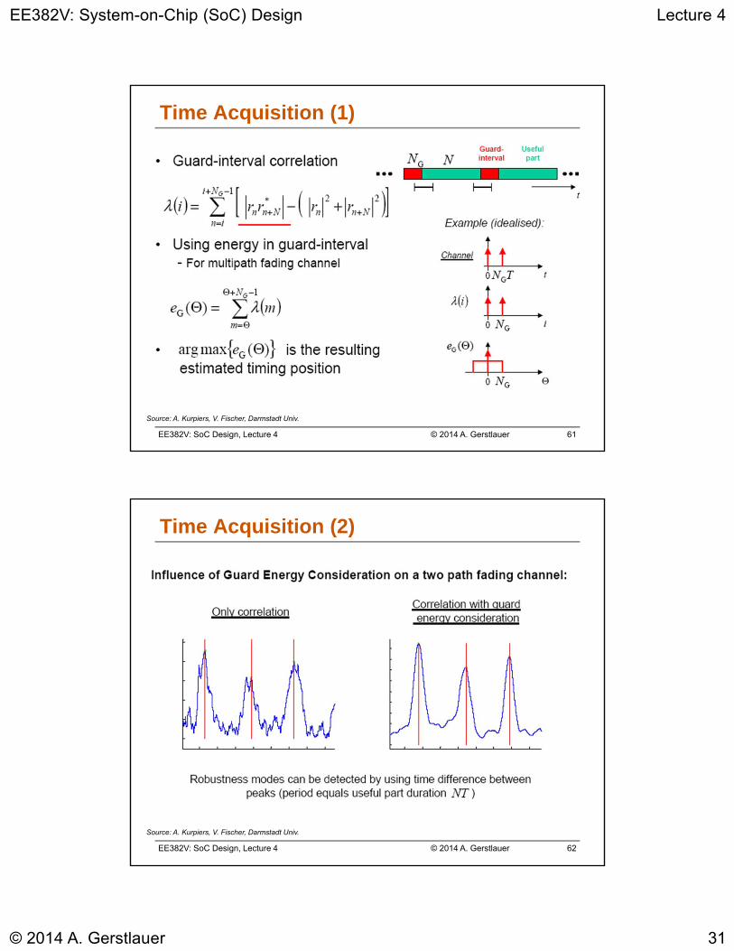
Time Acquisition (1)
Source: A. Kurpiers, V. Fischer, Darmstadt Univ.
EE382V: SoC Design, Lecture 4 © 2014 A. Gerstlauer 62
Time Acquisition (2)
Source: A. Kurpiers, V. Fischer, Darmstadt Univ.
EE382V: System-on-Chip (SoC) Design Lecture 4
© 2014 A. Gerstlauer 32
EE382V: SoC Design, Lecture 4 © 2014 A. Gerstlauer 63
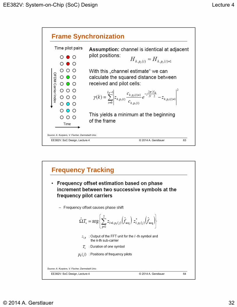
Frame Synchronization
Source: A. Kurpiers, V. Fischer, Darmstadt Univ.
EE382V: SoC Design, Lecture 4 © 2014 A. Gerstlauer 64
Frequency Tracking
Source: A. Kurpiers, V. Fischer, Darmstadt Univ.
EE382V: System-on-Chip (SoC) Design Lecture 4
© 2014 A. Gerstlauer 33
EE382V: SoC Design, Lecture 4 © 2014 A. Gerstlauer 65
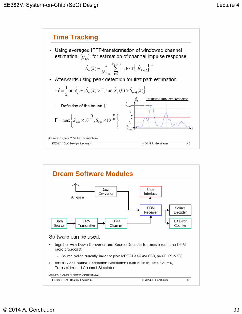
Time Tracking
Source: A. Kurpiers, V. Fischer, Darmstadt Univ.
EE382V: SoC Design, Lecture 4 © 2014 A. Gerstlauer 66
Dream Software Modules
Source: A. Kurpiers, V. Fischer, Darmstadt Univ.

EE382V: System-on-Chip (SoC) Design Lecture 4
© 2014 A. Gerstlauer 34
EE382V: SoC Design, Lecture 4 © 2014 A. Gerstlauer 67
Summary
• DRM Receiver operates close to the possible limits
• Try to close the gap between ideal channel estimation and realization
– ICI compensation
– Decision directed channel estimation
– Noise cancellation for narrow-band interference
• Software runs real-time on a 700 MHz Pentium PC
• Improve to allow „background“ reception– Use SIMD instructions to speed up (MMX, SSE etc.)
– Improve „pipelining“ of the algorithms to make acquisition phase shorter
• Source Decoder (faad2) needs additional features(SBR, CELP, HVXC)
Top Related