


Languages
Pages
Legal

ECTA-CEfiC GuidElinEs for EquipmEnT for ThE TrAnsporT of dry bulk CArGo, To bE disChArGEd by TippinG
EQUIPMENT FOR THE TRANSPORT OF DRY BULK CARGO, TO BE DISCHARGED BY TIPPING2
disClAimEr
This document is intended for information only and sets out guidelines for equipment for transport of dry bulk cargo, to be discharged by tipping. The information contained in these guidelines is provided in good faith and, while it is accurate as far as the authors are aware, no representations or warranties are made with regard to its completeness. It is not intended to be a comprehensive guide to all the transport equipment used for dry bulk cargo. No responsibility will be assumed by the participating associations, Cefic and ECTA, in relation to the information contained in these Guidelines.
3ECTA-CEFIC GUIDELINES
TAblE of ConTEnTs
DISCLAIMER 2
INTRODUCTION 4
OBJECTIVE AND SCOPE 4
1. EQUIPMENT SPECIFICATIONS FOR TIPPING SILO ROAD TANKERS
AND PRESSURISED SILO / BOX CONTAINERS 6
1.1 General specifications for tank and accessories 6
1.2 Top manholes 6
1.3 Handrail / walkway 6
1.4 Blower / compressor 7
1.5 Discharge filter equipment 7
1.6 Thermometer 8
1.7 Air conducts 8
1.8 Discharge manhole and valve 8
1.9 Hoses and couplings 8
2. EQUIPMENT SPECIFICATIONS FOR UNPRESSURISED DRY BULK BOX CONTAINERS 9
2.1 General specifications for the body of the container and accessories 9
2.2 Gaskets and valves 9
2.3 Top manholes 9
2.4 Handrail / walkways 10
2.5 Hoses / blower / compressor / discharge air filter / air supply lines / couplings 10
3. TIPPING CHASSIS 10
3.1 Twist locks and landing legs 10
3.2 Rotary feeder 10
3.3 Earthing wire on the chassis 10
CONTACTS 11
TAblE of ConTEnTs
EQUIPMENT FOR THE TRANSPORT OF DRY BULK CARGO, TO BE DISCHARGED BY TIPPING4
inTroduCTion
The effort to continually improve safety during transport and the associated handling of chemicals is part of the overall objective of both the chemical industry and the transport industry to operate in accordance with the Guiding Principles of Responsible Care.
These Guidelines have been developed with the aim of offering guidance regarding specifications for transport equipment specifically designed for the transport of dry bulk cargo, which is to be discharged by tipping.
Companies may decide to apply the guidelines either in full or in part, taking into account specific circumstances and own requirements.
Compliance with any applicable national and international regulations always takes precedence over adhering to the recommendations made in the present Guidelines.
obJECTiVE And sCopE
The objective of these Guidelines is to describe the equipment designed for the transport of dry bulk chemical cargo, which is discharged by tipping, such as silo trailers and dry bulk containers.
The following types of equipment are included in the scope of these Guidelines:
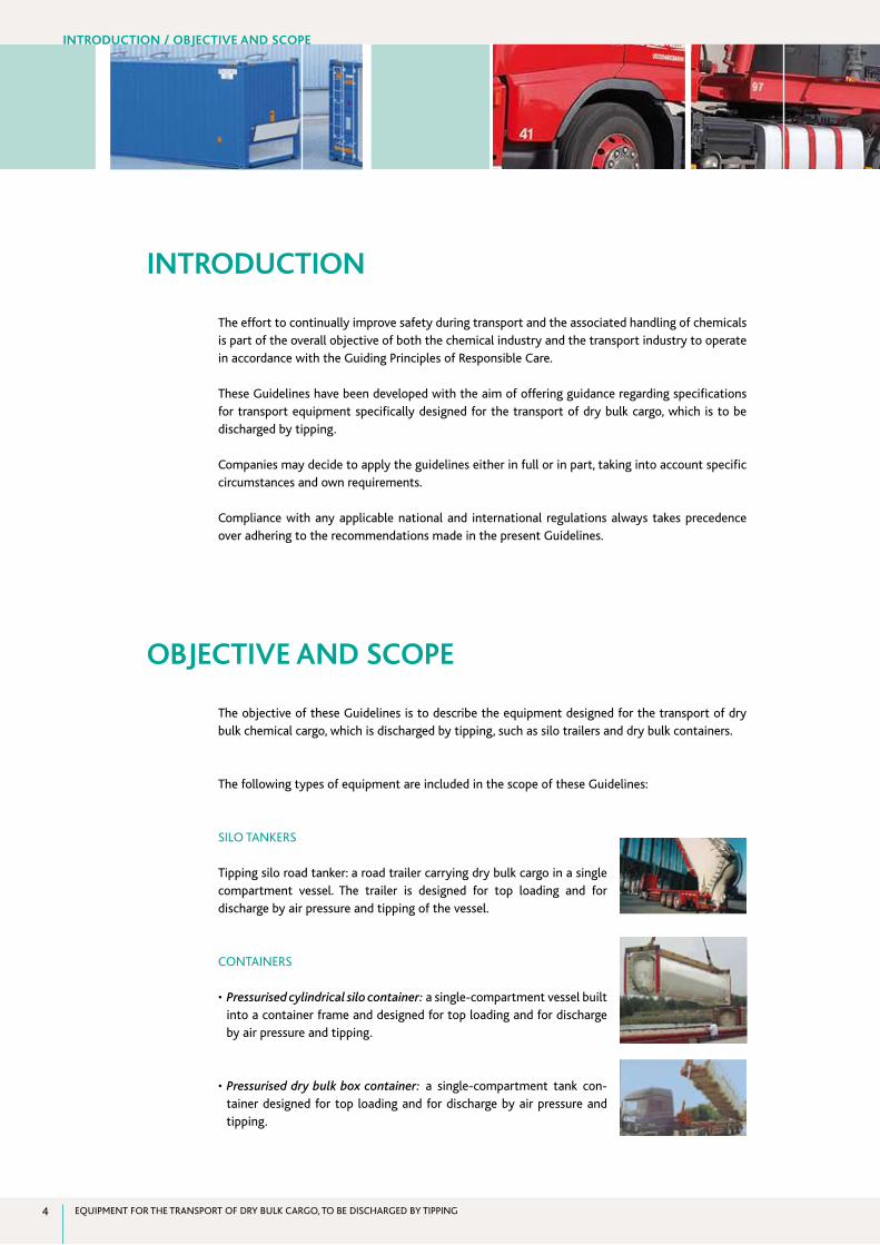
SILO TANKERS
Tipping silo road tanker: a road trailer carrying dry bulk cargo in a single compartment vessel. The trailer is designed for top loading and for discharge by air pressure and tipping of the vessel.
CONTAINERS
•Pressurised cylindrical silo container: a single-compartment vessel built into a container frame and designed for top loading and for discharge by air pressure and tipping.
•Pressurised dry bulk box container: a single-compartment tank con-tainer designed for top loading and for discharge by air pressure and tipping.
inTroduCTion / obJECTiVE And sCopE
ECTA-CEFIC GUIDELINES 5
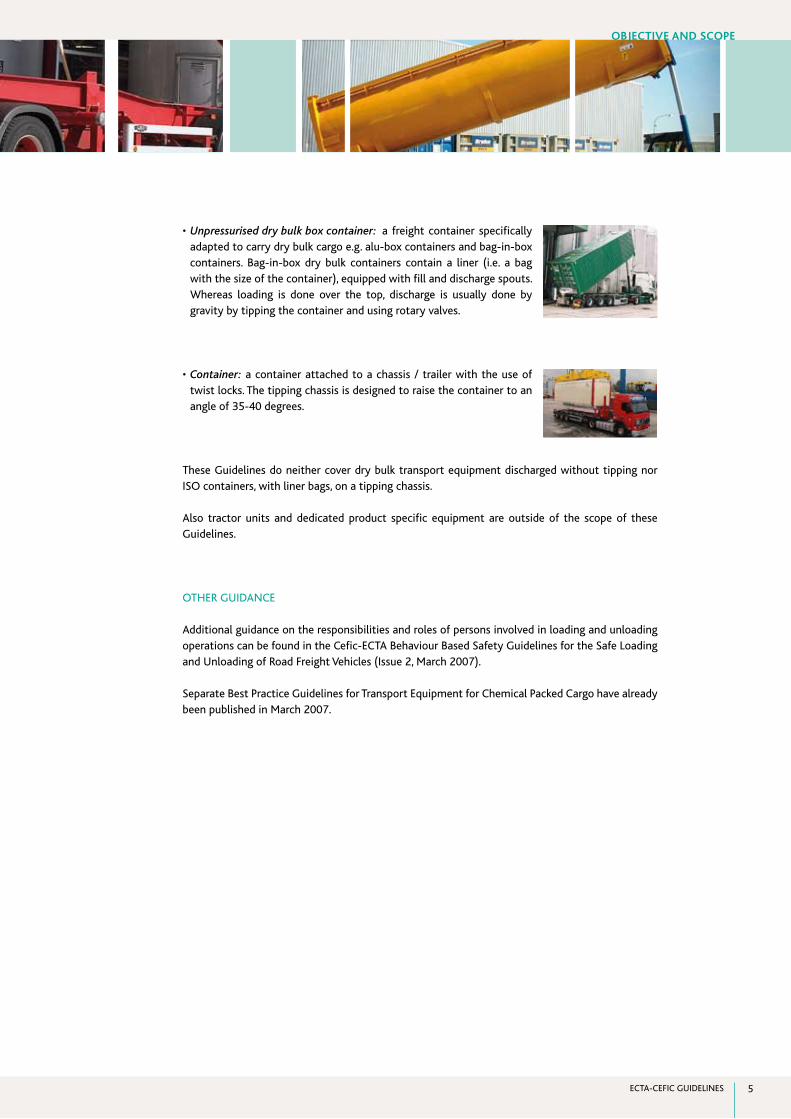
•Unpressurised dry bulk box container: a freight container specifically adapted to carry dry bulk cargo e.g. alu-box containers and bag-in-box containers. Bag-in-box dry bulk containers contain a liner (i.e. a bag with the size of the container), equipped with fill and discharge spouts. Whereas loading is done over the top, discharge is usually done by gravity by tipping the container and using rotary valves.
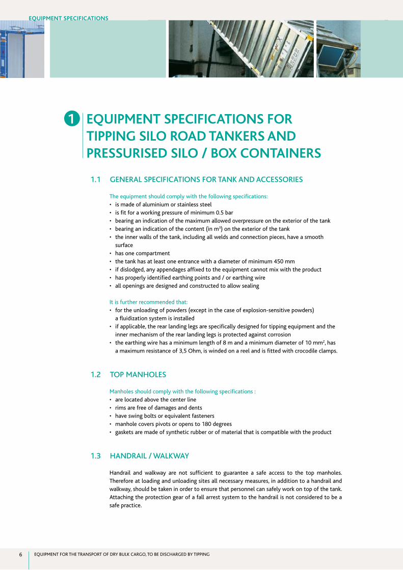
•Container: a container attached to a chassis / trailer with the use of twist locks. The tipping chassis is designed to raise the container to an angle of 35-40 degrees.
These Guidelines do neither cover dry bulk transport equipment discharged without tipping nor ISO containers, with liner bags, on a tipping chassis.
Also tractor units and dedicated product specific equipment are outside of the scope of these Guidelines.
OTHER GUIDANCE
Additional guidance on the responsibilities and roles of persons involved in loading and unloading operations can be found in the Cefic-ECTA Behaviour Based Safety Guidelines for the Safe Loading and Unloading of Road Freight Vehicles (Issue 2, March 2007).
Separate Best Practice Guidelines for Transport Equipment for Chemical Packed Cargo have already been published in March 2007.
obJECTiVE And sCopE
EQUIPMENT FOR THE TRANSPORT OF DRY BULK CARGO, TO BE DISCHARGED BY TIPPING6
1 EquipmEnT spECifiCATions for TippinG silo roAd TAnkErs And prEssurisEd silo / boX ConTAinErs
1.1 GENERAL SPECIFICATIONS FOR TANK AND ACCESSORIES The equipment should comply with the following specifications:• ismadeofaluminiumorstainlesssteel• isfitforaworkingpressureofminimum0.5bar• bearinganindicationofthemaximumallowedoverpressureontheexteriorofthetank• bearinganindicationofthecontent(inm3) on the exterior of the tank• theinnerwallsofthetank,includingallweldsandconnectionpieces,haveasmooth
surface• hasonecompartment• thetankhasatleastoneentrancewithadiameterofminimum450mm• ifdislodged,anyappendagesaffixedtotheequipmentcannotmixwiththeproduct• hasproperlyidentifiedearthingpointsand/orearthingwire• allopeningsaredesignedandconstructedtoallowsealing
It is further recommended that:• fortheunloadingofpowders(exceptinthecaseofexplosion-sensitivepowders)
a fluidization system is installed• ifapplicable,therearlandinglegsarespecificallydesignedfortippingequipmentandthe
inner mechanism of the rear landing legs is protected against corrosion• theearthingwirehasaminimumlengthof8mandaminimumdiameterof10mm2, has
a maximum resistance of 3,5 Ohm, is winded on a reel and is fitted with crocodile clamps.
1.2 TOP MANHOLES Manholes should comply with the following specifications :• arelocatedabovethecenterline• rimsarefreeofdamagesanddents• haveswingboltsorequivalentfasteners• manholecoverspivotsoropensto180degrees• gasketsaremadeofsyntheticrubberorofmaterialthatiscompatiblewiththeproduct
1.3 HANDRAIL / WALKWAY Handrail and walkway are not sufficient to guarantee a safe access to the top manholes. Therefore at loading and unloading sites all necessary measures, in addition to a handrail and walkway, should be taken in order to ensure that personnel can safely work on top of the tank. Attaching the protection gear of a fall arrest system to the handrail is not considered to be a safe practice.
EquipmEnT spECifiCATions
ECTA-CEFIC GUIDELINES 7
If the top of the tank is not flat, the tank must be fitted with an access ladder and a safety handrail along the walkway.
Walkways need to have an anti-slip surface or structure.
When equipped with a handrail and walkway, the following minimum specifications should be complied with:• theminimumwidthofthewalkwayis400mm• theminimumheightofthehandrailis1000mmalongtheentirewalkway• additionalprotectionexistsathalfoftheheightofthehandrail(e.g.asteelcable)• thehandrailiscapabletowithstandahorizontaltensionof300Ninalldirections• thehandrailiserectedbeforesteppingonthewalkway.
note: As the majority of pressurised box containers is not fitted with a handrail, it is necessary that loading and unloading sites take all necessary measures (e.g. safety harness, safety platform) in order to ensure that personnel can safely access and work on top of the container.
1.4 BLOWER / COMPRESSOR The safest and the best solution for guaranteeing product integrity is the use of a product-dedicated blower / compressor, supplied by the loading or unloading site.
If a blower / compressor is however provided with the vehicle, it should comply with the following specifications:• doesnotcontainoil• allmovingpartsareproperlyprotectedbyasafetycover• isfittedwithafilter,filteringtheincomingair(tobeinspectedatleastonceayear)of
which the air inlet is placed away from the exhaust of the vehicle engine
note: Attention is to be paid to the noise level resulting from the whole unloading process and possible improvements should be discussed with the unloading sites.
1.5 DISCHARGE FILTER EQUIPMENT The following specifications should be complied with:
1.5.1 disChArGE Air filTEr
• ismadeofstainlesssteeloraluminium• isinstalledintheairsupplylineafterthecompressorbutbeforethemanifold• issealable
FILTER ELEMENT• ismadeofsinteredstainlesssteel• isshock-proofandretainsparticleslargerthan5microns• canbeeasilyremovedforcleaningandinspectionpurposes
EquipmEnT spECifiCATions
EQUIPMENT FOR THE TRANSPORT OF DRY BULK CARGO, TO BE DISCHARGED BY TIPPING8
1.5.2 mAnomETEr
• Amanometerisinstalledbetweenthedischargeairfilterandthemanifoldandalsothetank is equipped with a manometer.
note: Some products may require specific unloading conditions related to temperature and pressure. Compressors with intercoolers or the use of a tank by-pass may be considered as best practice alternatives.
• Themanometerisadaptedtotheflowrateofthecompressor.
1.6 THERMOMETER A thermometer is installed close to the manifold.
1.7 AIR CONDUCTS Air conducts after the discharge air filter, whether flexible or fixed to the equipment, should meet the following specifications:• aremadeofaluminium,stainlesssteelorsyntheticrubber• areconstructedinsuchawayastoallowvisualinspectionatallpoints• atleastonesafetyreliefvalveisinstalledbetweenthefilterandthetankwithanadequate
capacity, and with pressure settings in line with the design of the tank• atleastonenon-returnvalveisinstalledafterthedischargeairfilterinordertoprevent
product particles entering the filter when the blower is turned off
1.8 DISCHARGE MANHOLE AND VALVE The following specifications should be complied with:
1.8.1 disChArGE mAnholE
• islocatedinthecenterlineofthetank• hasadiameterofatleast450mm• rimsarefreeofdamagesanddents• isclosedwithatleastfourswingbolts• isproperlysecuredwhenopened• gasketsaremadeofsyntheticrubberorofmaterialthatiscompatiblewiththeproduct
1.8.2 disChArGE VAlVE
• isabutterflyvalvemadeofstainlesssteeloraluminium• allowsforeasyinspection• valvegaskets,ifpresent,aremadeofsyntheticrubberorofamaterialthatiscompatible
with the product
1.9 HOSES AND COUPLINGS 1.9.1 hosEs
The safest and the best solution for guaranteeing product integrity is the use of product-dedicated hoses and couplings, supplied at the unloading location.
EquipmEnT spECifiCATions
ECTA-CEFIC GUIDELINES 9
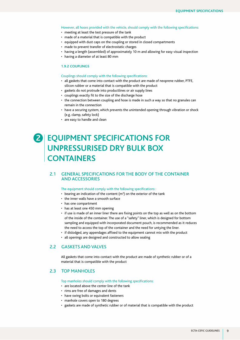
However, all hoses provided with the vehicle, should comply with the following specifications:• meetingatleastthetestpressureofthetank• madeofamaterialthatiscompatiblewiththeproduct• equippedwithdustcapsonthecouplingorstoredinclosedcompartments• madetopreventtransferofelectrostaticcharges• havingalength(assembled)ofapproximately10mandallowingforeasyvisualinspection• havingadiameterofatleast80mm
1.9.2 CouplinGs
Couplings should comply with the following specifications:• allgasketsthatcomeintocontactwiththeproductaremadeofneoprenerubber,PTFE,
silicon rubber or a material that is compatible with the product• gasketsdonotprotrudeintoproductlinesorairsupplylines• couplingsexactlyfittothesizeofthedischargehose• theconnectionbetweencouplingandhoseismadeinsuchawaysothatnogranulescan
remain in the connection• haveasecuringsystem,whichpreventstheunintendedopeningthroughvibrationorshock
(e.g. clamp, safety lock)• areeasytohandleandclean
2 EquipmEnT spECifiCATions for unprEssurisEd dry bulk boX ConTAinErs
2.1 GENERAL SPECIFICATIONS FOR THE BODY OF THE CONTAINER AND ACCESSORIES
The equipment should comply with the following specifications :• bearinganindicationofthecontent(m3) on the exterior of the tank• theinnerwallshaveasmoothsurface• hasonecompartment• hasatleastone450mmopening• ifuseismadeofaninnerlinertherearefixingpointsonthetopaswellasonthebottom
of the inside of the container. The use of a “safety” liner, which is designed for bottom sampling and equipped with incorporated document pouch, is recommended as it reduces the need to access the top of the container and the need for untying the liner.• ifdislodged,anyappendagesaffixedtotheequipmentcannotmixwiththeproduct• allopeningsaredesignedandconstructedtoallowsealing
2.2 GASKETS AND VALVES
All gaskets that come into contact with the product are made of synthetic rubber or of a material that is compatible with the product
2.3 TOP MANHOLES
Top manholes should comply with the following specifications:• arelocatedabovethecenterlineofthetank• rimsarefreeofdamagesanddents• haveswingboltsorequivalentfasteners• manholecoversopento180degrees• gasketsaremadeofsyntheticrubberorofmaterialthatiscompatiblewiththeproduct
EquipmEnT spECifiCATions
EQUIPMENT FOR THE TRANSPORT OF DRY BULK CARGO, TO BE DISCHARGED BY TIPPING10
2.4 HANDRAIL / WALKWAYS
Loading and unloading sites should take all necessary measures to ensure that personnel can safely work on top of the container. Handrail and walkway are not sufficient to guarantee a safe access to the top manholes. The majority of this equipment is not fitted with a handrail. Walkways should have an anti-slip surface or structure.
2.5 HOSES / BLOWER / COMPRESSOR / DISCHARGE AIR FILTER / AIR SUPPLY LINES / COUPLINGS
Requirements as described in Chapter 1 are applicable.
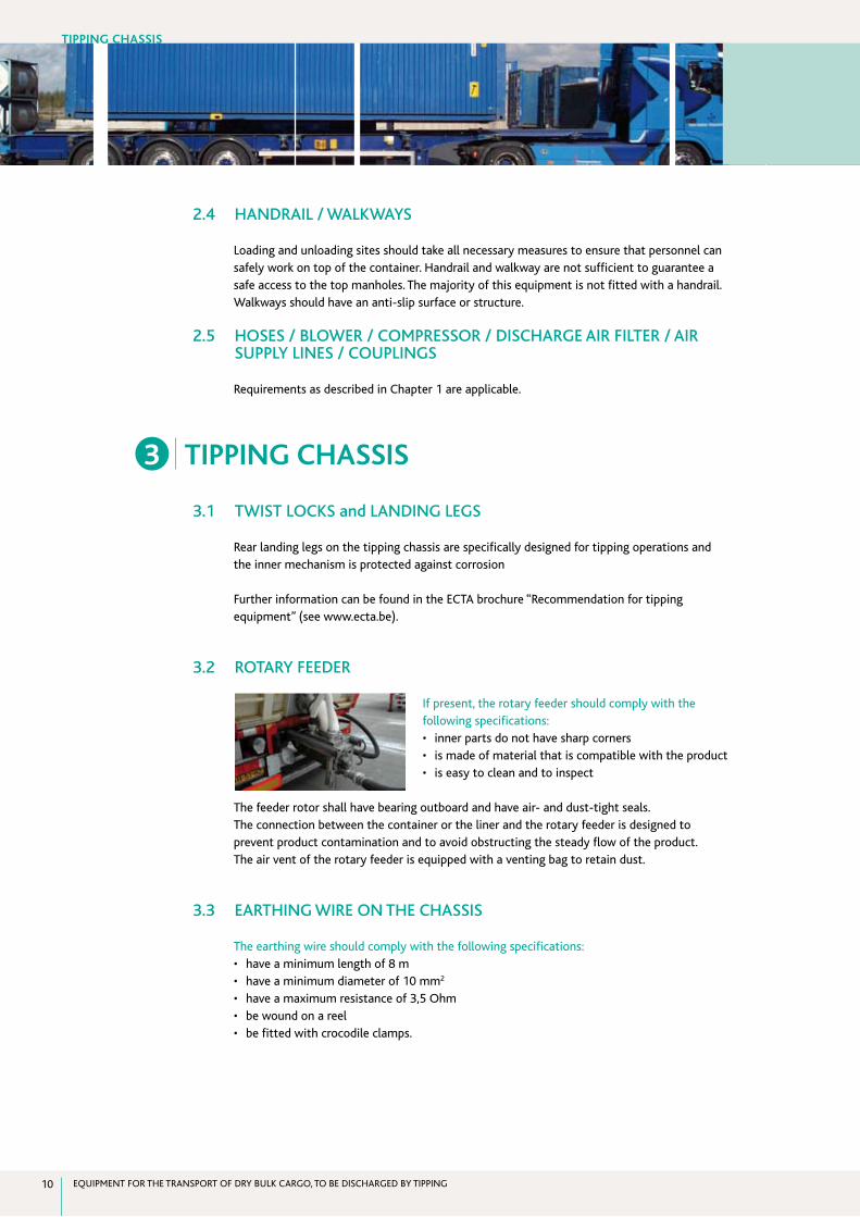
3 TippinG ChAssis
3.1 TWIST LOCKS and LANDING LEGS
Rear landing legs on the tipping chassis are specifically designed for tipping operations and the inner mechanism is protected against corrosion
Further information can be found in the ECTA brochure “Recommendation for tipping equipment” (see www.ecta.be).
3.2 ROTARY FEEDER
If present, the rotary feeder should comply with the following specifications:• innerpartsdonothavesharpcorners• ismadeofmaterialthatiscompatiblewiththeproduct• iseasytocleanandtoinspect
The feeder rotor shall have bearing outboard and have air- and dust-tight seals.The connection between the container or the liner and the rotary feeder is designed to prevent product contamination and to avoid obstructing the steady flow of the product.The air vent of the rotary feeder is equipped with a venting bag to retain dust.
3.3 EARTHING WIRE ON THE CHASSIS
The earthing wire should comply with the following specifications:• haveaminimumlengthof8m• haveaminimumdiameterof10mm2
• haveamaximumresistanceof3,5Ohm• bewoundonareel• befittedwithcrocodileclamps.
TippinG ChAssis
ECTA-CEFIC GUIDELINES 11
sergio menegazzi
LyondellBasell Industries
Brühler Straße 60
50389 Wesseling
Germany
T + 49 (0) 2236 72 6227
F + 49 (0) 2236 72 46227
frank huysmans
Bruhn Spedition NV
Sint Pietersvliet 3 bus 6
2000 Antwerpen
Belgium
T + 32 (0) 3 224 84 84
F + 32 (0) 3 226 26 45
klaus Wessing
Alfred Talke GmbH & Co. KG
Max-Planck-Str. 20
50354 Hürth
Germany
T + 49 (0) 2233 599 555
F + 49 (0) 2233 599 263
stefan seibel
Evonik Services GmbH
Procurement Services Logistics
Weissfrauenstr. 9
60287 Frankfurt / Main
Germany
T + 49 (0) 6921 82 575
F + 49 (0) 6921 862 575
e mail [email protected]
Jos ooms
ExxonMobil
Biezenhoed 2
2450 Meerhout
Belgium
T + 32 (0) 14 863150
F + 32 (0) 14 867088
marc houtermans
SABIC EuroPetrochemicals B.V.
P.O. Box 5151
6130 PD Sittard
The Netherlands
T + 31 (0) 46 476 8205
F + 31 (0) 46 476 2255
frans schuitemaker
Nijhof-Wassink B.V.
P.O. Box 22
7460 AA Rijssen
The Netherlands
T + 31 (0) 548 538000
F + 31 (0) 548 538001
ConTACTs

CEfiC AISBL - EuropEAn ChEmiCAl indusTry CounCilAvenue E. van Nieuwenhuyselaan 41160 Brussels - BelgiumT +32 2 676 72 11F +32 2 676 73 00www.cefic.org
EuropEAn ChEmiCAl TrAnsporT AssoCiATion - AISBL
Avenue de Tervurenlaan 2701150 Brussels - BelgiumT +32 2 741 86 67F +32 2 741 86 82www.ecta.be
Top Related