


Languages
Pages
Legal

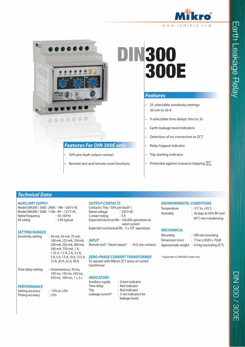
DIN300DIN300E
Technical DataAUXILIARY SUPPLYModel DIN300 / 300E -240A : 198 ~ 265 V ACModel DIN300 / 300E -110A : 94 ~ 127 V ACRated frequency : 50 / 60 HzVA rating : 3 VA typical
SETTING RANGESSensitivity setting : 30 mA, 50 mA, 75 mA,
100 mA, 125 mA, 150 mA, 200 mA, 250 mA, 300 mA, 500 mA, 750 mA, 1 A, 1.25 A, 1.5 A, 2 A, 2.5 A, 3 A, 5 A, 7.5 A, 10 A, 12.5 A, 15 A, 20 A, 25 A, 30 A.
Time delay setting : Instantaneous, 50 ms, 100 ms, 150 ms, 250 ms, 350 ms, 500 ms, 1 s, 3 s.
PERFORMANCESetting accuracy : -15% to +0%Timing accuracy : ±5%
ENVIRONMENTAL CONDITIONSTemperature : -5˚C to +55˚CHumidity : 56 days at 93% RH and
40˚C non-condensing
MECHANICALMounting : DIN rail mountingDimension (mm) : 71(w) x 85(h) x 70(d)
Approximate weight
:
0.4 kg (excluding ZCT)
* Applicable to DIN300E model only
OUTPUT CONTACTSContacts ( Trip / 50% pre-fault* )Rated voltage : 250 V ACContact rating : 5 AExpected electrical life : 100,000 operations at
rated currentExpected mechanical life : 5 x 10⁶ operations
INPUTRemote test* / Reset inputs* : N.O. dry contacts
To operate with Mikro’s ZCT series of current transformer
INDICATORSAuxiliary supply : Green indicatorTime delay : Red indicatorTrip : Red indicatorLeakage current* : 5 red indicators for
leakage levels
Earth Leakage R
elayD
IN 300 / 300E
Features
• 25 selectable sensitivity settings: 30 mA to 30 A
• 9 selectable time delays: 0ms to 3s
• Earth leakage level indicators
• Detection of no connection to ZCT
• Relay tripped indicator
• Trip starting indicator
• Protected against nuisance tripping
Features For DIN 300E only
• 50% pre-fault output contact
• Remote test and remote reset functions

Earth Leakage Relay
Case Dimensions
Ordering Information
DIN300 - 240A For 50 Hz system, auxiliary voltage 240 V AC DIN300 - 110A For 50 Hz system, auxiliary voltage 110 V ACDIN300E - 240A For 50 Hz system, auxiliary voltage 240 V AC DIN300E - 110A For 50 Hz system, auxiliary voltage 110 V ACDIN300 - 240A6 For 60 Hz system, auxiliary voltage 240 V AC DIN300 - 110A6 For 60 Hz system, auxiliary voltage 110 V ACDIN300E - 240A6 For 60 Hz system, auxiliary voltage 240 V AC DIN300E - 110A6 For 60 Hz system, auxiliary voltage 110 V AC
MODEL DESCRIPTION
71mm
71mm
30mm 20mm 20mm
45mm
85mm
20mm
20mm
Front view
Side view
L1 L2 L3 N
1 2 3 4 5 6
8 9 10 11 12 13
7
14
L NAUX
S2
S1
TRIP CONTACT50% PRE-FAULT CONTACT
LOAD
SHUNTTRIP
REM
OTE
RES
ET
REM
OTE
TES
T
COMCOM NO NCNCNO
PE
The EARTH wire must not pass through the ZCT
L1 L2 L3 N
1 2 3 4 5 6
8 9 10 11 12 13
7
14
L NAUX
S2
S1
TRIP CONTACT
LOAD
SHUNTTRIP
COM NO NC
PE
The EARTH wire must not pass through the ZCT
Typical Application Diagram For DIN 300E
Typical Application Diagram For DIN 300
DIN 300 / 300E
Top Related