


Languages
Pages
Legal


E-SALE CATALOGUE-HFO/LDO/HSD FUELED MAN B&W DG POWER
PLANT
PUNE, INDIA
CONDUCTED BY
mjunction services limited

SALE OF 3 X 11.65 MW -HFO/LDO/HSD FUELED MAN B&W DG POWER PLANT &
SPARES ITEMS – TATA MOTORS
Online Sale Event conducted by mjunction services ltd
“Being sold on “AS IS WHERE IS & NO COMPLAINT BASIS”
Table – 1
Mandate Number: VJ15215497
Seller: TATA MOTORS LIMITED
Online Event
website: www.metaljunction.com
Date & Time: On 05-04-2016 online sale event will be held at 2 PM, details will be
communicated to participants who qualify
Inspection Date &
Time:
01-02-2016 to 31-03-2016 (on working days) with prior
appointment with concerned person from mjunction at least 2 days
before date of visit.
Inspection timings –
9am to 12 pm & 2 pm to 4.30 pm (Monday to Saturday only)
Location of
material:
Tata Motors Limited
Telco Road, K S B Chowk, MIDC Road, Pimpri, Pune-411018
Bank Guarantee:
Non-Interest bearing security deposit has to be submitted in the form
of Bank Guarantee to “Tata Motors Limited” (No other mode of
payment allowed for Bank Guarantee) Bank Guarantee Amount is
given in TABLE -3.
Bank details are below:

Contact Details:
mjunction services limited :
Mr. Satyavir : 08336925974 ; [email protected]
Auction Room No’s:
(033)66031760-72 (13 lines)
(033)44091760-72 (13 lines)
Contact person from TML
Mr. VV Joshi (Head CCE, Pune)
9011022583
Note:
I. Taxes and duties will be charged at the rates prevailing at the time of invoicing
II. Sale order & Delivery order shall be issued by Tata Motors Limited.
III. Proforma Invoice to be issued by TATA MOTORS LIMITED to the winning buyer
on price approval.
IV. Bidders will have to bid for the power plant and the spares separately even
though both (Power plant and spares) will be sold as a single lot.
Special Terms & Conditions:
Onsite Inspection:
i. Inspection will only be permitted by giving prior notification to the valuejunction
team at least 2 days before the date of visit. Refer to the Expression of Interest
document for inspection appended below in this catalogue.
ii. Interested customers are required to submit the duly filled in EOI (next page) &
submit the balance sheet of the previous financial year to mjunction before visiting
the site.
iii. Customers visiting the site are required to carry the following 2 items with them:
Photo identity proof of each visitor.
Company letterhead.

EXPRESSION OF INTEREST FOR INSPECTION
(To be printed on company letter head)
To
The Manager
Value junction
mjunction services limited
Godrej Waterside Building Tower 1
Sec-V, Salt Lake
Kolkata - 700091
REF.: Sale of HFO/LDO/HSD FUELED MAN B&W DG POWER PLANT & SPARES
ITEMS from Pune plant of TATA MOTORS LIMITED
Dear Sir,
As we are interested to participate in the upcoming online sale of used machineries at
Pune plant of TATA MOTORS LIMITED, we want to visit the site for detailed Inspection
on ________________.
We agree to follow all the safety norms of TATA MOTORS LIMITED inside the plant
during inspection. We are made aware that the Inspection by our company at the site is
to be completed by us within a maximum of one day and by a maximum of four people.
We are hereby submitting the last year’s Balance Sheet of our company and Company
Incorporation Certificate to “mjunction services limited” prior to the site visit.
We are providing the details of the personnel who will be visiting the site on behalf of
our company and submitting their official photo identity proof.
(A) Name of the Company :_______________________________________________________
(B) Address :_______________________________________________________
(C) Name of the Proprietor/CEO/MD/Director: ________________________________________

(D) Contact Telephone No : ______________________________________________________
(E) Mobile No. : ______________________________________________________
(F) FAX No. : ______________________________________________________
(G) E-Mail : ______________________________________________________
I / WE CONFIRM THAT I / WE ARE AWARE ABOUT THE TERMS & CONDITIONS FOR
INSPECTION AND THE ITEMS ON OFFER.
The Name & Detail of Persons who will be visiting the site:
1.
2.
3.
4.
Yours faithfully
For M/S
---------------------------------------
Signature of authorized person
With company seal Place: Date:
Note: This document can be scanned & sent to the following email address along with
the other documents to be submitted.
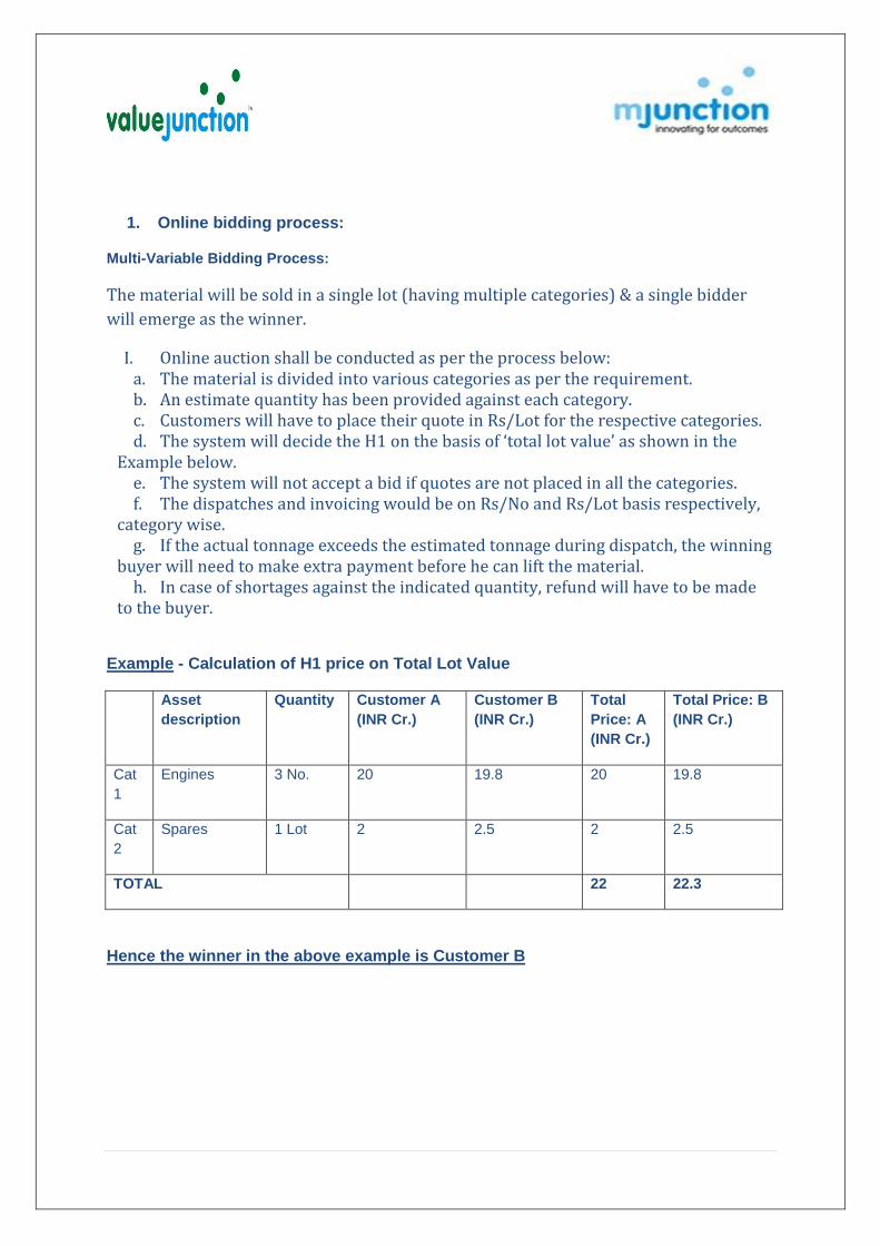
1. Online bidding process:
Multi-Variable Bidding Process:
The material will be sold in a single lot (having multiple categories) & a single bidder
will emerge as the winner.
I. Online auction shall be conducted as per the process below: a. The material is divided into various categories as per the requirement.b. An estimate quantity has been provided against each category.c. Customers will have to place their quote in Rs/Lot for the respective categories.d. The system will decide the H1 on the basis of ‘total lot value’ as shown in the
Example below. e. The system will not accept a bid if quotes are not placed in all the categories.f. The dispatches and invoicing would be on Rs/No and Rs/Lot basis respectively,
category wise. g. If the actual tonnage exceeds the estimated tonnage during dispatch, the winning
buyer will need to make extra payment before he can lift the material. h. In case of shortages against the indicated quantity, refund will have to be made
to the buyer.
Example - Calculation of H1 price on Total Lot Value
Asset
description
Quantity Customer A
(INR Cr.)
Customer B
(INR Cr.)
Total
Price: A
(INR Cr.)
Total Price: B
(INR Cr.)
Cat
1
Engines 3 No. 20 19.8 20 19.8
Cat
2
Spares 1 Lot 2 2.5 2 2.5
TOTAL 22 22.3
Hence the winner in the above example is Customer B

2. Details of Machines for Disposal at Pune Units are as under:
Equipment details:
Table: 2
Particulars Nos. Make/Details
Taxes (Over & above the basic price)
Engine 3
Man B & W, Germany Sr. No. - 1135016/1135017/1135018
Turbo Charger 6 Man B & W, Germany
Lube Oil Pump 3 Leistritz, Nuremberg, Germany
Jacket Cooling Water PHE 3 Alfa Laval
Charge Air Cooling Water PHE 3 Alfa Laval
Lube Oil PHE 3 Alfa Laval
Alternators 3 Siemens AG
Turning Gear Unit Motor 3 Flender (Germany)
Alternator Bearing Oil Cooling Pump
3 Rickmeier
Charge Air Cooling Water Pump 3 Allweiler AG
Nozzle Cooling Water Pump 3 Grundfos
Jacket Water Cooling Pump & Motor
3 Allweiler AG/ Barat Bijlee
Jacket Water Circulation Pump Secondary & Motor
3 Allweiler AG/Gaudfos
Lube Oil Centrifuge 3
Westfalia Make + 3 Motors (Crompton Greaves 1 No., Siemens 2 Nos.)
Lube Oil Separator Feed Pump 3 Crompton Greaves
HFO Centrifuge 3
Westfalia Make + 3 Motors (Crompton Greaves 1 No., Siemens 2 Nos.)
Governor 3 Woodward
Cylinder Lube Oil Pumps 6 Grundfos
Valve Seat Lube Oil Pumps 6 VEM Germany
HFO Module Feed Pump 3 IMO AB Sweeden + Motor ( Brook Hansen Make)
HFO Circulation Pump 1 IMO AB Sweeden + Motor ( Brook Hansen Make)

Non IBR HFO Fired Boilers 3 Elite Engineers
DG Chimney 3 Nos + 3 DG Silencers + 1 Boiler Chimney
Sterling Strips, 4 Sections, Self Supporting, Bottom Section Tapered from 4 mt Dia to 2 mt Dia
Lube Oil Auto Filter 3 Boll & Kirch + Motor (Stefphan)
Intake Air Filter 3 Locker Air Maze + Motor (Parvalux)
Raw Water Pumps 4 Kirloskar Brothers Limited + Motor (Siemens)
Air Compressors 4 Ingersoll Rand + Motor (Bharat Bijlee)
Cooling Tower 1 Paharpur
SIT Unit (HFO Homogeniser) 1 Schiffs & Industries Technic, GmbH
Fresh Air Supply Fans 6 ( 2 for each engine) GEC + Motor (Kirloskar)
Electrical Switch Boards 10 Siemens AG
Station Transformers 2 Bharat Bijlee
Engine Control Panels 12 Siemens AG
Common Aux Panel 3 Siemens AG
Relay Panels 7 Siemens AG
Control Desk 1 Siemens AG
PLC 3 Siemens Symatic S7, 400 DC 24 V
Battery Charger for 110V/300 AH L.A. Battery
1 FLOT CUM BOOST Type
Battery Charger for 24V/300 AH L.A. Battery
1 FLOT CUM BOOST Type
Note: List of Spares in Scope of Sale is attached as Annexure -1 & 2

Table: 3 LOT No. LOT DETAILS LIFTING PERIOD Security Deposit
1 3 X 11.65 MW HFO Power Plants & STORE ITEMS as per Annexure 1 & 2 attached
Within 90 days from the date of Lot confirmation intimation (confirmation through Email or Hard copy of proforma invoice)
Security deposit of INR 3 Cr. Or USD equivalent is to be submitted in the form of Bank Guarantee to participate in the sale event.
Taxes will be over & above
the basic price
Tax (Extra as applicable) on all item: Excise duty - ____ + CST / VAT as applicable
3. Requirements of participation in online sale:
3.1 Registration: Before participation in the e-Sale, a prospective bidder shall be
required to get registered with mjunction services limited. For details visit
www.metaljunction.com OR get in touch with the concerned person from
valuejunction.
3.2 Documentation: The following documents need to be submitted by the bidder
interested for participating in the e-Sale to mjunction services limited prior to the date
of the e-Sale:
Letter of Interest duly signed and stamped by bidder (attached with this
catalogue).
Each page of this catalogue to be signed and stamped by the intending bidders
and to be submitted to mjunction services limited in hard copy & soft copy.
New bidders (not registered with mjunction) are requested to submit notarized
copies of their SOI's & supporting documents before participating in the e Sale.
Last Date for submission of Bank Guarantee Deposit & all supporting
Documents: 04-04-2016
Bid Validity: Bid shall be valid for 5 days from the date of sale event.
4. Due Diligence of International Buyer
We will need the following documents from the buyer to check their credentials and to
make sure that they qualify to participate in the event
Company Profile
Certificate of Incorporation
AOA & MOA

Audited financial statements (last 1 year)
5. Payment & Lifting Terms:
I. Security Deposit: Bank Guarantee as mentioned above against the Lot is to
be submitted for participating in the sale.
II. Payment & Lifting schedule: The payment along with taxes and duties is to be
made as shown under subheading 6– Payment & Lifting Schedule
III. Site clearance: The material will have to be removed on ‘AS IS WHERE IS & NO
COMPLAINT BASIS’ at the successful bidder’s own cost & expenses. The
successful bidder would have to arrange for all the equipment as may be needed
for dismantling and transportation. All the safety norms of TATA MOTORS
LIMITED will have to be strictly followed while the dismantling & lifting activity
is underway.
IV. The successful bidder must clearly understand that mjunction services
limited/TATA MOTORS LIMITED does not guarantee the correctness or accuracy
of any description printed, read out or verbally declared. The bidder must satisfy
themselves on all aspects pertaining to the nature, quantity, quality, other
technical specifications, taxes-duties and legalities prior to bidding in the e-sale.
No complaint, whatsoever, would be entertained after the submission of the
online bid.
V. After the submission of bid(s) by the Successful bidder, a presumption would be
drawn that the successful bidder has inspected the material and has satisfied
himself fully about the nature, quantity, quality, other technical specifications,
taxes-duties and legalities prior to the e-sale. No complaint, whatsoever, on the
points referred above or any other points with regard to material would be
entertained after the submission of the bid.
VI. The submission of the Bank Guarantee along with the sign & stamped Letter of
Interest (LOI) shall confirm the acceptance of the terms and conditions of the
sale in full and totality.
VII. No subletting of the contract shall be permitted by mjunction services
limited/TATA MOTORS LIMITED. If it comes to the knowledge of mjunction
services limited/TATA MOTORS LIMITED that subletting has taken place, then
mjunction services limited/TATA MOTORS LIMITED shall be free to cancel the
contract and forfeit all amounts of the purchaser available with mjunction
services limited/TATA MOTORS LIMITED.
VIII. If the successful bidder/purchaser who is awarded contract fails to make the full
payment or fails to lift the materials in full within the stipulated period, then
TATA MOTORS LIMITED / mjunction services limited reserves the right to
foreclose/cancel the contract, and in such an event, the entire amount available
with mjunction services limited/TATA MOTORS LIMITED, under any account
head, shall be forfeited.

IX. It will be at the sole discretion of TATA MOTORS LIMITED to accept or cancel the
BID placed in the online sale without assigning any reason. The contract shall be
treated as having been entered into as soon as a Letter of Acceptance / Sale
Order is issued to the successful bidder by TATA MOTORS LIMITED/ mjunction.
X. The contract shall be deemed to be completed as soon as the entire area is
cleared by the successful bidder and when the TATA MOTORS LIMITED issue the
completion certificate to the successful bidder.
6. Payment & Lifting Schedule:
6.1 Payment
100% BY LETTER OF CREDIT (IRREVOCABLE), ISSUED BY A FIRST CLASS
INVESTMENT GRADE BANK ACCEPTABLE TO INDIAN BANKS PAYABLE AS
UNDER :
LC terms to be finalized and approved and LC to be issued within 7 days from the
issue of proforma invoice
1st Installment of 20% to be paid within 5 days after finalizing the LC terms
2nd Installment of 30% to be paid before start of dismantling
3rd & final payment of 50% to be paid before commencing of loading activities
Other Terms & Conditions:
1) Delivery: after receipt of full payment
2) This transaction is to be on as is where is basis
3) Arrangement & cost towards inspection, dismantling, packing, loading /
unloading, transports and insurance to be on buyer's account
4) Payment through irrevocable L/C opened by first class investment grade bank
acceptable to Indian banks.
5) L/C should not be restricted, to be freely negotiable with any bank in India
6) Place of expiry in L/C should be beneficiary's country
6.2 Lifting Terms: The dismantling & lifting of all equipment/material is in the scope of the buyer. The equipment/material will be allowed to be lifted only after full & final
payment including taxes & duties has been deposited. Within 90 days from the date of Lot confirmation intimation (confirmation
through Email or Hard copy of proforma invoice)
7. Penalties:
I. The entire Bank Guarantee amount will be forfeited if the H1 Successful bidder fails
to deposit any of the instalments as given in the Payment & Lifting Schedule within
the given stipulated time.
II. In case the buyer deposits the first instalment but fails to deposit the second
instalment, the Bank Guarantee and the first instalment amount will be forfeited.

III. However, acceptance of late payment for any of the instalments will be at the sole
discretion of TATA MOTORS LIMITED.
Beyond the allotted time for dismantling and lifting, the H1 successful bidder will not
have the right to claim any of the material. TATA MOTORS LIMITED will have the right
to re-sell the item and forfeit all the payments made to mjunction/TATA MOTORS
LIMITED.
IV. If the buyer fails to lift the assets out of TML's premises within 90 days, mjunction, at
the sole discretion of TML will allow the grace period. Any further delay beyond the
grace period will attract demurrage charges (Penalty) to be calculated @0.5% of
total sale value per week.
8. Refund
I. For non H1 bidders, the Bank Guarantee will be refunded within 3 working days
from the date of receiving the refund request letter on the letter head along with
company seal from the bidder by Tata Motors Limited.
II. For H1 bidder, the Bank Guarantee will be refunded after two working days of site
clearance receiving 100% payment of the material value against the LC by Tata
Motors Limited.
9. CAVEAT EMPTOR:
9.1. The quantity, quality, measurement and condition of the materials indicated are all
approximate. Participation and bidding by anyone in this sale shall be treated as
conclusive evidence of the fact that the party has inspected the materials offered for sale
and satisfied himself in all respect regarding quantity, quality, measurement, weight and
condition of materials, taxes and duties, local working condition and other extraneous
factors and principle of Caveat Emptor (let the successful bidder beware) will apply.
9.2. It shall be implied and taken for granted that the party has carefully gone through
and understood the terms and conditions of e-Sale including the amendments if any,
prevailing at the time of bid. No complaints or objections shall be entertained by TATA
MOTORS LIMITED and/or the Authorities after the bid is opened / accepted.
10. SALE ORDER/Work Permit:
It will be the sole discretion of TATA MOTORS LIMITED to accept or cancel the sale
without assigning any reason at any stage. The contract shall be treated as having been
entered into as soon as a Letter of Acceptance / Sale Order is issued to the successful
bidder by TATA MOTORS LIMITED. The contract shall be deemed to be completed as
soon as the entire area is cleared by the successful bidder of the entire materials
allotted or on completion of the period of contract, whichever is earlier.

11. PAYMENTS:
11.1 The cost of material along with all applicable taxes and duties shall be paid by the
successful bidder as per the following details:
Bank Details of TATA MOTORS LIMITED:
Bank Details of TATA MOTORS LIMITED
-------------------------------------------------------------------------
11.2 VAT is applicable @as applicable presently. However, any taxes/duties applicable
on the transaction at the time of delivery of the goods will be borne by the purchaser at
actual.
11.3 The purchaser may clearly note that all the taxes, duties, levies, etc., if any is
levied/imposed by any Statutory Authority till the final conclusion of the contractual
period/ contract shall be borne by him/them including the interstate transactions and
TATA MOTORS LIMITED shall not be responsible to pay the same, if any, since the sale
is on ‘AS IS WHERE IS BASIS’ AND NO COMPLAINT BASIS EX WORKS OWNER.
12. DELIVERY:-
12.1 Vehicles deputed for disposal of the material(s) should report for loading in early
hours in such a manner that requisite time is available for loading and vehicles are
released before closing of the working hours i.e. at 17:00Hrs.
12.2 Successful bidder shall dismantle and lift the listed material by employing their
own labour and at their own cost.
12.3 The material will have to be removed on “AS IS WHERE IS & CLEAN SWEEP BASIS”
and at the successful bidder’s own cost and expenses. No processing, whatsoever, other
than dismantling, required for convenient transportation, will be permitted by TATA
MOTORS LIMITED. The successful bidder shall not be provided with any work force or
equipment. The successful bidder would have to arrange for all the equipment as may
be needed for dismantling and transportation including Cranes, Gas, etc. However,
Power, Water or other facilities available with TATA MOTORS LIMITED may be
considered to be made available to the purchaser as per TATA MOTORS LIMITED’s
rules. While removing materials from one site, the other site’s materials should not be
disturbed /damaged.

13. REMOVAL OF PLANT MACHINERY/ EQUIPMENT
13.1 Dismantling and transportation of the goods shall be the responsibility of the
successful bidder at his costs and risks. It shall be obligatory for them to take safety
precautions as per applicable laws/rules.
13.2 TATA MOTORS LIMITED or its authorized representatives shall have the right to
stop dismantling and loading of the material if they feel that the successful bidder or his
representatives are not following the instructions given to them or the job is not being
carried out in accordance with the provisions of terms & conditions of Contract and
successful bidders will be solely responsible for the same.
13.3 Dismantling/removal of materials on ‘Pick & Choose’ basis shall not be allowed.
13.4 Removal and transportation of materials shall be done only during general shift
hours of TATA MOTORS LIMITED. No materials will be allowed to go out after 5.00 P.M.
on week days. Similarly, no materials will be allowed to go out on Sundays and TATA
MOTORS LIMITED holidays. Suitable security arrangements should be made by the
successful bidder to look after the sold goods, his tools & tackles and other
materials/stores, for which security guards may be engaged by the successful bidder,
round the clock, with prior permission of TATA MOTORS LIMITED security department
in this regard.
13.5 The successful bidder shall not be allowed to store the material on the road sides
which may cause hindrance in movement on the road or cause inconveniences to public.
13.6 The successful bidder shall not be entitled to resale any of the material
equipment/items sold to him by TATA MOTORS LIMITED while these goods are still
lying within the premises of TATA MOTORS LIMITED. No delivery of material would be
affected by TATA MOTORS LIMITED to any persons other than the successful bidder or
his authorized representative.
14. INDEMNITY TO DAMAGES
14.1 The Successful bidder shall indemnify TATA MOTORS LIMITED for all acts /
commissions or omissions of its Engineers/officials, their agents or employees from
and against all losses and all claims, demands, payments, suits, actions, recoveries
and judgments of every nature and description brought or recovered from TATA

MOTORS LIMITED during execution of the work. An indemnity bond to this effect
will be submitted by the contractor to the Site in-charge.
14.2 The Successful bidder shall also indemnify TATA MOTORS LIMITED against
payment under the workmen’s compensation act, which TATA MOTORS LIMITED
may suffer, sustain or be in any way subjected to be reason for injuries to the
Successful bidder’s or the Owner’s employees, or other person or damage to the
property of any person or corporation arising out of or resulting from the
performance of the work of this contract.
14.3 In addition, the Successful bidder is fully responsible for all the equipment and
material for damage or loss from any cause during transition and/or while in
custody of Successful bidder at his works site until his complete work is formally
accepted by TATA MOTORS LIMITED. Any damage to the site at the time of removal
of asset will be compensated on actual repair cost. TML decision will be final and
binding in this regard.
14.4 The successful bidder must use the right kind of transport to move the assets and
expert manpower, who are experienced in the field, by complying with all the
statutory regulations, transit insurance etc. and adheres to all
state/central/International regulations.
14.5 If the buyer fails to lift the asset out of TML’s premises within the lifting period
mentioned earlier, TML may allow a grace period (at its sole discretion). Any
further delay beyond the grace period will attract penalty of 0.5% of the total sale
value per week.
14.6 TML will provide power supply and water facility to the successful bidder. Canteen
facility will be on chargeable basis if required.
15 SAFETY:
Safety norms as per TML – Contractor Safety Manual attached as Annexure -3 is to be
strictly followed by the successful bidder.
16 STATUTORY REQUIREMENT:-
The bidder shall abide by all Acts notified by the Govt. of India from time to time to the
extent they are applicable during the execution of the contract. Further, the bidder
should comply with all statutory requirement/ clearances in respect of laws, regulations
and procedures governing this contract.
17 JURISDICTION:

The Contract shall in all respect be construed and operated as an Indian Contract and in
accordance with the Indian laws in force and is subject to the exclusive jurisdiction of
only Courts in Pune, Maharashtra.
18 ARBITRATION:
Any dispute arising under this Agreement w.r.t services render by mjunction services
limited with the bidder shall be considered first in person or by telephone by
designated representatives of mjunction services limited within 10 days of receipt (the
date of receipt, the “Dispute Date”) of a notice addressed to the applicable
representative from the other referencing this clause and specifying the nature of the
dispute. If for any reason the dispute has not been resolved to the satisfaction of the
Parties within twenty (20) days after the Dispute Date, then either Party may opt for
resolution of the dispute through arbitration to a single arbitrator who shall be the
Managing Director of mjunction services limited or his nominated representative. The
arbitration shall be conducted in accordance with the Arbitration and Conciliation Act,
1996 in effect at the time of arbitration. The seat of the arbitration shall be Kolkata,
India. The arbitration award shall be final and binding of the Parties as permitted under
the applicable laws.
19 GENERAL TERMS & CONDITIONS :
General Clause: TATA MOTORS LIMITED (herein after termed as “Client”) will
dispose of the items as listed in the sale catalogue through mjunction services limited on
“as is where is” basis. mjunction services limited (herein after termed as mjunction) will
conduct the e-Sale on its website www.metaljunction.com
i. Bidder Registration: Before participation in the e-Sale, a prospective bidder
shall be required to get itself/himself registered with mjunction for the purpose,
by submitting an application in the prescribed format available on the website.
Details of the registration process are available on the mjunction website
(www.metaljunction.com). The application shall be made along with the
documents (1) copy of latest Income Tax return (2) PAN Card/ Company
Incorporation Certificate (3) Sales Tax/Vat Registration Certificate,(4) SSI
Registration Certificate (if applicable) (5) Trade License and (6) Statement of
Interest Form duly filled in and signed/stamped by the bidder. Registration can
be done online by forwarding the application form backed up by the necessary
documents to any of the front offices of mjunction. After the registration, all-
prospective Successful bidders will have an auto generated “Unique User ID” & a
“password” based on which they can log in. Both domestic as well as
international bidders are eligible to participate.

ii. Inspection: The bidders are free to inspect the items/ materials, ready for
disposal for their satisfaction within the time period specified on the sale
catalogue. Intending bidders shall take prior appointment and submit the EOI for
inspection.
iii. Goods will be sold ‘as is where is’ & no complaint basis. Bids will be deemed
to have been made on the clear understanding that intending bidders have
satisfied themselves fully in regard to the nature, condition, quality and quantity
of goods upon inspection or otherwise. No error, omission or mis-statement or
mis-description or printing mistake whatsoever and howsoever made or
published whether in the catalogue or otherwise and no defects or faults in the
goods shall annul the sale or be the subject of any claim on the part of the bidder
and no claim for compensation or otherwise be entertained by client. Further,
client will take it for granted that the bidders have fully read and understood the
language, spirit and objective in these “terms and conditions of sale” of the
materials before making any bid and that there does not exist any ambiguity
whatsoever in the expressions.
iv. Bid Validity Period: The bid submitted should be valid for 5 days from the date
of completion of the sale.
v. Client and/or mjunction shall be under no obligation to put up the lots singly or
serially or in any other particular manner and Client reserves the right at its
discretion to withdraw any lot or lots from sale at any time without assigning
any reason thereof.
vi. The LOT will be sold subject to approval by client. Client reserves to itself the
right:
a. To accept or reject the highest offer or any other bid or all the bids
b. To accept or to reject the online sale result. The bidders would have no
claim for issuance of sales release orders.
c. To cancel or reschedule the sale.
vii. Bidders bidding for the goods sold shall be deemed to have taken into account
and made due allowance for the cost of handing, loading or other expenses
(including dismantling if permitted by client) for purposes of removal of the
goods and shall be entirely responsible for booking goods by rail where so
required. Client will affect delivery of goods only at the site.

viii. Statutory Documents: All sales tax, terminal tax, excise duty and all other taxes,
duties (imposts) whether to payable to the Central Government or to the State
Government or to the municipal, local or other authorities shall be deposited by
the successful bidder with mjunction along with the sales value of the materials.
Non-payment of any amount payable under this clause will have the same effect
as non-payment of the purchase money and will result in ipso-facto cancellation
of the sale and forfeiture of the security deposit. If the liability of such tax
(impost) and/or duty is in doubt, mjunction will have a right to call upon the
successful bidder to make such provision as Client may deem fit and proper to
ensure the recovery of such taxes (impost) and/or duty. If the tax (impost)
and/or duty is not recovered at the time of delivery/dispatch Client/mjunction
will have the right to call upon the successful bidder, to pay such amount as may
be due whenever the Client/mjunction find that it has omitted to charge or Client
become liable to pay higher charge as a result of decisions or announcements by
Government or any other competent authority, even though, the full value of the
materials may have been already paid or delivery/dispatches may have been
completed from Client’s units. Client shall be free to call upon the successful
bidder to make good the amount short recovered whenever such contingency
should arise, or Client shall be entitled to recover the Amount of such tax
(impost) or duty from the successful bidder by way of set off against any amount
or amounts that might at any time become payable by Client/mjunction to the
purchaser on any account or accounts whatsoever. Taxes as applicable from time
to time shall be payable by the successful bidder.
ix. Successful bidder will have to pay the local sales Tax/VAT, any other tax/duty as
per the applicable rate during the time of invoicing (taking delivery) and no
representation in this regard will be entertained by mjunction services Limited.
x. In the event of failure on the part of the bidder to fulfil the contractual
obligations. Client/mjunction shall reserve the right to debar such bidder from
participating in any future sales conducted by mjunction on behalf of Client.
xi. TATA MOTORS LIMITED will issue the sale order voucher for the items sold and
also the delivery order will also be issued by TATA MOTORS LIMITED.
xii. Client shall not be responsible for any liability in respect of labour/employee
appointed/engaged by the successful bidder for lifting of the materials. All
formalities required under the provision of respective Labour Laws /Rules shall
be duly and punctually observed/complied at their own cost and they alone shall
be responsible and liable for punitive action/payment of any dues, compensation
or any amount, required to paid under any provisions of Laws/Rules in any case
of non-compliance and default on the part of successful bidder. If Client in any
case is held liable under any Laws/Rules then in such cases the successful bidder

shall not only make payment of such dues and/or caused but also be responsible
for payments of damages to Client.
xiii. In case it is detected at any time that the successful bidder has loaded material
and/or materials for which he is not the sale purchaser Client will be within its
rights to detain the truck, unload the materials at the cost and expenses of the
successful bidder and take such other and further action as may deem fit and
necessary for the purpose.
xiv. In the event of failure by the successful bidder to fulfil any obligations under the
general conditions of sale including failure remove/lift the goods against any lots
within the stipulated time, the sale of such lot may be cancelled for the quantities
not lifted by the successful bidder and all moneys paid by the bidder for those
specific lots shall stand forfeited. Client will be entitled to re-sell the goods
through MJ, at the entire risk and cost of the successful bidder as and when Client
may deem fit without any notice to the successful bidder. Client shall be at full
liberty to retain and/or adjust/or recover any losses incurred on account of the
failure of the successful bidder to lift the material from any amount lying with
Client to the successful bidder’s credit. The decision of Client in regard to the
actual losses incurred by Client shall be final and binding on the Successful
bidder. Any gain on any re-sale as aforesaid shall, however, belong to Client.
xv. All sale-related complaints should be referred to mjunction, Kolkata, during the
sale duration only by the parties concerned. Complaints pertaining to difficulties
in lifting etc. should be referred directly to TATA MOTORS LIMITED by the
concerned successful bidder.
xvi. Client/mjunction shall not be liable for non-performance of any contract either
wholly or in part nor for any delay in performance resulting from or due to any
cause beyond the control of Client’ or mjunction including fires, strikes, go-slow,
lockout, closure, dispute with workmen, uncertain and unstable labour situation,
power shortage, war, riots, civil commotion, pestilence, epidemics, floods,
accidents, damages or accidents to machinery, shortage of wagons, shortage of
fuel, shortage of any raw materials, shortage of labour, governments or railway
restrictions, acts, demands or requirements of government, force majeure or any
circumstances beyond the control of Client/ mjunction whether directly due to
or in consequence of the aforesaid causes or not and the existence of such causes
of consequences shall operate to extend the time of the performance on the part
of Client/mjunction by such period as may be necessary to enable Client, shall
have no claim upon Client/mjunction of any kind. The provision of this
paragraph shall not be limited or abrogated by any other terms of the contract

whether printed or written nor will the provisions of this clause abrogate or limit
the effect of any other clause mentioned in this catalogue.
20 Special instructions:
i. Special terms and conditions for internet sale: Bandwidth problems, connectivity
problems with the local ISP (internet service provider), slowness to access pages for
downloading etc. are beyond the control of Client and mjunction. Hence no
responsibility and liabilities lies with Client/ mjunction for the above problems, if any,
faced by the bidders before/during the sale
ii. Any bid placed using the bidder's username and password is unconditionally binding
on the bidder to whom such username and password had been allotted and he shall be
solely responsible for maintaining the confidentiality of the same and fully responsible
for all activities that occur under their username and password. Hence the user is
advised to check the username and password before the sale in order to familiarise
himself with the same and is advised not to reveal it to anyone else so as to prevent
misuse of the same. The bids made by the bidders against their username and password
shall be irrevocable.
i. The bidders are advised to register and pre-qualify for bidding well in advance and
place their bids early in order to take care of any unforeseen technical difficulty that
might surface in the internet operations.
ii. Any quarters of TATA MOTORS LIMITED used by the successful bidder will be on
chargeable basis, subject to availability.
21 GENERAL RULES AND REGULATION GOVERNING CONDUCT OF ONLINE SALES
ON THE “SERVICE PROVIDER” PLATFORM
Introduction:
This Online Forward Sale is being conducted for TATA MOTORS LIMITED (hereinafter
referred as the “Client’’) on the Sale Platform of mjunction services ltd, (hereinafter
referred as “Service Provider”).
The General Rules and Regulations provided herein govern the conduct of on line
Forward Sales arranged by “Service provider” on its Sale Platform. These rules cover
the roles and responsibilities of the parties in the online Forward Sales on the Sale
Platform.
Acceptance in-to to these General Rules and Regulations governing conduct of
online sales, and Terms and Conditions for Sale of Materials by sale of client is a
pre-requisite for securing participation in the online sales.
Prospective bidders are advised to read through the key terms pertaining to the online
Forward Sales as provided in the Annexure containing the Definition.
Role of “Service Provider”
The role of the service provider is outlined below:

I. “Service Provider” is the agency (operator) primarily providing the service of the
Forward sale to the “client”.
II. Finalization of the sale items in consultation with the client.
III. Defining of bidding rules for each sale in consultation with the client.
IV. Enhancing bidder awareness of and comfort with the sale mechanism and
bidding rules.
V. Input of the Sale items and defining the bidding rule in the sale engine.
VI. Enlarging the bidder base by introducing new bidders.
VII. Collection of BANK GUARANTEE, Letter of Interest etc. from the willing bidders
and forwarding the same to the Client.
VIII. Providing access to the approved bidders to participate in the Sale.
IX. Summarizing the Sale proceedings and communicate the outcome to the Client.
The responsibility of fulfilment of the contract rests between the bidders and the client
and the responsibility of the “Service Provider” shall be restricted to the extent of the
services provided by them.
Role of Bidder
The role of the bidder is outlined below:
i. The bidder would participate in the sale with the aim of bidding to secure the saleed
item in the sale
ii. The bidder would be provided access to the Sale through a “User ID” protected by a
“Password”. The bidder needs to ensure that the “User ID” and “Password” is not
revealed to unauthorized persons. Bidders are also requested to change the password
allocated to them by the “Service Provider” to keep their confidentiality. However it
would be bidder’s sole responsibility to ensure the security and privacy of the same and
he/they would not hold the “Client” / “Service Provider” responsible in any manner
whatsoever for any misuse of these user IDs and/or Password. Access to the sale
mechanism shall be provided to all the approved bidders subsequent to obtaining their
written consent to the General Rules & Regulations and the Letter of Interest. Payment
of Earnest Money Deposit (BANK GUARANTEE) as decided by the client before the start
of the Forward sale will be one of the necessary conditions for participating in the sale.
iii. Bidders hereby confirm that they shall commit to lift the item (being bid for) at the
price entered by them in the sale engine AND as per the terms and conditions specified
herein by the Client. All Prices entered shall be legally binding on the bidders. Bidders
are strongly advised to exercise due diligence while placing bids. Failure to honour the
bids placed during online bidding shall render the bidders liable for penal action as
deemed fit by “Client” / “Service Provider”.
iv. In the event of winning an allotment in the sale mechanism, the bidder shall commit
to fulfil outlined obligations under the contract.
v. The bidders shall bid on the terms specified by the client & place their bid in the sale
engine in the manner specified by “Service Provider”. The bidders shall not stipulate any

conditions on their own unless the terms of the client (the client’s terms & conditions)
expressly permit such conditions being stipulated by the bidder. Bids entered with
conditions attached shall be considered Conditional bids & “service provider” retains
the right of rejecting these bids even without intimating the client.
Bidding Rules
The Bidding Rules refer to the information and terms defined specifically for a
particular sale. The purpose of the Bidding rules is to provide approved bidders with
the information and terms specific to the sale in which they are bidding. This would
include:
a) Any extension of the duration of the sale in the event of bids being
received towards the end of the pre-specified duration
b) Start Bid Price
c) Specified Unit for Bidding
d) Price Increments and any reduction in the price increment in the sale in
the event of inactivity
e) Other attributes (informational/non-negotiable in nature)
While it shall be the endeavour of “Service Provider” to specify these rules at the earliest
for each online sale, the “Service Provider” shall retain the right to delay the
announcement of these biddings rules or modify rules specified earlier at the time of the
online bidding. These details would be available to the bidders on the Sale Engine at the
time of bidding.
Participation in the sale process presumes complete awareness and
understanding of the Bidding rules.
Conduct of the Sale:
Only those bidders who have been approved by mjunction and handed over stamped
and manually signed “Catalogue governing conduct of online sale along with Letter of
Interest, required BANK GUARANTEE amount and other necessary documents to the
“Service Provider” prior to the start of online sale will be given “Login ID” and
“PASSWORD” to enable them view and participate in online sale. The Sale shall be
conducted on pre-specified date. The Key Terms pertaining to the conduct of Sale such
as “START TIME”, “DURATION”, “END TIME” AND “AUTO EXTENSION FACILITY” Shall
be specified separately for each Sale. “Service provider” retains the right to cancel or
reschedule the sale, with the approval of the Competent Authority of the Client, on any
of the following reasons:
The number of confirmed bidders is deemed insufficient to conduct the sale
•Some of the confirmed bidders are unable to access the module due to infrastructure
problems such as sustained power failure or telecommunication breakdown.
•There are no bids, which are equal to or below Start Bid Price.

•Any other reason which in the opinion of “Service Provider” / “Client” requires such
action to be initiated.
The duration of sale may also vary from the pre-specified period of time either on
account of termination of the sale by “Service Provider” on the advice of the Client
Or
In case of situations where it is felt that continuance of the sale proceedings is
prejudicial to the smooth conduct and / or the integrity of the sale process. Or due to
Auto Extension during the Sale, duration may increase from specified period.
In the event of any problems being faced in the smooth conduct of the sale, “Service
Provider” with the approval of the Competent Authority of the Client, shall have the
right to undertake one or more of the following steps:
• Cancellation/ premature termination of the sale with/ without a subsequent rerun of
the sale on a mutually decided date
• Cancellation of a bid
• Locking / deactivate a bidder’s account (suspension of operations in the account), etc.
In case of failure of net connection, bidder will give his best price to the “Service
Provider”. “Service
Provider” will bid on behalf of the bidder with the minimum increment until the bid
price reaches the best price offered by the bidder, by proxy bidding mechanism.
The best price communicated by the bidder will have to be authenticated by written
confirmation or fax to the “Service Provider” and will be kept confidential between the
“Service Provider” and the bidder. Bidder will be bound by the price offered.
Liability of “Service Provider”
Service Provider shall not be liable to the client/ bidders participating in the sale or any
other person(s) for:
• Any breach of contract by any of the parties in the fulfilment of the underlying
contract.
• Any delays in initiating the online sale or postponement / cancellation of the online
sale proceedings due to any problem with the hardware / software / infrastructure
facilities or any other shortcomings.
While, reasonable care and diligence will be taken by Service Provider in discharge of its
responsibilities such as design of the online bid, communication of bid details and rules,
guidance to client/ bidders in accessing the Sale Engine and placing bids, etc. the
bidders shall specifically indemnify Service Provider from all liabilities for any
shortcomings on these aspects. It is clearly understood that these activities are
undertaken by Service Provider to assist the bidders in participation but the ultimate
responsibility on all these counts lies totally with the bidders.
Right of the Client:
The Client reserves the right to partially or totally accept or reject any / all bids placed
in the Online Sale without assigning any reason whatsoever. The decision of the client
would be final and binding on the bidder in any such case.
Confidentiality Clause:
Service Provider undertakes to handle any sensitive information provided by the client
or confirmed bidders for the sales conducted with utmost trust and confidentiality.
Jurisdiction
The Contract shall in all respect be construed and operated as an Indian Contract and in
accordance with the Indian laws in force and is subject to the exclusive jurisdiction of
only PUNE, Maharashtra. Courts.
Signed in acceptance of the above terms and conditions.
Signature
Name:
Designation of signatory:
Date: Place: Telephone / FAX no._______________________

Prospective bidders are advised to read through the key terms pertaining to the
online Forward Sales as provided here.
Definition of Key Terms Sale: Sale refers to a forum where the sale for one/more lots
of an item is stated and the participants (bidders) are required to bid up the price to be
selected to purchase the requirement.
Saleeer: The Online Sale service provider, in this case M/S mjunction services limited.
Online Sales: Online sales refer to those sales conducted through the Internet with the
bidders (from one or more locations) simultaneously bidding to be selected for
supplying the item/s on sale. In other words, the venue for the sale is on an Internet
website/ platform. The "Service Provider's" website assigned by "Service Provider"
would constitute venue for the purpose of the online sale.
Award at the Sale:
In a single winner format, only one bidder (normally the bidder who quotes the highest
price) is awarded all the units of the item being saleed. The bidder quoting the highest
price is normally allotted the item.
Client/Company: Company/Client is the individual/business entity who has contracted
"Service Provider" to conduct such sale. In case of sale, the purpose would be the
genuine intent to sell the selected item/s (Lot) to the bidders desiring to buy these
items from the Client.
Bidder: Bidder is the individual/business entity participating in the sale, intending to
buy the item/s from the Company/Client. To become a Bidder in the sale, a business
entity has to provide written assent to the General and Special Terms & Conditions
of Sale and the List of Materials Contained, as well as fully fill up the Letter of
Interest.
Sale Engine: Sale Engine refers to the software that encapsulates the entire sale
environment, processing logic and information flows. "Service Provider" is the sole
owner of the sale engine and retains exclusive right over the utilization of the same.
Timings of the Online Bid: All the timings of the Online Bid shall be based on the time
indicated by the Server hosting the Sale Engine. It shall be the endeavour of "Service
Provider" to ensure that the Server Time reflects as closely as possible the Indian
Standard Time (IST) i.e. GMT + 0530 hrs. However, in the event of any deviations
between the Server Time and the Indian Standard Time, the functioning of the Sale
Engine (launch, operation, and closure) would be guided by the Server Time. Bidders
are advised to refresh both the windows of the Sale Module check the exact Server Time
(displayed in both the windows).
Preview Time: Preview Time refers to the period of time that is provided prior to the
commencement of bidding. This is to facilitate approved participants to view the sale
details such as item specifications, bidding details and bidding rules. The purpose is also
to familiarize participants with the functionality and screens of the sale mechanism. It is
not mandatory for "Service Provider" to provide Preview Time.

Start Time: Start time refers to the time of commencement of the conduct of the online
sale. It signals the commencement of the Price Discovery process through competitive
bidding.
Successful bidder: The Successful bidder shall mean bidder whose bid has been
accepted by the Company, under the terms of the tender and/or as per those terms and
conditions mentioned in the Online Sale Documents & also Sale offer.
Duration of the Sale: It refers to the length of time the price discovery process is
allowed to continue by accepting bids from competing bidders. The duration of the sale
would normally be for a pre-specified period of time. However, the bidding rules may
state the conditions when the pre-specified duration may be curtailed/ extended. The
conditions include:
•Curtailment of sale duration in the event of no bids for a specified period of time
(Inactivity Time)
•Automatic extension in the event of bids being entered towards the end of the
scheduled duration to facilitate the other bidders to view and react to the bid.
Auto Extension of the Sale Timings: In the event of bids in the last few minutes of the
scheduled bid time, the Bid Timings are automatically extended for a specified period
from each such bid. Such Auto Extension shall continue until no bids are placed for the
specified period (Engine remains inactive for the specified period). The Inactivity Time
for Auto Extension purpose is normally X minutes. "Service Provider" however retains
the right to change the same. The Inactivity Time applicable for the particular Online
Bid shall be visible to the bidders under the Bidding Rules module on the engine.
End of the Sale: End of the Sale refers to the termination of the sale proceedings
signalling an end to the price discovery process.
Sale Report: "Service Provider" would provide an Sale Report to the Client containing a
summary of the sale proceedings and outcome. The Sale Report would constitute the
official communication from "Service Provider" to the client about the outcome of the
Sale.

Letter of interest to be filled and submitted by bidders interested in participating
in the sale. The duly filled & signed LOI is to be sent to the following email id only:
[email protected]& copy to [email protected] ; also the Subject of the mail
should read as: LOI/TATA MOTORS LIMITED/SALE ON 05-04-2016/BIDDER
NAME.
The Hard Copy/Scanned copy of the LOI & signed & stamped catalogue is to
be submitted to mjunction head office or any branch office latest by 04-04-2016.
LETTER OF INTEREST (To be submitted by bidders on company letter head)
To
The Manager ,
mjunction services limited.
West Bengal
REF.: Online Sale event of HFO Plants - TATA MOTORS LIMITED at Pune Plant,
Dt. 05/04/2016
Dear Sir,
(1) We are interested in participating in the Online sale event notified vide your notice
under reference for TATA MOTORS LIMITED and lifting of material to be done from
TML Pimpri, Pune, by road. We also agree to abide by all the instructions contained in
the Online sale event Catalogue, Special Terms & Conditions, General Rules and
Regulations governed in Conduct of Online forward sale, invitation to online sale event
sale notice.
(2) We are hereby submitting the applicable Bank Guarantee deposit to participate
in the sale event conducted by mjunction services limited
(3) We agree to offer our best bid in the online event, in INR or USD equivalent per Lot
for the lot in the sale process, Ex- Pune exclusive of all taxes &duties, and other
Statutory Levies if any, as legally applicable at the time of delivery/dispatch and hold
the same valid for 5 days for acceptance of the bid from the date of online sale event.
(4) We agree to comply with all "SAFETY MEASURES" of TATA MOTORS LIMITED
during the activity of lifting.
(5) We are providing the following details of ourselves in connection with the above
Online Sale event.

Name of the Company: ______________________________
Name of the contact person_______________________
Address of the Company: ____________________________
Telephone No: _________________________________
Mobile No._____________________________________
FAX No. : _______________________________________
E-mail : _______________________________
Yours faithfully
Name and Signature of authorized Person.
For M/S _________________________________ (With Company’s Seal)
Place_________________________, Date_________________________

Following particulars to be furnished along with LETTER OF INTEREST in the company’s letter
head.
1) Name of the COMPANY :
2) Address :
3) Contact Phone & FAX No. :
4) E-mail id :
5) Name of Contact Person :
6) Consignee Address :
7) Name of BANK:
8) Name of Br. With ADDRESS:
9) Bank A/c. No. :
10) Bank IFSC code :
11) VAT NO. :
12) CST NO. :
13) Certificate of Incorporation:
14) ECC No. :
15) EXCISE RANGE :
16) EXCISE DIVN :
17) EXCISE COMM. :
Authorized Signatory
(With Name and Seal)

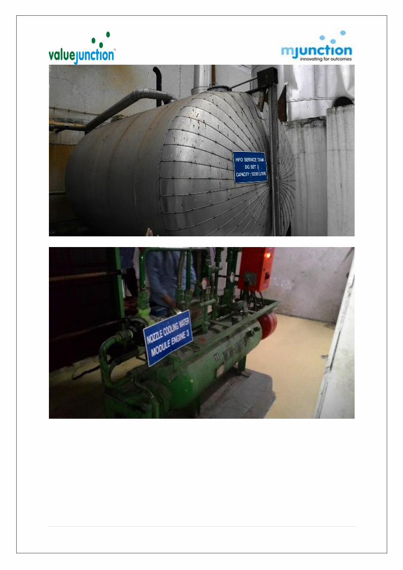
Pictures
The pictures shown below are indicative in nature. Interested bidders are advised to visit the site and
inspect the material, to satisfy them before participating in the sale event. Note: Video Recording of full load trial of all three DG Sets & total plant along with spares is available and interested customer may contact valujunction for same


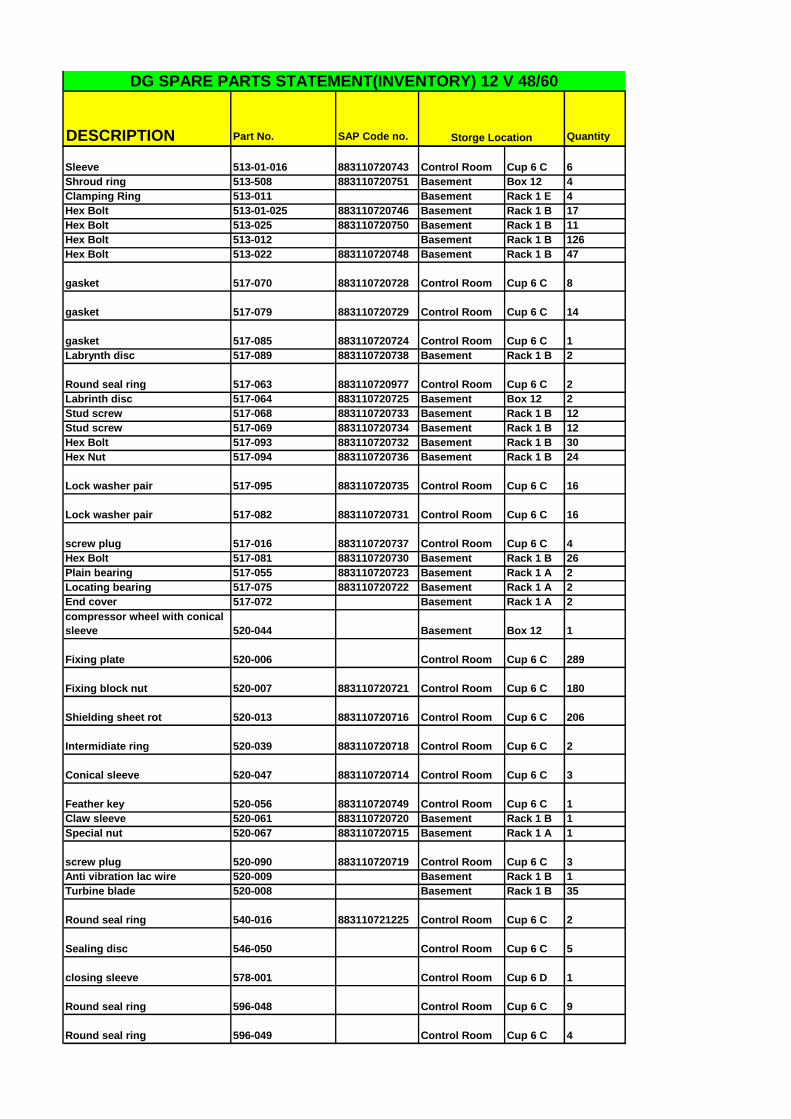
Annexure – 1
(Unused Spares)

DESCRIPTION Part No. SAP Code no. Quantity
CRANK CASETie rod 012-06-035 Basement Box 6 8
Round seal ring 012-06-036 883110720627 Control Room Cup 6 A 19
Round seal ring 012-06-037 Control Room Cup 6 A 10
O ring 012-06-038 Control Room Cup 6 A 7
Nut 012-06-039 Basement Box 12 3
Nut 012-06-020 Basement Rack 1 C 2
Nut 012-06-021 Basement Box 12 2
Stude Screw 012-06-030 Basement Rack 1 D 2
Round ring 012-06-032 883110720664 Control Room Cup 6 A 12
Nut 012-06-33 Basement Rack 1 E 2
Tie rod 012-06-019 Basement Box 5 2
CRANK SHAFT BEARINGBasement Rack 3 A 5
Basement Box 1 5
Basement Rack 3 A 5
Basement Box 1 5
Thrust bearing ring D=495 021-04-006 883110721821 Basement Box 1 3
Ledge 021-04-007 883110721822 Basement Box 1 2
Clamping Pin 021-04-008 883110721823 Basement Box 1 2
CONNECTING RODUpper connect rod bear 030-01-A 883110720628 Basement Rack 3 D 4
Lower connect rod bear 030-01-B 883110720629 Basement Rack 3 D 4
Nut 030-1-017 883110720632 Basement Rack 3 E 2
Nut 030-1-018 Basement Box 12 1
Piston Pin Bush 030-1-005 Basement Rack 3 B 2
Connecting rod head 030-01-003 883110720630 Basement Box 8 1
Connecting rod bolt 030-01-016 883110720631 Basement Rack 3 E 1
PISTONPiston Pin 034-01-002 883110720634 Basement Box 8 1
Retaining Ring 034-01-003 Basement Box 12 34
O Ring 034-01-511 Control Room Cup 6 E 12
Compression Ring (chrome
ceramic) only for new crown
1534 034-01-A 883110720638 Basement Rack 3 B 3
Compression Ring (unchromed)
1312 034-01-A 883110720639 Basement Rack 3 B 4
Compression Ring 1198 034-01-B 883110720640 Basement Rack 3 B 4
Compression Ring 1198 034-01-C 883110720641 Basement Rack 3 B 6
Oil scraper Ring 0234 034-01-D 883110720642 Basement Rack 3 B 4
Guide shoe complete with item
521-524 034-01-520 883110720636 Control Room Cup 6 A 1
Piston Skirt 034-01-503 Basement Box 8 1
Lock Ring 034-01-527 Control Room Cup 6 A 2
Clamping Pin 034-01-512 883110721443 Control Room Cup 6 A 6
Thrust Piece 034-01-514 883110720757 Control Room Cup 6 D 5
Nut 034-01-515 883110720758 Control Room Cup 6 D 5
Stud Screw 034-01-516 883110720635 Basement Rack 3 C 4
Pressure Sping 034-01-522 883110720637 Control Room Cup 6 A 2
CYLINDER LINER
DG SPARE PARTS STATEMENT(INVENTORY) 12 V 48/60
Lower bearing shell 021-04-003 883110720625
Upper bearing shell 021-04-001 883110720624
Storge Location

DESCRIPTION Part No. SAP Code no. Quantity
DG SPARE PARTS STATEMENT(INVENTORY) 12 V 48/60
Storge Location
Seal Ring(same as baffle screw) 050-04-015 883110720644 Control Room Cup 6 A 23
Seal Ring 050-04-029 883110720647 Basement Box 12 6
Fire Land Ring 050-04-040 883110720646 Basement Box 4 1
O Ring 050-04-041 883110720645 Control Room Cup 6 E 13
O Ring 050-04-032 Control Room Cup 6 A 151
O Ring 050-04-027 883110720990 Control Room Cup 6 E 65
CYLINDER HEAD
O Ring 055-04-022 883110720983 Control Room Cup 6 A 33
O Ring 055-04-027 883110720656 Control Room Cup 6 A 24
Valve Seat Ring(water cooled) 055-04-030 883110720650 Basement Rack 3 C 24
Valve Seat Ring(un- cooled) 055-04-030 Basement Rack 3 C 9
O Ring 055-04-031 Control Room Cup 6 A 24
Gasket 055-04-014 883110720649 Control Room Cup 6 A 1
Inlet Valve Guide 055-04-042 883110720651 Basement Rack 3 C 14
Round Seal Ring 055-04-043 883110720652 Control Room Cup 6 A 59
Stud Screw 055-04-047 883110720654 Control Room Cup 6 A 4
Hex. Nut 055-04-048 883110720655 Control Room Cup 6 A 2
O Ring 055-04-053 883110720658 Control Room Cup 6 E 16
O Ring 055-04-054 883110720659 Control Room Cup 6 E 12
O Ring 055-04-055 883110721445 Control Room Cup 6 C 8
O Ring 055-04-062 883110721444 Control Room Cup 6 C 9
O Ring 055-04-059/056 Control Room Cup 6 A 8
Gasket(EXH) 055-04-052 883110720657 Control Room Cup 6 A 12
cylinder cover bush 055-04-021 Control Room Cup 6 C 1
Stud for cylinder cover 055-04-045 883110720653 Basement Rack 3 B 6
CYLINDER HEAD COVER
Round Seal Ring 059-01-003 883110720661 Control Room Cup 6 E 8
Hex. Nut 059-01-010 Control Room Cup 6 A 4
Handle for roocker cover 059-01-005 Control Room Cup 6 A 4
CASING FREE END SIDE
Round Seal Ring 072-04-006 883110720662 Control Room Cup 6 E 12
RELIFE VALVE
O ring seal 073-02-006 883110720663 Control Room Cup 6 A 6
CRANK CASE COVER
Seal ring 073-03-018 883110720752 Control Room Cup 6 E 10

DESCRIPTION Part No. SAP Code no. Quantity
DG SPARE PARTS STATEMENT(INVENTORY) 12 V 48/60
Storge Location
Gasket 073-03-021 883110720665 Control Room Cup 6 C 14
CAM SHAFT CASING
CAM SHAFT BEARINGUpper CAM Shaft Bearing 102-05-A Basement Box 2 29
Lower CAM Shaft Bearing 102-05-B Basement Box 2 29
Bearing Body 102-07-001 Basement Rack 1 C 1
CONTROL LEVER WITH
BEARING
Washer 111-04-051 Control Room Cup 6 A 1
Round Seal Ring 111-04-010 883110720668 Control Room Cup 6 A 14
Thrust Piece 111-04-017 883110720669 Control Room Cup 6 A 5
Thrust Piece 111-04-019 Control Room Cup 6 A 4
Ball Cup 111-04-020 Control Room Cup 6 A 1
Circlip 111-04-021 883110720670 Control Room Cup 6 A 6
Ball Cup 111-04-023 Control Room Cup 6 A 1
Circlip 111-04-024 Control Room Cup 6 A 2
Thrust Piece 111-04-043 883110720667 Control Room Cup 6 A 1
Thrust Piece 111-04-044 Control Room Cup 6 A 1
INLET & EXHAUST
ROCKER ARM
Rocker Arm ,1,2IN&Out) 112.09.002 Basement Rack 1 D 1
Push Rod 112-08-001 Basement Box 6 2
Bearing Bush 112-09-003 Basement Rack 1 E 4
Roller 112-09-008 Basement Rack 1 C 1
INLET VALVEValve Cone 113-03-003 883110720671 Basement Box 4 13
Valve Rotating Device 113-03-014 883110720672 Basement Rack 1 C 16
EXHAUST VALVE
O ring 114-03-003 883110720678 Control Room Cup 6 A 34
Exhaust Valve Cone 114-03-006 883110720673 Basement Box 4 2
Axil Bearing SKF 51118 (L) 883110721584 Control Room Cup 6 C 9
Round Seal Ring 114-03-019 883110720677 Control Room Cup 6 E 40
Washer 114-03-023 883110720679 Basement Rack 3 B 19
Valve Guide 114-03-512 883110720675 Basement Rack 3 C 15
SS Braided hose (Local
cont.) 883110422144 Control Room Cup 6 D 13
Pressure reducing valve 125-98-589 883110720986 Control Room Cup 8 D 2
MANOEURING
EQUIPMENT

DESCRIPTION Part No. SAP Code no. Quantity
DG SPARE PARTS STATEMENT(INVENTORY) 12 V 48/60
Storge Location
Pressure Regulating Valve 125-98-138 Control Room Cup 8 D 3
Profile gasket 125-98-812 883110720370 Control Room Cup 8 D 24
Non return Valve 125-98-469 Control Room Cup 8 E 2
End switch 125-98-745 Control Room Cup 8 D 1
3/2 W ay Solenoid valve 125-98-573 883110720985 Control Room Cup 8 D 1
Throttle non return valve 125-98-590 883110720371 Control Room Cup 8 E 3
3/2 W ay valve 125-98-596 883110720358 Control Room Cup 8 E 3
Set of Wear Parts 125-99-317 883110720369 Control Room Cup 8 D 5
3/2 W ay Solenoid valve 125-98-371 883110720984 Control Room Cup 8 D 1
3/2 W ay Solenoid v/v M329/2
with plate "Emergency stop" 125-98-329
883110720365/
883110721837 Basement Box 1 1
3/2 W ay Solenoid v/v M329/1
with plate "Emergency start" 125-98-329 883110721825 Basement Box 1 1
Set of Wear Parts 125-99-329 883110720364 Control Room Cup 8 D 3
Set of Wear Parts 125-99-388 883110722174 Control Room Cup 8 D 3
Filter element 125-99-462 883110721456 Control Room Cup 8 A 2
Round seal ring 125-99-462 Z/P7 883110721457 Control Room Cup 8 A 1
Round seal ring 125-99-462 Z/P5 883110721458 Control Room Cup 8 A 1
Round seal ring 125-99-462 Z/P8 883110721459 Control Room Cup 8 A 1
Speed setting motor
140-16-NP1(1SV
1010) 883110720975 Control Room Cup 8 D 2
Rod end bearing(RH) 140-16-030 883110720882 Control Room Cup 6 D 4
Rod end bearing(LH) 140-16-031 883110720883 Control Room Cup 6 D 4
Set of gasket (Booster) 140-17-075-01 Basement Rack 3 A 1
Control piston 160-01-006 Control Room Cup 6 A 2
Set OF Gasket 160-01-007 883110720989 Control Room Cup 6 A 10
Valve Cone 161-01-003 883110720683 Control Room Cup 6 A 1
Pressure spring 161-01-004 Basement Rack 3 B 6
Piston 161-01-005 883110720680 Control Room Cup 6 A 1
Set OF Gasket 161-01-006 883110720681 Control Room Cup 6 A 4
GOVERNOR DRIVE
STARTING AIR PILOT
VALVE
STARTING VALVE

DESCRIPTION Part No. SAP Code no. Quantity
DG SPARE PARTS STATEMENT(INVENTORY) 12 V 48/60
Storge Location
Set OF Gasket 161-01-007 883110720682 Control Room Cup 6 A 4
O Ring (221-1-014) 161-01-012 Control Room Cup 6 A 42
Valve seat 162-02-003 Basement Box 4 2
Plunger 162-02-004 Control Room Cup 8 E 2
Safty valve 162-02-005 Control Room Cup 8 E 3
Seal ring 162-02-006 Control Room Cup 8 E 4
Pressure Spring 162-02-008 Control Room Cup 8 E 6
Set OF Gasket 162-02-009 Control Room Cup 8 E 9
Seal ring 162-02-011 Control Room Cup 8 E 4
Valve seat 162-02-014 Control Room Cup 8 E 4
Vending cone 162-02-015 Control Room Cup 8 E 4
Piston 162-02-016 Control Room Cup 8 E 4
Set OF Gasket 162-02-017 Control Room Cup 8 E 9
Lock nut 162-02-018 Control Room Cup 8 E 4
Closing cap 162-02-019 Control Room Cup 8 E 4
Ball cock 162-02-032 Control Room Cup 8 E 2
Seal ring 162-02-033 Control Room Cup 8 E 5
Hex. Bolt 200-01-020 Control Room Cup 6 B 12
Hex. Bolt 200-01-027 Control Room Cup 6 B 12
Round seal ring 200-01-031 883110721036 Control Room Cup 6 B 49
O Ring 200-01-032 Control Room Cup 6 B 1
O Ring 200-01-050 883110720689 Control Room Cup 6 B 4
Fitting Disk 200-01-053 Control Room Cup 6 B 4
Control Sleave 200-01-035 Control Room Cup 6 B 1
Ball 200-01-014( J ) Control Room Cup 6 B 18
Spring Plate 200-01-015 (L) 883110721446 Control Room Cup 6 B 5
Pressure Spring 200-01- M (16) 883110720686 Control Room Cup 6 B 44
Sleave 200-01-019 883110721449 Basement Rack 1 C 2
Clamping Pin 200-01- S (21) 883110721450 Control Room Cup 6 B 6
Baffle Screw 200-01-G 883110720685 Basement Rack 1 C 73
Pressure Spring 200-01-039 Basement Rack 1 C 1
Hex. Bolt 200-01-041 Control Room Cup 6 B 6
MAIN STARTING VALVE
FUEL INJECTION PUMP
DESCRIPTION Part No. SAP Code no. Quantity
DG SPARE PARTS STATEMENT(INVENTORY) 12 V 48/60
Storge Location
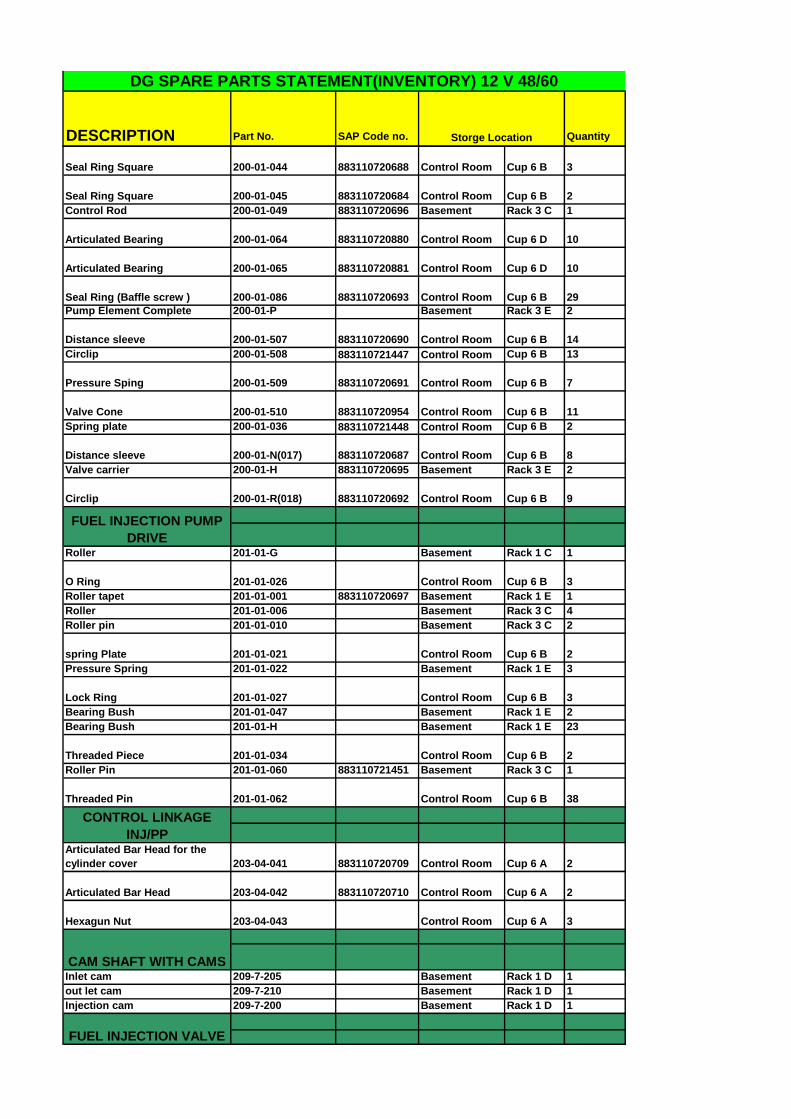
Seal Ring Square 200-01-044 883110720688 Control Room Cup 6 B 3
Seal Ring Square 200-01-045 883110720684 Control Room Cup 6 B 2
Control Rod 200-01-049 883110720696 Basement Rack 3 C 1
Articulated Bearing 200-01-064 883110720880 Control Room Cup 6 D 10
Articulated Bearing 200-01-065 883110720881 Control Room Cup 6 D 10
Seal Ring (Baffle screw ) 200-01-086 883110720693 Control Room Cup 6 B 29
Pump Element Complete 200-01-P Basement Rack 3 E 2
Distance sleeve 200-01-507 883110720690 Control Room Cup 6 B 14
Circlip 200-01-508 883110721447 Control Room Cup 6 B 13
Pressure Sping 200-01-509 883110720691 Control Room Cup 6 B 7
Valve Cone 200-01-510 883110720954 Control Room Cup 6 B 11
Spring plate 200-01-036 883110721448 Control Room Cup 6 B 2
Distance sleeve 200-01-N(017) 883110720687 Control Room Cup 6 B 8
Valve carrier 200-01-H 883110720695 Basement Rack 3 E 2
Circlip 200-01-R(018) 883110720692 Control Room Cup 6 B 9
Roller 201-01-G Basement Rack 1 C 1
O Ring 201-01-026 Control Room Cup 6 B 3
Roller tapet 201-01-001 883110720697 Basement Rack 1 E 1
Roller 201-01-006 Basement Rack 3 C 4
Roller pin 201-01-010 Basement Rack 3 C 2
spring Plate 201-01-021 Control Room Cup 6 B 2
Pressure Spring 201-01-022 Basement Rack 1 E 3
Lock Ring 201-01-027 Control Room Cup 6 B 3
Bearing Bush 201-01-047 Basement Rack 1 E 2
Bearing Bush 201-01-H Basement Rack 1 E 23
Threaded Piece 201-01-034 Control Room Cup 6 B 2
Roller Pin 201-01-060 883110721451 Basement Rack 3 C 1
Threaded Pin 201-01-062 Control Room Cup 6 B 38
Articulated Bar Head for the
cylinder cover 203-04-041 883110720709 Control Room Cup 6 A 2
Articulated Bar Head 203-04-042 883110720710 Control Room Cup 6 A 2
Hexagun Nut 203-04-043 Control Room Cup 6 A 3
Inlet cam 209-7-205 Basement Rack 1 D 1
out let cam 209-7-210 Basement Rack 1 D 1
Injection cam 209-7-200 Basement Rack 1 D 1
FUEL INJECTION PUMP
DRIVE
CONTROL LINKAGE
INJ/PP
CAM SHAFT WITH CAMS
FUEL INJECTION VALVE

DESCRIPTION Part No. SAP Code no. Quantity
DG SPARE PARTS STATEMENT(INVENTORY) 12 V 48/60
Storge Location
Sprng plate 221-01-010 883110720957 Control Room Cup 6 B 7
Pressure Spring 221-01-011 883110720958 Control Room Cup 6 B 4
Thrust Piece 221-01-012 883110720959 Control Room Cup 6 B 7
O RING (161-1-012) 221-01-014 883110720698 Control Room Cup 6 B 94
Clamping Pin 221-01-015 883110720960 Control Room Cup 6 B 5
Injection Nozzle 221-02-K 883110720699 Basement Rack 3 C 7
Injection valve 221-01-K Basement Rack 1 A 3
Axial compensator 280-14-007 883110720874 Basement Box 9 1
Pipe Coupling 280-14-008 883110720876 Basement Rack 3 A 13
O RING 280-14-010 Control Room Cup 6 C 19
Axial compensator 289-11-015 Basement Box 3 4
Axial compensator 289-11-014 Basement Box 9 2
Cuick coupling 289-11-017 Basement Box 9 2
Inspection glass 302-02-012 Control Room Cup 6 A 7
Alarm unit 302-02-019 Control Room Cup 8 A 2
Oil pump for valve seat
lubrication 302-17-001 883110721460 Basement Box 1 1
Block distributor 302-17-008 883110721461 Basement Box 1 1
Measuring riser with e- module
(OMD) 413.X1.NP1 883110721442 Control Room Cup 8 D 1
Filter element 413-A-10790 883110720979 Control Room Cup 6 D 3
Set of Wear Parts 413-A-10001-VP 883110720972 Control Room Cup 6 D 3
Air filter 413-A-10002 883110720971 Control Room Cup 6 D 8
Scavang air filter(413-06-015) 413-A-10042 883110720372 Control Room Cup 6 D 4
Threaded socket 419-01-D 883110720961 Basement Rack 3 C 5
Connection socket 419-01-001 883110720965 Basement Rack 3 C 2
Sleeve 419-01-002 883110720701 Control Room Cup 6 D 6
Cylindrical screw 419-01-003 883110720964 Basement Rack 3 C 6
Seal ring 419-01-006 883110720962 Control Room Cup 6 D 35
Indicator pipe 419-01-007 Basement Rack 3 B 1
Seal ring 419-01-011 883110720963 Control Room Cup 6 D 9
Indicator valve 419-01-012 883110720700 Basement Box 4 11
CYLINDER LUBRICATOR
LUBRICATION OIL PUMP
FOR VALVE SEAT
LUBRICATION
OIL MIST DETECTOR
UNIT
INDICATING DEVICE
PIPING FOR TURBO
CHARGER
CHARGE AIR PIPE
EXHAUST PIPE

DESCRIPTION Part No. SAP Code no. Quantity
DG SPARE PARTS STATEMENT(INVENTORY) 12 V 48/60
Storge Location
Pressure reducing valve 430-13-145 Control Room Cup 8 E 1
Flame breaker 432-07-007 883110721037 Basement Rack 1 C 2
Cylindrical screw 432-07-016 883110721035 Basement Rack 1 C 8
Cylindrical screw 432-07-014 883110721038 Basement Rack 1 C 8
Round seal ring 432-07-011 883110720702 Control Room Cup 6 B 20
Round seal ring(161-01-012) 434-01-006 883110720703 Control Room Cup 6 B 14
O ring seal 434-01-008 Control Room Cup 6 B 69
Nut 434-01-016 Control Room Cup 6 E 48
Jacketed injection pipe 434-01-L 883110721824 Basement Box 1 4
Circlip 434-01-019 Control Room Cup 6 B 48
O ring seal 434-01-022 883110720760 Control Room Cup 6 B 34
O ring seal 434-15-113 883110720966 Control Room Cup 6 B 2
O ring seal 434-15-120 Control Room Cup 6 B 16
O ring seal 434-15-116 883110720705 Control Room Cup 6 B 46
Hollow screw 434-19-057 883110720967 Control Room Cup 6 B 1
seal ring 434-19-058 883110720968 Control Room Cup 6 B 6
seal ring 434-19-059 883110720969 Control Room Cup 6 B 6
O ring seal 434-19-062 883110721452 Control Room Cup 6 B 2
Pressure spring 434-20-011 Control Room Cup 6 B 3
Presure Spring 434-20-012 Control Room Cup 6 B 4
Seal Ring 434-20-016 883110721453 Control Room Cup 6 B 4
Gasket 434-20-018 883110720706 Control Room Cup 6 B 1
Piston 434-20-020 883110720708 Basement Rack 1 C 2
Pressure limiting valve 434-21-066 883110720727 Basement Rack 3 C 1
O Ring 434-21-066-14 Control Room Cup 6 B 2
Round seal ring 434-21-066-15 Control Room Cup 6 B 2
Feed pipe 440-18-024 Basement Rack 3 B 2
BUFFER PISTON
FUEL PIPES ON FREE
END
ROCKER ARM
LUBRICATION
STARTING AIR PIPE
FUEL INJECTION PIPE
FUEL PIPES
FUEL PIPES ON
COUPLING END

DESCRIPTION Part No. SAP Code no. Quantity
DG SPARE PARTS STATEMENT(INVENTORY) 12 V 48/60
Storge Location
O ring 447-23-067 Control Room Cup 6 C 34
O ring 490-009-010-16 Control Room Cup 6 C 4
Support ring 490-009-010-17 Control Room Cup 6 C 4
Support ring 490-009-010-19 Control Room Cup 6 C 4
O ring 490-009-010-18 Control Room Cup 6 C 4
Honing stone 490-NP-14 883110720711 Control Room Cup 6 C 124
O ring 490-009-346 22 883110721033 Control Room Cup 6 C 13
O ring 490-009-346-23 883110721034 Control Room Cup 6 C 12
O ring 490-009-346-19 883110721031 Control Room Cup 6 C 9
Round seal ring 490-009-346-20 883110721032 Control Room Cup 6 C 8
Bearing shell push-out tool 490-021-201 883110721240 Control Room Cup 6 C 1
Bearing shell push-out tool 490-021-202 883110721241 Control Room Cup 6 C 1
Centering templet 490-021-203 883110721238 Control Room Cup 6 C 1
Centering templet 490-021-204 883110721239 Control Room Cup 6 C 1
Ball guide adjustabale 490-050-136-28 Control Room Cup 6 C 3
Coupling shaft 490-212-15-300 Control Room Cup 6 C 1
Worm 490-212-15-001 Control Room Cup 6 C 1
Rack 490-212-40-20 Control Room Cup 6 C 2
COG Belt Disc 490-240-20-005 Control Room Cup 6 C 1
Wax coated paper 490-419-351-4 Control Room Cup 6 C 4
Grinding wheel 490-861-51-250 883110720713 Control Room Cup 6 C 5
Grinding wheel 490-861-60-626 883110720712 Control Room Cup 6 C 40
COG Belt (Drive Unit) 490- Control Room Cup 6 B 2
COG Belt 490-831-21-150 883110720970 Control Room Cup 6 C 4
Nozzel ring for TC 513-01-001
Nozzel ring for
TC Basement Box 12 2
Clamping Ring 513-010 883110720741 Basement Box 12 2
Lock washer 513-014 883110720747 Control Room Cup 6 C 10
Lock washer 513-01-015 883110720742 Control Room Cup 6 C 10
Lock washer 513-01-024 883110720745 Control Room Cup 6 C 16
COOLING WATER PIPES
HONING AND GRINDING
MACHINE
EXHAUST TURBO
CHARGER
DESCRIPTION Part No. SAP Code no. Quantity
DG SPARE PARTS STATEMENT(INVENTORY) 12 V 48/60
Storge Location
Sleeve 513-01-016 883110720743 Control Room Cup 6 C 6
Shroud ring 513-508 883110720751 Basement Box 12 4
Clamping Ring 513-011 Basement Rack 1 E 4
Hex Bolt 513-01-025 883110720746 Basement Rack 1 B 17
Hex Bolt 513-025 883110720750 Basement Rack 1 B 11
Hex Bolt 513-012 Basement Rack 1 B 126
Hex Bolt 513-022 883110720748 Basement Rack 1 B 47
gasket 517-070 883110720728 Control Room Cup 6 C 8
gasket 517-079 883110720729 Control Room Cup 6 C 14
gasket 517-085 883110720724 Control Room Cup 6 C 1
Labrynth disc 517-089 883110720738 Basement Rack 1 B 2
Round seal ring 517-063 883110720977 Control Room Cup 6 C 2
Labrinth disc 517-064 883110720725 Basement Box 12 2
Stud screw 517-068 883110720733 Basement Rack 1 B 12
Stud screw 517-069 883110720734 Basement Rack 1 B 12
Hex Bolt 517-093 883110720732 Basement Rack 1 B 30
Hex Nut 517-094 883110720736 Basement Rack 1 B 24
Lock washer pair 517-095 883110720735 Control Room Cup 6 C 16
Lock washer pair 517-082 883110720731 Control Room Cup 6 C 16
screw plug 517-016 883110720737 Control Room Cup 6 C 4
Hex Bolt 517-081 883110720730 Basement Rack 1 B 26
Plain bearing 517-055 883110720723 Basement Rack 1 A 2
Locating bearing 517-075 883110720722 Basement Rack 1 A 2
End cover 517-072 Basement Rack 1 A 2
compressor wheel with conical
sleeve 520-044 Basement Box 12 1
Fixing plate 520-006 Control Room Cup 6 C 289
Fixing block nut 520-007 883110720721 Control Room Cup 6 C 180
Shielding sheet rot 520-013 883110720716 Control Room Cup 6 C 206
Intermidiate ring 520-039 883110720718 Control Room Cup 6 C 2
Conical sleeve 520-047 883110720714 Control Room Cup 6 C 3
Feather key 520-056 883110720749 Control Room Cup 6 C 1
Claw sleeve 520-061 883110720720 Basement Rack 1 B 1
Special nut 520-067 883110720715 Basement Rack 1 A 1
screw plug 520-090 883110720719 Control Room Cup 6 C 3
Anti vibration lac wire 520-009 Basement Rack 1 B 1
Turbine blade 520-008 Basement Rack 1 B 35
Round seal ring 540-016 883110721225 Control Room Cup 6 C 2
Sealing disc 546-050 Control Room Cup 6 C 5
closing sleeve 578-001 Control Room Cup 6 D 1
Round seal ring 596-048 Control Room Cup 6 C 9
Round seal ring 596-049 Control Room Cup 6 C 4
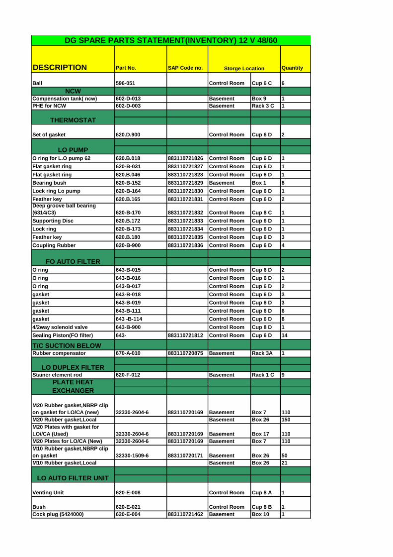
DESCRIPTION Part No. SAP Code no. Quantity
DG SPARE PARTS STATEMENT(INVENTORY) 12 V 48/60
Storge Location
Ball 596-051 Control Room Cup 6 C 6
NCWCompensation tank( ncw) 602-D-013 Basement Box 9 1
PHE for NCW 602-D-003 Basement Rack 3 C 1
Set of gasket 620.D.900 Control Room Cup 6 D 2
O ring for L.O pump 62 620.B.018 883110721826 Control Room Cup 6 D 1
Flat gasket ring 620-B-031 883110721827 Control Room Cup 6 D 1
Flat gasket ring 620.B.046 883110721828 Control Room Cup 6 D 1
Bearing bush 620-B-152 883110721829 Basement Box 1 8
Lock ring Lo pump 620-B-164 883110721830 Control Room Cup 6 D 1
Feather key 620.B.165 883110721831 Control Room Cup 6 D 2
Deep groove ball bearing
(6314/C3) 620-B-170 883110721832 Control Room Cup 8 C 1
Supporting Disc 620.B.172 883110721833 Control Room Cup 6 D 1
Lock ring 620-B-173 883110721834 Control Room Cup 6 D 1
Feather key 620.B.180 883110721835 Control Room Cup 6 D 3
Coupling Rubber 620-B-900 883110721836 Control Room Cup 6 D 4
O ring 643-B-015 Control Room Cup 6 D 2
O ring 643-B-016 Control Room Cup 6 D 1
O ring 643-B-017 Control Room Cup 6 D 2
gasket 643-B-018 Control Room Cup 6 D 3
gasket 643-B-019 Control Room Cup 6 D 3
gasket 643-B-111 Control Room Cup 6 D 6
gasket 643 -B-114 Control Room Cup 6 D 8
4/2way solenoid valve 643-B-900 Control Room Cup 8 D 1
Sealing Piston(FO filter) 643- 883110721812 Control Room Cup 6 D 14
T/C SUCTION BELOWRubber compensator 670-A-010 883110720875 Basement Rack 3A 1
Stainer element rod 620-F-012 Basement Rack 1 C 9
M20 Rubber gasket,NBRP clip
on gasket for LO/CA (new) 32330-2604-6 883110720169 Basement Box 7 110
M20 Rubber gasket,Local Basement Box 26 150
M20 Plates with gasket for
LO//CA (Used) 32330-2604-6 883110720169 Basement Box 17 110
M20 Plates for LO/CA (New) 32330-2604-6 883110720169 Basement Box 7 110
M10 Rubber gasket,NBRP clip
on gasket 32330-1509-6 883110720171 Basement Box 26 50
M10 Rubber gasket,Local Basement Box 26 21
Venting Unit 620-E-008 Control Room Cup 8 A 1
Bush 620-E-021 Control Room Cup 8 B 1
Cock plug (5424000) 620-E-004 883110721462 Basement Box 10 1
THERMOSTAT
LO PUMP
FO AUTO FILTER
LO DUPLEX FILTER
PLATE HEAT
EXCHANGER
LO AUTO FILTER UNIT

DESCRIPTION Part No. SAP Code no. Quantity
DG SPARE PARTS STATEMENT(INVENTORY) 12 V 48/60
Storge Location
Stainer element 620-E-006 Basement Rack 1 D 152
Cam disc (5134200) 620-E-023 883110721463 Control Room Cup 8 B 1
O Ring 620-E-036 Control Room Cup 8 B 4
O Ring 620-E-039 Control Room Cup 8 B 5
Scraper 620-E-043 Control Room Cup 8 B 4
Groved-ring 620-E-045 Control Room Cup 8 B 4
O-ring 620-E-050 Control Room Cup 8 B 7
5/2 way valve 620-E-060 Control Room Cup 8 B 2
Magnet coil 620-E-060-01 Control Room Cup 8 A 1
O-ring (3030063) 620-E-038 883110721464 Control Room Cup 8 B 8
Safty Valve 620-E-071 Control Room Cup 8 B 1
Differential Pressure switch 620-E-073 Control Room Cup 8 B 1
Pressure Spring 620-E-103 Control Room Cup 8 B 1
Shaft nut (5002790) 620-E-104 883110721467 Control Room Cup 8 B 1
Straight Pin (2300123) 620-E-108 883110721468 Control Room Cup 8 B 1
Feather key (2400109) 620-E-111 883110721469 Control Room Cup 8 B 1
Traurc Inverted V ring (3542193) 620-E-049 883110721470 Control Room Cup 8 B 3
O ring 620-E-032 Control Room Cup 8 B 10
O ring 620-E-041 Control Room Cup 8 B 3
Sealing piston 620-E-044 Control Room Cup 8 B 1
O ring (3041058) 620-E-046 883110721465 Control Room Cup 8 B 4
O ring (3050256) 620-E-047 883110721466 Control Room Cup 8 B 5
Set of sealing 620-E-180 Control Room Cup 8 E 3
Cylindrical roller bearing 620-E-058 883110721039 Control Room Cup 8 E 1
O-ring 620-C-012 Control Room Cup 8 B 4
O-ring 620-C-016 Control Room Cup 8 B 2
O-ring 620-C-020 Control Room Cup 8 B 2
O-ring 620-C-025 Control Room Cup 8 B 2
O-ring 620-C-061 Control Room Cup 8 B 4
Valve spring 620-C-211 Control Room Cup 8 B 1
Valve cone 620-C-008 Control Room Cup 6 D 1

DESCRIPTION Part No. SAP Code no. Quantity
DG SPARE PARTS STATEMENT(INVENTORY) 12 V 48/60
Storge Location
Spring 620-C-229 Control Room Cup 6 D 1
Angle Ball Cock (2560063) 883110721816 Control Room Cup 6 D 2
PCB for diode monitor Control Room Cup 8 B 2
Motorize valve 643-D-04-050 Control Room Cup 8 D 1
Single type Thermo couple ,
EXH 409-A-001 Control Room Cup 8 E 10
Seal ring 006 Control Room Cup 8 D 10
Rotor 400-01-002 Control Room Cup 8 A 1
Speed Pick Up 400-05-001 Control Room Cup 8 A 6
Plug 400-05-002 Control Room Cup 8 A 5
Elect.Bulb 125-X1-102 883110720363 Control Room Cup 8 B 32
Magnet 110/110V DC Control Room Cup 8 D 2
Under Voltage protection 3AX-1103-2E Control Room Cup 8 A 1
Time relay DC 24 V AI 933N.0082 Control Room Cup 8 A 1
Speed control device(on/off) 994-008/ss1002 Control Room Cup 8 A 2
Speed control device(over
speed) 994-010/1SSZ1002 Control Room Cup 8 D 3
Speed control device(over
speed) 994-012-2SSZ1002 Control Room Cup 8 E 1
Rpm indicator 994-021/SI1004 Control Room Cup 8 D 3
Speed Pick Up (T/C) 994-020/1SE1004 Control Room Cup 8 A 4
Elec. Speed indicator 994-002/1SI1000 Control Room Cup 8 D 2
Rectifier Module Control Room Cup 8 A 1
Synchronizer indictaor Control Room Cup 8 B 1
Frequency to current 994-005-/St1000 Control Room Cup 8 D 1
Frequency to current 994-022-/St1004 Control Room Cup 8 D 4
Trip Solenoid 994-023-/1SZ-1010 Control Room Cup 8 A 1
Motor contactor 991-009-B123022 Control Room Cup 8 A 1
Motor circuite breaker 602-d-f1 Control Room Cup 8 A 1
Pressure transmitter 994-343-pt7180 Control Room Cup 8 A 2
Pressure trnsmitter 994-346-pt7400 Control Room Cup 8 A 1
Pressure trnsducer 994-319-pt6180 Control Room Cup 8 A 1
Pressure trnsducer 994-022/pt110 Control Room Cup 8 A 1
ELECTRICALS SPARES

DESCRIPTION Part No. SAP Code no. Quantity
DG SPARE PARTS STATEMENT(INVENTORY) 12 V 48/60
Storge Location
Spare contactor star/delta Control Room Cup 8 C 1
Alternator bearing pump Control Room Cup 8 C 1
Flow switch for ABOC (GEN) Control Room Cup 8 A 1
Resistance thermometer, PT
100(new type) 994-085/2te2580 Control Room Cup 8 B 6
Operation panel 991-c-025 Control Room Cup 8 B 1
Loauto filter cards Control Room Cup 8 B 2
Solenoid valve(DE F) 620-C-100 Control Room Cup 8 D 2
Indicating instrument 926-961 Control Room Cup 8 D 2
Heating paste 413-A-NP3 883110720367 Control Room Cup 8 D 1
Temperature sensor 408-A-001 Control Room Cup 8 C 1
Temp. sensor PT 100(Local) 883110721203 Control Room Cup 8 E 6
EFF1,3KW,2820
RPM,100L,B3,MOTOR JCW HEATER 883110720944 Basement Basement 1
Mech. Seal for Booster p/p
ACG045K5NTBT,Si
ze 25mm,Type-
SB/S-43/0250/M1 883110720622 Control Room Cup 12 D 6
Mech. Seal for cooling water
p/p
Allweller
pump,Model no.
160/011/70.Type-
ERS/B/0300 883110720403 Control Room Cup 12 D 2
Allweiler p/p for JCW/CA
Type:NI80-
160/01/170U3.1D-
W19-42/350 Control Room Cup 12 D 2
Mech. Seal for sep. feed p/p
Tushco Model 338-
248,Type-SB/S-
43/0380 883110720623 Control Room Cup 12 D 6
Bearing for feed p/p 6305 2Z Control Room Cup 12 D
Mech. Seal for NCW p/p
Grunfoes
Monoblock,Size 12
mm,Type-
GSCU/0122 883110720621 Control Room Cup 12 D 3
Mech. Seal for Preheating
p/p
Grundfoes LP65-
125/128 883110720886 Control Room Cup 12 D 1
Mech. Seal for Preheating
priming p/p NB 32-160 883110721804 Control Room Cup 12 D 2
Sight Glass 0001-0028-830 883110721068 Control Room Cup 7 E 1
Gasket 0004-5056-740 883110721070 Control Room Cup 7 D 30
Gasket 0004-2199-750 883110721069 Control Room Cup 7 E 12
Gasket 0004-1657-770 883110721017 Control Room Cup 7 E 15
Gasket 0004-1658-770 883110721020 Control Room Cup 7 E 14
HFO & LO SEPERATOR
PUMP SERVICE KIT
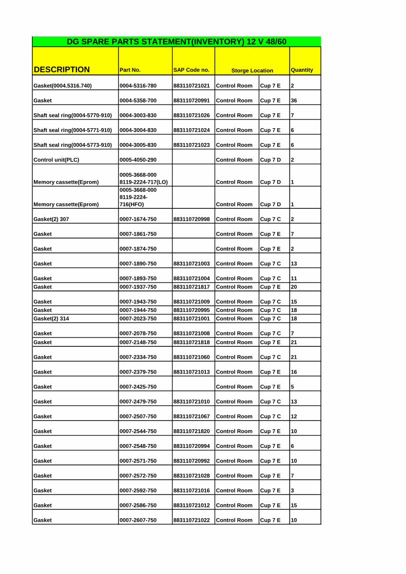
DESCRIPTION Part No. SAP Code no. Quantity
DG SPARE PARTS STATEMENT(INVENTORY) 12 V 48/60
Storge Location
Gasket(0004.5316.740) 0004-5316-780 883110721021 Control Room Cup 7 E 2
Gasket 0004-5358-700 883110720991 Control Room Cup 7 E 36
Shaft seal ring(0004-5770-910) 0004-3003-830 883110721026 Control Room Cup 7 E 7
Shaft seal ring(0004-5771-910) 0004-3004-830 883110721024 Control Room Cup 7 E 6
Shaft seal ring(0004-5773-910) 0004-3005-830 883110721023 Control Room Cup 7 E 6
Control unit(PLC) 0005-4050-290 Control Room Cup 7 D 2
Memory cassette(Eprom)
0005-3668-000
8119-2224-717(LO) Control Room Cup 7 D 1
Memory cassette(Eprom)
0005-3668-000
8119-2224-
716(HFO) Control Room Cup 7 D 1
Gasket(2) 307 0007-1674-750 883110720998 Control Room Cup 7 C 2
Gasket 0007-1861-750 Control Room Cup 7 E 7
Gasket 0007-1874-750 Control Room Cup 7 E 2
Gasket 0007-1890-750 883110721003 Control Room Cup 7 C 13
Gasket 0007-1893-750 883110721004 Control Room Cup 7 C 11
Gasket 0007-1937-750 883110721817 Control Room Cup 7 E 20
Gasket 0007-1943-750 883110721009 Control Room Cup 7 C 15
Gasket 0007-1944-750 883110720995 Control Room Cup 7 C 18
Gasket(2) 314 0007-2023-750 883110721001 Control Room Cup 7 C 18
Gasket 0007-2078-750 883110721008 Control Room Cup 7 C 7
Gasket 0007-2148-750 883110721818 Control Room Cup 7 E 21
Gasket 0007-2334-750 883110721060 Control Room Cup 7 C 21
Gasket 0007-2379-750 883110721013 Control Room Cup 7 E 16
Gasket 0007-2425-750 Control Room Cup 7 E 5
Gasket 0007-2479-750 883110721010 Control Room Cup 7 C 13
Gasket 0007-2507-750 883110721067 Control Room Cup 7 C 12
Gasket 0007-2544-750 883110721820 Control Room Cup 7 E 10
Gasket 0007-2548-750 883110720994 Control Room Cup 7 E 6
Gasket 0007-2571-750 883110720992 Control Room Cup 7 E 10
Gasket 0007-2572-750 883110721028 Control Room Cup 7 E 7
Gasket 0007-2592-750 883110721016 Control Room Cup 7 E 3
Gasket 0007-2586-750 883110721012 Control Room Cup 7 E 15
Gasket 0007-2607-750 883110721022 Control Room Cup 7 E 10

DESCRIPTION Part No. SAP Code no. Quantity
DG SPARE PARTS STATEMENT(INVENTORY) 12 V 48/60
Storge Location
Gasket 0007-2608-750 883110721027 Control Room Cup 7 E 6
Gasket 0007-2631-750 883110721006 Control Room Cup 7 C 3
Gasket 0007-2636-750 883110721002 Control Room Cup 7 E 6
Gasket 0007-2641-750 883110721005 Control Room Cup 7 C 11
Gasket(Teflon) 0007-2849-910 883110720999 Basement Cup 7 C 2
Gasket(Teflon) 0007-2849-910 883110720999 Basement Rack 3 A 5
Gasket 0007-2925-750 883110721007 Control Room Cup 7 E 6
Gasket 0007-2940-750 883110721000 Control Room Cup 7 E 9
Gasket 0007-3032-750 883110720993 Control Room Cup 7 E 7
Clutch pully 2179-3370-020 Basement Rack 3 E 1
Bearing cover 2179-3375-000 Control Room Cup 7 E 1
Worm wheel shaft(H) 2179-3400-000 Control Room Cup 7 D 1
New 040 worm spindle(V) 2179-3420-000 Control Room Cup 7 D 1
Clutch shoe 0021-3051-000 883110720996 Control Room Cup 7 E 12
Protecting ring 0008-5508-050 883110721071 Control Room Cup 7 E 1
Protecting ring 0008-3008-050 Control Room Cup 7 E 1
Spring assembly compl. 0010-7220-000 883110721011 Control Room Cup 7 E 2
Chamber cover 2178-6642-030 Control Room Cup 7 E 1
Set of neck bearing spring 0006-4389-090 883110721018 Control Room Cup 7 E 1
Angular contact Ball beaing(V)
7306 BECBM SKF (L) 0011-7306-100 883110721585 Control Room Cup 7 E 8
Grooved Ball beaing (H&V)6211
P6 0011-6211-110 883110721015 Control Room Cup 7 E 7
Angular contact Ball beaing (H)
3208A B/T/H 0011-3208-470 883110721025 Control Room Cup 7 E 4
Spherical plain bearing, GE
80 ES 0011-8071-000 883110721588 Control Room Cup 7 E 2
Spring piston 0026-2225-110 883110721019 Control Room Cup 7 E 9
Rotex pneumatic V/V
(Displacement) 883110720860 Control Room Cup 7 E 1
Gasket 0018-4845-750 883110721819 Control Room Cup 7 E 12
Rotex Solenoid V/V(Sealing) 0018-8092-610 883110720861 Control Room Cup 7 D 1
Non return valve 0018-4273-600 Control Room Cup 7 D 1
Solinoid valve 0018-6226-600 Control Room Cup 7 D 1
Throttle valve(Rotex) 0018-1677-280 883110721535 Control Room Cup 7 D 4
Air filter(1/4inch-10bar) 0018-2535-600 883110721536 Control Room Cup 7 D 4
Water pressure reg. 0018-1741-000 Control Room Cup 7 D 1

DESCRIPTION Part No. SAP Code no. Quantity
DG SPARE PARTS STATEMENT(INVENTORY) 12 V 48/60
Storge Location
DTC 1set ponit PT-100 883110720762 Basement Cup 13 1
Diffuse plate 180 883110720763 Basement Cup 13 2
Electrode caps 883110720764 Basement Cup 13 2
Fuel pump 883110720765 Basement Cup 13 1
Mech.seal for fuel pump 883110720766 Basement Cup 13 2
Flame failure relay 883110720767 Basement Cup 13 1
Ignation Electrode 75X55 883110720770 Basement Cup 13 7
High Temp.Gland Washer
883110720771/
883110721748 Basement Cup 13 1
Photocell 883110720774 Basement Cup 13 1
RTD Sensor PT-100 883110720776 Basement Cup 13 1
Safety valve 1.5 883110720777 Basement Cup 13 1
PH make Solenoid valve F.O 883110720778 Basement Cup 13 3
Toughened Glass 883110720779 Basement Cup 13 3
No water switch MNLP UA 10 883110720780 Basement Cup 13 1
Pressure switch MAH-15 CB-10 883110720781 Basement Cup 13 2
F.O Brades pipe 3/8"X500mm 883110720782 Basement Cup 13 3
S.S.Brades pipe 3/8"X1000mm 883110720783 Basement Cup 13 3
Ignation Transformer 883110720784 Basement Cup 13 1
Blow down valve 1" 883110720785 Basement Cup 13 1
Filter Element (Duplex) 883110720786 Basement Cup 13 1
Backlite Gasket 883110720847 Basement Cup 13 5
Steam solenoid valve 1/4" 883110720848 Basement Cup 13 2
F.O Solenoid valve 1" 883110720849 Basement Cup 13 1
DTC 2set Point 883110720850 Basement Cup 13 1
Rubber Spider 883110720852 Basement Cup 13 2
Thermostat 0~200ºC 883110720853 Basement Cup 13 2
Pres. Guage, 0~42 Kg/Cm2,
Bottom connection 883110721744 Basement Cup 13 3
Pres. Guage, 0~42 Kg/Cm2,
Back connection 883110721745 Basement Cup 13 3
Bronze Valve DN 40 883110721746 Basement Cup 13 2
Bronze Valve DN 15 883110721747 Basement Cup 13 4
Fuel oil heater coil 883110721915 Basement Basement 1
HFO AUTO FILTER
UNIT, COMTECH
O-Ring ( Pos no.17) 2-261 883110721048 Basement Cup 13 9
O-Ring ( Pos no.18) 2-223 883110721049 Basement Cup 13 3
O-Ring ( Pos no.19) 2-118 883110721050 Basement Cup 13 6
O-Ring ( Pos no.15) 2-117 883110721051 Basement Cup 13 1
Mud Drain Throttle (
Pos no. 11) 4-25488 883110721052 Basement Cup 13 1
Valve seat/ valve Face (
Pos no.7) 4-25127 883110721053 Basement Cup 13 1
Diff.Pre. Indicator (Pos
no.51) 0.6~0.8 4.36.2 883110721054 Basement Cup 13 2
4/2way solenoid valve 643-B-900/ 2604928 883110721811 Basement Cup 13 4
Sleve disc for fuel filters 643-B-005/ 1830996 883110720626 Basement Cup 13 30
BOILER SPARES

DESCRIPTION Part No. SAP Code no. Quantity
DG SPARE PARTS STATEMENT(INVENTORY) 12 V 48/60
Storge Location
O-Ring 3031222 883110721814 Basement Cup 13 10
O-Ring 3034299 883110721815 Basement Cup 13 10
Support Body 6652259 883110721813 Basement Cup 13 1
HFO MANUAL FILTER
UNIT , COMTECH
O-Ring/Tech. Ring ( Pos no
.113) J-330-7-R-T 883110721055 Basement Cup 13 3
O-Ring ( Pos no.114) 2-231 883110721056 Basement Cup 13 6
CYLINDER L.O FILTER
UNIT , COMTECH
Filter Element /Disposable
Catridge ( Pos no.17) 883110721057 Basement Cup 13 12
O` Ring/ High Pre. Gasket (Pos
no: 6) 172x189x1.5 883110721058 Basement Cup 13 4
HFO P/P ROOM MANUAL
FILTER UNIT , COMTECH
O Ring/ Gasket (
Pos no. 7) 13d x 18 x 1.5 883110721059 Basement Cup 13 10
O Ring / High Pre. Gasket (Pos
no.5) 172dx189dx1.5 883110721058 Basement Cup 13 12
O Ring ( Pos no.15) 69d x 22 x 5.33 883110721061 Basement Cup 13 12
LO MANUAL FILTER
UNIT , COMTECH
O ring (Pos.No.6)
Art.-Nr.458
367.67x6.99 883110721062 Basement Cup 13 8
Filter element./ Socket Candle
(Pos. No. 12) 883110721063 Basement Rack 1 C 10
O-Ring/Gasket (Pos. No .24)
3420011
Best.Nr.2.02.036Art.-
Nr.375 240.67x5.33 883110721064 Basement Cup 13 7
Gasket (Pos.No.25)
3420011
Best.Nr.2.02.036Art.-
Nr.375 240.67x5.33 883110721064 Basement Cup 13 8
O-Ring (Pos.No.28)
3040133
Art.-Nr.378
260.07x5.33 883110721065 Basement Cup 13 7
Diff Press Indic (Pos.no32 )
0.9~1.2 4.36.2 883110721066 Basement Cup 13 2
Air Regulator 883110721211 Control Room Cup 7 C 1
Repair Kit for RCH306 883110721210 Control Room Cup 7 C 1
Item DescriptionQuantity Module MLFB
No
IMPORTED ELECTRICAL SPARE
HYDROLIC PUMP,
GEMINI

DESCRIPTION Part No. SAP Code no. Quantity
DG SPARE PARTS STATEMENT(INVENTORY) 12 V 48/60
Storge Location
1
Siemens make,
S7-400
Controller 1
S7-414-
2DP
6ES7
414-
2XK05-
0AB0
2
Siemens make,
S7-400 memory
card 1
2 MB
FEPROM
memory card
6ES7
952-
1KL00-
0AA0
3
Siemens make,
S7-300
Controller 1
S7-315-
2DP
6ES7
315-
2AH14-
0AB0
4
Siemens make,
S7-300 memory
card 1
2 MB Micro
Memory
Card
6ES7
953-
8LL20-
0AA0
5
Siemens make,
S7-400 power
supply 1 PS-405-4A
6ES7
405-
0DA02-
0AA0
6
Siemens make
S7-300, Profibus
Module IM153-1
1 IM-153-1
6ES7
153-
1AA03-
0XB0
7
Siemens make,
S7-300, Digital
Input module, 32
CH, 24V DC 1 DI-32
6ES7
321-
1BL00-
0AA0
8
Siemens make,
S7-300, Digital
Output module,
32 CH, 24V DC 1 DO-32
6ES7
322-
1BL00-
0AA0
9
Siemens make,
S7-300,
Analogue input
module, 8 CH,
Volt/Current 1 AI-8
6ES7
331-
7KF02-
0AB0
10
Siemens make,
S7-300,
Analogue Output
module, 8 CH,
Volt/Current1 AO-8
6ES7
332-
5HB01-
0AB0
11
Siemens make,
S7-300, Front
connectors for
DI/DO1
SPRING
TYPE
6ES7
392-
1BM01-
0AA0

DESCRIPTION Part No. SAP Code no. Quantity
DG SPARE PARTS STATEMENT(INVENTORY) 12 V 48/60
Storge Location
12
Siemens make,
S7-300, Front
connectors for
AI/AO 1
SPRING
TYPE
6ES7
392-
1BJ00-
0AA0
13
Siemens Make
Profibus DP
connector
5
With PG
Port
6ES79
72-
0BB42-
0XA0

Annexure – 2
(Reconditioned
Spares & Tools
available with the
Plant)

SR
NO TOOL NO DESCRIPTION QTY
1 OOO.262 Tommy Bar 8mm Dia Engine Room Tool Box 2 1
2 OOO.263 Tommy Bar 10mm Dia Engine Room Tool Box 2 1
3 OOO.264 Tommy Bar 12mm Dia Engine Room Tool Box 2 1
4 OOO.507 Tommy Bar 5mm Dia Engine Room Tool Box 2 1
5 OO9.068 Tommy Bar 6mm Dia Engine Room Tool Box 2 1
6 OO9.010 Hydraulic Tensioning Cylinder Engine Room Tool Box 2 2
7 OO9.022 Trunk Piston Tensioning Clylinder Engine Room Tool Box 2 1
8 OO9.028 Hydraulic Connector Engine Room Tool Box 2 2
9 OO9.062 Hydraulic Tensioning Cylinder Engine Room Tool Box 2 3
10 OO9.063 Hydraulic Tensioning Cylinder Engine Room Tool Box 2 3
11 OO9.072 Lifting tool ( Ratchet type) Engine Room Tool Box 2 1
12 OO9.072 Lifting tool (Hyd. Type) Engine Room Tool Box 2 1
13 OO9.079 Hydraulic Tensioning Cylinder Engine Room Tool Box 2 2
14 OO9.346 Hydraulic Tensioning Cylinder Engine Room Tool Box 2 5
15 OO9.338 High Pressure Pump 2000 Bar Engine Room Tool Box 3 1
16 O14.015 Stud remover Engine Room Tool Box 2 1
17 O20.046 Thrust piece Engine Room Tool Box 2 2
18 O21.089 Thrust piece Engine Room Tool Box 2 2
19 O21.195 Thrust piece Engine Room Tool Box 2 2
20 O30.206 Thrust piece Engine Room Tool Box 2 4
21 O55.100 Thrust piece Engine Room Tool Box 2 2
22 O55.125 Thrust piece Engine Room Tool Box 2 2
23 O55.126 Thrust piece Engine Room Tool Box 2 2
24 O55.127 Thrust piece Engine Room Tool Box 2 2
25 101.018 Thrust piece Engine Room Tool Box 2 4
26 O34.086 Piston Ring Pliers Engine Room Tool Box 2 1
27 OO2.165 Circlip Pliers Engine Room Tool Box 2 1
28 Wooden Block Engine Room Tool Box 2 4
29 Torque Wrench 50-210 Nm Engine Room Tool Box 2 2
30 Torque Wrench 140-560 Nm Engine Room Tool Box 2 2
31 Torque Wrench 750-2000 Nm Engine Room Tool Box 2 1
32 D3245 Torque Wrench 150-800 Nm (German) Engine Room Tool Box 2 1
33 Torque Wrench 475-1015 Nm Engine Room Tool Box 2 2
34 Torque Wrench DC-5A 100-500 Engine Room Tool Box 2 1
35 Pipe 2' long Engine Room Tool Box 2 2
36 O50.095 Liner Calibration Tool Engine Room Tool Box 2 1
37 Steel Scale (1mtr) Engine Room Tool Box 2 1
38 Vernier (1mtr) Engine Room Tool Box 2 1
39 36 Box with 1" female for tappet setting Engine Room Tool Box 2 1
40 36 Ring Spanner for tappet setting Engine Room Tool Box 3 2
41 Reducer 1" male X 3/4" female Control Room Spl Tool CB 1
42 Reducer 3/4" male X 1/2" female Control Room Spl Tool CB 2
43 1" female with 22mm Allen Head (Rocker arm) Engine Room Tool Box 2 1
44 Tool 030.235 Engine Room Tool Box 2 1
Portable Equipments for MAN DG Sets
STORAGE LOCATION
TOOLS CUPBOARD NO 2

SR NO PART NO. DESCRIPTION QTY
1 221.222 Injector nozzle test stand 48/60B; 51/60DF 1
2 113.242
Electric valve cone grinding machine without collet
chuck typ VKM 3.1 2
3 55.13
Mounting and turning device 40/50, 48/60B
51/60DF, 51/60G 2
4 113.251
Electrical valve seat turning machine maker VD4E,
AC 230 V (+/- 10%), 50-60 Hz 48/60B, 48/60CR1
SR NO TOOL NO DESCRIPTION QTY
1 Eye Bolt M10 Engine Room CB 3/ Rack 1 4
2 Eye Bolt M12 Engine Room CB 3/ Rack 1 4
3 Eye Bolt M16 Engine Room CB 3/ Rack 1 7
4 Eye Bolt M20 Engine Room CB 3/ Rack 1 3
5 Eye Bolt M24 Engine Room CB 3/ Rack 1 4
6 OOO-552 Ratchet type Tackle ( Chain Block) Engine Room CB 3/ Rack 1 1
7 O30-033 Carrier Engine Room CB 3/ Rack 1 1
8 030-237-9 Rod for dummy piston Engine Room CB 3/ Rack 1 1
9 O50-084 Installing & Removing tool (set of 6 nos) Engine Room CB 3/ Rack 1 1
10 O55-133 Injector pocket Cleaning Device Engine Room CB 3/ Rack 1 1
11 111-115 Connecting Shackle Engine Room CB 3/ Rack 1 3
12 113-131 Valve Spring Compression device Engine Room CB 3/ Rack 1 1
13 113-138 Valve seat mounting device Engine Room CB 3/ Rack 1 1
14 113-141 Installing & Removing tool v/v guide Engine Room CB 3/ Rack 1 1
15 114-030 Receptacles for Exh. cage pocket Engine Room CB 3/ Rack 1 2
16 114-031 Suspension nut Engine Room CB 3/ Rack 1 1
17 114-033 Holding device for valve cone Engine Room CB 3/ Rack 1 1
18 114-034-06 Extractor sleeve Engine Room CB 3/ Rack 1 1
19 114-034-13 Nut Engine Room CB 3/ Rack 1 1
20 161-014 Installing & Removing tool Engine Room CB 3/ Rack 1 1
21 200-062 Suspension device Engine Room CB 3/ Rack 1 1
22 201-009 Installing & Removing tool (Roller Tappet) Engine Room CB 3/ Rack 1 1
23 221-128 Extraction sleeve Engine Room CB 3/ Rack 1 1
24 221-129 Removing tool Engine Room CB 3/ Rack 1 1
25 434-029 Pin Wrench Engine Room CB 3/ Rack 1 1
26 201-006 Locking Tool for fuel pump Engine Room CB 3/ Rack 1 12
27 Injector sleeve removing device Engine Room CB 3/ Rack 1 1
28 Rubber Protection cover for Cylinder head Engine Room CB 3/ Rack 1 8
29 Rubber Protection Roll Engine Room CB 3/ Rack 1 1
SR NO TOOL NO DESCRIPTION QTY
30 OOO-333 Hook wrench Engine Room CB 3/ Rack 2 1
31 030-195 Holding device Engine Room CB 3/ Rack 2 4
( RACK 2)
STORAGE LOCATION
WORK SHOP
WORK SHOP
WORK SHOP
TOOLS CUPBOARD NO 3 ( RACK 1)
STORAGE LOCATION
WORK SHOP EQUIPMENTS
WORK SHOP
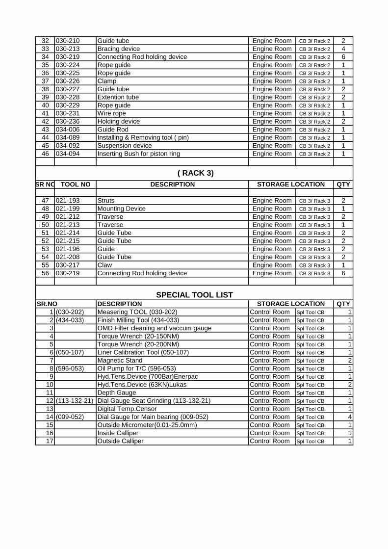
32 030-210 Guide tube Engine Room CB 3/ Rack 2 2
33 030-213 Bracing device Engine Room CB 3/ Rack 2 4
34 030-219 Connecting Rod holding device Engine Room CB 3/ Rack 2 6
35 030-224 Rope guide Engine Room CB 3/ Rack 2 1
36 030-225 Rope guide Engine Room CB 3/ Rack 2 1
37 030-226 Clamp Engine Room CB 3/ Rack 2 1
38 030-227 Guide tube Engine Room CB 3/ Rack 2 2
39 030-228 Extention tube Engine Room CB 3/ Rack 2 2
40 030-229 Rope guide Engine Room CB 3/ Rack 2 1
41 030-231 Wire rope Engine Room CB 3/ Rack 2 1
42 030-236 Holding device Engine Room CB 3/ Rack 2 2
43 034-006 Guide Rod Engine Room CB 3/ Rack 2 1
44 034-089 Installing & Removing tool ( pin) Engine Room CB 3/ Rack 2 1
45 034-092 Suspension device Engine Room CB 3/ Rack 2 1
46 034-094 Inserting Bush for piston ring Engine Room CB 3/ Rack 2 1
SR NO TOOL NO DESCRIPTION QTY
47 021-193 Struts Engine Room CB 3/ Rack 3 2
48 021-199 Mounting Device Engine Room CB 3/ Rack 3 1
49 021-212 Traverse Engine Room CB 3/ Rack 3 2
50 021-213 Traverse Engine Room CB 3/ Rack 3 1
51 021-214 Guide Tube Engine Room CB 3/ Rack 3 2
52 021-215 Guide Tube Engine Room CB 3/ Rack 3 2
53 021-196 Guide Engine Room CB 3/ Rack 3 2
54 021-208 Guide Tube Engine Room CB 3/ Rack 3 2
55 030-217 Claw Engine Room CB 3/ Rack 3 1
56 030-219 Connecting Rod holding device Engine Room CB 3/ Rack 3 6
SR.NO DESCRIPTION QTY
1 (030-202) Measering TOOL (030-202) Control Room Spl Tool CB 1
2 (434-033) Finish Milling Tool (434-033) Control Room Spl Tool CB 1
3 OMD Filter cleaning and vaccum gauge Control Room Spl Tool CB 1
4 Torque Wrench (20-150NM) Control Room Spl Tool CB 1
5 Torque Wrench (20-200NM) Control Room Spl Tool CB 1
6 (050-107) Liner Calibration Tool (050-107) Control Room Spl Tool CB 1
7 Magnetic Stand Control Room Spl Tool CB 2
8 (596-053) Oil Pump for T/C (596-053) Control Room Spl Tool CB 1
9 Hyd.Tens.Device (700Bar)Enerpac Control Room Spl Tool CB 1
10 Hyd.Tens.Device (63KN)Lukas Control Room Spl Tool CB 2
11 Depth Gauge Control Room Spl Tool CB 1
12 (113-132-21) Dial Gauge Seat Grinding (113-132-21) Control Room Spl Tool CB 1
13 Digital Temp.Censor Control Room Spl Tool CB 1
14 (009-052) Dial Gauge for Main bearing (009-052) Control Room Spl Tool CB 4
15 Outside Micrometer(0.01-25.0mm) Control Room Spl Tool CB 1
16 Inside Calliper Control Room Spl Tool CB 1
17 Outside Calliper Control Room Spl Tool CB 1
( RACK 3)
STORAGE LOCATION
SPECIAL TOOL LISTSTORAGE LOCATION

18 .000.454 Filler Gauge for Main Bearing (000.454) Control Room Spl Tool CB 1set
19 Filler Gauge 6 inch Control Room Spl Tool CB 3
20 Filler Gauge 1feet Control Room Spl Tool CB 1
21 Filler Gauge 1and1/2 Control Room Spl Tool CB 1
22 Air Gun Control Room Spl Tool CB 1
23 (030-302) Piston Centering Tool (030-302) Control Room Spl Tool CB 1
24 Needle File Set Control Room Spl Tool CB 1
25 Diamond File Control Room Spl Tool CB 2
26 (200-068) FIP Setting Tool (200-068) Control Room Spl Tool CB 1
27 NCW Air Tank Measuring Tool Control Room Spl Tool CB 1
28 (008-171) Deflection Gauge (008-171) Control Room Spl Tool CB 1
29 Extention Flexible Pipe Control Room Spl Tool CB 2
30 Pre. Gauge for Honing Tool Air Hose PRV Control Room Spl Tool CB 1
31 Dissolved Solid Tester Control Room Spl Tool CB 1
32 Vernier Calliper ,1feet Control Room Spl Tool CB 1
33 Hydrometer 91.100-1.300) Control Room Spl Tool CB 1
34 Feeler Gauge,Inlet Control Room Spl Tool CB 2
35 113-139 Feeler Gauge, Exh.113-139 Control Room Spl Tool CB 7
36 Feeler Strips 0.10mm Control Room Spl Tool CB 1
37 Feeler Strips 0.20mm Control Room Spl Tool CB 6
38 Feeler Strips 0.90mm Control Room Spl Tool CB 3
39 (030-192) Upper Crank Pin Shell Holding Device (030-192) Control Room Spl Tool CB 4
40 Inside Circlip Plier Control Room Spl Tool CB 1
41 Outside Circlip Plier Control Room Spl Tool CB 3
42 Piston Groove Measuring Tool Control Room Spl Tool CB 1
43 Peak Pressure Gauge (200bar) Control Room Spl Tool CB 1
44 Air intake filter circlip tool Control Room Spl Tool CB 1
45 LO Auto filter element removing tool Control Room Spl Tool CB 2
46 Set of Hydraulic connectors Control Room Spl Tool CB 1 box
47 Set Box Type allen keys and reducer Control Room Spl Tool CB 2 box
48 Oil Stone Control Room Spl Tool CB 2
49 Divider Control Room Spl Tool CB 1
50 Allen Key 22mm Control Room Spl Tool CB 2
51 Allen Key 19mm Control Room Spl Tool CB 2
52 Allen Key 17mm Control Room Spl Tool CB 1
53 Allen Key 14mm Control Room Spl Tool CB 2
1 OO9.304 Hyd.Hose 2m Engine Room Tool Box 2 4
2 OO9.305 Hyd.Hose 3m Engine Room Tool Box 2 6
1 490.021.201 Bearing Shell Push-Out Tool Control Room Cup 6/Rack C 1 Pc
2 490.021.202 Bearing Shell Push-Out Tool Control Room Cup 6/Rack C 1 Pc
3 490.021.203 Centering Templet Control Room Cup 6/Rack C 1 Pc
4 490.021.204 Centering Templet Control Room Cup 6/Rack C 1 Pc
SR NO TOOL NO DESCRIPTION QTY
TOOLS in Basement
STORAGE LOCATION

1 050-114-1 Jacking Device ( Liner ) Man DG Basement 1
2 050-116 Installing & Removing tool ( Fireland ring) Man DG Basement 1
3 055-141 Suspension Device ( Cylinder Head ) Man DG Work Shop 1
4 111-113 Suspension Device ( Rocker Arm Cover ) Man DG Basement 1
5 114-037 Installing & Removing tool (Exh. v/v cage) Man DG Basement 1
SR NO TOOL NO DESCRIPTION QTY
6 021-179 Engine special tool Man DG Basement 2
7 021-207 Engine special tool Man DG Basement 1
8 021-296 Engine special tool Man DG Basement 1
9 030-217 Installing & Removing Device Man DG Basement 1
10 030-223 Installing & Removing Device Man DG Basement 1
11 030-240 Setting Device Man DG Basement 1
12 030-247 Suspension Device Man DG Basement 1
13 050-127 Engine special tool Man DG Basement 1
14 111-121 Assembling sleeve Man DG Basement 1
15 11.49023-0264 Device for Cam Man DG Basement 1
16 11.32200-0774 Device for Cam Man DG Basement 1
SR NO TOOL NO DESCRIPTION QTY
17 596.130 Suspension Device Man DG Basement 1
18 021-206 Engine special tool Man DG Basement 1
19 030-221 Bracing Device Man DG Basement 1
20 030-237-1 Dummy Piston Man DG Basement 2
21 050-086-15 Upper Carrier Man DG Basement 1
22 200-069-1 Support Man DG Basement 2
23 200-069-12 Rope Guide Man DG Basement 1
24 200-069-18 Guide bar Man DG Basement 1
SR NO TOOL NO DESCRIPTION QTY
25 030-217 Installing & Removing Device Man DG Basement 1
26 077-001 Engine special tool Man DG Basement 1
27 030-238 Engine special tool Man DG Basement 1
28 030-274 Carrier 1780 long Man DG Basement 1
29 030-222 Carrier 1400 long Man DG Basement 2
30 030-223 Engine special tool Man DG Basement 1
31 289-013 Exhaust Manifold Lifting tool Man DG Basement 2
32 021-286 Engine special tool Man DG Basement 1
TOOLS RACK IN BASEMENT ( SECTION 3 )
STORAGE LOCATION
TOOLS RACK IN BASEMENT ( SECTION 1 )
STORAGE LOCATION
TOOLS RACK IN BASEMENT ( SECTION 2 )
STORAGE LOCATION

DESCRIPTION Part.No Location QTY
Compensation tank( ncw) 602-D-013 RACK-04 A 3
Librynith disc RACK-04 A 1
Indicator pipe 419.01.007 RACK-04 A 5
Axial compensator RACK-04 A 5
Stud for exhaust manifold 289 RACK-04 B 11
Thrust flange 161.01.011 RACK-04 B 1
Axle center (small) 112.09. RACK-04 B 2
Axle outer (big) 112.09.021 RACK-04 B 1
Washer 221.01.022 RACK-04 B 4
Roller RACK-04 B 1
Nut 055.04.048 RACK-04 B 5
Nut 055.04.046 RACK-04 B 1
Control sleeve 200.01.035 RACK-04 B 1
Stud screw 055.04.047 RACK-04 B 7
Exhaust rocker arm 201.01.F RACK-04 B 3
Stud screw with nut & thrust washer 034.01.514,515,516 RACK-04 B 8
Valve cone piece 114.03.018 RACK-04 B 34
Retaining ring 112.09.026 RACK-04 B 2
Butting ring 112.09.025 RACK-04 B 2
Connection piece 419.01.001 RACK-04 B 1
Cylindrical screw 111.04.004 RACK-04 B 8
Quick release coupling pin 289 RACK-04 B 5
Rocker arm body 112.09. RACK-04 B 4
Valve seat (1mm over size) RACK-04 B 1
Rocker arm drive in/out 112.09.002 RACK-04 B 2
Handle for rocker box 059.01.005 RACK-04 B 2
Piston ring (1312) RACK-04 B 1
Graphite gasket RACK-04 B 6
Water washing line dummy 578 RACK-04 B 1
Allen. Bolt (12 mm X 50 mm) RACK-04 B 8
Connection pipe 596.054 RACK-04 B 1
Guide shoe 034.01.520 RACK-04 B 1
Sleeve 419.01.002 RACK-04 B 8
Cylindrical Pin 055.05.036 RACK-04 B 4
Cylindrical Pin 055.05.035 RACK-04 B 1
Insert 055.04.025 RACK-04 C 3
Flange 055.04.026 RACK-04 C 2
Shaft (Dia.32 X 245) 24.90205.0075 RACK-04 C 1
Nut (small) RACK-04 C 5
Sealing set for hyd. Jack OO9.062 RACK-04 C 10
Sep. bearing cover (L) RACK-04 C 1
Grinding machine shaft RACK-04 C 1
Sleeve RACK-04 C 5
Guide pin RACK-04 C 3
Tension bolt 200.01.068 RACK-04 C 4
Clamping ring 200.01.059 RACK-04 C 4
Coller bolt 200.01.062 RACK-04 C 4
Nut 200.01.063 RACK-04 C 4
Dummy block 578.02.040 RACK-04 C 1
Exhaust/Inlet press. Spring 114.03.010 RACK-04 D 15
Exhaust/Inlet press. Spring 114.03.011 RACK-04 D 15
Roller tappet 201.01.001 RACK-04 D 4
FIP sleeve 200-01-019 RACK-04 D 2
USED AND RECONDITION SPARES & TOOLS

FIP In/out valve 434.15.115 RACK-04 D 3
FIP delivery pipe 434.15.101 RACK-04 D 2
FIP return pipe 434.15.106 RACK-04 D 2
Allweiler clamp DN-80 RACK-04 D 4
Thrust ring 021.04.006 RACK-04 D 2
Control air moisture drain cover (lower) RACK-04 D 2
Flang 055.04.058 RACK-04 D 4
Mobile drum with HZ shaft RACK-04 D 1
Bush(brass) 112-09-010 RACK-04 D 73
Sleeve(rocker arm) RACK-04 D 4
Push Rod flang 055-04-058 RACK-04 D 4
In/out v/v washer 114-03-023 RACK-04 D 5
Nut(coupling bolts) RACK-04 D 25
HFO Booster pump Rack 6/A 2
Strainer (Type Style 11) Rack 6/B 1
Boll & Kirch Filter 1.03.2.195.250 DN 65 Rack 6/B 1
LO Feed pump Rack 6/B 1
Air starting valve Rack 6/B 2
Pilot valve Rack 6/B 1
Alternator Heater Rack 6/B 2
Oil cooler for Governor Rack 6/B 1
LO Auto filter motor Rack 6/C 1
NCW pump Rack 6/C 1
Sludge pump Rack 6/C 2
LDO transfer pump Rack 6/C 1
Gear pump for Air intake Filter Rack 7/A 6
Injector Body Rack 7/A 9
Jacket water pump New Rack 7/B 2
Jacket water pump Old Rack 7/B 2
NCW Compensation Tank Rack 7/B 3
HFO unloading pump Rack 7/C 1
Motor for Altenator Bearing pump Rack 7/C 1
Pump For HFO Overflow Tank Rack 7/C 3
Pump For HFO Sludge Tank Rack 7/C 4
Bellow Rack 8/A 3
Pipe coupling for Rocker arm box Rack 8/A 4
Flange for Air intake duct Rack 8/A 6
Flange for Cylinder head (exhaust side) Rack 8/B 2
Set of Tools for Separator Rack 8/B Set


Sr
no. Description Qty
1 Interface module 6ES5312-5CA12 1
2 Simatic 6ES5 300 5CA11 1
3 CPU for siudur2000 1
4 SIDUR 2000 Power supply card 1
5 CPU 6ES5 524-3UA13 1
6 D.I. module : 6ES5420-4UA13 1
7 A.O.module 6ES5470-4UC12 1
8 A.I. module: 6ES5460-4UA13 2
9 A.I. module: 6ES5 464 8ME11 1
10 D.O. module 6ES5441-4UA13 1
11 D.O. module 6ES5441-8MA11 2
12 Simatic 6ES5 308 3UA11 1
13 Simatic 6ES5421-8MA12 1
14 Simatic Bus module 6ES5 700-8MA11 4
15 L.O auto filter panel PCB card 1
16 PLC S5-155U Power supply unit- 6ES5931.8MD11 2
17 Connector for computer bus 1
18 Impulse transmitter 1
19 PLC-Direct205 Logic-Old(1Box) 1
20 Fan replacement kit-6ES5981-0F441 3
21 CPP P.C.B(018-1,016-1,017-1) 3
Sr
no. Description Qty
1 SIDUR 2000 Spare cards(Big box) 5
2 S5-155U PLC Fan module-Old 1
3 S5-155U PLC Power supply card-Old 1
Sr
no. Description Qty
1 Bus Diff. relay for generator 7ss1320 1
2 Siemens relay 7SJ 5001 4DA00/FF 1
3 Battery charger Diodes(Anode,Cathode) 6
4 Diode fuse(GSA50) 6
5 DB9 Connector 1
6 U.P.S. Cable 1
7 Siemens breaker(11KV) moving contact 1
8 Glass Fuse-4A 3
9 PT100 Transceducers 4
10 OMD Card(Old) 1
11 S5 PLC CPU Card(old) 1
12 Analog i/p module 6ES5465-4UA12(faulty) 1
13 6ES5095-8MA03(faulty) 1
14 Breaker On/Off indication 6
15 Speed Relay-Old 3
16 siemens relay 7SJ 5001 4DA00/FF 1
RACK 3
ELECTRICAL SPARE in CUPBOARD
Godrej 04849
Rack 1
RACK 2

1 Governor motor old 1
2 Techogenerator old 1
3 L.O PRV spare solonoid coil 1
4 SOMS -PT100 24
5 Pedistial bearing support ring 1
6 Impulse transmitter 3
7 Cyl. Lubrication glass tube+oring 1
8 RTD for bearing 1
9 RTD / PT100 25
10 Thermocouple 3
11 Thermowell 6
12 Temp. sensor Type 'K' 4
13 Speed transmitter socket 2
14 Tank level indicator 1
15 Pressure transmitter (0- 30)mbar spare for EDS 1
16 L.O auto filter 5/2 way valve 1
17 Pressure transmitter (0 - 10 )bar 1
18 Speed pick up 3
19 inductive position sensing device 1
20 OMD- 1complete unit(W/o card) 1
21 OMD- only control unit(with cord card) 1
22 OMD 1
23 Reverse power relay ;Typ:RW1-12-110-50-1-old 2
24 Generator slot temp selector switch 2
25 7UT51 Differential proct. Relay for Generator 1
26 Reactive power control relay 7RM31.01-1B 1
27 earth fault relay :7SK8833 1
28 Ext.Temp digital meter(ultra instruments) 1
29 Transducer ETPQ30 MW+MVAR 1
30 Magnetic isolation transducer 4…20mA 1
31 Frequency convertor transducer for T/c Speed 1
32 KV Meter for synchronising(dual) ~0-13.2 KV 1
33 Frequency meter dual for synchronising 1
34 Synchronoscope 1
ELECTRICAL SPARE in CUPBOARD
Godrej 0999
Annexure – 3

Contractors Safety Manual Revision 0 June 2013
1
Contractor Safety Manual

Contractors Safety Manual Revision 0 June 2013
2
CHAPTER CONTENTS PAGE
1 Purpose 3
2 Scope 3
3 Safety & Health policy & Philosophy 3
4 TML Contractor Safety Management 3
5 Objectives & Targets 4
6 Contractor Duties and Responsibilities 5
7 No Tolerance Policy 7
8 Reservation of Rights 8
9 Project Safety Management 8
10 Pro-active Safety Monitoring 10
11 Safety Orientation & Training 11
12 Incident notification 12
13 Disposal of waste from the site 14
14 Risk Analysis 14
15 Method statements/Job Safety Analysis 15
16 Permit to Work system (PTW) 16
17 Personal Protective Equipment 17
18 Lock Out/ Tag Out (LOTO) 17
19 Electrical Safety Management System (ESMS) 18
20 Work at height 19
21 Safe driving & Vehicle Traffic Safety 21
22 Warning signs, Barricades and Signals 23
23 Housekeeping 24
24 Installation equipment and vehicles 25
25 Machinery Safety 26
26 Compressed gases and Combustible liquids 26
27 Welding and Gas cutting 28
28 Lifting of loads 30
29 Abrasive wheels 30
30 Confined spaces 31
31 Contractor tools and equipment 31
32 Chemical handling, storage & usage 32
Annexures
INDEX

Contractors Safety Manual Revision 0 June 2013
3
1. Purpose
Contractors comprise a part of the workforce across TML. Effective safety management of the
Contractor is important to managing our overall safety performance.
The intent of this manual is to ensure a formal, uniform approach for the Management of
Contractor Safety. The objective of this program is the development of an incident free work
environment, by creating a systematic approach to managing contractors and making them
aware of the risks associated with working on site. This is accomplished by implementing the
following systematic program that requires the involvement and accountability of the
contractor, their employees and management.
This Manual is developed based on Tata Motors Limited Contractor Safety Management
Standards & Procedure.
2. Scope
This shall apply to all on-site contractor and subcontractor activities where a TML executed
contract is in effect. The term “on-site” includes TML -owned or -leased facilities where
operational controls of TML are in force.
3. Safety & Health Policy & Philosophy
For Tata Motors Limited Safety Policy & Philosophy - Refer to Annexure # I
Tata Motors Limited expects that all its contractors & sub contractors shall have their own
safety & health policy signed by the topmost authority of the company.
4. TML Contractor Safety Management
It is a company-wide practice to contract with companies that embrace the TML Safety,
Health and Environment Commitment. The TML six-step contractor safety management
process is designed to provide a methodology for managing the risks associated with
contractor activities at TML facilities. All TML facilities using contractor services on-site
should observe the provisions of the six-step process, which are as follows:
The Six step processes are
• Contractor Pre-qualification
• Contract preparation
• Contract award

Contractors Safety Manual Revision 0 June 2013
4
• Orientation and training
• Managing the Work
• Periodic evaluation
Only the contractors those who meet the pre qualification criteria of TML will be given offer to
work inside TML premises. Refer to Annexure # II
5. Objectives & targets
5.1 General:
All personnel working in the Project site shall be committed to a policy of ensuring
that the highest standards of Environment, Health, Safety and Welfare are being
implemented. For such a purpose, the following objectives have been set forth in
the Project:
� Unsafe acts & conditions must be detected, stopped immediately &
corrected, with the aim to prevent their recurrence.
� Achieve a Safe and Healthy Workplace.
� The Safety & Health of all employees must receive prime consideration
throughout all phases of work.
� Ensure compliance with all applicable laws, statutory regulations, codes of
practices and standards set forth by the government and Owner’s EHS
standards time to time.
� In essence ‘NO SAFETY NO WORK’.
5.2 Goals (targets)
The following Safety goals apply to the Project:
� 100 % compliance to TML Contractor Safety Management Standards &
procedures.
� 100 % induction & Job specific Training to all employees
� 100 % compliance of Contractor Field Safety Audits (CFSA)
� 100 % implementation of all TML High risk standards at site. .
� Lost Time Injuries - Zero
� Reportable Injuries - Zero
� Restricted Work Case & Medical Treatment case - Zero

Contractors Safety Manual Revision 0 June 2013
5
� Reportable Environmental Incidents - Zero
� Pilferage - Zero
� Compliance to all applicable regulations - 100 %
6. Contractor Duties and Responsibilities
6.1 Legal Compliance:
The contractor must comply with The Factories act 1948, The state factories rules,
and other applicable acts, statutes, codes, ordinances and regulations along with the
requirements of the TML safety conditions in the contract.
Contractors are responsible for ensuring that their employees adhere to the
directives of the safety program when performing work for TML.
6.2 Dress code
All Contract employees will adhere to the mandatory PPE requirements of TML, also
the contract employees shall adhere to the dress code specified by the location.
6.3 Duties of Contractor
The contractor is obliged to follow all contractual conditions. Without prejudice to
generality of what has been stated above, the contractor has to do the following:
The Contractor is responsible for controlling the manner and methods of its
operations and is directly responsible for the safety of its employees and the
employees of its sub-contractors. They should understand the methodology for
contracting, planning and execution of work implemented by TML. The contractor’s
supervision should do all things necessary to insure the safety of its employees. The
contractor responsibilities should include but are not limited to;
� Provide the site with individuals who are adequately trained for their
assigned tasks.
� Contractor owner/manager must assign contact person i.e. contractor
supervisor.
� Appropriate safety instructions / training of employees must be provided by
the contractor supervisor.
� Ensure adherence to safety laws/regulations, and Tata Motors Ltd. safety
rules, standards, procedures & practices.

Contractors Safety Manual Revision 0 June 2013
6
� Contractor Supervisor must ensure that his personnel use the approved &
appropriate PPE and equipment.
� Contractor shall prepare and ensure Standard Operating Procedures for all
activities.
� Contractor shall create and ensure HIRA review periodically for all activities
� To ensure communication in local language or languages
� Maintain all records as per site and legal requirements.
� Report all near misses, incidents & support investigating incidents.
� Contractor to ensure that the Supervisor :
o Meets all Safety, Health and Environmental requirements including
obtaining permits, providing Material Safety Data Sheets, monitoring
environmental controls, etc.
o Follows the scope of work
o Meets all work specifications and safety standards.
o Provides satisfactory quality of work.
o Maintains proper housekeeping.
o Provides Safety resources / Stewards as applicable.
6.4 Duties of Contractor supervisor
The Contractor Site Supervisor is the connection between TML and the contractor
employees.
In cooperation with the site-in-charge of his company and the TML Field Contract
Administrators (FCA) he shall coordinate the work of his employees on site. He is
not only responsible for the quality and safety of himself & his employees work, he
is accountable, too. Similarly the contractor supervisor shall coordinate the work of
all his sub-contractors' employees.
The contractor’s supervisor shall review the site safety requirements with his
employees prior to the beginning of each job. Documentation of this review shall be
forwarded to the FCA.
In many cases several contractors of different crafts work together. Then the FCA
and the different Contractor Supervisors shall synchronize their activities to maintain

Contractors Safety Manual Revision 0 June 2013
7
safe work at all times. This will be normally done in regular meetings and in the field
to be certain there is no misunderstanding. No incompatible activities shall be
performed simultaneously in the same vicinity.
6.5 Safety Supervisors:
Contractors are required to designate a qualified safety supervisor who is
knowledgeable in safety & health, and fire prevention.
Dress code: As specified by the Plant CSM Sub committee
Contractor must depute a safety supervisor(s) as per the Annexure III - A
Contractor must submit the experience history and qualifications for the person who
is to manage the contractor’s safety functions in the Form 1. (Refer to Annexure # III
B)
6.6 Contractor Employee
The Contractor Employee has to be a well trained, competent and informed person.
The instructions to these contractor employees should be given through Contractor
Supervisor only.
Persons who are new entrants to the plant/site must complete a safety orientation
as well as all relevant safety training that is equivalent to his experienced co-workers
already on the site. No contract worker is allowed to perform any work until they
have successfully completed the TML specified safety orientation.
7. No tolerance policy
7.1 Temporary or permanent removal from TML, premises may occur if the contractor’s
manager, supervisor, or person in charge of the work requests, allows, or employees to
work in or around unsafe acts or conditions or violate regulations.
7.2 Immediate and permanent removal fromTML,Dharwad premises may occur if a
contractor’s manager, supervisor, or employee engages in any of the following activities:
A. Openly exhibits disregard, defiance, or disrespect for the safety program.

Contractors Safety Manual Revision 0 June 2013
8
B. Knowingly falsifies investigative documents or testimony involving an
investigation.
D. Violates established safety rules, regulations, or codes that endanger
themselves or others
E. Violates established environmental rules, regulations, or procedures that
endanger the environment.
7.3 The contractor will be issued the show cause notice in the ANNEXURE IV for their
safety violations. The contractor to receives 3 show cause notices will be penalized with
penalty of Rs.25, 000 /-. Similarly Rs.50, 000 /- will be deducted for 5 show cause notices
issued for violations within same financial year. Any violations beyond 5 will attract
termination or blacklisting of contractor.
Annexure IV : Show cause notice
Annexure V : Penalty order
Annexure VI : Termination or Blacklist of Contract Order.
8. Reservation of Rights
8.1 TML reserves the right to interpret, to revise, or to depart from safety policies and
procedures at any time without notice. TML also reserves the right to dictate safety
standards during the course of a contract as necessary in the interest of safety.
8.2 Compliance with this safety manual or TML policies, procedures, and standards does
not confer or entitle contractors or their employees to any benefits, rights, or privileges
that go to TML employees by virtue of their status as employees of TML other than as
per Factory ACT 1948.
9. Project Safety Management
Strategies:
The following are some of the important strategies, which must be in place to accomplish the
SHE Plan.
Site opening : The contractor shall submit the following documents :
� General lay out

Contractors Safety Manual Revision 0 June 2013
9
� General method of project development, equipment and materials storage
areas, crane movements and positions, prefabrications, transport of
equipment, machinery and materials, etc.…
� Safety plan of action and policy for the project
� A formal document for site opening will be established
Installing: The contractor shall include the safety requirements at the design stage and
highlight it in the drawings or documents.
� Method statements should be prepared by the contractors well in advance of
corresponding activities. Activities will not start before submission / review
of the method statements proposed by the contractor and approval by TML
FCA
� Monitor compliance of EHS Plan requirements by all involved personnel.
� Conduct Safety Audits.
Resource Plan : _ Plan the execution of the fieldwork to avoid conflict between activities.
� Separate ( Physically ) the pedestrian traffic from vehicle traffic
� Ensure the Safety Compatibility of simultaneous operations.
� Minimize congestion at worksite areas.
� Use appropriate lay down areas.
� The contractors shall ensure training of all personnel on the general
requirements for work and for specific requirements of the project.
� Instill people with project safety philosophy.
� Contractor must employ skilled people who are suitable for the Job.
� Ensure that all workers are physically fit for the Job. Safety induction will be
given to whomever enter the construction site
Hazard Information
� Prior to the start of the work, the contractor shall contact the FCA and DCA
to ensure that they have received pertinent information for the Work
including permits, floor plans, utility information, etc.
� The contractor shall be responsible for the daily removal and/or disposal of
waste generated from his work area. Good housekeeping shall be maintained

Contractors Safety Manual Revision 0 June 2013
10
at all times. Hazardous waste generated from the work area must be
removed and disposed of in accordance with Pollution Control Board / in
accordance with contractual terms.regulations.
Applicability
All contractors performing work as per the contract, fabrication & erection, etc at the Project
Site are to comply with the requirements of this policy.
10. Pro active Safety Monitoring
A Pro-active Safety Monitoring Program shall be used on the projects.
The following are some of the elements of such program
• Safety Audit Reports
• To be conducted by the Senior person (may be a safety officer /in charge)
at the sight on weekly basis. The records of the same shall be submitted
to FCA on a monthly basis as per Annexure.
• Safety Inspections
• To be carried out by the Safety in charge along with the site supervisor,
the same shall be submitted to FCA on a monthly basis. The format of
various equipment inspections are enclosed as Annexure – VII
• Safety Action Plan
• To be submitted to FCA/DCA by the site manager before start of project
with the approval of site Project manager – The Safety Action Plan shall
identify all hazards associated in the project along with the plan for
minimizing the risk posed by those hazards. .
• Method Statements
• Method statement is to be prepared for all high risk jobs involved in day
to day activities. The method statement must be approved by FCA
before execution of the same. – Format enclosed as Annexure - VIII
• Monthly Safety Committee Meeting
• The contractor ( High risk contractors with work force more than 25) shall
establish a Safety Committee Comprising of equal participation from
contract workers and management staff. The Committee shall meet once

Contractors Safety Manual Revision 0 June 2013
11
in a month to discuss the safety issues of the contract work men. The
Minutes of such meetings shall be accurately recorded and promptly
submitted to FCA after each monthly meeting. .
• Emergencies & Mock drill
• The contractor ( all high risk contractors) shall identify all possible
emergencies / High potential risk that could arise out of work and
organize a mock drill once in 3 months. the FCA promptly.
11. Safety Orientation & Training
All contractors and subcontractors are required to attend
1) General safety orientation,
2) TML Site Safety Orientation Training, and
3) Factory safety orientation,
which are prerequisites to start the job at any TML site.
Contractors shall submit the names of new employees to receive the safety orientation
training, well in advance of the commencement of the work. TML safety team shall then
schedule the training and advise the contractor of the orientation time and venue. No
contract worker (including sub-contract workers) shall be allowed to start the job at
TML premises until they have successfully completed a safety orientation.
Contractor’s Supervisor’s Role in Worker's Safety Orientation
The attitude of employees toward incident prevention depends a great deal upon the attitude of
the supervisor. The supervisor shall take an active interest in the new worker, ensuring that all
necessary safety information has been provided and that the new worker is adjusting well to the
job.
The following action steps are a part of the contractor’s supervisor's personal safety
orientation and coaching of the new worker:
• Ask about last job
• Describe the new job
• Show worker around work area; point out hazards
• Introduce worker to others
• Describe basic rules
Contractors Safety Manual Revision 0 June 2013
12
• Give worker a test run on tools and equipment
• Ensure daily Tool Box talk, TAKE 2, Oath etc
• Monitor new employee SHE performance.
• Provide safety coaching where necessary.
o Check back to see how the worker is progressing.
Trade and Skill Training
• Appropriate training need to be organized by contractor, when needed, to
ensure that a jobholder, either supervisor or worker, is competent to do his job
safely. Trade and skill training and/or demonstrations of competence by the
contractor worker that is required in the industries are:
• Lifting Supervisor
• Crane operator
• Scaffold Supervisors
• Scaffold Erectors
• Equipment Operator
• Forklift Operator
• Slinging and Rigging Operator
• Drivers of mobile equipment
• Licensed Electrical Workers
• First Aid Training
• Rescue Team Training
Contractors shall ensure that refresher training is provided at periodic intervals but not
later than 01 year. All training information, records, and certificates will be properly
documented and original documents shall be made available for verification. Failure to
attend the training by a contractor worker can result in dismissal from the TML site.
12. Incident Notification
It is the policy of TML that all accidents or incidents that results in either personal injury
or illness, and or damage to the property or environment shall be immediately reported
to TML FCA and thoroughly investigated as per the Incident Investigation Procedure of
Tata Motors Limited.

Contractors Safety Manual Revision 0 June 2013
13
The steps involved in the incident Reporting
1. The contractor shall inform his immediate TML In charge over phone. In turn TML
authorities will inform their appropriate people as per TML, Incident Investigation
procedure.
2. Immediate , organize for rescue of personnel, provide first aid and transport for
further Medical help
3. Contractor shall report to our health service centre for any injury inside the premises.
4. Fill the initial incident report and submit at First Aid Centre.
5. Commence Preventive Measures to mitigate the impact of the incident.
6. Preserve and cordon off the incident site, until the incident investigation authorities
arrive at the spot.
7. Co operate fully during the incident investigation process.
Classifying Incidents:
The first step in classification is to determine work relatedness. This is based on whether
or not the injury or illness occurred while the individual was engaged in TATA MOTORS
site. Once it is decided that the injury or illness is work related, it must also be classified
into severity categories that denote the impact of an injury or illness.
Fatal:
Fatal Accident may be defined as the death of an employee resulting from an accident
caused while performing his regular duties or while performing his work related
activities.
Loss Time Injury (LTI)
If an employee is unable to work on a subsequent scheduled shift because of a work
related injury or illness‚ the case is classified as an LTI. The shift on which the case
occurred is not counted as a lost workday.
Restricted workday cases (RWC)
An RWC is a case in which a work-related injury or illness prevents the employee from
working a complete shift (or from doing any tasks that are part of his or her regularly
scheduled job that may be performed or assigned) but which does not result in lost
workdays.

Contractors Safety Manual Revision 0 June 2013
14
Medical treatment cases (MTC)
An MTC is a work-related case for which medical treatment is indicated but that does
not result in lost time work or work restrictions. The treatment usually involves
Prescription medicines and care from a Medical Doctor or nurse.
First-aid cases (FAC)
A minor injury that calls for only simple treatment and does not call for follow-up
treatment. The treatment usually involves only Over –The- Counter (OTC) medicines and
care from a Paramedic. A case can be classified as FAC even if a Medical Doctor or nurse
administers the first aid.
Near Miss Cases (NMC)
An event that could have resulted in an injury, property damage, environmental loss or
business interruption is a Near Miss Case. A near miss having potential of Fatality will be
considered as High Potential near Miss.
Total Recordable Cases (TRC)
Total recordable Case will be the sum of Fatalities plus LTIs plus RWCs plus MTCs.
Major PDFE (Process, Distribution, Fire, Environment) Incident
Please refer to the definition of Process, Distribution, Fire, Environment incidents for
classification as major incident
Minor PDFE (Process, Distribution, Fire, Environment) Incident
Please refer to the definition of Process, Distribution, Fire, Environment incidents. Any
PDFE incident that is not a major incident as per the classification will be treated as
minor PDFE incident.
Note:
1. Contractor is responsible for payment of compensation, compliances of legal
requirement arising out of incidents / accidents such as liaisoning with Govt.
officials etc.
The contractor shall obtain fitness certificate from our factory medical officer before injured
person is allowed to resuming work.

Contractors Safety Manual Revision 0 June 2013
15
13. Disposal of waste from the site
For Disposal of waste the contractor shall obtain the approval from the Plant Environment team
through FCA & DCA. (Annexure - IX)
14. Risk Analysis
Contractors should review their operation processes by conducting risk analysis, and
implement measures to control these risks. Contractors are required to produce safety
risk assessments for the following high risk works, but not limited to:
• Scaffolding erection & dismantling
• Working at height
• Confined space entry
• Energized & high voltage electrical work
• Lone work at remote location
• Commissioning of equipments
• Energizing utility services
• Interruption to utility services
• Lifting operations with a mobile crane, stationary crane, forklift, hydra or jib
crane.
The risk assessment form shall be submitted to the FCA at least 48 hours before the job
commences, and include the following information:
• Identification of all significant risk activities involved in the work.
• Details of measures taken to control the risks identified.
• Justification that the existing control measures are adequate or if not, a detailed
action plan on how the risk(s) shall be controlled.
• All risk assessments must be communicated to the workforce who will be
involved in undertaking the work.

Contractors Safety Manual Revision 0 June 2013
16
15. Job Safety Analysis (JSA) (Refer TML Standards for more detail)
Contractors shall submit work method statements (JSA) for work activities such as the
following, but not limited to:
• Lifting operations
• Erection work
• Hot work operations
• Radiography
• Entry into confined spaces
• Pressure testing
• Working at height
• Electrical work
• Piping and structural work
Work method statements / JSA must also be submitted for activities, which have been
identified as being of significant risk assessment process and activities selected by FCA.
All method statements shall be submitted to the FCA at least 3 days before planned
commencement of work and approval shall be obtained.
The work method statement / JSA shall include, but not limited to:
• The job to be undertaken
• The individual activities required to complete the job.
• The individual trades/disciplines involved in each activity.
• Plant, equipment, tools to be used in each activity.
• Any hazardous substances/chemicals to be used along with their MSDS.
• The name(s) of the Supervisor(s) for each activity.
• The name of responsible person in charge of the job.
• A detailed description of how the work will be done including control measures
and procedures to complete each activity and the overall job safety.
Compliance with the standards; detailed on the work method statement and relevancy
to current operations shall be monitored on a daily basis and reviewed during safety

Contractors Safety Manual Revision 0 June 2013
17
management meetings. Necessary drawings with safety precautions to be taken are to
be attached.
16. Permit to work system (PTW) (Refer TML Standards for more detail)
Permit to Work (PTW) System is based on the facility ownership concept. The facility
owner is custodian of equipment and facilities and all work in that functional area
should have authorization of the custodian.
Permit-to-work System is a formal written system used to control certain types of work
which are potentially hazardous. It is also the documentation of communication among site
personnel to ensure all necessary safety precautions are taken before commencing such work.
The types of work permits are:
1. General Work Permit, also called as ‘Cold work permit’
2. Special Work Permit(s)
i) Hot Work Permit
ii) Working at height and Scaffolding Permit
iii) Electrical Work Permit (HT/LT)
iv) Excavation Work Permit
v) Confined Space Entry Permit
Only authorised contractor supervisor shall request the work permit for review and
approval by appropriate TML authorities. For more details, refer TML “Permit to
Work Standard”
17. Personal Protective Equipment (Refer TML Standards for more detail)
The PPE listed below is the minimum mandatory PPE required to be worn by contractor
employees while entering inside factory premises.
• Safety Helmet
• Safety Shoes
• Florescent / /Reflective jacket or vest
• Other PPE’s will have to be provided by the contractors to its employees (but not
limited to) as per the PPE matrix below. (Annexure - X)
All PPE must at minimum; meet all regulatory and TML defined standards. All areas and
tasks for which PPE is needed under expected routine or non-routine operating

Contractors Safety Manual Revision 0 June 2013
18
conditions shall be clearly displayed at each worksite and must be documented in
respective Safe Work Procedure (SWP).
Contractor will provide all required personal protective equipment (PPE), free of charge,
to all of their employees. Company reserves the right to levy a penalty on the contractor
for non compliances.
18. Lock out / Tag out (LOTO) (Refer TML Standards for more detail)
Lockout Tagout is performed to prevent injury to personnel or damage to property and
or environment by the unexpected release of hazardous energy.
The following principles govern all Lockout Tagout:
• All sources of hazardous energy shall be identified prior to initiating any LOTO.
• All sources of hazardous energy (which also includes stored energy) shall be
safely removed or controlled prior to potential exposure to the hazards.
Examples of removing or controlling hazardous energy are as follows:
a. Disconnecting electric power and discharging any capacitance.
b. Isolating pressure sources (pneumatic or hydraulic) and releasing the
pressure.
c. Stopping rotating devices and securing them from further movement.
d. Releasing stored hazardous energy.
e. Lowering or securing equipment to prevent movement caused by gravity.
f. Protecting equipment from external forces (e.g., wind) that may cause
movement.
g. releasing mechanical energy, such as a compressed spring
• Before starting work each individual working on a task must determine, to his or
her satisfaction, that appropriate isolations are in place and the isolations are
secure for the task in which he or she is involved.
• Where a lock can be applied, tagout alone shall not be used to control exposure
to sources of hazardous energy. Where a lock cannot be applied, site procedures
shall address the use of tagout and the additional steps essential to help ensure
a level of safety equivalent to that obtained by using lockout. Other means shall
be used to secure access to the device, where possible.

Contractors Safety Manual Revision 0 June 2013
19
• Each person potentially exposed to the hazardous energy must place a lock to
prevent the re-activation of that energy source , when a lock can be applied.
Individuals who enter the hazard zone of a lockout shall be considered
potentially exposed to the hazard.
• Each person potentially exposed to the hazardous energy must participate in the
LOTO.
• An energy source shall be considered energized until the source is removed and
the energy isolation is verified according to the LOTO Procedure.
• An effective verification (try) step must be performed. All interlocks that may
prevent an effective try step must be accounted for.
• A test for the absence of voltage must be performed for all electrical hazards.
Contractor has to arrange necessary hardwares for undertaking LOTO operations.
Training on LOTO for contractor employees will be provided by TML.
19. Electrical Safety Management System (Refer TML Standards for more detail)
The electrical safety improvement process shall include, but not be limited to the
following activities:
• Developing, documenting, and issuing electrical safety procedures and practices.
• Providing training in safe electrical work practices appropriate for job
responsibilities for all electrical personnel.
• Conducting internal audits for compliance with TML electrical safety procedures
and practices, analyzing audit results and preparing reports, acknowledging
strengths, and recommending upgrades and corrective actions.
• Elimination of unnecessary and avoidable exposures.
• Visual warnings (i.e., signs, barriers, and labels) on electrical equipment.
Contractor shall employ an electrical safety resource to implement the electrical
safety improvement process identified above. The electrical safety resource’s
knowledge and qualifications shall include, but not be limited to;
• Being a certified electrician, electrical technician, or electrical engineer with
knowledge of electrical power systems.

Contractors Safety Manual Revision 0 June 2013
20
• Understanding the hazards associated with electrical energy and the association
of electrical safety.
• Having knowledge of local electrical safety regulations.
20. Work at height (Refer TML Standards for more detail)
The Project Manager and his team dealing in work at height are responsible for
adhering to the standard during working at height.
The project manager or his authorized delegate, has to ensure that risk assessment
is prepared and attached to work permit before work at height commences. It is
responsibility of the Project Manager to ensure that only trained people are
deployed for the jobs at work at height.
Proper scaffolds and/or temporary work platforms shall be provided for working at
height at elevations 1.8 mtr. or more where no permanent work platform is available to
work safely. The elevated work platforms shall have guardrails & toe boards and
provided with ladders for access/egress. Elevated platforms shall be flat, level and free
of openings.
Besides the use of a safety full body harness, there is also a need to eliminate the
hazards and reduce the risks to an acceptable level; use other required PPE’s.
Where it is not feasible to erect scaffolds, suitable hydraulically elevated work platforms
or portable platform with wheel locks / chokes and guardrails shall be used. Ladders
shall not be used as work platforms.
Full body harness with double lanyard attached to a lifeline or suitable anchorage point
shall be used by persons where work requires persons to move or walk from one place
to another for changing work locations at height and where it is not feasible to provide
guarded platforms and scaffolds (e.g., pipe racks) . Persons shall always keep one
lanyard anchored/tied with the fixed support or lifeline while walking/moving on
unguarded surface/edges or structures. Wherever , appropriate fixed support is not
available to anchor the lanyard of full body harness, contractor shall provide lifelines of
inspected fibre/ nylon rope or steel wires to anchor lanyard. In no case, free fall of more
than 1.8 mtr. shall be allowed.

Contractors Safety Manual Revision 0 June 2013
21
Unsafe arrangements viz., drums, barrels; chairs, etc. shall not be used as work
platform to work at height. Full body harness, which meet IS standard, (IS 3521: 1999)
shall be used. Safety belts are prohibited. Lanyards must be made from "Dacron" or
equivalent polyester rope or web material, or wire rope, and shall be fitted with locking
snap hooks and of 1.8 mtr. in length.
When need arises for work above 15m and work cannot be safely performed in any
other way, the use of certified personnel platforms (workbaskets) suspended from a
crane or permanent structure shall be used. When performing man lift operations, all
personnel in the personnel basket (platform) must wear a full body double lanyard
harness (class 3) with the lanyard attached to crane or permanent structure. Do not
anchor a lanyard with personnel platforms (work baskets).
Work from portable and extension ladders above 1.8 mtrs height from the
working/walking surface will require the use of personal fall arrest equipment. The
ladders must be secured from moving by tying the ladder to the structure and by using
an attendant holding the base of the ladder. Refer to procedure for Safe Use of a
Portable Ladder.
Temporary platforms and scaffolds should be provided with solid grating (free of
openings) and standard guardrails (mid-rails and top rails) with toe boards attached.
Trimming of tree branches to be executed with the use of Cherry Picker or equivalent
equipment.
Whenever it is required to carryout work at height where scaffolding cannot be
provided, use of safety net is must. Safety net mesh openings shall have a maximum size
of 6 inches x 6 inches and be secured at each crossing to prevent elongation of the
opening. All safety net systems shall meet the requirements of Indian Standard (IS:
5175).
Safety nets shall be installed as close as possible to the working level but in no case
more than 7.7 mtr. below the working level. The safety nets shall extend out at least 2.5
mtr. from the side of the open edge.

Contractors Safety Manual Revision 0 June 2013
22
The area at ground level below the work at height shall be surrounded by a suitable
barricade to prevent pedestrians walking below the work at height.
21. Safe Driving & Vehicle Traffic Safety (Refer TML Standards for more detail)
The company recognizes that driving errors and inappropriate traffic behavior cause
most motor vehicle incidents. Since employees can control only the vehicles they
drive, defensive driving habits are crucial.
To drive safely, employees must have sufficient strength, endurance, agility,
coordination, and reaction speed to meet the demands of driving. While driving, the
main job of the driver is to safely control the vehicle.
Drivers must follow all government laws and regulations concerning driving, including
but not limited to;
• Having a valid driver’s license to operate the vehicle being driven. An original
license must be provided for validity verification by TML.
• Following alcohol and illegal drug prohibitions.
• Having appropriate insurance.
• Maintaining vehicles that are being driven in roadworthy condition.
• Obeying all traffic regulations.
• Crash Helmets shall be worn by Motor Cycle riders and pillion riders.
• Seat belts shall be worn by all occupants in moving vehicles.
• Vehicle speed shall not exceed the prescribed limit inside plant premises or as
per the limit specified by regulatory authorities whichever is lower.
• The hand brake or emergency brake, or parking brake shall be set before the
driver leaves the vehicle.
• Always park so the first move in the vehicle is forward direction

Contractors Safety Manual Revision 0 June 2013
23
• Transportation of hazardous materials and dangerous goods must be done in
accordance with applicable laws and regulations. Relevant government licenses,
registration certificates and permits must be available for verification by TML.
• Radar detectors shall not be carried in vehicles.
• No explosives, ammunition, fireworks, or weapons (e.g., crossbows, bows and
arrows, legally possessed handguns, rifles, shotguns, illegal weapons, and air- or
gas-powered guns) shall be stored or transported in the vehicle
• Pressurized containers inside the vehicle (spray lubricants, deodorants, fire
extinguishers etc.) should be stored away from direct sun light / heat source.
• Provision of basic first aid kits
• Adhere to the load limitations applicable to the vehicle as well as the roads.
• The driver’s Assistant / Cleaner will, at no time be allowed assume the position
of a .
• An assistant / cleaner must be used to guide the reversing of any vehicle.
• All parked vehicles (Except cars) must have at least two wheel chokes (Right
Front Front and Left Rear Rear), with parking brakes applied and their keys
removed.
The drivers shall not use the following while driving:
• Cellular (mobile) telephones, even if they are “hands-free”
• Text messaging devices
• Computers & Laptops
• PDAs and smartphones
• Electronic Devices including games, videos etc.
• Headphones
• High volume in the music system. Use of a vehicle navigation system or personal
music player is allowed but shall only be programmed when the vehicle is
stopped and parked in a safe position.

Contractors Safety Manual Revision 0 June 2013
24
22. Warning signs, Barricades and Signals
A safe and accessible path-of-travel shall be provided for all pedestrians, including those
around and/or through construction / work sites. Barricades act as warning devices,
alerting others of the hazards created by repair teams, construction activities, and
should be used to control traffic, both vehicular and pedestrian, safely through or
around the plant& work site.
While barricades shall be used wherever necessary for the physical protection of people
or property, the following is a list of activities where their use is mandatory but not
limited to;
• Areas with temporary wiring operating at more than 230 volts.
• Work areas for electrical equipment with exposed, energized parts.
• The swing radius of the rotating superstructure of cranes or other equipment.
• Wherever equipment is left unattended near a roadway at night.
• Excavation.pits and trenches.
• Areas used for the preparation of explosive charges or blasting operations.
• Street openings, such as manholes.
• Floor opening in the cover slab, etc.,
• Restricted entry areas in the project site.
• Scaffolding
• Areas below work at height activities
The Contractors shall:
• Use barricades as required (only steel pipe of 40nb and above shall be permitted
for deep excavations and high potential activities)
• Erect, and maintain for the duration of the Contract, proper barricades including
fencing material, traffic cones, A-frames, caution tape, etc., set forth by
regulatory agencies.
• Furnish, erect, and maintain all necessary signs, barricades, lighting, fencing,
bridging, and flags that conform to the requirements set forth by regulatory
agencies.

Contractors Safety Manual Revision 0 June 2013
25
• No construction materials, tools, equipment or any other materials shall be
stored and/or placed in the path-of travel.
• The Contractor shall not obstruct free and convenient approach to any fire
extinguisher.
• Remove barriers and enclosures upon completion of the work.
Note: With the unique nature of each project or the type work, certain issues may arise
which have not been covered in the above guidelines. The contractor is required to
review on a case-by-case basis, to ensure that complete, safe, usable and accessible
paths-of-travel are maintained during construction. All floor openings, cutouts, open
edges and excavations shall be properly barricaded, covered and warning notices posted.
23. Housekeeping:
All Contractors and subcontractors on site shall ensure the following task must be done
while the performing work on site for good housekeeping:
• Elimination of fire hazards.
• Elimination of slipping and tripping hazards;
• Maintain Good access ways. Keep the access clear from all obstructions.
• Maintain A clean site; and
• Segregation of materials and waste for recycling, reusing and reducing.
• Keep the site neat and tidy. Keep adequate number of skips / waste bins. Do
not allow rubbish bins to overflow. Remove waste routinely from the site.
• Remove the nails or bend it down from the wooden scrap and remove it from
job site.
• Store the material in an orderly manner.
• Maintain a safe and healthy work environment
• Provide adequate light in work area and passages.
The contractor shall on a daily basis keep the premises and surrounding area free from
accumulation of waste materials or rubbish caused by activities. At the completion of
days work, or as directed by the TML FCA, the contractor shall remove these materials
to avoid Slip/Trip hazards and provide safe areas for movement of all workers and
supervisor. No wastewater / liquid / chemical that can cause an environmental pollution

Contractors Safety Manual Revision 0 June 2013
26
to the water sources shall be allowed to enter drains or contaminate soil. Contractor
should establish regular maintenance program of sweeping and hosing to minimize
accumulation of dirt and dust in working areas. If the contractor fails to clean up as
provided in this document, TML may do so or otherwise and cost thereof shall be
charged to the contractor. On completion of the job the contractor shall remove all his
construction materials, tools etc.. and demolish all temporary constructions and leave
the job site thoroughly cleaned up and ready for use.
24. Installation equipment and vehicles:
Pre-Installation Examination and Inspection: The Contractors shall provide a list of
equipment and vehicles needed to safely perform the work. Cranes, hoists, slings, lifting
tackles and other lifting equipment shall be selected as per load carrying capacities.
All hoisting and lifting equipment shall be thoroughly examined by a competent agency
approved by TML as per applicable local laws and regulations. A report on the result of
examination shall be submitted (in prescribed form) before equipment is brought into
site.
Operators of all cranes and other heavy equipment must be physically and mentally fit
to operate the assigned equipment. Operator’s qualification for cranes, pile drilling rig
and heavy equipment are subject to review by the competent Contractor’s equipment
supervisor and safety manager. Proof of vehicle insurance is to be submitted before site
entry.
Before use at the site, portable electrical tools and equipment, such as grinders, electric
saws, drills, etc. and pneumatic driven tools such as jack hammers must be inspected to
confirm they are in proper condition to be used safely. TML may inspect all such devices
at any time during the work.
Scheduled Inspections and Maintenance: Contractor's equipment and vehicles are to
be periodically inspected and maintained according to pre-determined schedule .
Complete record of all inspection and maintenance shall be maintained and submit to
TML.

Contractors Safety Manual Revision 0 June 2013
27
Equipment Operator Qualification and Training: Contractor shall review the
qualifications of all crane operators, crane maintenance personnel and other mobile
equipment operators in accordance with the following procedure:
• Possession of valid driver’s license and job site authorization card signed by
TML’s Safety Officer.
• Successful completion of a practical operating examination administered by
competent and authorized personnel.
Flag man: Flag man shall be responsible for the following task to ensure traffic
movement on site:
• Flag man are required to regulate traffic for all construction vehicles and
equipment like concrete trucks, trailers, dumpers, cranes, excavators, trucks,
scissors lifts, boom lifts and forklifts, etc.;
• Contractor to ensure that flag man shall undergo training on their roles and
responsibilities.
• All Flag man must be equipped with a whistle; and at least 1 Flag man shall be
deployed for each vehicle.
25. Machinery Safety
Machine Guarding / Fencing
• The Contractor shall ensure that all gears, revolving shafts, flywheels, couplings
and other dangerous parts of machinery shall be effectively guarded unless they
are so constructed, installed or placed as to be safe as if they were guarded.
Maintenance
• The Contractor shall ensure that all machinery used on site is in safe condition
and is properly maintained and repaired by duly authorized, thoroughly trained
and experienced person & there must be traceability sticker over all machines
• No repair to machinery shall be carried out while is in motion.
• Maintenance / History records shall be kept available for inspection.

Contractors Safety Manual Revision 0 June 2013
28
26. Compressed Gases and Combustible Liquids
Gases
• Valve protection caps shall be provided while transporting or storage.
• All compressed gas cylinders shall be used, stored and transported in an upright
position. At no time shall a cylinder be in a horizontal position.
• Compressed gas storage facilities shall be positioned at a sufficient distance from
work area, offices and roads in such a manner as not to cause a hazard to
employees, facilities and/or a third party.
• Cylinders should be stored in suitably designed racks, which must have chains so
that any number of cylinders can be securely and safely stored.
• Signs indicating the contents with separate storage for “full” or “empty” shall be
displayed. Warning signs must be posted - “DANGER - HIGHLY FLAMMABLE – NO
SMOKING OR NAKED FLAME”. Fire extinguisher shall be located within accessible
distance.
• Oxygen cylinder shall be separated from other combustible gas, oil or grease.
• The storage of gas cylinders shall be according to statutory regulations pertaining
to the use of industrial gases and gas cylinder rules.
Combustible Liquids
• Flammable and combustible liquids must be stored in an appropriate metal
storage cabinet designed for flammables storage with a prominent notice -
“FLAMMABLE - NO NAKED FLAME”.
• The area should be well ventilated and free from flammable material
• Suitable fire extinguishers must be located adjacent to the cabinet.
• Code of practice for storage of combustible liquids shall be followed.
Storage Gas Cylinders: Oxygen Cylinders
• Full cylinders must always be stored in an area away from empty ones, and all
cylinders secured in an upright position.
• Check that all cylinders, valves and equipment are free from oil and grease,
secured in an upright position and when not in use have the valves shut.

Contractors Safety Manual Revision 0 June 2013
29
• Under no circumstances oxygen cylinders shall not be stored with liquefied
petroleum gas cylinders, or within three meters of an LPG storage area.
• Cylinders must be stored in an area, which is under cover and well ventilated,
and away from flammable materials, solvents, ignition sources or excessive heat.
• Storage in such a position to be easily moved in the event of a fire.
• Cylinders should not be subjected to rough treatment, if moved by mechanical
means then a cradle or strip must be used, never lift by the neck or valves.
• Check the code of practice for storage of gas cylinders.
Storage Gas Cylinders: Acetylene Cylinders
Storage precautions are the same as for oxygen cylinders with additional points to
observe.
• Acetylene should be kept away from copper and alloys containing more than
70% copper.
• Must be stored and used in well ventilated areas due to a narcotic effect if
inhaled.
• Check the code of practice for storage of gas cylinders.
27. Welding and Gas Cutting
Safety procedures for welding and cutting have been elaborated below,
• All gas and oxygen regulators shall be fitted with flashback arresters, being non
return valves designed to prevent an explosive mix developing in either cylinder.
Such explosive mixers can occur due to loose connections, leaking hoses, etc.
• Calibrated Pressure gauges shall be provided to monitor the cylinder pressure as
well as the gas flow pressure. Glass covers on the pressure gauges must not be
cracked or damaged. Replace all faulty gauges immediately.
• Prior to use, all equipment shall be thoroughly checked to ensure that:
o all connections are ‘tight’, checking for leaks shall be by means of soapy
liquid applied to each joint;
o all fittings such as gauges, flashback arrests etc. are functioning correctly;
o hoses are in good condition, and free from signs of cracking or perishing.
Contractors Safety Manual Revision 0 June 2013
30
• Under no circumstances shall an open flame be applied to any part of the
cylinder or hose arrangement to detect leaks.
• The cutting and welding of certain metals or metal coatings such as zinc
galvanized surfaces give off harmful fumes and such works must, where possible
be carried out in a well ventilated area.
• The welders shall wear good quality insulated welding gloves & mask and use
proper Welding shields (Eye and face protection). Welding holders shall be of
insulated type with finger guard.
• When not in use, the current to the holder and electrode must be turned off.
• Work area beneath or adjacent to fabrication of welding works shall be made
free from combustible materials and cordoned-off to prevent personnel being
injured by weld spatter or molten metal. Placing of cylinders directly beneath the
work area shall not be permitted.
• Mechanically rigid earthing must be ensured
Elimination of danger from welding and cutting is of the application of sensible
precautions. Rigorous supervision and control of portable equipment is essential as is
adequate training.
• Supply hoses should be arranged, preferably overhead, so that they are not likely
to be tripped over, cut, or otherwise damaged by moving objects: a sudden jerk
or pull on the hose is very liable to pull the torch out of the operator’s hands, or
a hose connection to fail.
• Explosions can occur when acetylene gas is present in the air in any proportion
between 2 and 82%. Acetylene is also liable to explode when under excessive
pressure, even in the absence of air.
• The first essential requirements are, therefore, adequate and proper ventilation,
and the examination of the equipment to ensure that it is free from leaks.
• Flashback arrestors and hose check valves should be fitted to both oxygen and
fuel gas regulators and manifolds. Acetylene manifolds must be fitted with an
effective flashback arrestor.

Contractors Safety Manual Revision 0 June 2013
31
• Non-return valves are also fitted in the hose connectors at the torch end to resist
flashback.
• During welding and cutting operations, precautions must be taken to prevent
burns of the eyes and exposed parts of the body. This includes the welder's
helper.
• Use of LPG cylinder for gas cutting or any other purpose is prohibited in the site.
• The operator should be provided with suitable respirators to protect him from
dangerous gases evolved during welding operations in confined space .
• If the eyes are exposed to the light of the arc, even for quite short periods, arc
eye may develop.
• Eye injuries also occur during scraping operations so safety glasses/goggles must
be used while scraping.
• Damaged cables shall not be used. The cables shall be connected to through lugs
and proper joints . Grounding return should be connected rigidly to the job.
Welders should wear safety helmets even while welding by attaching the welder’s hood
to the safety helmet with din glass. The welder's helper shall take appropriate
precautions and wear appropriate PPE to prevent injury from exposure to the welding
activity.
Code of equipments & their inspection date are to be maintained on equipments.
28. Lifting & Supporting of loads (Refer TML Standards for more detail)
Lifting machine, chains, ropes and lifting tackles used by the contractor on site must
conform to the following,
• All parts must be of good construction, adequate strength and free from defects.
Damaged equipment shall be removed from the site.
• Must be properly maintained, thoroughly examined and load tested by the
contractor’s competent person regularly.
• No lifting machine and no chain, rope or lifting tackle should, except for the
purpose of test, be loaded beyond safe working load and this safe working load
must be plainly marked on the gear concerned.

Contractors Safety Manual Revision 0 June 2013
32
The contractor shall offer his tools and tackles for inspection and approval of TML
before start of work, if so desired. He shall produce valid Test- Certificates from Govt.
approved Competent Engineers for all of the lifting gear and hoists (Slings, chains, hooks,
chain-pulley blocks, winches, hoists, cranes, etc.) as well as Electrical, Pneumatic and
Hydraulic equipment and appliances. These certificates shall be retained at the site with
the contractor’s Supervisor/ Site-in charge for subsequent spot checks also.
29. Abrasive Wheels
When any abrasive wheel/disc/cutter/side grinder is mounted on a grinding machine,
the person mounting the wheel shall be fully trained and competent to do the job.er
Selecting the right abrasive wheel for a particular application is critical. Check for expiry
date. Only reinforced resin-bonded or resin-bonded abrasive wheels must be used with
portable grinding machines. Any damaged or defective wheel shall be replaced
immediately.
Grinding machines are marked with the maximum working speeds of their spindles,
whilst abrasive wheels are marked with the maximum speed at which they may be
operated. They should be compatible.
Full face shield and gloves shall be worn during all grinding operations. Protection for
those not involved in the operations shall also be provided by the erection of screens,
or barriers to keep personnel out of the danger zone.
The safe operation of a properly mounted abrasive wheel is determined to a large
extent by a trained grinding machine operator taking the following precautions:
• Guards: Seeing that the guard is in position and properly adjusted. No machine
without proper guards will be permitted
• Side grinding: Avoid grinding on the sides of straight-sides wheels.
• Lubrication: Checking that spindles do not become overheated through lack of
lubrication.
• Stopping wheels: Do not stop wheels by applying pressure on the work piece or
the floor/bench.

Contractors Safety Manual Revision 0 June 2013
33
• Cutting-off wheels: Avoiding the use of warped wheels/discs or exerting pressure
on the sides, ensure that the work piece is rigidly supported and firmly clamped
and let the cutter cut through before removing the cut piece.
30. Confined Spaces (Refer TML Standards for more detail)
All entry into confined spaces shall be controlled by means of a "WORK PERMIT".
Persons authorizing entering into confined spaces must have the required competence
to issue any work permit, and to check for contamination and/or dangerous
atmospheres. Safety precautions, restrictions of the operations and personal protection
equipment will be clearly shown on the work permit. Check if retrieval/harnesses are
required. A standby man is required outside the confined space. He should be instructed
on his duties. A register of who has entered and exited the confined space must be
maintained. Air/ Gas detectors/ monitors will normally be required. A rescue plan must
be prepared prior to the issue of the WORK PERMIT and rescue equipment must be
placed at the opening of the confined space.
31. Contractors tools and equipment
The following principles shall be applied to and govern the safe use of hand and power
tools.
• All Contractors tools and equipment must be suitable and adequate for the
purpose.
• Guards and electrical trip switches must work effectively and must not be
removed or bypassed.
• All tools shall be of good quality and maintained in a safe working condition.
• Contractors shall provide suitable storage with suitable racks and bins for storing
tools and equipment.
• The contractor shall nominate or employ the services of a competent qualified
electrician to inspect and tag electrical power hand tools transformers,
distributing boards, extension cables etc on an at least quarterly basis. The tag
shall display name, signature of the individual inspecting the tool, date of
inspection.

Contractors Safety Manual Revision 0 June 2013
34
• The contractor shall keep, on site, a register of all electrical power hand tools in
use.
• The register shall detail :-
o Individual identity number of the tool.
o Name, signature and company of the qualified electrician carrying out the
inspection.
o Date of the inspection .
o Maintenance and inspection schedule.
o Remarks on condition of tool and whether required or withdrawn from
use.
32. Chemical handling, storage & usage.
When working with any chemical, the employees working with the chemicals & their
supervisors shall be familiar with the chemical that is used. All storage of hazardous
Chemical (such as acids, solvents, caustic or , toxic materials) shall be in accordance with
the requirements of the project specifications and manufacture, storage & import of
Hazardous Chemicals Rules, 1989 (MS&IHC). The contractor shall be follow
requirements listed below but not limited to:
• All the chemicals shall be received and stored along with MSDS. Always read
MSDS before using chemicals.
• Contractor shall notify appropriate TML authority, such as FCA, of their intent to
bring materials, supplies or other substances onto the site and provide an up-to-
date MSDS corresponding to the materials for review and approval by TML prior
to bringing the material to the site.
• A copy of the MSDS shall be made available with the Medical Officer to their
awareness and preparedness to treat in the event of chemical accidents.
• Always wear proper personal protective equipment as mentioned in the MSDS
• All cleaning and chemical supplies must be clearly labelled
• Always use cleaning supplies only as directed and to clean what they are
intended to clean
• Never mix chemicals without prior approval from the manufacturer.

Contractors Safety Manual Revision 0 June 2013
35
• When pouring chemicals, always pour close to the lip or rim to avoid splashing.
Use trays beneath the container to contain minor spills.
• Always store cleaning supplies in the designated storage area, away from food
and food packaging products.
• Ensure that all chemicals and hazardous materials are identified with hazardous
material warning labels by the manufacturer prior to storage or use.
• Ensure that employees understand the information on the warning label.
• Properly label the container with a replacement label containing identical
information if either of the following occurs:
o The label falls off or is removed.
o The contents are transferred to a new container for either moving or
storing.
• Submit an inventory of all hazardous chemicals at site to the TML safety person
on a monthly basis. The inventory shall be updated as materials are delivered to
or stored on site.
• Containers of hazardous substances should carry or be accompanied by
instructions for the safe handling of the contents and procedures to be followed
in case of a spillage.
• Necessary Hazard communication sheet needs to be displayed at site based on
MSDS
• All measures regarding spill measures should be taken to avoid any spillage in or
near storage area. Contractor should be provided Spill control kit and with
proper training, in case of leakage or spillage according to chemical property
based on MSDS guideline. Liquid containers shall be stored with suitable
secondary containments.
• Contractor shall ensure provision of healthy Eye Washer.
• Ensure dispose of hazardous & non—hazard material as per ISO 14000 guidelines
or local Pollution Control Board guidelines

Contractors Safety Manual Revision 0 June 2013
36
ANNEXURES
Annexure - I Safety & Health Policy
Annexure - II PQ Checklist
Annexure - III Safety Supervisor Requirement
Annexure - III Safety Supervisor Nomination
Annexure - IV Show cause notice
Annexure - V Penalty order
Annexure - VI Termination
Annexure - VII Equipment inspections
Annexure - VIII Job Safety Analysis
Annexure - IX Disposal of waste
Annexure - X PPE Matrix
Top Related