


Languages
Pages
Legal


E N A C / EETAC
ATR
FAA regulation analysis for ATR ETOPS validation
Jordi CLARAMUNT SEGURA
IENAC14 - Erasmus
End of studies report / Treball Final de Grau
11/08/2017

FAA regulation analysis for ATR ETOPS validation
2 3

FAA regulation analysis for ATR ETOPS validation
3 3
Acknowledgements
With deepest gratitude and appreciation, I humbly give thanks to the people who helped me in making
this end of studies project a possible one.
First of all, I would like to offer my special thanks to Souhir Charfeddine, my internship tutor in ATR, for
choosing me among the other candidates and giving me the possibility to perform this internship.
Thanks for her valuable and constructive help during the planning and development of this internship. I
really appreciate all the time she has dedicated to me with all the different meetings we have had inside
the company. I have learnt a lot at her side, she has been an amazing tutor. Thank you.
I am also grateful to all of those with whom I have had the pleasure to work with during this project.
Each of the members I have worked with have provided me extensive and professional guidance and
taught me a great deal about certification aspects, as well as other domains. Those include Antonio
Paradies, Didier Cailhol, Eric Bédessem, Ciro Manco, Fabien Vançon, Jean-Paul Delpont, Nadège Gualina
and Lucille Mitchell.
Also, I would like to offer my gratitude to ENAC for first, giving me the possibility to join their Erasmus
programme in its great university and then, for allowing me having the chance to do the internship,
which has been the best election of my life so far. I could have come back to Barcelona and finish my
end of studies report after February, but the offer to stay in France and extend this dream 6 more
months has been definitely a better election.
Thanks to the maintenance department, who received me warmly with the hands open on my arrival
and helped me with all I needed. I stayed in their office during the first three months of the internship
until the reallocation into another building in Blagnac. I discovered there amazing people who helped
me integrate in the company and gave me the first steps to follow in order to succeed.
I would like to acknowledge as well Domenico FILOSA, Head of Certification, who always was there for
the questions I could have and followed the progress and evolution of my internship.
Thanks to Vincenzo Panico for offering the internship opportunity in the Airworthiness department.
Finally, I would like to acknowledge with gratitude, the support and love of my family – my parents, Pere
and Elisabet and my sister, Berta. They all kept me going, and this internship would not have been
possible without them.

FAA regulation analysis for ATR ETOPS validation
4 3
Abstract
ATR is the current world leader in regional aviation. In order to maintain its leading role in the turboprop
market and to expand its customers’ portfolio in the United States, the granting of the Extended Twin-
Engine Operations Performance Standards (ETOPS) certification by the Federal Aviation Administration
(FAA) has been set as a mid-term goal.
The market forecast done by ATR anticipates that 250 ageing turboprops will need to be replaced in the
US in the coming years. Additionally, from the operational point of view the US airlines would benefit
from significant fuel savings and low operating costs thanks to the introduction of ATR aircraft.
Consequently, the purpose of this internship is to perform a feasibility study to prove compliance with
the ETOPS capability according to the American Authority.
In this framework, a comparison between the American and the European regulation has been
completed. The methodology undertaken consisted of gathering all the requirements applicable to
ETOPS on the FAA regulation and the identification of the equivalent condition on the European
regulation. Afterwards, a study on the impact of the differences has been conducted and a proposal of
means of compliance for each different FAA requirement is presented.
The final deliverable presented to ATR contains a matrix comparing the FAA and the EASA regulations
with the whole ETOPS requirements.
Finally, a conclusion evaluating the feasibility of the ETOPS validation was done, stating the needs and
future steps to proceed to get the FAA approval for ATR ETOPS capability.

FAA regulation analysis for ATR ETOPS validation
5 3
Table of contents
1. ATR ........................................................................................................................................................... 9
1.1 The product ......................................................................................................................................... 9
1.1.1 ATR 42 .......................................................................................................................................... 9
1.1.2 ATR 72 .......................................................................................................................................... 9
1.2 The family concept ............................................................................................................................ 10
1.3 The ATR particular distinction ........................................................................................................... 10
1.4 Facts & Figures .................................................................................................................................. 11
2. Context .................................................................................................................................................... 12
2.1 Introduction to the regulatory authorities ....................................................................................... 12
2.1.1 The FAA ...................................................................................................................................... 12
2.1.2 The EASA .................................................................................................................................... 12
2.1.3 Bilateral agreements .................................................................................................................. 12
2.1.4 Validation process ...................................................................................................................... 13
2.2 Introduction to ETOPS ....................................................................................................................... 13
2.2.1 ETOPS: Definition and applicability ............................................................................................ 13
2.2.2 ETOPS history ............................................................................................................................. 14
2.2.3 Basic aspects of ETOPS Certification .......................................................................................... 16
2.2.4 ATR context ................................................................................................................................ 16
3. Introduction to the internship ................................................................................................................ 18
3.1 Detailed objectives of the End of Study Project ............................................................................... 18
3.2 Internship tutors ............................................................................................................................... 19
3.3 Internship environment .................................................................................................................... 19
3.3.1 The certification office ............................................................................................................... 20
3.4 Initial approach to handle the subject .............................................................................................. 21
3.5 Time-line of the internship ............................................................................................................... 22
4. The core of the internship....................................................................................................................... 23
4.1 Departure point / Starting point ....................................................................................................... 23
4.2 The process / methodology: ............................................................................................................. 24

FAA regulation analysis for ATR ETOPS validation
6 3
4.2.1 STEP 1: Gathering all the requirements applicable for ETOPS capability .................................. 27
4.2.2 STEP 2: Analyze if the requirements are equivalent or not ....................................................... 30
4.2.3 STEP 3: Make an assessment on the ATR case and define the meetings with experts ............. 33
4.2.4 STEP 4: Evaluate the conclusions of the meetings and decide whether the requirements are
reachable / doable or not ................................................................................................................... 34
4.2.5 Case study (requirements) ......................................................................................................... 36
Electrical power sources requirement ................................................................................ 36
Icing requirements (see Annex 11.2) .................................................................................. 36
Time-limits / ETOPS Significant Systems requirement (see Annex 11.3) ............................ 36
4.2.6 Electrical power sources requirement ....................................................................................... 37
Analysis and comparison of the requirement ................................................................................. 38
Assessment on the ATR case and define the meetings with experts ............................................. 39
Electrical power sources of ATR aircraft ..................................................................................... 39
a) Main power sources ........................................................................................................ 40
b) DC generation ................................................................................................................. 41
c) AC generation.................................................................................................................. 42
Airplane functions needed to be powered ................................................................................. 44
Crosscheck between airplane functions ................................................................................. 46
Failure scenarios: .................................................................................................................... 49
Redaction of the Exemption ....................................................................................................... 51
Showing independency ................................................................................................................... 53
Conclusion: ...................................................................................................................................... 54
5. ENAC courses related with the internship .............................................................................................. 55
6. ETOPS real project and personal contributions ...................................................................................... 56
7. Risk and project limitations..................................................................................................................... 60
8. Conclusion ............................................................................................................................................... 61
9. Glossary ................................................................................................................................................... 63
10. Bibliography .......................................................................................................................................... 64
11. Annex .................................................................................................................................................... 65
11.1 Exemption ....................................................................................................................................... 65
11.2 Icing requirements .......................................................................................................................... 69
Icing requirements study .................................................................................................................... 71

FAA regulation analysis for ATR ETOPS validation
11.3 Time-limits – ETOPS significant systems requirements ............................................................... 75
11.4 Modification .............................................................................................................................. 79
12. Confidentiality questionnaire ........................................................................................................... 86
Table of figures
Figure 1. ATR funders .............................................................................................................................. 9
Figure 2. ATR 42 ...................................................................................................................................... 9
Figure 3. ATR 72 ...................................................................................................................................... 9
Figure 4. ATR models timeline ............................................................................................................... 10
Figure 5. Jet vs Turboprop ..................................................................................................................... 11
Figure 6. ATR picture ............................................................................................................................. 11
Figure 7. ETOPS minute circles ............................................................................................................... 14
Figure 8. Captain John Alcock (left) and Lieutenant Artur (right) before the 1st time of an airplane to cross
the Atlantic ........................................................................................................................................... 14
Figure 9. ETOPS route ................................................................................................................................14
Figure 10. ATR Engineering organizational chart .................................................................................... 19
Figure 11. ATR Certification office organizational chart .......................................................................... 20
Figure 12. Extract of the Part 25 of the FAR (Federal Aviation Regulation) .............................................. 28
Figure 13. Extract of the feasibility matrix - Appendix K ......................................................................... 31
Figure 14. Extract of the feasibility matrix - AC25.1535-1X ..................................................................... 32
Figure 15. Extract of th ETOPS feasibility matrix developed by myself .................................................... 35
Figure 16. Extract of the Appendix K to part 25 ...................................................................................... 37
Figure 17. Extract of the Information Leaflet No. 20 ............................................................................... 37
Figure 18. Extract of the IL No. 20 with my notes ................................................................................... 38
Figure 19. Direct current ........................................................................................................................ 40
Figure 20. Alternative current (constant frequency) ............................................................................... 40
Figure 21. Alternative current (variable frequency) ................................................................................ 40
Figure 22. DC Starter-Generator ............................................................................................................ 41
Figure 23. DC-Starter Generator ............................................................................................................ 41
Figure 24. Static inverter ....................................................................................................................... 41
Figure 25. DC generation electrical circuit .............................................................................................. 41
Figure 26. Main battery ......................................................................................................................... 42
Figure 27. Emergency battery ................................................................................................................ 42
Figure 28. AC Wild Frequency Generator ............................................................................................... 43
Figure 29. AC WIld Frequency Generator ............................................................................................... 43
Figure 30. Transformer Rectifier Unit ..................................................................................................... 43
Figure 31. ACWF generation electrical circuit ......................................................................................... 43
7

FAA regulation analysis for ATR ETOPS validation
8 3
Figure 32. ATR aircraft with the different electrical power sources ........................................................... 44
Figure 33. Failure scenarios studied ........................................................................................................... 49
Figure 34. ATR main electrical power sources ............................................................................................ 54
Figure 35. Extract of the draft of the ETOPS Compliance Matrix ............................................................... 59
Figure 36. Extract of the Appendix K .......................................................................................................... 69
Figure 37. ATR flight profile after an aircraft depressurization and an engine failure. FCOM document,
see bibliography [9] .................................................................................................................................... 70
Figure 38. Flight route in order to prove compliance with icing requirements for ETOPS ......................... 72
Figure 39. ATR unprotected zones .............................................................................................................. 72
Figure 40. Ice accretion at the end of the wing .......................................................................................... 73
Figure 41. Extract of the Appendix K (FAA) ................................................................................................. 75
Figure 42. Extract of the Appendix K (FAA) ................................................................................................. 75
Figure 43. Extract of the Information Leaflet No. 20 (EASA) ...................................................................... 75

FAA regulation analysis for ATR ETOPS validation
9 3
1. ATR
ATR (“Avions de Transport Regional”) is a French-Italian turboprop aircraft manufacturer and a world
leader in the market for regional aircraft up to 90 seats.
It was created in 1981 by Aérospatiale of France (now Airbus Group)
and Aeritalia of Italy (now Leonardo). Both companies hold the 50%
share of ATR. Although its main tasks are the ones related to the
conception, production and sales of aircraft, ATR also participates in
the after-sales services with the provision of maintenance contracts as
well as the pilots and technical maintenance training in the different
ATC (ATR Training Centers) that they have all over the world.
1.1 The product
ATR offers two sizes of turboprop aircraft, the 70-seat ATR72 and the 50-seat ATR42.
1.1.1 ATR 42
The ATR42 has a capacity between 40 and 50 seats. It offers a high
performance aircraft for the lowest trip cost. Since its creation in 1984, 6
different versions have been developed: the ATR 42-200, ATR 42-300, ATR 42-
320, ATR 42-400, ATR 42-500 and the current version ATR 42 ‘600’.
1.1.2 ATR 72
The ATR72 offers a seat range up to 78 seats and has the lowest seat
mile cost in its category. The main difference between the ATR72 and
the ATR42 it’s the fuselage increase of 4,5m. This aircraft appeared as a
consequence of the seat limitations of the ATR 42 and the need of the
market to have a bigger aircraft. The latest version is the ATR 72 ‘600’
with the introduction of the New Glass Cockpit (as on the 42), which
enhances a reduction on the pilot workload as well as no component obsolescence in the long-term
given its modular and flexible architecture.
Figure 1. ATR funders
Figure 2. ATR 42
Figure 3. ATR 72

FAA regulation analysis for ATR ETOPS validation
10 3
Figure 4. ATR models timeline
In the picture below, a timeline with the different ATR models and versions is shown (from 1985 to
2012).
1.2 The family concept
The first aircraft manufacturer that created the “family” concept was Airbus with the A320 series.
Meanwhile, ATR has developed its own “family” with the ATR 72 and the ATR 42. This concept provides
different advantages such as the followings:
Same cockpit (the cockpit is the same for both ATR 42 or ATR 72)
Same crew (personal trained for one aircraft can operate the other one common type rating)
Same engines & propellers (easiness for maintenance, engine monitoring)
Same spare parts (90% of common spare parts represents a lower cost because there is no
need to buy 2 different components
The high commonality allows operators to adapt capacity to demand FLEXIBILITY. This means that for
routes where they expect a lower demand they can put the ATR 42 while in routes with a higher
demand the ATR 72 works better. That said, airlines can increase their revenues thanks to the
adjustment of the demand.
1.3 The ATR particular distinction
In comparison with the other aircraft in the market, ATR provide some differences. Nowadays, most
aircraft have turbofan engines equipped. ATR aircraft though, has the peculiarity of using turboprop
engines. Turboprop and turbofan use the same turbine jet engine, but the turboprop uses the energy of
the engine to rotate a propeller meanwhile the second one to rotate a fan. As a consequence,

FAA regulation analysis for ATR ETOPS validation
11 3
the turboprop engine burns 40% less fuel than a
turbofan on short distances and this is one of the main
reasons why ATR is so successful in the regional
market.
Also, another reason for preferring turboprop engines
over jet engines is that the first ones deliver a greater
efficiency and more power at slower speeds than jet
propulsion. Fuel represents a huge percentage of the
DOC (Direct Operating Costs) of an airline, so they try to minimize it whenever possible.
Finally, Turboprops require remarkably little runway for takeoff and landing, providing the unique
flexibility to serve airports with shorter runways. Everything else being equal, and for the same engine
power, a turbofan will need more distance, since turboprops give more thrust than turbofans at small
airspeeds.
1.4 Facts & Figures
To understand better this company and know some useful and interesting data about it, some
information is given below (Figures as of April 2017):
Workforce: More than 1,300 (beginning of 2017)
Turnover: 1.8 US$ Billion (2016)
Headquarters: Toulouse
More than 1,500 aircraft sold
More than 1,300 aircraft delivered
+30 Million flight hours
+5,000 flights per day
+200 operators
+100 countries
Every 8 seconds, an ATR aircraft takes-off or lands somewhere around the world
With this we can conclude saying ATR has a big presence in the regional market and we expect an
increasing trend for the future years.
Figure 5. Jet vs Turboprop
Figure 6. ATR picture

FAA regulation analysis for ATR ETOPS validation
12 3
2. Context
2.1 Introduction to the regulatory authorities
The aeronautical industry is controlled and regulated by the authorities. They set and impose the
different regulations the players in this field have to comply with.
Before advancing in this report, a brief description of the two main rule makers and authorities who
regulate the civil aviation in the world need to be described. Moreover, they are going to be the two
most important players in this internship. These are the FAA (Federal Aviation Administration) in the
United States and the EASA (European Aviation Safety Agency) in Europe.
2.1.1 The FAA
The FAA (Federal Aviation Administration) is the authority who regulates all aspects of
civil aviation in the United States. It is responsible for the safety of civil aviation. As well
as EASA, their major roles include the regulation of civil aviation to promote and ensure
safety, regulation of the U.S. commercial space transportation and encouraging and
developing civil aeronautics.
2.1.2 The EASA
The EASA (European Aviation Safety Agency) is the authority of the European
Union for aviation safety. Its main goal is to promote the highest common
standards of safety and environmental protection in civil aviation. Moreover, other activities of the
Organization include the strategy and safety management, the certification of aviation products and the
oversight of approved organisations and EU Member States.
2.1.3 Bilateral agreements
To harmonize and facilitate the aeronautical industry, bilateral agreements are defined between these
two regulators. Bilateral agreements facilitate the reciprocal airworthiness certification of civil
aeronautical products imported/exported between two signatory countries.
Essentially they mean that one country recognizes the airworthiness authority of the other. It takes a
long time to define the specifics spelled out in the agreement, but once they are in place they are well
worth the effort.

FAA regulation analysis for ATR ETOPS validation
13 3
2.1.4 Validation process
One agreement includes the Type Validation and Post-Type Validation Principles that the FAA and EASA
have agreed to apply when certificating and validating each other’s products and design changes.
The vision and goal of the validation activities are to create a simple process based on mutual authority
trust, which leads to design acceptance in compliance with the airworthiness standards. On the ATR
case, the aircraft manufacturers, benefit of a reduced workload when a validation of a product or a
design change is done because there is not the need of re-doing and going through all the certification
process again.
2.2 Introduction to ETOPS
2.2.1 ETOPS: Definition and applicability
ETOPS (Extended Twin Operations Performance Standards) is the operation of twin-engine aircraft over
a route that contains a point further than one hour’s flying time from an adequate airport at the
approved one-engine inoperative cruise speed.
Basically, the ETOPS capability is a set of regulations and standards which must be met if an airline
wishes to fly its airplanes in routes containing points more than 60 minutes away from a suitable
emergency airport.
The “60 minute rule” was established in 1953, restricting the operations to an en-route area within 60
minute flying time of an adequate airport. It was as well due to the engine reliability of piston power
plants available at that time.
The purpose of these rules was to restrict flying time to an alternate airport, and hence reduce the risk
of a catastrophe by lowering, to an acceptable level, the probability that all engines would fail. In other
words, the lower level of reliability in piston power plants required that aircraft remain within 60
minutes of an adequate airport to ensure that, if one engine failed at any point along the route, a
landing could be made before the remaining engine failed.

FAA regulation analysis for ATR ETOPS validation
14 3
ETOPS regulations are applicable to routes over water as well as remote land areas. Its main purpose is
to provide high levels of safety while facilitating the use of twinjets on routes which were previously
restricted to three and four-engine aircraft.
An ETOPS route is defined by different elements. First of all, we have the airport of departure and
arrival. All along the route, different alternate airports are defined in case of a diversion (due to an
engine failure, etc).
The ETOPS segment is defined basically by an entry point and an exit point. The “ETOPS Entry Point
(EEP)” is the start of the ETOPS segment where no suitable airport is found at a distance less or equal to
one flying hour. On the other side, the “ETOPS Exit Point (EXP)” is the point on route when the ETOPS
segment ends. Finally, it exists the “ETOPS Equal Time Point (ETP)” which is the point between two
suitable diversion alternates
2.2.2 ETOPS history
It may seem that ETOPS operations are quite new. However, it all started in 1919 when two Britons,
Captain John Alcock and Lieutenant Artur Whitten Brown crossed the Atlantic in a twin-engine Vickers
Vimy.
Figure 7. ETOPS minute circles
Figure 8. Captain John Alcock (left) and Lieutenant Artur (right) before the 1
st time of an airplane to cross the Atlantic

FAA regulation analysis for ATR ETOPS validation
15 3
In 1953, the United States created regulations that prohibited two and three engine airplanes from
flying routes of more than 60 min from an adequate airport unless approved by the U.S. Federal Aviation
Administration (FAA). This restriction was based mainly on the reliability of piston engines used on
airplanes in the 1940s and early 1950s.
By the 1970s, advances and improvements in engine technology led to a reliability increase. In 1983, the
new generation of twinjets powered by high-bypass turbofan engines became the subject of extensive
discussions involving international aviation regulatory activities, airframe and engine manufacturers. The
discussions culminated in 1985 with the release of new requirements for obtaining the American
Authority approval beyond the 60 minute rule. This new exigencies were published in the FAA Advisory
Circular 120-42 and allowed operators to seek approval for routes up to 120 minutes from an adequate
airport.
In 1988 and thanks to three years of successful ETOPS experience, the Advisory Circular was modified to
include provisions for 180 minutes extended twin operations. In addition, several countries revised their
regulations to incorporate similar provisions and the Information Leaflet 20 was published by the
European Authorities for 180-min ETOPS.
A successful record of ETOPS operations has proven that the world's aircraft manufacturers can design,
build, and test airplanes suitable for such operations, and that operators can successfully maintain and
fly them on this kind of routes. In 1995, following nearly 10 years of successful ETOPS, the FAA and JAA
accepted the Accelerated ETOPS Operational Approval method. This allows new twinjets to fly these
procedures from the first day of revenue operations and has been used extensively around the world.
The latest news in terms of ETOPS comes with the EASA approval for the A350 XWB to operate ETOPS
flights up to 370min. This significant achievement marks the A350 XWB as being the first new aircraft
type ever to receive such a level of ETOPS approval prior to entry into service (EIS). Moreover, this
means that operators will benefit from the most efficient, reliable and direct long-range routings of any
two-engined aircraft.

FAA regulation analysis for ATR ETOPS validation
16 3
2.2.3 Basic aspects of ETOPS Certification
ETOPS certification requires both the aircraft and the airline to comply with a set of standards. For the
aircraft, the manufacturer must demonstrate that flying with only one engine is relatively easy for the
flight crew, safe for the airframe, and an extremely remote event. However, as an operator, you cannot
just buy an ETOPS capable aircraft and start flying straight away from Paris to New York.
The airline must show that its flight crew training and maintenance procedures are up to a higher
standard. Pilots, engineers and staff must be specially qualified for ETOPS.
Recently, more operators are adopting the ETOPS approach to non-ETOPs routes. They discovered that
this way offers significant improvements in reliability, performance and dispatch rates. The cost of
application is later offset by reduced maintenance expenses, and costs associated with diversions,
delays and turn backs.
2.2.4 ATR context
ATR has the EASA certification for ETOPS but not for the FAA yet. However, this capability is very
important in the aviation world, and in particularly for ATR. Without it, airlines seeking to fly routes over
the sea where no diversion airports are found they could not do it. Furthermore, some routes flown
with a twinjet that could be covered in a straight line, if no alternate airports are found in the route, the
airline would have to fly the entire route (in blue) as seen in the Figure 9. This creates huge
consequences, both for the airline and the passenger. Routes are longer, which increases the travel time
as well as the trip cost, you burn more fuel and the maintenance of the aircraft increases as more hours
are flown.
A B
Figure 9. Etops route

FAA regulation analysis for ATR ETOPS validation
17 3
ATR aircraft is expanding nowadays. It is serving to a lot of countries around the world, such as Japan,
Brasil, Spain, India and Italy. However, in the United States it is facing some difficulties to find airlines
interested in its products, as explained before.
Despite this fact, the sales department of the company is trying to enter into this market offering what
ATR has: the best aircraft for the regional market. And the problem comes when customers, that is,
airlines and operators, ask ATR if the aircraft has some features and capabilities such as ETOPS.
The answer is no, and this is a weakness ATR commercials have to deal with. This is the reason why this
project was created, as stated in the abstract, because ATR needs to obtain the validation of the ETOPS
capability by the FAA to be more competitive and attract potential customers in the US market.
Moreover, some airlines have already been interested in this capability. For instance, there is an
operator from Florida which could be interested in buying ATR aircraft, but as they do not have ETOPS
capability they refuse to make the purchase. With this new type of operation, ATR would have an
important bargaining power in front of the potential customers and could try to increase its market
share in the North-American sector. This market is expected to grow and there is a potential need of
short routes between cities that could be provided by an ATR aircraft. In addition, fleet in North-America
is ageing so when the need of airlines to purchase a new aircraft will arrive, which one will they choose?

FAA regulation analysis for ATR ETOPS validation
18 3
3. Introduction to the internship
3.1 Detailed objectives of the End of Study Project
The main goal of this internship is to create an ETOPS feasibility matrix which will help ATR to obtain the
ETOPS type certificate provided by the FAA. A list of different steps is going to be defined in order to
fulfill this objective.
First of all, the first step will consist in gathering all the requirements applicable for the ETOPS capability.
This implies looking at all the documents and guidance material released by the Authorities, both FAA
and EASA, such as current Federal Aviation Regulations, ETOPS type design approval and operations
material and so on.
Once all the information will be gathered, the analysis process will start, looking if the implementation
of ETOPS certification for ATR in the FAA framework would be achievable or feasible. To do it, the
construction of a set of matrices will be done, stating requirement by requirement whether it is
equivalent or not. If the requirements are equivalent and there is no need to provide an extra
justification they will be highlighted as such. However, those different will be analyzed in detail and a
compliance solution plan is going to be implemented in order to address them.
This part is going to be the most challenging because all ATR departments with the different experts of
the various subjects will be involved and will have to cooperate to be able to continue the project. For
example, if a discrepancy in terms of a maintenance task is found in the comparison between FAA and
EASA, a study and discussion with the maintenance experts will be done to try to find a solution for this
requirement. And this applies to all the different departments of the company.
The final deliverable expected by ATR in the end of the internship is a matrix with the comparison of
both FAA and EASA regulations with the whole requirements applying to ETOPS. For each FAA
requirement detected as not equivalent to EASA one, a mean of compliance demonstration will be
proposed. In addition, a document containing the conclusions of the internship and my personal
comments regarding the next steps and how to proceed for ATR will be defined.

FAA regulation analysis for ATR ETOPS validation
19 3
3.2 Internship tutors
Two different tutors take part in this internship, one from the company and the other one from the
university. From the company side, the tutor is going to be Souhir CHARFEDDINE, certification manager
in ATR and, from the ENAC side, Michaël BENHAMED, flight operations courses director.
3.3 Internship environment
The department in which I take part is the Airworthiness-Certification department. This department is
inside the Engineering division in ATR. Here below, the organizational chart of the engineering
department of ATR is shown, with all the different hierarchical relations between the different offices.
This project is enrolled in the Certification & Airworthiness (EA) domain, inside the Engineering
department (E), particularly in the Certification Office (EAC).
There are different experts inside the certification office that can help. The most important and the ones
that are going to help to make this project advance are:
Figure 10. ATR Engineering organizational chart

FAA regulation analysis for ATR ETOPS validation
20 3
First of all, there is my tutor, the Certification Manager Souhir CHARFEDDINE. In the same office there is
also Ciro MANCO, responsible for individual certification and above them, there is the Head of
Certification Domenico FILOSA. Also there is Antonio Paradies, Foreign Authorities Certification
Manager, who is going to be the link and connection with the FAA experts.
So here below, a schema of the different members of the Certification Office is shown, with my
internship tutor marked in blue:
3.3.1 The certification office
The certification office ensures a transversal role within the different competence centers of the
Engineering Department. It is the interface with the specialists of each area in order to provide expertise
in terms of regulatory requirements and to ensure compliance with the proposed technical solutions. It
also supports the teams in the different stages of approval or validation processes of the modifications.
In addition, the certification office is also the interface with the airworthiness authorities (AA's) that
approve ATR products as well as the aircraft modifications.
Although EASA (European Aviation Safety Agency) is its main interlocutor as a primary certification
authority, ATR aircraft are largely operated in Non-European countries, so the certification team is also
required to work with a number of foreign validation authorities.
Figure 11. ATR Certification office organizational chart

FAA regulation analysis for ATR ETOPS validation
21 3
Finally, the certification office is also present in parallel with the production activities in order to ensure
compliance of the aircraft with the requirements in force in the state in which it is registered.
3.4 Initial approach to handle the subject
To handle this subject, the most important part will be, as said before, the creation of the matrix
comparing the European and the American regulation. This tool will have several columns. One for the
description of the requirements imposed by the FAA, another one for the EASA equivalent exigencies (if
there are) and the third one will state whether the FAA requirements are the same or different with
respect to the EASA regulation. Then, in the fourth column early comments will be stated, giving my own
opinion on how we should handle a requirement which is not compliant (what to do, talk to who,
how…), the fifth will provide the need or not to give more justification to address the requirement and
finally the last but not least column will state the specialist or the department where the exigency shall
be treated and analyzed.
Depending whether the requirements are equivalent or not, or if they are just not applicable, different
colors will be set in order to differentiate them. Those that are already compliant and there is no need
to do further investigation are colored in green. Those requirements easy to make them compliant and
that will need some extra things or the need of an expert but that are reachable (with my point of view)
have light green color. The requirements that do not apply to ATR are colored in white; those
challenging requirements which seem difficult to comply with and that there is not too many
information in EASA regulation have orange color and those requirements that they just provide
information or refer to another requirement are catalogued as “noted” and are painted in white as well.
When the whole matrix is completed, I will start studying how we can address the requirements that are
not equivalent with the European regulations. To do it I will use the personal notes, comments, the help
of the documentation and meetings with the officials of the different departments (that can be the
Powerplant department, the Systems department…). In addition, meetings with the experts will be held
to try to reach a solution that can make this project advance.
The study will finish when all the matrices have no blocking item. If unfortunately, some American
regulations are impossible to be satisfied by ATR we would have to conclude with the unaffordability of
the project.

FAA regulation analysis for ATR ETOPS validation
22 3
3.5 Time-line of the internship
Here below the project plan is defined with the main milestones and deliverables. It has been done in
accordance with the different steps defined at the beginning of this internship in order to manage and
control the progress of it.
A meeting with the tutor will take place each week to check the progress of the project and to solve the
doubts that can appear.
Mid-term
visit
1st month
report
Make an assessment on the ATR case and define the meetings with experts
AugustJune March April May July
Start of the
internship (13/02)
End of the
internship (11/08)
Gathering all the information applicable and related to ETOPS
Analyze if the requirements are equivalent or not
Evaluate the conclusions of the meetings and decide whether the requirements are reachable / doable or not
-Delivering of the
ETOPS final matrix
- Delivering of the
conclusions and
guidance for ATR for
the ETOS project
Writing of the end of studies report (“Le mémoire”)

FAA regulation analysis for ATR ETOPS validation
23
4. The core of the internship
4.1 Departure point / Starting point
ATR obtained its ETOPS capability by the EASA in 1996.
For the ETOPS change to type design approval, the certification basis was set by the EASA: a CRI
(Certification Review Item) was released to provide which were the applicable requirements ATR had to
fulfill to get the ETOPS capability. A CRI is a term used by the EASA in connection with the certification
procedure for products, parts and devices in the aeronautic industry. The CRI is a document used for the
certification of an object that it still needs to be clarified.
The certification basis is a set of rules defined by the authority that will apply for the certification of a
specific aircraft type.
For ETOPS, ATR and EASA finally agreed on how they would assess the ETOPS 120 min type design
approval through the Information Leaflet No.20 (More information on this regulatory document 2 pages
below). The following was set in the CRI
- For eligibility
Requirements of chapter 8 with the following exemption concerning chapter 8b(7): Weather
radar, landing lights, static heating and windshield de-icing not supplied in case of electrical
generation system failure not extremely improbable.
- For aptitude
Requirements of chapter 9 and Appendix 1
These are all the paragraphs containing the requirements applicable to ETOPS ATR had to comply with
(by the EASA side). This will help me because in case the FAA asks for a regulatory specification similar to
the one already addressed to EASA, I will have the possibility to validate directly the requirement
without the need to prove anything else.

FAA regulation analysis for ATR ETOPS validation
24 3
4.2 The process / methodology:
The main core of the internship comes here. A methodology and a way to proceed was agreed by me
and my internship tutor, shown here below. The process followed in this internship is going to be
described. Mainly, it is composed of 4 different steps:
STEP 1: Gathering all the requirements applicable for ETOPS capability
STEP 2: Analyze if the exigencies are equivalent or not
STEP 3: Make an assessment on the ATR case and define the meetings with experts
STEP 4: Evaluate the conclusions of the reunions and decide whether the requirements are
reachable / doable or not
This process has its own inputs and outputs. The inputs include mainly all the applicable regulation
concerning ETOPS. Moreover, for those discrepancies between requirements, the need of some other
documentation will be needed. This means that I will have to look at material such the FCOM (Flight
Crew Operating Manual), the CMP (Configuration, Maintenance and Procedures document) or the SDN
(System Description Note) in order to solve and give an answer to the discrepancy.
When looking for documentation, the importance to check the validity of the documents is going to be
fundamental. A traceability is going to be done to make sure all documents are applicable and apply to
the case I am working on. I am going to well list the different documents found, putting the proper name
and stating where do they come from so as if one day someone needs to see the original reference of
the document they can find it.
As outputs of my internship, an ETOPS feasibility matrix will be provided as well as the conclusions of
the whole ETOPS study I did with the next steps to do for ATR in order to get the approval of this
capability by the FAA.
Process
Gathering of the requirements
Analyze the differences
Assessment on the ATR case
Conclusion
Inputs Outputs
Applicable ETOPS regulation - ETOPS feasibility matrix
- Conclusion with the next
steps to do by ATR ETOPS complementary
documents

FAA regulation analysis for ATR ETOPS validation
25 3
Now, a brief description of each step of the process is going to be done.
STEP 1: Gathering all the requirements applicable for ETOPS capability
As stated in the beginning of this report, the first task of this project will consist of gathering all the
information applicable and related to ETOPS. This means looking at all the regulatory documents
containing ETOPS requirements, means of compliance, issue papers or useful information that could
help in the certification process.
We will focus mainly on the FAA documentation. However, EASA regulation will also be taken into
account.
Note that we cannot underestimate this first step of the project that could seem easy a priori. The
gathering process of information is very important because it will allow having an overview of the
project and the documents we are going to deal with.
If I define a given list of documents as the ones applicable for ETOPS and after 2 years of the start of the
certification program an Advisory Circular published by the FAA before is found, it may imply modifying
all the things already done. It would cause several inconveniences, especially in economically terms.
This is the reason why there is a need to look carefully for all the possible information where ETOPS
capability is mentioned.
STEP 2: Analyze if the requirements are equivalent or not
Once all the applicable requirements are found, the analysis of them will start.
The methodology will consist of reading the FAA requirement, line by line, summarizing it in a paper,
looking for extra information if I need it and then, once I well understand and analyze the requirement
and what it asks for I will look for a similar requirement in the European Regulation.
If the exigencies are asking for the same they will be identified as “equivalent”. However, in the case
where a little discrepancy is found between them or the requirement does not exist in the European
side, the requirement will be identified as “not-equivalent”.
It may seem as well this work is going to be easy to do, but it is not as simple as that. Always in
certification it is very important to go carefully through all requirements and interpreting what they ask
for.

FAA regulation analysis for ATR ETOPS validation
26 3
STEP 3: Make an assessment on the ATR case and define the meetings with experts
Here, the not-equivalent requirements are analyzed deeply. All single specifications are evaluated and
assessed on the ATR case, meaning that a different solution to address each requirement is going to be
proposed.
In the case I can find or propose the answer from myself it will be enough. However, those requirements
implying some difficulty I cannot handle will be solved both by me and the corresponding specialist.
Moreover, some requirements may need some extra training to well understand the issue. For instance,
I am not an expert with ice accretion and icing conditions, so depending if the requirement asks for
some technical things or not concerning ice, I will have to review how the anti-ice systems of the ATR
work as well as how the ice accretion gets attached to the airframe of the aircraft.
This means I will set up different meetings for the requirements seeking help. For the requirements
concerning electrical systems, meetings with the electrical specialists will be set up and so on.
STEP 4: Evaluate the conclusions of the meetings and decide whether the requirements are reachable
/ doable or not
In this step the final answer to the requirements analysis is given. After the assessment on the ATR case
and the different meetings defined with the specialists I will give the conclusions of each not-equivalent
requirement. The conclusions can be actions to be done by thems as well as the redaction of technical
notes or simply an answer that we can directly comply with the requirement.
In addition of the 4 different steps defined in the process, to make sure things are clear and useful, 4
basic questions have been proposed to assure the process goes in the right way.
Questions to ask myself
What was important in this step and why? How did I do it? How did I contribute?
What did I achieve? What did I learn What were the risks? Limitations?
So later below, in the last paragraph of each section the answers to these questions are going to be
evaluated and discussed.

FAA regulation analysis for ATR ETOPS validation
27 3
4.2.1 STEP 1: Gathering all the requirements applicable for ETOPS capability
In the gathering of information process, different regulatory documents or paragraphs have been found.
I looked for them in the internal documentation from ATR as well as by internet in the Authorities
webpage, that is, FAA and EASA websites.
The validity and applicability of the documents is vital for whatever study. You always need to make sure
the documents you take are the ones applicable to your study in order to avoid future issues.
The first thing I did was to look at the Authorities website. There, especially In the FAA one it was
difficult to find the information. I went to the FAA regulations tab and there I found plenty of different
regulatory documents. I started looking at documents such as the Part 21, Part 25, and so on so as to
find some information related to ETOPS. However, I could list just some documents, such as the
Appendix K contained in the Part 25 or an Advisory Circular 120-42B.
For the validity, I had to check that the document applied to the aircraft I am studying, as well as the
date and signature of the document. Some material was found in the ATR intranet, so I checked and
confirmed with the specialists that the documents were valid for my study.
FAA REGULATION
First, the FAA documentation is going to be studied and analyzed.
One of the most important documents published by the FAA and that is going to be our main guideline is
the Appendix K of the FAR Part 25.
This appendix is included in the FAR 25 and specifies the airworthiness requirements for the approval of
an airplane-engine combination for extended operations. This document is the one I will mainly have to
focus on because it provides all the requirements defined by the FAA to obtain the ETOPS change to
type design approval for the manufacturer side.
However, this is not the only document regarding ETOPS approval capability.
An Advisory Circular Number 120-42B which dates 6/13/08 with the name “Extended Operations (ETOPS
and Polar Operations)” was also found. This document also provides some guidance and requirements
concerning ETOPS. .

FAA regulation analysis for ATR ETOPS validation
28 3
Basically, an Advisory Circular is a guidance material produced by the FAA to inform and guide
institutions and individuals within the aviation industry. It gives some clarification and extra information
as well to interpret a federal aviation regulation. Advisory Circulars are intended to be informative in
nature and not regulatory.
For the European side, there is an equivalent document called AMC (Acceptable Means of Compliance).
AMC are standards adopted by EASA to provide means to establish compliance with the regulation.
However, they cannot create obligations on the regulated persons, who can decide to show compliance
with other means.
Reading and analyzing the Advisory Circular AC 120-42B published in 2008 (American side), it states that
“Airplane certification guidance for ETOPS can be found in 121.162 and 25.1535.
These 2 paragraphs come from different regulations, meaning that the one in Part 25 (25.1535) applies
to the aircraft type design approval and part 121 is for operators.
This difference makes sense, because the ETOPS certification process requires both the aircraft and the
airline to comply with a set of standards.
Just by reading the front page of the AC, a reference to the part 25 was found. Particularly, a reference
to the chapter 25.3 was mentioned.
Chapter 25.3 gives “Special provisions for ETOPS type design approvals”, where it says that an applicant
seeking ETOPS approval up to and including 180 minutes must comply with 25.1535 requirements.
Taking a look at the certification guidance in 25.1535 we find the following:
25.1535 ETOPS approval. Except as provided in §25.3, each applicant seeking ETOPS type design
approval must comply with the provisions of Appendix K of this part.
So finally, we end up with the appendix K to Part 25 that is going to define the requirements needed to
obtain the ETOPS capability by FAA. It is going to be our main guidance document.
Figure 12. Extract of the Part 25 of the FAR (Federal Aviation Regulation)

FAA regulation analysis for ATR ETOPS validation
29 3
APPENDIX K to PART 25
This appendix is divided in 3 parts. In the first one we can find the Design Requirements (K25.1).
The second one is called TWO-ENGINE AIRPLANES (K25.2)
The third one is referred to AIRPLANES WITH MORE THAN TWO ENGINES (K25.3)
Note: an AC25.1535 in draft status was found two months later after the internship started. An ETOPS
engineer from Airbus provided us with the draft, which had to be released some years ago but is still in
an unpublished mode. That is the reason why in the time-line of the internship an extra red arrow
appears, to give time to study the requirements contained in this AC.
EASA REGULATION
For the European side, the main document found is the Information leaflet 20, which specifies the
acceptable means but not the only means for obtaining approval under applicable operational rules for
two-engine airplanes to operate over a route that contains a point further than one hour flying time at
the approved one-engine-inoperative cruise speed (under standard conditions in still air) from an
adequate airport. This document was already used to certify the ETOPS capability by EASA for ATR. This
is the reason why the comparison between this document and the FAA side will be done, because all the
equivalent requirements if ATR already was certified by the EASA, we will be able to ask for just a
validation.
The Information Leaflet as well contains operational guidance material for the operators to be able to
perform ETOPS operations.
This phase helped me to learn how I should proceed when looking for the applicable requirements and
regulations for whatever project, modification and so on. The information you find has to be contrasted
as well as valid. It has to apply, in my case, to the two aircraft models I am working on.
It was important to find the exact regulation applicable to ATR for the ETOPS certification by FAA. It was
vital to find the correct amendments and revisions for the different regulatory documents as well as
making sure no document was missed.
Here the difficulties could be to miss some files somewhere. Normally, I found the basic documents
applying to ETOPS, but I had no guarantee that these were the only documents regarding ETOPS and

FAA regulation analysis for ATR ETOPS validation
30 3
who knows if in the advance of the project new documents could appear and that would change all our
plans. Normally there are some guidelines and so on, but here, we mainly found the Appendix K but no
direct document containing the means of compliance with this Appendix, so we were a little surprised
with this.
This exposed risk in this part has to be mitigated: I contacted Airbus and we checked with FAA who
confirmed that that the Appendix K is the rule to follow.
4.2.2 STEP 2: Analyze if the requirements are equivalent or not
Once all the applicable requirements were found, the analysis of them started.
The methodology I used was reading the FAA requirement, line by line, analyzing it, looking for extra
information if I needed it and then, once I well understood the requirement I went to the European
Regulation: Basically the IL, where similar information was searched. In case I found something similar
with the same words or meaning exactly the same, the requirement was identified as “equivalent”.
However, in the case a little discrepancy was found between regulations or just the cases where there
was no information at all, the requirement was considered different, meaning not-equivalent.
It is important to note that in the process analysis of the requirements, a special attention has to be
given to each requirement, sentence by sentence, identifying the key points. Once the requirement is
well-understood, I went through the entire IL20 document to try to find something similar. Sometimes
you find some matching words but that they have nothing related between them. Sometimes, you find
some requirements talking about the same but with some little differences. Here, a deeper analysis has
to be done, identifying element by element if all things are equivalent or not.
Applied case
The first document I started analyzing was the AC 120-42B. Once read and understood I did the
comparison with the IL 20. For all the equivalent requirements, the green color was marked and for
those not-equivalent, the different specialists or comments on how to proceed were defined.
However, when the comparison matrix between the AC and the IL was finished I found out that the
requirements in the AC mainly apply to the operators and not the manufacturer (ATR). It is true that
FAA regulation analysis for ATR ETOPS validation
31 3
there are some operational requirements for which the airline may need some help from ATR, but in an
overall view, the requirements specified there were mostly dedicated to operators. Just to make sure I
was right and to avoid the appearance of some inconveniences in the advance of the project, we
decided to confirm this information with Airbus. So I contacted an ETOPS engineer in Airbus, who
confirmed and gave me more information on the requirements applicable to ETOPS for FAA.
As regards to the difficulty or the challenge of the not-equivalent requirements, as stated in the
introduction, two different colors are introduced in order to differentiate the easiness or not to
accomplish the requirements.
For those requirements were a priori it seems easy for me to find a solution and comply with the
requirement, the light-green color is set.
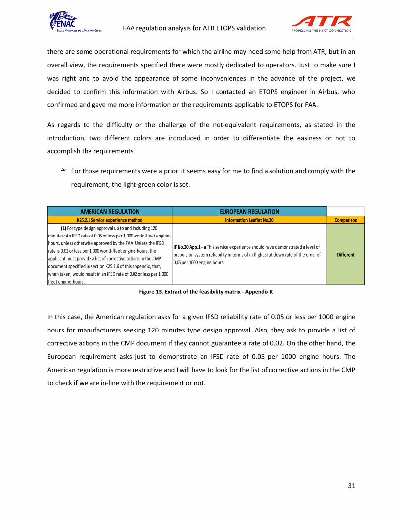
In this case, the American regulation asks for a given IFSD reliability rate of 0.05 or less per 1000 engine
hours for manufacturers seeking 120 minutes type design approval. Also, they ask to provide a list of
corrective actions in the CMP document if they cannot guarantee a rate of 0.02. On the other hand, the
European requirement asks just to demonstrate an IFSD rate of 0.05 per 1000 engine hours. The
American regulation is more restrictive and I will have to look for the list of corrective actions in the CMP
to check if we are in-line with the requirement or not.
AMERICAN REGULATION EUROPEAN REGULATIONK25.2.1 Service experience method Information Leaflet No.20 Comparison
(1) For type design approval up to and including 120
minutes: An IFSD rate of 0.05 or less per 1,000 world-fleet engine-
hours, unless otherwise approved by the FAA. Unless the IFSD
rate is 0.02 or less per 1,000 world-fleet engine-hours, the
applicant must provide a list of corrective actions in the CMP
document specified in section K25.1.6 of this appendix, that,
when taken, would result in an IFSD rate of 0.02 or less per 1,000
fleet engine-hours.
IF No.20 App.1 - a This service experience should have demonstrated a level of
propulsion system reliability in terms of in flight shut down rate of the order of
0,05 per 1000 engine hours.
Different
Figure 13. Extract of the feasibility matrix - Appendix K

FAA regulation analysis for ATR ETOPS validation
32 3
However, for those requirements which either I do not know anything about them or they seem
difficult to proof, they are identified in orange color.
In this requirement, no equivalent information in the IL has been found. Moreover, the ETOPS
Significant Systems is a concept not yet used in ATR. This requirement will require some extra help from
the specialists and I do not know a priori if the requirement is going to be challenging or not, so I decide
to categorize it with the orange color.
This second step helped me to develop my comprehension skills, as well as to know how to summarize
and understand a requirement. I sometimes found complicated to fully understand some requirements
because sometimes sentences are long and written in a “not common” English format.
On the other hand, I learnt how to trigger the requirements and look for both similarities as well as
differences. The importance here was to well distinguish if the requirements were equivalent or not. I
had to be really sure about it because one mistake here could change all the project in itself.
I took requirement by requirement, sentence by sentence and looking for an equivalent requirement in
the European regulation.
EUROPEAN REGULATIONAC No: 25.1535-1X (Draft mode) Appendix K Information Leaflet No. 20 Comparison
AMERICAN REGULATION
(4) Considering the maximum flight time per § K25.1.1 does not mean that the
numerical probability objectives (for example, 1 x 10⁻⁹/hr for a catastrophic failure
condition, 1 x 10⁻⁷/hr for a hazardous failure condition, etc.) for showing compliance
with § 25.1309(b) must be met solely by using the maximum flight time. For ETOPS
group 1 significant systems, an applicant may use the “maximum ETOPS mission
time” instead. For ETOPS group 2 significant systems, an “average ETOPS flight
duration” may be used. The average ETOPS mission time should be determined from
potential ETOPS routes available within the maximum range of the airplane. This
normally results in a longer average flight time than would be used for basic part 25
certification of non-ETOPS airplanes. For ETOPS group 1 significant systems, a
numerical probability analysis should always be calculated with an assumption that a
diversion following a system failure is a maximum length ETOPS diversion. For ETOPS
group 2 significant systems, the average ETOPS mission time used in numerical
probability analyses may be inclusive of all diversion times up to the maximum. The
exception for group 2 ETOPS significant systems would be for failure conditions that
are diversion time dependent. In those cases, the maximum ETOPS diversion time
should be used.
K25.1.1 No information Different
Figure 14. Extract of the feasibility matrix - AC25.1535-1X

FAA regulation analysis for ATR ETOPS validation
33 3
4.2.3 STEP 3: Make an assessment on the ATR case and define the meetings with experts
When the assessment was done, I looked carefully at each not-equivalent requirement. Before coming
up with a conclusion, I looked deeper on the information that was required. I used the internal material
from ATR and some documents, such as the MMEL, the AFM, the CMP, FCOM and the SDN chapters, in
order to know more and have the information to conclude. Then, in case of a not-equivalent
requirement were similar information was not found in the IL, the need of extra analysis should be
done. If I was not able to find the exact information by myself, meetings with the experts were defined
in order to find the answer.
Here, I set up meetings with different specialists depending on the requirement. For instance, I
contacted safety, electrical, icing, certification and maintenance specialists to answer some of my
question or doubts regarding the requirements.
In the meetings I set up, a previous preparation was done. In each meeting I defined well all the
problematic I had and my possible solutions. Then in the meetings, a power point presentation was
done or a paper to explain my problem and then we treated and dealt with it all together to reach a
conclusion. Sometimes the answers were found quickly but in some cases long discussions took place.
This part was the most interesting for me. I could translate the requirements “in paper” to the real
world of the aircraft itself. I learnt a lot of different things of the aircraft, I could go deeper in aspects
such as the electrical power sources or how the ice is attached to the wings.
To do it, what helped me a lot was the previous preparation of the meetings with the specialists. I had to
find the information in the different technical documents of ATR where information concerning the
electrical systems is found and so on.
Then, if questions appeared in this learning process, I noted them down and then they were discussed
with the specialists. I commented my doubts and possible approaches to the solution and they finally
gave me the answers.

FAA regulation analysis for ATR ETOPS validation
34 3
4.2.4 STEP 4: Evaluate the conclusions of the meetings and decide whether the
requirements are reachable / doable or not
Once the assessment was done for each not-equivalent requirement, together with the meeting
conclusions, I was able to decide whether the requirements were reachable or not for ATR.
With all the information gathered, I had to give a final answer for each requirement, that is, how we
were going to show compliance with each requirement.
I could say this last step was the most important one. I learnt to evaluate the conclusions of the
meetings or my analysis and reach or deliver a final answer to each requirement. I had to be very precise
on my answer because it could change all the study depending if I said we could achieve it or not.

FAA regulation analysis for ATR ETOPS validation
35 3
This study implied a high difficulty with the dealing of all the requirements because there were
a lot of them. This implied a high workload and here below an extract of the matrix I developed
is shown:
ETOPS COMPARISON BETWEEN APP K PART 25 AND IL No.20
K25.1 DESIGN REQUIREMENTS
AMERICAN REGULATIONK25.1.1 Part 25 compliance Information Leaflet No. 20 Comparison Comments Justification needed Department
The airplane-engine combination must comply with the
requirements of part 25 considering the maximum flight time and
the longest diversion time for which the applicant seeks approval.
IL No.20 - 10.f (1) (ii) In the case of operations cleared up to 120 minutes
maximum diversion time, small increases in the diversion time for specific routes
may be approved if it can be shown that the resulting routing will provide an
enhancement of overall safety. Such increases: (A) Will not exceed the
limitations given in the ETOPS type design approval (B) WIll not be more than
15 per cent of the original maximum diversion time approved in accordance with
10f.
Different
The only information in the IL related to this
paragraph of the appendix K is the one stated in the
left. However, this compliance should be easy to
proof. Is what we are looking for in this certification
progress
Yes
K25.1.2 Human factors Information Leaflet No. 20 - 7.e - Human Factors
An applicant must consider crew workload, operational
implications, and the crew's and passengers' physiological needs
during continued operation with failure effects for the longest
diversion time for which it seeks approval.
System failures or malfunctions occurring during extended range operation could
affect flight crew workload and procedures. Since the demands on the flight crew
may increase, an assessment should be made to ensure that exceptional piloting
skills or crew coordination are not required.
Equivalent No
K25.1.3 Airplane systems
(a) Operation in icing conditions
(1) The airplane must be certificated for operation in icing
conditions in accordance with § 25.1419No information provided Different ATR aircraft already comply with 25.1419 Yes
(2) The airplane must be able to safely conduct an ETOPS
diversion with the most critical ice accretion resulting from:
( (i) Icing conditions encountered at an altitude that the
airplane would have to fly following an engine failure or cabin
decompression.
(ii) A 15-minute hold in the continuous maximum icing
conditions specified in Appendix C of this part with a liquid water
content factor of 1.0.
(iii) Ice accumulated during approach and landing in
the icing conditions specified in Appendix C of this part.
IL No. 20 8b11. Airframe and propulsion ice protection should be shown to
provide adequate capability (aircraft controllability, etc) for the intended
operation.
This should account for prolonged exposure to lower altitudes associated with
the single engine diversion, cruise, holding, approach and landing.
Different
Possible with the implementation of technical notes
and analysis to justify ATR aircraft comply with this
requirements. ATR did an Assessment of ice
accretion on a feathered propeller as well as an
Assessment of performance effect of prolonged ice
accretion (Icing scenario, handling qualities), so we
should see if FAA accepts as well this studies and
there is no need to do a further analysis
Yes DIDIER CAILHOL
(b) Electrical power supply. The airplane must be equipped
with at least three independent sources of electrical power
IL No. 20 8.b (8) Three or more reliable and independent electrical power sources
should be available. As a minimum, following failure of any two sources, the
remaining source should be capable of powering the items specified in paragraph
8 b.(7).
Equivalent
The electrical power sources available on the ATR72-
212A & ATR42-500 are: one A.C.Wild Frequency
Generator which can be connected to a Transformer
Rectifier Unit (TRU) and a D.C. Stater-Generator,
both symetrically and independently installed on
each engine. The segregation of the generators
cable versus rotorburst introduced in the ATR72-200
ETOPS definition is inclucled in the ATR72-212A basic
definition. An A.C.Wild Generator associated to the
T.R.U. is capable of supplying the services specified
in paragraph 8b(7), but not a D.C. Startor-Generator.
The D.C. Startor Generator supplies all services
required for the previous ATR ETOPS certification,
that is paragraph 8b(7) excluding the weather radar,
the landing light, the static heating and the
windshield de-icing. The DGAC has accepted this
deviation based on the derivative nature of the
ATR72-212A & ATR42-500.The auto pilot is powered
in emergency configuration with a specific
modification included in the ATR72-212A CMP.
No
(c) Time limited system The applicant must define the system
time capability of each ETOPS significant system that is time-
limited.
IL No.20 - 8.c - (1) General The analysis and demonstration of airframe and
propulsion system failure effects and reliability provided by the applicant as
required by paragraph 8b, should be based on in-service experience as required
by paragraph 9, and the expected longest diversion time for extended range
routes likely to be flown with the aeroplane. If it is necessary in certain failure
scenarios to consider less time due to time limited systems, the latter will be
established as the maximum diversion time.
Different
In the CMP the time capability of the ETOPS
signifiant systems is described so we could use this
to address the FAA requirement
Yes
MAINTENANCE /
MICHAEL BOLIS
(AIRBUS)
K25.1.4 Propulsion systems
(a) Fuel system design Fuel necessary to complete an ETOPS
flight (including a diversion for the longest time for which the
applicant seeks approval) must be available to the operating
engines at the pressure and fuel-flow required by § 25.955 under
any airplane failure condition not shown to be extremely
improbable. Types of failures that must be considered include,
but are not limited to: crossfeed valve failures, automatic fuel
management system failures, and normal electrical power
generation failures.
IL No. 20 8.c (1) The analysis and demonstration of airframe and propulsion
system failure
effects and reliability provided by the applicant as required by paragraph
8b, should be based on in-service experience as required by paragraph 9,
and the expected longest diversion time for extended range routes likely to
be flown with the aeroplane. An assessment of the propulsion systems
reliability for a particular
airframe/engine should be made in accordance with paragraph 9 and
Appendix 1.
(ii) The analysis should consider:
(A) Effects of operation with a single-propulsion system (ie highpower
demands, bleed requirements, etc) and include possible
damage that could result from failure of the first propulsion
system.
(B) Effects of the availability and management of fuel for propulsion
system operation (ie cross-feed valve failures, fuel
mismanagement, ability to detect and isolate leaks, etc.).
ExemptedFollowing sec. 25.3, ATR is exempted from this
requirementNo
(1) If the engine has been certified for limited operation with
negative engine-fuel-pump-inlet pressures, the following
requirements apply:
(i) Airplane demonstration-testing must cover worst case
cruise and diversion conditions involving:
(A) Fuel grade and temperature.
(B) Thrust or power variations.
(C) Turbulence and negative G.
(D) Fuel system components degraded within their
approved maintenance limits.
(ii) Unusable-fuel quantity in the suction feed
configuration must be determined in accordance with § 25.959.
No information providedNot applicable to
ATR
ATR PW engines do not operate with negative
engine fuel pump inlet pressures, so this
requirement is not applicable. However, would be
interessant to check with powerplant department to
know more about the topic
No POWER PLANT
(2) For two-engine airplanes to be certificated for ETOPS
beyond 180 minutes, one fuel boost pump in each main tank and
at least one crossfeed valve, or other means for transferring fuel,
must be powered by an independent electrical power source
other than the three power sources required to comply with
section K25.1.3(b) of this appendix. This requirement does not
apply if the normal fuel boost pressure, crossfeed valve
actuation, or fuel transfer capability is not provided by electrical
power.
No information providedNot applicable to
ATR
ATR aircrafts want to certify 120 minutes, there is no
need to certify more than 180 minutesNo
(3) An alert must be displayed to the flightcrew when the
quantity of fuel available to the engines falls below the level
required to fly to the destination. The alert must be given when
there is enough fuel remaining to safely complete a diversion.
This alert must account for abnormal fuel management or transfer
between tanks, and possible loss of fuel. This paragraph does not
apply to airplanes with a required flight engineer.
No information provided ExemptedFollowing sec. 25.3, ATR is exempted from this
requirementNo
(b)APU design. If an APU is needed to comply with this appendix,
the applicant must demonstrate that:
(1) The reliability of the APU is adequate to meet those
requirements; and
(2) If it is necessary that the APU be able to start in flight, it is able
to start at any altitude up to the maximum operating altitude of
the airplane, or 45,000 feet, whichever is lower, and run for the
remainder of any flight .
No information providedNot applicable to
ATRATR aircraft do not have APU No
(c)Engine oil tank design. The engine oil tank filler cap must
comply with § 33.71(c)(4) of this chapter. (4) --> 33.71(c) (4) Each
oil tank cap must provide an oil-tight seal. For an applicant
seeking eligibility for an engine to be installed on an airplane
approved for ETOPS, the oil tank must be designed to prevent a
hazardous loss of oil due to an incorrectly installed oil tank cap.
No information provided ExemptedFollowing sec. 25.3, ATR is exempted from this
requirementNo
Figure 15. Extract of th ETOPS feasibility matrix developed by myself

FAA regulation analysis for ATR ETOPS validation
36 3
4.2.5 Case study (requirements)
In this internship I analyzed a lot of requirements. However, in this report I am going to just study the
most important ones as well as the ones that have been more challenging for me. Please note that I am
just going to go deeper in the explanations for a requirement concerning the electrical power sources.
The other ones will be discussed in the Annexes.
Electrical power sources requirement
Icing requirements (see Annex 11.2)
Time-limits / ETOPS Significant Systems requirement (see Annex 11.3)

FAA regulation analysis for ATR ETOPS validation
37 3
4.2.6 Electrical power sources requirement
Analyzing the different requirements in the Appendix K to Part 25 (FAA regulation), I found one
concerning the electrical power supply systems for ATR aircraft. It asks the following:
FAA requirement
K25.1.3 Airplane systems
b. Electrical power supply. The airplane must be equipped with at least three independent sources of
electrical power.
A priori, this requirement seems easy to understand. It basically asks the aircraft to have three
independent sources of electrical power at minimum. However, the interpretation of “independent” can
be somehow tricky depending on some considerations.
Therefore, let’s see if there is some equivalent information in the Information Leaflet (EASA side).
EASA requirement
The information found is the following:
Three or more reliable and independent electrical power sources should be available. As a minimum,
following failure of any two sources, the remaining source should be capable of powering the items
specified in paragraph 8.b(7). If one or more of the required electrical power sources are provided by an
APU, hydraulic system, or ram air turbine, the following criteria apply as appropriate:
(i) The APU, when installed, should meet the criteria in paragraph 8 b (4).
(ii) The hydraulic power source should be reliable. To achieve this reliability, it may be necessary to
provide two or more independent energy sources (e.g. bleed air from two or more pneumatic sources).
(iii) The Ram Air Turbine (RAT) should be demonstrated to be sufficiently reliable in deployment and use.
The RAT should not require engine dependent power for deployment.
In the first sentence, some equivalent information with respect to FAA requirement can be identified.
They basically ask for the same, to have a minimum of 3 independent electrical power sources.
However, analyzing the whole requirement I noticed that there are some points that they are not
applicable for ATR aircraft. Let’s have a look:
Figure 17. Extract of the Information Leaflet No. 20
Figure 16. Extract of the Appendix K to part 25

FAA regulation analysis for ATR ETOPS validation
38 3
Three or more reliable and independent electrical power sources should be available. As a minimum,
following failure of any two sources, the remaining source should be capable of powering the items
specified in paragraph 8.b(7). If one or more of the required electrical power sources are provided by an
APU, hydraulic system, or ram air turbine, the following criteria apply as appropriate:
(i) The APU, when installed, should meet the criteria in paragraph 8 b (4). ATR aircraft does not have
an APU
(ii) The hydraulic power source should be reliable. To achieve this reliability, it may be necessary to
provide two or more independent energy sources (e.g. bleed air from two or more pneumatic sources).
ATR aircraft does not use hydraulic power as an electrical power source
(iii) The Ram Air Turbine (RAT) should be demonstrated to be sufficiently reliable in deployment and use.
The RAT should not require engine dependent power for deployment. ATR aircraft does not have a
RAT
In red my justifications on the different requirements not applicable to ATR are found. For the first one, I
had to check the different power units to produce energy on the aircraft and I found that ATR has no
APU. For the second one, I had to check the different type of sources on the ATR to produce power. On
ATR though, there is no use of hydraulics to generate electrical power. All the electrical power is
produced mainly by the Starter Generators and Alternative Current Frequency Generators. Finally,
concerning the Ram Air Turbine, ATR aircraft do not need and do not use the RAT.
Analysis and comparison of the requirement
Therefore, a final comparison between both requirements can be done, and resuming we have:
FAA EASA
Electrical power supply. The airplane
must be equipped with at least three
independent sources of electrical
power.
Three or more reliable and independent electrical
power sources should be available. As a minimum,
following failure of any two sources, the remaining
source should be capable of powering the items
specified in paragraph 8.b(7).
Figure 18. Extract of the IL No. 20 with my notes

FAA regulation analysis for ATR ETOPS validation
39 3
The only difference right now remains in extent of the EASA requirement asking for a list of items that
should be powered by the remaining source in case of failure of any two sources.
As a first approach, I would categorize this requirement as equivalent. However, this list of items should
be checked just in case a problem could appear.
Moreover, to make sure ATR already complied with this requirement, I decided to look at how did ATR
show compliance to EASA in the previous ETOPS certification. There, the answer given was not so
straightforward and not clearly documented concerning the independency of the electrical power
sources. This is the reason why I decided to go deeper and understand how the electrical systems of ATR
aircraft work. This means, doing an assessment on the ATR case so as to verify if the aircraft is still
compliant with the FAA regulation.
Assessment on the ATR case and define the meetings with experts
Here below, a study of how the electrical systems of ATR work is done, in order to be able to reach a
conclusion of the requirement discussed before. Meetings will also take place, depending on the needs I
have.
Electrical power sources of ATR aircraft
In order to analyze the electrical requirements of the American regulation concerning ETOPS it is
necessary to understand which the electrical power sources of the ATR aircraft are.
The information used to acquire knowledge of the electrical power sources comes from the visits to
electrical power generation specialists, the ATA Chapter 24, previous technical notes, presentations and
studies done by ATR as well as a visit to the aircraft itself in the Final Assembly Line of ATR in Saint-
Martin.
The study done is summarized here below:

FAA regulation analysis for ATR ETOPS validation
40 3
Figure 20. Alternative current (constant frequency)
a) Main power sources
The equipment and systems on board the ATR aircraft use different type of current depending its
purpose and function. The power sources are the equipment in charge of supplying the current that the
systems need to work. Three main types of current exist, the direct current, the alternative current
(constant frequency) and alternative current (variable frequency).
As said, each current has its own properties and depending on the function we need, a system will work
properly with one type of current or another.
Basically, on the ATR, the current can be obtained from the following sources (data obtained from
bibliography [8]):
- DC supplying
o Batteries (main & emergency)
o DC generators driven by the accessory gearboxes
o DC GPU (Ground Power Unit DC)
o TRU (Transformer Rectifier Unit)
- AC supplying
o The AC (115/26V 400Hz) is supplied by
Static Inverter (from the DC)
o The ACW (115V variable frequency) is supplied by
ACW generators driven by the reduction gearboxes
AC GPU (Ground Power Unit AC) (ACW GPU doesn’t exist. The AC GPU
supply the ACW busses, with the 115V/400Hz, that is suitable)
Figure 19. Direct current Figure 21. Alternative current (variable frequency)

FAA regulation analysis for ATR ETOPS validation
41 3
These are all the sources of obtaining electricity on the ATR aircraft.
b) DC generation
The Starter Generator is the normal DC power source; it is driven by an engine’s turbine through a
reduction gearbox. It is also used to start engines. In addition, it is connected to a Static Inverter, which
allows to convert DC to AC current.
Figure 23. DC-Starter Generator
Depending on the equipment, they can be powered by DC (Direct Current) or AC (Alternative Current)
thanks to the different buses distributed in the aircraft.
For the DC generation, the electrical circuit associated is the following one:
Figure 22. DC Starter-Generator Figure 24. Static inverter
Figure 25. DC generation electrical circuit

FAA regulation analysis for ATR ETOPS validation
42 3
On the left side there are the 2 DC Starter-Generators and then all the different buses they supply, as
well as the Static Inverters which helps to provide AC current though the AC Main and Standby buses.
Batteries
Moreover, there are two batteries capable of providing DC current installed on the aircraft, the main
battery and the emergency battery. The MAIN battery has a nominal capacity of 43 Ah and the EMER
battery of 15 Ah
These batteries provide DC power to the emergency network when starter generators and TRU are no
more available. The Main battery is used as well to supply Starter Generators during engine starting.
In the event of an emergency the batteries are used as follows:
- The main battery supplies
o DC ESS BUS
o DC STBY BUS
o INV 1 (which supplies 115 and 26VAC STBY buses only)
- The EMER battery supplies
o DC EMER BUS
c) AC generation
On the other side, The AC Wild Frequency Generator can convert AC to DC thanks to the TRU. Each ACW
Generator is driven by a reduction gearbox on propeller.
Figure 26. Main battery Figure 27. Emergency battery

FAA regulation analysis for ATR ETOPS validation
43 3
On the other hand, for the AC generation with the ACWF generators, the electrical circuit is the
following:
In this case there are the two AC generators, both connected with a GCU. The GCU provides a
permanent protection, control and monitoring of the generators. One Bus Power Control Units (BPCU) is
connected to both AC GCUs. In case DC power is needed, there is the TRU (Transformer Rectifier Unit)
which allows to convert ACW power into DC power.
Figure 28. AC Wild Frequency Generator Figure 29. AC WIld Frequency Generator Figure 30. Transformer Rectifier Unit
GC : Generator contactor TC : TRU contactor GCU : Generator control unit BTC : Bus tie contactor GXC : Ground service
EXC : Bus contactors
EPC : Ext power contactor
BPCU : Bus power control unit Figure 31. ACWF generation electrical circuit

FAA regulation analysis for ATR ETOPS validation
44 3
Summing up, in the figure below the schema of the different electrical power sources of ATR aircraft can
be seen:
Now, after this preliminary study we can retake the analysis of the electrical requirement concerning the
different airplane functions that need to be powered by the European regulation.
Airplane functions needed to be powered
Airplane functions that need to be powered by EASA
Now there is the need to see which systems must be powered by a single electrical source (specified in
the original requirement from EASA discussed before).
So, I went to look at the paragraph 8.b(7) in the IL20 to see which the items required are:
“Functions to be provided may differ between airplanes and should be agreed with the Authority. These
should normally include:”
Item Airplane functions
i Attitude information
ii Adequate radio communication and intercommunication capability
iii Adequate navigation capability (including weather radar)
iv Adequate cockpit and instrument lighting, Emergency lighting and landing lights
v Sufficient captain and first officer instruments, provided cross-reading has been
2 STATIC INVERTERS (AC CONSTANT FREQUENCY
2 BATTERIES
PROPELLER DRIVEN
AC WILD FRENQUENCY
ALTERNATORS
ENGINE DRIVEN
DC STARTER GENERATORS
Figure 32. ATR aircraft with the different electrical power sources

FAA regulation analysis for ATR ETOPS validation
45 3
evaluated
vi Heading, airspeed and altitude including appropriate pitot/static heating
vii Adequate flight controls including auto-pilot
viii Adequate engine controls, and restart capability with critical type fuel (from the stand-
point of flame out and restart capability) and with the
ix Airplane initially at the maximum relight altitude
x Adequate fuel supply system capability including such fuel boost and fuel transfer
functions that may be necessary
xi Adequate engine instrumentation
xii Such warning, cautions, and indications as are required for continued safe flight and
landing
xiii Fire protection (cargo, APU and engines)
xiv Adequate ice protection including windshield de-icing
xv Adequate control of cockpit cabin environment including heating and pressurization
xvi ATC Transponder
Airplane functions that need to be powered by FAA
Here, I decided to look in the AC25.1535 in draft status to see if there was some extra information on it.
In the Advisory Circular in draft status from FAA (AC 25.1535) they also list the different set of airplane
system functions needed to be powered by an electrical power source:
“(7) An applicant should propose and justify the minimum set of airplane system functions
required for: “
Item Airplane functions
1 Continued safe flight and landing in the approved operating environment considering a
maximum duration diversion;
2 Flight control capability;
3 Autopilot/auto throttle capability;
4 Navigational capability;

FAA regulation analysis for ATR ETOPS validation
46 3
5 Communications capability;
6 Operating in the air traffic environment (lighting, transponder, radios, SATCOM, TCAS,
ground proximity warning system, etc.);
7 Flight deck environmental control;
8 Cabin environmental control; and
9 Emergency lighting control.
Crosscheck between airplane functions
So, after analyzing and understanding which were the functions required, I decided to realize a
crosscheck between both regulations to see if all the items could be covered or not. In case there was an
item not covered, the need for further analysis would be required.
FAA regulation EASA regulation
(a) Continued safe flight and landing in the approved operating environment considering a maximum duration diversion (b) Flight control capability (c) Autopilot/autothrottle capability (d) Navigational capability (e) Communications capability (f) Operating in the air traffic environment (lighting, transponder, radios, SATCOM, TCAS, ground proximity warning system, etc.) (g) Flight deck environmental control (h) Cabin environmental control (i) Emergency lighting control
(a) Attitude information (b)Adequate radio communication and intercommunication capability (c) Adequate navigation capability (including weather radar) (d) Adequate cockpit and instrument lighting, Emergency lighting and landing lights (e) Sufficient captain and first officer instruments, provided cross-reading has been evaluated (f) Heading, airspeed and altitude including appropriate pitot/static heating (g) Adequate flight controls including auto-pilot (h) Adequate engine controls, and restart capability with critical type fuel (from the stand-point of flame out and restart capability) and with the (i) Airplane initially at the maximum relight altitude (j) Adequate fuel supply system capability including such fuel boost and fuel transfer functions that may be necessary (k) Adequate engine instrumentation (l) Such warning, cautions, and indications as are required for continued safe flight and landing (m) Fire protection (cargo, APU and engines) (n) Adequate ice protection including windshield de-icing (o) Adequate control of cockpit cabin environment including heating and pressurization (p) ATC Transponder.

FAA regulation analysis for ATR ETOPS validation
47 3
The conclusion of the crosscheck I did is that all the different functions requested by FAA regulation
were already covered by the IL regulatory document. In addition, I could say the list asked by the
European side was even more restrictive than the American one, so with this issue we should not have
any problem to show compliance for the ETOPS type design approval by the FAA:
That said, the only problem that could appear could be in terms FAA’s interpretation of the
requirements. Some experts I contacted from Airbus or inside ATR said the FAA sometimes is special in
this kind of things. For us though, there is no blocking item. I checked all items one by one, meaning that
I took each aircraft function from the FAA list, for instance, “(d) Navigational capability” and I tried to
look if a similar information was found in the EASA list.
To navigate, you need to know your position, speed, altitude and so on in order to navigate through the
airspace. Once I understood what the regulation meant by “Navigational capability” I went to look in the
EASA list if equivalent information was written. What I found was “(a) attitude information” and “(f)
heading, airspeed and altitude including appropriate pitot/static heating”.
With this equivalent information, I consider this requirement covered, and the same procedure was
done for all the items required.
Up to now, everything was fine. However, when I finished the comparison between these two
requirements from the FAA side and the one in the EASA, I looked in the ETOPS compliance matrix done
by ATR in the previous ETOPS certification process to see which means of compliance they used and how
they justified each requirement. And here I found some vital information that cannot be
underestimated. In the previous ETOPS certification process ATR had one exemption on the
requirement concerning the electrical power supply.
An exemption is a grant of relief to an applicant from the requirement of a specified airworthiness
standard. A petition for exemption follows the procedures for public comment on rulemaking that are
described in FAR 11. The applicant should submit a petition for exemption to the FAA accountable
directorate through the ACO. The FAA considers the following before granting an exemption: the
requested exemption must benefit the public as a whole; and, granting this relief would either not

FAA regulation analysis for ATR ETOPS validation
48 3
adversely affect safety or the exemption would provide a level of safety at least equal to that provided by
the rule from which relief is sought.
After this definition, the answer ATR gave (and that EASA accepted) to address this requirement was:
“The electrical power sources available on the ATR72-212A & ATR42-500 are: one A.C.Wild Frequency
Generator which can be connected to a Transformer Rectifier Unit (TRU) and a D.C. Starter-Generator,
both symmetrically and independently installed on each engine. The segregation of the generators cable
versus rotor burst introduced in the ATR72-200 ETOPS definition is included in the ATR72-212A basic
definition. An A.C.Wild Generator associated to the T.R.U. is capable of supplying the services specified
in paragraph 8b(7), but not a D.C. Starter-Generator. The D.C. Starter Generator supplies all services
required for the previous ATR ETOPS certification, that is paragraph 8b(7) excluding the weather
radar, the landing light, the static heating and the windshield de-icing. The DGAC has accepted this
deviation based on the derivative nature of the ATR72-212A & ATR42-500.The auto pilot is powered in
emergency configuration with a specific modification included in the ATR72-212A CMP.”
EASA accepted this exemption.
It is important to notice that this exemption is going to be a key point when validating ETOPS by the
FAA. We have a constraint and ATR will ask for the same treatment to FAA in order to proceed. The
exemption allows ATR to be exempted of a specific regulatory paragraph that cannot comply with, so if
the FAA rejects the exemption petition, difficulties will appear to continue this ETOPS project.
After the appearance of this exemption, I wanted to know why the four equipment listed in this
document could not be powered, because if we had to justify to FAA why we should be granted this
exemption, we had to have the information. So I looked for the previous ETOPS certification for ATR
where all the applicable technical notes and documents are kept.
There, I found some useful information for trying to solve the issue and for me to be able to reach a
conclusion.
First of all, there was a document, the Emergency Loads Analysis, which concluded saying that the DC
Starter-Generator could supply all services except the weather radar, meanwhile the ACWF generator

FAA regulation analysis for ATR ETOPS validation
49 3
could supply all services except the static heating, windshield de-icing and landing lights in case of
failure.
This information was not in line exactly with the answer in the ETOPS compliance matrix that ATR did,
there were some ambiguities between the documents.
So I had to find out which was the correct statement about this exemption, to know which were
specifically the systems that could not be powered as well as which type of current they needed to be
powered, because it depends if there is a loss of DUAL AC or DUAL DC.
Failure scenarios:
Before the setting of the meetings with the electrical specialists, I decided as well to deeply analyze the
4 systems that could not be powered in case of failure because it was not clear in which case they were
not supplied.
In the ETOPS analysis, different failure scenarios must be considered. Normally, the worst possible
scenarios should be studied. In our case, in terms of electrical power sources, the studies always take
into account the loss of one engine and then, the failure of another electrical power source from the
remaining engine.
If even within this scenario safety levels remain inside the margins, this means we are compliant.
The 2 worst possible scenarios that can happen in flight are the dual DC Generation loss or the dual AC
Generation loss, because you lose the DC or the AC current from the two sources that produce this type
of current. In practical terms, is the same as if you lose one engine and one power source of the other
engine available.
Scenario 1 Scenario 2
Figure 33. Failure scenarios studied
AC Generation loss DC Generation loss

FAA regulation analysis for ATR ETOPS validation
50 3
I looked carefully at each of the four equipment, especially in the SDN, where I found the type of current
they needed to work as well as their specific functions and the connections.
Once I had the information, I then decided to set up a meeting with the electrical systems specialists to
clear out this issue.
A meeting was held with the electrical systems specialists, where I showed them my questions as well
the slight discrepancy and they took the action to solve the issue.
In the meeting, basically I checked if the hypothesis we did concerning the 4 equipment were good or
not, and about the static heating they were not sure whether it was powered with AC or DC current.
Moreover, with the new aircraft versions, maybe the loads analysis were changed and the aircraft could
already power this equipment without the need of the exemption. So an open action was let to them to
check this issue.
In the end, after some weeks of exchanges and the contact of some Airbus specialists, I reached the final
answer.
I came up with the following conclusions, confirmed by the electrical specialists.
In the case where there is a dual DC Generators loss, the equipment that CANNOT be powered
is:
o Static heating
o Weather radar
In the case where there is a dual AC Generators loss, the equipment that CANNOT be powered
is:
o Landing lights
o Windshield de-icing
This is the reason why an exemption was sought by ATR when applying for the ETOPS capability by
EASA/DGAC.
As said before, FAA should accept the same exemption in order to avoid redesigning the electrical circuit
design or the electrical system architecture of the ATR aircraft.

FAA regulation analysis for ATR ETOPS validation
51 3
Dual DC Starter-Generator loss Dual AC Wild Frequency Generator loss
Static heating NO YES
Weather radar NO YES
Landing lights YES NO
Windshield de-icing YES NO
In parallel with the meetings held with the electrical specialists, in the weekly meeting done with FAA
the topic of the exemption came out (see Annex 11.1) and they advertised us to ask for the exemption
as soon as possible in order to make sure no blocking item would be found as the certification process
advances.
As soon as I heard that an exemption should be prepared, I was enthusiastic about the idea of doing it,
at least, writing a draft that then could be used by ATR. So I asked with no hesitation the Foreign
Authorities Certification Manager of ATR, to see whether I could do it or not. He answered yes, so I
started looking information regarding the exemption (see Annex 11.1).
Redaction of the Exemption
Once I received the confirmation from the Manager, I first looked for some exemptions already granted
by FAA, some examples by internet and I gathered some information from books and websites.
Once I had all information and I understood how it worked and the different steps to do, I started to
work on it.
I structured the exemption (Annex 11.1) in 4 different parts: an introduction, the applicable regulation, a
discussion and the conclusion and petition.
First of all, I did some brainstorming to collect all the information I had together.
Information coming from documentation such as the ATA Chapters, as well as previously certification
items such as the ETOPS compliance matrix was gathered.

FAA regulation analysis for ATR ETOPS validation
52 3
In addition, the conclusions of the meetings I did were compiled, where I could ask the questions I had
concerning this issue, as well to get a confirmation of my comments.
Also, I need to justify why the exemption would not compromise safety levels, so with the help from the
CRI I could justify each equipment like that:
For the weather radar, due to the fact that the ATR 42-500 has slower one engine operative
speed (about 200 kts TAS at 10 000 ft ISA) than jets which have the same requirements, the
weather situation and forecasted data are much more reliable for the closer diversion airport of
turboprops than they are for jets with the same diversion duration.
For the landing light, in case of failure of both A.C. Wild Frequency generators, the DC
generation would still be able to power the following exterior lights allowing the aircraft to be
seen: the navigation lights, the anti-collision light and the wing and engine scanning lights.
Moreover, crews are trained for night landing without landing light on classic runways.
For the static ports, their location and shape with regard to the relative wind are such that they
should never get clogged by ice accretion in flight in normal icing conditions.
For the windshield de-icing, in case of failure of both A.C. Wild Frequency generators, the
remaining D.C. generator is still able to power both side windows heating and both windshield
wipers. In addition, during the basic certification process of the ATR 42-300, the flight test
program reference 1265/85 and the corresponding certification card 25-10-06 demonstrated
that landing with both windshield obstructed was possible and safe using lateral windows.
All these justifications were agreed both by me, my tutor and the specialists. These justifications were
found according to experience, technical notes, previous knowledge and studies done.
Therefore, I came up with the draft of the exemption and forwarded to the certification team. Now, it
needs to be reviewed by the managers and then submitted to FAA.
The realization of this exemption made me win more knowledge as well as knowing another aspect
done in the certification office of a company. I was able to produce a technical note with lot of different
agents involved, meaning certification specialists, electrical specialists, documentation and regulation.

FAA regulation analysis for ATR ETOPS validation
53 3
So, with all this analysis, I can proceed to obtain the conclusions. Now, a final study of the independency
of the different electrical power sources of ATR aircraft can be done.
First of all we can neglect the batteries as a mean of being an independent electrical source. One could
wonder that why not the batteries could be another electrical independent power source. Well, the
answer to this question is that looking in the technical specifications of the batteries in the SDN Chapter
24 concerning electrical power, they have an endurance around 30 minutes. However, for ETOPS they
should be available the minimum time that the manufacturer seeks approval, this is, 120 minutes,
because with an endurance of 30 minutes if the engine of the aircraft fails when the aircraft is at the
maximum diversion time (120 minutes) the airplane would not be able to arrive to the closest diversion
airport and would have to land to the water or the earth with catastrophic consequences.
Showing independency
Therefore, to show independency between each power source, the generation of electrical power must
be done alone without any interdependency with other elements which are used for another circuit.
The justification of 3 electrical power sources is not trivial. A big effort was done in this study because it
was not clear.
1st electrical power source: The first power source identified is the DC Starter-Generator of the left
engine, the Engine 1. This generator can be connected to the Static Inverter to transform DC to AC
current too. It has its own electrical circuit independent of the others, with the different buses
associated and tie contactors, but guaranteeing the circuit is completely independent of the other
electrical installations.
2nd electrical power source: The second power source is the DC Starter-Generator of the right engine,
the Engine 2. As for the DC of the engine 1, this engine can be connected to another independent Static
Inverter to produce as well AC current.
3rd electrical power source: The third and last power source is both the ACWF generators connected to
the TRU. ATR aircraft have just a single TRU (Transformer Rectifier Unit), meaning that when showing
independency, one ACWF connected with the TRU can supply AC and DC current but then, with the
remaining ACWF generator, there is not a second TRU associated so no DC power can be supplied. That
said, the independency of a possible 4th power source cannot be considered.
I sent all my studies to the electrical specialists, who confirmed positively my hypothesis and analysis.

FAA regulation analysis for ATR ETOPS validation
54 3
Conclusion:
Summing up, I can confirm that ATR have three independent electrical power sources. ATR could comply
with the requirement of FAA subject to the approval of the exemption on the 4 equipment that cannot
be powered in case of any failure not shown to be extremely improbable. This requirement is not a
blocking item. However, the exemption should be obtained as well as ATR received the exemption from
the EASA.
1st
power source
2rd
power source
3rd
power source
Figure 34. ATR main electrical power sources

FAA regulation analysis for ATR ETOPS validation
55 3
5. ENAC courses related with the internship
This internship was the perfect way to give continuity to the studies I did at ENAC.
The last year of the “Ingénieur ENAC” program I did had different subjects related to airworthiness,
where a direct link can be made with my internship.
This internship allowed me to use and implement all the knowledge learnt at class.
The major in Air Operations and Safety offers a huge variety of courses, giving special attention to
airworthiness and certification. There is a main block of courses called Aeronautical Safety where
subjects as structures airworthiness, engine certification and aircraft systems certification are taught.
These subjects offer the possibility to get familiarized with certification aspects as well to see how the
certification of different systems or parts of the aircraft is done.
Specially, there was one subject that I found really interesting and from which I learned a lot that was
the structures airworthiness course. Teachers from EASA came to teach us how structures are certified
and an overall description of the aircraft structures was done. Also, aspects such as fatigue limits, aero
elasticity, corrosion or ditching were studied.
Apart from the exam in the end of the lessons, we had to perform an EASA training “Structure
airworthiness” case study.
There, there was a task which has helped me a lot in this internship, and it was about the comparison
between different requirements.
The case study asked to “List and describe with your own words the differences between CS-25.571 and
CS-23.571 and following paragraph (23.572, 23.573, 23.574, 23.575) for both requirements and
acceptable means of compliance.”
This requirements comparison has a direct similarity with the second step of the process defined in my
internship in ATR, so it really helped me the study and analysis of this exercise done at class.

FAA regulation analysis for ATR ETOPS validation
56 3
6. ETOPS real project and personal contributions
ATR sent the application letter for Modification 4711 (ETOPS operations) to the FAA on ATR 42-500 and
72-212A on 13th February 2017. The same day my internship started.
In the application letter, more documents were attached, such as the EASA approval for ETOPS, the CMP
or the AFM. The idea is to validate the ETOPS capability by the FAA because ATR already followed the
certification process by EASA.
There is a permanent contact between ATR and the FAA. Moreover, each month a meeting with the FAA
takes place, where all open actions are discussed and the next steps are agreed.
On 4th May, a mail from the FAA was received in answer to the application ATR did in February. They
asked to provide the individual certification plans for a given list of the applicable sections of the
appendix K. (Remember that the appendix K is the document containing all the requirements concerning
ETOPS type design approval).
Here, I was in charge of the answer to this email, so as I had already done the preliminary analysis of the
comparison between FAA and EASA requirements, I could identify the crosscheck between the items
they were requesting and the ones in the European regulations. That said, a reply was sent from ATR the
30th May containing the information I had prepared.
After this email sent to the FAA I started attending the FAA monthly meetings organized between FAA
and ATR, where ETOPS subject appeared as one of the main points of the meeting. All progresses,
questions, or topics related to the ETOPS subject were treated and discussed.
Thanks to the Foreign Authorities Certification Manager, I had the possibility to attend these meetings
done by conference call. The application used to connect all the participants is called WebEx.
These meetings are always attended by ATR members and EASA and FAA representatives. ATR has some
focal points inside the Authorities (Project Certification Managers) who help manage all the
coordination between institutions.
So in this meeting there were both EASA PCM and FAA PCM and 4 certification engineers from ATR.

FAA regulation analysis for ATR ETOPS validation
57 3
The working principle of these meetings is always the same. There is a list of open actions between ATR
and FAA reviewed monthly to check their progress. There were subjects submitted for validation such as
ongoing projects submitted for FAA validation (including ETOPS), TCDS updates, etc.
Here I had the chance to participate and join the discussion with FAA with the ETOPS issue.
First of all, we discussed our answer with FAA PCM. He told us he had already forwarded the
information to the specialists. Moreover, an important aspect we discussed about was the possibility to
be granted an exemption concerning a requirement for the type design approval for ETOPS. This
exemption concerns 4 equipment which cannot be powered in case of any failures not shown to be
extremely improbable. ATR was already granted this exemption by EASA but we will need FAA to accept
it as well.
Here, FAA PCM said that if this exemption was accepted by EASA, a priori FAA should do the same, but
the application for the exemption should be done anyway.
He finally concluded that he would talk us back when he had news from his specialists about our email.
On June 14th we received the answer. What they finally want is ATR to provide a full ETOPS compliance
matrix with all the applicable requirements as well as the means of compliance that are going to be
used. Furthermore, the service experience data ATR plans to use for showing compliance to the sections
of appendix K should also be provided.
Here below, the ETOPS subject between ATR and FAA is shown, with all the actions needed to be done.
In blue, the action for the application for the exemption was introduced in the last meeting, where we
discussed that the exemption should be written.
Priority Subject Mod Action Owner Status
Medium 3
ETOPS
(MAJOR
SIGNIFICANT)
4711
ATR to provide application letter (Mail from
Manuel dated 13 February 2017) ATR Closed
FAA to continue discussion and exchange of
documents with ATR FAA Open

FAA regulation analysis for ATR ETOPS validation
58 3
FAA to provide IP's FAA Open
ATR to provide position on FAA IP's ATR
EAC Open
FAA to close IP's FAA Open
FAA to provide delegation letter to EASA FAA Open
ATR to provide DoC ATR
EAC Open
EASA to provide SoC to FAA EASA Open
Application for exemption ATR
EAC Open
FAA to provide approval letter FAA Open
So, I let all my matrix prepared with all the information needed to create the final ETOPS compliance
matrix with a folder as well containing all the different documents I produced and technical notes, as
well as data to attach to the compliance matrix to show compliance.
It was not expected, but the ETOPS project became an important subject in the certification office. That
said, the last month of the internship the certification team agreed to start designing the final ETOPS
compliance matrix, and with the help of another member in the certification, we started the ETOPS
compliance matrix with the help of my ETOPS feasibility matrix.
I really appreciated that the ETOPS issue got prioritized, because I could see how my work was useful for
the company and that all the things I did were valued by the team. It was really rewarding.
Here below, an extract of the ETOPS compliance matrix can be seen, not ready yet because it will take
still some time to be finished, with all the different means of compliance that exist to prove conformity
with the requirements:

FAA regulation analysis for ATR ETOPS validation
59 3
0 1 2 3 4 5 6 7 8 9
FAR 25 amdt 120
MC
0:
Com
plia
nce S
tate
ment
MC
1:
Desig
n R
evie
w
MC
2:
Calc
ula
tion/A
naly
sis
MC
3:
Safe
ty A
ssessm
ent
MC
4:
Labora
tory
Tests
MC
5:
Gro
und T
ests
on r
ela
ted p
roduct
MC
6:
Flig
ht
Tests
MC
7:
Desig
n I
nspection/A
udit
MC
8:
Sim
ula
tion
MC
9:
Equip
ment
Qualif
ication
25.3(a)Applicability. This section applies to an applicant for ETOPS type design approval of an
airplane:x Noted
25.3(a)(1) That has an existing type certificate on February 15, 2007; or N/A
25.3(a)(2)For which an application for an original type certificate was submitted before February 15,
2007.x Noted
25.3(b) Airplanes with two engines. x Noted
25.3(b)(1)
For ETOPS type design approval of an airplane up to and including 180 minutes, an
applicant must comply with Sec. 25.1535, except that it need not comply with the following
provisions of Appendix K, K25.1.4, of this part:
(i) K25.1.4(a), fuel system pressure and flow requirements;
(ii) K25.1.4(a)(3), low fuel alerting; and
(iii) K25.1.4(c), engine oil tank design.
x Noted
25.3(b)(2)For ETOPS type design approval of an airplane beyond 180 minutes an applicant must
comply with Sec. 25.1535.x Noted
25.3(c)
Airplanes with more than two engines. An applicant for ETOPS type design approval must
comply with Sec. 25.1535 for an airplane manufactured on or after February 17, 2015,
except that, for an airplane configured for a three person flight crew, the applicant need not
comply with Appendix K, K25.1.4(a)(3), of this part, low fuel alerting.
N/A
25.1535Except as provided in Sec. 25.3, each applicant seeking ETOPS type design approval
must comply with the provisions of Appendix K of this part.x Noted
This appendix specifies airworthiness requirements for the approval of an airplane-engine
combination for extended operations (ETOPS). For two-engine airplanes, the applicant
must comply with sections K25.1 and K25.2 of this appendix. For airplanes with more than
two engines, the applicant must comply with sections K25.1 and K25.3 of this appendix.
xRef. DTY-2133-12 Iss. 02 - MOD 5948
Certification Programme
K25.1.1 Part 25 compliance
The airplane-engine combination must comply with the requirements of part 25 considering
the maximum flight time and the longest diversion time for which the applicant seeks
approval.
x Noted
K25.1.2 Human factors
An applicant must consider crew workload, operational implications, and the crew's and
passengers' physiological needs during continued operation with failure effects for the
longest diversion time for which it seeks approval.
x
K25.1.2 is equivalent to JAA IL20.7.e
Ref. DO/TY-4511/09 Iss. 02 - MOD 5948
human factors certification plan
(1) The airplane must be certificated for operation in icing conditions in accordance with
Sec. 25.1419.x
Statement: ATR42/72 already comply
with JAR 25.1419 (refer TCDS A53EU),
which is equivalent to FAR 25.1419 amdt
25-72.
(2) The airplane must be able to safely conduct an ETOPS diversion with the most critical
ice accretion resulting from:
(i) Icing conditions encountered at an altitude that the airplane would have to fly following
an engine failure or cabin decompression.
(ii) A 15-minute hold in the continuous maximum icing conditions specified in Appendix C
of this part with a liquid water content factor of 1.0.
(iii) Ice accumulated during approach and landing in the icing conditions specified in
Appendix C of this part.
x
K25.1.3(a) is more restrictive than JAA
IL20.8.b(11), but ATR aircraft already
comply with FAA regulation for icing
requirements.
Ref. icing analysis reports 420.5105-96
Iss. 01, 457.0192-93 Iss. 01, 457.0665-
96 Iss. 01, 519.0703-97 Iss. 01,
540.5049-97 Iss. 01 & 542.5048-97 Iss.
01
K25.1.3(b) Electrical power supply The airplane must be equipped with at least three independent sources of electrical power. x x x
K25.1.3(b) is equivalent to JAA
IL20.8.b(8)
Statement: an exemption is sought from
FAA, based on EASA exemption and
Flight Experience.
Ref. Electrical Load Analysis 420.0201-
96 Iss. 01, DTYS-3902/12 Iss. 01 &
DTYS-3904/12 Iss. 01
Ref. 52S96009 Iss. 01 - ATR42-500
Electrical generation
Ref. SDN ATA Chapter 24
K25.1.3(c) Time limited systemsThe applicant must define the system time capability of each ETOPS significant system
that is time-limited.x x
K25.1.3(c) is less restrictive than JAA
IL20.8.c(1)
The system time capability of the
ETOPS Significant systems can be
found in the CMP ATR42-500 & CMP
ATR72-212A.
Ref. SSA DTCA-4559/12 Iss. 01 &
420.0195-96 Iss. 01
25.1535 ETOPS approval
Subpart G - Operating Limitations and Information
Appendix K - Extended Operations (ETOPS)
Regulation REQ Regulation textMeans Of Compliance
Justification data
Subpart A - General
K25.1 Design requirements
25.3 Special provisions for ETOPS type design approvals
K25.1.3 Airplane systems
K25.1.3(a) Operation in icing conditions
Figure 35. Extract of the draft of the ETOPS Compliance Matrix

FAA regulation analysis for ATR ETOPS validation
60 3
7. Risk and project limitations
This project has also some limitations. All the requirement analyses and studies have been done by our
side, with our own interpretations. These interpretations have to be checked and confirmed with the
Authorities. However, it is true that some requirements have already been discussed with FAA, some
visits to specialists have been done as well as discussions with ETOPS engineers from Airbus.
But this does not prevent us that when agreeing with FAA, differences can appear.
Concerning the difficulties, one of the main difficulties I had to face was the analysis of some
requirements which I did not find any direct equivalent information in the European regulation.
Sometimes I could not advance because I did not know how to proceed. Then, I took it calmly and
looking for documentation and with the help of my manager, little by little I was able to justify or find a
solution for the requirement.
The main difficulty was to handle the electrical power sources requirement, because it had a lot of
different factors involved in it. These were meetings with FAA, meetings with electrical specialists, the
exemption ATR was granted and some ambiguities between documents that had to be studied with
more details.
Also it was important to manage well my time, because the regulatory documents were very big and the
excel sheets I created have more than 100 requirements analyzed, so it implied to have a well
organization and a well time-management to fulfill and accomplish the deliverables.
Moreover, an unexpected document applicable to ETOPS appeared two months after the start of the
internship, an Advisory Circular in draft status for giving guidance to the Appendix K. We could have
decided to not analyze the AC because it is still not an official document. However, we decided to
analyze it because it could provide us maybe more help and extra guidance, which was interesting.
Here though, I had to re-organize my planning in order to give time to all the activities and still be in-line
with the expected deliverables for ATR. In the end, I managed without problems.

FAA regulation analysis for ATR ETOPS validation
61 3
8. Conclusion
The main conclusion of this internship is that the achievement of the FAA ETOPS capability is feasible for
ATR. After the whole analysis of the ETOPS applicable requirements, no direct blocking item has been
found, so ATR is prepared to continue the ETOPS certification process.
No need of a significant change is needed to validate the ETOPS capability by FAA.
The only point where ATR should focus on is the requirement concerning the electrical power sources of
the aircraft. ATR should agree with the American authority on the interpretation of this requirement in
the certification program. Moreover, they should ask what FAA is expecting from this requirement,
because there is no more information in the American regulation concerning this issue and it can create
some ambiguity.
However, for our interpretation, ATR perfectly complies with the requirement. However, the exemption
on the 4 different equipment that cannot be powered in case of failure should be granted.
From now on, the perspective and the next steps to do are to transform my feasibility matrix into the
final ETOPS compliance matrix with the different means of compliance ATR is going to use to certify the
ETOPS capability. In the column in my matrix where the comments are written, a guidance can be found
in order to identify the means of compliance for each requirement.
As well, all the requirements which have some documents associated, the name of the document is
referenced inside a folder created for this project “ETOPS validation folder”.
Summing up, this internship allowed me to implement what I learned during this year especially in the
Ingénieur ENAC programme. Moreover, it has allowed me to discover new centers of interest and to
reveal skills that I had not yet had the opportunity to put into practice.
I never expected that this internship would have been so important to me, but having had the
opportunity to work in this great company has opened me the eyes to the professional world. This
internship will definitely give me the experience and preparation to do the transition from the academic
world to the professional one.
I learnt how to integrate and adapt myself to a new environment, have the initiative and proposal and
follow a rigorous organization while being in autonomy over the mission I was entrusted with. I learnt a

FAA regulation analysis for ATR ETOPS validation
62 3
lot from my professional life through my observation of the environment that surrounded me, the
people I met and the structure of the service in which I was integrated.
Also, this project has allowed me to develop by transversal skills by being the interface with the
specialists of each area and the certification office. Also, it has allowed me to enhance my aeronautical
cultural awareness, as well as the preparation and participation of meetings with workers from different
culture and countries.
Finally, I am satisfied with the work done, the matrix I developed and my contribution to the ETOPS
project in ATR, and I am ready to continue my master studies in Barcelona to enter in the professional
world that is waiting for me outside.

FAA regulation analysis for ATR ETOPS validation
63 3
9. Glossary
AC Advisory Circular
AC Alternative Current
ACWF Alternative Current Wild Frequency
AMC Acceptable Means of Compliance
ATA Air Transport Association
CMP Configuration, Maintenance and Procedures document
CRI Certification Review Item
DC Direct Current
DGAC Direction Générale de l’Aviation Civile
EASA European Aviation Safety Agency
EEP ETOPS Entry Point
ELA Emergency Loads Analysis
ETOPS Extended Twin-Engine Operations
ETP Equal Time Point
EXP ETOPS Exit Point
FAA Federal Aviation Administration
FAR Federal Administration Regulation
FCOM Flight Crew Operations Manual
GPU Ground Power Unit
IFSD In-Flight Shut-down
IL Information Leaflet
IP Issue Paper
JAR Joint Aviation Requirements
MAS Modification Approval Sheet
MMEL Master Minimum Equipment List
MOD Modification
P/N Part Number
PW Pratt & Whitney
SDN System Description Note
TCMAS Type Certificate Modification Approval Sheet
TDCCCF Type Design Change Compliance Check Form
TN Technical note
TRU Transformer Rectifier Unit

FAA regulation analysis for ATR ETOPS validation
64 3
10. Bibliography
[1] Filippo de Florio. Airowrthiness: An Introduction to Aircraft Certification and Operations. 3rd edition
ed. Butterworth
[2] "StackExchange," 2017. [Online]. Available:
https://www.skybrary.aero/index.php/Extended_Range_Twin_Engine_Operation_%28ETOPS%29.
[3] "Airliners," 2017. [Online]. Available: http://www.airliners.net/forum/viewtopic.php?t=736205.
[4] "European Aviation Safety Agency (EASA)," 2017. [Online]. Available:
https://www.easa.europa.eu/system/files/dfu/Annex%20II%20-%20AMC%2020-6.pdf.
[5] "Federal Aviation Administration (FAA)," 2017. [Online]. Available: https://www.ecfr.gov/cgi-
bin/text-idx?c=ecfr&tpl=/ecfrbrowse/Title14/14tab_02.tpl.
[6] "Wikipedia," 2017. [Online]. Available: https://es.wikipedia.org/wiki/ETOPS.
[7] "Skybrary," 2017. [Online]. Available:
https://www.skybrary.aero/index.php/Extended_Range_Twin_Engine_Operation_%28ETOPS%29.
[8] ATR internal documentation. "SDN Chapter 24 Electrical power," 2017.
[9] ATR internal documentation. "Flight Crew Operating Manual" (FCOM), 2017
[10] ATR internal documentation. "Configuration, maintenance and procedures document" (CMP), 2017
[11] ATR internal documentation. "EASA previous ETOPS compliance matrix", 2017

FAA regulation analysis for ATR ETOPS validation
65 3
11. Annex
11.1 Exemption
The exemption I wrote is found here below: EACXXXXXXXXXXXXXXXX Engineering Department 20/06/2017 Certification Office 1, allée Pierre-Nadot 31712 Blagnac Cedex – France Tel +33 (0)5 62 21 64 03
To: U.S.Department of Transportation Docket Management System
1200 New Jersey Ave., SE Washington, DC 20590
SUBJECT: PETITION FOR EXEMPTION FOR THE TRANSPORT CATEGORY ATR 42/72 TURBOPROP AICRAFT – ELECTRICAL SUPPLY OF 4 EQUIPMENT IN CASE OF FAILURES NOT SHOWN TO BE EXTREMELY IMPROBABLE
Dear Sir or Madam:
1- This is a petition for exemption to the airworthiness requirement expressed in FAR 25 appendix K section K25.1.3 (b) as far as the independency of the electrical power sources is concerned. Exemption on 4 equipment needed to be powered by the electrical power sources in case of any single failure or combination of failures not shown to be extremely improbable is deemed necessary by FAA to permit ETOPS validation of ATR 42/72, without requiring a significant change in the aircraft electrical circuit design.
2- APPLICABLE REGULATION
FAR 25 Appendix K k25.1.3 (b) paragraph requires that “The airplane must be equipped with at least three independent sources of electrical power”.

FAA regulation analysis for ATR ETOPS validation
66 3
3- DISCUSSION ATR aircraft have 3 independent electrical power sources: one A.C.Wild Frequency Generator which can be connected to a Transformer Rectifier Unit (TRU) and a D.C. Starter-Generator, both symmetrically and independently installed on each engine.
ATR already obtained the type design ETOPS approval in 1996 by EASA. In addition, ATR was granted as well an exemption concerning the electrical supply of the following equipment in case of a failure not shown to be extremely improbable:
- Weather radar - Landing lights - Static heating - Windshield de-icing
ATR expects FAA to accept the exemption as well as EASA did in the previous DGAC/EASA ETOPS certification.
ATR applied the JAA IL20 (dated July 1995, revised, EASA regulation) requirements chapter 8 for the eligibility, and chapter 9 and appendix 1 for the aptitude with deviations concerning the requirements of chapter 8b(7). This chapter gives a list of aircraft functions for which electrical power should be supplied in case of failures not shown to be extremely improbable. These are:
Item Airplane functions
i Attitude information
ii Adequate radio communication and intercommunication capability
iiii Adequate navigation capability (including weather radar)
iv Adequate cockpit and instrument lighting, Emergency lighting and landing lights
v Sufficient captain and first officer instruments, provided cross-reading has been evaluated
vi Heading, airspeed and altitude including appropriate pitot/static heating
vii Adequate flight controls including auto-pilot
viii Adequate engine controls, and restart capability with critical type fuel (from the stand-point of flame out and restart capability) and with the
ix Airplane initially at the maximum relight altitude

FAA regulation analysis for ATR ETOPS validation
67 3
x Adequate fuel supply system capability including such fuel boost and fuel transfer functions that may be necessary
xi Adequate engine instrumentation
xii Such warning, cautions, and indications as are required for continued safe flight and landing
xiii Fire protection (cargo, APU and engines)
xiv Adequate ice protection including windshield de-icing
xv Adequate control of cockpit cabin environment including heating and pressurization
xvi ATC Transponder
The ATR 42-500 and ATR 72-212A cannot meet this requirement for the following items: - 8b(7)(iii)"Weather radar" - 8b(7)(iv) n Landing lights" - 8b(7)(vi) "Static heating" - 8b(7)(xiii) "Windshield de-icing" It must be noted that this JAA IL20 paragraph also states: "Functions to be provided may differ between aeroplanes and should be agreed with the Authority". In addition, the foreword paragraph (a)(2)(ii) of the JAA IL20 also provides provision for such deviation. In order to satisfy these additional requirements (compared to the ones defined in CTC 20 / FAA AC120-42A), a new AC Wild Frequency generator and a new Transformer Rectifier Unit should be developed specifically. The manufacturer considered that such modifications were not justified due to the ATR 42-300 and ATR 72-200 ETOPS experience.
In addition, for the weather radar, due to the fact that the ATR 42-500 has slower one engine operative speed (about 200 kts TAS at 10 000 ft ISA) than jets which have the same requirements, the weather situation and forecasted data are much more reliable for the closer diversion airport of turboprops than they are for jets with the same diversion duration.
For the landing light, in case of failure of both A.C. Wild Frequency generators, the DC generation would still be able to power the following exterior lights allowing the aircraft to be seen: the navigation lights, the anti-collision light and the wing and engine scanning lights. Moreover, crews are trained for night landing without landing light on classic runways.
For the static ports, their location and shape with regard to the relative wind are such that they should never get clogged by ice accretion in flight in normal icing conditions.
For the windshield de-icing, in case of failure of both A.C. Wild Frequency generators, the remaining D.C. generator is still able to power both side windows heating and both windshield wipers. In addition, during the basic certification process of the ATR 42-300, the flight test program reference 1265/85 and the corresponding certification card 25-

FAA regulation analysis for ATR ETOPS validation
68 3
10-06 demonstrated that landing with both windshield obstructed was possible and safe using lateral windows.
Finally, the JAA ETOPS working group in charge of issuing the final JAA IL20 Regulation introduced a modification of this chapter 8b(7) of the IL20. It was agreed during the JAA 75 / 90 minutes ETOPS meeting of August 28th, 1996 that for ETOPS diversion time up to 90 minutes, compliance with JAR 25.1351(d)(2) at change 14, as interpreted by ACJ 25.1351(d)(4) and (5) would be an alternative means of compliance with the current list of 8b(7). Although the ATR 42-500 DGAC ETOPS certification is requested for 120 minutes maximum diversion time, none of the four equipment listed above is included in the JAR 25.1351 requirements mentioned above. That said, this exemption would provide a level of safety equal to the existing rule. This request as well would benefit the public as a whole. The approval of this exemption would allow ATR to continue in its process to obtain the ETOPS capability by FAA. Thus, meaning that American airlines and operators could fly ATR aircraft and help to develop the regional market mainly in the USA.
4- CONCLUSION AND PETITION ATR therefore apply for an exemption from FAA regarding compliance of the electrical power supply requirement of Appendix K section K25.1.3 (b) of the FAR25. It basically seeks exception for the 4 equipment that cannot be powered in case of failures not shown to be extremely improbable. Yours faithfully, For any further question please contact: XXXXXXXXXXXXXXX ATR Certification Office XXXXXXXXXX ATR Certification Engineer

FAA regulation analysis for ATR ETOPS validation
69 3
11.2 Icing requirements
When it comes to icing, the appendix K contains a requirement concerning icing aspects.
K25.1.3 Airplane systems
a. Operating in icing conditions.
(1) The airplane must be certificated for operation in icing condition in accordance with 25.1419.
(2) The airplane must be able to safely conduct an ETOPS diversion with the most critical ice
accretion resulting from
(i) Icing conditions encountered at an altitude that the airplane would have to fly
following an engine failure or cabin decompression.
ii) A 15-minute hold in the continuous maximum icing conditions specified in
Appendix C of this part with a liquid water content factor of 1.0.
(iii) Ice accumulated during approach and landing in the icing conditions
specified in Appendix C of this part.
This requirement asks us to be certificated for operations under icing conditions according to the
chapter 25.1419 as well as to have an airplane capable of conducting an ETOPS diversion safely with the
most critical ice accretion scenario resulting from 3 given conditions.
The first thing done was to check if ATR aircraft were already certified for operation in icing conditions in
accordance with subpart 25.1419. I went to the internal documents of ATR, looking at the type design
approval and the different modifications and found that yes, ATR is already certified with this
requirement and also in the FAA side for the glass-cockpit version.
For the other part of the requirement, the regulations ask to study three different scenarios and take
the worst possible ice accretion.
Here, as I did not know too many things about icing I had to document myself and try to understand
what they were asking. So I decided to look for information by internet, old documents from ATR, etc. to
be prepared to understand what the requirement was asking.
The 3 different scenarios were:
Figure 36. Extract of the Appendix K

FAA regulation analysis for ATR ETOPS validation
70 3
Scenario 1: Icing conditions encountered at an altitude that the airplane would have to fly following an
engine failure or cabin decompression
This scenario requires to study the case where an engine failure or a cabin decompression appears. To
find this information, I looked the FCOM (Flight Crew Operations Manual) where a chapter dedicated to
ETOPS is found.
Here, the important thing I wanted to find is the altitude where the airplane would have to fly following
an engine failure or a cabin decompression, so I found the graph below where I found the altitude:
Figure 37. ATR flight profile after an aircraft depressurization and an engine failure. FCOM document, see bibliography [9]
This means the icing conditions encountered at FL70/80 should be taken into account.
Scenario 2: A 15-minute hold in the continuous maximum icing conditions specified in Appendix C of this
part with a liquid water content factor of 1.0

FAA regulation analysis for ATR ETOPS validation
71 3
In the Figure34 the holding altitude can be found as well. I will need to see which are the maximum icing
conditions encountered at 1500ft of altitude with a liquid water content factor of 1.0
Scenario 3: Ice accumulated during approach and landing in the icing conditions specified in Appendix C
of this part
Here, all the transition phase from the approach and landing should be studied.
At this point, once I well understood what they were asking, I set up a meeting with the Icing specialist
in ATR to discuss how we could approach or justify that we are compliant with these icing requirements.
In parallel, I contacted Airbus as well in order to know how they showed compliance for these aspects.
The conclusions we reached are the following:
Icing requirements study
To prove compliance with the icing requirements for ETOPS described above, the two main players in
the aeronautical industry, Airbus and Boeing utilized the following approach (agreed with the
authorities):
What they do is to study a scenario in flight where different icing conditions are encountered. Basically,
we can distinguish three different parts in it:
First, the scenario considers the possibility to find three standard clouds in flight. Meaning that the
aircraft should be able to cross three standard clouds in cruise with the maximum icing conditions
specified in the appendix C (from the JAR/FAR 25). These standard clouds are described in the
regulation, and are 17.4NM long. There is no need to cross the 3 clouds in a row, they can be
encountered in all the cruise phase.
After the crossing of the 3 clouds, the descent starts until the aircraft reaches the holding altitude,
where it will do a 15-minute holding. There, they consider that in the holding pattern another standard
cloud is found.
Finally, the approach and landing takes places, closing the last standard cloud when reaching the
runway.

FAA regulation analysis for ATR ETOPS validation
72 3
Here below, a drawing of the flight study they do is described, trying to make easier the understanding
of how does Airbus and Boeing show compliance for the icing requirements for ETOPS.
Summing up, with this study what Airbus and Boeing try to guarantee is that even with some adverse
meteorological conditions, in this case icing aspects, the performances of the Aircraft do not decrease,
and the safety levels remain valid as well as the safety of the flight. This scenario is the one they used to
show compliance and EASA and FAA agreed.
ATR already showed compliance for the icing requirements for the EASA side. They showed compliance
in another way. They first did a study on how the ice was attached to the airframe so they could identify
the different ice shapes all along the aircraft.
In this study, they differentiated two types of zones on the aircraft, the protected and unprotected
areas.
1
Figure 39. ATR unprotected zones
Figure 38. Flight route in order to prove compliance with icing requirements for ETOPS

FAA regulation analysis for ATR ETOPS validation
73 3
For each zone, the ice was attached in a different way. For example, the ice shapes of the ice in the end
of the wing (number 1 in the Figure35) would be:
For the ATR icing certification, a conservative value of 3 inches of ice accretion was considered. In the
conclusions, EASA accepted the 3 inches thickness because it was a very conservative value.
Then, for ETOPS, what they did basically is to study different scenarios and compute how many time did
it need for the ice to get attached to the airframe up to 3 inches. In the case this time was lower than
the ETOPS 120minutes they were seeking it would mean something should be done.
However, with the studies, the time for the ice to get attached was far away from the 120 minutes, so
EASA accepted the means of compliance for the ETOPS icing requirements.
That said, I did a theoretical study applying the methodology Airbus and Boeing applied to certify the
icing requirements for ETOPS.
For the ATR case, an average speed of 200kt is taken, so we can compute the time inside the clouds
where ice can be attached to the wings.
With this speed, in the first part, the time to cross each of the 3 clouds is:
So, taking the first phase of 3 clouds, a total time of 5.22 x 3=15.66 minutes is found.
Figure 40. Ice accretion at the end of the wing

FAA regulation analysis for ATR ETOPS validation
74 3
Then, the holding time is 15 minutes, so the time accumulated is
Finally, to cross the final cloud as it is going to go through it in diagonal and not straightforward, because
for the approach the aircraft descent at an angle approximately of 3 degrees, the time could be a little
bit more. However, in this preliminary theoretical study we are just doing a rough estimation, so we
could estimate and agree on the value of 8 minutes to cross the cloud.
Summing up, what we would have is that the aircraft encounters during 39 ~40 minutes icing conditions
in flight.
If we compare these values with the studies previously done by ATR, the other ones are even more
complete and restrictive, so we are going to use these one to ask for the FAA validation.
All in all, this is the final answer I found together with the specialists to be able to justify to the FAA why
we are compliant with their requirements.

FAA regulation analysis for ATR ETOPS validation
75 3
11.3 Time-limits – ETOPS significant systems requirements
In the appendix K there are 2 requirements concerning the Time-limits systems of the aircraft that say:
K25.1.3 Airplane systems
b. Time limited systems. The applicant must define the system time capability of each ETOPS significant
system that is time-limited.
K25.1.7 Airplane flight manual
The airplane flight manual must contain the following applicable to the ETOPS type design approval:
(d) The system time capability for the following:
(1) The most limiting fire suppression system for Class C cargo or baggage compartments.
(2) The most limiting ETOPS significant system other than fire suppression systems for Class C cargo or
baggage compartments.
Analyzing these requirements what they ask basically is to identify or list the time capability of all the
ETOPS significant systems that are time-limited.
Going through all the Information Leaflet 20 the only information that has some relation with it is the
following one:
8c. 1 (1) General. The analysis and demonstration of airframe and propulsion system failure effects and
reliability provided by the applicant as required by paragraph
8b, should be based on in-service experience as required by paragraph 9, and the expected longest
diversion time for extended range routes likely to be flown with the aeroplane. If it is necessary in
certain failure scenarios to consider less time due to time limited systems, the latter will be established
as the maximum diversion time.
Figure 41. Extract of the Appendix K (FAA)
Figure 42. Extract of the Appendix K (FAA)
Figure 43. Extract of the Information Leaflet No. 20 (EASA)

FAA regulation analysis for ATR ETOPS validation
76 3
Comparing both requirements, there is no direct correspondence so this requirement is identified as
different / not-equivalent.
And as commented in the process guidelines an answer will have to be done to this requirement, saying
how we could be compliant or what can be done.
Analyzing the requirements asked for FAA, I went first of all to the technical documentation of the
aircraft, where I looked at all the different configurations that the aircraft is certified and can use and I
found out that ATR aircraft do not use Class C cargo, so we can directly neglect the part of the
requirement asking to list the most limiting fire suppression system for class C cargo compartments.
Then, for the ETOPS significant systems, reading by internet and looking for information, I expected to
find a list concerning the different ETOPS Significant systems for ATR but I found nothing. I contacted
first my certification colleagues, but they did not know anything about this issue. Afterwards, I went to
see the ETOPS responsible in ATR and no positive answer was found.
In the end, I contacted an ETOPS specialist in Airbus to ask some more information on this issue.
What we discovered is that there is not such a list in the regulation (neither EASA nor FAA) regarding the
ETOPS Significant Systems. This list actually depends on the aircraft and its systems architecture and
redundancies. Moreover, it is a request done by the operator to get this list, as they have to produce
their own list for approval by their National Authority and it has a big impact on their ETOPS
maintenance program, policies as well as for their ETOPS Flight Ops procedures.
Within those systems which are generally on ATR aircraft the engines, power generation systems
(electrical, hydraulic, pneumatic, fuel), air conditioning, autoflight, communications systems
(HF/SATCOM), anti-icing, navigation system… very few or even maybe none of them show a time
limitation which has an importance for ETOPS.
You may say that batteries have a time limitation, but the scenarios where you are using your batteries
in flight as primary source of electrical generation are when you have lost all your electrical sources,
including back up ones except the batteries, and generally batteries provide a flight time of around 30
min, which does not change whether you are 30 min or 120 min away from the nearest airport. This is

FAA regulation analysis for ATR ETOPS validation
77 3
the rationale used to claim that batteries are not an ETOPS significant system, and which is accepted by
both EASA and FAA.
In those aircraft fitted with lower deck cargo compartments Category C, i.e. equipped with fire detection
and fire extinguishing systems, the cargo fire suppression system made of 2 bottles of extinguishing
agent (HALON) is the only one limited in time and which needs to be size to protect a maximum duration
diversion with an additional margin of 15 minutes. In order to comply with K25.1.3(c) requirement, a
flight test of the capacity of this system has to be established, and it needs to identify its time limitation
in the ETOPS CMP document (which also complies with K25.1.6), and the Airplane Flight Manual (AFM)
(which complies with K25.1.7).
Both ATR 42 and 72 aircraft are not fitted with such a system, so it may mean, for us, that ATR 42 and 72
do not have time limited systems, which simplifies a part of the compliance demonstration with K25.1.7.
Then the FAA requirement K25.1.7 also requires identifying the time limitation of the most limiting
system other than the cargo fire suppression system. And here is where in the CMP, the time-limited
systems are listed below:
MRBR REFERENCE MPD REFERENCE DESCRIPTION TASK INTERVAL AMM TASK
243100-11 243181-OPT-
10000-1
Operational test of
Transformer Rectifier
Unit (TRU) system
48 FH JIC: 243181-OPT-
10000
243100-02 243100-OPT-
10000-1
Operational test of
battery override
function & associated
indicating
300 FH JIC: 243100-OPT-
10010
282000-04 282300-OPT-
10000-1
Operational test of
cross feed valve and
indications
600 FH JIC: 282300-OPT-
10000
282000-13 284272-OPT-
10000-1
Operational test of
back-up low level
indication
4000 FH JIC: 284272-FUT-
10020

FAA regulation analysis for ATR ETOPS validation
78 3
The time-limit systems have a maintenance task associated, which state the maximum time interval that
can be the system in-flight before being checked.
They define a max time interval that cannot be overpassed. If the time arrives and no maintenance task
has been done, the aircraft cannot takeoff.

FAA regulation analysis for ATR ETOPS validation
79 3
11.4 Modification
During all the internship period, immersed in the certification office, I saw that one of the main tasks
they are responsible for are the modifications certification on the aircraft.
The modifications allow to change the design of some parts of the aircraft, the introduction of new
functionalities or capabilities, the replacement of some equipment by a newer one and so on.
Normally, modifications are requested by the customer side. For instance, the airline can want to
customize their cabin with a specific galley or a seat-configuration, and all this changes need to be
approved and certified.
On the other hand, the company itself can be the one willing to certify some modifications, to make its
product more competitive or for whatever reason.
That said, as I saw that it was a very important process in the daily rutine of the certification office, I
asked to the office if I could participate and follow a modification certification process to know how it
worked and how it was done.
So in parallel, I continued my internship subject and the certification office gave me a modification to
work on.

FAA regulation analysis for ATR ETOPS validation
80 3
Please note that, for confidentiality issues, some information might be hidden.
MOD XXXX - EQUIPMENT/FURNISHING - UPDATE IRAN AIR (IR3) CABIN CUSTOMIZATION
This modification was requested by an operator, who wanted to introduce a new galley installation on
its aircraft. The modification consisted of the replacement of a galley already installed on the aircraft by
another one. The new galley had a blanking plate installed in between in order to reduce the size of the
oven, because the customer was not interested anymore in having a bigger one.
The certification office is in charge of checking that the justification the specialists give on the impact of
this modification is airworthy and satisfies all the applicable requirements to the aircraft.
With this information, I needed to understand how the replacement of this galley could affect the
aircraft. I had to find the regulatory documents applicable to the aircraft model of the customer, and to
go through all the CS25 to check requirement by requirement if this modification affected whatever
requirement.
The specialist in charge of the modification had already identified which were the chapters impacted,
but in the certification office we need to guarantee that the specialist is right and that no other
requirements are missed because it could compromise the safety levels. The chapters identified by the
specialist were the 25.853(a)(b) and the 25.1301.
So I went through all the CS25 and noted down all the requirements related or that could be affected
due to the replacement of a new galley apart from the ones identified by the specialist.
I found a lot of different chapters affected, and after the discussion with one certification specialist,
some requirements were deleted because they could be justified somehow:

FAA regulation analysis for ATR ETOPS validation
81 3
25.365 « Pressurised cabin loads »: Not applicable because no galley compartment is
pressurized and closed hermetically. There are no consequences on the galley in case of a
depressurization.
25.609 « Protection of structure »: Not applicable because the protective means against the
erosion, corrosion and abrasion have already been installed in the cabin at a galley level. This
paragraph concerns the aircraft structure itself and not on the equipment such as the galley.
25.793 « Floor surfaces »: This paragraph is not applicable because the new galley version has
the same dimension that the one replaced.
25X899 « Electrical bonding and protection against lightning and static electricity » : The
electrical connections of the new galley are the same as the previous ones, so no additional
justification is required for this paragraph.
25.1351(a) « Electrical systems and equipment »: After the technical note provided by the
specialist, the electrical consumption of the new galley does not exceed the one of the previous
galley.
25.1359 « Electrical system fire and smoke protection »: This requirement conditions are
already covered by the paragraph 25.853.
25.1431(a)(c) « Electronic equipment » : This paragraph says that no electronic equipment
should interfere with the radio installation. The galley is found in the rear part of the aircraft, so
it does not interfere with the radio.
In the end, the chapters identified by the specialist were the ones really applying for the new
modification, but as members of the certification office, our role is to make sure the specialist did not
forget any extra requirement that could cause a problem in the future.
Afterwards, when we knew the technical note provided by the specialist was correct, the redaction of
the documents started. Basically, in the certification office 2 different documents are created for each
modification, the MAS (Modification Approval Sheet) and the TDCCCF (Type Design Change Compliance
Check Form) to justify that the modification is in-line with the regulation and to specify which chapters
of the regulation are affected as well as extra information that could be necessary.
In the end, this documents and all the Modification folder are reviewed and signed by an authorized
Engineer, as well as the Head of Office of Airworthiness.

FAA regulation analysis for ATR ETOPS validation
82 3
Here below, I show the documents I filled in with the help and supervision of a certification specialist:
First of all, there is the Type Certificate Modification Approval Sheet (TCMAS):

FAA regulation analysis for ATR ETOPS validation
83 3
And here below an extract of the Type Design Change Compliance Check form

FAA regulation analysis for ATR ETOPS validation
84 3
As well as the drawing we did to make easier the understanding of this modification and the change
done with the replacement of the galley. The red plate is the one installed on the galley in order to make
the oven smaller as the operator wants.

FAA regulation analysis for ATR ETOPS validation
85 3
In the end, the modification was approved by the Head of Airworthiness and it was really interesting to
see how my work was useful to the company and get familiarised on the modification certification
process of ATR.

FAA regulation analysis for ATR ETOPS validation
86 3
12. Confidentiality questionnaire
Name or the Intern: Jordi CLARAMUNT Company: ATR
Course: IENAC14 Internship subject: FAA regulation analysis for
ATR ETOPS validation
CONFIDENTIALITY QUESTIONNAIRE
The internship will include the writing of a thesis and its defence before a board of examiners. Some confidential information on your Company might be included in it.
Please let us know of your requirements regarding the circulation of the thesis and the organisation of the oral presentation. In the absence of a reply from your company, the thesis will be considered non confidential and the oral presentation will be public.
We would like to draw your attention to the fact that a thesis is a precious source of information on companies and employment opportunities for our students. It is also a mean to enhance communication on your company towards future students.
A confidential thesis is referenced but not accessible despite its technical and scientific value. We encourage our students to include confidential information in an annex to enable access to the thesis without disseminating confidential data.
1-Thesis Confidentiality
This thesis is not confidential
This thesis is confidential for a period of 5 years after the oral presentation
This thesis is confidential indefinitely
2-Oral Presentation
All professionals interested by the subject matter can attend
Only members of the jury and participants vetted by the company can attend
Top Related