


Languages
Pages
Legal


1Driving Centrifugal Compressor Technology
Atlas Copco Gas and Process Solutions
HANDLE THE PRESSURE
Driving CentrifugalCompressor Technology
3Driving Centrifugal Compressor Technology2
HANDLETHE PRESSURE
CONTENTS
We know you’re no stranger to pressure.Budget pressure. Time pressure. Performance pressure.
Turbocompressor overview 04
Markets served 06
Inside integral-gear technology 08
Inside multi-stage single-shaft technology 10
Inside single-stage single-shaft technology 12
Gears 14
Impellers 16
IGVs 18
vDGVs 20
Seals 22
Bearings 24
Compander 26
Standardized compressors 27
Product matrix 28
Engineering expertise 30
Production cycle 31
Frequently asked questions 32
Pressure challenges us, but it also pushes us to be better. At Atlas Copco Gas and Process, the pressures you face are what drive us to develop turbomachinery that assures reliability, improves efficiency and reduces cost. To us, pressure is innovation in progress.

5Driving Centrifugal Compressor Technology4
ADVANCED COMPRESSOR
SOLUTIONSFOR YOUR CRITICAL
DEMANDSOver the past few decades, Atlas Copco Gas and Process has built closerelationships with customers around the globe. In doing so, we have pursued one goal: providing our customers with sustainable productivity — regardless of process, application or market.
Supporting you every step of the way
TURBOCOMPRESSOR OVERVIEW
There’s no time for downtime. That’s why critical applications in more than 180 countries rely on Atlas Copco Gas and Process’ industry-leading turbomachinery technology to keep them up and running around the clock. Our broad range of centrifugal compressors, including both integrally geared and non-geared designs, provides innovative ways to handle the pressures you face every day.
Get the flexibility you need for all your processes with our fully customizable compressor solutions and standardized designs for low-CAPEX, fastturnaround projects. Our standardized compressors include customizable aerodynamics to optimize performance and provide maximum efficiency. From project concept through commissioning — and beyond — Atlas Copco Gas and Process is here to support you every step of the way.
Our compressor range
8STAGES
7STAGES
6STAGES
5STAGES
4STAGES
3STAGES
2STAGES
1STAGE0
3 /h
(cfm
)
0
10 000
80 000
480 000
650 000(382 000)
(283 000)
400 000(235 000)
(47 000)
250(150)
(5 800)
Non-geared for polyole�ns (T)
bar(a) max.pressure(630 psia)
8 000 kW max. power(10 700 hp)
43Gas: all
Integrally geared for process gas (GT)
bar(a) max.pressure(3 000 psia)
37 000 kW max. power(50 000 hp)
205Gas: all
Non-geared for air (RT)
bar(a) max.pressure(102 psia)
45 000 kW max. power(60 000 hp)
7Gas: Air / N 2
ATLAS COPCO GAS AND PROCESS
Reliability & availability
8 000 + MACHINESrunning in process gas applications worldwide. With 99.8% reliability and 99.7% availability, our centrifugal compressors are the industry’smost trusted.
Flexibility & efficiency
10–15%efficiency increase, thanks to exceptional design and state-of-the-art process cooling capability, as wellas process flexibility shown in our Compander combined service and multi-section compressors.
Custom aero,standard package
CAPEX & OPEXsavings with our standardized solutions that offer optimized aerodynamics and pre-engineered package components.

7Driving Centrifugal Compressor Technology6
ATLAS COPCO GAS AND PROCESS
CENTRIFUGAL COMPRESSORS,
THE PERFECT FIT FOR YOUR PROCESS
Our integrally- geared GT-series compressors and radial single-shaft T- andRT-series compressors cover a wide range of applications, across manyimportant markets. From gas processing and LNG to petrochemicals,supercritical power cycles and beyond, our compressors provide the mostefficient, space-saving and reliable solutions.
This product showcase is only a portion of our total compressorproduct line and just a few of the numerous applications it covers.
Refrigeration gas – GT-series
PSA tailgas – GT-series
CO2 – GT-series
Nitric acid – Compander
Fuel gas boosting – GT-series, TurboBlockTM
Supercritical CO2 power cycle – GT-series
Industrial Gases
Boil off gas / Large scale and CLNG – GT-series
Reliquefaction – Compander
Mixed refrigerant / SSLNG – GT-series
Propylene oxide production (HPPO) – Compander
Regeneration gas – GT-series
Refrigeration gas – GT-series
Residue gas – GT-series
Gas Processing LNG RefineriesSyngas / MethanolOlefins / Polyolefins Fertilizer
See what we can do for your process. Contact an Atlas Copco Gas and Process product specialist at: www.atlascopco-gap.com/contacts
See how our centrifugal compressors can bring more efficiency, reliability and performance to your compression processes.
Hydrocarbon Processing Hydrocarbon Processing
Cycle / Recirculation gas – PolyBlockTM
Refrigeration gas – GT-series
Recycle gas – GT-series Syngas - GT-series
Regeneration gas – GT-series Flue gas desulphurization – GT-series
Power Generation
Main air – RT-series
Main air – GT-series, AeroBlockTM
Carbon monoxide / HyCO plants
MARKETS SERVED

9Driving Centrifugal Compressor Technology8
GIVE YOUR PROCESS A CLEAR
ADVANTAGEWITH INTEGRAL
GEARING As the industry’s most efficient and compact compressor design,integral gear technology is the go-to solution for numerous applications.Through its optimized aerodynamics, superb process control andinterstage cooling capabilities, integral gearing provides the efficiency,reliability and performance that are vital to your process.
Gas temperature rises during thecompression process. To improvecompression efficiency, interstage coolingcan be easily accommodated between anyof the compressor stages.
To control gas temperatures, we can supplycoolers and aftercoolers. Water-cooled or air-cooled interstage
Variable inlet and diffuser guide vanes (IGVs/vDGVs)Variable IGVs guide and control flow sent to the impellers, providing accurate process control and efficient operation. They are standard on all Atlas Copco Gas and Process centrifugal compressors.Variable DGVs are used for larger turndown and varying mole weight applications, providing wider control range and flexibility in operation.
Bull GearNecessary compression power is supplied by the driver and transmitted to impellers via a gear set – a bull gear and pinions.The bull gear rotates at the driver speed and drives the rotating pinions by helical gears with a high gear ratio.
Integral gearing basics
Optional interstage cooling
8 7 6 5 4
3
2
11) As the name suggests, in integrally geared compressors (IGCs) multiple compressor stages are mounted onto one gearbox. 2) A driver, such as a motor, is coupled to a bull gear that drives several pinions. Integrally geared compressors deliver multiple-speed capability by placing impellers on separate pinions ( , ).
3) Each compression stage runs at the optimum speed for high efficiency.
4) The optimal aerodynamic performance that IGCs can obtain at each stage translates into higher per-stage pressure ratios. The result is that fewer compression stages are necessary to reach a target outlet pressure.
37
7
8
8
2
458
54
6
3
BearingsA combination of axial (tapered land / tilting pad) bearings and radial tilting pad bearings ensure mechanical stability and reliability.
ShaftsRobust shafts, high-speed gears and thrust bearings/collars are precisely machined and balanced. Our shafts use proven microspline connections or Hirth serration for impeller mounts.
SealsOur compressors are available with several shaft seal options: dry gas, floating carbon ring, and labyrinth seals in single, tandem, or double-acting arrangements.
Pinions / pinion gearsA helical gear mesh guarantees smooth power transmission from bullgear to pinion and optimal pinion speed for each compression stage.
RotorsEach rotor has one or two impellers (stages), a seal for each stage and two bearings for each rotor. The geared pinion sets the rotor speed.
Impellers (compressor wheels)Impellers impart kinetic energy to the gas, which is turned into pressure in the diffuser and then the volute. Well-designed impellers play a major role in overall compressor efficiency.
3
Integrally- geared compressor features
• Higher efficiency versus other rotating compression technologies
• Compact design saves space and simplifies transport and setup
• Multi-speed capability for optimal performance at each stage
• Optional interstage cooling for boosting isothermal efficiency
• Improved process flexibility handling different process gases via combined service and multi-section
• Easy access for inspection and maintenance
INTEGRALLY - GEARED COMPRESSORS – GT-SERIES
1

11Driving Centrifugal Compressor Technology10
Single-shaft compressor features
• Efficient impeller and stage design for excellent performance• Proven modular design for all components• Reduced number of parts for machine robustness and
accelerated setup• Possibiity of interstage cooling design for low air approach
temperatures• Local packaging options available around the world
SINGLE-SHAFT COMPRESSORS – RT-SERIES
Single-shaft RT-Series compressors represent our unique solution for the highly demanding industrial air market. They are compatible with singleor double-ended steam turbine and can be coupled with a multi-stage booster (air or nitrogen) compressor.
Atlas Copco Gas and Process solutions are engineered to our customers' needs, assuring reliable installation and optimal performance for the entire compression train.
Drive train flexibility
OUR ROBUST SINGLE-SHAFTMULTI-STAGE
DESIGNTo provide high flow capability, our single-shaft centrifugal air compressoris built on a sturdy frame with proven compressor stage aerodynamicsand interstage cooling. Designed for higher capacity, the single-shaftcompressor is tailored to the needs of the air separation industry forefficiency, higher reliability, minimal maintenance and faster installation.
BearingsShaft bearings are split-tilting type bearings with five pads per bearing. Babbitt-faced steel construction provides exceptional long life.
SealsOne-chamber labyrinth seals are used to enclose the rotor shaft, minimizing leakage and ensuring all available power is utilized (carbon-ring seals for higher efficiency are available on request).
First and second stage outlets to interstage coolers Custom-engineered coolers are an integral part of the compression process because compression increases the temperature of the gas, thus increasing its density while reducing volume. Interstage coolers use a proven water-in-tube / air-in-shell design with an integrated water demister to ensure optimal performance and are designed to handle top flow levels. For maximum efficiency, the total surface area can also be adjusted to match various levels of water quality.
Variable inlet guidevanes (IGVs) Variable IGVs guide and controlflow sent to the impellers,providing accurate processcontrol and efficient operation.They are standard on allAtlas Copco Gas and Proc
Single shaft A radial single-shaft is connected to the first stage via Hirth connection for superior balancing (second and third stage are shrunk on the shaft).
1
2
3
4
ImpellersAerodynamically designed impellers are speed-tested for efficiency and balance. All impellers employ backward-leaning blades. The reverse design of the third stage compensates for the rotation torque of the first two, giving added rigidity.
5
1
323
5
5
43
32
5
1
6
6
13Driving Centrifugal Compressor Technology12
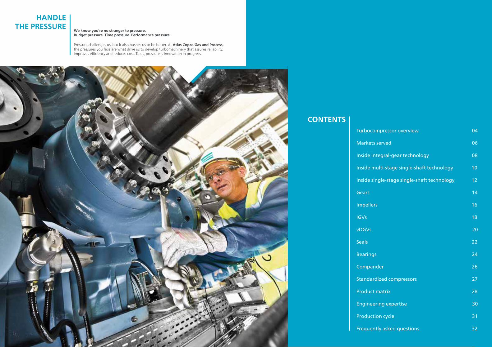
Single-shaft compressor benefits
• Maximum compressor efficiency and robustness in complex and rigid polyolefin processes
• Stable supply gas is critical for sustainable production• Prevention of polymerization in equipment• Smart plug-in design for maximum level of compressor
maintainability and improved availability of your overall plant• Compliance with codes and regulations including API 617,
API 614, ERC Russia, CSA/CRN
SINGLE-SHAFT COMPRESSORS – POLYBLOCKTM
With its proven design features and maintainability concepts, Atlas Copco Gas and Process T-series compressors are the right match for the challengingrequirements in your polyolefin plant.
Our smart plug-in design for direct-driven compressors enables easy access to all rotating parts such as dry face seals,impellers, bearings or vibration probes. For maintenance, the bearing carrier can be pulled from the back. In turn, this ensures a maximum level of compressor maintainability, and ultimately improves theavailability of your overall plant.
Proven maintainability concepts
SIMPLE CONCEPTS
FOR SUPERIORPROCESS
RELIABILITY Our single-shaft PolyBlockTM unlocks a high level of aerodynamic performance. The entire compressor stage is designed to prevent polymerization in the machine to ensure process reliability and availability.
Single shaftThe single-shaft direct-driven compressor's critical components, such as shaft seals and bearings, are anchored in proven, field-tested designs. The entire compressor stage is designed to prevent polymerization.
Inlet guide vanesCavity of IGVs are purged with clean dry gas to ensure smooth performance of IGVs and thus the entire compressor.
ImpellerDynamically balanced impellers with backward-leaning blades are tested for efficiency and balance.
SealsDry face seals enclose the rotor shaft – ideal for keeping process gas within the compressor, minimizing leakage and ensuring all available power is utilized.
1
4
3
2
5
42
3
1
BearingsShaft bearings are split-tilting type bearings with five pads per bearing. Babbitt-faced steel construction provides exceptional long life.
5

15Driving Centrifugal Compressor Technology14
GEARS:THE INTEGRAL
ADVANTAGE No other rotary compressor design can provide integrally gearedcompressors’ unmatched performance and customization. Integral gearingenables compressors to get the most from compression aerodynamics atevery stage – delivering superior efficiency and energy savings.
DESIGN FEATURES
Forged or hot-rolled alloy steel shafts
• One-piece pinion forgings• Forged bull gear, interference fit to shaft• Gear rating methodology differentiated by gear ratio:
– Below 7:1 - API 613 – Above 7:1 - AGMA 2101 / ISO 1940 modified for material and gear grinding quality to achieve reliability consistent with API 613
– Ratings based on twenty-year life and API service factor• Easy access for inspection and maintenance
GEARBOX TECHNICAL HIGHLIGHTS Performance without compromise
One of integral gearing’s main advantages is its flexibility. By running each stage group off an independent pinion and utilizing gear ratios between a main bull gear and pinions, each compression stages is individually set for optimal aerodynamics.
This means that the greatest amount of compression can be created for the least amount of energy.
At the same time, integral gearing offers a space-saving, compact footprint while still allowing easy access for inspection and maintenance.
• Four high-speed pinions (up to 8 stages) with optimum individual speed
• Multi- and combined service on the same gearbox• Can be combined with hot or cold gas turboexpander• Flexible drive options including electric motor,
steam or gas turbine• Simple accommodation of intercooling between each
of the stages• Compact footprint• Easy access for inspection and maintenance
INTEGRAL GEAR TECHNOLOGY BENEFITS
High power: booster air compressorSteel plant, China
Our largest main air compressor weighs 800 tons and has a powerful 29 MW drive (39 000 HP).
High RPMs: pipeline compressorNatural gas pipeline, Poland
Thanks to integral gearing, a pipeline sendout gas compressor produces pinion speeds of over 45 000 RPM.
Inlet pressure 0.99 bar (a) (14.4 psia)
Outlet pressure 6.4 bar (a) (92.8 psia)
Flow 380 000 m³/ h (220 000 cfm)
Inlet temperature 30 °C (86 °F)
Driver power 29 MW (39 000 hp)
Inlet pressure 6.3 bar (a) (91 psia)
Outlet pressure 38.9 bar (a) (564.2 psia)
Flow 2 516 m³/ h (1 480 cfm)
Inlet temperature 37.5 °C (99.5 °F)
Driver power 3 000 rpm
Max. machine speed 45 682 rpm
17Driving Centrifugal Compressor Technology16
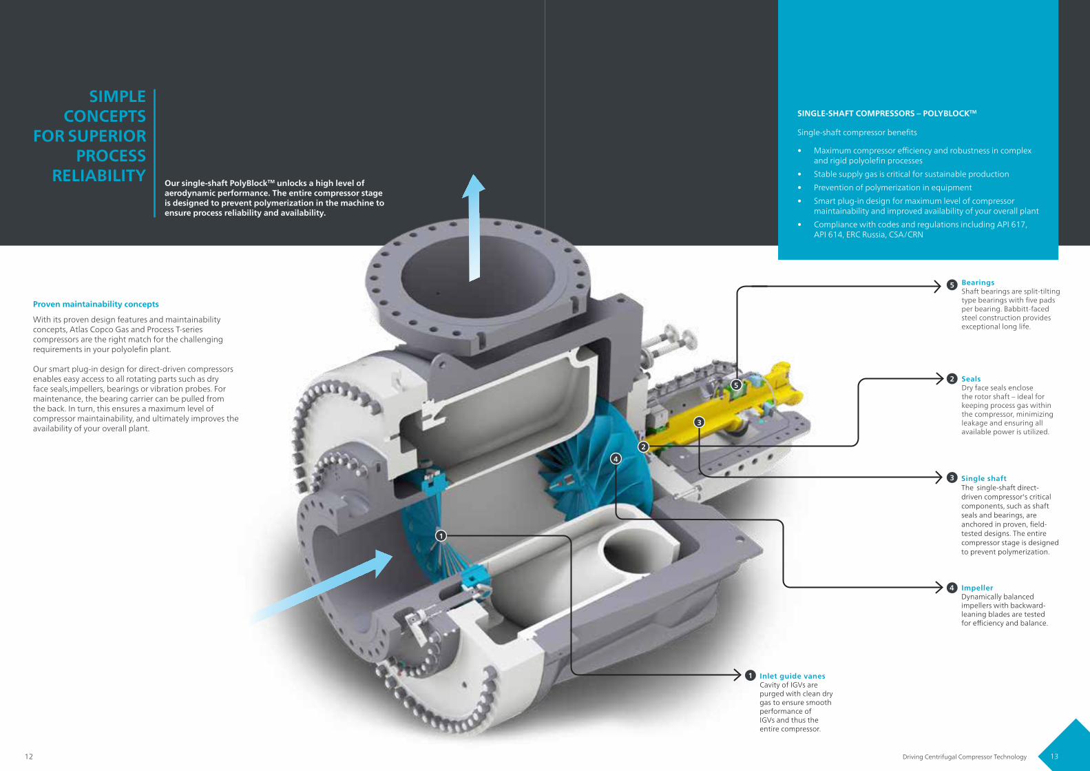
IMPELLERS:AERODYNAMICS
IN ACTION Impellers run at the heart of centrifugal compressors, creating both pressureand flow. Through the experience of building thousands of compressorstages and the latest computer design tools, Atlas Copco Gas and Processdelivers impellers to meet your exact flow and pressure requirements whileoffering high efficiency and a wide control range.
DESIGN FEATURES
A centrifugal compressor can only deliver high efficiency and a wide flow range if its impellers can. That is precisely where our experience comes into play. Over more than seven decades we’ve developed a vast database of impeller designs, and we have extensive knowledge in custom designs for specific gases and applications.
We use the latest computational-fluid dynamic (CFD) and finite-element analysis (FEA) to design our impellers and they are milled with the latest five-axis, computer-aided manufacturing processes.
Our performance-tested impellers include all standard 2D and 3D geometries in both shrouded and open configurations, reaching over 1.700 m.
Proven, efficient impeller designs
An aerodynamic impeller calculation in CFD
• Geometries include 45°, 50°, 65° and 90° in either open or closed configurations• Precision stainless steel or milled from solid forging, depending on application requirements• Standard material is X3CrNiMo (1.4313) or Armco 15-5 PH; other materials are Aluminium 2618 or Titanium 6061• A full range of 2D and 3D designs• Each impeller is dynamically balanced, as well as overspeedand ring tested before assembly• Closed impeller designs are produced as an integral single piece, precision welded, or via high temperature vacuum brazing
IMPELLER TECHNICAL HIGHLIGHTS
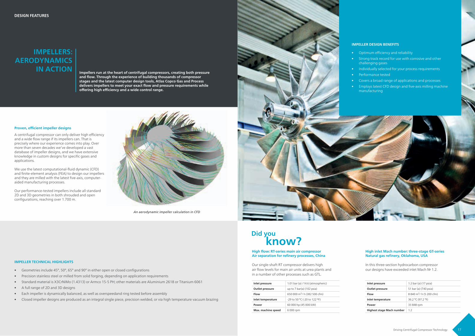
• Optimum efficiency and reliability• Strong track record for use with corrosive and other
challenging gases• Individually selected for your process requirements• Performance tested• Covers a broad range of applications and processes• Employs latest CFD design and five-axis milling machine
manufacturing
IMPELLER DESIGN BENEFITS
High flow: RT-series main air compressorAir separation for refinery processes, China
Our single-shaft RT compressor delivers highair flow levels for main air units at urea plants andin a number of other processes such as GTL.
High inlet Mach number: three-stage GT-seriesNatural gas refinery, Oklahoma, USA
In this three-section hydrocarbon compressorour designs have exceeded inlet Mach № 1.2.
Inlet pressure 1.01 bar (a) /14.6 (atmospheric)
Outlet pressure up to 7 bar(a) (102 psia)
Flow 650 000 m³/ h (382 500 cfm)
Inlet temperature -29 to 50 °C (-20 to 122 ºF)
Power 60 000 hp (45 000 kW)
Max. machine speed 6 000 rpm
Inlet pressure 1.2 bar (a) (17 psia)
Outlet pressure 51 bar (a) (740 psia)
Flow 8 840 m³/ h (5 200 cfm)
Inlet temperature 36.2 °C (97.2 °F)
Power 33 848 rpm
Highest stage Mach number 1.2

19Driving Centrifugal Compressor Technology18
IGVS:DELIVERING
SUPERIOR EFFICIENCY Variable inlet guide vanes (IGVs) are a proven option for centrifugal
compressors that can reduce energy use and give greater control over thecompressor’s operating range. They are part of a full range of capacity-controloptions that ensure your process is as flexible and efficient as possible.
DESIGN FEATURES
Energy consumption represents about 80% of a total compressor's lifecycle costs. So, energy savings can have a big result on the bottom line.
Inlet guide vanes help reduce these energy costs by creating an initial pre-swirl flow pattern that is matched to the impeller, improving compressor efficiency and reducing the amount of power required for compression. At the same time, they act as an efficient throttling device that ensures your compressor is delivering optimal performance during non-design point operation, typically the majority of a compressor’s service life.
They provide accurate process control and maintain efficient operation over a wide range of flow levels.
Complete process control through IGVs
0.3 0.4 0.5 0.6 0.7 0.8 0.9 1.0 1.1 1.2 1.3 1.4
RELATIVE VOLUME FLOW
RELA
TIVE
PRE
SSU
RE R
ATIO
1.4
1.2
1.0
0.8
0.6
0.4
-80º closed
0.950.90
20º openα=0º
nnA
=1.00.98
• A typical energy savings of 9% versus butterfly valves and other throttling methods
• Excellent partial load performance• Wide operating range, typcially 75% to 105% of design flow• Available on all stages for multistage compressors
• Avoids more pronounced pressure drops caused by suction throttling
• Perfect for applications that often operate below design point
BENEFITS OF VARIABLE INLET GUIDE VANES
Combined service: ammonia compressorFertilizer plant in the Netherlands
At a fertilizer plant, this machine compresses CO2over four stages and ammonia across two separatestages using one drive.
Two-stage FGB w/ IGVs and throttle valveOver 400 FGB units around the globe
This fuel gas booster incorporates IGV control withtwo throttle valves to operate over the large moleweight swing.
Inlet pressure (section one) 1.1 bar (a) (16 psia)
Inlet pressure (section two) 1.6 bar (a) (23.2 psia)
Outlet pressure (section one) 22 bar (a) (319 psia)
Outlet pressure (section two) 3.0 bar (a) (43.5 psia)
Flow (section one) 7 270 m³/ h (4 279 cfm)
Flow (section two) 2 810 m³/ h (1 654 cfm)
Power consumption 1.5 MW (2 000 hp)
Inlet pressure 10 bar (a) (145 psia)
Outlet pressure 36 bar (a) (522.1 psia)
Flow 59 508 kg/ h (131 192.5 lb/h)
Inlet temperature 12.7 – 47°C (54.9 – 116.6°F)
Power 3 780 – 4 270 kW (5 070 – 5 726 hp)
21Driving Centrifugal Compressor Technology20
vDGVS: KEEPING THE
PRESSURECONSTANT
WITH LARGER TURNDOWN
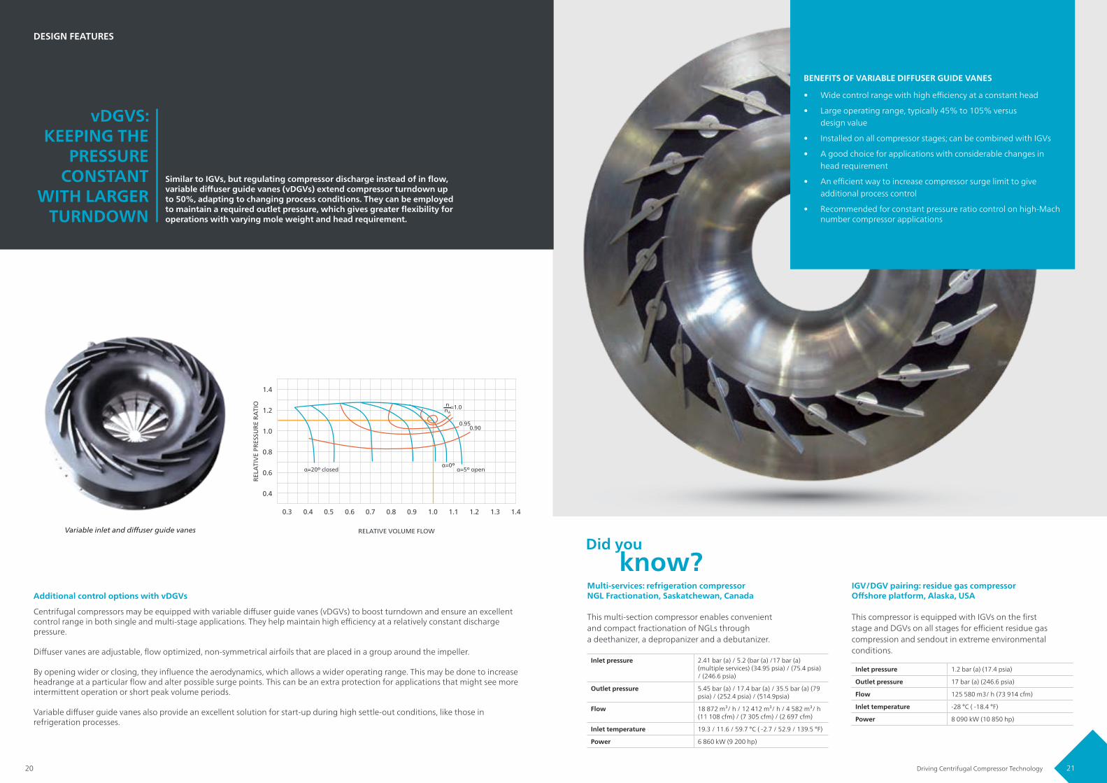
Similar to IGVs, but regulating compressor discharge instead of in flow,variable diffuser guide vanes (vDGVs) extend compressor turndown up to 50%, adapting to changing process conditions. They can be employed to maintain a required outlet pressure, which gives greater flexibility for operations with varying mole weight and head requirement.
DESIGN FEATURES
Centrifugal compressors may be equipped with variable diffuser guide vanes (vDGVs) to boost turndown and ensure an excellent control range in both single and multi-stage applications. They help maintain high efficiency at a relatively constant discharge pressure.
Diffuser vanes are adjustable, flow optimized, non-symmetrical airfoils that are placed in a group around the impeller.
By opening wider or closing, they influence the aerodynamics, which allows a wider operating range. This may be done to increase headrange at a particular flow and alter possible surge points. This can be an extra protection for applications that might see more intermittent operation or short peak volume periods.
Variable diffuser guide vanes also provide an excellent solution for start-up during high settle-out conditions, like those in refrigeration processes.
Additional control options with vDGVs
• Wide control range with high efficiency at a constant head
• Large operating range, typically 45% to 105% versus design value
• Installed on all compressor stages; can be combined with IGVs
• A good choice for applications with considerable changes in head requirement
• An efficient way to increase compressor surge limit to give additional process control
• Recommended for constant pressure ratio control on high-Mach number compressor applications
BENEFITS OF VARIABLE DIFFUSER GUIDE VANES
Variable inlet and diffuser guide vanes
0.3 0.4 0.5 0.6 0.7 0.8 0.9 1.0 1.1 1.2 1.3 1.4
RELATIVE VOLUME FLOW
RELA
TIVE
PRE
SSU
RE R
ATIO
1.4
1.2
1.0
0.8
0.6
0.4
α=20º closed
0.950.90
α=5º openα=0º
nnA
=1.0
Multi-services: refrigeration compressorNGL Fractionation, Saskatchewan, Canada
This multi-section compressor enables convenientand compact fractionation of NGLs througha deethanizer, a depropanizer and a debutanizer.
IGV/DGV pairing: residue gas compressorOffshore platform, Alaska, USA
This compressor is equipped with IGVs on the firststage and DGVs on all stages for efficient residue gas compression and sendout in extreme environmental conditions.
Inlet pressure 2.41 bar (a) / 5.2 (bar (a) /17 bar (a) (multiple services) (34.95 psia) / (75.4 psia) / (246.6 psia)
Outlet pressure 5.45 bar (a) / 17.4 bar (a) / 35.5 bar (a) (79 psia) / (252.4 psia) / (514.9psia)
Flow 18 872 m³/ h / 12 412 m³/ h / 4 582 m³/ h (11 108 cfm) / (7 305 cfm) / (2 697 cfm)
Inlet temperature 19.3 / 11.6 / 59.7 °C ( -2.7 / 52.9 / 139.5 °F)
Power 6 860 kW (9 200 hp)
Inlet pressure 1.2 bar (a) (17.4 psia)
Outlet pressure 17 bar (a) (246.6 psia)
Flow 125 580 m3/ h (73 914 cfm)
Inlet temperature -28 °C ( -18.4 °F)
Power 8 090 kW (10 850 hp)

23Driving Centrifugal Compressor Technology22
SEALS: MINIMIZING LEAKAGE TO
KEEP PROCESS GAS WITHIN THE SYSTEM
For challenging expensive, corrosive, or toxic process gases, leakage is notan option. Our compressors are available with a range of state-of-the-artseals. Because every application requires a different solution, we offer a widevariety of seals with options matched precisely to your specific requirements.
DESIGN FEATURES
Our sealing options include dry gas, floating carbon ring, and labyrinth seals. All are designed to provide one universal advantage: process safety.
Drawing on decades of engineering experience, our experts will gladly help you identify the seal type that meets your precise process needs.
The perfect fit for your application
• Minimize or eliminate gas leakage
• Superior reliability
• Options include: dry-gas, floating carbon ring, oil-lubricated and labyrinth seals
• Referenced over wide range of applications, gas mixtures and pressures
• Solutions for extreme temperatures, and corrosive, toxic and/or flammable gases
• Full compliance with API 614/617
• Wide experience with various buffer gases
SEAL SOLUTION BENEFITS
When extreme process conditions might prohibit the use of an alternative sealing method – especially with cryogenic or hot gases – our carbon ring seal solutions present a cost-effective and reliable solution.
We can combine carbon rings seals with two to five chambers for buffer gas and they may be used as a primary or process seal. They can also be employed as tertiary seals or barrier seals to prevent lube oil contamination into secondary seals.
Whether you are dealing with a flammable gas mixture, high-pressure CO2 or a toxic cyanide, process gas needs to remain in the machine. It is not only important for plant safety, it can influence process efficiency and performance. Our dry gas seals are justthe answer.
They can be applied in single, tandem or double configurations for absolute tightness. The seals meet the API 614/617 standard, and are referenced over wide range of applications, gases and pressures.
Dry gas seals virtually eliminate gas leakage
Carbon ring seals for harshest conditions
Carbon ring seal
Dry gas seal
Dry gas seals – toxic gas mixturesGasification vent gas blower, India
This compressor uses double dry-gas seals as thebuffer to ensure that the mixture of air with traces oftoxic hydrogen cyanide (HCN) stays within the system.
Carbon ring seals – lowest temperaturesLNG facility, western Australia
This compressor at a LNG plant in western Australiahas one of the lowest inlet temperatures of all ourcompressor references.
Inlet pressure 1.03 bar (a) (14.94 psia)
Outlet pressure 2.48 bar (a) (36 psia)
Flow 51 788 kg/ h (114 173 lbs/ h)
Inlet temperature -160 °C (-256 °F)
Power 1 180 kW (1 582 hp)
Inlet pressure 0.935 bar (a) (13.56 psia)
Outlet pressure 1.62 bar (a) (23.50 psia)
Flow 34 420 kg/ h (75 880 lbs/ h)
Inlet temperature 37 °C (99 °F)
Outlet temperature 102 °C (216 °F)
Power 750 kw (1 006 hp)

25Driving Centrifugal Compressor Technology24
BEARINGS: ENSURING
ROTOR STABILITY
AND RELIABILITY
Integral gearing delivers the optimal aerodynamics that give our compressors their highest possible efficiency. Perfectly matched bearings enhance this performance by providing best stability to high-speed rotors as well as main drive shaft. These bearings offer excellent anti-vibration and stability characteristics, while enabling easy inspection and maintenance.
DESIGN FEATURES
The bull gear shaft, the main driver of the gearbox, is supported by multi-lobe sleeve bearings. One of these bearings is a combination of radial and thrust bearing with tapered land-thrust faces that allow rotation in either direction.
High-speed rotors are also supported by radial tilting pad bearings that are designed to compensate for their net thrust forces. These bearing reduce virtually all vibration and provide superior stability.
Oil supplied via nozzles (inside the bearings and close to the pads) ensures a consistent oil film as soon as rotation starts. This also minimizes oil use while keeping bearing pad temperatures low.
Lower-speed rotors often use sleeve bearings.
Meticulous engineering of all rotating parts, means friction, vibration and mechanical losses are kept to a minimum.
Keeping everything spinning
• Specially engineered bearing designs for long life and exceptional reliability
• Eliminate virtually all vibrations and provide superior operating stability
• Thrust collars to reduce friction and minimize mechanical losses
• Horizontally split bearings allow easy inspection and maintenance
• Directed lubrication nozzles keep bearing pad temperatures low
• Bearings take into account oppositional forces created through compression and gearing
BEARINGS BENEFITS
Tilting pad axial bearing (combi bearing) Tilting pad journal (lateral) bearing
CO2 compressor with specially designed bearingsUrea fertilizer plant, Russia
This CO2 compressor uses squeeze film damperbearings to compensate for cross-coupling betweenrotor vibration and gas flow.
CO2 compressor for Supercritical CO2 Power CycleGas turbine driven compressor for sCO2
This compressor provides high-pressure CO2 to one of thefirsts CO2 Allam Cycle power generation plants for efficientpower and minimal emissions.
Inlet pressure 25.3 bar (a) (367 psia)
Outlet pressure 90 bar (a) (1 305 psia)
Flow 334 300 kg/ h (737 000 lbs/h)
Inlet temperature 34 °C (93 °F)
Notable technology
Variable IGVs for potentialturndown up to 35%;intercoolers to further reducepower consumption
Inlet pressure Atmospheric
Outlet pressure 205 bar (a) (2 973 psia)
Flow 18 000 Nm3/ h (10 594 scfm)
Inlet temperature 161 °C (322 °F)
BearingsHorizontally split squeeze filmhigh-dampening bearings; axial thrustbearings in higher stages
27Driving Centrifugal Compressor Technology26
BRIDGING TECHNOLOGIES:
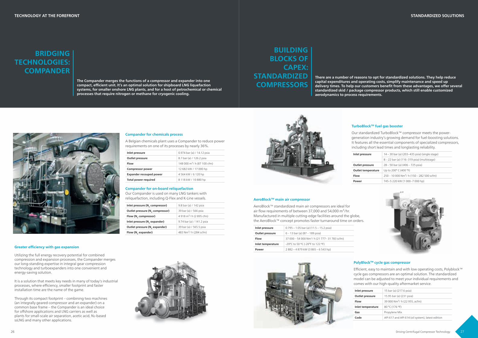
COMPANDERThe Compander merges the functions of a compressor and expander into one compact, efficient unit. It’s an optimal solution for shipboard LNG liquefaction systems, for smaller onshore LNG plants, and for a host of petrochemical or chemical processes that require nitrogen or methane for cryogenic cooling.
BUILDING BLOCKS OF
CAPEX:STANDARDIZED COMPRESSORS
There are a number of reasons to opt for standardized solutions. They help reduce capital expenditures and operating costs, simplify maintenance and speed up delivery times. To help our customers benefit from these advantages, we offer several standardized skid / package compressor products, which still enable customized aerodynamics to process requirements.
TECHNOLOGY AT THE FOREFRONT STANDARDIZED SOLUTIONS
Compander for chemicals process
A Belgian chemicals plant uses a Compander to reduce power requirements on one of its processes by nearly 36%.
TurboBlockTM fuel gas booster
Our standardized TurboBlock™ compressor meets the power-generation industry’s growing demand for fuel-boosting solutions. It features all the essential components of specialized compressors, including short lead times and longlasting reliability.
PolyBlockTM cycle gas compressor
Efficient, easy to maintain and with low operating costs, Polyblock™ cycle gas compressors are an optimal solution. The standardized model can be adjusted to meet your individual requirements andcomes with our high-quality aftermarket service.
AeroBlockTM main air compressor
AeroBlock™ standardized main air compressors are ideal for air flow requirements of between 37,000 and 54,000 m³/hr. Manufactured in multiple cutting-edge facilities around the globe, the AeroBlock™ concept promotes faster turnaround time on orders.
Compander for on-board reliquefactionOur Compander is used on many LNG tankers with reliquefaction, including Q-Flex and K-Line vessels.
Utilizing the full energy recovery potential for combinedcompression and expansion processes, the Compander merges our long-standing expertise in integral gear compressiontechnology and turboexpanders into one convenient andenergy-saving solution.
It is a solution that meets key needs in many of today's industrial processes, where efficiency, smaller footprint and faster installation time are the name of the game.
Through its compact footprint – combining two machines (an integrally geared compressor and an expander) on a common base frame – the Compander is an ideal choicefor offshore applications and LNG carriers as well asplants for small-scale air separation, acetic acid, N2-basedssLNG and many other applications.
Greater efficiency with gas expansion
Inlet pressure 14 – 30 bar (a) (203–435 psia) (single stage)
8 – 22 bar (a) (116–319 psia) (multistage)
Outlet pressure 28 – 50 bar (a) (406 – 725 psia)
Outlet temperature Up to 200° C (400 °F)
Flow 250 – 10 000 Nm³/ h (150 – 282 500 scfm)
Power 745–5 220 kW (1 000–7 000 hp)
Inlet pressure 0.795 – 1.05 bar (a) (11.5 – 15.2 psia)
Outlet pressure 6 – 13 bar (a) (87 – 189 psia)
Flow 37 000 – 54 000 Nm3/ h (21 777– 31 783 scfm)
Inlet temperature -29°C to 50 ºC (-20°F to 122 ºF)
Power 2 882 – 4 879 kW (3 865 – 6 543 hp)
Inlet pressure 15 bar (a) (217.6 psia)
Outlet pressure 15.95 bar (a) (231 psia)
Flow 39 000 Nm³/ h (22 955, acfm)
Inlet temperature 80 °C (176 ºF)
Gas Propylene Mix
Code API 617 and API 614 (oil system), latest edition
Inlet pressure (N2 compressor) 9.8 bar (a) / 142 psia
Outlet pressure (N2 compressor) 39 bar (a) / 566 psia
Flow (N2 compressor) 4 918 m³/ h (2 895 cfm)
Inlet pressure (N2 expander) 9.74 bar (a) / 141.2 psia
Outlet pressure (N2 expander) 39 bar (a) / 565.5 psia
Flow (N2 expander) 483 Nm³/ h (284 scfm)
Inlet pressure 0.974 bar (a) / 14.12 psia
Outlet pressure 8.7 bar (a) / 126.2 psia
Flow 148 000 m³/ h (87 100 cfm)
Compressor power 12 682 kW / 17 000 hp
Expander recouped power 4 564 kW / 6 120 hp
Total power required 8 118 kW / 10 880 hp
29Driving Centrifugal Compressor Technology28
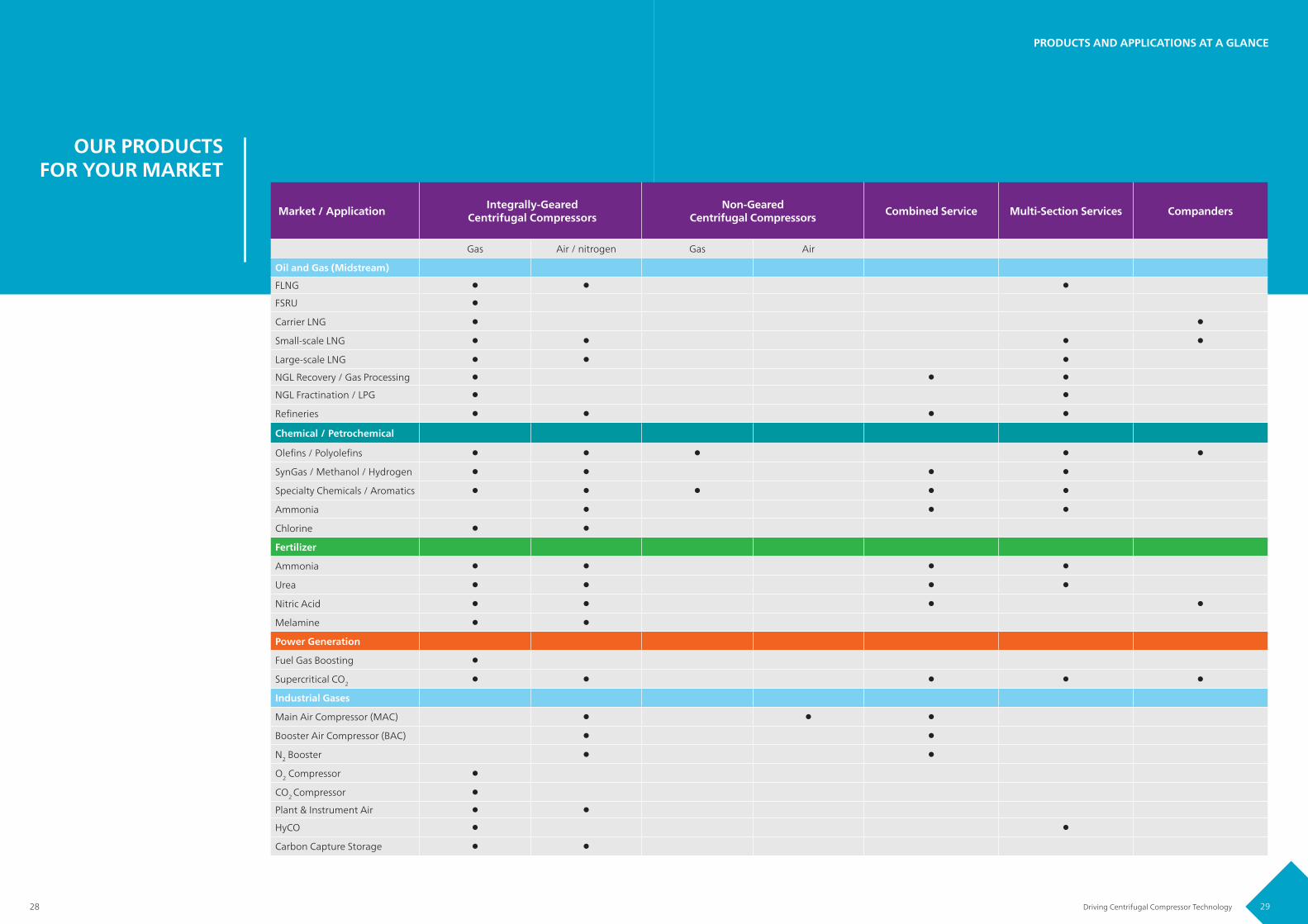
OUR PRODUCTS FOR YOUR MARKET
PRODUCTS AND APPLICATIONS AT A GLANCE
Market / Application Integrally-Geared Centrifugal Compressors
Non-Geared Centrifugal Compressors Combined Service Multi-Section Services Companders
Gas Air / nitrogen Gas Air
Oil and Gas (Midstream)
FLNG
FSRU
Carrier LNG
Small-scale LNG
Large-scale LNG
NGL Recovery / Gas Processing
NGL Fractination / LPG
Refineries
Chemical / Petrochemical
Olefins / Polyolefins
SynGas / Methanol / Hydrogen
Specialty Chemicals / Aromatics
Ammonia
Chlorine
Fertilizer
Ammonia
Urea
Nitric Acid
Melamine
Power Generation
Fuel Gas Boosting
Supercritical CO2
Industrial Gases
Main Air Compressor (MAC)
Booster Air Compressor (BAC)
N2 Booster
O2 Compressor
CO2 Compressor
Plant & Instrument Air
HyCO
Carbon Capture Storage

31Driving Centrifugal Compressor Technology30
ENGINEERING KNOWLEDGE
AT YOUR SERVICE
At Atlas Copco Gas and Process, we know that building the very best compressors takes extensive expertise, state-of-the-art tools and dedicated engineers. Our commitment to excellence puts us in close contact with customers around the world, as we follow our compressors from initial design and testing through their long lifecycles.
COVERING THE ENTIRE
COMPRESSORPRODUCTION
CYCLE From milling, spinning and balancing to instrumentation and piping assembly, success in the turbomachinery business is built on exacting tolerances. We look to each and every detail with specific goals in mind: ensuring your efficiency and productivity over the long term.
PRODUCTION, DESIGN AND TEST
Our engineering department sets standards in the areas of aerodynamics, rotor design, controlling technology, lubrication systems, pressure vessels and more.
Our specialists are backed by the latest software and design technology in aerodynamics, mechanics and package engineering.
Proven engineering expertise
Aerodynamics Mechanics Design
• OEM software• Experimental measurements• CFD analysis: ANSYS• Gas programs: HYSYS, REFPROF,
NIST, GPA, PR, SRK, FRG
• OEM software• Rotor dynamics: SR3• Rotor dynamics & bearings: Madyn• Torsional analysis: DRESP• FEA: ANSYS• FVA workbench: RICOR, ST-Plus
• 3D-CAD: Creo, MEDUSA / MPDS, Autodesk, Inventor, Solid Works
• 2D-CAD: MEDUSA• Process design: HYSYS• Component design: OEM software
High-speed rotor balancing machines
Impeller overspeed pit
Inside the 5-axis machine: the milling process
Long-term investments in machinery and infrastructure ensure we maintain the highest standards. This means we have the most up-to-date, cutting-edge production facilities to carry out our work. Working with the appropriate tools and processes, we use our extensive engineering expertise to create innovative, best-in-class products. And we will continue to invest in machinery and in the skills of our highly skilled employees.
We rely on the best state-of-the-art production machinery for our components, which includes, milling, balancing and spinning equipment, for example. Moreover, we have a thoroughly modern production infrastructure that compares with anything across the globe, which provides the basis for fulfilling all your process needs. To back this up, we carry out constant product-performance reviews, and provide robust and strict quality assurances.
Quality in every area of our production and maintenance is key to the way we work. This means that not only do we do the packaging locally, but we source peripheral components for best quality and delivery. In addition, we package all key components in-house, and this ensures premium quality as well as meaning we can maintain our delivery times. If you order from us, we enter into a long-term commitment to deliver the right service for you.
Inside our production facilities
In-house capabilities

33Driving Centrifugal Compressor Technology32
FREQUENTLY ASKED
QUESTIONS Here are some of the most frequently asked questions we receive about turbomachinery, test and quality standards we comply with, as well as manufacturing process, packaging, testing facilities and aftermarket support. Feel free to reach out to us with specific queries.
PRODUCTION, DESIGN AND TEST
What pre-delivery testing is offered forcentrifugal compressors?
What international specifications and standards do your compressors meet?
As a standard quality assurance measure, all compressors are mechanically tested prior to shipment. We have the ability to simulate mostoperating conditions you might face, so yourcompressor is not only ready to perform from thestart but to continue this over its long service life.A full range of performance testing is availableupon request.
Our facilities have complete test beds and we canundertake all tests for full compliance with allmajor relevant standards, including DIN, ISO, VDI2045, ASME, PTC 10 and API 617/672. We workclosely with our customers in order to achieve ourfinal goal: delivering the best product possible.
We manufacture compressors to meet therigorous standards set out by the AmericanPetroleum Institute (API). This applies to gears,lube oil supply, rotor dynamic options and more.
Our compressors can meet API 617, Chapter 3(gas) and API 672 (air) requirements, includingoil systems that reflect API 614. We can also meet all major international, national, as well as manufacturer and end-user standards. This includes the ISO 11011 and ISO/TC 118/SC 1standards, DIN, ASME Standard EA-4-2008,CENELEC and many others.
Ultimately, it’s about making sure we providethe quality, efficiency, and sustainability youneed to carry out your processes.
What aftermarket support do you provide?
Our global aftermarket services network consists of 7 service centers and 130+ sales engineers, protecting your machinery for a lifetime of sustainable productivity. The services range from on-site erection and commissioning to breakdown and repair.
Our expert engineers will be with you every stepof the way to ensure that your plant and productivity remain functioning at the mostoptimal level. Our service plan, for example,comes with a fixed-rate maintenance program;preventative maintenance maximizes uptime,
helps avoid productivity downtime and providesproactive inspections; and when you need replacement parts, you will always receivegenuine parts, backed up with our lifetimemanufacturer guarantee.
Our production and testing are always carried outin-house by our expert personnel, which meansthat we guarantee the quality of every component at every stage. With our comprehensive aftermarket services, we provide you with tailor-made support to maintain your production as smoothly as possible.
Turbomachinery and test standards Our aftermarket services
• DIN• VDI 2045• ASME• PTC 10
• API 617, Chapter 3 (gas)• API 672 (air)• API 614• ISO 11011• ISO / TC 118/SC 1• EA-4-2008, CENELEC• and many more
• Genuine parts• Breakdown & repair• Preventive maintenance• Service plan• Redesign & upgrades• All-brand services• Advanced services

35Driving Centrifugal Compressor Technology34
FREQUENTLY ASKED
QUESTIONS From building our products to precise specifications through packaging options and extensive testing, our aim is to ensure Atlas Copco Gas and Process compressors are ready for your process from day one. Feel free to reach out to us with specific queries.
PRODUCTION, DESIGN AND TEST
What type of packaging options are available?Does Atlas Copco Gas and Process package according to API?
What quality compliance do you guarantee? What are your quality benchmarks?
First, our growing number of standardizedproducts are often delivered fully-packaged andready for quick set-up. Our customizedcompressors are available in full-packaging,semi-packaging and free arrangement options.All but our very largest compressors can be builtand transported in full or semi-packaging options.
Free arrangement enables our customers to take advantage of possibilities to locally source components – such as piping and cooling.
We are able to handle all relevant packaging tomeet API and other major specifications. This caninclude highly specified packaging solutions.In-house manufacturing and packaging centers throughout the world in Germany, California, New York, China and India, as well as numerous service centers, keep packaging close to customers.
Our focus on quality means that all of ourequipment is designed and constructed for a minimum service life of 20 years and at least three years of uninterrupted operation.
Because we’re active in numerous markets, we also adhere to a range of standards, including ISO, ASME, DIN, and CENELEC. This includes national and regional standards (such as those used in Australia, Russia and Japan), as well as the Marine Standard.
Finally, all our global facilities are subject to quality assurance programs certified to the ISO 9001 standard and registered by Lloyds Register Quality Assurance, Ltd. We are registered facilities for the following integrated management systems: ISO14000 (environmental), ISO9001 (quality), ISO50001 (energy), and OHSAS 18001 / ISO45001 (safety).
B26/
004/
036/
0618
© A
tlas C
opco
Gas
and
Pro
cess
02/
2019
Prin
ted
in G
erm
any.
Atlas Copco Gas and Process Schlehenweg 15, 50999 Cologne, GermanyPhone: +49 2236 96 50 0www.atlascopco-gap.com
Top Related