


Languages
Pages
Legal


Product Catalogue
Draka | Energy & Infrastructure | Draka Keila Cables

Environment and quality policy
Draka Keila Cables Ltd wishes to gain satisfaction
of the customers, employees and owners without
damaging of environment. In Draka Keila Cables
the decisions are made, which allow to develop the
company and to save environment at the same time
and on the assumption of this principle continuously
to improve the system of management.
In Draka Keila Cables Ltd there is used the multistage
program of the quality control, which covers
production process from development of the cables,
purchasing of raw materials and production of
installation and power cables to the documentation
of supplemental examinations and tests.
The quality and environmental manageme nt
system of Draka Keila Cables Ltd has appraised and
approved by Lloyd’s Register Quality Assurance
Limited, which performs regular audits according to
standard of quality system ISO 9001 and ISO 14001.

Table of ContentsIntroduction . . . . . . . . . . . . . . . . . . . . . . . . . . . . . . . .2
General information . . . . . . . . . . . . . . . . . . . . . . . . . .3
Basic cable data . . . . . . . . . . . . . . . . . . . . . . . . . . . . .3
Power cables
ACSR . . . . . . . . . . . . . . . . . . . . . . . . . . . . . . . . . . . . . 8
HK . . . . . . . . . . . . . . . . . . . . . . . . . . . . . . . . . . . . . . . . 10
AS . . . . . . . . . . . . . . . . . . . . . . . . . . . . . . . . . . . . . . . . 11
A . . . . . . . . . . . . . . . . . . . . . . . . . . . . . . . . . . . . . . . . . 12
AXMK & XMK 1-core . . . . . . . . . . . . . . . . . . . . . . . . . 13
AXPK . . . . . . . . . . . . . . . . . . . . . . . . . . . . . . . . . . . . . 14
EMC-Line 1kV (IFSI) . . . . . . . . . . . . . . . . . . . . . . . . . 16
EMC-Line 1kV (IFSI) . . . . . . . . . . . . . . . . . . . . . . . . . 17
AMCMK 3 1/2-core . . . . . . . . . . . . . . . . . . . . . . . . . . 18
AMCMK 4 1/2-core . . . . . . . . . . . . . . . . . . . . . . . . . 20
MCMK 3-core . . . . . . . . . . . . . . . . . . . . . . . . . . . . . . 22
MCMK 4-core. . . . . . . . . . . . . . . . . . . . . . . . . . . . . . 23
MCMK 5-core . . . . . . . . . . . . . . . . . . . . . . . . . . . . . . 24
MCCMK 4-core . . . . . . . . . . . . . . . . . . . . . . . . . . . . 26
MCCMK 5-core . . . . . . . . . . . . . . . . . . . . . . . . . . . . .27
MCMK 3 1/2-core . . . . . . . . . . . . . . . . . . . . . . . . . . . 28
MCMK 4 1/2-core. . . . . . . . . . . . . . . . . . . . . . . . . . . 30
MCMO . . . . . . . . . . . . . . . . . . . . . . . . . . . . . . . . . . . . 32
EX . . . . . . . . . . . . . . . . . . . . . . . . . . . . . . . . . . . . . . . 33
AMKA . . . . . . . . . . . . . . . . . . . . . . . . . . . . . . . . . . . . 34
AHXAMK-W 6/10 (12) kV . . . . . . . . . . . . . . . . . . . . 35
AHXAMK-W 12/20 (24) kV . . . . . . . . . . . . . . . . . . . 36
AXLJ-TT 7/12 kV . . . . . . . . . . . . . . . . . . . . . . . . . . . .37
AXLJ-TT 14/24 kV . . . . . . . . . . . . . . . . . . . . . . . . . . 38
AXLJ-TTCL TSLF 14/24 kV . . . . . . . . . . . . . . . . . . 39
AXLJ-TT 7/12 kV (3-core) . . . . . . . . . . . . . . . . . . . . 40
AXLJ-TT 14/24 kV (3-core) . . . . . . . . . . . . . . . . . . . 41
AXLJ-RMF 7/12 kV . . . . . . . . . . . . . . . . . . . . . . . . . 42
AXLJ-RMF 14/24 kV . . . . . . . . . . . . . . . . . . . . . . . . 43
AXQJ-RMF 7/12 kV . . . . . . . . . . . . . . . . . . . . . . . . . 44
AXQJ-RMF 14/24 kV . . . . . . . . . . . . . . . . . . . . . . . . 45
AXQJ-F 7/12 kV . . . . . . . . . . . . . . . . . . . . . . . . . . . . 46
AXQJ-F 14/24 kV . . . . . . . . . . . . . . . . . . . . . . . . . . 47
PAS-W 20 kV . . . . . . . . . . . . . . . . . . . . . . . . . . . . . . 48
Installation cables and wires
PL / ML / H07V-U . . . . . . . . . . . . . . . . . . . . . . . . . . 49
PK / MK / H07V-R . . . . . . . . . . . . . . . . . . . . . . . . . 50
MK 90 / H07V2-R . . . . . . . . . . . . . . . . . . . . . . . . . . . 51
MKEM 90 / H07V2-K . . . . . . . . . . . . . . . . . . . . . . . 52
PPO / MMO . . . . . . . . . . . . . . . . . . . . . . . . . . . . . . . 53
EKLK 450/750 V . . . . . . . . . . . . . . . . . . . . . . . . . . 54
PPJ . . . . . . . . . . . . . . . . . . . . . . . . . . . . . . . . . . . . . . 55
MSK / H05VV-F . . . . . . . . . . . . . . . . . . . . . . . . . . . 57
MSO / H03VVH2-F . . . . . . . . . . . . . . . . . . . . . . . . . 58
MSOY / H03VV-F . . . . . . . . . . . . . . . . . . . . . . . . . . 59
PROFIT . . . . . . . . . . . . . . . . . . . . . . . . . . . . . . . . . . . 60
Automation, data and telecommunication cables
JAMAK . . . . . . . . . . . . . . . . . . . . . . . . . . . . . . . . . . . . 61
JAMAK ARM . . . . . . . . . . . . . . . . . . . . . . . . . . . . . . 62
NOMAK. . . . . . . . . . . . . . . . . . . . . . . . . . . . . . . . . . . 63
KLM. . . . . . . . . . . . . . . . . . . . . . . . . . . . . . . . . . . . . . 64
KLMA . . . . . . . . . . . . . . . . . . . . . . . . . . . . . . . . . . . . 65
LONAK . . . . . . . . . . . . . . . . . . . . . . . . . . . . . . . . . . . 66
PULS 2,5 75V . . . . . . . . . . . . . . . . . . . . . . . . . . . . . 67
MHS . . . . . . . . . . . . . . . . . . . . . . . . . . . . . . . . . . . . . 68
VMOHBU . . . . . . . . . . . . . . . . . . . . . . . . . . . . . . . . . 69
H05RN-F; RDO/05RN-F 300/500 V . . . . . . . . . . 70
DRAKAFLEX H07RN-F 450/750 V . . . . . . . . . . . . 71
DRAKAFLEX H07RN-F 450/750 V . . . . . . . . . . . .72
Halogen-fee and fire resistant cables
HULT(FLEX) LSOH 0,6/1kV . . . . . . . . . . . . . . . . . . .73
HULT(FLEX) LSOH FB30/60 0,6/1kV . . . . . . . . . .74
BI(c) 250V . . . . . . . . . . . . . . . . . . . . . . . . . . . . . . . . 75
BFSI-EMC 1kV . . . . . . . . . . . . . . . . . . . . . . . . . . . . . .76
HULT(FLEX) LSOH FB 90 0,6/1kV . . . . . . . . . . . .77
TI(c) 1000V . . . . . . . . . . . . . . . . . . . . . . . . . . . . . . . 78
TI(c) 1000V . . . . . . . . . . . . . . . . . . . . . . . . . . . . . . . 79
IXXI 1kV . . . . . . . . . . . . . . . . . . . . . . . . . . . . . . . . . . 80
EQLQ 450/750 V . . . . . . . . . . . . . . . . . . . . . . . . . . . 81
FQLQ 450/750 V . . . . . . . . . . . . . . . . . . . . . . . . . . 82
AXQJ 0,6/1 kV . . . . . . . . . . . . . . . . . . . . . . . . . . . . . 83
EXQJ 0,6/1 kV . . . . . . . . . . . . . . . . . . . . . . . . . . . . . 84
FXQJ 0,6/1 kV . . . . . . . . . . . . . . . . . . . . . . . . . . . . . 85
Drums
Drum handling guide . . . . . . . . . . . . . . . . . . . . . . . 86
Dimensions and weights . . . . . . . . . . . . . . . . . . . . 88
PRODUCT CATALOQUEDRAKA KEILA CABLES

IntroductionDraka Keila Cables was established in 1992. Company’s equity holders are Draka NK Cables Ltd. (former Nokia Cables), with 66%, and an Estonian electrical equip-ment producing company AS Harju Elekter with 34%.
Through Draka NK Cables Keila Kaabel belongs to DRA-KA Holding, one of the biggest cable producers in the world. The group consists of 59 entities located in 24 countries in Europe, Americas and Asia.
The headquarter and manufacturing facilities of Draka Keila Cables are located on territory of AS Harju Ele-kter in Keila, Estonia. Our major markets are Baltic countries. Representative offices have been set up in Riga and Vilnius to ensure proper communication with our customers in Latvia and Lithuania.
Draka Keila Cables is focused on the three main prod-uct groups: low-voltage and special purpose cables, power cables and telecommunication cables. Our
goal is to provide customers the best solutions for transmission of energy and information. Cables are produced in a wide range, according to needs of cus-tomers and current standards. Products are certified in internationally recognized certification authority SGS-FIMKO.
The quality of our products is assured by modern tech-nology, high-quality raw material and well-trained pro-fessionals. Company’s quality management system was declared to be in accordance with of ISO 9001 by LRQA in 1998. In 2001 Keila Kaabel environmental manage-ment system acquired certificate of accordance with the requirements of ISO 14 001.
Draka Keila Cables is a fast growing manufacturing company, the key to our success is ability to respond flexibly to rapidly changing business environment. Dra-ka Keila Cables is open for co-operation possibilities coming from east as well as west.
2 DRAKA KEILA CABLES PRODUCT CATALOQUE

General informationStandards
All conductors and cables in this catalogue are manufactured according to valid international standards. The cable meets the requirements of the standards mentioned in the cable description.
Special conductors and cables
Also other types of conductors and cables, not included in this cata-logue, are available by Draka, as agreed with the client.
Catalogue information
The dimensions and weights are nominal values. Due to continu-ous product research and development the listed data is subject to change. Our product development is a continuous process. We reserve the right to change the datas without prior notice.
Rated voltage
The table below gives the common rated voltage for cables accord-ing to the international standard IEC 38.
U0 rated voltage between the conductor and the earthU rated voltage between conductorsUm maximum operating voltage in any part of the network,
excluding temporary fluctuations during switching, breaking and faults
Up peak value of the impulse withstand voltage between each conductor and the earth
Basic cable dataMinimaalne painderaadius
• Minimum permissible bending radii during cable pulling aregiven in Basic cable data.
• Valuesmaybereducedbyabout30%inthefinalinstallation,ifthe cables are bent carefully and evenly only once.
Maximum pulling force
• Maximumpermissiblepullingtensionwhenpullingbythecablegrip is given in the basic data on each cable type
– cables with aluminium conductors . . . . . . . . . . 10 to 15 N/mm2
– cables with copper conductors . . . . . . . . . . . . 10 to 20 N/mm2 multiplied by the added-up cross section of the inner conduc-
tors, but max. value in both cases is 8,500 N.
•Pullingbytheeyeattachedtotheconductor
– cables with aluminium conductors . . . . . . . . . . . . . . 50 N/mm2
– cables with copper conductors . . . . . . . . . . . . . . . . 100 N/mm2
however not more than about 20,000 N.
• Pulling by the armouring wires 130 N/mm2, multiplied by the cross section of the armouringMINIMAALSED LUBATUD TEM-PERATUURID PAIGALDAMISEL
U0/U kV 0,6/1 3,6/6 6/10 12/20 18/30
Um kV 1,2 7,2 12 24 36
Up kV - - 75 125 170
3PRODUCT CATALOQUEDRAKA KEILA CABLES

Minimum permissible installation temperature
Minimum permissible cable temperature during laying: while laying power cables, the temperature of cables should not be below the following values:
• Plastic-insulatedpowercables< 1 kV – PVC-sheathed . . . . . . . . . . . . . . . . . . . . . . . . . . . . . . . . . . . . —15˚C
• XLPE-insulatedpowercables> 1 kV to < 30 kV – PVC-sheathed . . . . . . . . . . . . . . . . . . . . . . . . . . . . . . . . . . . . .—5˚C – PE-sheathed . . . . . . . . . . . . . . . . . . . . . . . . . . . . . . . . . . . . . .—20˚C
• XLPE-insulatedpowercables> 30 kV – PVC-sheathed . . . . . . . . . . . . . . . . . . . . . . . . . . . . . . . . . . . . .—5˚C – PE-sheathed . . . . . . . . . . . . . . . . . . . . . . . . . . . . . . . . . . . . . . —15˚C
At lower temperature the cables must be adequately warmed up beforehand. This can be done by storing in a heated area for several days or by means of special hot air equipment.
Technical data
Resistance
The next pages give for each cable type the maximum direct cur-rent resistance (DC-resistance) of the conductors permitted by the standard at a temperature of +20˚C.
The DC-resistances of metal sheaths and screens are computed ratings.
The additional losses caused by the skin and proximity effects are taken into account in the alternating current resistances (AC-resis-tance) with the following assumptions:
• Frequency50Hz• Closedscreencircuit• Inthetrefoilformationthesinglecorecablestouchoneanother,
in the flat formation the clear space between the cables is equal to the external diameter of the cable.
The DC-resistance can be converted to match other temperatures, using the equation:
Rt = R20 ( 1 + a20 ( t – 20 ))
where Rt resistance at temperature t R20 resistance at +20˚C t temperature of the conductor [˚C] a20 temperature factor of resistivity [1/˚C] 0,00393 1/˚C with copper conductors 0,00403 1/˚C with aluminium conductors/sheaths 0,00400 1/˚C with lead alloy sheaths
Capacitance
Capacitances are average values with the rated voltage at a tem-perature of +20˚C and at a frequency of 50 Hz. Especially with PVC-insulated cables, the capacitance will increase by 40 per cent if the temperature of the conductor rises from +20˚C to the maximum permissible continuous conductor temperature.
The earth fault current increases relatively as much as the capaci-tance. The charging currents and earth fault currents have been calculated at a frequency of 50 Hz.
Inductance
Inductance given for each cable type is approximate. Assumptions for the inductance of single core cables:
• Flatformation:theclearspacebetweenthecables=theexter-nal diameter of cable
• Trefoilformation:thecablestouchoneanother
Current ratings
Basic Assumptions:
1. Maximum permissible temperature of the conductor in continu-ous use:
• PVC-insulated1kVcables . . . . . . . . . . . . . . . . . . . . . . . . . . . . +70˚C • XLPE-insulatedcables(seefurtherdetails) . . . . . . . . . . . . +90˚C
2. Clear space between single core cables: • flatformation: externaldiameterofthecable • trefoilformation: cablestouchoneanother
3. Screen circuit: •open: screencircuitsofthecablesareconnectedtogether
and earthed at one end only • closed: screencircuitsareconnectedtogetheratbothends
and earthed at least at one end
4. Aerial installation • Ambientairtemperature . . . . . . . . . . . . . . . . . . . . . . . . . . . . +25˚C
5. Underground installation • Groundtemperature . . . . . . . . . . . . . . . . . . . . . . . . . . . . . . +15˚C • Depth: cablesbelow110kV . . . . . . . . . . . . . 0,7 m 110 kV cables . . . . . . . . . . . . . . . . . . . .1,0 m • Thermalresistivityoftheground . . . . . . . . . . . . . . . . 1,0 Km/W
If XLPE-cables are laid underground, it is important to remember that a continuous conductor temperature of +90˚C may dry up the surrounding ground, causing an overload on the cable. For this reason, the continu-ous conductor temperature should not exceed +65˚C in XLPE-insulated underground cables.
If conditions differ from the above-assumed premises, the maximum permissible loads must be multiplied by correction factors, which are given on next pages.
Basic cable data
4 DRAKA KEILA CABLES PRODUCT CATALOQUE

The effect of cable cover slabs and troughs
Type of covering Factor
A concrete or brick slab more than 10 cm above the cable in well-compacted sandy ground 1,00
Bricks all around the cable, gaps sealed up tightly with sand 0,90
A concrete trough on the cable, compacted sand between the trough and the cable 0,90
A concrete or plastic trough on the cable, loose sand filler between the cable and the trough 0,80
Clear distance of the tubes Number of adjacent tubes
mm 1 2 3 4 5 6 8 10
0 0,80 0,75 0,65 0,60 0,60 0,55 0,55 0,50
70 – 0,75 0,70 0,65 0,60 0,60 0,55 0,55
250 – 0,75 0,70 0,70 0,70 0,65 0,65 0,65
The tubes lie side by side. If the correction factors of this table applied, the factors in the top-most table are not used.
Conductor temperature Ground temperature,˚C
˚C -5 0 5 10 15 20 25 30 35 40 45
90 1,13 1,10 1,06 1,03 1,00 0,96 0,93 0,89 0,86 0,82 0,77
80 1,14 1,11 1,07 1,04 1,00 0,96 0,92 0,88 0,83 0,78 0,73
70 1,17 1,13 1,09 1,04 1,00 0,95 0,90 0,85 0,80 0,73 0,67
65 1,18 1,14 1,10 1,05 1,00 0,95 0,89 0,84 0,77 0,71 0,63
Ground temperature
Thermal resistivity in the ground Km/W 0,7 1,0 1,2 1,5 2,0 2,5 3,0
Correction factor 1,10 1,00 0,92 0,85 0,75 0,69 0,63
The factor of three core cables and for groups of three single core cables.
Thermal resistivity in the ground
Cable Laying depth, m
0,50–0,70 0,71–0,90 0,91–1,10 1,11–1,30 1,31–1,50
0,61/1,0 kV 1,00 0,97 0,95 0,93 0,92
6/10–18/30 kV 1,00 0,99 0,98 0,96 0,95
Laying depth
Clear space between the cables or
between the groups of single core cables
mm
Number of adjacent cables or groups of single core cables
2 3 4 5 6 8 10
0 0,79 0,69 0,63 0,58 0,55 0,50 0,46
70 0,85 0,75 0,68 0,64 0,60 0,55 0,53
250 0,87 0,79 0,75 0,72 0,69 0,66 0,64
Correction factors for underground installation
Thermal resistivity in different types of soil:
– dry sand (moisture content 0%) . . . . . . . . . . . . . . . . . . . . 3.0 Km/W– dry gravel and clay . . . . . . . . . . . . . . . . . . . . . . . . . . . . . . . . . 1.5 Km/W– semi-dry gravel, bog earth and sand (moisture 10%) . . . 1.2 Km/W– semi-dry clay and damp gravel . . . . . . . . . . . . . . . . . . . . . . . 1.0 Km/W– damp clay and sand (moisture content 25 %) . . . . . . . . . 0.7 Km/W
Underground installation in PE or PVC tubes, with one three core cable or three single core cables. The cables are loaded at the same time. The tubes lie side by side. If the correction factors of this table are applied, the factors in the topmost table are not used
The effect of several adjacent cables in the ground.
Basic cable data
5PRODUCT CATALOQUEDRAKA KEILA CABLES
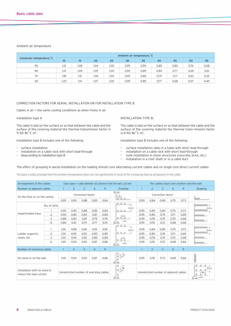
Arrangement of the cables Clearspace=cablediameter(d);distancefromthewall≥ 20 mm The cables touch one another and the wall
Number of adjacent cables 1 2 3 6 9 Drawing 1 2 3 6 9 Drawing
On the floor or on the ceilingCorrection factor
20 mm
dCorrection factor
0,95 0,90 0,88 0,85 0,84 0,90 0,84 0,80 0,75 0,73
Unperforated trays
No, of racks
20 mm
d
d
0,3 m 0,3 m1 0,95 0,90 0,88 0,85 0,84 0,95 0,84 0,80 0,75 0,73
2 0,90 0,85 0,83 0,81 0,80 0,95 0,80 0,75 0,71 0,69
3 0,88 0,83 0,81 0,79 0,78 0,95 0,78 0,74 0,70 0,68
6 0,86 0,81 0,79 0,77 0,76 0,95 0,76 0,72 0,68 0,66
Ladder supports,
cleats, etc.
1 1,00 0,98 0,96 0,93 0,92
20 mm
d
d
0,3 m 0,95 0,84 0,80 0,75 0,73 0,3 m
2 1,00 0,95 0,93 0,90 0,89 0,95 0,80 0,76 0,71 0,69
3 1,00 0,94 0,92 0,89 0,88 0,95 0,78 0,74 0,70 0,68
6 1,00 0,93 0,90 0,87 0,86 0,95 0,76 0,72 0,68 0,66
Number of overlying cables 1 2 3 6 9 1 2 3 6 9
On racks or on the wall 1,00 0,93 0,90 0,87 0,86
20 mm
dd
0,95 0,78 0,73 0,68 0,66
Installation with no need to
reduce the load currentUnrestricted number of overlying cables
20 mm
2dd
Unrestricted number of adjacent cables
20 mm
2d
d
0,3 m
The effect of grouping in aerial installation on the loading ofmulti core alternating current cables and on single core direct current cables
The data is valid, provided that the ambient temperature does not rise significantly in result of the increasing heat by dissipation in the cable.
Installation type A
The cable is laid on the surface or so that between the cable and the surface of the covering material the thermal transmission factor is 11–50 W/˚C m2.
Installation type B includes one of the following:
– surface installation– installation on a cable rack with short lead-through– disaccording to installation type B
INSTALLATION TYPE B: The cable is laid on the surface or so that between the cable and the surface of the covering material the thermal trans¬mission factor is K>50 W/˚C m2.
Installation type B includes one of the following:
– surface installation (also in a tube) with short lead-through– installation on a cable rack with short lead-through– sunk installation in stone structures (concrete, brick, etc.)– installation in a riser shaft or in a cable duct
Conductor temperature,˚CAmbient air temperature,˚C
10 15 20 25 30 35 40 45 50 55
90 1,12 1,08 1,04 1,00 0,95 0,90 0,85 0,80 0,74 0,68
80 1,14 1,09 1,05 1,00 0,95 0,89 0,84 0,77 0,69 0,61
70 1,18 1,12 1,06 1,00 0,95 0,86 0,79 0,71 0,62 0,52
65 1,20 1,14 1,07 1,00 0,95 0,85 0,77 0,68 0,57 0,45
Ambient air temperature
Cablesinair=thesamecoolingconditionsaswhenfreelyinair
CORRECTION FACTORS FOR AERIAL INSTALLATION OR FOR INSTALLATION TYPE B
Basic cable data
6 DRAKA KEILA CABLES PRODUCT CATALOQUE

Arrangement of the cables Flatformation,clearspace=cablediameter(d);distancefromthewall>20mm Cables touch one another and the wall
Number of adjacent systems 1 2 3 Drawing 1 2 3 Drawing
On the floor or on the ceilingCorrection factor
20 mmd d Correction factor
20 mm2d
2d
0,92 0,89 0,88 0,95 0,90 0,88
Unperforated trays
Number of racks
20 mmd d
0,3 m
20 mm2d
2d
0,3 m1 0,92 0,89 0,88 0,95 0,80 0,73
2 0,87 0,84 0,83 0,95 0,76 0,69
3 0,84 0,82 0,81 0,95 0,74 0,68
6 0,82 0,80 0,79 0,95 0,72 0,66
Ladder supports,
cleats, etc.
1 1,00 0,97 0,9620 mm
d d
0,3 m
1,00 0,98 0,9620 mm
2d2d
0,3 m2 0,97 0,94 0,93 1,00 0,95 0,93
3 0,96 0,93 0,92 1,00 0,94 0,92
6 0,94 0,91 0,90 1,00 0,93 0,90
Number of overlying systems 1 2 3 1 2 3
On racks or on the wall 0,94 0,91 0,89
20 mm
dd 0,89 0,88 0,84 2d
Installation with no need to the
load current
With a longer distance, there are more reduce losses in the metal sheath and in the armouring, while
cooling improves. Each case must be calculated separately.
20 mm
4d2d
0,3 m
The effect of grouping in aerial installation on the loading of single core alternating current cables
The data is valid, provided that the ambient temperature does not rise significantly in result of the increasing heat by dissipation in the cable.
Short circuit current capacity
Thermal stress
Taking into account the mechanical and electrical strength of the insulation, thermal stress by a short circuit is restricted by setting the maximum final conductor temperatures in a short circuit:
– XLPE-insulated cables . . . . . . . . . . . . . . . . . . . . . . . . . . . . . +250˚C– PVC-insulated 1 kV cables ≤ 300 mm2 . . . . . . . . . . . . . . . . +160˚C > 300 mm2 . . . . . . . . . . . . . . . . +140˚C
The given values for maximum permissible short circuit currents in cable data have been calculated assuming the initial conductor temperature to be the maximum operating temperature in continu-ous use.The listed short circuit currents for duration of one second indicate the thermal capacity of the conductor. The maximum permissible thermal short circuit current for duration of 0.2 to 5 seconds can be computed by the equation:
Ιt=Ι1s/√t
where
l1s=1sthermalshortcircuitcurrent[kA]t=durationoftheshortcircuit[s]
Dynamic stress
Short circuit currents cause a mechanical load on the cable as well as on the accessories.
The dynamic short circuit stress is much greater near the high volt-age network and near large power plants than farther out in the network. That is why the dynamic capacity of the accessories as well as the cable fittings must be checked. This is especially important with high power systems and with several parallel cables in aerial installation.
Most important in a short circuit is the peak value of current, which is 2.5 times the short circuit current. To minimize dynamic stress, the installation must be made using the right accessories and the right technique.
Basic cable data
7PRODUCT CATALOQUEDRAKA KEILA CABLES

ACSRAluminium conductor steel reinforced
Application Bare condutor for overhead power transmission. Highest permissible conductor temperature: – in continious operation . . . . . . . . . . . . . . . . . . . . . . . . . .80˚C – in a short circuit (duration up to 5 s) . . . . . . . . . . . . 200˚CConstruction A conductor consisting seven aluminium and galvanized steel wires, built up in concentric layers. The centre wire are steel and outer layer aluminium.Standards SFS 5701, IEC 61089, EN 50182
Basic data ACSR 34/6 ACSR 42/25 ACSR 54/9 ACSR 85/14 ACSR 89/52
SPARROW SAVO RAVEN PIGEON DOTTEREL
Product name according to IEC 34-A1/S1A-6/1 42-A1/S1A-12/7 54-A1/S1A-6/1 85-A1/S1A-6/1 89-A1/S1A-12/7
EAN-code 64 100+ 01 202 02-2 01 202 28-2 01 202 05-3 01 202 09-1 01 202 31-2
Construction data
Aluminium No of wires 6 12 6 6 6
Diameter of wire mm 2,68 2,12 3,37 4,25 3,08
Cross section mm2 33,8 42,4 53,5 85,1 89,4
Weight (5) kg/km 92,9 117 147 234,0 247,0
Steel No of wires 1 7 1 1 7
Diameter of wire mm 2,68 2,12 3,37 4,25 3,08
Cross section mm2 5,64 24,7 8,92 14,2 52,2
Weight (5) kg/km 43,9 193 69,4 110,0 408,0
Complete conductor No of wires 7 19 7 7 19
Diameter of conductor mm 8,04 10,6 10,1 12,8 15,4
Cross section mm2 39,5 67,1 62,4 99,3 142
Weight (5) kg/km 137 310 216 344,0 654,0
Delivery data
Standard delivery length m 2500 2500 2200 2000 2500
Standard delivery drum K11 K12 K11 K12 K16
Total weight (1) kg 390 860 560 770 1790
Mechanical data (2)
Minimum tensile strenght of the conductor kN 12,2 13,52 17,11 24,13 33,37
Initial modulus of elasticity of conductor N/mm2 64000 93000 64000 64000 93000
Final modulus of elasticity of conductor N/mm2 78000 102000 78000 78000 102000
Coefficient of linear expansion of conductor 1/K 19,2 x 10⁻⁶ 15,6 x 10⁻⁶ 19,2 x 10⁻⁶ 19,2 x 10⁻⁶ 15,6 x 10⁻⁶
Electrical data (2)
Maximum DC resistance of conductor (20 ˚C) (3) (5) Ω/km 0,848 0,682 0,536 0,337 0,323
Current ratings (6)
In air A 210 250 280 360 400
Short circuit currents (2)
Maximum permissible short circuit current for 1 sec. (4) kA 3,7 5,4 5,8 9,2 11,4
Power cables
8 DRAKA KEILA CABLES PRODUCT CATALOQUE
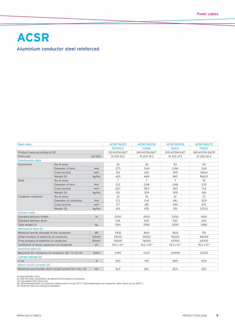
(1) Approximate value.(2) See the basic assumtions at general information of products.(3) Calculated with steel core.(4) Initial temperature of conductor before short circuit 40˚C, final temperature of conductor after short circuit 200˚C.(5) Nominal value according to standard.
ACSRAluminium conductor steel reinforced
Basic data ACSR 152/25 ACSR 242/39 ACSR 305/39 ACSR 565/72
OSTRICH HAWK DUCK FINCH
Product name according to IEC 152-A1/S1A-26/7 242-A1/S1A-26/7 305-A1/S1A-54/7 565-A1/S1A-54/19
EAN-code 64 100+ 01 202 15-2 01 202 18-3 01 202 21-3 01 202 24-4
Construction data
Alumiinium No of wires 26 26 54 54
Diameter of wire mm 2,73 3,44 2,68 3,65
Cross section mm2 152 242 305 565,0
Weight (5) kg/km 420 668 842 1562,0
Steel No of wires 7 7 7 19
Diameter of wire mm 2,12 2,68 2,68 2,19
Cross section mm2 24,7 39,5 39,5 71,6
Weight (5) kg/km 193 309 309 561
Complete conductor No of wires 33 33 61 73
Diameter of conductor mm 17,3 21,8 24,1 32,9
Cross section mm2 177 281 344 637
Weight (5) kg/km 613 976 1151 2123,0
Delivery data
Standard delivery length m 2500 2500 2200 1400
Standard delivery drum K18 K20 K22 K22
Total weight (1) kg 1760 2780 3290 3380
Mechanical data (2)
Minimum tensile strenght of the conductor kN 54,8 84,9 96,8 174
Initial modulus of elasticity of conductor N/mm2 61000 61000 50000 46000
Final modulus of elasticity of conductor N/mm2 76000 76000 67000 63000
Coefficient of linear expansion of conductor 1/K 19,2 x 10⁻⁶ 19,2 x 10⁻⁶ 19,3 x 10⁻⁶ 19,3 x 10⁻⁶
Electrical data (2)
Maximum DC resistance of conductor (20 ˚C) (3) (5) Ω/km 0,190 0,120 0,0949 0,0512
Current ratings (6)
In air A 550 745 845 1250
Short circuit currents (2)
Maximum permissible short circuit current for 1 sec. (4) kA 16,5 26,1 32,5 60,1
Power cables
9PRODUCT CATALOQUEDRAKA KEILA CABLES

Power cables
10 DRAKA KEILA CABLES PRODUCT CATALOGUE
HKCopper conductor
Application Grounding wire Highest permissible conductor temperature: – short circuit (duration up to 5s.) . . . . . . . . . . . . . . . . .200˚CConstruction Concentric stranded soft copper conductorStandard IEC 60228 Class 2Sertificate/approval CE, RoHS
(1) Approximate value(2) See the basic assumptions at general information of products.(3) Initial temperature of conductor before short circuit 40˚C, final temperature of conductor after short circuit 200˚C.
Product name HK HK HK HK HK HK
16/7x1.68 16/7x1.68 16/7x1.68 25/7x2.12 HK 16/7x1.68 HK 25/7x2.12
coil/25 m coil/50 m coil/100 m coil/100 m drum drum
EAN-code 64 100+ 01 050 05-0 01 050 06-7 01 050 07-4 01 050 25-8 01 550 07-9 01 050 08-1
Customs code 74.13.00.91 74.13.00.91 74.13.00.91 74.13.00.91 74.13.00.91 74.13.00.91
Constructional data
Number of wires 7 7 7 7 7 7
Diameter of wire mm 1,68 1,68 1,68 2,12 1,68 2,12
Diameter of conductor 5,04 5,04 5,04 6,36 5,04 6,36
Cross-section mm2 15,5 15,5 15,5 24,7 15,5 24,7
Weight of conductor (1) kg/km 140 140 140 222 140 222
Delivery data
Standard delivery length m 25 50 100 50 500 500
Standard delivery drum coil coil coil coil K6 K6
Weight (1) cable+drum kg 3,5 7 14 11 82 123
Electrical data (2)
Maximum DC resistance of conductor conductor 20˚C Ω/km 1,15 1,15 1,15 0,727 1,15 0,727
Short circuit currents (2)
Maximum permissible short circuit current for 1 second (3) kA 2,3 2,3 2,3 3,8 2,3 3,8
Product name HK HK HK HK HK
35/7x2.50 50/19x1.77 70/19x2.12 95/19x2.50 120/37x2.01
drum drum drum drum drum
EAN-code 64 100+ 01 050 09-8 01 050 10-4 01 050 11-1 01 050 12-8 01 050 13-5
Customs code 74.13.00.91 74.13.00.91 74.13.00.91 74.13.00.91 74.13.00.91
Constructional data
Number of wires 7 19 19 19 37
Diameter of wire mm 2,5 1,77 2,12 2,5 2,01
Diameter of conductor mm 7,5 8,85 10,6 12,5 14,1
Cross-section mm2 34,4 46,8 67,1 93,3 117
Weight of conductor (1) kg/km 309 422 606 843 1062
Delivery data
Standard delivery length m 1000 1000 1000 1000 1000
Standard delivery drum K7 K7 K9 K11 K11
Weight (1) cable+drum kg 329 642 640 898 1152
Electrical data (2)
Maximum DC resistance of conductor conductor 20˚C Ω/km 0,524 0,387 0,268 0,193 0,153
Short circuit currents (2)
Maximum permissible short circuit current for 1 second (3) kA 5,3 7,2 10,3 14,3 18
Maximum permissible short circuit current for 1 second (3) kA 10,3 14,3 18

Power cables
11PRODUCT CATALOGUEDRAKA KEILA CABLES
ASAluminium conductor steel reinforced AS
Application Bare condutor Highest permissible conductor temperature: – in continious operation . . . . . . . . . . . . . . . . . . . . . . . . . 80 ˚C – in a short circuit (duration up to 5 s) . . . . . . . . . . . . 200 ˚CConstruction Round, stranded aluminium steel reinforced conductor Standards GOST 889-80
Basic data AS 25 AS 35 AS 50 AS 70 AS 95
EAN-code 64 100+ 01 203 25 01 203 35 01 203 50 01 203 70 01 203 95
Construction data
Alumiinium No of wires 6 6 6 6 6
Diameter over wire mm 2,30 2,80 3,20 3,80 4,50
Cross section mm2 24,9 36,9 48,2 68,0 95,4
Weight (5) kg/km 68,3 101,3 132,3 188,0 261,0
Steel No of wires 1 1 1 1 1
Diameter over wire mm 2,30 2,80 3,20 3,80 4,50
Cross section mm2 4,15 6,15 8,04 11,3 15,9
Weight (5) kg/km 32,3 47,9 62,6 88,0 124,0
Conductor No of wires 7 7 7 7 7
Diameter over conductor mm 6,9 8,4 9,6 11,4 13,5
Cross section mm2 29,05 43,05 56,24 79,3 111,3
Weight (5) kg/km 100,7 149,2 194,9 276,0 385,0
Delivery data
Standard delivery length m 4000 4000 3500 2500 2500
Drum K9 K11 K11 K11 K14
Total weight (1) kg 430 645 740 745 1080
Mechanical data (2)
Minimum tensile strenght of the conductor kN 9,13 13,52 17,11 24,13 33,37
Initial modulus of elasticity of conductor N/mm2 64000 64000 64000 64000 64000
Final modulus of elasticity of conductor N/mm2 78000 78000 78000 78000 78000
Coefficient of linear expansion of conductor 1/K 19,2 x 10⁻⁶ 19,2 x 10⁻⁶ 19,2 x 10⁻⁶ 19,2 x 10⁻⁶ 19,2 x 10⁻⁶
Electrical data (2)
Maximum DC resistance of conductor (20 ˚C) (3) (5) Ω/km 1,1521 0,7774 0,5951 0,4218 0,3007
Current ratings (6)
In air A 142 175 210 265 330
Short circuit currents (2)
Maximum permissible short circuit current for 1 second (4) kA 2,7 4,0 5,3 7,5 10,5
(1) Approximate value.(2) See the basic assumtions at general information of products.(3) Calculated with steel.(4) Initial temperature of conductor before short circuit 40˚C, final temperature of conductor after short circuit 200˚C.(5) Standard based value.

Power cables
12 DRAKA KEILA CABLES PRODUCT CATALOGUE
ABare conductor A
Application Bare conductor Highest permissible conductor temperature: – in continious operation . . . . . . . . . . . . . . . . . . . . .80 ˚C – in a short circuit (duration up to 5 s) . . . . . . . .200 ˚CConstruction Round, stranded aluminium conductor Standards GOST 889-80
Basic data A 25 A 35 A 50 A 70 A 95
EAN-code 64 100+ 01 209 25 01 209 35 01 209 50 01 209 70 01 209 95
Construction data
No of wires 7 7 7 7 7
Diameter over wire mm 2,13 2,50 3,00 3,55 4,10
Cross section mm2 24,9 34,3 49,5 69,3 92,4
Weight (5) kg/km 68 94 135 189 252
Delivery data
Standard delivery length m 4000 4000 3500 2500 2500
Drum K9 K11 K11 K11 K12
Total weight (1) kg 300 425 520 520 720
Mechanical data (2)
Minimum tensile strenght of the conductor kN 4,50 5,91 8,19 11,28 14,78
Initial modulus of elasticity of conductor N/mm2 41000 41000 41000 41000 41000
Final modulus of elasticity of conductor N/mm2 60000 60000 60000 60000 60000
Coefficient of linear expansion of conductor 1/K 23,0 x 10⁻⁶ 23,0 x 10⁻⁶ 23,0 x 10⁻⁶ 23,0 x 10⁻⁶ 23,0 x 10⁻⁶
Electrical data (2)
Maximum DC resistance of conductor (20˚C) (3) (5) Ω/km 1,1498 0,8347 0,5784 0,4131 0,3114
Current ratings (6)
In air A 136 170 215 265 320
Short circuit currents (2)
Maximum permissible short circuit current for 1 second (4) kA 2,5 3,4 5,0 7,0 9,3
(1) Approximate value.(2) See the basic assumtions at general information of products.(3) Calculated with steel.(4) Initial temperature of conductor before short circuit 40˚C, final temperature of conductor after short circuit 200˚C.(5) Standard based value.

Power cables
13PRODUCT CATALOGUEDRAKA KEILA CABLES
AXMK & XMK 1-core1 kV power cable with XLPE insulated aluminium or copper conductor
Application For fixed installation indoors and outdoors Highest permissible conductor temperature: – in continious operation . . . . . . . . . . . . . . . . . . . . . . . . . .90˚C – in a short circuit (duration up to 5 s) . . . . . . . . . . . . .250˚C Lowest recommended handling temperature . . . . . . . .–15˚CConstruction Conductor AXMK – round, stranded and compacted aluminium conductor XMK – round, stranded and compacted copper conductor Insulation black XLPE compound Sheath black PVC compound Plastics are UV resistable and they don't need extra protection against sunlightStandards SFS 4879, HD 603-5D S1, IEC 60502-1, IEC 60332-1 Cat. B Certificate / approval EEI, FI, CERated voltage U0/U=0,6/1kV Um=1,2kVMarking Manufacturer, product name, date of manufacture, outer sheath material destignation, meter marking
Basic data AXMK AXMK XMK
1x300 1 kV 1x800 1 kV 1x300 1 kV
EAN-code 64 100+ 06 261 02-4 06 261 05-5 06 211 77-7
Construction data
External cable diameter (1) mm 29 44 29
Weight (1) aluminium kg/km 795 2160 -
copper kg/km - - 2620
cable kg/km 1150 2950 3050
Delivery data
Standard delivery length m 1000 500 1000
Drum K18 K20 K16
Total weight (1) cable + drum kg 1380 1810 3240
Mechanical data (2)
Minimum permissible bending radius during laying m 0,44 0,68 0,44
Minimum permissible bending radius at final installation (3) m 0,31 0,48 0,31
Maximum permissible pulling force with a pulling grip kN 4,5 8,5 4,5
Maximum permissible pulling force with a pulling eye kN 15,0 20,0 20,0
Electrical data (2)
Maximum DC resistance of conductor conductor 20˚C Ω/km 0,100 0,0367 0,0601
Current ratings (2)
In air
flat formation conductor 70˚C A 525 1000 665
trefoil formation conductor 70˚C A 460 830 580
flat formation conductor 90˚C A 690 1300 845
trefoil formation conductor 90˚C A 560 1050 735
Short circuit currents (2)
Maximum permissible short circuit current for 1 second (4) kA 28,3 75,6 42,8
(1) Approximate value. (2) See the basic assumtions at general information of products. (3) Final installation with careful single bending. (4) Initial temperature of conductor before short circuit 90˚C, final temperature of conductor after short circuit 250˚C.
Power cables
14 DRAKA KEILA CABLES PRODUCT CATALOGUE
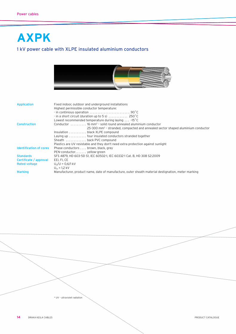
AXPK1 kV power cable with XLPE insulated aluminium conductors
Application Fixed indoor, outdoor and underground installations Highest permissible conductor temperature: - in continious operation . . . . . . . . . . . . . . . . . . . . . . . . . .90˚C - in a short circuit (duration up to 5 s) . . . . . . . . . . . . 250˚C Lowest recommended temperature during laying . . . –15˚CConstruction Conductor . . . . . . . . . . 16 mm2 – solid round annealed aluminium conductor 25–300 mm2 – stranded, compacted and annealed sector shaped aluminium conductor Insulation . . . . . . . . . . . black XLPE compound Laying up . . . . . . . . . . . four insulated conductors stranded together Sheath . . . . . . . . . . . . . back PVC compound Plastics are UV resistable and they don't need extra protection against sunlightIdentification of cores Phase conductors . . . . brown, black, grey PEN-conductor . . . . . . . yellow-greenStandards SFS 4879, HD 603-5D S1, IEC 60502-1, IEC 60332-1 Cat. B, HD 308 S2:2009Certificate / approval EEI, FI, CERated voltage U0/U=0,6/1kV Um=1,2kVMarking Manufacturer, product name, date of manufacture, outer sheath material destignation, meter marking
* UV – ultraviolet radiation

Power cables
15PRODUCT CATALOGUEDRAKA KEILA CABLES
Basic cable data 4G16 4G25 4G35 4G50 4G70 4G95
EAN-code 64 100+ 06 210 07-7 06 210 08-4 06 210 09-1 06 210 10-7 06 210 11-4 06 210 12-1
Construction data
External cable diameter (1) mm 20 21 23 27 30 34
Weight (1) aluminium kg/km 165 265 365 495 720 995
cable kg/km 380 500 670 830 1170 1500
Delivery data
Standard delivery length m 1000 1000 1000 1000 1000 1000
Drum K12 K14 K16 K16 K18 K20
Total weight (1) cable + drum kg 470 615 865 1025 1400 1840
Mechanical data (2)
Minimum permissible bending radius during laying m 0,24 0,26 0,28 0,33 0,36 0,41
Minimum permissible bending radius at final installation (3) m 0,17 0,19 0,20 0,23 0,26 0,29
Maximum permissible pulling force with a pulling grip kN 0,9 1,5 2,1 3,0 4,2 5,7
Maximum permissible pulling force with a pulling eye kN 3,2 5,0 7,0 10,0 14,0 19,0
Electrical data (2)
Maximum DC resistance of conductor 20˚C Ω/km 1,91 1,20 0,868 0,641 0,443 0,320
Maximum AC resistance of conductor 70˚C Ω/km 2,3 1,5 1,0 0,77 0,53 0,39
Current ratings (2)
In ground conductor 70˚C A 78 100 125 150 185 220
In air conductor 70˚C A 64 83 105 125 155 190
conductor 90˚C A 75 105 130 165 205 245
Short circuit currents (2)
Maximum permissible short circuit current for 1 second (4) kA 1,5 2,3 3,3 4,7 6,6 8,9
Basic cable data 4G120 4G150 4G185 4G240 4G300
EAN-code 64 100+ 06 21013-8 06 210 14-5 06 210 15-2 6 210 16-9
Construction data
External cable diameter (1) mm 38 42 47 53 58
Weight (1) aluminium kg/km 1260 1550 1950 2550 3190
cable kg/km 1900 2300 2800 3700 4600
Delivery data
Standard delivery length m 1000 500 500 500 500
Drum K22 K20 K20 K22 K24
Total weight (1) cable + drum kg 2310 1490 1740 2260 2750
Mechanical data (2)
Minimum permissible bending radius during laying m 0,46 0,51 0,57 0,64 0,70
Minimum permissible bending radius at final installation (3) m 0,33 0,36 0,40 0,45 0,49
Maximum permissible pulling force with a pulling grip kN 7,2 8,5 8,5 8,5 8,5
Maximum permissible pulling force with a pulling eye kN 20,0 20,0 20,0 20,0 20,0
Electrical data (2)
Maximum DC resistance of conductor 20˚C Ω/km 0,253 0,206 0,164 0,125 0,100
Maximum AC resistance of conductor 70˚C Ω/km 0,31 0,25 0,20 0,16 0,13
Current ratings (2)
In ground conductor 70˚C A 255 290 330 375 430
In air conductor 70˚C A 220 250 285 330 380
conductor 90˚C A 280 320 365 430 480
Short circuit currents (2)
Maximum permissible short circuit current for 1 second (4) kA 11,3 14,1 17,4 22,6 28,3
AXPK1 kV power cable with XLPE insulated aluminium conductors
(1) Approximate value.(2) See the basic assumtions at general information of products.(3) Final installation with careful single bending.(4) Initial temperature of conductor before short circuit 90˚C, final temperature of conductor after short circuit 250˚C.

Power cables
16 DRAKA KEILA CABLES PRODUCT CATALOGUE
EMC-Line 1kV (IFSI)Halogen-free installation cable with aluminium conductor
Application Power cable with rated voltage up to 1kV. Halogen-free cable for indoor and outdoor use, to secure areas from heavy smoke and corrosive gases in case of fire. Improved EMC screen according to EMC directive. National regulations for electrical installations must be followed.
Max conductor temperature . . 90O˚C Rated voltage U0/U . . . . . . . . . . 0,6/1 kV Cenelec designation . . . . . . . . . N1ZCZ1-AR (AS)Standards applied Construction . . . . . . . . . . . . . . . . CENELEC HD 604-5D Insulation . . . . . . . . . . . . . . . . . . IEC 60502-1 Flame retardancy . . . . . . . . . . . IEC 60332-3C Halogen-free . . . . . . . . . . . . . . . IEC 60754-1 and 2 Low smoke . . . . . . . . . . . . . . . . . IEC 61034Approvals NEMKO CE-marked, acc. to LVDConstruction Conductor . . . . . . . . . . . . . . . . . . stranded aluminium Insulation . . . . . . . . . . . . . . . . . . cross-linked halogen-free polymer Bedding/tape . . . . . . . . . . . . . . . halogen-free Concentric conductor . . . . . . . . copperfoil with overlap and concentric screen of copper wires (PE/PEN-conductor) Outer sheath . . . . . . . . . . . . . . . halogen-free Polymer Colour . . . . . . . . . . . . . . . . . . . . . black Marking . . . . . . . . . . . . . . . . . . . . printed on outer sheath, designation and dimension.
Metremarking and year of production. Mode of packing . . . . . . . . . . . . drum
Technical data
No. of cores and conductor area mm2 3x25/10 3 x 50/16 3 x 95/35 3 x 150/50 3 x 240/70
Conductor type *) AFR AFV AFV AFV AFV
Art. No. 478130 478170 478210 478553 478563
Outer diameter approx. mm 23 26 34 40 49
Approx. weight kg/km 550 850 1590 2290 3520
Normal delivery length m 500 500 500 500 400
*)ER=Solidround FR=Strandedround FV=Strandedsectorshaped
Technical data
No. of cores and conductor area mm2 4 x 25/10 4 x 50/16 4 x 95/35 4 x 150/50 4 x 240/70
Conductor type *) AFR AFV AFV AFV AFV
Art. No. 478135 478175 478215 478556 478566
Outer diameter approx. mm 25 29 36 45 55
Approx. weight kg/km 660 1050 1920 2820 4400
Normal delivery length m 500 500 500 500 400

Power cables
17PRODUCT CATALOGUEDRAKA KEILA CABLES
EMC-Line 1kV (IFSI)Halogen-free installation cable with copper conductor
Application Power cable with rated voltage up to 1kV. Halogen-free cable for indoor and outdoor use, to secure areas from heavy smoke and corrosive gases in case of fire. Improved EMC screen according to EMC directive. National regulations for electrical installations must be followed.
Max conductor temp. . . . . . 90O˚C Rated voltage U0/U . . . . . . . 0,6/1 kV Cenelec designation . . . . . . N1ZA5Z1-U, N1ZCZ1-U (R-S)Standards applied Construction . . . . . . . . . . . . . CENELEC HD 604-5D Insulation . . . . . . . . . . . . . . . IEC 60502-1 Flame retardancy . . . . . . . . IEC 60332-3C Halogen-free . . . . . . . . . . . . IEC 60754-1 and 2 Low Smoke . . . . . . . . . . . . . . IEC 61034 Approvals NEMKO, CE-marking, acc. to LVD Construction Conductor . . . . . . . . . . . . . . . solid or stranded copper Insulation . . . . . . . . . . . . . . . cross-linked Halogen-free Polymer Bedding/tape . . . . . . . . . . . . halogen-free Concentric conductor . . . . . 1,5–2,5 mm2 have aluminium tape with drain wire (PE/PEN-conductor) >4 mm2 have copperfoil with overlap and concentric screen of copper wires. Outer sheath . . . . . . . . . . . . halogen-free Polymer Colour . . . . . . . . . . . . . . . . . . black Marking . . . . . . . . . . . . . . . . . printed on outer sheath, designation and dimension. Metremarking and year of production. Mode of packing . . . . . . . . . drum
No. of cores and conductor area mm2 2 x 1,5/1,5 2 x 2,5/2,5 2 x 4/4 2 x 6/6 2 x 10/10 2 x 16/16 3 x 1,5/1,5 3 x 2,5/2,5 3 x 4/4
Conductor type *) ER ER ER ER FR FR ER ER ER
Art. No. 422005 422025 422045 422065 422085 422105 422010 422030 422050
Outer diameter approx. mm 11 12 13 14 18 20 11 12 13
Approx. weight kg/km 170 210 210 270 440 640 180 230 250
No. of cores and conductor area mm2 3 x 6/6 3 x 10/10 3 x 16/16 3 x 25/16 3 x 35/16 3 x 50/25 3 x 70/35 3 x 95/50 3 x 120/70
Conductor type *) ER FR FR FR FV FV FV FV FV
Art. No. 422070 422090 422110 422130 422150 422170 422190 422210 422230
Outer diameter approx. mm 14 18 21 24 24 26 30 33 38
Approx. weight kg/km 330 550 820 1110 1390 1800 2520 3450 4290
No. of cores and conductor area mm2 3 x 150/70 3 x 185/95 3 x 240/120 4 x 1,5/1,5 4 x 2,5/2,5 4 x 4/4 4 x 6/6 4 x 10/10 4 x 25/16
Conductor type *) FV FV FV ER ER ER ER FR FR
Art. No. 422250 422290 422015 422035 422055 422075 422095 422135
Outer diameter approx. mm 40 48 53 12 13 14 16 20 26
Approx. weight kg/km 5200 7200 8500 210 280 300 400 660 1370
No. of cores and conductor area mm2 4 x 35/16 4 x 50/25 4 x 70/35 4 x 95/50 4 x 120/70 4 x 150/70 4 x 185/95 4 x 240/120
Conductor type *) FV FV FV FV FV FV FV FV
Art. No. 422175 422195 422215 422235 422255 422275 422295
Outer diameter approx. mm 28 28 35 39 42 46 53 59
Approx. weight kg/km 1850 2270 3200 4380 5430 6590 8750 10900
*) ER – solid round, FR – stranded round, FV – stranded sector shaped

Power cables
18 DRAKA KEILA CABLES PRODUCT CATALOGUE
AMCMK 3 1/2-core1 kV power cable with PVC insulated aluminium conductors
Application Fixed indoor, outdoor and underground installations. Highest permissible conductor temperature: – in continious operation . . . . . . . . . . . . . . . . . . . . . . . . . . 70˚C – in a short circuit (duration up to 5 s) . . . . . . . . . . . . . 160˚C Lowest recommended temperature during laying . . . .–15˚CFire resistance class 25 – 300 mm2 . . . . . . . . IEC 60332-3 category B. 16 mm2 . . . . . . . . . . . . . . IEC 60332-1Construction Conductor . . . . . . . . . . . 16mm2 – solid round annealed aluminium conductor 25-300mm2 – stranded, compacted and annealed sector shaped aluminium conductor Insulation . . . . . . . . . . . PVC Laying up . . . . . . . . . . . three insulated phase conductors stranded together PEN-conductor . . . . . . . contcentrical copper wire layer and copper wire or copper tape binding Sheath . . . . . . . . . . . . . . black PVC compound Identification of cores Phase conductors brown, black, grey (HD 308 S2:2001) Standards SFS 4880 HD 603-3F S1 IEC 60502-1 IEC 60332-3 kat. BCertificate / approval FI, CERated voltage U0/U=0,6/1kV Um=1,2kVMarking Manufacturer, product name, date of manufacture, outer sheath material destignation, meter marking.
(1) Approximate value.(2) See the basic assumtions at general information of products.(3) Final installation with careful single bending.(4) Initial temperature of conductor before short circuit 70˚C, final temperature of conductor after short circuit 160˚C.(5) Initial temperature of PEN conductor before short circuit 65˚C, final temperature of PEN conductor after short circuit 160˚C.

Power cables
19PRODUCT CATALOGUEDRAKA KEILA CABLES
Basic cable data AMCMK AMCMK AMCMK AMCMK AMCMK AMCMK
3x16Al/10Cu 3x25Al/16Cu 3x35Al/16Cu 3x50Al/16Cu 3x70Al/21Cu 3x95Al/29Cu
AN 1 kV AN 1 kV AN 1 kV AN 1 kV AN 1 kV AN 1 kV
Construction data
External cable diameter (1) mm 22 23 24 28 31 35
Weight (1) aluminium kg/km 125 200 275 370 540 750
copper kg/km 95 145 145 145 190 260
cable kg/km 560 620 730 975 1300 1750
Delivery data
Standard delivery length m 1000 500 500 500 500 500
Drum 15G K11 K12 K12 K14 K14
Total weight (1) cable + drum kg 710 365 485 580 765 990
Mechanical data (2)
Minimum permissible bending radius during laying m 0,25 0,28 0,30 0,34 0,38 0,42
Minimum permissible bending radius at final installation (3) m 0,18 0,20 0,21 0,24 0,27 0,30
Maximum permissible pulling force with a pulling grip kN 0,7 1,1 1,6 2,2 3,1 4,3
Maximum permissible pulling force with a pulling eye kN 2,4 3,7 5,2 7,5 10,5 14,2
Electrical data (2)
Maximum DC resistance of conductor 20˚C Ω/km 1,91 1,20 0,868 0,641 0,443 0,320
Maximum AC resistance of conductor 70˚C Ω/km 2,3 1,4 1,0 0,77 0,53 0,39
Maximum DC resistance of PEN conductor 20˚C Ω/km 1,91 1,91 1,91 1,20 0,868 0,641
Inductance (1) mH/km 0,26 0,26 0,26 0,25 0,24 0,24
Operating capacitance (1) µF/km 0,40 0,45 0,55 0,60 0,65 0,75
Current ratings (2)
In air conductor 70˚C A 64 83 105 125 155 190
In ground conductor 70˚C A 78 100 125 150 185 220
Short circuit currents (2)
Maximum permissible short circuit phase conductor (4) kA 1,2 1,9 2,6 3,8 5,3 7,2
current for 1 second PEN conductor (5) kA 1,7 1,7 1,7 2,6 3,7 4,6
Basic cable data AMCMK AMCMK AMCMK AMCMK AMCMK
3x120Al/41Cu 3x150Al/41Cu 3x185Al/57Cu 3x240Al/72Cu 3x300Al/88Cu
AN 1 kV AN 1 kV AN 1 kV AN 1 kV AN 1 kV
Construction data
External cable diameter (1) mm 39 42 48 53 58
Weight (1) aluminium kg/km 945 1160 1460 1910 2390
copper kg/km 370 370 525 660 790
cable kg/km 2150 2550 3250 4100 5000
Delivery data
Standard delivery length m 500 500 500 500 500
Drum K16 K18 K20 K22 K24
Total weight (1) cable + drum kg 1270 1500 1950 2450 2950
Mechanical data (2)
Minimum permissible bending radius during laying m 0,47 0,51 0,58 0,64 0,70
Minimum permissible bending radius at final installation (3) m 0,33 0,36 0,41 0,45 0,49
Maximum permissible pulling force with a pulling grip kN 5,4 6,7 8,3 8,5 8,5
Maximum permissible pulling force with a pulling eye kN 18,0 20,0 20,0 20,0 20,0
Electrical data (2)
Maximum DC resistance of conductor 20˚C Ω/km 0,253 0,206 0,164 0,125 0,100
Maximum AC resistance of conductor 70˚C Ω/km 0,31 0,25 0,20 0,15 0,13
Maximum DC resistance of PEN conductor 20˚C Ω/km 0,443 0,443 0,320 0,253 0,206
Inductance (1) mH/km 0,23 0,23 0,23 0,23 0,23
Operating capacitance (1) µF/km 0,80 0,80 0,85 0,85 0,90
Current ratings (2)
In air conductor 70˚C A 220 250 285 330 380
In ground conductor 70˚C A 255 290 330 375 430
Short circuit currents (2)
Maximum permissible short circuit phase conductor (4) kA 9,1 11,4 14,0 18,2 22,8
current for 1 second PEN conductor (5) kA 6,7 6,7 8,8 11,4 13,9
AMCMK 3 1/2-core1 kV power cable with PVC insulated aluminium conductors

Power cables
20 DRAKA KEILA CABLES PRODUCT CATALOGUE
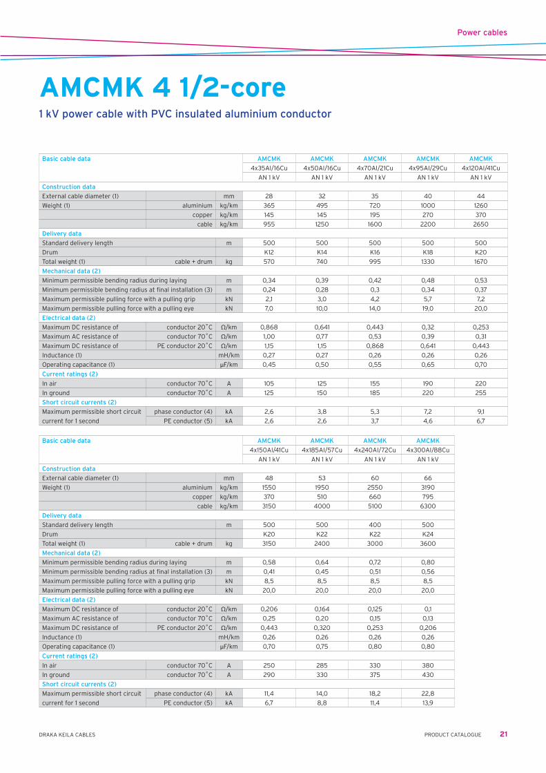
AMCMK 4 1/2-core1 kV power cable with PVC insulated aluminium conductors
Application Fixed indoor, outdoor and underground installations. Highest permissible conductor temperature: – in continious operation . . . . . . . . . . . . . . . . . . . . . . . . . . 70˚C – in a short circuit (duration up to 5 s) . . . . . . . . . . . . . 160˚C Lowest recommended temperature during laying . . . . -15˚CFire resistance class IEC 60332-3 cat BConstruction Conductor . . . . . . . . . . . stranded, compacted and annealed sector shaped aluminium conductor Insulation . . . . . . . . . . . PVC Laying up . . . . . . . . . . . three insulated phase conductors and neutral conductor stranded together PE-conductor . . . . . . . . concentric copper wire layer and copper wire or copper tape binding Sheath . . . . . . . . . . . . . . black PVC compoundIdentification of cores Phase conductors brown, black, grey and neutral conductor blue (HD 308 S2:2001) Standards SFS 4880, HD 603-3F S1, IEC 60502-1 Certificate / approval EEI, FI, CERated voltage U0/U=0,6/1kV Um=1,2kVMarking Manufacturer, product name, date of manufacture, outer sheath material destignation, meter marking.
(1) Approximate value.(2) See the basic assumtions at general information of products.(3) Final installation with careful single bending.(4) Initial temperature of conductor before short circuit 70˚C, final temperature of conductor after short circuit 160˚C.(5) Initial temperature of PE conductor before short circuit 65˚C, final temperature of PE conductor after short circuit 160˚C.
Power cables
21PRODUCT CATALOGUEDRAKA KEILA CABLES
Basic cable data AMCMK AMCMK AMCMK AMCMK AMCMK
4x35Al/16Cu 4x50Al/16Cu 4x70Al/21Cu 4x95Al/29Cu 4x120Al/41Cu
AN 1 kV AN 1 kV AN 1 kV AN 1 kV AN 1 kV
Construction data
External cable diameter (1) mm 28 32 35 40 44
Weight (1) aluminium kg/km 365 495 720 1000 1260
copper kg/km 145 145 195 270 370
cable kg/km 955 1250 1600 2200 2650
Delivery data
Standard delivery length m 500 500 500 500 500
Drum K12 K14 K16 K18 K20
Total weight (1) cable + drum kg 570 740 995 1330 1670
Mechanical data (2)
Minimum permissible bending radius during laying m 0,34 0,39 0,42 0,48 0,53
Minimum permissible bending radius at final installation (3) m 0,24 0,28 0,3 0,34 0,37
Maximum permissible pulling force with a pulling grip kN 2,1 3,0 4,2 5,7 7,2
Maximum permissible pulling force with a pulling eye kN 7,0 10,0 14,0 19,0 20,0
Electrical data (2)
Maximum DC resistance of conductor 20˚C Ω/km 0,868 0,641 0,443 0,32 0,253
Maximum AC resistance of conductor 70˚C Ω/km 1,00 0,77 0,53 0,39 0,31
Maximum DC resistance of PE conductor 20˚C Ω/km 1,15 1,15 0,868 0,641 0,443
Inductance (1) mH/km 0,27 0,27 0,26 0,26 0,26
Operating capacitance (1) µF/km 0,45 0,50 0,55 0,65 0,70
Current ratings (2)
In air conductor 70˚C A 105 125 155 190 220
In ground conductor 70˚C A 125 150 185 220 255
Short circuit currents (2)
Maximum permissible short circuit phase conductor (4) kA 2,6 3,8 5,3 7,2 9,1
current for 1 second PE conductor (5) kA 2,6 2,6 3,7 4,6 6,7
Basic cable data AMCMK AMCMK AMCMK AMCMK
4x150Al/41Cu 4x185Al/57Cu 4x240Al/72Cu 4x300Al/88Cu
AN 1 kV AN 1 kV AN 1 kV AN 1 kV
Construction data
External cable diameter (1) mm 48 53 60 66
Weight (1) aluminium kg/km 1550 1950 2550 3190
copper kg/km 370 510 660 795
cable kg/km 3150 4000 5100 6300
Delivery data
Standard delivery length m 500 500 400 500
Drum K20 K22 K22 K24
Total weight (1) cable + drum kg 3150 2400 3000 3600
Mechanical data (2)
Minimum permissible bending radius during laying m 0,58 0,64 0,72 0,80
Minimum permissible bending radius at final installation (3) m 0,41 0,45 0,51 0,56
Maximum permissible pulling force with a pulling grip kN 8,5 8,5 8,5 8,5
Maximum permissible pulling force with a pulling eye kN 20,0 20,0 20,0 20,0
Electrical data (2)
Maximum DC resistance of conductor 20˚C Ω/km 0,206 0,164 0,125 0,1
Maximum AC resistance of conductor 70˚C Ω/km 0,25 0,20 0,15 0,13
Maximum DC resistance of PE conductor 20˚C Ω/km 0,443 0,320 0,253 0,206
Inductance (1) mH/km 0,26 0,26 0,26 0,26
Operating capacitance (1) µF/km 0,70 0,75 0,80 0,80
Current ratings (2)
In air conductor 70˚C A 250 285 330 380
In ground conductor 70˚C A 290 330 375 430
Short circuit currents (2)
Maximum permissible short circuit phase conductor (4) kA 11,4 14,0 18,2 22,8
current for 1 second PE conductor (5) kA 6,7 8,8 11,4 13,9
AMCMK 4 1/2-core1 kV power cable with PVC insulated aluminium conductor
Power cables
22 DRAKA KEILA CABLES PRODUCT CATALOGUE
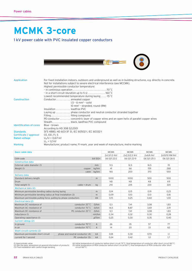
MCMK 3-core1 kV power cable with PVC insulated copper conductors
Application For fixed installation indoors, outdoors and underground as well as in building structures, e.g. directly in concrete. Not for installations subject to severe electrical interference (see MCCMK).
Highest permissible conductor temperature: – in continious operation . . . . . . . . . . . . . . . . . . . . . . . . . . 70˚C – in a short circuit (duration up to 5 s) . . . . . . . . . . . . . 160˚C Lowest recommended temperature during laying . . . . -15˚CConstruction Conductor . . . . . . . . . . . annealed copper 1,5 – 6 mm2 – solid 10 mm2 – stranded, round (RM) Insulation . . . . . . . . . . . leadfree PVC Laying up . . . . . . . . . . . phase conductor and neutral conductor stranded together Filling . . . . . . . . . . . . . . . filling compound PE-conductor . . . . . . . . concentric layer of copper wires and an open helix of parallel copper wires Sheath . . . . . . . . . . . . . . black, laedfree PVC compoundIdentification of cores Blue – brown According to HD 308 S2:2001Standards SFS 4880, HD 603-3F S1, IEC 60502-1, IEC 60332-1Certificate / approval CE, EEI, FI, SRated voltage U0/U=0,6/1kV Um=1,2kVMarking Manufacturer, product name, FI-mark, year and week of manufacture, metre marking
Basic cable data MCMK MCMK MCMK MCMK
2x1,5/1,5 1kV 2x2,5/2,5 1kV 2x6/6 1kV 2x10/10 RM 1kV
EAN-code 64 100+ 06 021 22-2 06 021 23-9 06 021 25-3 06 021 26-0
Construction data
External cable diameter (1) mm 11,5 12,5 16,5 19
Weight (1) copper kg/km 41 66 159 268
cable kg/km 165 200 370 550
Delivery data
Standard delivery length m 1000 1000 500 500
Drum K8 K8 K8 K9
Total weight (1) cable + drum kg 210 225 220 320
Mechanical data (2)
Minimum permissible bending radius during laying m 0,14 0,15 0,19 0,23
Minimum permissible bending radius at final installation (3) m 0,09 0,10 0,13 0,16
Maximum permissible pulling force, pulling by phase conductors kN 0,15 0,25 0,60 1,00
Electrical data (2)
Maximum DC resistance of conductor 20˚C Ω/km 12,1 7,41 3,08 1,83
Maximum AC resistance of conductor 70˚C Ω/km 14,5 8,87 3,69 2,19
Maximum DC resistance of PE conductor 20˚C Ω/km 12,1 7,41 3,08 1,83
Inductance (1) mH/km 0,34 0,32 0,30 0,28
Operating capacitance (1) µF/km 0,25 0,30 0,35 0,40
Current ratings (2)
In ground conductor 70˚C A 26 35 57 77
In air conductor 70˚C A 14 20 33 62
Short circuit currents (2)
Maximum permissible short circuit phase and neutral conductor (4) kA 0,18 0,30 0,70 1,1
current for 1 second PE conductor (5) kA 0,24 0,42 1,0 1,7
(1) Approximate value.(2) See the basic assumtions at general information of products.(3) Final installation with careful single bending.
(4) Initial temperature of conductor before short circuit 70˚C, final temperature of conductor after short circuit 160˚C.(5) Initial temperature of PEN conductor before short circuit 60˚C, final temperature of PEN conductor after short circuit 160˚C.
Power cables
23PRODUCT CATALOGUEDRAKA KEILA CABLES
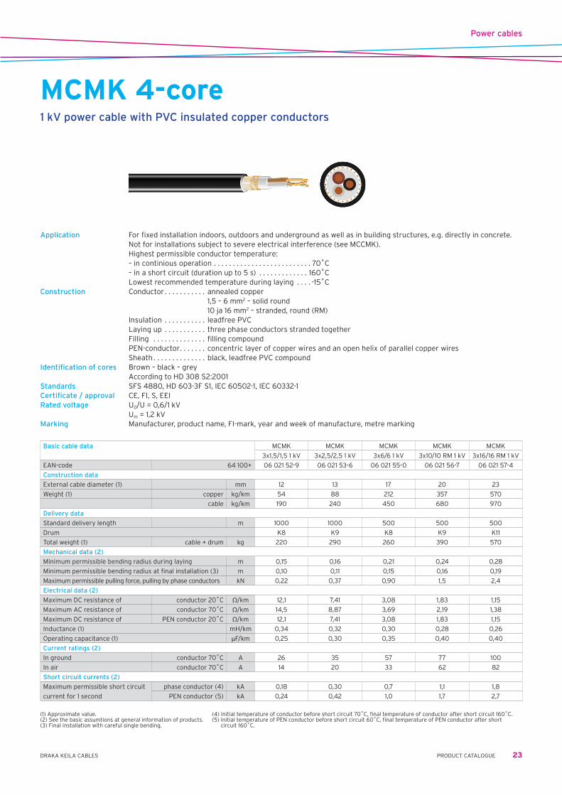
MCMK 4-core1 kV power cable with PVC insulated copper conductors
Application For fixed installation indoors, outdoors and underground as well as in building structures, e.g. directly in concrete. Not for installations subject to severe electrical interference (see MCCMK).
Highest permissible conductor temperature: – in continious operation . . . . . . . . . . . . . . . . . . . . . . . . . . 70˚C – in a short circuit (duration up to 5 s) . . . . . . . . . . . . . 160˚C Lowest recommended temperature during laying . . . . -15˚CConstruction Conductor . . . . . . . . . . . annealed copper 1,5 – 6 mm2 – solid round 10 ja 16 mm2 – stranded, round (RM) Insulation . . . . . . . . . . . leadfree PVC Laying up . . . . . . . . . . . three phase conductors stranded together Filling . . . . . . . . . . . . . . filling compound PEN-conductor . . . . . . . concentric layer of copper wires and an open helix of parallel copper wires Sheath . . . . . . . . . . . . . . black, leadfree PVC compoundIdentification of cores Brown – black – grey According to HD 308 S2:2001Standards SFS 4880, HD 603-3F S1, IEC 60502-1, IEC 60332-1Certificate / approval CE, FI, S, EEIRated voltage U0/U=0,6/1kV Um=1,2kVMarking Manufacturer, product name, FI-mark, year and week of manufacture, metre marking
Basic cable data MCMK MCMK MCMK MCMK MCMK
3x1,5/1,5 1 kV 3x2,5/2,5 1 kV 3x6/6 1 kV 3x10/10 RM 1 kV 3x16/16 RM 1 kV
EAN-code 64 100+ 06 021 52-9 06 021 53-6 06 021 55-0 06 021 56-7 06 021 57-4
Construction data
External cable diameter (1) mm 12 13 17 20 23
Weight (1) copper kg/km 54 88 212 357 570
cable kg/km 190 240 450 680 970
Delivery data
Standard delivery length m 1000 1000 500 500 500
Drum K8 K9 K8 K9 K11
Total weight (1) cable + drum kg 220 290 260 390 570
Mechanical data (2)
Minimum permissible bending radius during laying m 0,15 0,16 0,21 0,24 0,28
Minimum permissible bending radius at final installation (3) m 0,10 0,11 0,15 0,16 0,19
Maximum permissible pulling force, pulling by phase conductors kN 0,22 0,37 0,90 1,5 2,4
Electrical data (2)
Maximum DC resistance of conductor 20˚C Ω/km 12,1 7,41 3,08 1,83 1,15
Maximum AC resistance of conductor 70˚C Ω/km 14,5 8,87 3,69 2,19 1,38
Maximum DC resistance of PEN conductor 20˚C Ω/km 12,1 7,41 3,08 1,83 1,15
Inductance (1) mH/km 0,34 0,32 0,30 0,28 0,26
Operating capacitance (1) µF/km 0,25 0,30 0,35 0,40 0,40
Current ratings (2)
In ground conductor 70˚C A 26 35 57 77 100
In air conductor 70˚C A 14 20 33 62 82
Short circuit currents (2)
Maximum permissible short circuit phase conductor (4) kA 0,18 0,30 0,7 1,1 1,8
current for 1 second PEN conductor (5) kA 0,24 0,42 1,0 1,7 2,7
(1) Approximate value.(2) See the basic assumtions at general information of products.(3) Final installation with careful single bending.
(4) Initial temperature of conductor before short circuit 70˚C, final temperature of conductor after short circuit 160˚C.(5) Initial temperature of PEN conductor before short circuit 60˚C, final temperature of PEN conductor after short circuit 160˚C.

Power cables
24 DRAKA KEILA CABLES PRODUCT CATALOGUE
MCMK 5-core1 kV power cable with PVC insulated copper conductors
Application For fixed installation indoors, outdoors and underground as well as in building structures, e.g. directly in concrete. Not for installations subject to severe electrical interference (see MCCMK).
Highest permissible conductor temperature: – in continious operation . . . . . . . . . . . . . . . . . . . . . . . . . . 70˚C – in a short circuit (duration up to 5 s) . . . . . . . . . . . . . 160˚C Lowest recommended temperature during laying . . . . -15˚CConstruction Conductor . . . . . . . . . . . annealed copper 1,5 – 6 mm2 – solid 10 ja 16 mm2 – stranded, round (RM) Insulation . . . . . . . . . . . leadfree PVC Laying up . . . . . . . . . . . three phase conductors and neutral conductor stranded together Filling . . . . . . . . . . . . . . filling compound PEN-conductor . . . . . . . concentric layer of copper wires and an open helix of parallel copper wires Sheath . . . . . . . . . . . . . . black, laedfree PVC compoundIdentification of cores Blue – brown – black – grey According HD 308 S2:2001 Standards SFS 4880, HD 603-3F S1, IEC 60502-1, IEC 60332-1 Certificate / approval EEI, CE, FI, SRated voltage U0/U=0,6/1kV Um=1,2kVMarking Manufacturer, product name, FI-mark, year and week of manufacture, metre marking
(1) Approximate value.(2) See the basic assumtions at general information of products.(3) Final installation with careful single bending.(4) Initial temperature of conductor before short circuit 70˚C, final temperature of conductor after short circuit 160˚C.(5) Initial temperature of PE conductor before short circuit 60˚C, final temperature of PE conductor after short circuit 160˚C.

Power cables
25PRODUCT CATALOGUEDRAKA KEILA CABLES
Basic cable data MCMK MCMK MCMK MCMK
4x1,5/1,5 1kV 4x1,5/1,5 1kV 4x2,5/2,5 1kV 4x2,5/2,5 1kV
drum reel drum reel
EAN-code 64 100+ 06 021 72-7 06 021 92-5 06 021 43-7 06 021 93-2
Construction data
External cable diameter (1) mm 13 13 14 14
Weight (1) copper kg/km 68 68 110 110
cable kg/km 210 210 270 270
Delivery data
Standard delivery length m 1000 100 1000 100
Drum K8 reel K9 reel
Total weight (1) cable + drum kg 235 21 320 27
Mechanical data (2)
Minimum permissible bending radius during laying m 0,16 0,16 0,17 0,17
Minimum permissible bending radius at final installation (3) m 0,11 0,11 0,12 0,12
Maximum permissible pulling force, pulling by phase conductors kN 0,3 0,3 0,5 0,5
Electrical data (2)
Maximum DC resistance of conductor 20˚C Ω/km 12,1 12,1 7,41 7,41
Maximum AC resistance of conductor 70˚C Ω/km 14,5 14,5 8,87 8,87
Maximum DC resistance of PE conductor 20˚C Ω/km 12,1 12,1 7,41 7,41
Inductance (1) mH/km 0,34 0,34 0,32 0,32
Operating capacitance (1) µF/km 0,25 0,25 0,30 0,30
Current ratings (2)
In ground conductor 70˚C A 26 26 35 35
In air conductor 70˚C A 14 14 20 20
Short circuit currents (2)
Maximum permissible short circuit phase and neutral conductor (4) kA 0,18 0,18 0,30 0,30
current for 1 second PE conductor (5) kA 0,24 0,24 0,42 0,42
Basic cable data MCMK MCMK MCMK
4x6/6 1kV 4x10/10 RM 1kV 4x16/16 RM 1kV
drum drum drum
EAN-code 64 100+ 06 021 45-1 06 021 46-8 06 021 47-5
Construction data
External cable diameter (1) mm 18,5 22 25
Weight (1) copper kg/km 265 447 712
cable kg/km 520 790 1150
Delivery data
Standard delivery length m 500 500 500
Drum K8 K11 K11
Total weight (1) cable + drum kg 285 480 630
Mechanical data (2)
Minimum permissible bending radius during laying m 0,22 0,25 0,29
Minimum permissible bending radius at final installation (3) m 0,15 0,17 0,20
Maximum permissible pulling force, pulling by phase conductors kN 1,2 2,0 3,2
Electrical data (2)
Maximum DC resistance of conductor 20˚C Ω/km 3,08 1,83 1,15
Maximum AC resistance of conductor 70˚C Ω/km 3,69 2,19 1,38
Maximum DC resistance of PE conductor 20˚C Ω/km 3,08 1,83 1,15
Inductance (1) mH/km 0,30 0,28 0,26
Operating capacitance (1) µF/km 0,35 0,40 0,40
Current ratings (2)
In ground conductor 70˚C A 57 77 100
In air conductor 70˚C A 33 62 82
Short circuit currents (2)
Maximum permissible short circuit phase and neutral conductor (4) kA 0,70 1,1 1,8
current for 1 second PE conductor (5) kA 1,0 1,7 2,7
MCMK 5-core1 kV power cable with PVC insulated copper conductors

Power cables
26 DRAKA KEILA CABLES PRODUCT CATALOGUE
MCCMK 4-core1 kV EMC power cable with PVC-insulated copper conductor
Application Fixed indoor, outdoor and underground installation where EMC-properties are required. Highest permissible conductor temperature: – in continious operation . . . . . . . . . . . . . . . . . . . . . . . . . . 70˚C – in a short circuit (duration up to 5 s) . . . . . . . . . . . . . 160˚C Lowest recommended temperature during laying . . . . -15˚CConstruction Conductor . . . . . . . . . . . annealed copper 2,5 and 6 mm2 – solid round 10 ja 16 mm2 – stranded round (RM) Insulation . . . . . . . . . . . leadfree PVC Laying up . . . . . . . . . . . three phase conductors stranded together Filling . . . . . . . . . . . . . . filling compound PEN-conductor . . . . . . . copper foil and concentric layer of copper wires Sheath . . . . . . . . . . . . . . black, leadfree PVC compoundIdentification of cores Colour marking: brown – black – grey According to HD 308 S2:2001 Standards SFS 4880, HD 603-3F S1, IEC 60502-1, IEC 60322-1 Certificate / approval EEI, FI, CERated voltage U0/U=0,6/1kV Um=1,2kVMarking Manufacturer, product name, FI-mark, year and week of manufacture, metre marking
(1) Approximate value.(2) See the basic assumtions at general information of products.(3) Final installation with careful single bending.(4) Initial temperature of conductor before short circuit 70˚C, final temperature of conductor after short circuit 160˚C.(5) Initial temperature of PEN conductor before short circuit 60˚C, final temperature of PEN conductor after short circuit 160˚C.
Basic cable data MCCMK MCCMK MCCMK MCCMK
3x2,5/2,5 1 kV 3x6/6 1 kV 3x10/10 RM 1 kV 3x16/16 RM 1 kV
EAN-code 64 100+ 06 020 53-9 06 020 55-3 06 020 56-0 06 020 57-7
Construction data
External cable diameter (1) mm 14 18 21 24
Weight (1) copper kg/km 88 212 357 570
cable kg/km 260 470 700 1050
Delivery data
Standard delivery length m 1000 1000 1000 1000
Drum K9 K11 K12 15G
Total weight (1) cable + drum kg 320 560 820 1250
Mechanical data (2)
Minimum permissible bending radius during laying m 0,16 0,22 0,25 0,30
Minimum permissible bending radius at final installation (3) m 0,11 0,15 0,17 0,20
Maximum permissible pulling force with a pulling grip kN 0,37 0,90 1,5 2,4
Electrical data (2)
Maximum DC resistance of conductor 20˚C Ω/km 7,41 3,08 1,83 1,15
Maximum AC resistance of conductor 70˚C Ω/km 8,87 3,69 2,19 1,38
Maximum DC resistance of PEN conductor 20˚C Ω/km 7,41 3,08 1,83 1,15
Inductance (1) mH/km 0,32 0,30 0,26 0,26
Operating capacitance (1) µF/km 0,30 0,35 0,40 0,40
Current ratings (2)
In ground conductor 70˚C A 35 57 77 100
In air conductor 70˚C A 20 33 62 82
Short circuit currents (2)
Maximum permissible short circuit phase conductor (4) kA 0,18 0,30 0,7 1,1
current for 1 second PEN conductor (5) kA 0,24 0,42 1,0 1,7
Power cables
27PRODUCT CATALOGUEDRAKA KEILA CABLES
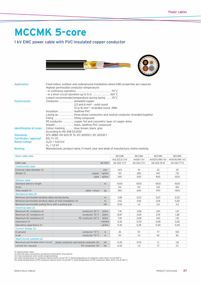
MCCMK 5-core1 kV EMC power cable with PVC-insulated copper conductor
Application Fixed indoor, outdoor and underground installation where EMC-properties are required. Highest permissible conductor temperature: – in continious operation . . . . . . . . . . . . . . . . . . . . . . . . . . 70˚C – in a short circuit (duration up to 5 s) . . . . . . . . . . . . . 160˚C Lowest recommended temperature during laying . . . . -15˚CConstruction Conductor . . . . . . . . . . . annealed copper 2,5 and 6 mm2 – solid round 10 ja 16 mm2 – stranded round (RM) Insulation . . . . . . . . . . . leadfree PVC Laying up . . . . . . . . . . . three phase conductors and neutral conductor stranded together Filling . . . . . . . . . . . . . . filling compound PE-conductor . . . . . . . . copper foil and concentric layer of copper wires Sheath . . . . . . . . . . . . . . black, laedfree PVC compoundIdentification of cores Colour marking . . . . . . blue, brown, black, grey According to HD 308 S2:2001 Standards SFS 4880, HD 603-3F S1, IEC 60502-1, IEC 60332-1 Certificate / approval EEI, FI, CERated voltage U0/U=0,6/1kV Um=1,2kVMarking Manufacturer, product name, FI-mark, year and week of manufacture, metre marking
(1) Approximate value.(2) See the basic assumtions at general information of products.(3) Final installation with careful single bending.(4) Initial temperature of conductor before short circuit 70˚C, final temperature of conductor after short circuit 160˚C.(5) Initial temperature of PE conductor before short circuit 60˚C, final temperature of PE conductor after short circuit 160˚C.
Basic cable data MCCMK MCCMK MCCMK MCCMK
4x2,5/2,5 1 kV 4x6/6 1 kV 4x10/10 RM 1 kV 4x16/16 RM 1 kV
EAN-code 64 100+ 06 020 73-7 06 020 75-1 06 020 76-8 06 020 77-5
Construction data
External cable diameter (1) mm 14,5 19 22 25
Weight (1) copper kg/km 110 265 447 712
cable kg/km 290 540 830 1200
Delivery data
Standard delivery length m 1000 1000 1000 1000
Drum K9 K11 13G 15G
Total weight (1) cable + drum kg 350 640 970 1400
Mechanical data (2)
Minimum permissible bending radius during laying m 0,18 0,23 0,27 0,30
Minimum permissible bending radius at final installation (3) m 0,12 0,16 0,18 0,20
Maximum permissible pulling force with a pulling grip kN 0,50 1,2 2,0 3,2
Electrical data (2)
Maximum DC resistance of conductor 20˚C Ω/km 7,41 3,08 1,83 1,15
Maximum AC resistance of conductor 70˚C Ω/km 8,87 3,69 2,19 1,38
Maximum DC resistance of PE conductor 20˚C Ω/km 7,41 3,08 1,83 1,15
Inductance (1) mH/km 0,32 0,30 0,28 0,26
Operating capacitance (1) µF/km 0,30 0,35 0,40 0,40
Current ratings (2)
In ground conductor 70˚C A 35 57 77 100
In air conductor 70˚C A 20 33 62 82
Short circuit currents (2)
Maximum permissible short circuit phase conductor and neutral conductor (4) kA 0,30 0,70 1,1 1,8
current for 1 second PE conductor (5) kA 0,42 1,0 1,7 2,7
Power cables
28 DRAKA KEILA CABLES PRODUCT CATALOGUE
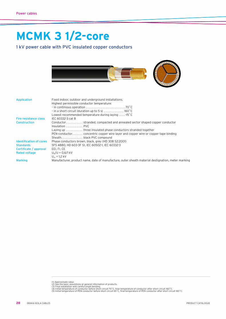
MCMK 3 1/2-core1 kV power cable with PVC insulated copper conductors
Application Fixed indoor, outdoor and underground installations. Highest permissible conductor temperature: – in continious operation . . . . . . . . . . . . . . . . . . . . . . . . . . 70˚C – in a short circuit (duration up to 5 s) . . . . . . . . . . . . . 160˚C Lowest recommended temperature during laying . . . . -15˚CFire resistance class IEC 60332-3 cat BConstruction Conductor . . . . . . . . . . . stranded, compacted and annealed sector shaped copper conductor Insulation . . . . . . . . . . . PVC Laying up . . . . . . . . . . . three insulated phase conductors stranded together PEN-conductor . . . . . . . concentric copper wire layer and copper wire or copper tape binding Sheath . . . . . . . . . . . . . . black PVC compoundIdentification of cores Phase conductors brown, black, grey (HD 308 S2:2001) Standards SFS 4880, HD 603-3F S1, IEC 60502-1, IEC 60332-3 Certificate / approval EEI, FI, CERated voltage U0/U=0,6/1kV Um=1,2kVMarking Manufacturer, product name, date of manufacture, outer sheath material destignation, meter marking
(1) Approximate value.(2) See the basic assumtions at general information of products.(3) Final installation with careful single bending.(4) Initial temperature of conductor before short circuit 70˚C, final temperature of conductor after short circuit 160˚C.(5) Initial temperature of PEN conductor before short circuit 65˚C, final temperature of PEN conductor after short circuit 160˚C.

Power cables
29PRODUCT CATALOGUEDRAKA KEILA CABLES
Basic cable data MCMK MCMK MCMK MCMK MCMK
3x25/16 AN 1 kV 3x35/16 AN 1 kV 3x50/25 AN 1 kV 3x70/35 AN 1 kV 3x95/50 AN 1 kV
EAN-code 64 100+ 06 021 58-1 06 021 59-8 06 021 60-4 06 021 61-1 06 021 62-8
Construction data
External cable diameter (1) mm 23 25 28 31 37
Weight (1) copper kg/km 800 1050 1460 2080 2880
cable kg/km 1150 1450 2000 2700 3700
Delivery data
Standard delivery length m 500 500 500 500 500
Drum K12 K12 K12 K14 K16
Total weight (1) cable + drum kg 630 815 1090 1470 2050
Mechanical data (2)
Minimum permissible bending radius during laying m 0,28 0,30 0,34 0,38 0,45
Minimum permissible bending radius at final installation (3) m 0,20 0,21 0,24 0,26 0,31
Maximum permissible pulling force with a pulling grip kN 1,1 1,5 2,2 3,1 4,2
Maximum permissible pulling force with a pulling eye kN 7,5 10,5 15,0 20,0 20,0
Electrical data (2)
Maximum DC resistance of conductor 20˚C Ω/km 0,727 0,524 0,387 0,268 0,193
Maximum AC resistance of conductor 70˚C Ω/km 0,87 0,63 0,47 0,32 0,23
Maximum DC resistance of PEN conductor 20˚C Ω/km 1,15 1,15 0,727 0,524 0,387
Inductance (1) mH/km 0,26 0,26 0,25 0,24 0,24
Operating capacitance (1) µF/km 0,45 0,55 0,60 0,65 0,75
Current ratings (2)
In air conductor 70˚C A 107 135 160 200 245
In ground conductor 70˚C A 130 160 190 240 285
Short circuit currents (2)
Maximum permissible short phase conductor (4) kA 2,8 4,0 5,7 8,0 10,9
circuit current for 1 second PEN conductor (5) kA 2,7 2,7 4,4 5,7 7,2
Basic cable data MCMK MCMK MCMK MCMK MCMK
3x120/70 AN 1 kV 3x150/70 AN 1 kV 3x185/95 AN 1 kV 3x240/120 AN 1 kV 3x300/150 AN 1 kV
EAN-code 64 100+ 06 021 63-5 06 021 64-2 06 021 65-9 06 021 66-6 06 021 75-8
Construction data
External cable diameter (1) mm 39 43 48 59 59
Weight (1) copper kg/km 3710 4430 5630 7350 9240
cable kg/km 4650 5550 7000 9100 11500
Delivery data
Standard delivery length m 500 500 500 500 500
Drum K18 K18 K20 K22 K24
Total weight (1) cable + drum kg 2560 3000 3850 4950 6200
Mechanical data (2)
Minimum permissible bending radius during laying m 0,47 0,52 0,58 0,64 0,71
Minimum permissible bending radius at final installation (3) m 0,33 0,37 0,41 0,45 0,50
Maximum permissible pulling force with a pulling grip kN 5,4 6,7 8,3 8,5 8,5
Maximum permissible pulling force with a pulling eye kN 20,0 20,0 20,0 20,0 20,0
Electrical data (2)
Maximum DC resistance of conductor 20˚C Ω/km 0,153 0,124 0,0991 0,0754 0,0601
Maximum AC resistance of conductor 70˚C Ω/km 0,19 0,15 0,12 0,097 0,081
Maximum DC resistance of PEN conductor 20˚C Ω/km 0,268 0,268 0,193 0,153 0,124
Inductance (1) mH/km 0,23 0,23 0,23 0,23 0,23
Operating capacitance (1) µF/km 0,80 0,80 0,85 0,85 0,90
Current ratings (2)
In air conductor 70˚C A 280 320 365 425 490
In ground conductor 70˚C A 325 370 420 480 550
Short circuit currents (2)
Maximum permissible short phase conductor (4) kA 13,7 17,2 21,2 27,5 34,4
circuit current for 1 second PEN conductor (5) kA 10,4 10,4 13,4 16,6 19,2
MCMK 3 1/2-core1 kV power cable with PVC insulated copper conductors
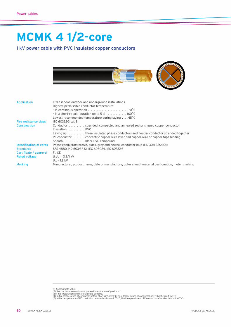
Power cables
30 DRAKA KEILA CABLES PRODUCT CATALOGUE
MCMK 4 1/2-core1 kV power cable with PVC insulated copper conductors
Application Fixed indoor, outdoor and underground installations. Highest permissible conductor temperature: – in continious operation . . . . . . . . . . . . . . . . . . . . . . . . . . 70˚C – in a short circuit (duration up to 5 s) . . . . . . . . . . . . . 160˚C Lowest recommended temperature during laying . . . . -15˚CFire resistance class IEC 60332-3 cat BConstruction Conductor . . . . . . . . . . . stranded, compacted and annealed sector shaped copper conductor Insulation . . . . . . . . . . . PVC Laying up . . . . . . . . . . . three insulated phase conductors and neutral conductor stranded together PE-conductor . . . . . . . . concentric copper wire layer and copper wire or copper tape binding Sheath . . . . . . . . . . . . . . black PVC compoundIdentification of cores Phase conductors brown, black, grey and neutral conductor blue (HD 308 S2:2001) Standards SFS 4880, HD 603-3F S1, IEC 60502-1, IEC 60332-3 Certificate / approval FI, CERated voltage U0/U=0,6/1kV Um=1,2kVMarking Manufacturer, product name, date of manufacture, outer sheath material destignation, meter marking
(1) Approximate value.(2) See the basic assumtions at general information of products.(3) Final installation with careful single bending.(4) Initial temperature of conductor before short circuit 70˚C, final temperature of conductor after short circuit 160˚C.(5) Initial temperature of PE conductor before short circuit 65˚C, final temperature of PE conductor after short circuit 160˚C.
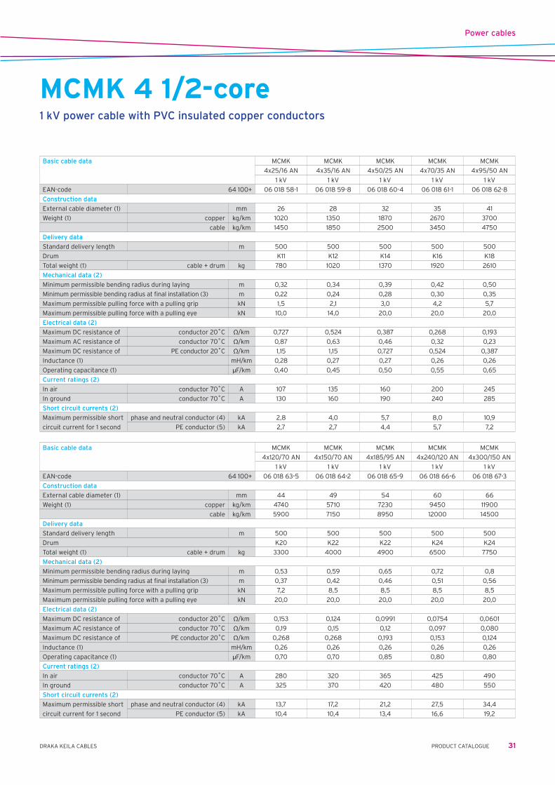
Power cables
31PRODUCT CATALOGUEDRAKA KEILA CABLES
Basic cable data MCMK MCMK MCMK MCMK MCMK
4x25/16 AN 4x35/16 AN 4x50/25 AN 4x70/35 AN 4x95/50 AN
1 kV 1 kV 1 kV 1 kV 1 kV
EAN-code 64 100+ 06 018 58-1 06 018 59-8 06 018 60-4 06 018 61-1 06 018 62-8
Construction data
External cable diameter (1) mm 26 28 32 35 41
Weight (1) copper kg/km 1020 1350 1870 2670 3700
cable kg/km 1450 1850 2500 3450 4750
Delivery data
Standard delivery length m 500 500 500 500 500
Drum K11 K12 K14 K16 K18
Total weight (1) cable + drum kg 780 1020 1370 1920 2610
Mechanical data (2)
Minimum permissible bending radius during laying m 0,32 0,34 0,39 0,42 0,50
Minimum permissible bending radius at final installation (3) m 0,22 0,24 0,28 0,30 0,35
Maximum permissible pulling force with a pulling grip kN 1,5 2,1 3,0 4,2 5,7
Maximum permissible pulling force with a pulling eye kN 10,0 14,0 20,0 20,0 20,0
Electrical data (2)
Maximum DC resistance of conductor 20˚C Ω/km 0,727 0,524 0,387 0,268 0,193
Maximum AC resistance of conductor 70˚C Ω/km 0,87 0,63 0,46 0,32 0,23
Maximum DC resistance of PE conductor 20˚C Ω/km 1,15 1,15 0,727 0,524 0,387
Inductance (1) mH/km 0,28 0,27 0,27 0,26 0,26
Operating capacitance (1) µF/km 0,40 0,45 0,50 0,55 0,65
Current ratings (2)
In air conductor 70˚C A 107 135 160 200 245
In ground conductor 70˚C A 130 160 190 240 285
Short circuit currents (2)
Maximum permissible short phase and neutral conductor (4) kA 2,8 4,0 5,7 8,0 10,9
circuit current for 1 second PE conductor (5) kA 2,7 2,7 4,4 5,7 7,2
Basic cable data MCMK MCMK MCMK MCMK MCMK
4x120/70 AN 4x150/70 AN 4x185/95 AN 4x240/120 AN 4x300/150 AN
1 kV 1 kV 1 kV 1 kV 1 kV
EAN-code 64 100+ 06 018 63-5 06 018 64-2 06 018 65-9 06 018 66-6 06 018 67-3
Construction data
External cable diameter (1) mm 44 49 54 60 66
Weight (1) copper kg/km 4740 5710 7230 9450 11900
cable kg/km 5900 7150 8950 12000 14500
Delivery data
Standard delivery length m 500 500 500 500 500
Drum K20 K22 K22 K24 K24
Total weight (1) cable + drum kg 3300 4000 4900 6500 7750
Mechanical data (2)
Minimum permissible bending radius during laying m 0,53 0,59 0,65 0,72 0,8
Minimum permissible bending radius at final installation (3) m 0,37 0,42 0,46 0,51 0,56
Maximum permissible pulling force with a pulling grip kN 7,2 8,5 8,5 8,5 8,5
Maximum permissible pulling force with a pulling eye kN 20,0 20,0 20,0 20,0 20,0
Electrical data (2)
Maximum DC resistance of conductor 20˚C Ω/km 0,153 0,124 0,0991 0,0754 0,0601
Maximum AC resistance of conductor 70˚C Ω/km 0,19 0,15 0,12 0,097 0,080
Maximum DC resistance of PE conductor 20˚C Ω/km 0,268 0,268 0,193 0,153 0,124
Inductance (1) mH/km 0,26 0,26 0,26 0,26 0,26
Operating capacitance (1) µF/km 0,70 0,70 0,85 0,80 0,80
Current ratings (2)
In air conductor 70˚C A 280 320 365 425 490
In ground conductor 70˚C A 325 370 420 480 550
Short circuit currents (2)
Maximum permissible short phase and neutral conductor (4) kA 13,7 17,2 21,2 27,5 34,4
circuit current for 1 second PE conductor (5) kA 10,4 10,4 13,4 16,6 19,2
MCMK 4 1/2-core1 kV power cable with PVC insulated copper conductors

Power cables
32 DRAKA KEILA CABLES PRODUCT CATALOGUE
MCMOControl cable
Application Cables for control, measuring and signal circuits of electrical equipment for fixed surface or flush-mounted installations, indoors, outdoors and protected underground. The concentric copper conductor forms a good electromechanical protection and a moderate protection against electrical interference.
Maximum permissible temperature of conductor: - in continuous use . . . . . . . . . . . . . . . . . . . . . . . . . . . . . . +70˚C - in a short circuit (max. 5 s) . . . . . . . . . . . . . . . . . . . . . +160˚C Lowest recommended handling temperature . . . . . . . .–15˚C Minimum recommended bending radius: - during installation . . . . . . . . . . . . . . . . . . . . . . . . . . . . . . . . 10D - in a final installation if bent only once . . . . . . . . . . . . . . . 8D Maximum permissible tensile stress during installation Ax50 N/mm2
Construction Conductor . . . . . . . . . . . . . . annealed copper wire Insulation . . . . . . . . . . . . . . black lead-free PVC, core identification by numbers Filling . . . . . . . . . . . . . . . . . . filling compound Concentric conductor . . . . a layer of copper wires and an open helix of parallel copper wires Sheath . . . . . . . . . . . . . . . . . black lead-free PVCStandard SFS 3713Sertificate / approval CE, FI (FIMKO)
Number of conductors and cross-section nxmm2 7 x 1,5 12 x 1,5 19 x 1,5 27 x 1,5 37 x 1,5
EAN code (SSTL-code) 64 100+ 06 019 01-4 06 019 02-1 06 019 03-8 06 019 04-5 06 019 05-2
Nominal overall diameter mm 15 19 22 26 28
Total weight kg/km 350 500 680 900 1150
Direct current resistance at +20˚C max. conductor Ω/km 12,1 12,1 12,1 12,1 12,1
concentric conductor Ω/km 3,08 3,08 3,08 3,08 2,6
Standard delivery length drum m 500/8E 400/8E 500/11G 500/11G 400/11G
Electrical properties
Capacitance between two adjacent conductors at +20˚C and 50 Hz nF/km 130 – 160 130 – 160 130 – 160 130 – 160 130 – 160
Capacitance between one conductor and earth at +20˚C and 50 Hz nF/km 200 – 270 200 – 270 200 – 270 200 – 270 200 – 270
Number of conductors and cross-section nxmm2 7 x 2,5 12 x 2,5 19 x 2,5 27 x 2,5
EAN code (SSTL-code) 64 100+ 06 019 21-2 06 019 22-9 06 019 23-6 06 019 24-3
Nominal overall diameter mm 18 22 25 29
Total weight kg/km 450 690 950 1300
Direct current resistance at +20˚C max. conductor Ω/km 7,41 7,41 7,41 7,41
concentric conductor Ω/km 3,08 3,08 3,08 2,6
Standard delivery length drum m 500/8E 500/11G 500/11G 400/11G
Electrical properties
Capacitance between two adjacent conductors at +20˚C and 50 Hz nF/km 130 – 160 130 – 160 130 – 160 130 – 160
Capacitance between one conductor and earth at +20˚C and 50 Hz nF/km 210 – 280 210 – 280 210 – 280 210 – 280

Power cables
33PRODUCT CATALOGUEDRAKA KEILA CABLES
EX1 kV aerial bundled cable
Application Overhead distribution cable. Highest permissible conductor temperature: – in continious operation . . . . . . . . . . . . . . . . . . . . . . . . . . 70˚C – in a short circuit (duration up to 5 s) . . . . . . . . . . . . . 135˚C Construction Conductor . . . . . . . . . . . round, stranded and compacted aluminium conductor Insulation . . . . . . . . . . . black weather resistant PE compound Laying up . . . . . . . . . . . insulated conductors are stranded togetherIdentification of cores Phase conductors . . . . 1, 2 or 3 longitudinal ridges Neutral conductor . . . . no ridgesStandards HD 626-3ICertificate / approval CERated voltage U0/U=0,6/1kV Um=1,2kVMarking Manufacturer, year of manufacture
Basic cable data EX EX EX EX
2x25 1 kV 4x25 1 kV 4x50 1 kV 4x95 1 kV
Construction data
Insulation thickness mm 1,3 1,3 1,4 1,6
Diameter (1) mm 19 22 28 38
Weight (1) aluminium kg/km 205 405 700 1350
Delivery data
Standard delivery length m 500 500 500 500
Drum K8 K9 K11 K14
Mechanical data (2)
Minimum tensile strenght kN 4,1 4,1 7,3 13,7
Electrical data (2)
Maximum DC resistance of conductor 20˚C Ω/km 1,20 1,20 0,641 0,320

Power cables
34 DRAKA KEILA CABLES PRODUCT CATALOGUE
AMKA1 kV aerial bundled self supporting cable
Application For overhead distribution as part of AMKA-system. Messenger is used as PEN-conductor. The cable can have one optional conductor for street lighting.
Highest permissible conductor temperature: – in continious operation . . . . . . . . . . . . . . . . . . . . . . . . . . 70˚C – in a short circuit (duration up to 5 s) . . . . . . . . . . . . . 135˚C Lowest recommended temperature during laying . . . –20˚CConstruction Conductor . . . . . . . . . . . . . . 16mm2 – round and solid aluminium conductor 25–120mm2 – round, stranded and compacted aluminium conductor Insulation . . . . . . . . . . . . . . black weather resistant PE compound Messenger . . . . . . . . . . . . . round, stranded and compacted aluminium alloy conductor Laying up . . . . . . . . . . . . . . insulated conductors are laid up around the messengerIdentification of cores Phase conductors . . . . . . . 2, 3 or 4 longitudinal ridges Optional conductor . . . . . . no ridgesStandards SFS 2200, HD 626-5D S1 Certificate / approval EEI, FI (SGS FIMKO), CE Rated voltage U0/U=0,6/1kV Um=1,2kVMarking Manufacturer, year of manufacture
Basic cable data AMKA AMKA AMKA AMKA AMKA AMKA AMKA AMKA
1x16+25 3x16+25 4x16+25 3x25+35 3x35+50 3x50+70 3x70+95 3x120+95
1 kV 1 kV 1 kV 1 kV 1 kV 1 kV 1 kV 1 kV
Construction data
Diameter over bare conductor (1) mm 4,4 4,4 4,4 5,8 6,8 8,0 9,6 12,7
Diameter over messenger (1) mm 5,8 5,8 5,8 6,8 8,0 9,6 11,3 11,3
Effective diameter in wind (1) (4) mm 11 20 22 23 27 31 36 42
Weight (1) aluminium kg/km 100 185 225 285 390 540 775 1185
cable kg/km 135 270 330 390 530 700 1000 1500
Delivery data
Standard delivery length m 2000 1000 1000 1000 1000 1000 500 500
Drum K11 K12 K14 K14 K16 K18 K14 K18
Total weight (1) cable + drum kg 325 360 445 505 725 930 695 980
Mechanical data (2)
Minimum permissible bending radius during laying m 0,28 0,42 0,42 0,50 0,58 0,66 0,78 0,92
Minimum permissible bending radius at final installation (3) m 0,20 0,30 0,30 0,35 0,41 0,47 0,55 0,65
Minimum tensile strenght of the messenger kN 7,4 7,4 7,4 10,3 14,2 20,6 27,9 27,9
Initial modulus of elasticity of messenger N/mm2 55000
Final modulus of elasticity of messenger N/mm2 63000
Coefficient of linear expansion of messenger 1/K 23x10-6
Electrical data (2)
Maximum DC resistance of phase conductor 20˚C Ω/km 1,91 1,91 1,91 1,20 0,868 0,641 0,443 0,253
AC resistance of phase (1) conductor 70˚C Ω/km 2,3 2,3 2,3 1,4 1,0 0,77 0,53 0,30
Maximum DC resistance of of messenger conductor 20˚C Ω/km 1,38 1,38 1,38 0,986 0,720 0,493 0,363 0,363
Inductance (1) mH/km 0,29 0,35 0,35 0,34 0,34 0,33 0,31 0,30
Current ratings (2)
In air conductor 70˚C A 75 70 70 95 115 140 180 250
Short circuit currents (2)
Maximum permissible short circuit phase conductor (5) kA 1,0 1,0 1,0 1,6 2,3 3,2 4,5 7,8
current for 1 second (4) messenger (6) kA 1,5 1,5 1,5 2,1 3,0 4,3 5,9 5,9
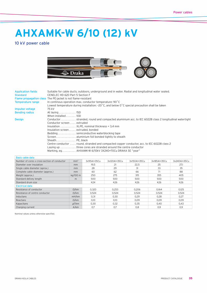
Power cables
35PRODUCT CATALOGUEDRAKA KEILA CABLES
AHXAMK-W 6/10 (12) kV10 kV power cable
Application fields Suitable for cable ducts, outdoors, underground and in water. Radial and longitudinal water sealed.Standard CENELEC HD 620 Part 5 Section FFlame propagation class The PE-jacket is not flame-resistantTemperature range In continous operation max. conductor temperature: 90˚C Lowest temperature during installation: –20˚C, and below 0˚C special precaution shall be takenImpulse voltage 75 kVBending radius At laying . . . . . . . . . . . . 15D When installed . . . . . . . 10DDesign Conductor . . . . . . . . . . . stranded, round and compacted aluminium acc. to IEC 60228 class 2 longitudinal watertight Conductor screen . . . . extruded Insulation . . . . . . . . . . . XLPE,nominalthickness=3,4mm Insulation screen . . . . . extruded, bonded Bedding . . . . . . . . . . . . . semiconductive waterblocking tape Screen . . . . . . . . . . . . . . aluminium foil bonded tightly to sheath Sheath . . . . . . . . . . . . . . PE, black Centre conductor . . . . round, stranded and compacted copper conductor, acc. to IEC 60228 class 2 Laying up . . . . . . . . . . . three cores are stranded around the centre conductor Marking, eg. . . . . . . . . . AHXAMK-W 6/10kV 3X240+70Cu DRAKA SE “year”
Basic cable data
Number of cores x cross-section of conductor mm2 3x95Al+35Cu 3x120Al+35Cu 3x150Al+35Cu 3x185Al+35Cu 3x240Al+35Cu
Diameter over insulation mm 19,5 21 22,5 25 27,1
Single cable diameter (aprox.) mm 28 29 31 33 35
Complete cable diameter (approx.) mm 60 62 66 71 88
Weight (approx.) kg/100 m 250 275 315 355 405
Standard delivey length m 500 500 500 500 500
Standard drum size K24 K26 K26 K26 K26
Electrical data
Resistance of conductor Ω/km 0,320 0,253 0,206 0,164 0,125
Resistance of centre conductor Ω/km 0,524 0,524 0,524 0,524 0,524
Inductans mH/km 0,31 0,30 0,29 0,28 0,27
Reactans Ω/km 0,10 0,10 0,09 0,09 0,09
Kapacitans µF/km 0,30 0,32 0,35 0,40 0,43
Charging current A/km 0,7 0,7 0,8 0,9 0,9
Nominal values unless otherwise specified.

Power cables
36 DRAKA KEILA CABLES PRODUCT CATALOGUE
AHXAMK-W 12/20 (24) kV20 kV power cable
Application fields Suitable for cable ducts, outdoors, underground and in water. Radial and longitudinal water sealed.Standard CENELEC HD 620 Part 5 Section FFlame propagation class The PE-jacket is not flame-resistantTemperature range In continous operation max. conductor temperaure: 90˚C Lowest temperature during installation: –20˚C, and below 0˚C special precaution shall be takenImpulse voltage 125 kVBending radius At laying . . . . . . . . . . . . 15D When installed . . . . . . . 10DDesign Conductor . . . . . . . . . . . stranded, round and compacted aluminium acc. to IEC 60228 class 2 longitudinal watertight Conductor screen . . . . extruded Insulation . . . . . . . . . . . XLPE, nominal thickness 5,5 mm Insulation screen . . . . . extruded, bonded Bedding . . . . . . . . . . . . . semiconductive waterblocking tape Screen . . . . . . . . . . . . . . aluminium foil bonded tightly to sheath Sheath . . . . . . . . . . . . . . PE, black Centre conductor . . . . round, stranded and compacted copper conductor, acc. to IEC 60228 class 2 Laying up . . . . . . . . . . . three cores are stranded around the centre conductor Marking, eg. . . . . . . . . . AHXAMK-W 12/20kV 3X240+70Cu DRAKA SE “year”
Basic cable data
Number of cores x cross-section of conductor mm2 3x50Al+35Cu 3x70Al+35Cu 3x95Al+35Cu 3x120Al+35Cu
Diameter over insulation mm 20,5 22,8 24,5 25,8
Single cable diameter (aprox.) mm 28 29 32 33
Complete cable diameter (approx.) mm 60 65 70 72
Weight (approx.) kg/100 m 240 265 305 330
Standard delivey length m 500 500 500 500
Standard drum size K24 K24 K24 K26
Electrical data
Resistance of conductor Ω/km 0,641 0,443 0,320 0,253
Resistance of centre conductor Ω/km 0,524 0,524 0,524 0,524
Inductans mH/km 0,39 0,42 0,40 0,39
Reactans Ω/km 0,12 0,13 0,13 0,12
Kapacitans µF/km 0,16 0,18 0,21 0,22
Charging current A/km 0,7 0,7 0,8 0,8
Basic cable data
Number of cores x cross-section of conductor mm2 3x150Al+35Cu 3x185Al+35Cu 3x240Al+35Cu 3x240Al+70Cu
Diameter over insulation mm 26,6 29,0 30,5 31,3
Single cable diameter (aprox.) mm 34 36 39 39
Complete cable diameter (approx.) mm 75 80 86 88
Weight (approx.) kg/100 m 375 420 500 530
Standard delivey length m 500 500 500 500
Standard drum size K26 K26 K28 K28
Electrical data
Resistance of conductor Ω/km 0,206 0,164 0,125 0,125
Resistance of centre conductor Ω/km 0,524 0,524 0,524 0,268
Inductans mH/km 0,37 0,36 0,35 0,35
Reactans Ω/km 0,12 0,11 0,11 0,11
Kapacitans µF/km 0,24 0,26 0,29 0,29
Charging current A/km 0,9 1,0 1,1 1,1

Power cables
37PRODUCT CATALOGUEDRAKA KEILA CABLES
Basic cable data
Number of cores x cross-section of conductor mm2 1x50/16 1x95/16 1x150/25 1x240/25
Diameter over insulation mm 16,0 19,3 22,2 26,1
Overall diameter (approx.) mm 23,3 26,6 29,7 33,8
Weight (approx.) kg/100 m 59,7 79,4 107,4 141,4
Standard deliverylength m 500 500 500 500
Standard drum size K11 K12 K12 K14
Article-number 0070410 0070420 0070440 0070460
Electrical data at +20˚C
Conductor resistance Ω/km 0,641 0,320 0,206 0,125
Screen resistance Ω/km 1,2 1,2 0,8 0,8
Inductance in trefoil/inplane *) mH/km 0,40/0,73 0,36/0,66 0,34/0,63 0,31/0,58
Reactance Ω/km 0,29 0,21 0,20 0,18
Capacitance µF/km 0,23 0,30 0,35 0,43
Charging current A/km 1,5 2,0 2,3 2,8
Electrical data
Current rating at core temp.65 ºC in ground *) A 170 250 315 395
Current rating at core temp. 65 ºCin air *) A 165 255 325 420
Current rating at core temp. 90 ºCin air *) A 205 310 395 515
Max. short-circuit current on the conductor during 1 s at initial temp. 70 ºC kA 5,1 9,7 15,3 24,4
Max. short-circuit current on the conductor during 1 s at initial temp. 90ºC kA 4,7 9,0 14,2 22,7
*)Cabledistance,installationinplane=70mm.Trefoil with screen grounded in both ends.Nominal values unless otherwise specified.
AXLJ-TT 7/12 kV10 kV power cable
Application fields Single-core distribution cable suitable for laying outdoors in 1- or 3-phase formation. Installation in pipes and in ground/water. Both radial and longitudinal water sealed. Can be ploughed down.
Alternative designation SE-N10XC7A5T5E-ARStandard SS 424 14 16 CENELEC HD 620 Part 5 Section MFire propagation class F1 acc. to SS 424 14 75Temperature range In continuous operation max. conductor temp. 90 ºC. Lowest cable temperature under installation: –20 ºC and below 0ºC special precaution shall be taken.Material declaration AXLJ-TTImpulse voltage 75 kVBending radius At fixed mounting . . . . . . . . . 10D At pulling-in . . . . . . . . . . . . . . 15D At ploughing-down . . . . . . . . 8DDesign Conductor . . . . . . . . . . . . . . . . stranded, round and compacted aluminium acc. to IEC 60228 class 2,
longitudinal water sealed Conductor screen . . . . . . . . . extruded Insulation . . . . . . . . . . . . . . . . XLPE,min.thickness=2,96mm Insulation screen . . . . . . . . . . extruded bonded Longitudinal water sealing. . swellable conducting tape Concentric conductor . . . . . . annealed copper wires Radial water sealing . . . . . . . aluminium-PE laminate Sheath . . . . . . . . . . . . . . . . . . . LLD PE, black Marking e.g. . . . . . . . . . . . . . . AXLJ-TT 08DRAKA TSLE 12kV 1X240 AFR/25 “Date”, metre marked.

Power cables
38 DRAKA KEILA CABLES PRODUCT CATALOGUE
AXLJ-TT 14/24 kV20 kV power cable
Application fields Single-core, distribution cable for outdoors use in 3-phase formation. Installation in pipes and ground/water. Both radial and longitudinal water sealed. Can be ploughed down.
Alternative designation SE-N20XC7A5T5E-ARStandard CENELEC HD 620 Part 5 Section KFire propagation class F1 acc. to SS 424 14 75Temperature range In continuous operation max. conductor temp: 90˚C. Lowest cable temperature under installation: –20˚C and below 0˚C special precaution shall be taken.Material declaration AXLJ-TTImpulse voltage 125 kVBending radius At fixed mounting . . . . . . . . .10D At pulling-in . . . . . . . . . . . . . .15D At ploughing-down . . . . . . . .8DDesign Conductor . . . . . . . . . . . . . . . .stranded, round and compacted aluminium acc. to IEC 60228 class 2,
longitudinal water sealed Conductor screen . . . . . . . . .extruded Insulation . . . . . . . . . . . . . . . .XLPE,min.thickness=4,85mm Insulation screen . . . . . . . . . .extruded bonded Longitudinal water sealing. .swellable conducting tape Concentric conductor . . . . . .annealed copper wires Radial water sealing . . . . . . .aluminium-PE laminate Sheath . . . . . . . . . . . . . . . . . . .LLD PE, black Marking e.g. . . . . . . . . . . . . . .AXLJ-TT 08DRAKA TSLE 24kV 1X150 AFR/25 “Year”, metre marked
*)Cabledistance,installationinplane=70mm*) Trefoil with screen grounded in both endsNominal values unless otherwise specified.
Basic cable data
Number of cores x cross-section of conductor mm2 1x50/16 1x95/16 1x150/25 1x240/25
Diameter over insulation mm 20,4 23,7 26,6 30,5
Overall diameter (approx.) mm 27,7 31,2 34,3 38,6
Weight (approx.) kg/100 m 70,6 98,5 120,5 165,2
Standard deliverylength m 500 500 500 500
Standard drum size K12 K12 K14 K16
Article-number 1205011702 0070520 1205012102 0070560
Electrical data at +20˚C
Conductor resistance Ω/km 0,641 0,320 0,206 0,125
Screen resistance Ω/km 1,2 1,2 0,8 0,8
Inductance in trefoil/inplane *) mH/km 0,44/0,74 0,39/0,67 0,37/0,63 0,34/0,59
Reactance Ω/km 0,23 0,21 0,20 0,19
Capacitance µF/km 0,17 0,20 0,24 0,29
Charging current A/km 2,2 2,6 3,2 3,8
Electrical data
Current rating at core temp.65 ºC in ground *) A 170 250 315 395
Current rating at core temp. 65 ºCin air *) A 165 255 325 420
Current rating at core temp. 90 ºCin air *) A 205 310 395 515
Max. short-circuit current on the conductor during 1 s at initial temp. 70 ºC kA 5,1 9,7 15,3 24,4
Max. short-circuit current on the conductor during 1 s at initial temp. 90ºC kA 4,7 9,0 14,2 22,7

Power cables
39PRODUCT CATALOGUEDRAKA KEILA CABLES
AXLJ-TTCL TSLF 14/24 kV
Application fields Single-core and 3-core, distribution cable for outdoors use in 3-phase formation. Installation in pipes and ground/water. Both radial and longitudinal water sealed. Can be ploughed down. Possibility for electric testing of sheath and detecting of damagees due to semiconductive outer layer.
Alternative designation SE-N20XC7A5T5E-ARStandard CENELEC HD 620 Part 5 Section KFire propagation class F1 acc. to SS 424 14 75Temperature range In continuous operation max. conductor temp 90 ºC. Lowest cable temperature during laying -20 ºC and below 0 ºC special precaution shall be taken.Material declaration AXLJ-TTImpulse voltage 125 kVBending radius At fixed mounting . . . . . . . . 10D At pulling-in . . . . . . . . . . . . . 15D At ploughing-down . . . . . . . 8DDesign Conductor . . . . . . . . . . . . . . . Stranded, round and compacted aluminium acc. to IEC 60228 class 2, longitudinal water sealed Conductor screen . . . . . . . . Extruded Insulation . . . . . . . . . . . . . . . XLPE,nom.thickness=5,5mm Insulation screen . . . . . . . . . Extruded bonded Longitudinal water sealing . . Swellable conducting tape Concentric conductor . . . . . Annealed copper wires Radial water sealing . . . . . . Aluminium-PE laminate, bonded to sheath Sheath . . . . . . . . . . . . . . . . . . LLD PE, natural Semiconductive layer . . . . . Extruded bonded to the outher sheath, black Laying up 3-core . . . . . . . . . Three stranded singel-core cables Marking e.g. . . . . . . . . . . . . . AXLJ-TTCL 08DRAKA TSLF 24kV 1X150 AFR/25 “Year”, metre marked
Number of cores x crosssection of conductor mm2 1x50/16 1x95/25 1x150/25 1x240/35 1x400/35 3x1x50/16 3x1x95/25 3x1x150/25 3x1x240/35
Diameter over insulation mm 20,4 23,7 26,6 30,5 36,0 20,4 23,7 26,6 30,5
Thicknes of sheath mm 1,8 1,9 2,0 2,2 2,3 1,8 1,9 2,0 2,2
Overall diameter (approx.) mm 29 32 35 40 45 60 69 75 84
Weight (approx.) kg/100 m 71 100 121 167 228 210 295 360 510
Standard delivery length m 500 500 500 500 500 500 500 500 500
Standard drum size K12 K12 K14 K16 K18 K24 K26 K26 K28
Electrical data at +20 °C
Conductor resistance Ω/km 0,641 0,320 0,206 0,125 0,0778 0,641 0,320 0,206 0,125
Screen resistance Ω/km 1,15 0,727 0,727 0,524 0,524 1,15 0,727 0,727 0,524
Inductance in trefoil/in plane * mH/km 0,44/0,74 0,39/0,67 0,37/0,63 0,34/0,59 0,32/0,55 0,44 0,39 0,37 0,34
Reactance in trefoil/in plane * Ω/km 0,14/0,23 0,12/0,21 0,12/0,20 0,11/0,19 0,10/0,17 0,14 0,12 0,12 0,11
Capacitance μF/km 0,17/0,6 0,20/0,8 0,24/0,9 0,29/1,1 0,36/1,4 0,17 0,20 0,24 0,29
Charging current/phase A/km 0,6 0,8 0,9 1,1
Current ratings
Current rating at core
temp. 65 ºC in ground ** A 170 250 315 395 525 170 250 315 395
temp. 65 ºC in air ** A 160 230 300 400 555 160 230 300 400
temp. 90 ºC in air ** A 195 280 370 490 680 195 280 370 490
Max. short-circuit current on the conductor
during 1 s at initial temp. 65 ºC kA 5,2 9,9 15,6 25,0 41,6 5,2 9,9 15,6 25,0
during 1 s at initial temp. 90 ºC kA 4,7 8,9 14,2 22,7 37,8 4,7 8,9 14,2 22,7
* Cabledistance,installationinplane=70mm
** Trefoil with screen grounded in both ends

Power cables
40 DRAKA KEILA CABLES PRODUCT CATALOGUE
AXLJ-TT 7/12 kV (3-core)10 kV power cable
Application fields 3-core cable designed for replacement of bare overhead lines outdoors. Primary developed to be ploughed down but thanks to the robust design the cable can stand the stresses that appears when laying in lake with calm water and limited deep. The design with water swellable yarn and aluminium foil bonded to the sheath makes the cable radial and longitudinal water sealed.
Alternative designation SE-N10XC7A5T5E-ARStandard SS 424 14 16 CENELEC HD 620 Part 6 Section MFire propagation class F1 acc. to SS 424 14 75Temperature range In continuous operation max. conductor temp 90˚C. Lowest cable temperature under installation: –20˚C and below 0˚C special precaution shall be taken.Material declaration AXLJ-TTImpulse voltage 75 kVBending radius At fixed mounting . . . . . . . .8D At pulling-in . . . . . . . . . . . . .12D At ploughing-down . . . . . . .8DDesign Conductor . . . . . . . . . . . . . . . . . stranded, round and compacted aluminium acc. to IEC 60228 class 2, longitudinal water sealed Conductor screen . . . . . . . .extruded Insulation . . . . . . . . . . . . . . .XLPE,min.thickness=2,96mm Insulation screen . . . . . . . . .extruded bonded Longitudinal water sealing . .swellable conducting tape and water swellable yarn Concentric conductor . . . . .annealed copper wires Radial water sealing . . . . . .aluminium foil bonded to the sheath Sheath . . . . . . . . . . . . . . . . . .LLD PE, black Marking e.g. . . . . . . . . . . . . .AXLJ-TT 7/12kV 3X95/16 DRAKA SE “Date”, metre marked
Nominal values unless otherwise specified.
Basic cable data
Number of cores x cross-section of conductor mm2 3x25/16 3x50/16 3x95/16 3x150/25 3x240/25
Diameter over insulation mm 13,9 16,0 19,3 22,2 26,1
Overall diameter single core (approx.) mm 14,9 17 20,3 23,2 27,1
Overall diameter whole cable (approx.) mm 37,6 42,3 49,8 56,7 65,5
Weight (approx.) kg/100 m 108,1 142,0 202,9 279,3 384,2
Standard deliverylength m 500 500 500 500 500
Standard drum size K16 K18 K20 K22 K24
Article-number 0071000 0071010 0071020 0071030 0071040
Electrical data at +20˚C
Conductor resistance Ω/km 1,2 0,641 0,320 0,206 0,125
Screen resistance Ω/km 1,2 1,2 1,2 0,8 0,8
Inductance in trefoil/inplane *) mH/km 0,37 0,34 0,31 0,29 0,27
Reactance Ω/km 0,12 0,11 0,10 0,09 0,09
Capacitance µF/km 0,19 0,23 0,30 0,35 0,43
Charging current A/km 1,3 1,5 2,0 2,3 2,8
Electrical data
Current rating at core temp. 65 ºC in ground *) A 100 145 205 260 340
Current rating at core temp. 65 ºCin air *) A 90 130 190 250 330
Current rating at core temp. 90 ºCin air *) A 110 160 230 305 400
Max. short-circuit current on the conductor during 1 s at initial temp. 70 ºC kA 2,5 5,1 9,7 15,3 24,4
Max. short-circuit current on the conductor during 1 s at initial temp. 90ºC kA 2,3 4,7 9,0 14,2 22,7
Max. impulse current kA - 55 65 70 70

Power cables
41PRODUCT CATALOGUEDRAKA KEILA CABLES
AXLJ-TT 14/24 kV (3-core)20 kV power cable
Application fields 3-core cable designed for replacement of bare overhead lines outdoors. Primary developed to be ploughed down but thanks to the robust design the cable can stand the stresses that appears when laying in lake with calm water and limited deep. The design with water swellable yarn and aluminium foil bonded to the sheath makes the cable radial and longitudinal water sealed.
Alternative designation SE-N20XC7A5T5E-ARStandard CENELEC HD 620 Part 6 Section KFire propagation class F1 acc. to SS 424 14 75Temperature range In continuous operation max. conductor temp 90˚C. Lowest cable temperature under installation –20˚C and below 0˚C special precaution shall be taken.Material declaration AXLJ-TTImpulse voltage 125 kVBending radius At fixed mounting . . . . . . . . . . . 8D At pulling-in . . . . . . . . . . . . . . . . 12D At ploughing-down . . . . . . . . . . 8DDesign Conductor . . . . . . . . . . . . . . . . . . stranded, round and compacted aluminium acc. to IEC 60228 class 2,
longitudinal water sealed Conductor screen . . . . . . . . . . . extruded Insulation . . . . . . . . . . . . . . . . . .XLPE,min.thickness=4,85mm Insulation screen . . . . . . . . . . . . extruded bonded Longitudinally water sealed. . . swellable conducting tape and water swellable yarn Sheath . . . . . . . . . . . . . . . . . . . . . annealed copper wires Radial water sealing . . . . . . . . . aluminium foil bonded to the sheath Sheath . . . . . . . . . . . . . . . . . . . . . LLD PE, black Marking e.g. . . . . . . . . . . . . . . . . AXLJ-TT 14/24 kV 3x95/16 DRAKA SE “Date”, metre marked
Nominal values unless otherwise specified.
Basic cable data
Number of cores x cross-section of conductor mm2 3x25/16 3x50/16 3x95/16 3x150/25 3x240/25
Diameter over insulation mm 18,1 20,2 23,5 26,4 30,3
Overall diameter single core (approx.) mm 18,9 21,0 24,3 27,2 31,1
Overall diameter whole cable (approx.) mm 47,2 52,2 59,7 66,3 75,3
Weight (approx.) kg/100 m 155,4 194,6 266,9 344,2 461,5
Standard deliverylength m 500 500 500 500 500
Standard drum size K20 K20 K24 K24 K26
Article-number 0071050 0071060 0071070 0071080 0071090
Electrical data at +20˚C
Conductor resistance Ω/km 1,2 0,641 0,320 0,206 0,125
Screen resistance Ω/km 1,2 1,2 1,2 0,8 0,8
Inductance in trefoil/inplane mH/km 0,42 0,38 0,34 0,32 0,30
Reactance Ω/km 0,13 0,12 0,11 0,10 0,09
Capacitance µF/km 0,14 0,17 0,20 0,24 0,29
Charging current A/km 1,8 2,2 2,6 3,2 3,8
Electrical data
Current rating at core temp. 65 ºC in ground A 100 145 205 260 340
Current rating at core temp. 65 ºCin air A 90 130 190 250 330
Current rating at core temp. 90 ºCin air A 110 160 230 305 400
Max. short-circuit current on the conductor during 1 s at initial temp. 70 ºC kA 2,5 5,1 9,7 15,3 24,4
Max. short-circuit current on the conductor during 1 s at initial temp. 90ºC kA 2,3 4,7 9,0 14,2 22,7
Max. impulse current kA - 55 65 70 70
Basic cable data
Number of cores x cross-section of conductor mm2 3x25/16 3x50/16 3x95/16 3x150/25 3x240/25
Diameter over insulation mm 13,9 16,0 19,3 22,2 26,1
Overall diameter single core (approx.) mm 14,9 17 20,3 23,2 27,1
Overall diameter whole cable (approx.) mm 37,6 42,3 49,8 56,7 65,5
Weight (approx.) kg/100 m 108,1 142,0 202,9 279,3 384,2
Standard deliverylength m 500 500 500 500 500
Standard drum size K16 K18 K20 K22 K24
Article-number 0071000 0071010 0071020 0071030 0071040
Electrical data at +20˚C
Conductor resistance Ω/km 1,2 0,641 0,320 0,206 0,125
Screen resistance Ω/km 1,2 1,2 1,2 0,8 0,8
Inductance in trefoil/inplane *) mH/km 0,37 0,34 0,31 0,29 0,27
Reactance Ω/km 0,12 0,11 0,10 0,09 0,09
Capacitance µF/km 0,19 0,23 0,30 0,35 0,43
Charging current A/km 1,3 1,5 2,0 2,3 2,8
Electrical data
Current rating at core temp. 65 ºC in ground *) A 100 145 205 260 340
Current rating at core temp. 65 ºCin air *) A 90 130 190 250 330
Current rating at core temp. 90 ºCin air *) A 110 160 230 305 400
Max. short-circuit current on the conductor during 1 s at initial temp. 70 ºC kA 2,5 5,1 9,7 15,3 24,4
Max. short-circuit current on the conductor during 1 s at initial temp. 90ºC kA 2,3 4,7 9,0 14,2 22,7
Max. impulse current kA - 55 65 70 70

Power cables
42 DRAKA KEILA CABLES PRODUCT CATALOGUE
AXLJ-RMF 7/12 kV10 kV power cable
Application fields 3-core cable designed for replacement of bare overhead lines outdoors. Primary developed to be ploughed down but thanks to the robust design it can stand the stresses that appears when laying in water.
Alternative designation SE-N10XC7V-ARStandard S 424 14 16 CENELEC HD 620 Part 6 Section MFire propagation class F1 acc. to SS 424 14 75Temperature range In continuous operation max. conductor temp 90˚C. Lowest cable temperature under installation: -20˚C and below 0˚C special precaution shall be taken.Material declaration AXLJ LT, -F, -RMFImpulse voltage 75 kVBending radius At fixed mounting . . . . . .8D At pulling-in . . . . . . . . . . .12D At ploughing-down . . . . .8DDesign Conductor . . . . . . . . . . . . .stranded, round and compacted aluminium acc. to IEC 60228 class 2, longitudinal water sealed Conductor screen . . . . . .extruded Insulation . . . . . . . . . . . . .XLPE,min.thickness=2,96mm Insulation screen . . . . . . .extruded bonded Taping . . . . . . . . . . . . . . . .conductive tape Concentric conductor . . .snnealed copper wires Sheath . . . . . . . . . . . . . . . .LLD PE, black Marking e.g. . . . . . . . . . . .AXLJ-RMF 7/12 KV 3X150/25 LT DRAKA SE “year”
Nominal values unless otherwise specified.
Basic cable data
Number of cores x cross-section of conductor mm2 3x25/16 3x50/16 3x95/16 3x150/25 3x240/25
Diameter over insulation mm 14,0 16,2 19,5 22,4 26,3
Overall diameter (approx.) mm 39,1 44,0 51,6 58,4 67,2
Weight (approx.) kg/100 m 103,5 135,4 195,1 267,1 372,8
Standard deliverylength m 500 500 500 500 500
Standard drum size K16 K18 K20 K22 K24
Article-number 1040031502 1040031702 1040031902 1040032102 1040032302
Electrical data at +20˚C
Conductor resistance Ω/km 1,2 0,641 0,320 0,206 0,125
Screen resistance Ω/km 1,2 1,2 1,2 0,8 0,8
Inductance in trefoil/inplane mH/km 0,38 0,34 0,31 0,29 0,27
Reactance Ω/km 0,12 0,11 0,10 0,09 0,09
Capacitance µF/km 0,19 0,23 0,30 0,35 0,42
Charging current A/km 1,3 1,5 2,0 2,4 2,9
Electrical data
Current rating at core temp. 65 ºC in ground A 100 145 205 260 340
Current rating at core temp. 65 ºCin air A 90 130 190 250 330
Current rating at core temp. 90 ºCin air A 110 160 230 305 400
Max. short-circuit current on the conductor during 1 s at initial temp. 70 ºC kA 2,5 5,1 9,7 15,3 24,4
Max. short-circuit current on the conductor during 1 s at initial temp. 90ºC kA 2,3 4,7 9,0 14,2 22,7
Max. impulse current kA - 55 65 70 70

Power cables
43PRODUCT CATALOGUEDRAKA KEILA CABLES
AXLJ-RMF 14/24 kV20 kV power cable
Application fields 3-core cable designed for replacement of bare overhead lines outdoors. Primary developed to be ploughed down but thanks to the robust design it can stand the stresses that appears when laying in water.
Alternative designation SE-N20XC7V-ARStandard S 424 14 16 CENELEC HD 620 Part 6 Section MFire propagation class F1 acc. to SS 424 14 75Temperature range In continuous operation max. conductor temp 90˚C. Lowest cable temperature under installation: -20˚C and below 0˚C special precaution shall be taken.Material declaration AXLJ LT, -F, -RMFImpulse voltage 125 kVBending radius At fixed mounting . . . . . 8D At pulling-in . . . . . . . . . . 12D At ploughing-down . . . . 8DDesign Conductor . . . . . . . . . . . . stranded, round and compacted aluminium acc. to IEC 60228 class 2, longitudinal water sealed Conductor screen . . . . . extruded Insulation . . . . . . . . . . . . XLPE,min.thickness=4,85mm Insulation screen . . . . . . extruded bonded Taping . . . . . . . . . . . . . . . conductive tape Concentric conductor . . annealed copper wires Sheath . . . . . . . . . . . . . . . LLD PE, black Marking e.g. . . . . . . . . . . AXLJ-RMF 14/24 KV 3X150/25 LT DRAKA SE “year”
Nominal values unless otherwise specified.
Basic cable data
Number of cores x cross-section of conductor mm2 3x25/16 3x50/16 3x95/16 3x150/25 3x240/25
Diameter over insulation mm 18,2 20,4 23,7 26,7 30,7
Overall diameter (approx.) mm 49,0 53,9 61,4 68,1 77,1
Weight (approx.) kg/100 m 147,2 185,1 253,9 328,1 445,5
Standard delivery length m 500 500 500 500 500
Standard drum size K20 K20 K24 K24 K26
Article-number 1045031502 1045031702 1045031902 1045032102 1045032302
Electrical data at +20˚C
Conductor resistance Ω/km 1,2 0,641 0,320 0,206 0,125
Screen resistance Ω/km 1,2 1,2 1,2 0,8 0,8
Inductance in trefoil/inplane mH/km 0,43 0,39 0,35 0,32 0,30
Reactance Ω/km 0,14 0,12 0,11 0,10 0,09
Capacitance µF/km 0,14 0,16 0,20 0,24 0,29
Charging current A/km 1,8 2,1 2,6 3,2 3,8
Electrical data
Current rating at core temp. 65 ºC in ground A 100 145 205 260 340
Current rating at core temp. 65 ºCin air A 90 130 190 250 330
Current rating at core temp. 90 ºCin air A 110 160 230 305 400
Max. short-circuit current on the conductor during 1 s at initial temp. 70 ºC kA 2,5 5,1 9,7 15,3 24,4
Max. short-circuit current on the conductor during 1 s at initial temp. 90ºC kA 2,3 4,7 9,0 14,2 22,7
Max. impulse current kA - 55 65 70 70

Power cables
44 DRAKA KEILA CABLES PRODUCT CATALOGUE
AXQJ-RMF 7/12 kV10 kV halogen-free power cable
Application fields Halogen free and fire classified cable. No emittance of corrosive gases, low smoke density in case of fire. Primary developed for installation indoors, tunnels etc. The cable can also with advantage be installed outdoors and in ground. Ploughing down is not recommended.
Alternative designation SE-N10XC7Z1-ARStandard SS 424 14 16 CENELEC HD 620 Part 6 Section M CENELEC HD 604 (Halogen free materials) IEC 60754-1, –2 (corrosive gases) IEC 61034 (smoke density)Fire propagation class F4B acc. to SS 424 14 75 and IEC 60332-3 cat B and SS-EN 50266-2-3Temperature range In continuous operation max. conductor temp 90˚C. Lowest cable temperature under installation: –20˚C and below 0˚C special precaution shall be taken.Material declaration AXQJ-F, –RMFImpulse voltage 75 kVBending radius At fixed mounting . . . . . 8D At pulling-in . . . . . . . . . . 12D At ploughing-down . . . . 8DDesign Conductor . . . . . . . . . . . . stranded, round and compacted aluminium acc. to IEC 60228 class 2, longitudinal water sealed Conductor screen . . . . . extruded Insulation . . . . . . . . . . . . XLPE,min.thickness=2,96mm Insulation screen . . . . . . extruded bonded Taping . . . . . . . . . . . . . . . conductive tape Concentric conductor . . annealed copper wires Sheath . . . . . . . . . . . . . . . halogen free compound, black Marking e.g. . . . . . . . . . . AXQJ-RMF 7/12 kV 3x150/25 LT F4B DRAKA SE “Date”, metre marked
Nominal values unless otherwise specified.
Basic cable data
Number of cores x cross-section of conductor mm2 3x50/16 3x95/16 3x150/25 3x240/25
Diameter over insulation mm 16,0 19,3 22,2 26,1
Overall diameter (approx.) mm 43,6 51,1 58,0 66,8
Weight (approx.) kg/100 m 153,2 219,4 297,3 405,3
Standard delivery length m 500 500 500 500
Standard drum size K18 K20 K22 K24
Article-number 0071210 0071220 0071230 0071240
Electrical data at +20˚C
Conductor resistance Ω/km 0,641 0,320 0,206 0,125
Screen resistance Ω/km 1,2 1,2 0,8 0,8
Inductance in trefoil/inplane mH/km 0,34 0,31 0,29 0,27
Reactance Ω/km 0,11 0,10 0,09 0,09
Capacitance µF/km 0,23 0,30 0,35 0,43
Charging current A/km 1,5 2,0 2,3 2,8
Electrical data
Current rating at core temp. 65 ºC in ground A 145 205 260 340
Current rating at core temp. 65 ºCin air A 130 190 250 330
Current rating at core temp. 90 ºCin air A 160 230 305 400
Max. short-circuit current on the conductor during 1 s at initial temp. 70 ºC kA 5,1 9,7 15,3 24,4
Max. short-circuit current on the conductor during 1 s at initial temp. 90ºC kA 4,7 9,0 14,2 22,7
Max. impulse current kA 55 65 70 70

Power cables
45PRODUCT CATALOGUEDRAKA KEILA CABLES
AXQJ-RMF 14/24 kV20 kV halogen-free power cable
Application fields Halogen free and fire classified cable. No emittance of corrosive gases, low smoke density in case of fire. Primary developed for installation indoors, tunnels etc. The cable can also with advantage be installed outdoors and in ground. Ploughing down is not recommended.
Alternative designation SE-N20XC7Z1-ARStandard SS 424 14 16 CENELEC HD 620 Part 6 Section M CENELEC HD 604 (Halogen free materials) IEC 60754-1, –2 (corrosive gases) IEC 61034 (smoke density)Fire propagation class F4B acc. to SS 424 14 75 and IEC 60332-3 cat B and SS-EN 50266-2-3Temperature range In continuous operation max. conductor temp 90˚C. Lowest cable temperature under installation: –20˚C and below 0˚C special precaution shall be taken.Material declaration AXQJ-F, –RMFImpulse voltage 125 kVBending radius At fixed mounting . . . . . 8D At pulling-in . . . . . . . . . . 12D At ploughing-down . . . . 8DDesign Conductor . . . . . . . . . . . . stranded, round and compacted aluminium acc. to IEC 60228 class 2, longitudinal water sealed Conductor screen . . . . . extruded Insulation . . . . . . . . . . . . XLPE,min.thickness=4,85mm Insulation sreen . . . . . . . extruded bonded Taping . . . . . . . . . . . . . . . conductive tape Concentric conductor . . annealed copper wires Sheath . . . . . . . . . . . . . . . halogen free compound, black Marking e.g. . . . . . . . . . . AXQJ-RMF 14/24 kV 3x150/25 LT F4B DRAKA SE “Date”, metre marked.
Nominal values unless otherwise specified.
Basic cable data
Number of cores x cross-section of conductor mm2 3x50/16 3x95/16 3x150/25 3x240/25
Diameter over insulation mm 20,2 23,5 26,4 30,3
Overall diameter (approx.) mm 53,5 61,0 67,6 76,6
Weight (approx.) kg/100 m 210,2 286,2 367,0 488,3
Standard delivery length m 500 500 500 500
Standard drum size K20 K24 K24 K26
Article-number 0071250 0071260 0071270 0071280
Electrical data at +20˚C
Conductor resistance Ω/km 0,641 0,320 0,206 0,125
Screen resistance Ω/km 1,2 1,2 0,8 0,8
Inductance in trefoil/inplane mH/km 0,38 0,34 0,32 0,30
Reactance Ω/km 0,12 0,11 0,10 0,09
Capacitance µF/km 0,17 0,20 0,24 0,29
Charging current A/km 2,2 2,6 3,2 3,8
Electrical data
Current rating at core temp. 65 ºC in ground A 145 205 260 340
Current rating at core temp. 65 ºCin air A 130 190 250 330
Current rating at core temp. 90 ºCin air A 160 230 305 400
Max. short-circuit current on the conductor during 1 s at initial temp. 70 ºC kA 5,1 9,7 15,3 24,4
Max. short-circuit current on the conductor during 1 s at initial temp. 90ºC kA 4,7 9,0 14,2 22,7
Max. impulse current kA 55 65 70 70

Power cables
46 DRAKA KEILA CABLES PRODUCT CATALOGUE
AXQJ-F 7/12 kV10 kV halogen-free power cable
Application fields Halogen free and fire classified single-core cable. No emittance of corrosive gases, low smoke density in case of fire. Distribution cable for indoors and outdoors use in 3-phase formation. Installation in pipes and ground. Ploughing down is not recommended.
Alternative designation SE-N10XC7Z1-ARStandard SS 424 14 16 CENELEC HD 620 Part 5 Section M CENELEC HD 604 (Halogen free materials) IEC 60754-1, –2 (corrosive gases) IEC 61034 (smoke density)Fire propagation class F4B acc. to SS 424 14 75 and IEC 60332-3 cat B and SS-EN 50266-2-3Temperature range In continuous operation max. conductor temp 90˚C. Lowest cable temperature under installation –20˚C and below 0˚C special precaution shall be taken.Material declaration AXQJ-F, –RMFImpulse voltage 75 kVBending radius At fixed mounting . . . . . 10D At pulling-in . . . . . . . . . . 15D At ploughing-down . . . . 8DDesign Conductor . . . . . . . . . . . . stranded, round and compacted aluminium acc. to IEC 60228 class 2
240 mm2 is longitudinal water sealed Conductor screen . . . . . extruded Insulation . . . . . . . . . . . . XLPE,min.thickness=2,96mm Insulation screen . . . . . . extruded bonded Concentric conductor . . annealed copper wires Sheath . . . . . . . . . . . . . . . halogen free compound, black Marking e.g. . . . . . . . . . . AXQJ-F 7/12 kV 1x630/35 F4B FASTSITTANDE SKIKT DRAKA SE “Date”, metre marked
Basic cable data
Number of cores x cross-section of conductor mm2 1x240/25 1x500/35 1x630/35
Diameter over insulation mm 26,1 34,6 38,7
Overall diameter (approx.) mm 33,5 42,7 46,9
Weight (approx.) kg/100 m 149,4 254,9 302,4
Standard delivery length m 500 500 500
Standard drum size K14 K18 K20
Article-number 0071340 0071370 0071380
Electrical data at +20˚C
Conductor resistance Ω/km 0,125 0,0605 0,0469
Screen resistance Ω/km 0,8 0,6 0,6
Inductance in trefoil/in plane *) mH/km 0,31/0,58 0,28/0,52 0,27/0,50
Reactance Ω/km 0,18 0,16 0,16
Capacitance µF/km 0,43 0,59 0,67
Charging current A/km 2,8 3,9 4,4
Electrical data
Current rating at core temp. 65 ºC in ground *) A 385 570 635
Current rating at core temp. 65 ºCin air *) A 400 635 720
Current rating at core temp. 90 ºCin air *) A 490 775 880
Max. short-circuit current on the conductor during 1 s at initial temp. 70 ºC kA 24,4 50,9 64,1
Max. short-circuit current on the conductor during 1 s at initial temp. 90ºC kA 22,7 47,2 59,5
*)Cabledistance,installationinplane=70mm*) Trefoil with screen grounded in both endsNominal values unless otherwise specified.

Power cables
47PRODUCT CATALOGUEDRAKA KEILA CABLES
AXQJ-F 14/24 kV20 kV halogen-free power cable
Application fields Halogen free and fire classified single-core cable. No emittance of corrosive gases, low smoke density in case of fire. Distribution cable for indoors and outdoors use in 3-phase formation. Installation in pipes and ground. Ploughing down is not recommended.
Alternative designation SE-N20XC7Z1-ARStandard SS 424 14 16 CENELEC HD 620 Part 5 Section M CENELEC HD 604 (Halogen free materials) IEC 60754-1, –2 (corrosive gases) IEC 61034 (smoke density)Fire propagation class F4B acc. to SS 424 14 75 and IEC 60332-3 cat B and SS-EN 50266-2-3Temperature range In continuous operation max. conductor temp 90˚C. Lowest cable temperature under installation: –20˚C and below 0˚C special precaution shall be taken.Material declaration AXQJ-F, –RMFImpulse voltage 125 kVBending radius At fixed mounting . . . . . .10D At pulling-in . . . . . . . . . . .15D At ploughing-down . . . . .8DDesign Conductor . . . . . . . . . . . . .Stranded, round and compacted aluminium acc. to IEC 60228 class 2
240 mm2 is longitudinal water sealed Conductor screen . . . . . .extruded Insulation . . . . . . . . . . . . .XLPE,min.thickness=4,85mm Insulation screen . . . . . . .extruded bonded Concentric conductor . . .annealed copper wires Sheath . . . . . . . . . . . . . . . .halogen free compound, black Marking e.g. . . . . . . . . . . .AXQJ-F 14/24 kV 1x630/35 F4B FASTSITTANDE SKIKT DRAKA SE “Date”, metre marked
Basic cable data
Number of cores x cross-section of conductor mm2 1x240/25 1x500/35 1x630/35
Diameter over insulation mm 30,3 38,8 42,9
Overall diameter (approx.) mm 38,1 47,3 51,5
Weight (approx.) kg/100 m 175,5 287,5 338,1
Standard delivery length m 500 500 500
Standard drum size K16 K20 K20
Article-number 0071440 0071470 0071480
Electrical data at +20˚C
Conductor resistance Ω/km 0,125 0,0605 0,0469
Screen resistance Ω/km 0,8 0,6 0,6
Inductance in trefoil/in plane *) mH/km 0,34/0,59 0,30/0,53 0,29/0,51
Reactance Ω/km 0,19 0,17 0,16
Capacitance µF/km 0,29 0,39 0,43
Charging current A/km 3,8 5,1 5,7
Electrical data
Current rating at core temp. 65 ºC in ground *) A 385 570 635
Current rating at core temp. 65 ºCin air *) A 400 635 720
Current rating at core temp. 90 ºCin air *) A 490 775 880
Max. short-circuit current on the conductor during 1 s at initial temp. 70 ºC kA 24,4 50,9 64,1
Max. short-circuit current on the conductor during 1 s at initial temp. 90ºC kA 22,7 47,2 59,5
*)Cabledistance,installationinplane=70mm*) Trefoil with screen grounded in both endsNominal values unless otherwise specified.
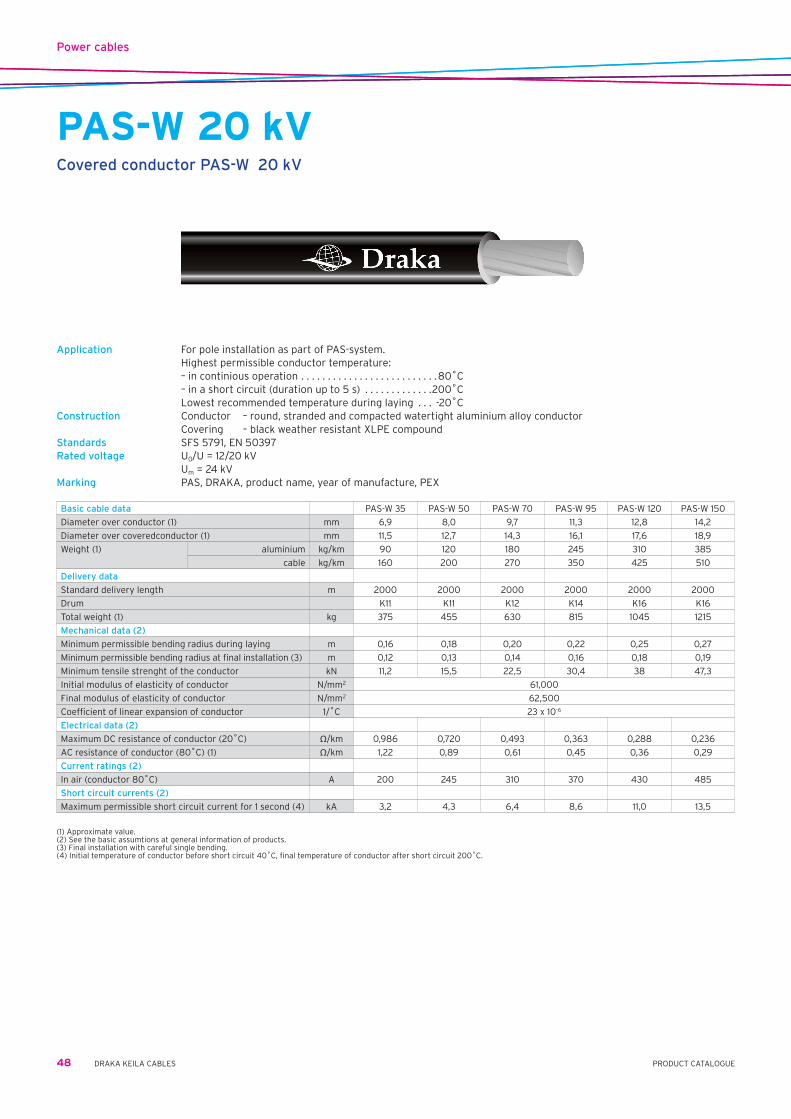
Power cables
48 DRAKA KEILA CABLES PRODUCT CATALOGUE
PAS-W 20 kVCovered conductor PAS-W 20 kV
Application For pole installation as part of PAS-system. Highest permissible conductor temperature: – in continious operation . . . . . . . . . . . . . . . . . . . . . . . . . .80˚C – in a short circuit (duration up to 5 s) . . . . . . . . . . . . .200˚C Lowest recommended temperature during laying . . . -20˚CConstruction Conductor – round, stranded and compacted watertight aluminium alloy conductor Covering – black weather resistant XLPE compoundStandards SFS 5791, EN 50397Rated voltage U0/U=12/20kV Um=24kVMarking PAS, DRAKA, product name, year of manufacture, PEX
Basic cable data PAS-W 35 PAS-W 50 PAS-W 70 PAS-W 95 PAS-W 120 PAS-W 150
Diameter over conductor (1) mm 6,9 8,0 9,7 11,3 12,8 14,2
Diameter over coveredconductor (1) mm 11,5 12,7 14,3 16,1 17,6 18,9
Weight (1) aluminium kg/km 90 120 180 245 310 385
cable kg/km 160 200 270 350 425 510
Delivery data
Standard delivery length m 2000 2000 2000 2000 2000 2000
Drum K11 K11 K12 K14 K16 K16
Total weight (1) kg 375 455 630 815 1045 1215
Mechanical data (2)
Minimum permissible bending radius during laying m 0,16 0,18 0,20 0,22 0,25 0,27
Minimum permissible bending radius at final installation (3) m 0,12 0,13 0,14 0,16 0,18 0,19
Minimum tensile strenght of the conductor kN 11,2 15,5 22,5 30,4 38 47,3
Initial modulus of elasticity of conductor N/mm2 61,000
Final modulus of elasticity of conductor N/mm2 62,500
Coefficient of linear expansion of conductor 1/˚C 23 x 10-6
Electrical data (2)
Maximum DC resistance of conductor (20˚C) Ω/km 0,986 0,720 0,493 0,363 0,288 0,236
AC resistance of conductor (80˚C) (1) Ω/km 1,22 0,89 0,61 0,45 0,36 0,29
Current ratings (2)
In air (conductor 80˚C) A 200 245 310 370 430 485
Short circuit currents (2)
Maximum permissible short circuit current for 1 second (4) kA 3,2 4,3 6,4 8,6 11,0 13,5
(1) Approximate value.(2) See the basic assumtions at general information of products.(3) Final installation with careful single bending.(4) Initial temperature of conductor before short circuit 40˚C, final temperature of conductor after short circuit 200˚C.

Installation cables and wires
49PRODUCT CATALOGUEDRAKA KEILA CABLES
PL / ML / H07V-UPVC-insulated solid conductor
Application For fixed installation in a conduit, and for wiring in appliances, switchgear and controlgear with a maximum voltage of 1000 V (a.c.) or a maximum of 750 V (d.c.) to earth.
Highest permissible conductor temperature – in continious operation . . . . . . . . . . . . . . . . . . . . . . . . . . 70˚C – in a short circuit (max.5 s) . . . . . . . . . . . . . . . . . . . . . . 160˚C Lowest recommended handling temperature . . . . . . . –25˚CConstruction Conductor . . . . . . . . . . . annealed copper wire Insulation . . . . . . . . . . . PVC, core identification by colours Standards EVS 719:1996, SFS 5523, CENELEC HD 21 Certificate / approval EEI, FI, <HAR>Rated voltage U0/U=450/750VBending radius During installation min. . . . . . . . . . . . . . . . . . . . . . . . . . . . . . 8D In a final installation if bent only once min. . . . . . . . . . . . . 3DIdentification of cores PRU – brown, MU – black, SI – blue, KORO – yellow-green
Basic cable data
Cross-section of conductor and colour PL 1,5 MU PL 1,5 PRU PL 1,5 SI PL 1,5 KORO PL 2,5 MU PL 2,5 PRU
EAN code (SSTL code) 64 100+ 04 012 03-1 04 012 02-4 04 012 07-9 04 012 09-3 04 012 23-9 04 012 22-2
Nominal overall diameter mm 2,7 2,7 2,7 2,7 3,3 3,3
Total weight kg/km 20 20 20 20 31 31
Direct current resistance of conductor at 20˚C max. Ω/km 12,1 12,1 12,1 12,1 7,41 7,41
Standard delivery length, coil m 200 200 200 200 200 200
Basic cable data
Cross-section of conductor and colour PL 2,5 SI PL 2,5 KORO PL 4 MU PL 4 PRU PL 4 SI PL 4 KORO
EAN code (SSTL code) 64 100+ 04 012 27-7 04 012 29-1 04 012 43-7 04 012 42-0 04 012 47-5 04 012 49-9
Nominal overall diameter mm 3,3 3,3 3,9 3,9 3,9 3,9
Total weight kg/km 31 31 50 50 50 50
Direct current resistance of conductor at 20˚C max. Ω/km 7,41 7,41 4,61 4,61 4,61 4,61
Standard delivery length, coil m 200 200 200 200 200 200

Installation cables and wires
50 DRAKA KEILA CABLES PRODUCT CATALOGUE
PK / MK / H07V-RPVC-insulated stranded conductor
Application For permanent installation in a conduit, and for wiring in appliances, switchgear and controlgear with a maximum voltage of 1000 V (a. c.) or a maximum of 750 V (d.c.) to earth.
Highest permissible conductor temperature – in continious operation . . . . . . . . . . . . . . . . . . . . . . . . . . 70˚C – in a short circuit (max. 5 s) . . . . . . . . . . . . . . . . . . . . . . 160˚C Lowest recommended handling temperature . . . . . . . -25˚CConstruction Conductor – annealed copper wires, stranded Insulation – PVC, core identification by coloursStandards EVS 718:1996, SFS 3103, CENELEC HD 21 Certificate / approval EEI, FI, <HAR>Rated voltage U0/U=450/750VBending radius During installation min. . . . . . . . . . . . . . . . . . . . . . . . . . . . . . 8D In a final installation if bent only once min. . . . . . . . . . . . . 3DIdentification of cores RU, PRU – brown, MU – black, KEVI, KORO – yellow-green, SI – blue
Cross-section of conductor and colour MK 1,5 RU MK 1,5 MU MK 1,5 SI MK 1,5 KEVI MK 2,5 RU MK 2,5 MU MK 2,5 SI
EAN code (SSTL code) 64 100+ 04 021 02-6 04 021 03-3 04 021 07-1 04 021 08-8 04 021 22-4 04 021 23-1 04 021 27-9
Nominal overall diameter mm 3 3 3 3 3,7 3,7 3,7
Total weight kg/km 22 22 22 22 35 35 35
Direct current resistance of conductor at 20˚C max. Ω/km 12,1 12,1 12,1 12,1 7,41 7,41 7,41
Standard delivery length, coil m 250 250 250 250 200 200 200
Cross-section of conductor and colour MK 2,5 KEVI MK 4 MU MK 4 SI MK 4 KEVI PK 6 MU PK 6 SI PK 6 KORO
EAN code (SSTL code) 64 100+ 04 021 28-6 04 021 43-9 04 021 47-7 04 021 48-4 04 024 63-8 04 024 67-6 04 024 69-0
Nominal overall diameter mm 3,7 4,2 4,2 4,2 4,8 4,8 4,8
Total weight kg/km 35 52 52 52 70 70 70
Direct current resistance of conductor at 20˚C max. Ω/km 7,41 4,61 4,61 4,61 3,08 3,08 3,08
Standard delivery length, coil m 200 150 150 150 100 100 100
Cross-section of conductor and colour PK 10 MU PK 10 SI PK 10 KORO PK 16 MU PK 16 SI PK 16 KORO PK 25 MU
EAN code (SSTL code) 64 100+ 04 024 73-7 04 024 77-5 04 024 79-9 04 024 83-6 04 024 87-4 04 024 89-8 04 024 91-1
Nominal overall diameter mm 6,1 6,1 6,1 7,2 7,2 7,2 8,9
Total weight kg/km 115 115 115 175 175 175 270
Direct current resistance of conductor at 20˚C max. Ω/km 1,83 1,83 1,83 1,15 1,15 1,15 0,727
Standard delivery length, coil m 100 100 100 100 100 100 100
Cross-section of conductor and colour PK 25 SI PK 25 KORO MK 35 MU MK 35 SI MK 35 KEVI MK 50 MU MK 50 SI
EAN code (SSTL code) 64 100+ 04 024 96-3 04 024 98-0 04 522 22-6 04 522 23-3 04 522 27-1 04 522 33-2 04 522 37-0
Nominal overall diameter mm 8,9 8,9 10 10 10 11,7 11,7
Total weight kg/km 270 270 370 370 370 510 510
Direct current resistance of conductor at 20˚C max. Ω/km 0,727 0,727 0,524 0,524 0,524 0,387 0,387
Standard delivery length, coil m 100 100
Standard delivery length, drum m 500/6C 500/6C 500/6C 200/6C 200/6C
Cross-section of conductor and colour MK 50 KEVI MK 70 KEVI MK 95 KEVI 120 KEVI
EAN code (SSTL code) 64 100+ 04 522 38-7 04 022 48-6 04 022 58-0 04 022 66-5
Nominal overall diameter mm 11.7 13.4 16 18
Total weight kg/km 510 710 1000 1200
Direct current resistance of conductor at 20˚C max. Ω/km 0.387 0.268 0.193 0.153
Standard delivery length, coil m
Standard delivery length, drum m 200/6C 200/6C 500/8E/ *) 800/11G/ *)

Installation cables and wires
51PRODUCT CATALOGUEDRAKA KEILA CABLES
MK 90 / H07V2-RPVC-insulated stranded conductor
Application For permanent installation in a conduit, and for wiring in appliances, switchgear and controlgear with a maximum voltage of 1000 V (a.c.) or a maximum of 750 V (d. c.) to earth.
Highest permissible conductor temperature – in continious operation . . . . . . . . . . . . . . . . . . . . . . . . . .90˚C – in a short circuit (max.5 s) . . . . . . . . . . . . . . . . . . . . . . 160˚C Lowest recommended handling temperature . . . . . . . -25˚CConstruction Conductor – annealed copper wires, stranded Insulation – lead-free Linyl PVC, core identification by coloursStandards SFS 5523, CENELEC HD 21, IEC 60332-14 Certificate / approval FI, <HAR>Rated voltage U0/U=450/750VBending radius During installation min. . . . . . . . . . . . . . . . . . . . . . . . . . . . . . 8D In a final installation if bent only once min. . . . . . . . . . . . . 3DIdentification of cores RU, PRU – brown, MU – black, KEVI – yellow-green, SI – blue
Cross-section of conductor and colour MK 1,5 RU MK 1,5 MU MK 1,5 SI MK 1,5 KEVI MK 2,5 RU MK 2,5 MU MK 2,5 SI
EAN code (SSTL code) 64 100+ 04 01704-3 04 01703-6 04 01705-0 04 01702-9 04 01708-1 04 01707-4 04 01709-8
Nominal overall diameter mm 3 3 3 3 3,7 3,7 3,7
Total weight kg/km 22 22 22 22 35 35 35
Direct current resistance of conductor at 20˚C max. Ω/km 12,1 12,1 12,1 12,1 7,41 7,41 7,41
Standard delivery length, coil m 250 250 250 250 200 200 200
Cross-section of conductor and colour MK 2,5 KEVI MK 4 MU MK 4 SI MK 4 KEVI PK 6 RU PK 6 MU PK 6 SI
EAN code (SSTL code) 64 100+ 04 01706-7 04 01711-91 04 01713-5 04 01710-4 04 01716-6 04 01715-9 04 01717-3
Nominal overall diameter mm 3,7 4,2 4,2 4,2 4,8 4,8 4,8
Total weight kg/km 35 52 52 52 70 70 70
Direct current resistance of conductor at 20˚C max. Ω/km 7,41 4,61 4,61 4,61 3,08 3,08 3,08
Standard delivery length, coil m 200 150 150 150 100 100 100
Cross-section of conductor and colour PK 6 KEVI PK 10 MU PK 10 SI PK 10 KEVI PK 16 MU PK 16 SI PK 16 KEVI
EAN code (SSTL code) 64 100+ 04 01714-2 04 01719-5 04 01720-3 04 01718-0 04 01722-7 04 01723-4 04 01721-0
Nominal overall diameter mm 4,8 6,1 6,1 6,1 7,2 7,2 7,2
Total weight kg/km 70 115 115 115 175 175 175
Direct current resistance of conductor at 20˚C max. Ω/km 3,08 1,83 1,83 1,83 1,15 1,15 1,15
Standard delivery length, coil m 100 100 100 100 100 100 100
Cross-section of conductor and colour PK 25 SI PK 25 KEVI MK 35 MU MK 35 SI MK 35 KEVI MK 50 MU MK 50 SI
EAN code (SSTL code) 64 100+ 04 02215-3 04 02216-0 04 52222-6 04 52223-3 04 52227-1 04 52233-2 04 52237-0
Nominal overall diameter mm 8,9 8,9 10 10 10 11,7 11,7
Total weight kg/km 270 270 370 370 370 510 510
Direct current resistance of conductor at 20˚C max. Ω/km 0,727 0,727 0,524 0,524 0,524 0,387 0,387
Standard delivery length, coil m 100 100
Standard delivery length, drum m 500/6C 500/6C 500/6C 200/6C 200/6C
Cross-section of conductor and colour MK 50 KEVI MK 70 KEVI MK 95 KEVI 120 KEVI
EAN code (SSTL code) 64 100+ 04 52238-7 04 022 48-6 04 022 58-0 04 022 66-5
Nominal overall diameter mm 11,7 13,4 16 18
Total weight kg/km 510 710 1000 1200
Direct current resistance of conductor at 20˚C max. Ω/km 0,387 0,268 0,193 0,153
Standard delivery length, drum m 200/6C 200/6C 500/8E/ *) 800/11G/ *)

Installation cables and wires
52 DRAKA KEILA CABLES PRODUCT CATALOGUE
MKEM 90 / H07V2-KPVC-insulated flexible conductor
Application For fifed installation in a conduit, and for wiring in appliances, switchgear and controlgear with a maximum voltage of 1000 V (a.c.) or a maximum of 750 V (d.c.) to earth.
Highest permissible conductor temperature – in continious operation . . . . . . . . . . . . . . . . . . . . . . . . . .90˚C – in a short circuit (max.5 s) . . . . . . . . . . . . . . . . . . . . . . 160˚C Lowest recommended handling temperature . . . . . . . -25˚CConstruction Conductor – annealed copper wires, stranded flexible Insulation – lead-free Linyl PVC, core identification by coloursStandards SFS 5523, CENELEC HD 21, IEC 60332-14 Certificate / approval FI, <HAR>Rated voltage U0/U=450/750VBending radius During installation min. . . . . . . . . . . . . . . . . . . . . . . . . . . . . . 8D In a final installation if bent only once min. . . . . . . . . . . . . 3DIdentification of cores RU – brown, MU – black, KEVI – yellow-green, SI – blue
Cross-section of conductor and colour 1,5 RU 1,5 MU 1,5 SI 1,5 KEVI 2,5 RU 2,5 MU 2,5 SIEAN code (SSTL code) 64 100+ 04 03102-5 04 03103-2 04 03107-0 04 03108-7 04 03122-3 04 03123-0 04 03127-8Nominal overall diameter mm 3 3 3 3 3,6 3,6 3,6Total weight kg/km 21 21 21 21 32 32 32Direct current resistance of conductor at 20˚C max. Ω/km 13,3 13,3 13,3 13,3 7,98 7,98 7,98Standard delivery length, coil m 250 250 250 250 200 200 200
Cross-section of conductor and colour 64 100+ 2,5 KEVI 4 MU 4 SI 4 KEVI 6 MU 6 SI 6 KEVIEAN code (SSTL code) 04 03128-5 04 03143-8 04 03147-6 04 03148-3 04 03163-6 04 03167-4 04 03168-1Nominal overall diameter mm 3,6 4,1 4,1 4,1 5,0 5,0 5,0Total weight kg/km 32 45 45 45 70 70 70Direct current resistance of conductor at 20˚C max. Ω/km 7,98 4,95 4,95 4,95 3,30 3,30 3,30Standard delivery length, coil m 200 100 100 100 100 100 100
Cross-section of conductor and colour 10 MU 10 SI 10 KEVI 16 MU 16 SI 16 KEVI 25 MUEAN code (SSTL code) 64 100+ 04 03183-4 04 03187-2 04 03188-9 04 03203-9 04 03207-9 04 03208-9 04 03213-8Nominal overall diameter mm 6,5 6,5 6,5 7,6 7,6 7,6 9,4Total weight kg/km 115 115 115 170 170 170 270Direct current resistance of conductor at 20˚C max. Ω/km 1,91 1,91 1,91 1,21 1,21 1,21 0,780Standard delivery length, coil m 100 100 100 100 100 100 100
Cross-section of conductor and colour 25 SI 25 KEVI 35 MU 35 SI 35 KEVI 50 MU 50 SIEAN code (SSTL code) 64 100+ 04 03217-6 04 03218-3 04 53223-2 04 53227-0 04 53228-7 04 53233-1 04 53237-9Nominal overall diameter mm 9,4 9,4 11,0 11,0 11,0 13,0 13,0Total weight kg/km 270 270 370 370 370 520 520Direct current resistance of conductor at 20˚C max. Ω/km 0,780 0,780 0,554 0,554 0,554 0,386 0,386Standard delivery length, coil m 100 100Standard delivery length, drum m 500/6C 500/6C 500/6C 200/6C 200/6C
Cross-section of conductor and colour 50 KEVI 70 MU 70 SI 70 KEVI 95 MU 95 SI 120 MUEAN code (SSTL code) 64 100+ 04 53238-6 04 022 43-0 04 022 47-8 04 022 48-5 04 03253-4 04 03257-2 04 032 63-3Nominal overall diameter mm 13,0 15,0 15,0 15,0 17,5 17,5 19,0Total weight kg/km 520 730 730 730 940 940 1200Direct current resistance of conductor at 20˚C max. Ω/km 0,386 0,272 0,272 0,272 0,206 0,206 0,161Standard delivery length, drum m 200/6C 200/6C 200/6C 200/6C 200/7E 200/7E 200/7E
Cross-section of conductor and colour 150 MUEAN code (SSTL code) 64 100+ 04 032 73-2Nominal overall diameter mm 22,0Total weight kg/km 1450Direct current resistance of conductor at 20˚C max. Ω/km 0,129Standard delivery length, drum m 200/7E

Installation cables and wires
53PRODUCT CATALOGUEDRAKA KEILA CABLES
PPO / MMOPVC sheated control cable
Application Cables for control, measuring and signal circuits of electrical equipment. Fixed surface or flush-mounted installations, indoors and outdoors. Direct sunlight may change the colour of the sheath. Highest permissible conductor temperature – in continious operation . . . . . . . . . . . . . . . . . . . . . . . . . . 70˚C – in a short circuit (max. 5 s) . . . . . . . . . . . . . . . . . . . . . . 160˚C Lowest recommended handling temperature . . . . . . . .–15˚CConstruction Conductor – annealed copper wires Insulation – black PVC, core identification by numbers Sheath – white PVC, marked by metersStandards EVS 722:1996, SFS 3714; HD 627Certificate / approval EEI, FIRated voltage U0/U=450/750VBending radius During installation min. . . . . . . . . . . . . . . . . . . . . . . . . . . . . 10D In a final installation if bent only once min. . . . . . . . . . . . . 3DIdentification of cores Core identification by numbers
Number of conductors and cross-section n x mm2 7x1,5 12x1,5 19x1,5 27x1,5 37x1,5
EAN code (SSTL-code) 64 100+ 04 112 03-8 04 112 05-2 04 112 07-6 04 120 25-5 04 120 26-2
Nominal overall diameter mm 12 15 18 21 24
Total weight kg/km 230 350 500 700 950
Direct current resistance of conductor at 20˚C max. Ω/km 12,1 12,1 12,1 12,1 12,1
Standard delivery length, drum m 1000/K8 500/K8 500/K9 500/K11 500/K11
Number of conductors and cross-section n x mm2 7x2,5 12x2,5 19x2,5
EAN code (SSTL-code) 64 100+ 04 112 13-7 04 112 15-1 04 112 17-5
Nominal overall diameter mm 14 18 21
Total weight kg/km 310 500 750
Direct current resistance of conductor at 20˚C max. Ω/km 7,41 7,41 7,41
Standard delivery length, drum m 500/K8 500/K8 500/K11
Nominal values unless otherwise specified.

Installation cables and wires
54 DRAKA KEILA CABLES PRODUCT CATALOGUE
EKLK 450/750 VInstallation cable
Application fields Fixed installation, indoors and outdoors, in pipes, ducts, in or under plaster, also suspended in catenary system. In ground, only if the cable is protected against mechanical damage.
Alternative designation SE-N07VA5EV-UStandard SS 424 02 19-4Fire propagation class F3 acc. to SS 424 14 75 and IEC 60332-1 and SS-EN 50265-2-1Temperature range In continuous operation max. conductor temp 70 ºC. Lowest cable temperature under installation: -15 ºC and below 0 ºC special precaution shall be taken.Approval SEMKO, CEMaterial declaration EKLKHalogen free alternative EQLQBending radius 12D (6D in final installation, bent only once)Design Conductor . . . . . . . . . . . . .solid and annealed copper acc. to IEC 60228 class 1 Insulation . . . . . . . . . . . . .lead free PVC Core identification . . . . . .2-core: blue, brown 3-core: green/yellow, blue, brown 4-core: green/yellow, blue, brown, black 5-core: green/yellow, blue, brown, black, grey Filler . . . . . . . . . . . . . . . . . .lead free PVC Concentric conductor . . .aluminium with bonded PVC in contact with drain wire of tinned copper Inner sheath . . . . . . . . . . .PE, white Sheath . . . . . . . . . . . . . . . .lead free PVC, white, metre-marked Marking e.g. . . . . . . . . . . .EKLK 3G1,5 S BLYFRI F3 DRAKA SE
Without earth conductor With earth conductor
Number of cores x cross-section of conductor mm2 2x1,5 2x1,5 3G1,5 3G1,5 3G1,5 3G1,5 3G2,5 3G2,5
Overall diameter (approx.) mm 10 10 9,8 9,8 9,8 9,8 11,6 11,6
Weight (approx.) kg/100 m 14,3 14,3 14,0 14,0 14,0 14,0 21,3 21,3
Standard delivery length m 50 500 50 250 500 1000 50 150
Standard drum size/Package Ring K6 Ring K4 K6 K7 Ring K4
Articlenumber 423101 423105 423001 423003 423005 423006 423011 423013
With earth conductor
Number of cores x cross-section of conductor mm2 3G2,5 3G2,5 4G1,5 4G1,5 4G1,5 4G2,5 4G2,5 5G1,5
Overall diameter (approx.) mm 11,6 11,6 10,8 10,8 10,8 13,1 13,1 11,8
Weight (approx.) kg/100 m 21,3 21,3 19,0 19,0 19,0 25,7 25,7 22,5
Standard delivery length m 500 1000 50 200 500 50 500 50
Standard drum size/Package K6 K8 Ring K4 K6 Ring K7 Ring
Articlenumber 423015 423016 423021 423023 423025 423031 423035 423041
With earth conductor
Number of cores x cross-section of conductor mm2 5G1,5 5G1,5 5G1,5 5G2,5 5G2,5 5G2,5 5G2,5
Overall diameter (approx.) mm 11,8 11,8 11,8 13,9 13,9 13,9 13,9
Weight (approx.) kg/100 m 22,5 22,5 22,5 30,9 30,9 30,9 30,9
Standard delivery length m 150 500 1000 50 150 500 1000
Standard drum size/Package K4 K7 K9 Ring K4 K7 K9
Articlenumber 423043 423045 423046 423051 423053 423055 423056

Installation cables and wires
55PRODUCT CATALOGUEDRAKA KEILA CABLES
PPJPVC sheathed installation cable
Application For fixed surface or flush-mounted installations, indoors and outdoors. Suitable for installation in a slot covered with plaster. Not for installation directly in ground for directly in concrete without protective ducting. Not for installations subject to electrical interference (see MCCMK and MJAM). Direct sunlight may change colour of sheath. Current carrying capacities according to HD 384.5.523 (or IEC 364-5-523): “Electrical installation of buildings” section 523: Current carrying capacities.
Highest permissible conductor temperature – in continious operation . . . . . . . . . . . . . . . . . . . . . . . . . . . . . . . 70˚C – in a short circuit (max. 5 s) . . . . . . . . . . . . . . . . . . . . . . . . . . . 160˚C Lowest recommended handling temperature . . . . . . . . . . . . .–15˚C Max. permissible tensile stress during installation . . Ax50 N/mm2
Bending radius Recommended during installation min . . . . . . . . . . . . . . . . . . . . 10D In a final installation if bent only once min . . . . . . . . . . . . . . . . . . 3DConstruction Conductor . . . . . . . . . . . annealed copper wires. (1,5 – 4 mm2) solid (6 – 25 mm2) stranded Insulation . . . . . . . . . . . PVC, core identification by colours Filling . . . . . . . . . . . . . . . filling compound Sheath . . . . . . . . . . . . . . white PVC, marked by metersIdentification of cores Core identification according to the HD 308 S2:2001 standard X type without green/yellow core – 2-core . . . . . . . . . . . . . . . . . . blue, brown 3-core . . . . . . . . . . . . . . . . . . brown, black, grey G type with green/yellow core – 3-core . . . . . . . . . . . . . . . . . . green/yellow, blue, brown 4-core (1,5 ja 2,5 mm2) . . . . green/yellow, blue, brown,black 4-core (4 – 25 mm2) . . . . . . green/yellow, brown, black, grey 5-core . . . . . . . . . . . . . . . . . . green/yellow, blue, brown, black, greyStandards EVS 720:1996, EVS 721:1996, SFS 2091, SFS 5524 Certificate / approval EEI, FI, CERated voltage U0/U=300/500V(1,5–4mm2) U0/U=450/750V(6–25mm2)

Installation cables and wires
56 DRAKA KEILA CABLES PRODUCT CATALOGUE
With protective conductor
Number of conductors and cross-section 3G1,5 4G1,5 5G1,5 3G2,5 4G2,5 5G2,5
EAN code (SSTL-code) reel 64 100+ 04 072 22-6 04 072 32-5 04 072 42-4 04 072 23-3 04 072 33-2 04 072 43-1
EAN code (SSTL-code) drum 64 100+ 04 572 22-1 04 572 32-0 04 072 42-9 04 572 23-8 04 572 33-7 04 572 43-6
Nominal overall diameter mm 9 10 10 10 11 12
Total weight kg/km 125 155 180 180 220 260
Direct current resistance of conductor at 20˚C max. Ω/km 12,1 12,1 12,1 7,41 7,41 7,41
Standard delivery length reel m 100 100 50 100 50 50
drum m 2000 1000 1000 1000 1000 750
PPJPVC sheathed installation cable
Without protective conductor
Number of conductors and cross-section n x mm2 2x1,5 3x1,5 2x2,5
EAN code (SSTL-code) reel 64 100+ 04 073 12-4 04 073 22-3 04 073 13-1
Nominal overall diameter mm 8 9 10
Total weight kg/km 105 125 150
Direct current resistance of conductor at 20˚C max. Ω/km 12,1 12,1 7,41
Standard delivery length, reel m 100 100 100
With protective conductor
Number of conductors and cross-section 3G4 4G4 5G4 3G6 4G6 5G6
EAN code (SSTL-code) 64 100+ 04 572 24-5 04 572 34-4 04 572 44-3 04 572 25-2 04 572 35-1 04 572 45-0
Nominal overall diameter mm 10 12 13 14 16 17
Total weight kg/km 280 340 410 350 430 510
Direct current resistance of conductor at 20˚C max. Ω/km 4,61 4,61 4,61 3,08 3,08 3,08
Standard delivery length, drum m 1000 750 500 500 500 500
With protective conductor
Number of conductors and cross-section 4G10 5G10 4G16 5G16 4G25 5G25
EAN code (SSTL-code) 64 100+ 04 572 36-8 04 572 46-7 04 572 37-5 04 572 47-4 04 572 38-2 04 572 48-1
Nominal overall diameter mm 19 21 22 24 30 31
Total weight kg/km 670 810 950 1150 1780 1900
Direct current resistance of conductor at 20˚C max. Ω/km 1,83 1,83 1,15 1,15 0,727 0,727
Standard delivery length, drum m 400 250 250 250 250 250

Installation cables and wires
57PRODUCT CATALOGUEDRAKA KEILA CABLES
MSK / H05VV-FFlexible cord
Application Cord for ordinary duty use for portable appliences in domestic premises, kitchens and offices. - For household appliences in dry and damp premises. - Not for outdoor use, industrial use, agricultural use The weight of a lighting fixture hanging from the cable must not exceed 2 kg. Maximum permissible temperature of conductor: – in continuous use . . . . . . . . . . . . . . . . . . . . . . . . . . . . . . . . . .+60˚C - in a short circuit (max. 5 s) . . . . . . . . . . . . . . . . . . . . . . . . . +150˚C Lowest recommended handling temperature . . . . . . . . . . . . +5˚C Minimum recommended bending radius in normal usage . . . . 6DConstruction Conductor . . . . . . . . . . . Annealed copper wires, stranded, flexible Insulation . . . . . . . . . . . PVC, core identification by colours Sheath . . . . . . . . . . . . . . PVC, roundCore identification N type without green/yellow core 2-core S type with green/yellow core . . . BU- BN 3-core . . . . . . . . . . . . . . . . . . . . . . . GNYE – BU – BN 4-core . . . . . . . . . . . . . . . . . . . . . . . GNYE – BK – BU – BN 5-core . . . . . . . . . . . . . . . . . . . . . . . GNYE – BK – BU – BN – BKStandard SFS5525=CENELECHD21Sertificate/approval FI (FIMKO), CE, <HAR>Rated voltage U0/U=300/500V
WITH PROTECTIVE CONDUCTOR
Number of conductors and cross-section 3 x 0,75 S 3 x 1,0 S 3 x 1,5 S white 3 x 1,5 S grey
EAN code (SSTL-code) 64 100+ 04 197 20-2 04 197 21-9 04 197 22-6 04 198 22-3
Nominal overall diameter mm 6,6 7,0 8,3 8,3
Total weight kg/km 65 72 100 100
Direct current resistance of conductor at +20˚C max. ohm/km 26,0 19,5 13,3 13,3
Standard delivery length coil m 100 100 100 100
ABBREVIATIONS OF COLOURSVA=WHWhiteHA=GYGrey
WITH PROTECTIVE CONDUCTOR
Number of conductors and cross-section 4 x 0,75 S 4 x 1,5 S 5 x 1,0 S 5 x 1,5 S
EAN code (SSTL-code) 64 100+ 04 197 30-1 04 197 32-5 04 197 41-7 04 197 42-4
Nominal overall diameter mm 7,2 9,3 8,6 10,3
Total weight kg/km 75 130 110 160
Direct current resistance of conductor at +20˚C max. ohm/km 26,0 13,3 19,5 13,3
Standard delivery length coil m 100 100 100 100
WITHOUT PROTECTIVE CONDUCTOR
Number of conductors and cross-section 2 x 0,75 N 2 x 1,0 N 2 x 1,5 N
EAN code (SSTL-code) 64 100+ 04 194 10-2 04 194 11-9 04 194 12-6
Nominal overall diameter mm 6,2 6,6 7,6
Total weight kg/km 52 60 80
Direct current resistance of conductor at +20˚C max. ohm/km 26,0 19,5 13,3
Standard delivery length coil m 100 100 100

Installation cables and wires
58 DRAKA KEILA CABLES PRODUCT CATALOGUE
MSO / H03VVH2-FFlexible cord
Application Cord for light duty use for portable appliences in domestic premises, kitchens and offices. - Not for kitchen or heating appliances - Not for outdoor use, industrial use, agricultural use or for non domestic portable tools The weight of the lighting fixture hanging from the cable must not exceed 2 kg. Maximum permissible temperature of conductor: - in continuous use . . . . . . . . . . . . . . . . . . . . . . . . . . . . . .+60˚C - in a short circuit (max. 5 s) . . . . . . . . . . . . . . . . . . . . . +150˚C Lowest recommended handling temperature . . . . . . . . +5˚C Minimum recommended bending radius: - in normal usage . . . . . 6DConstruction Conductor . . . . . . . . . . . annealed copper wires, stranded, flexible Insulation . . . . . . . . . . . PVC, core identification by colours Sheath . . . . . . . . . . . . . . PVC covering two insulated and parallel conductors, flatCore identification N type without green/yellow core 2-core BU – BNStandard SFS5525=CENELECHD21Sertificate/approval FI (FIMKO), CE, <HAR>Rated voltage U0/U=300/300V
WITHOUT PROTECTIVE CONDUCTOR
Number and cross-section of conductors and sheath colour nxmm2 2 x 0,75 N VA 2 x 0,75 N HA 2 x 0,75 N RU 2 x 0,75 N MU
EAN code (SSTL-code) 64 100+ 04 181 20-1 04 181 21-8 04 181 22-5 04 181 23-2
Nominal overall diameter mm 3,3 x 5,5 3,3 x 5,5 3,3 x 5,5 3,3 x 5,5
Total weight kg/km 31 31 31 31
Direct current resistance of conductor at +20˚C max. ohm/km 26,0 26,0 26,0 26,0
Standard delivery length spool (P2) m 200 200 200 200
ABBREVIATIONS OF COLOURSMU=BKBlackRU=BNBrownVA=WHWhiteHA=GYGrey

Installation cables and wires
59PRODUCT CATALOGUEDRAKA KEILA CABLES
MSOY / H03VV-FPVC sheathed flexible installation cable
Application Cord for light duty use for portable appliances in domestic premises and offices. Not for outdoor use, industrial use, agricultural use. The weight of the lighting fixture hanging from the cable must no exceed 2 kg. Highest permissible conductor temperature – in continious operation . . . . . . . . . . . . . . . . . . . . . . . . . .60˚C – in a short circuit (max. 5 s) . . . . . . . . . . . . . . . . . . . . . 150˚C Lowest recommended handling temperature . . . . . . . . . 5˚C Minimum recommended bendung radius - during installation . . . 6DConstruction Conductor . . . . . . . . . . . annealed flexible copper wires. Insulation . . . . . . . . . . . PVC, core identification by colours Sheath . . . . . . . . . . . . . . PVC MU – black VA – whiteIdentification of cores Colours . . . . . . . . . . . . . blue, brownStandards SFS5525=CENELECHD21Certificate / approval EEI, FI, CE, <HAR>Rated voltage U0/U=300/300V
Without protective earth core
Number of conductors and cross-section n x mm2 2 x 0,75 N VA 2 x 0,75 N MU
EAN code (SSTL-code) 64 100+ 04 181 70-6 04 181 73-7
Nominal overall diameter mm 5,4 5,4
Total weight kg/km 41 41
Direct current resistance of conductor at 20˚C max. Ω/km 26 26
Standard delivery length m 100 100
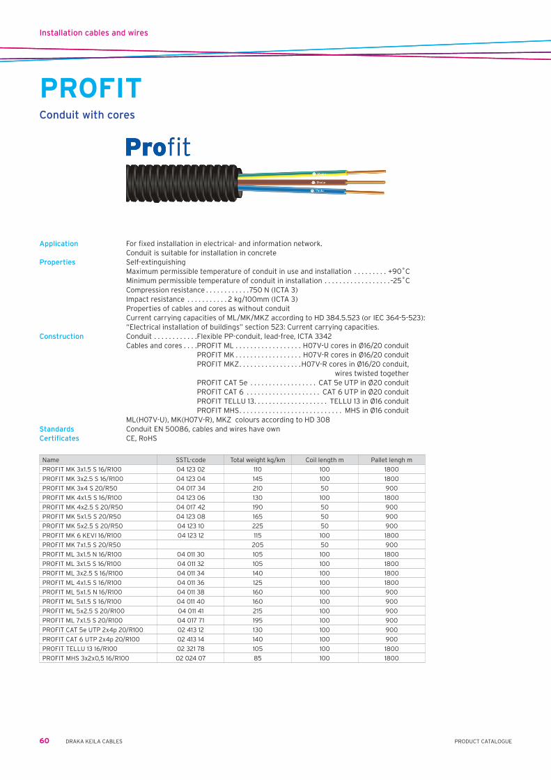
Installation cables and wires
60 DRAKA KEILA CABLES PRODUCT CATALOGUE
PROFITConduit with cores
Application For fixed installation in electrical- and information network. Conduit is suitable for installation in concreteProperties Self-extinguishing Maximum permissible temperature of conduit in use and installation . . . . . . . . . +90˚C Minimum permissible temperature of conduit in installation . . . . . . . . . . . . . . . . . . –25˚C Compression resistance . . . . . . . . . . . .750 N (ICTA 3) Impact resistance . . . . . . . . . . . 2 kg/100mm (ICTA 3) Properties of cables and cores as without conduit Current carrying capacities of ML/MK/MKZ according to HD 384.5.523 (or IEC 364-5-523):
“Electrical installation of buildings” section 523: Current carrying capacities.Construction Conduit . . . . . . . . . . . .Flexible PP-conduit, lead-free, ICTA 3342 Cables and cores . . . .PROFIT ML . . . . . . . . . . . . . . . . . . H07V-U cores in Ø16/20 conduit PROFIT MK . . . . . . . . . . . . . . . . . . H07V-R cores in Ø16/20 conduit PROFIT MKZ . . . . . . . . . . . . . . . . .H07V-R cores in Ø16/20 conduit, wires twisted together PROFIT CAT 5e . . . . . . . . . . . . . . . . . . CAT 5e UTP in Ø20 conduit PROFIT CAT 6 . . . . . . . . . . . . . . . . . . . . CAT 6 UTP in Ø20 conduit PROFIT TELLU 13 . . . . . . . . . . . . . . . . . . . . TELLU 13 in Ø16 conduit PROFIT MHS . . . . . . . . . . . . . . . . . . . . . . . . . . . . MHS in Ø16 conduit ML(H07V-U), MK(H07V-R), MKZ colours according to HD 308Standards Conduit EN 50086, cables and wires have ownCertificates CE, RoHS
Name SSTL-code Total weight kg/km Coil length m Pallet lengh m
PROFIT MK 3x1.5 S 16/R100 04 123 02 110 100 1800
PROFIT MK 3x2.5 S 16/R100 04 123 04 145 100 1800
PROFIT MK 3x4 S 20/R50 04 017 34 210 50 900
PROFIT MK 4x1.5 S 16/R100 04 123 06 130 100 1800
PROFIT MK 4x2.5 S 20/R50 04 017 42 190 50 900
PROFIT MK 5x1.5 S 20/R50 04 123 08 165 50 900
PROFIT MK 5x2.5 S 20/R50 04 123 10 225 50 900
PROFIT MK 6 KEVI 16/R100 04 123 12 115 100 1800
PROFIT MK 7x1.5 S 20/R50 205 50 900
PROFIT ML 3x1.5 N 16/R100 04 011 30 105 100 1800
PROFIT ML 3x1.5 S 16/R100 04 011 32 105 100 1800
PROFIT ML 3x2.5 S 16/R100 04 011 34 140 100 1800
PROFIT ML 4x1.5 S 16/R100 04 011 36 125 100 1800
PROFIT ML 5x1.5 N 16/R100 04 011 38 160 100 900
PROFIT ML 5x1.5 S 16/R100 04 011 40 160 100 900
PROFIT ML 5x2.5 S 20/R100 04 011 41 215 100 900
PROFIT ML 7x1.5 S 20/R100 04 017 71 195 100 900
PROFIT CAT 5e UTP 2x4p 20/R100 02 413 12 130 100 900
PROFIT CAT 6 UTP 2x4p 20/R100 02 413 14 140 100 900
PROFIT TELLU 13 16/R100 02 321 78 105 100 1800
PROFIT MHS 3x2x0,5 16/R100 02 024 07 85 100 1800

Automation, data and telecommunication cables
61PRODUCT CATALOGUEDRAKA KEILA CABLES
JAMAKInstrumentation cable
Applications •Fixedindoorinstallations •Automation •Instrumentation •Processcontrol •Audiosystems •SuitableforMaxiTermipointconnectionsConstruction Conductor . . . . . . . . . . . stranded tinned copper Insulation . . . . . . . . . . . PE Unit . . . . . . . . . . . . . . . . twisted and individually with, plastic-aluminium tape shielded pair,
earth conductor and a number tape Shield . . . . . . . . . . . . . . . plastic-aluminium tape with earth conductor Sheath . . . . . . . . . . . . . . grey Linyl-PVCIdentification Units marked with numbers, a-conductors are blue and b-conductors are red.
Dimensions
Number and size of the conductor mm2 2 x(2+1)x 0,5 4 x(2+1)x 0,5 8 x(2+1)x 0,5 12 x(2+1)x 0,5 24 x(2+1)x 0,5 48 x(2+1)x 0,5
EAN code (SSTL code) 64 100+ 02 642 52-0 02 642 54-4 02 642 58-2 02 642 62-9 02 642 64-3 02 642 68-1
Nominal diameter mm 8 9,5 13 15 21 29
Mass kg/km 70 110 200 280 530 990
Delivery length m 1000 1000 1000 1000 1000 500
Drum K6 K7 K9 K10 K12 K12
Electrical properties 20˚C
Maximum loop resistance Ω/km 81
Nominal mutual capacitance (800 Hz) nF/km 85
Impedance, 10 MHz Ω 70 ± 10 %
Minimum insulation resistance GΩ x km 2
Velocity factor 0,66
Maximum voltage V 75
Nominal attenuation frequency 9,6 kHz dB/100 m 0,3
frequency 19,2 kHz dB/100 m 0,5
frequency 64 kHz dB/100 m 0,7
frequency 100 kHz dB/100 m 0,9
frequency 200 kHz dB/100 m 1,6
frequency 1,0 MHz dB/100 m 4,5
Other properties
Bending radius during installation, min. mm 15D
(D=outerdiameter) during operation, min. mm 10D
Installation temperature min. ˚C –5
Max operation temperature ˚C 70

Automation, data and telecommunication cables
62 DRAKA KEILA CABLES PRODUCT CATALOGUE
JAMAK ARMInstrumentation cable
Applications •Fixedoutdoorinstallations •Automation •Instrumentation •Processcontrol •Audiosystems •SuitableforMaxiTermipointconnections Suitable specially for digital and low level analog signal transmission. The construction gives an excellent protection against electromagnetic interference. Construction Conductor . . . . . . . . . . . stranded tinned copper Insulation . . . . . . . . . . . PE Unit . . . . . . . . . . . . . . . . twisted and individually with plastic-aluminium tape shielded pair,
earth conductor and a number tape Shield . . . . . . . . . . . . . . . plastic/aluminium tape with earth conductor Sheath . . . . . . . . . . . . . grey Linyl-PVC Armouring . . . . . . . . . . wrapped steel band Outersheath . . . . . . . . black PEIdentification Units marked with number tape, a-conductors are blue and b-conductors are red Other properties JAMAK ARM is also available as halogenfree (JAMAK ARM-HF)
Dimensions
Number and size of the conductor mm2 4 x (2+1) x 0,5 8 x (2+1) x 0,5 12 x (2+1) x 0,5 24 x (2+1) x 0,5 48 x (2+1) x 0,5
EAN code (SSTL code) 64 100+ 02 642 72-4 02 642 78-0 02 642 82-7 02 642 84-1 02 642 88-9
Nominal diameter mm 14 17 19 25 33
Mass kg/km 240 370 480 820 1440
Delivery length m 1000 1000 1000 1000 500
Drum K9 K11 K11 K14 K18
Electrical properties 20˚C
Maximum loop resistance Ω/km 81
Nominal mutual capacitance (800 Hz) nF/km 85
Impedance, 10 MHz Ω 70 ± 10 %
Minimum insulation resistance GΩ x km 2
Velocity factor 0,66
Maximum voltage V 75
Nominal attenuation frequency 9,6 kHz dB/100 m 0,3
frequency 19,2 kHz dB/100 m 0,5
frequency 64 kHz dB/100 m 0,7
frequency 100 kHz dB/100 m 0,9
frequency 200 kHz dB/100 m 1,6
frequency 1,0 MHz dB/100 m 4,5
Other properties
Bendingradius(D=outerdiameter) during installation, min. mm 15D
during operation, min. mm 10 D
Installation temperature min. ˚C -5
Max operation temperature ˚C 70

Automation, data and telecommunication cables
63PRODUCT CATALOGUEDRAKA KEILA CABLES
NOMAK Instrumentation cable
Application •Fixedindoorinstallations •Automation •Instrumentation •Processcontrol •SuitableforMaxiTermipointconnectionsConstruction Conductor . . . . . . . . . . . stranded tinned copper Insulation . . . . . . . . . . . PVC Unit . . . . . . . . . . . . . . . . twisted pair Overall shield . . . . . . . . plastic/aluminium tape with earth conductor Sheath . . . . . . . . . . . . . . grey Linyl-PVCIdentification Pairs marked with numbers, a-conductors are orange and b-conductors are white.
Dimensions
Number and size of the conductor n x n mm2 2 x 2 x 0,5 4 x 2 x 0,5 8 x 2 x 0,5 12 x 2 x 0,5 24 x 2 x 0,5 48 x 2 x 0,5
EAN code (SSTL code) 64 100+ 02 649 52-9 02 649 54-3 02 649 58-1 02 649 62-8 02 649 64-2 02 649 68-0
Nominal diameter mm 7,5 9 12 13 18 24
Mass kg/km 55 85 150 210 400 720
Delivery length m 1000 1000 1000 1000 1000 1000
Drum K6 K6 K7 K9 K11 K14
Electrical properties 20˚C
Maximum loop resistance Ω/km 81 81 81 81 81 81
Nominal mutual capacitance (800 Hz) nF/km 90 90 85 85 85 85
Impedance, 10 MHz Ω 100 ± 10 %
Minimum insulation resistance GΩ x km 100
Velocity factor 0,6
Maximum voltage V 75
Nominal attenuation frequency 9,6 kHz dB/100 m 0,3
frequency 19,2 kHz dB/100 m 0,5
frequency 64 kHz dB/100 m 0,7
frequency 100 kHz dB/100 m 0,9
frequency 200 kHz dB/100 m 1,5
frequency 1,0 MHz dB/100 m 2,9
Other properties
Bending radius during installation, min. mm 15D
(D – outer diameter) during operation, min. mm 10D
Installation temperature min. ˚C -5
Max operation temperature ˚C 70

Automation, data and telecommunication cables
64 DRAKA KEILA CABLES PRODUCT CATALOGUE
KLMSignal cable
Applications •Fixedindoorinstallations •Buildingautomation •Alarm,signalandsecuritycontroltransmissionConstruction According to . . . . . . . . . SFS 2751 Conductor . . . . . . . . . . . tinned copper Insulation . . . . . . . . . . . PVC Unit . . . . . . . . . . . . . . . . insulated conductors twisted together Sheath . . . . . . . . . . . . . . Grey Linyl-PVCIdentification 1. conductor . . . . . . . . . blue 2. conductor . . . . . . . . . yellow 3. conductor . . . . . . . . . white 4. conductor . . . . . . . . . redOther properties KLM is also available as halogenfree KLM-LSZH version
Dimensions
Number and size of the conductor n x mm 2 x 0,8 4 x 0,8
EAN code (SSTL code) 64 100+ 02 910 01-8 02 910 03-2
Nominal diameter mm 4,5 5
Mass kg/km 25 40
Delivery length m 500 500
Electrical properties 20˚C
Maximum loop resistance Ω/km 36,7 36,7
Minimum insulation resistance GΩ x km 500 500
Maximum voltage V 75 75
Other properties
Bending radius during installation, min. mm 15D 15D
(D=outerdiameter) during operation, min. mm 10D 10D
Installation temperature min. ˚C –5 –5
Max operation temperature ˚C 70 70
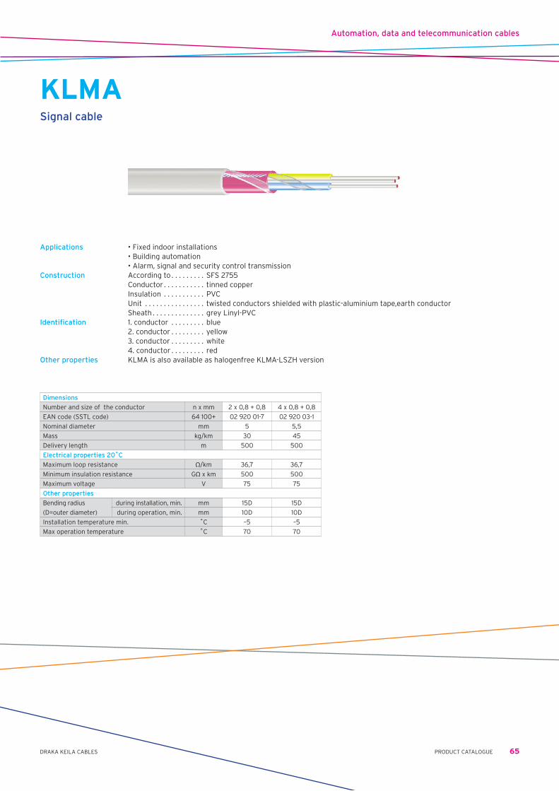
Automation, data and telecommunication cables
65PRODUCT CATALOGUEDRAKA KEILA CABLES
KLMASignal cable
Applications •Fixedindoorinstallations •Buildingautomation •Alarm,signalandsecuritycontroltransmissionConstruction According to . . . . . . . . . SFS 2755 Conductor . . . . . . . . . . . tinned copper Insulation . . . . . . . . . . . PVC Unit . . . . . . . . . . . . . . . . twisted conductors shielded with plastic-aluminium tape,earth conductor Sheath . . . . . . . . . . . . . . grey Linyl-PVCIdentification 1. conductor . . . . . . . . . blue 2. conductor . . . . . . . . . yellow 3. conductor . . . . . . . . . white 4. conductor . . . . . . . . . redOther properties KLMA is also available as halogenfree KLMA-LSZH version
Dimensions
Number and size of the conductor n x mm 2 x 0,8 + 0,8 4 x 0,8 + 0,8
EAN code (SSTL code) 64 100+ 02 920 01-7 02 920 03-1
Nominal diameter mm 5 5,5
Mass kg/km 30 45
Delivery length m 500 500
Electrical properties 20˚C
Maximum loop resistance Ω/km 36,7 36,7
Minimum insulation resistance GΩ x km 500 500
Maximum voltage V 75 75
Other properties
Bending radius during installation, min. mm 15D 15D
(D=outerdiameter) during operation, min. mm 10D 10D
Installation temperature min. ˚C –5 –5
Max operation temperature ˚C 70 70

Automation, data and telecommunication cables
66 DRAKA KEILA CABLES PRODUCT CATALOGUE
LONAKLON-network cable
Application — Fixed indoor installations — LON net cabling — Building automation cabling Designed specially for LON network cabling systems. Fire performance The cable fulfils the fire condition requirements of IEC 332-1 Construction Conductor . . . . . . . . . . . tinned copper Insulation . . . . . . . . . . . PVC Unit . . . . . . . . . . . . . . . . twisted pair Shield . . . . . . . . . . . . . . aluminium tape and earth conductor Sheath . . . . . . . . . . . . . grey LINYL-PVCIdentification Pair . . . . . . . . . . . . . . . . . conductor 1. . . . . . . . . . . . . . . . . . . . white/ blue 2 . . . . . . . . . . . . . . . . . . . white/ orangeOther properties LONAK is also available as halogenfree LONAK-HF version
Dimensions
Number and size of the conductor n x n mm 2 x 2 x 0,65 mm 2 x 2 x 0,8 mm 2 x 1,3 mm2
EAN code (SSTL code) 64 100+ 02 649 36-9 02 649 38-3 02 649 20-8
Nominal diameter mm 5,5 6,5 7,5
Mass kg/km 50 60 65
Delivery length m 1000 1000 1000
Electrical properties 20˚C
Maximum loop resistance Ω/km 106 73 28
Nominal mutual capacitance nF/km 49 98 72
Minimum insulation resistance MΩ x km 100 100 100
Velocity factor 0,55 0,67 0,55
Maximum voltage V 75 75 75
Other properties
Bending radius during installation, min. mm 15D 15D 15D
(D=outerdiameter) during operation, min. mm 10D 10D 10D
Pull strenght N max 65 65 130
Installation temperature min. ˚C –5 –5 –5
Max operation temperature ˚C 70 70 70

Automation, data and telecommunication cables
67PRODUCT CATALOGUEDRAKA KEILA CABLES
PULS 2,5 75VTraffic sensor cable
Application Trafficlight cable with a maximum voltage of 75 V (a.c.) or a maximum of 50 V (d.c.) to earth. Highest permissible conductor temperature - in continious operation . . . . . . . . . . . . . . . . . . . . . 90 °C - in a short circuit (max. 30 s) . . . . . . . . . . . . . . . . 200 °C Lowest recommended handling temperature . . —40 °CConstruction Conductor . . . . . . . . . . . . . . . annealed tinned copper wires, stranded flexible Insulation . . . . . . . . . . . . . . . heat resistant plastic Outer sheath . . . . . . . . . . . . black oil retardant rubber Standards IEC 60228, CENELEC HD 22, IEC 60332-1Certificate / approval RoHSRated voltage U=75VDC;50VACBending radius During installation min . . . .3D
Cross-section of conductor and colour PULS 2,5 MU 75 V
EAN code (SSTL code) 64 100+ 231,002
Nominal overall diameter mm 4
Total weight kg/km 30
Direct current resistance of conductor at 20 °C max. Ω/km 8.21
Minimum recommended bendung radius during installation m 0.012
Standard delivery length m 1000
Reel S4

Automation, data and telecommunication cables
68 DRAKA KEILA CABLES PRODUCT CATALOGUE
MHSIndoor telecommunication cable
Construction Conductor . . . . . . . . . . . annealed, tinned copper wire Insulation . . . . . . . . . . . PE Twinning . . . . . . . . . . . . two insulated conductors in a pair Lay-up . . . . . . . . . . . . . . stranded into units Signal wire . . . . . . . . . . red, insulated conductor Ground wire . . . . . . . . . annealed, tinned copper wire Screen . . . . . . . . . . . . . . plastic coated aluminium foil Sheath . . . . . . . . . . . . . . grey Linyl PVC
Conductor number and diameter EAN-code Nominalsheath thickness Nominal outer diameter Nominal mass Standard delivery length
mm 64 100+ mm mm kg/km m
1 x 4 x 0,5 1,0 4,5 30
drum 02 951 31-8 1000
coil 02 551 21-1 100
coil 02 551 31-0 300
3 x 2 x 0,5 1,0 5,0 36
drum 02 951 32-5 1000
coil 02 551 32-7 200
5 x 2 x 0,5 1,0 6,0 50
drum 02 951 33-2 1000
coil 02 551 33-4 150
10 x 2 x 0,5 1,0 7,6 78
drum 02 551 34-1 1000
coil 02 551 35-8 200
20 x 2 x 0,5
drum 02 551 36-5 1,0 9,5 130 1000
coil 02 551 39-6 150
30 x 2 x 0,5 02 551 37-2 1,1 11,5 185 1000
50 x 2 x 0,5 02 551 38-9 1,1 14,0 285 1000
100 x 2 x 0,5 02 551 40-2 1,2 19,0 550 1000
200 x 2 x 0,5 02 551 42-6 1,5 26,0 1030 1000
400 x 2 x 0,5 02 551 44-0 1,8 36,0 2000 500
800 x 2 x 0,5 02 551 48-8 2,2 50,0 3950 500
Electric properties (+20˚C)Loop resistance maximum 192 Ω/km
maximum average 184 Ω/kmInsulation resistance minimum 500 V, 1 min. 500 MΩkmMutual capacitance maximum 65 nF/km
maximum average 60 nF/kmCapacitance unbalance maximum 250 pF/500 m
over 30-pair cables, 95 % of values 150 pF/500 m

Automation, data and telecommunication cables
69PRODUCT CATALOGUEDRAKA KEILA CABLES
VMOHBUSakaru kabelis āra apstākļiem
Konstrukcija Conductor . . . . . . . . . . . annealed copper wire Insulation . . . . . . . . . . . PE Twinning . . . . . . . . . . . . two insulated conductors in a pair Signal wire . . . . . . . . . . red, insulated conductor Filling compound . . . . . special jelly Screen . . . . . . . . . . . . . . aluminium laminate Sheath . . . . . . . . . . . . . . black PE
Vada numurs un diametrs
EAN kods Nominālais apvalka biezums
Nominālais ārējais
diametrs
Nominālais svars
Standarta piegādes garums
mm 64 100+ mm mm kg/km m
100 x 2 x 0,4 02 565 08-9 2,2 24 600 1000
200 x 2 x 0,4 02 565 09-6 2,4 33 1150 1000
300 x 2 x 0,4 02 565 11-9 2,6 38 1600 1000
400 x 2 x 0,4 02 565 12-6 2,6 43 2100 1000
600 x 2 x 0,4 02 565 13-3 2,8 52 3000 500
800 x 2 x 0,4 02 565 14-0 3 58 3850 500
1200 x 2 x 0,4 02 565 16-4 3 71 5700 500
3 x 2 x 0,5 02 563 21-4 2 9,7 80 1000
5 x 2 x 0,5 02 564 74-7 2 11 105 1000
10 x 2 x 0,5 02 564 75-4 2 12,5 145 1000
20 x 2 x 0,5 02 564 76-1 2 15,5 235 1000
30 x 2 x 0,5 02 564 77-8 2 17,5 315 1000
50 x 2 x 0,5 02 564 78-5 2 22 480 1000
100 x 2 x 0,5 02 564 79-2 2,2 28 860 1000
200 x 2 x 0,5 02 564 80-8 2,4 39 1650 1000
300 x 2 x 0,5 02 564 81-5 2,4 45 2350 1000
400 x 2 x 0,5 02 564 82-2 2,6 52 3050 500
600 x 2 x 0,5 02 564 83-9 3 62 4500 500
800 x 2 x 0,5 02 564 84-6 3,2 71 5900 500
5 x 2 x 0,6 02 565 43-0 2 12 130 1000
10 x 2 x 0,6 02 565 44-7 2 14 185 1000
20 x 2 x 0,6 02 565 45-4 2 17,5 305 1000
30 x 2 x 0,6 02 565 46-1 2 21 425 1000
50 x 2 x 0,6 02 565 47-8 2 25 630 1000
100 x 2 x 0,6 02 565 48-5 2,2 33 1200 1000
200 x 2 x 0,6 02 565 62-1 2,6 46 2300 1000
300 x 2 x 0,6 02 565 63-8 2,6 54 3300 500
400 x 2 x 0,6 02 565 64-5 2,6 63 4400 500
10 x 2 x 0,8 02 565 50-8 2 16,5 275 1000
20 x 2 x 0,8 02 565 51-5 2 22 480 1000
30 x 2 x 0,8 02 565 52-2 2 25 680 1000
50 x 2 x 0,8 02 565 53-9 2,2 32 1100 1000
100 x 2 x 0,8 02 565 54-6 2,4 42 2000 1000
3 x 2 x 1,0 02 565 03-4 2 14 185 1000
Electric properties (+20˚C)
Number of pairs in cable
Mutual capacitance maximum, nF/km
Mutual capacitance max average nF/km
50 and more 45 40
less than 50 46 -
Vada diametrs, mm Pretestības asimetrijas maksimums, %
0,8 2
Vada diametrs, mmCilpas pretestība,
Ω/kmVidējā maksimālā cil-pas pretestība, Ω/km
0,4 300 288
0,5 192 184
0,6 134 128
0,8 74 71
Izolācijas pretestība 500 V, 1 min.
- minimālā 2 GΩ km
Vada diametrs Kapacitātes asimetrija pāris - pāris pF/500m Kapacitātes asimetrija pāris - zeme pF/500m
mm maksimālā 95% no vērtības maksimālā 95% no vērtības
0,4-0,6 250 150 - -
0,8 180 100 1700 1000
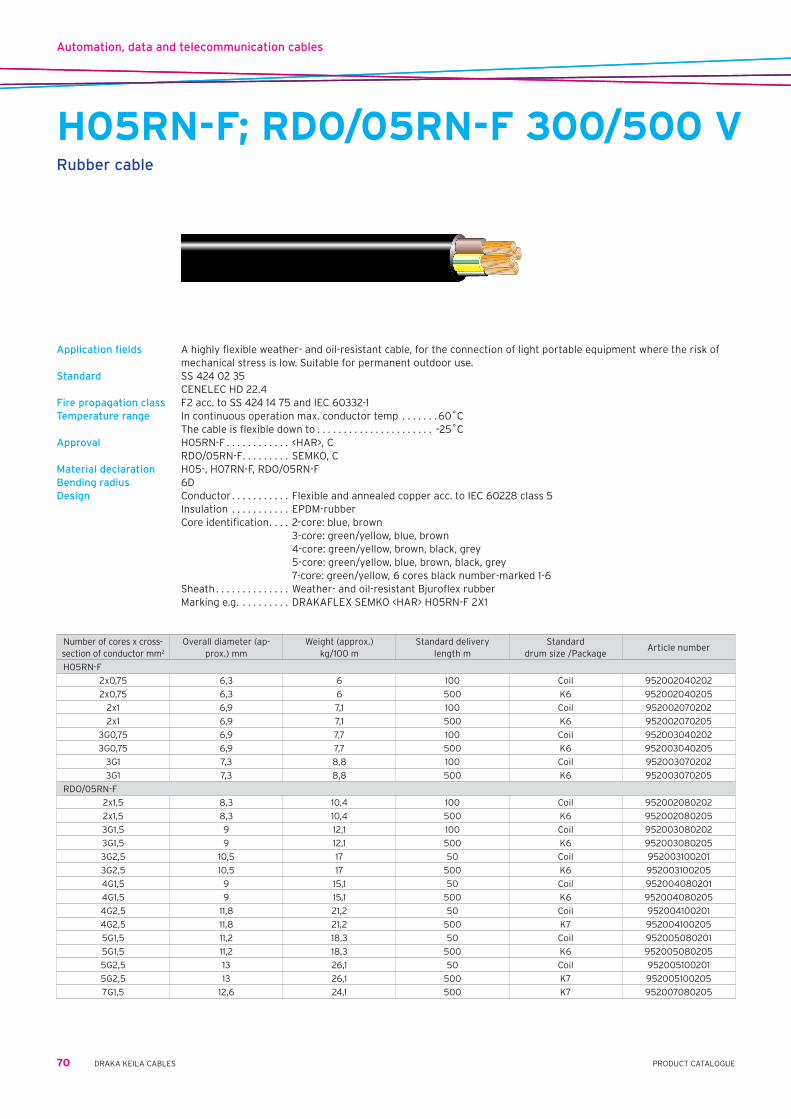
Automation, data and telecommunication cables
70 DRAKA KEILA CABLES PRODUCT CATALOGUE
H05RN-F; RDO/05RN-F 300/500 VRubber cable
Application fields A highly flexible weather- and oil-resistant cable, for the connection of light portable equipment where the risk of mechanical stress is low. Suitable for permanent outdoor use.
Standard SS 424 02 35 CENELEC HD 22.4 Fire propagation class F2 acc. to SS 424 14 75 and IEC 60332-1 Temperature range In continuous operation max. conductor temp . . . . . . .60˚C The cable is flexible down to . . . . . . . . . . . . . . . . . . . . . . –25˚C Approval H05RN-F . . . . . . . . . . . . <HAR>, C RDO/05RN-F . . . . . . . . . SEMKO, C Material declaration H05-, H07RN-F, RDO/05RN-F Bending radius 6D Design Conductor . . . . . . . . . . . Flexible and annealed copper acc. to IEC 60228 class 5 Insulation . . . . . . . . . . . EPDM-rubber Core identification . . . . 2-core: blue, brown 3-core: green/yellow, blue, brown 4-core: green/yellow, brown, black, grey 5-core: green/yellow, blue, brown, black, grey 7-core: green/yellow, 6 cores black number-marked 1-6 Sheath . . . . . . . . . . . . . . Weather- and oil-resistant Bjuroflex rubber Marking e.g. . . . . . . . . . DRAKAFLEX SEMKO <HAR> H05RN-F 2X1
Number of cores x cross-section of conductor mm2
Overall diameter (ap-prox.) mm
Weight (approx.) kg/100 m
Standard delivery length m
Standard drum size /Package
Article number
H05RN-F
2x0,75 6,3 6 100 Coil 952002040202
2x0,75 6,3 6 500 K6 952002040205
2x1 6,9 7,1 100 Coil 952002070202
2x1 6,9 7,1 500 K6 952002070205
3G0,75 6,9 7,7 100 Coil 952003040202
3G0,75 6,9 7,7 500 K6 952003040205
3G1 7,3 8,8 100 Coil 952003070202
3G1 7,3 8,8 500 K6 952003070205
RDO/05RN-F
2x1,5 8,3 10,4 100 Coil 952002080202
2x1,5 8,3 10,4 500 K6 952002080205
3G1,5 9 12,1 100 Coil 952003080202
3G1,5 9 12,1 500 K6 952003080205
3G2,5 10,5 17 50 Coil 952003100201
3G2,5 10,5 17 500 K6 952003100205
4G1,5 9 15,1 50 Coil 952004080201
4G1,5 9 15,1 500 K6 952004080205
4G2,5 11,8 21,2 50 Coil 952004100201
4G2,5 11,8 21,2 500 K7 952004100205
5G1,5 11,2 18,3 50 Coil 952005080201
5G1,5 11,2 18,3 500 K6 952005080205
5G2,5 13 26,1 50 Coil 952005100201
5G2,5 13 26,1 500 K7 952005100205
7G1,5 12,6 24,1 500 K7 952007080205

Automation, data and telecommunication cables
71PRODUCT CATALOGUEDRAKA KEILA CABLES
DRAKAFLEX H07RN-F 450/750 VRubber cable
Application fields A highly flexible weather- and oil-resistant cable. For use where the mechanical stress have medium hard character, in spaces with explosion risks or dry and damp spaces. Outdoors e.g. in agricultural buildings and for temporary installations in working sites. Also for fixed installation in temporary buildings and cabins.
Standard CENELEC HD 22.4 Fire propagation class F2 acc. to SS 424 14 75 and IEC 60332-1 Temperature range In continuous operation max. conductor temp. . . . . . . .60˚C The cable is flexible down to . . . . . . . . . . . . . . . . . . . . . . –25˚CApproval <HAR>, CEMaterial declaration H05-, H07RN-F, RDO/05RN-F Bending radius — when flexing . . . . . . . 6D — at fixed mounting . . 4DMax tensile stress (N) Total copper area x 15 Design Conductor . . . . . . . . . . . flexible and annealed copper acc. to IEC 60228 class 5 Insulation . . . . . . . . . . . EPDM-rubber Core identification . . . . 2-core: blue, brown 3-core: green/yellow, blue, brown 4-core: green/yellow, brown, black, grey 5-core: green/yellow, blue, brown, black, grey 7-core: green/yellow, 6 cores black number-marked 1-6 Sheath . . . . . . . . . . . . . . weather- and oil-resistant Bjuroflex rubber Marking e.g. . . . . . . . . . DRAKAFLEX SEMKO <HAR> H07RN-F 5G1,5
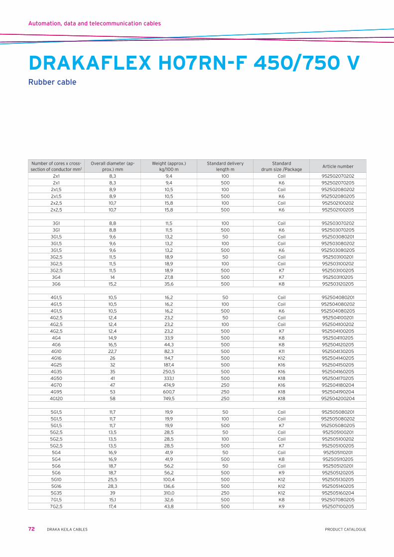
Automation, data and telecommunication cables
72 DRAKA KEILA CABLES PRODUCT CATALOGUE
Number of cores x cross-section of conductor mm2
Overall diameter (ap-prox.) mm
Weight (approx.) kg/100 m
Standard delivery length m
Standard drum size /Package
Article number
2x1 8,3 9,4 100 Coil 952502070202
2x1 8,3 9,4 500 K6 952502070205
2x1,5 8,9 10,5 100 Coil 952502080202
2x1,5 8,9 10,5 500 K6 952502080205
2x2,5 10,7 15,8 100 Coil 952502100202
2x2,5 10,7 15,8 500 K6 952502100205
3G1 8,8 11,5 100 Coil 952503070202
3G1 8,8 11,5 500 K6 952503070205
3G1,5 9,6 13,2 50 Coil 952503080201
3G1,5 9,6 13,2 100 Coil 952503080202
3G1,5 9,6 13,2 500 K6 952503080205
3G2,5 11,5 18,9 50 Coil 952503100201
3G2,5 11,5 18,9 100 Coil 952503100202
3G2,5 11,5 18,9 500 K7 952503100205
3G4 14 27,8 500 K7 952503110205
3G6 15,2 35,6 500 K8 952503120205
4G1,5 10,5 16,2 50 Coil 952504080201
4G1,5 10,5 16,2 100 Coil 952504080202
4G1,5 10,5 16,2 500 K6 952504080205
4G2,5 12,4 23,2 50 Coil 952504100201
4G2,5 12,4 23,2 100 Coil 952504100202
4G2,5 12,4 23,2 500 K7 952504100205
4G4 14,9 33,9 500 K8 952504110205
4G6 16,5 44,3 500 K8 952504120205
4G10 22,7 82,3 500 K11 952504130205
4G16 26 114,7 500 K12 952504140205
4G25 32 187,4 500 K16 952504150205
4G35 35 250,5 500 K16 952504160205
4G50 41 333,1 500 K18 952504170205
4G70 47 474,9 250 K16 952504180204
4G95 53 600,7 250 K18 952504190204
4G120 58 749,5 250 K18 952504200204
5G1,5 11,7 19,9 50 Coil 952505080201
5G1,5 11,7 19,9 100 Coil 952505080202
5G1,5 11,7 19,9 500 K7 952505080205
5G2,5 13,5 28,5 50 Coil 952505100201
5G2,5 13,5 28,5 100 Coil 952505100202
5G2,5 13,5 28,5 500 K7 952505100205
5G4 16,9 41,9 50 Coil 952505110201
5G4 16,9 41,9 500 K8 952505110205
5G6 18,7 56,2 50 Coil 952505120201
5G6 18,7 56,2 500 K9 952505120205
5G10 25,5 100,4 500 K12 952505130205
5G16 28,3 136,6 500 K12 952505140205
5G35 39 310,0 250 K12 952505160204
7G1,5 15,1 32,6 500 K8 952507080205
7G2,5 17,4 43,8 500 K9 952507100205
DRAKAFLEX H07RN-F 450/750 VRubber cable

Halogen-free and fire resistant cables
73PRODUCT CATALOGUEDRAKA KEILA CABLES
Type 2x1,5 3G1,5 4G1,5 5G1,5 7G1,5 2x2,5 3G2,5 4G2,5 5G2,5 7G2,5 4G6 5G6 4G10 5G10 4G16 5G16
Nom. Core Diam. mm 3,4 3,4 3,4 3,4 3,4 3,4 3,8 3,8 3,8 3,8 4,9 4,9 7,1 7,1 8,3 8,3
Nom. Outer Diam. mm 11,6 12,1 13,9 14,3 14,9 12,4 13,0 15,3 18,0 16,1 15,6 17,0 20,0 23,2 22,0 26,6
Weight kg/km 175 190 230 260 265 210 230 340 410 350 420 510 775 920 1000 1295
Min. bending radius mm 95 100 115 115 120 100 105 125 145 130 125 140 160 190 180 215
Max. pulling force N 400 435 575 610 665 460 505 700 970 775 730 865 1200 1610 1450 2120
Current Rating A 26 26 23 23 17 36 36 32 25 23 54 54 75 75 100 100
Conductor 20˚C ac Ω/km 12,1 12,1 12,1 12,1 12,1 12,1 7,41 7,41 7,41 7,41 3,08 3,08 1,83 1,83 1,15 1,15
Resistance 90˚C dc Ω/km 15,4 15,4 15,4 15,4 15,4 15,4 9,45 9,45 9,45 9,45 3,93 3,93 2,33 2,33 1,47 1,47
Type 4G25 5G25 4G35 5G35 4x50 5G50 4G70 5G70 5G95 4G120 5G120 4G150 4G185 4G240 1x300 1x400
Nom. Core Diam. mm 9,6 9,6 10,8 10,8 12,1 12,1 13,1 13,1 15,8 17,2 17,2 19,2 21,5 24,2 26,9 30,2
Nom. Outer Diam. mm 26,0 30,2 30,0 33,7 34,6 38,3 40,0 44,0 49,4 50,0 54,4 55,0 61,0 69,0 33,0 37,0
Weight kg/km 1450 1855 1980 2415 2660 3240 3700 4440 5970 6180 7400 7520 9360 12120 3430 4280
Min. bending radius mm 210 245 240 270 280 310 320 355 400 400 440 440 490 555 265 300
Max. pulling force N 2025 2735 2700 3405 280 310 320 355 7320 7500 8875 9075 10000 10000 3265 4105
Current Rating A 127 127 158 158 192 192 246 246 298 346 346 399 456 538 703 823
Conductor 20˚C ac Ω/km 0,727 0,727 0,524 0,524 0,387 0,387 0.268 0.268 0,193 0,153 0,153 0,124 0,0991 0,0754 0,0601 0,0470
Resistance 90˚C dc Ω/km 0,927 0,927 0,669 0,669 0,494 0,494 0.344 0.344 0,248 0,198 0,198 0,161 0,131 0,102 0,0831 0,0685
Current rating: cables in free air according to IEC 60364-5-52
HULT(FLEX) LSOH FB 90 0,6/1kVFire Resistant Halogen free Power and Control Cable
Application Halogen free Power and Control cable for Low Voltage applications 0,6/1 kV. Designed for vital installations during fire and have circuit integrity during 30 and 60 minutes. Suitable in wet environments. Multi core cables are specially applied for control engineering. Suited for use in Public buildings tunnels, Railway Stations, Oil and Petrol Chemical plants, etc where the danger to life may be greatly increased in the event of a power failure due to fire.
Properties and Circuit integrity during fire . . . . . . EN 50200 EN 50362, IEC 60331 and DIN 4102/12Specifications Flame Retardant . . . . . . . . . . . . . . . IEC 60332-3-22 (Cat A) Self extinguishing . . . . . . . . . . . . . . IEC 60332-1 Halogen free . . . . . . . . . . . . . . . . . . IEC 60754 Low Smoke . . . . . . . . . . . . . . . . . . . IEC 61034Remarks General, for signalling cables 30 minutes Circuit Integrity required and for Power cables is a minimum of 60 minutes
Circuit Integrity requiredConstruction Conductor . . . . . . . . . . . . . . . . . . . . . Solid conductor up to 10mm2
10mm2 and larger conductor sizes stranded copper Insulation . . . . . . . . . . . . . . . . . . . . . Ceramifiable Silicone rubber Earthing core green//yellow polyethylene (PE) Cores . . . . . . . . . . . . . . . . . . . . . . . . . Cores cabled together Bedding . . . . . . . . . . . . . . . . . . . . . . . Halogen free compound Outer sheet. . . . . . . . . . . . . . . . . . . . Polyolefin, halogen free compound Colour coding cores 1 core . . . . . . . . . . . . . . . . . . . . . . . . . black 2 cores . . . . . . . . . . . . . . . . . . . . . . . blue brown 3 cores . . . . . . . . . . . . . . . . . . . . . . . . blue brown green/yellow 4 cores. . . . . . . . . . . . . . . . . . . . . . . . blue brown black green/yellow blue brown black grey 5 cores . . . . . . . . . . . . . . . . . . . . . . . . blue brown black grey green/yellowOther properties Installation temperature . . . . . . . . min. –20˚C, max. +60˚C Outer sheet colour . . . . . . . . . . . . . red Delivery . . . . . . . . . . . . . . . . . . . . . . . on reels

Halogen-free and fire resistant cables
74 DRAKA KEILA CABLES PRODUCT CATALOGUE
HULT(FLEX) LSOH FB30/60 0,6/1kVFire Resistant Halogen free Power and Control Cable
Application Halogen free Power and Control cable for Low Voltage applications 0,6/1 kV. Designed for vital installations during fire and have circuit integrity during 30 and 60 minutes. Suitable in wet environments. Multi core cables are especially applied for control engineering. Suited for use in Public buildings tunnels, Railway Stations, Oil and Petrol Chemical plants, etc where the danger to life may be greatly increased in the event of a power failure due to fire.
Properties and Circuit integrity during fire: EN 50200 EN 50362, IEC 60331 and DIN 4102/12Specifications Flame Retardant . . . . . . . . . . . . . . . IEC 60332-3-22 (Cat A) Self extinguishing . . . . . . . . . . . . . . IEC 60332-1 Halogen free . . . . . . . . . . . . . . . . . . IEC 60754 Low Smoke . . . . . . . . . . . . . . . . . . . IEC 61034Remarks General, for signalling cables 30 minutes Circuit Integrity required and for Power cables is a minimum of 60 minutes
Circuit Integrity requiredConstruction Conductor . . . . . . . . . . . . . . . . . . . . . solid conductor up to 10mm2
10mm2 and larger conductor sizes stranded copper Insulation . . . . . . . . . . . . . . . . . . . . . ceramifiable Silicone rubber Earthing core green//yellow polyethylene (PE) Cores . . . . . . . . . . . . . . . . . . . . . . . . . cores cabled together Bedding . . . . . . . . . . . . . . . . . . . . . . . halogen free compound Outer sheet. . . . . . . . . . . . . . . . . . . . polyolefin, halogen free compound Colour coding cores 1 core . . . . . . . . . . . . . . . . . . . . . . . . . black 2 cores . . . . . . . . . . . . . . . . . . . . . . . blue brown 3 cores . . . . . . . . . . . . . . . . . . . . . . . . blue brown green/yellow 4 cores. . . . . . . . . . . . . . . . . . . . . . . . blue brown black green/yellow blue brown black grey 5 cores . . . . . . . . . . . . . . . . . . . . . . . . blue brown black grey green/yellowOther properties Installation temperature . . . . . . . . min. –20˚C, max. +60˚C Outer sheet colour . . . . . . . . . . . . . red Delivery . . . . . . . . . . . . . . . . . . . . . . . on reels
Type 2x1,5 3G1,5 4G1,5 5G1,5 7G1,5 2x2,5 3G2,5 4G2,5 5G2,5 7G2,5 24G2,5 5G4 4G6 5G6 5G10
Nom. Core Diam. mm 3,4 3,4 3,4 3,4 3,4 3,4 3,8 3,8 3,8 3,8 3,8 4,4 4,9 4,9 7,1
Nom. Outer Diam. mm 11,6 12,1 13,9 14,3 14,9 12,4 13,0 15,3 18,0 16,1 31,0 16,6 15,6 17,0 23,2
Weight kg/km 175 190 230 260 265 210 230 340 410 350 1280 390 420 510 920
Min. bending radius mm 95 100 115 115 120 100 105 125 145 130 250 125 125 140 190
Max. pulling force N 400 435 575 610 665 460 505 700 970 775 2880 730 730 865 1610
Current Rating A 26 26 23 23 17 36 36 32 25 23 13,5 42 54 54 75
Conductor 20˚C ac Ω/km 12,1 12,1 12,1 12,1 12,1 12,1 7,41 7,41 7,41 7,41 7,41 4,61 3,08 3,08 1,83
Resistance 90˚C dc Ω/km 15,4 15,4 15,4 15,4 15,4 15,4 9,45 9,45 9,45 9,45 9,45 5,88 3,93 3,93 2,33
Type 5G16 5G25 5G35 4G50 5G50 5G70 4G95 5G95 4G120 5G120 4G150 4G185 4G240 1x300 1x400
Nom. Core Diam. mm 8,3 9,6 10,8 12,1 12,1 13,1 15,8 15,8 17,2 17,2 19,2 21,5 24,2 26,9 30,2
Nom. Outer Diam. mm 26,6 30,2 33,7 34,6 38,3 44,0 44,6 49,4 50,0 54,4 55,0 61,0 69,0 33,0 37,0
Weight kg/km 1295 1855 2415 2670 3240 4440 4895 5970 6180 7400 7520 9360 12120 3430 4280
Min. bending radius mm 215 245 270 280 310 355 360 400 400 440 440 490 555 265 300
Max. pulling force N 2120 2735 3405 280 310 355 5965 7320 7500 8875 9075 10000 10000 3265 4105
Current Rating A 100 127 158 192 192 246 298 298 346 346 399 456 538 703 823
Conductor 20˚C ac Ω/km 1,15 0,727 0,524 0,387 0,387 0.268 0,193 0,193 0,153 0,153 0,124 0,0991 0,0754 0,0601 0,0470
Resistance 90˚C dc Ω/km 1,47 0,927 0,669 0,494 0,494 0.344 0,248 0,248 0,198 0,198 0,161 0,131 0,102 0,0831 0,0685
Current rating: cables in free air according to IEC 60364-5-52

Halogen-free and fire resistant cables
75PRODUCT CATALOGUEDRAKA KEILA CABLES
BI(c) 250VFire resistant halogen-free control cable
Application As alarm, control, and signal cables in places where during a fire the cable must sustain its functionality for a certain amount of time in order to protect people or machinery. For indoor and outdoor use.
Properties Rated voltage Um . . . . . . . . . . . . . . . . . . . . . . . . . . . . . . . . . . . . . . . . . . . .250V Max allowed temperature for the cable: - continuous use . . . . . . . . . . . . . . . . . . . . . . . . . . . . . . . . . . . . . . . . . . . . . 70˚C - in case of short circuit (max 5 sec) . . . . . . . . . . . . . . . . . . . . . . . . . . . 160˚C Min recommended usage temperature . . . . . . . . . . . . . . . . . . . . . . . . . .–15˚C Min recommended bending radius - when installing . . . . . . . . . . . . . . . . . . . . . . . . . . . . . . . . . . . . . . . . . . . . . . . 10D - for permanent installation as a one-time bend . . . . . . . . . . . . . . . . . . . . 5D Max allowed tension during installation . . . . . . . . . . . . . . . . . . Ax50 N/mm2
Certificates CE, RoHSConstruction Conductor . . . . . . . . . . . . . . . annealed, tinned copper, multi-stranded Insulation . . . . . . . . . . . . . . . Mica-tape and EPDM-rubber, colour and numerical markings Shielding . . . . . . . . . . . . . . . . aluminium/polyester band and ground wire as a unified shielding Outer sheath . . . . . . . . . . . . orange halogen-free polymer, production date and metric markingsTähistus Conductor color and pair . . BLA/BLU and number tape on pair Four core . . . . . . . . . . . . . . . . BLA/BLU and BLA/BRStandardid CENELEC HD 627-7B, IEC 60502-1, IEC 60332-3C, IEC 60331 and EN50200, IEC 60754-1 and 2, IEC 61034
Technical Data
No. of Cable Pairs/cables and Area of Cross Section mm2 2 x 0,75 1 x 4 x 0,75 2 x 2 x 0,75 4 x 2 x 0,75
Art No. 460961 460922 461110 461120
Approx. Diameter mm 6,5 8,4 10,3 11,9
Approx. Weight kg/km 70 115 140 210
Standard Lenght m 500 500 500 500
Standard Package S4 S4 K7 K7
Properties
Capacitance of the Cable Pair µF/km u 80
Inductance mH/km u 0,75
Impedance / 1 kHz Ω/km u 330
Conductor Resistivity, Max (20 ˚C) Ω/km 24,8
Loop Resistivity, Max (20 ˚C) Ω/km 49,6

Halogen-free and fire resistant cables
76 DRAKA KEILA CABLES PRODUCT CATALOGUE
BFSI-EMC 1kVHalogen-free and fire-resistant
Application Installations with rated voltage up to 1kV, in case of requirement for a cable to function during a fire. This is a cable for indoor and outdoor use. Improved EMC screen according to EMC directive. Halogen-free cable is recommended when it is important to avoid heavy smoke and corrosive gases in case of a fire. National regulations for electrical installations must be followed.
Max conductor temp . . . . . 90O˚C Rated voltage U0/U . . . . . . 0,6/1kV Cenelec designation . . . . . N1ZC7Z1-RStandards applied Construction . . . . . . . . . . . . CENELEC HD 604-5D Insulation . . . . . . . . . . . . . . IEC 60502-1 Fire resistant . . . . . . . . . . . IEC 60331 Flame retardancy . . . . . . . IEC 60332-3C Halogen-free . . . . . . . . . . . IEC 60754-1and 2 Low Smoke . . . . . . . . . . . . . IEC 61034Approvals NEMKO CE-marking, acc. to LVD.Construction Conductor . . . . . . . . . . . . . . stranded copper Insulation (B) . . . . . . . . . . . Mica-tape and extruded XLPE Bedding (F) . . . . . . . . . . . . . halogen-free Concentric conductor . . . . copperfoil with overlap and concentric screen of copper wires. (PE/PEN-conductor) Outer sheath (I) . . . . . . . . . halogen-free Polymer Colour . . . . . . . . . . . . . . . . . black Marking . . . . . . . . . . . . . . . . printed on outer sheath, designation and dimension.
Metremarking and year of production. Mode of packing . . . . . . . . drum
*)FR=Strandedround.FV=Strandedsectorshaped.Mode of packing and length can be changed.
No. of cores and conductor area mm2 2 x 1,5/1,5 2 x 2,5/2,5 2 x 6/6 3 x 1,5/1,5 3 x 2,5/2,5 3 x 4/4 3 x 6/6 3 x 10/10 3 x 16/16 3 x 25/16
Conductor type *) FR FR FR FR FR FR FR FR FR FR
El. No. 1046120 1046121 1046123 1046140 1046141 1046142 1046143 1046144 1046145 1046146
Art. No. 422605 422615 422640 422610 422620 422630 422645 422655 422660 422670
Outer diameter appr. mm 12 13 15 12 13 15 16 19 22 25
Approx. weight kg/km 150 190 300 180 220 290 380 570 860 1150
No. of cores and conductor area mm2 3 x 35/16 3 x 50/25 4 x 1,5/1,5 4 x 2,5/2,5 4 x 4/4 4 x 6/6 4 x 10/10 4 x 16/16 4 x 25/16 4 x 35/16
Conductor type *) FV FV FR FR FR FR FR FR FR FV
El. No. 1046147 1046148 1046160 1046161 1046162 1046163 1046164 1046165 1046166 1046167
Art. No. 422675 422680 422612 422625 422635 422650 422657 422665 422673 422677
Outer diameter appr. mm 24 27 13 14 16 17 21 24 27 27
Approx. weight kg/km 1380 1840 200 260 350 460 690 1050 1430 1750
No. of cores and conductor area mm2 4 x 50/25 4 x 70/35 4 x 95/50 4 x 150/70
Conductor type *) FV FV FV FV
El. No. 1046168 1046169 1046170 1046172
Art. No. 422685 422690 422693 422695
Outer diameter appr. mm 30 36 40 48
Approx. weight kg/km 2330 3280 4500 6700

Halogen-free and fire resistant cables
77PRODUCT CATALOGUEDRAKA KEILA CABLES
HULT(FLEX) LSOH 0,6/1kVHalogen free Power and Control Cable
Application Halogen free Power and Control cable for Low Voltage applications 0,6/1 kV Suitable in wet environments Multi core cables are especially applied for control engineering Suited for use in Public buildings tunnels, Railway Stations, Oil and Petrol Properties and Specifications Circuit integrity during fire . . . . . . EN 50200 EN 50362, IEC 60331 Flame Retardant . . . . . . . . . . . . . . . IEC 60332-3-22 (Cat A) Self extinguishing . . . . . . . . . . . . . . IEC 60332-1 Halogen free . . . . . . . . . . . . . . . . . . . IEC 60754 Low Smoke . . . . . . . . . . . . . . . . . . . . IEC 61034Construction Conductor . . . . . . . . . . . . . . . . . . . . . Solid conductor up to 10mm2
10mm2 and larger conductor sizes stranded copper Insulation . . . . . . . . . . . . . . . . . . . . . polyethylene (PE) Cores . . . . . . . . . . . . . . . . . . . . . . . . . Cores cabled together Bedding . . . . . . . . . . . . . . . . . . . . . . . Halogen free compound Outer sheet. . . . . . . . . . . . . . . . . . . . Polyolefin, halogen free compound
Colour coding cores 1 core . . . . . . . . . . . . . . . . . . . . . . . . . black 2 cores . . . . . . . . . . . . . . . . . . . . . . . blue brown 3 cores . . . . . . . . . . . . . . . . . . . . . . . . blue brown green/yellow 4 cores. . . . . . . . . . . . . . . . . . . . . . . . blue brown black green/yellow blue brown black grey 5 cores . . . . . . . . . . . . . . . . . . . . . . . . blue brown black grey green/yellow
Other properties Min. installation temperature . . . . –20˚C, max. +60˚C Max. conductor temperature . . . . . 90˚C Outer sheet colour . . . . . . . . . . . . . red Delivery . . . . . . . . . . . . . . . . . . . . . . . on reels
Type 5G2,5 5G4 5G6 5G10 5G16 5G25 5G35 5G50 5G70 5G95 5G120 5G150 7G1,5 7G2,5 12G1,5 12G2,5 24G1,5
Nom. outer Diam. mm 12,5 13,7 15,0 18,7 21,5 26,2 29,5 34,9 40,5 46,5 51,4 57,6 12,0 13,1 15,2 16,8 20,2
Weight kgkm 260 350 460 745 1080 1655 2160 2990 4180 5710 7130 8900 215 285 330 440 585
Min. bending radius mm 75 85 90 115 155 185 150 175 205 235 260 290 60 80 95 105 145
Current Rating A 32 42 54 75 100 127 158 192 246 298 346 399 17 23 13 18 9,5
Conductor 20°C ac Ω/km 7,41 4,61 3,08 1,83 1,15 0,727 0,524 0,387 0,268 0,193 0,153 0,124 12,1 7,41 12,1 7,41 12,1
Resistance 90°C dc Ω/km 9,45 5,88 3,93 2,33 1,47 0,927 0,669 0,494 0,344 0,248 0,198 0,161 15,4 9,45 15,4 9,45 15,4
Working inductance mH/km 0,38 0,36 0,34 0,32 0,31 0,30 0,30 0,27 0,23 0,22 0,21 0,20 - - - - -
Working capacitance nF/km 147 155 164 190 217 232 243 245 247 268 280 285 ≤ 150 ≤ 150 ≤ 150 ≤ 150 ≤ 150
Type 2x1,5 2x2,5 3G1,5 3G2,5 4G1,5 4G2,5 4G4 4G6 4G10 4G16 4G25 4G35 4G50 4G70 4G95 4G150 5G1,5
Nom. outer Diam. mm 9,5 10,3 9,9 10,7 10,7 11,5 12,6 13,8 17,1 19,7 23,8 26,7 31,6 36,6 41,8 51,3 11,5
Weight kgkm 130 165 150 190 175 220 295 390 620 895 1360 1770 2445 3410 4550 7180 200
Min. bending radius mm 50 55 50 55 55 60 80 85 105 120 170 135 160 185 210 260 60
Current Rating A 26 36 26 36 23 32 42 54 75 100 127 158 192 246 298 399 23
Conductor 20°C ac Ω/km 12,1 7,41 12,1 7,41 12,1 7,41 4,61 3,08 1,83 1,15 0,727 0,524 0,387 0,268 0,193 0,124 12,1
Resistance 90°C dc Ω/km 15,4 9,45 15,4 9,45 15,4 9,45 5,88 3,93 2,33 1,47 0,927 0,669 0,494 0,344 0,248 0,161 15,4
Working inductance mH/km 0,33 0,31 0,33 0,31 0,37 0,35 0,33 0,32 0,29 0,28 0,28 0,26 0,25 0,25 0,25 0,24 0,41
Working capacitance nF/km 55 63 56 63 123 142 150 159 185 212 227 240 242 245 255 270 128

Halogen-free and fire resistant cables
78 DRAKA KEILA CABLES PRODUCT CATALOGUE
TI(c) 1000VFlame retardant halogen-free power and control cable. Unbraided, but shielded. TI (c) 1000V XLPE/PO
Application Unarmoured shielded cable for fixed installation in ships where cable protection is not required. Control cables and small power ables. Can be installed and operated both indoors and outdoors.
Operating temperature . . . . . . . .90˚C Operating Voltage . . . . . . . . . . . . .0,6/1 kVStandards applied IEC 60092-353 – Design IEC 60332-1 – Flame Retardant IEC 60228 class 2 – Conductor IEC 60332-3-22 – Flame Retardant IEC 60092-351 – Insulation IEC 60754-1,2 – Halogen Free IEC 60092-359 – Sheath IEC 61034-1,2 – Low SmokeConstruction Conductor . . . . . . . . . . . . . . . . . . . .annealed stranded circular copper, IEC 60228 class 2 Insulation (T) . . . . . . . . . . . . . . . . .crosslinked Polyethylene, IEC 60092-351 (HFXLPE) Lay up / Shielding . . . . . . . . . . . . .cores are laid up in concentric layers and wrapped with a PETP tape.
Overall shielded by copper backed polyester tape with tinned copper drain wire, 1,5 mm2 conductor area.
Inner covering . . . . . . . . . . . . . . . .no inner covering. (additional tapes may be applied) Armour/screen . . . . . . . . . . . . . . . .no armour. Outer sheath (I) . . . . . . . . . . . . . . .flame retardant halogen-free thermoplastic compound, SHF1 Marking text . . . . . . . . . . . . . . . . . .e.g. “meter” “year” DRAKA TI(c) 1000V 3 x 1,5 mm2 IEC 60332-3-22 ShipLine Outer sheath colour . . . . . . . . . . .blackCore identification Control cables, 1,5 mm2 and 2,5 mm2 . . . white cores, numbered with black numbers Power cables . . . . . . . . . . . . . . . . . . . . . . . two cores + earth (3G) — Yellow/green – Blue – Brown three cores — Brown – Black – Grey three cores + earth (4G) — Yellow/green – Brown – Black – Grey four cores + earth (5G) — Yellow/green – Blue – Brown – Black – GreyInstallation Minimum Bending Radius during Installation . . . . . . . . . . . 8D Minimum Bending Radius Fixed Installed . . . . . . . . . . . . . . 6D Maximum Tensile Load During Installation . . . . . . 50 N /mm2
Minimum Installation Temperature . . . . . . . . . . . . . . . . . -10˚C
Ambient temperature correction factors
Ambient Temp˚C 35 40 45 50 55 60 65 70 75 80
Rating factor 1,10 1,05 1,00 0,94 0,88 0,82 0,74 0,67 0,58 0,47
Range and dimensions
Number of elements 2 3G 3 4G 4 5 7 12 19
Cross section core mm2 1,5 1,5 1,5 1,5 1,5 1,5 1,5 1,5 1,5
Conductor diameter mm 1,6 1,6 1,6 1,6 1,6 1,6 1,6 1,6 1,6
Insulation thickness mm 0,7 0,7 0,7 0,7 0,7 0,7 0,7 0,7 0,7
Thickness outer sheath mm 1,1 1,1 1,1 1,1 1,1 1,1 1,2 1,3 1,4
Diameter outer sheath mm 8,5 ± 0,5 9 ± 0,5 9 ± 0,5 10 ± 0,8 10 ± 0,8 11 ± 0,8 12 ± 0,8 15,5 ± 0,8 18,5 ± 0,8
Weight of cable approx. kg/km 100 120 120 145 145 170 220 340 500
Copper content approx. kg/km 41 55 55 68 68 82 110 180 277

Halogen-free and fire resistant cables
79PRODUCT CATALOGUEDRAKA KEILA CABLES
Range and dimensions
Number of elements 5G 5 3 3 3 3 3 3
Cross section core mm2 2,5 2,5 4 6 10 16 25 35
Conductor diameter mm 2,0 2,0 2,55 3,15 4,05 5,15 6,4 7,6
Insulation thickness mm 0,7 0,7 0,7 0,7 0,7 0,7 0,9 0,9
Thickness outer sheath mm 1,2 1,2 1,2 1,2 1,3 1,3 1,5 1,6
Diameter outer sheath mm 12 ± 0,8 12 ± 0,8 11,5 ± 0,8 12,5 ± 0,8 15 ± 0,8 17,5 ± 0,8 21 ± 1 24 ± 1
Weight of cable approx. kg/km 245 235 220 285 420 620 920 1230
Copper content approx. kg/km 127 127 123 183 285 449 704 962
Electrical values power cables
Number of elements 2 3G 3 4G 4 5 7 12 19
Cross section core mm2 1,5 1,5 1,5 1,5 1,5 1,5 1,5 1,5 1,5
Conductor type 2 SCC SCC SCC SCC SCC SCC SCC SCC SCC
Max. conductor resistance at 20˚C Ω/km 12,1 12,1 12,1 12,1 12,1 12,1 12,1 12,1 12,1
Max. conductor resistance at 90˚C Ω/km 15,428 15,428 15,428 15,428 15,428 15,428 15,428 15,428 15,428
Reactance at 50Hz Ω/km 0,099 0,099 0,099 0,099 0,099 0,099 0,099 0,099 0,099
Reactance at 60Hz Ω/km 0,119 0,119 0,119 0,119 0,119 0,119 0,119 0,119 0,119
Current rating IEC 60092-352 Table B.4 A 20 20 16 16 16 13,5 12 10 8,5
Short circuit rating 1 second A 210 210 210 210 210 210 210 210 210
Electrical values power cables
Number of elements 24 27 37 32 2 3G 3 4G 4
Cross section core mm2 1,5 1,5 1,5 1,5 2,5 2,5 2,5 2,5 2,5
Conductor type 2 SCC SCC SCC SCC SCC SCC SCC SCC SCC
Max. conductor resistance at 20˚C Ω/km 12,1 12,1 12,1 12,1 7,41 7,41 7,41 7,41 7,41
Max. conductor resistance at 90˚C Ω/km 15,428 15,428 15,428 15,428 9,448 9,448 9,448 9,448 9,448
Reactance at 50Hz Ω/km 0,099 0,099 0,099 0,099 0,093 0,093 0,093 0,093 0,093
Reactance at 60Hz Ω/km 0,119 0,119 0,119 0,119 0,111 0,111 0,111 0,111 0,111
Current rating IEC 60092-352 Table B.4 A 8 7,5 7 6,5 26 26 21 21 21
Short circuit rating 1 second A 210 210 210 210 350 350 350 350 350
Electrical values power cables
Number of elements 5G 5 3 3 3 3 3 3
Cross section core mm2 2,5 2,5 4 6 10 16 25 35
Conductor type 2 SCC SCC SCC SCC SCC SCC SCC SCC
Max. conductor resistance at 20˚C Ω/km 7,41 7,41 4,61 3,08 1,83 1,15 0,727 0,524
Max. conductor resistance at 90˚C Ω/km 9,448 9,448 5,878 3,927 2,333 1,466 0,927 0,668
Reactance at 50Hz Ω/km 0,093 0,093 0,087 0,082 0,078 0,074 0,075 0,073
Reactance at 60Hz Ω/km 0,111 0,111 0,104 0,099 0,093 0,089 0,09 0,087
Current rating IEC 60092-352 Table B.4 A 21 17,5 28 36 50 67 89 110
Short circuit rating 1 second A 350 350 560 840 1400 2240 3500 4900
Range and dimensions
Number of elements 24 27 37 32 2 3G 3 4G 4
Cross section core mm2 1,5 1,5 1,5 1,5 2,5 2,5 2,5 2,5 2,5
Conductor diameter mm 1,6 1,6 1,6 1,6 2,0 2,0 2,0 2,0 2,0
Insulation thickness mm 0,7 0,7 0,7 0,7 0,7 0,7 0,7 0,7 0,7
Thickness outer sheath mm 1,5 1,5 1,6 1,6 1,1 1,1 1,1 1,1 1,1
Diameter outer sheath mm 21,5 ± 1 22 ± 1 24,5 ± 1 24 ± 1 9,5 ± 0,5 10 ± 0,8 10 ± 0,8 11 ± 0,8 11 ± 0,8
Weight of cable approx. kg/km 620 680 910 820 130 160 160 195 195
Copper content approx. kg/km 347 389 530 459 59 82 82 104 104
TI(c) 1000VFlame retardant halogen-free power and control cable. Unbraided, but shielded. TI (c) 1000V XLPE/PO

Halogen-free and fire resistant cables
80 DRAKA KEILA CABLES PRODUCT CATALOGUE
IXXI 1kVHalogen-free connection cable with copper conductor SAFETY CABLE
Application Connection cable, for installation outdoor and indoor. Maximum conductor temperature in a short circuit is 160˚C. Halogen-free cabel is recomended used when it is
important to avoid heavy smoke and corrosive gases in case of fire. National regulations for electrical installations must be followed.
Max conductortemp . . 90˚C Rated voltage U0/U . . . 0,6/1 kV Cenelec designation . . N1Z1Z1-R (K)Standards applied Construction . . . . . . . . . IEC 60502-1 Materials . . . . . . . . . . . . CENELEC HD 604 Flame retardancy . . . . yes, IEC 60332-3C Halogen-free . . . . . . . . yes, IEC60754-1 and 2 Low Smoke . . . . . . . . . . yes, IEC 61034Approvals NEMKO CE-marked, acc. to LVDConstruction Conductor . . . . . . . . . . . stranded or multistranded copper Insulation . . . . . . . . . . . halogen-free Polymer Outer sheath . . . . . . . . halogen-free Polymer Marking . . . . . . . . . . . . . printed on outer sheath designation and dimensions. Metre and year. Mode of delivery . . . . . drum
*)FR=StrandedroundMR=MultistrandedroundNot all dimensions are in stock
Dimensions
Conductor area n x mm2 1 x 16 1 x 25 1 x 35 1 x 50 1 x 70 1 x 95 1 x 120 1 x 150 1 x 185 1 x 240 1 x 300
Conductor type *) FR FR FR FR FR FR MR MR MR MR MR
Outer diamter approx. mm mm 10 12 13 15 17 19 23 25 28 32 35
Approx. weight kg/km kg/km 230 340 440 590 810 1090 1330 1660 2020 2680 3250

Halogen-free and fire resistant cables
81PRODUCT CATALOGUEDRAKA KEILA CABLES
EQLQ 450/750 VHalogen-free installation cable
Application fields Halogen free, no emittance of corrosive gases, low smoke density in case of fire. Fixed installation, indoors and outdoors, in pipes, ducts, in or under plaster, also suspended in catenary system. In ground, only if the cable is protected against mechanical damage.
Alternative designation N07Z1A5EZ1-UStandard SS 424 02 19-4 in applicable parts HD 604 (Halogen free materials) EN 50267-2-2 (corrosive gases) EN 50268-2 (smoke density) Fire propagation class F3 acc. to SS 424 14 75 and IEC 60332-1 and SS-EN 50265-2-1Temperature range In continuous operation max. conductor temp 70˚C. Lowest cable temperature under installation: –15˚C and below 0˚C special precaution shall be taken.Approval SEMKO, S-marked, CEMaterial declaration EQLQPVC alternative EKLKBending radius 12D (6D in final installation, bent only once)Design Conductor . . . . . . . . . . . . .solid and annealed copper acc. to IEC 60228 class 1 Insulation . . . . . . . . . . . . .halogen free polymer Core identification . . . . . .3-core: green/yellow, blue, brown 4-core: green/yellow, blue, brown, black 5-core: green/yellow, blue, brown, black, grey Filler: Halogen free polymer Concentric conductor . . .aluminium with bonded PE in contact with drain wire of tinned copper Sheath . . . . . . . . . . . . . . . .halogen free polymer, white, metre-marked Marking e.g. . . . . . . . . . . .EQLQ 3G1,5 450/750 V F3 LSZH DRAKA S
Number of cores x cross-section of conductor n x mm2 3G1,5 3G1,5 3G1,5 3G2,5 3G2,5 3G2,5
Overall diameter (approx.) mm 9,9 9,9 9,9 11,8 11,8 11,8
Weight (approx.) kg/100 m 13,2 13,2 13,2 18,7 18,7 18,7
Standard delivery length m 50 250 500 50 150 500
Standard drum size/package Coil K4,5 K6 Coil K4,5 K7
Article number 0460001 0460003 0460005 0460011 0460013 0460015
Number of cores x cross-section of conductor mm2 4G1,5 4G1,5 4G1,5 4G2,5 4G2,5 5G1,5
Overall diameter (approx.) mm 11,2 11,2 11,2 13,3 13,3 12,0
Weight (approx.) kg/100 m 17,2 17,2 17,2 26,1 26,1 17,8
Standard delivery length m 50 200 500 50 500 50
Standard drum size/package Coil K4,5 K6 Coil K7 Coil
Article number 0460021 0460023 0460025 0460031 0460035 0460041
Number of cores x cross-section of conductor mm2 5G1,5 5G1,5 5G2,5 5G2,5 5G2,5
Overall diameter (approx.) mm 12,0 12,0 13,6 13,6 13,6
Weight (approx.) kg/100 m 17,8 17,8 26,8 26,8 26,8
Standard delivery length m 150 500 50 150 500
Standard drum size/package K4,5 K7 Coil K4,5 K7
Article number 0460043 0460045 0460051 0460053 0460055

Halogen-free and fire resistant cables
82 DRAKA KEILA CABLES PRODUCT CATALOGUE
FQLQ 450/750 VHalogen-free installation cable
Application fields Halogen free, no emittance of corrosive gases, low smoke density in case of fire. Fixed installation, indoors and outdoors, in pipes, ducts, in or under plaster, also suspended in catenary system. In ground, only if the cable is protected against mechanical damage.
Alternative designation N07Z1A5EZ1-RStandard SS 424 02 19-4 in applicable parts HD 604 (Halogen free materials) IEC 60754-1, –2 (corrosive gases) IEC 61034 (smoke density)Fire propagation class F3 acc. to SS 424 14 75 and IEC 60332-1 & EN 50265-2-1Temperature range In continuous operation max. conductor temp 70˚C Lowest cable temperature under installation –15˚C and below 0˚C special precaution shall be taken.Approval SEMKO, S-marked CEMaterial declaration EQLQ, FQLQBending radius 12D (6D in final installation, bent only once)Design Conductor . . . . . . . . . . . . . stranded and annealed copper acc. to IEC 60228 class 2 Insulation . . . . . . . . . . . . . halogen free compound Core identification . . . . . . 3-core: green/yellow, blue, brown 4-core: green/yellow, blue, brown, black 5-core: green/yellow, blue, brown, black, grey 7-core: green/yellow, 6 cores black number-marked 1-6 Filler . . . . . . . . . . . . . . . . . . halogen free compound Concentric conductor . . . aluminium with bonded PE in contact with drain wire of tinned copper Sheath . . . . . . . . . . . . . . . . halogen free compound, white, metre-marked Marking e.g. . . . . . . . . . . . FQLQ 5G2,5 450/750 V LSZH DRAKA SE F3 S
Number of cores x cross-section of conductor n x mm2 3G1,5 3G2,5 4G1,5 5G1,5 5G2,5
Overall diameter (approx.) mm 10,3 12,4 11,6 12,4 14,1
Weight (approx.) kg/100 m 15,7 20,7 18,0 20,6 28,5
Standard delivery length m 500 500 500 500 500
Standard drum size/Package K6 K7 K7 K7 K7
Articlenumber 517503080105 517503100105 517504080105 517505080105 517505100105
Number of cores x cross-section of conductor n x mm2 7G1,5 7G2,5
Overall diameter (approx.) mm 13,0 15,4
Weight (approx.) kg/100 m 24,5 34,9
Standard delivery length m 500 500
Standard drum size/Package K7 K8
Articlenumber 517507080105 517507100105

Halogen-free and fire resistant cables
83PRODUCT CATALOGUEDRAKA KEILA CABLES
AXQJ 0,6/1 kVHalogen-free power cable
Application fields Halogen free and fire classified cable. No emittance of corrosive gases, low smoke density in case of fire. Open, fixed installation, indoors and outdoors, in pipes and in ground/water. In switchgear rooms and rooms where explosions may occur. Can be carefully ploughed down.
Alternative designation SE-N1Z1CZ1-ASStandard SS 424 14 18 CENELEC HD 603 Part 3 Section L CENELEC HD 604 (Halogen free materials) IEC 60754-1, –2 (corrosive gases) IEC 61034 (smoke density)Fire propagation class F3 acc. to SS 424 14 75 and IEC 60332-1 and SS-EN 50265-2-1Temperature range In continuous operation max. conductor temp 70˚C Lowest cable temperature under installation: –20˚C and below 0˚C special precaution shall be taken.Approval SEMKO, S-marked ECMaterial declaration AXQJPVC alternative AKKJBending radius At fixed mounting . . . . . . 8D At pulling-in . . . . . . . . . . . 12D At ploughing-down . . . . . 8DDesign Conductor . . . . . . . . . . . . . stranded, sector-shaped and annealed aluminium acc. to IEC 60228 class 2 Insulation . . . . . . . . . . . . . halogen free compound Core identification . . . . . . 3-core: brown, black, grey 4-core: brown, black, grey, blue Filler . . . . . . . . . . . . . . . . . . halogen free, extruded compound or plastic tape Concentric conductor . . . annealed copper wires and counter spiral of copper Sheath . . . . . . . . . . . . . . . . halogen free compound, black Marking e.g. . . . . . . . . . . . AXQJ 0,6/1 kV 3x240/72 F3 S GREEN LINE CABLES DRAKA SE “Date”, metre marked
Number of cores x cross-section of conductor mm2 3x50/15 3x70/21 3x95/29 3x120/41 3x150/41 3x185/57 3x240/72
Overall diameter (approx.) mm 26,4 29,9 33,5 37,4 40,8 45,4 49,7
Weight (approx.) kg/100 m 92,1 122,6 158,0 176,0 208,5 265,1 333,8
Standard delivery length m 500 500 500 500 500 500 500
Standard drum size K12 K12 K14 K16 K18 K20 K22
Articlenumber 0001620 0001630 0001640 0001650 0001660 0001670 0001680
Number of cores x cross-section of conductor mm2 4x50/15 4x70/21 4x95/29 4x120/41 4x150/41 4x185/57 4x240/72
Overall diameter (approx.) mm 29,7 33,6 37,7 42,2 46,2 51,3 56,2
Weight (approx.) kg/100 m 112,7 150,5 194,5 217,1 261,4 329,4 415,2
Standard delivery length m 500 500 500 500 500 500 500
Standard drum size K12 K16 K16 K18 K18 K20 K22
Articlenumber 0001720 0001730 0001740 0001750 0001760 0001770 0001780

EXQJ 0,6/1 kVHalogen-free power cable
Application fields Halogen free, no emittance of corrosive gases, low smoke density in case of fire. Open, fixed installation, indoors and outdoors, in pipes and in ground/water. In switchgear rooms and rooms where explosions may occur. Can be carefully ploughed down.
Alternative designation SE-N1Z1CZ1-UStandard SS 424 14 18 CENELEC HD 603 Part 3 Section L CENELEC HD 604 (Halogen free materials) IEC 60754-1, –2 (corrosive gases) IEC 61034 (smoke density)Fire propagation class F3 acc. to SS 424 14 75 and IEC 60332-1Temperature range In continuous operation max. conductor temp 70˚C. Lowest cable temperature under installation: –20˚C and below 0˚C special precaution shall be taken.Approval SEMKO, S-marked CEMaterial declaration EXQJ, FXQJPVC alternative EKKJBending radius At fixed mounting . . . . . . 8D At pulling-in . . . . . . . . . . . 12D At ploughing-down . . . . . 8DDesign Conductor . . . . . . . . . . . . . solid, round and annealed copper acc. to IEC 60228 class 1 Insulation . . . . . . . . . . . . . halogen free compound Core identification . . . . . . 3-core: brown, black, grey 4-core: brown, black, grey, blue Filler . . . . . . . . . . . . . . . . . . halogen free compound Concentric conductor . . . annealed copper wires and counter spiral of copper Sheath . . . . . . . . . . . . . . . . halogen free compound, black, metre-marked Marking e.g. . . . . . . . . . . . EXQJ 3X4/4 0,6/1 kV F3 S GREEN LINE CABLES DRAKA SE “year”
Nominal values unless otherwise specified.
Number of cores x cross-section of conductor mm2 3x2,5/2,5 3x4/4 3x6/6 3x10/10
Overall diameter (approx.) mm 14 15 16 18,3
Weight (approx.) kg/100 m 24,5 31,9 41 61,3
Standard delivery length m 500 500 500 500
Standard drum size K07 K07 K08 K09
Articlenumber 2110031002 2110031102 2110031202 2110031302
Number of cores x cross-section of conductor mm2 4x2,5/2,5 4x4/4 4x6/6 4x10/10
Overall diameter (approx.) mm 14,8 15,9 17,7 19,6
Weight (approx.) kg/100 m 28,1 37 50,7 72,8
Standard delivery length m 500 500 500 500
Standard drum size K07 K07 K09 K11
Articlenumber 2110041002 2110041102 2110041202 2110041302
Halogen-free and fire resistant cables
84 DRAKA KEILA CABLES PRODUCT CATALOQUE

Nominal values unless otherwise specified.
FXQJ 0,6/1 kVHalogen free power cable
Application fields Halogen free, no emittance of corrosive gases, low smoke density in case of fire. Open, fixed installation, indoors and outdoors, in pipes and in ground/water. In switchgear rooms and rooms where explosions may occur. Can be carefully ploughed down.
Alternative designation SE-N1Z1CZ1-R SE-N1Z1CZ1-SStandard SS 424 14 18 CENELEC HD 603 Part 3 Section L CENELEC HD 604 (Halogen free materials) IEC 60754-1, –2 (corrosive gases) IEC 61034 (smoke density)Fire propagation class F3 acc. to SS 424 14 75 and IEC 60332-1Temperature range In continuous operation max. conductor temp 70˚C. Lowest cable temperature under installation: –20˚C and below 0˚C special precaution shall be taken.Approval SEMKO, S-marked CEMaterial declaration EXQJ, FXQJPVC-alternative FKKJBending radius At fixed mounting . . . . . . 8D At pulling-in . . . . . . . . . . . 12D At ploughing-down . . . . . 8DDesign Conductor . . . . . . . . . . . . . Stranded and annealed copper acc. to IEC 60228 class 2 ≤ 35 mm2 round 50-240 mm2 sector-shaped Insulation . . . . . . . . . . . . . halogen free compound Core identification . . . . . . 3-core: brown, black, grey 4-core: brown, black, grey, blue Filler . . . . . . . . . . . . . . . . . . halogen free, extruded compound or plastic tape Concentric conductor . . . annealed copper wires and counter spiral of copper Sheath . . . . . . . . . . . . . . . . halogen free compound, black, metre-marked Marking e.g. . . . . . . . . . . . FXQJ 3X240/120 0,6/1 kV F3 (S) GREEN LINE CABLES DRAKA SE “year”
Number of cores x cross-section of conductor mm2 3x16/16 3x25/16 3x35/16 3x50/25 3x70/35 3x95/50 3x120/70
Overall diameter (approx.) mm 20,6 23,4 25,8 26,4 29,9 34,3 37,6
Weight (approx.) kg/100 m 94 128,2 162,1 189,8 244,8 332,6 419,5
Standard delivery length m 500 500 500 500 500 500 500
Standard drum size K11 K11 K11 K11 K14 K14 K14
Articlenumber 2115031402 2115031502 2115031602 2115031702 2115031802 2115031902 2115032002
Number of cores x cross-section of conductor mm2 3x150/70 3x185/95 3x240/120 4x16/16 4x25/16 4x35/16 4x50/25
Overall diameter (approx.) mm 41 46,4 51,1 22,3 25,4 28,1 29,7
Weight (approx.) kg/100 m 506,6 633,9 829 112 155,7 198,7 239,8
Standard delivery length m 500 500 500 500 500 500 500
Standard drum size K18 K18 K22 K11 K12 K12 K12
Articlenumber 2115032102 2115032202 2115032302 2115041402 2115041502 2115041602 2115041702
Number of cores x cross-section of conductor mm2 4x70/35 4x95/50 4x120/70 4x150/70 4x185/95 4x240/120
Overall diameter (approx.) mm 33,7 38,6 42,3 46,5 52,6 57,6
Weight (approx.) kg/100 kg/100 m 312,4 424,4 533,5 650,6 811 1060,6
Standard delivery length m 500 500 500 500 500 500
Standard drum size K12 K16 K16 K18 K20 K22
Articlenumber 2115041802 2115041902 2115042002 2115042102 2115042202 2115042302
Halogen-free and fire resistant cables
85PRODUCT CATALOQUEDRAKA KEILA CABLES

Drum handling guideThe right way to transport, handle and move drums
A cable is a valuable product. The cable transportation package is usually a drum. The battens on the drum seem thick enough to remain unbroken. But, with a cable weighing more than 4 tons, it becomes very vulnerable. If the handling is done correctly, the drum will protect the cable from transportation damages. If the drum is damaged, the cable can also be damaged. The damage might not be discovered until after installation, when repairs can be extremely expensive.
The purpose of these instructions is to tell you how damages can be avoided by correct drum handling.
Roll in direction of arrows only.
Always roll the drum in direction of the arrow. This way the cable will not unwind and loosen on the drum. But, this does not mean that the drum can be rolled freely. When the drum must be rolled for some reason or other, roll it in the direction of arrow over a distance not exceeding 5 meters. If it is rolled beyond the 5m limit, the cable wind will come too tight and cut off the rope holding the cable end. This will deform the cable and make it unfit for use.
drum. Keep the drum from touching other drums and well balanced. Take care not to give any impact to the drum being lowered. In case a cable drum must be temporarily in a waiting position above the deck for reason of cargo handling, keep it hoisted and do not put it down on the deck.
Keep the drum upright.
Always store and move the drum in an upright position. The drum is constructed to be handled in an upright position - it will not stand up to being lifted lying flat. When kept upright, the cable layers will not entangle and cause problems when the cable is layed. Keep the cable protected until the cable is used.
Direction of rolling
Direction of unwinding
Handling with fork-lift truck.
The forks of the truck must be longer than the width of the drum, so that the lagging is not damaged. Different widths of drums should be painted on the forks enabling the operator to select the correct position for the drum size. When moving the drum, tilt the truck mast so that the drum remains in the fork and the points don´t touch the ground. Raise the forks of the forklift sufficiently 15-20 cm above the ground. Insufficient raising may cause the drum to be dragged on the ground and eventually damaged or dropped off the forks if the ground surface is uneven. Don´t release the drum until the truck has sopped completely. Don´t push the drum with the truck. Leave sufficient room between each drum so that the fork doesn´t damage the drum.
Nail with caution.
In case the planks have to be refastened, the nailing should be done carefully in the middle of the drum flange. If label or something similar is attached to the drum with nails, make sure that they don´t touch the cable.
Lift the drum without damage.
When lifting the drum, use a shaft through the centre of the drum and a wire spreader. If these are not available, lift with as long a wire as possible, so that the sides of the drum are not damaged. Make sure that the cable head is not pinched between wire and
Drums
86 DRAKA KEILA CABLES PRODUCT CATALOQUE

Secure the drums firmly.
The round-shaped cable drum rolls easily. It is an a very unstable state because its center section is vacant and the whole weight rests on its peripheral section. Make sure to use drags to prevent drums from rolling during storage. Large drums should be lifted from the base onto triangular or square wedges. The wedges should be posi-tioned by the flanges or the full width of drum. Sideways movement is eliminated by planks attached to the side of the drum. In case smaller drums are placed between larger ones, each drum has to be supported separately to prevent damages.
Avoid stacking.
Stacking of drums should be avoided. If, however, one is forced to do this, same size of drums should be positioned exactly on top of each other.If smaller drums are stacked on larger drums, planks of the size of the larger drum is placed in between to protect the flanges. Above method is recommended even when same size drums are stacked..
Fasten the drums firmly.
The drum is fastened to the base through the centre hole or across the flanges with wires or ropes.
Secure drums to be transported.
To prevent movement of drums, a combination of wedges and transportation support should be used and tied down front and rear. Higher drums should be tied in side direction as high up as possible.
The drums loaded first should rest against the front board (observ-ing shaft weight). If the last drum doesn´t lean against the end board or the board is not strong enough, the drum must be secured.
Don´t drop drums.
The drum must not be dropped from the vehicle. The drum is to be lifted either by winch of fork-lift truck as mentioned in “lifting the drum”. If above mentioned equipment is not available, best possible conditions must be created to unload the drums from the vehicle. A platform of the same height as the vehicle or a point in the terrain will quarantee that no damage will occur. Make sure when unloading that the drum doesn´t strike another drum.
Drum handling guideThe right way to transport, handle and move drums
Drums
87PRODUCT CATALOQUEDRAKA KEILA CABLES

Dimensions and weights
D
B
E
CA
Drums typeDimensions mm Weight
kg/drumA B C D E
5C 500 500 250 400 55 10
6A 600 400 250 300 55 10
6C 600 500 250 400 55 16
7E 700 610 325 500 55 20
8E 800 610 375 500 55 26
9F 900 660 425 550 82 40
9FV 900 675 425 550 82 50
11G 1100 725 500 600 82 70
11GV 1100 755 500 600 82 85
13G 1300 760 600 600 82 105
15G 1500 760 700 600 82 150
16L 1600 970 800 800 82 185
18M 1800 1025 1100 850 82 260
20P 2000 1155 1100 960 82 350
22P 2200 1155 1200 960 82 445
22P5 2200 1155 1500 960 82 460
26U 2600 1455 1500 1200 123 805
26U8 2600 1455 1800 1200 123 830
28W 2800 1610 1500 1300 123 1050
28WO 2800 1610 2000 1300 123 1100
30Y 3000 1810 2200 1500 123 1300
32Z 3200 1970 2400 1600 132 1900
K6 600 468 250 400 75 12
K7 700 580 325 500 75 20
K8 800 580 375 500 75 25
K9 900 630 425 550 75 34
K11 1100 762 575 650 106 55
K12 1200 982 675 850 106 90
K14 1400 982 800 850 106 115
K16 1600 1018 950 850 106 195
K18 1800 1075 1100 850 132 230
K20 2000 1190 1300 1000 132 340
K22 2200 1190 1400 1000 132 410
K24 2400 1205 1400 1000 132 450
K26 2600 14 48 1500 1200 132 900
K28 2800 1650 1500 1350 132 1180
K30 3000 1800 1500 1500 132 1500
Drums
88 DRAKA KEILA CABLES PRODUCT CATALOQUE
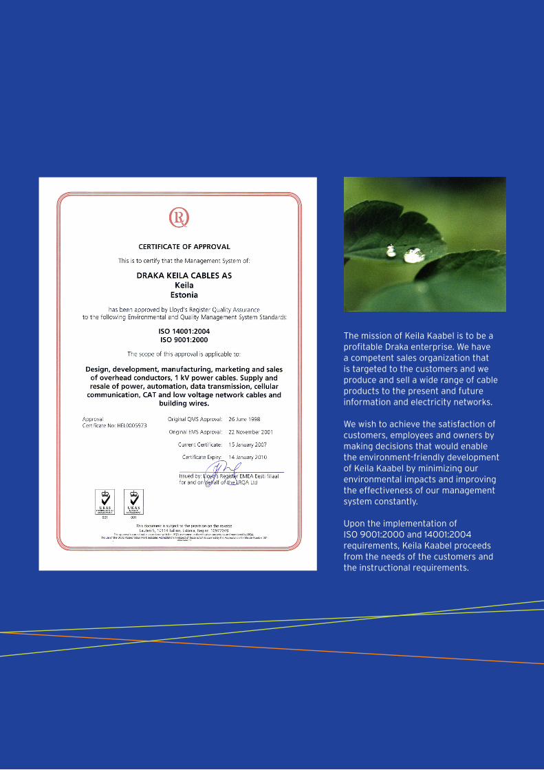
The mission of Keila Kaabel is to be a profitable Draka enterprise. We have a competent sales organization that is targeted to the customers and we produce and sell a wide range of cable products to the present and future information and electricity networks.
We wish to achieve the satisfaction of customers, employees and owners by making decisions that would enable the environment-friendly development of Keila Kaabel by minimizing our environmental impacts and improving the effectiveness of our management system constantly.
Upon the implementation of ISO 9001:2000 and 14001:2004 requirements, Keila Kaabel proceeds from the needs of the customers and the instructional requirements.

Draka | Energy & Infrastructure | Draka Keila Cables
AS Draka Keila Cables | Paldiski Road 31 | 76606 Keila | EstoniaPhone +372 674 7466 | Fax +372 674 7468
www.drakakeila.ee
Member of the DRAKA Holding Group
www.draka.com
Top Related