


Languages
Pages
Legal


D l i USB li ti i thDeveloping USB applications using the STM32 ARM Cortex-M3 microcontroller
Anis BEN ABDALLAHEmbedded World 2011Embedded World 2011

Agenda
Review of some important concepts in USB 2.0 standard
USB d i t ll i l t ti i th STM32USB device controller implementations in the STM32 microcontroller series
Building blocks of a USB device application
Overview about the STM32 USB device firmware libraryy
Overview about the USB Personal Healthcare Device Class (PHDC) and ContinuaTM ready ST stackClass (PHDC) and Continua ready ST stack
ST PC software package for USB development

Review of Important Concepts in USB 2.0 Standard

USB Speeds and bus components
USB 2.0 speedsLow speed: 1.5 Mbits/s Full speed : 12 Mbits/sFull speed : 12 Mbits/s High speed: 480 Mbits/s
USB keeps high compatibility at protocol level betweenUSB keeps high compatibility at protocol level between all supported speeds
Bus componentsBus componentsUSB host or Root hub: initiates all the transaction on the busUSB function: is a device with one or more interfaces that expose capabilities to the host (ex: mouse, keyboard,..)USB hub: allows to connect multiple devices to the USB host. It has an upstream port for communication with the host and multiple downstream ports for direct connection to devices

USB Topology
USB bus has a Tiered Star topology
At the center of each star is a hub with functions as end connections
A maximum of 127 devices can be connected in the bus
A maximum of 5 hubs can be connected in series
the maximum cable length isthe maximum cable length is 5meter
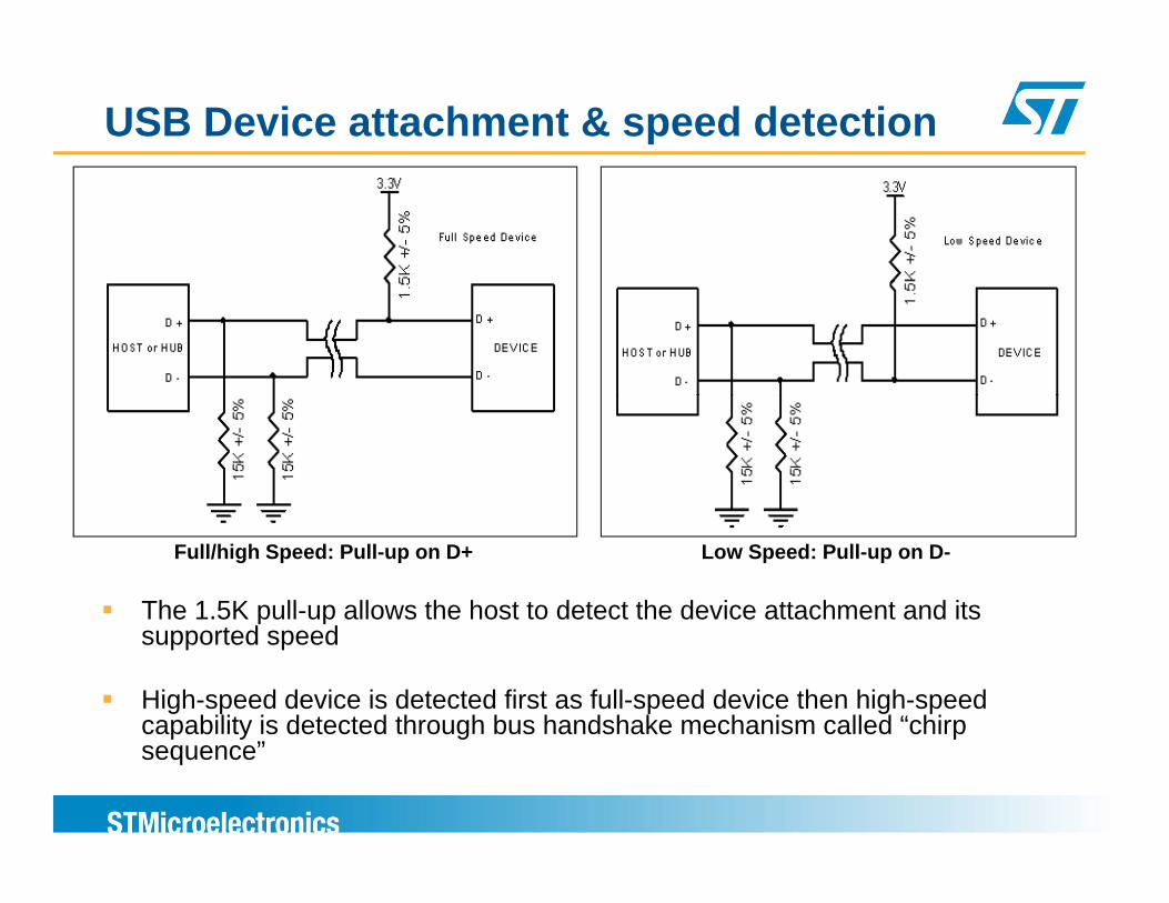
USB Device attachment & speed detection
The 1.5K pull-up allows the host to detect the device attachment and its
Full/high Speed: Pull-up on D+ Low Speed: Pull-up on D-
p psupported speed
High-speed device is detected first as full-speed device then high-speed capability is detected through bus handshake mechanism called “chirp p y g psequence”
USB Device Power
Two possible power configurationsSelf-powered: device power provided from external power-supplyB d id d f VBUS (5 )Bus-powered: power provided from VBUS (5v)
For bus-powered device, two options are possible:p , p pLow-power devices :maximum power consumption is 100mAHigh-power devices :maximum power consumption is 100mA during bus enumeration and 500mA after configurationg g
During device enumeration, the device indicates to host its power configuration (self powered/bus powered) andits power configuration (self-powered/bus-powered) and its power consumption in the device configuration descriptor

USB Suspend modeUSB device should enter in USB Suspend mode when the bus is in idle state for more than 3 ms
In suspend mode, when the device is bus powered , the current drawn from VBUS power shouldn’t exceed 2.5mA
USB h t t d i f t i i d d bUSB host prevents device from entering in suspend mode by periodically issuing Start of Frame (SOF) or Keep Alive for LS
For High-speed, SOF is sent every micro-frame: 125us +/- 65nsFor Full-speed, SOF is sent every frame: 1ms +/- 500nsp yFor Low-speed, Keep Alive (End of Packet) is sent every 1ms in absence of low-speed data
Exist from Suspend mode can beExist from Suspend mode can beInitiated from host by issuing the resume signalingInitiated from device by issuing the remote wakeup signaling

USB TransactionToken packet (SETUP, IN, OUT) always issued by the host, includes:
PID (IN: Device to host data transaction or SETUP/OUT: host to device data transaction)Target device addressTarget endpoint numberTarget endpoint numberCRC
Data packet (DATA0, DATA1, DATA2, MDATA) includes:PID: DATA0, DATA1, DATA2 or MDATA (DATA2 and MDATA are used only in HS mode)C i th d t l d f t ti t b th h t d iCarries the data payload of a transaction sent by the host or deviceDATA PID toggle used to synchronize HOST and DEVICE to avoid repeated packet transfer in case of corrupted or lost handshake CRC
H d h k k t (ACK NAK STALL NYET)Handshake packet (ACK, NAK, STALL, NYET) ACK: packet reception acknowledged (sent from host or device)NAK : packet reception not acknowledged (sent from device only)STALL: control request not supported or endpoint halted (sent from device only)NYET: device not ready to accept further packets (only for high-speed device)NYET: device not ready to accept further packets (only for high speed device)
Token packet Data packet (up to 1023 bytes) Handshake packet
PID ADDRESS ENDPOINT CRC PID DATA CRC PID

Examples of IN/OUT transactions
OUT
Host Device Host Device
DATA0ACK
OUT IN
NAK
INOUT
DATA1 ACKDATA0
NAK
OUTIN
ACK
ACK
DATA1
ACKDATA1

USB Transfer
A USB transfer is composed of one or multiple bus transactions
Four types of USB transfers are defined:Four types of USB transfers are defined:Control: used for control and device configuration requests (ex: device enumeration)Bulk: used for data transfers with no guaranteed delivery rate (ex: g y (printer, mass-storage drive,..)Interrupt: used for devices that need to be polled periodically for data transfers (ex: mouse, keyboard, joystick)Isochronous: used for data streaming applications that requires aIsochronous: used for data streaming applications, that requires a guaranteed delivery rate, but no error checking (ex: audio, video devices)
During each frame (in LS/FS) or micro-frame (in HS), the host will schedule the needed transfers with different bandwidth allocation for each transfer type

USB Control TransferUsed for standard control requests during device enumeration process or during class operation
f ( )All devices should support control transfer through endpoint 0 (bidirectional)
It is given reserved bus bandwidth for 10% for FS/LS and 20% for HS
Control transfer has 3 stagesSETUP stage: one SETUP transaction for issuing the control request (ex: Get Descriptor)Optional DATA stage IN or OUT: one or multiple data transactions p g pStatus stage: one IN or OUT transaction with a Zero Length data packet to check if control transfer request executed correctly or not.
The maximum data packet size during the optional data stage is 8 bytes for p g p g yLS and 64 bytes in FS/HS
Transfer error management done through handshake packet and data PID toggle mechanismtoggle mechanism

Example of a USB Control Transfer
Get device descriptor standard request:
SETUP stage
DATA stage IN
STATUS stage

USB Bulk Transfer
Used to transfer large amount of data without guaranteed delivery rate (sending data to printer, drive,..)
Lowest priority transfer with no reserved bus bandwidth but can occupy the full bandwidth if no other transfer on the bus
Supported only by full-speed and high-speed devices
Consist of one or more IN or OUT transactions during eachConsist of one or more IN or OUT transactions during each frame/micro-frame (unidirectional)
The max packet size is 64 bytes for FS and 512 bytes for HSThe max packet size is 64 bytes for FS and 512 bytes for HS
Transfer error management done through handshake packet and data PID toggle mechanismgg

USB Interrupt TransferInterrupt transfers are used to poll devices to determine if they have data that needs to be transferred (mouse, keyboard,..)
O fInterrupt IN or OUT data transfers are scheduled periodically within a maximum polling period negotiated during device enumeration but host is free to initiate more IN/OUT transactions if there is bandwidth available
limited reserved bandwidth for Low/Full speed devicesFor low-speed the packet max length is 8 bytes with a guaranteed maximum latency of up to 1 packet each 10 frames => 800 Bytes/sFor full-speed the packet max length is 64 bytes with a guaranteed maximum latency of up to 1 packet each frame => 62 5 KBytes/slatency of up to 1 packet each frame => 62.5 KBytes/s
High bandwidth with high-speedFor high-speed the packet max length is 1024 bytes with up to 3 packets each micro framemicro-frame
Transfer error management done through handshake packet and data PID toggle mechanism

USB Isochronous transfersUsed mainly for streaming real-time data like audio and video
Needs a guaranteed bandwidth with a constant transfer rate but there is no error checkingchecking
The requested bandwidth is negotiated between host and device during enumeration
Transfer is in one direction and can consist of one or more data OUT or INTransfer is in one direction and can consist of one or more data OUT or IN transactions with no handshake packet
In FS, the max packet length is 1023 bytes with a maximum of one packet per frameIn HS, the max packet length is 1024 bytes with a maximums of 3 packets per micro-frame
Devices that use isochronous transfer need in most of the cases to establish a synchronous connection (ex: speaker, microphone, video camera,...)
Minimal or no data buffering
The synchronization between the data source (producer) and the sink (consumer) canThe synchronization between the data source (producer) and the sink (consumer) can be achieved by
Having the source and sink clocks synchronized to the SOF packet Doing a clock adaptation either on the source using a dedicated feedback pipeline or on the sink clock based on the received data rate

Host constraints for Interrupt & Isochronous Transfers
The host may not be able to provide the requested bandwidth to device, in this case the host will try other possible configurations with lower bandwidth requirements (if provided by the device)lower bandwidth requirements (if provided by the device)
If still no bandwidth available, the host will refuse device fi ticonfiguration
Host software may have some latency for processing data and issuing transfer requests on time due to other processes taking CPU time
In order to avoid multiple SW calls for handling data to be transmitted or received, large chunks of data transfers should be scheduled

USB High-Speed mode specific features PING/NYET Protocol
For control and bulk transfers, when a high-speed device is not ready to receive further data OUT packets, it can send the NYET handshake
When the host receives the NYET handshake it shouldWhen the host receives the NYET handshake, it should send the PING packet periodically to check if device is ready or not to resume receiving data packets
When ACK is received for a PING request, the host will di d t k tresume sending data packet

USB High-Speed mode specific features SPLIT Protocol
The SPLIT protocol is used when the HS host need to communicate with a low/full speed device which is connected to a high speed hubconnected to a high-speed hub
The host will do the data transaction with the HS hub in high-speed, then the hub as a host will initiate the same transaction in low/full speed with the device
The data transaction done by the host with the HUB is preceded with the Start SPLIT (SSPLIT) token
The host will later use CSPLIT token to retrieve the device response from the HUB p

USB controllers in the STM32 microcontroller series

USB Device Controllers in STM32 series
USB device controller is present in almost all STM32 ARM Cortex-M3 series
Three hardware implementations are availableUSB 2.0 full-speed device controllerUSB 2.0 full-speed OTG dual role host/device controllerUSB 2.0 full speed OTG dual role host/device controllerUSB 2.0 high-speed OTG dual role host/device controller
Selection of the controller that can fit the application needs will ppdepend on
Needed USB transfer performanceNeeded CPU performanceAvailable Flash and RAM memory sizePresence of other needed peripherals Power consumption requirementsExternal components (BOM)External components (BOM)

USB Device Controller in STM32 series
USB 2.0 Full-speed Device Controller
USB 2.0 Full-speed Device Controller Features
Available on the following ARM Cortex-M3 platforms:STM32F102: USB access line (48 MHz MCU, up to 16KB SRAM and 128KB of FLASH )128KB of FLASH )STM32F103: Performance line (72 MHz MCU, up to 96KB SRAM and 1MB FLASH)STM32L152: Ultra-low power series (32 MHz MCU, up to 16KB SRAM and 128KB of FLASH)and 128KB of FLASH)
Main featuresUSB 2 0 full speed compliantUSB 2.0 full-speed compliantUp to 8 bi-directional endpoints (or 16 unidirectional endpoints) Embedded full-speed analog transceiverSupports all transfer modes (control bulk interrupt and isochronous)Supports all transfer modes (control, bulk, interrupt and isochronous)Dedicated SRAM area of 512 bytes as packet memory that can be shared among the needed endpointsDouble-buffering mechanism for isochronous and bulk transfersUSB Suspend/Resume with system entry/wakeup for low power mode

USB 2.0 Full-speed Device ControllerBlock Diagram
D+ D-
SIE (Serial Interface Engine)NRZI Encoding/DecodingSynchronization & Pattern RecognitionBit t ffi d H d h k l ti
D+ D
AnalogTransceiver
PLL USB IP
48 MHz
Bit-stuffing and Handshake evaluationPID & CRC generation and checkingInterrupt generation
Suspend TimerGenerate the Suspend interrupt when
SuspendTimer
ControlRegisters & Logic
InterruptRegisters & Logic
ClockRecovery
EndpointSelection
RX-TX
Control
SIE48MHzGenerate the Suspend interrupt when no SOF is detected for 3ms
Packet Buffer Memory512 bytes dedicated SRAM memoryThe Arbiter allows dual access either
PacketBuffer
I t f
g gS
EndpointRegisters
48MHz USB Clock
DomainAPB Clock
Domain
from packet buffer interface or APB interface
3 interrupt vectors (lines)Low priority interrupt for managing all endpoints
Interface Registers
InterruptMapperArbiter
PacketBuffer
RegisterMapperp
High priority interrupt: can be used for managing isochronous/double-buffered endpoints onlySuspend/Resume interrupt
MapperArbiter BufferMemory
Mapper
APB Interface APB Interface
Interrupt linesAPB busAPB_CLK
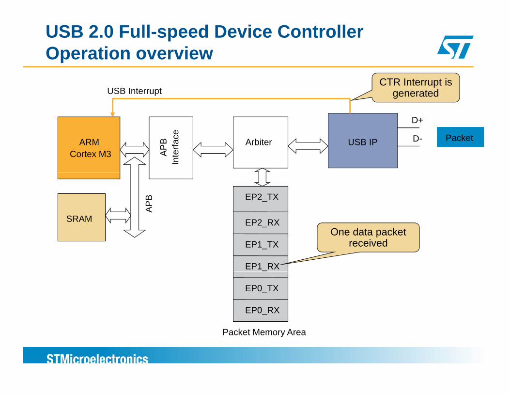
USB 2.0 Full-speed Device ControllerOperation overview
D+
USB InterruptCTR Interrupt is
generated
ARM Cortex M3 AP
B In
terfa
ce USB IP
D
D-Arbiter Packet Packet
EP2 RX
EP2_TX
SRAM
APB
EP1_RX
EP2_RX
EP1_TXOne data packet
received
EP0_RX
EP0_TX
Packet Memory Area
USB 2.0 Full-speed Device ControllerTransactional model handling
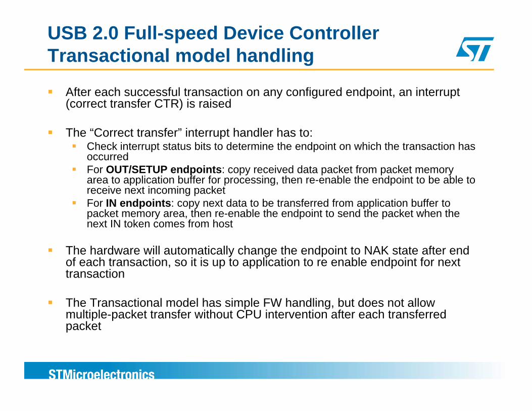
After each successful transaction on any configured endpoint, an interrupt (correct transfer CTR) is raised
“C fThe “Correct transfer” interrupt handler has to:Check interrupt status bits to determine the endpoint on which the transaction has occurredFor OUT/SETUP endpoints: copy received data packet from packet memory area to application buffer for processing then re enable the endpoint to be able toarea to application buffer for processing, then re-enable the endpoint to be able to receive next incoming packetFor IN endpoints: copy next data to be transferred from application buffer to packet memory area, then re-enable the endpoint to send the packet when the next IN token comes from host
The hardware will automatically change the endpoint to NAK state after end of each transaction, so it is up to application to re enable endpoint for next transaction
The Transactional model has simple FW handling, but does not allow multiple-packet transfer without CPU intervention after each transferred packet

USB 2.0 Full-speed Device ControllerEndpoint Configuration/Enabling
Before start of any transfer on one endpoint, the following configuration should be done:
Endpoint address (only lower four bits)Endpoint transfer type (control, bulk, interrupt or isochronous)Endpoint TX or RX packet start address location in the packet memory areaFor OUT/SETUP endpoints the max receive packet size should beFor OUT/SETUP endpoints the max receive packet size should be configured
After the configuration, endpoint can be enabled for a transferIN endpoint:IN endpoint:
Data can be copied from application buffer to endpoint PMA bufferthe TX transfer count should be updated (the maximum is one max packet size)Endpoint status should be changed to “ACK” to allow data transfer when INEndpoint status should be changed to ACK to allow data transfer when IN token arrives
OUT/SETUP endpoint:Endpoint status should be changed to “ACK” to allow OUT/SETUP data packet reception on endpointp p p
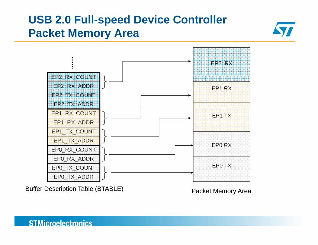
USB 2.0 Full-speed Device ControllerPacket Memory Area
EP2 RX COUNT
EP2_RX
EP2_TX_ADDREP2_TX_COUNTEP2_RX_ADDR
EP2_RX_COUNT
EP1 RX
EP1_TX_COUNTEP1_RX_ADDR
EP1_RX_COUNT_ _
EP1 TX
EP0 TX COUNTEP0_RX_ADDR
EP0_RX_COUNTEP1_TX_ADDR
EP0 TX
EP0 RX
EP0_TX_ADDREP0_TX_COUNT
Packet Memory AreaBuffer Description Table (BTABLE)

USB 2.0 Full-speed Device ControllerDouble-Buffering mechanism
Double buffering is used to improve the transfer performance for isochronous and bulk endpoints (in one direction only)
Consists of using two buffers in PMA (buffer0 and buffer1) at any time CPU shouldConsists of using two buffers in PMA (buffer0 and buffer1), at any time CPU should be accessing one buffer (for R/W) while USB IP is accessing the other buffer
USB swapping between buffer0 and buffer1 is done by hardware
In double-buffered bulk transfer, If application (CPU) is too slow to give its buffer to USB, then NAK will be sent to host
CPUEP1 BUFF1EP1 BUFF1
USB CPUEP1 BUFF0EP1 BUFF0
PMA

USB 2.0 Full-speed Device ControllerPacket Memory Area with double-buffering
EP1 TX Buffer 0
EP1 TX Buffer 1
EP1_TX_COUNT_1
EP1_TX_ADDR_0EP1_TX_COUNT_0EP1_TX_ADDR_1
EP0 RX
EP1 TX Buffer 0_ _ _
EP0 TX ADDREP0_TX_COUNTEP0_RX_ADDR
EP0_RX_COUNT
EP0 TX
0
EP0_TX_ADDR
Packet Memory AreaBuffer Description Table (BTABLE)

USB 2.0 Full-speed Device ControllerSuspend/Resume Interrupt
When no SOF is detected for 3 ms, a suspend interrupt is generated
In the interrupt handler of the suspend interrupt if bus poweredIn the interrupt handler of the suspend interrupt, if bus powered device, the MCU should enter in low power mode in order to lower its power consumption
In order to achieve the best low power consumption, the STM32 can enter in STOP mode (all peripherals and CPU clocks OFF)
A host resume/reset signaling detection can wakeup the MCU from STOP mode
The device can also initiate a bus resume or “remote wakeup” using external interrupt that can wakeup MCU from STOP mode

USB Device Controller in STM32 series
USB 2.0 Full-Speed OTG Host/Device Controller

USB 2.0 Full-Speed OTG Host/Device Controller Features
Available on the STM32 connectivity lineSTM32F105/7 : 72 MHz cortex M3 MCU with up to 64KB SRAM and 256KB FLASHand 256KB FLASH
Main featuresUSB 2.0 Full-speed dual role Host/Device with OTG modeUSB 2.0 Full speed dual role Host/Device with OTG mode supportCan be configured as host-only or device-only controllerIntegrated Full-speed PHY with OTG mode supportDedicated packet memory of 1.25 Kbytes with advanced FIFO management and dynamic memory allocationDevice mode features
1 bidirectional control endpoint01 bidirectional control endpoint0Up to 3 IN and 3 OUT endpoints configurable to support Bulk, Interrupt or isochronous transfer1 shared FIFO for all OUT and control endpointsUp to 3 dedicated TxFIFOs for IN and control endpointsUp to 3 dedicated TxFIFOs for IN and control endpoints

USB 2.0 Full-Speed OTG Host/Device Controller FIFO operation
ARM Cortex M3CPU
AHB busOTG_FS interrupt
USB pushes received packets into RXFIFO
Shared RxFIFOPUSHPOP
packets into RXFIFO while CPU pops packets
D+
EP0 TxFIFOCPU pushes packets into TXFIFO while USB
pops packetsFull-SpeedTransceiver
D+
D-USBMAC
AHBInterface
EP1 TxFIFOPUSH POP
pops packets
EP2 TxFIFO

USB 2.0 Full-Speed OTG Host/Device Controller FIFO Configuration & Transfer initialization
FIFOs configurationThe size of TxFIFOs and the shared RxFIFO can be configured as needed by the application in a shared memory space ofas needed by the application in a shared memory space of 1.25KBytesDynamic reconfiguration of the FIFOs sizes is possible
OUT/SETUP transfer initializationSoftware should configure the transfer sizeEnable the endpoint for packet receptionWait packets to be received
IN transfer initializationSoftware should configure the transfer sizeEnable the endpoint Start writing data to dedicated endpoint TxFIFO

USB 2.0 Full-Speed OTG Host/Device Controller Interrupt handling
Three important interrupts are used during transfertransfer
TxFIFOn empty interrupt: occurs when TxFIFO for endpoint n is empty or half empty, used to inform
li ti th t it it d t t T FIFOapplication that it can write more data to TxFIFOShared RxFIFO Queue level interrupt: raised when there is at least one received data packet inside thethere is at least one received data packet inside the shared RXFIFOCorrect Transfer Interrupt: occurs when the full programmed transfer is finished on one endpoint

USB Device Controller in STM32 series
USB 2.0 High-Speed OTG Host/Device Controller
USB 2.0 High-Speed OTG Host/Device Controller Features
Available on the new STM32F2x Cortex-M3 ARM platformUp to 120MHz MCUUp to 128KBytes of SRAM and up to 1 Mbytes of FLASHp y p yUp to two USB controllers
One Full-Speed USB dual role host/device OTG controllerOne High-Speed USB dual role host/device OTG controller
Device featuresHigh-speed/Full-speed Device support1 bidirectional control endpoint0U t 5 IN d 5 OUT d i t fi bl t t B lk I t tUp to 5 IN and 5 OUT endpoints configurable to support Bulk, Interrupt or isochronous transferDedicated DMA with access to internal SRAM or external memory busDedicated packet memory of 4 Kbytes with advanced FIFO management
d d i ll tiand dynamic memory allocationInternal analog transceiver for Full-Speed modeNeeds connection to external transceiver for High-speed mode through ULPI bus

USB 2.0 High-Speed OTG Host/Device Controller FIFO operation
SRAM
ARM Cortex M3CPU
AHB bus OTG_FS interrupt
USB pushes received packets into RXFIFO
AHB MasterInterface
AHB SlaveInterface
Shared RxFIFOPUSHPOP
packets into RXFIFO while DMA pops packets
InterfaceInterface
ULPIHigh-SpeedTransceiver
D+
D-USBMACDMA
EP0 TxFIFODMA pushes packets into TXFIFO while USB
pops packetsAHBSlave
EP1 TxFIFOPUSH POP
p p pSlaveInterface

USB 2.0 High-Speed OTG Host/Device ControllerDMA operation
DMA allows to manage a full transfer without CPU intervention after each transaction
CPU is informed of end of transfer using the Correct transfer interrupt
A custom threshold FIFO level can be defined to trigger data transfer
Transmit threshold TxFIFO trigger level: free space in TxFIFO than can trigger an transfer from memory to FIFOReceive threshold RxFIFO trigger level: a minimum receive data level in receive FIFO that can trigger a transfer to memory

Summary Comparison Table
Controller USB Full-Speed Device controller
USB OTG Full-speed dual role host/device
USB OTG High-speed dual role host/device
S t d F ll d l iSupported speeds Low/Full speed Full speed only in
device mode High/Full speed
Number of-1 bidirectional control -1 bidirectional control
Number of endpoints 8 bidirectional
control- 3 IN- 3 OUT
- 5 IN- 5 OUT
CPU speed Up to 72MHz Up to 72MHz Up to 120 MHzCPU speed Up to 72MHz Up to 72MHz Up to 120 MHz
FIFO support NO YES YES
Packet Memory 512 Bytes 1.25 KBytes 4 KBytes
DMA support NO NO YES
PHY Internal Full-Speed Internal Full-Speed-Internal Full-Speed-External High-speed p p g p(through ULPI bus)

Building Blocks of a USB Device Application

Building Blocks of a USB Application
Application (mouse, keyboard, Device
USB Standard USB Class Layer
pp ( yspeaker,…) Descriptors
Control Requests(USB spec chapter 9)
(HID, Mass-Storage, CDC, vendor class…)
Control TransferEndpoints
USB Low Level Driver
Control Transfermanagement
Endpoints R/W access
USB controller Hardware

USB DescriptorsDevice
descriptor
ConfigurationConfigurationdescriptor
Configurationdescriptor
Interface InterfaceInterfacedescriptor
descriptor
Endpoint
descriptor
Endpoint EndpointEndpointdescriptor
descriptor
Endpointdescriptor
Device Descriptor: includes information of the device (PID, VID, Class) and the number of supported configurations
pdescriptor
pdescriptor
pdescriptor
descriptor descriptor
Configuration Descriptor: Includes the power configuration information, the number of supported interfaces in this configurationConfigurations are mutually exclusive
Interface Descriptor: provides information about function or feature that device implements (class, subclass ) also it indicates the number of endpoint it supportssubclass,…) also it indicates the number of endpoint it supportsEndpoint Descriptor: provides information about the endpoint (address, type, max packet size)

Device DescriptorOffset Field Size Description
0 bLength 1 Descriptor size in bytes (12h)
1 bDescriptor Type 1 01h1 bDescriptor Type 1 01h
2 bcdUSB 2 USB spec release number (BCD) (0200h)
4 bDeviceClass 1 Class code (00h when interface desc defines class)
5 bDeviceSubclass 1 Subclass code
6 bDeviceProtocol 1 Protocol code
7 bMaxPacketSize0 1 Maximum endpoint size for endpoint 0 (64)
8 idVendor 2 Vendor ID
10 idProduct 2 Product ID
12 bcdDevice 2 Device release number (BCD)
14 iManufacturer 1 Index of string descriptor for the manufacturer
15 iProduct 1 Index of string descriptor for the product
16 iSerialNumber 1 Index of string descriptor for the serial number
17 bNumConfigurations 1 Number of possible configuration

Configuration DescriptorOffset Field Size (byte) Description
0 bLength 1 Descriptor size in bytes (09h)
1 bDescriptorType 1 02h
2 wTotalLength 2 The number of bytes in the configuration descriptor and all of its subordinate description
4 bN I t f 1 N b f i t f i th fi ti4 bNumInterfaces 1 Number of interfaces in the configuration
5 bConfiguration Value 1 Identification for the configuration
6 iConfiguration 1 Index for string descriptor for the configuration
7 bmAttributes 1 Self or bus powered / remote wakeup setting
8 bMaxPower 1 Bus power required in units of 2mA

Interface descriptorOffset Field Size (byte) Description
0 bLength 1 Descriptor size in bytes (09h)
1 bD i t T 1 04h1 bDescriptorType 1 04h
2 bInterfaceNumber 1 Number identifying the interface
3 bAlternateSetting 1 Number that identifies an Alternate interface for bInterfaceNumber
4 bNumEndpoints 1 Number of endpoints supported by the interface (without counting endpoint zero)
5 bInterfaceClass 1 Class code (ex HID = 03h)5 bInterfaceClass 1 Class code (ex HID 03h)
6 bInterfaceSubclass 1 Subclass code (ex Boot Interface Subclass = 01h)
7 bInterfaceProtocol 1 Protocol code (ex Mouse = 02h)
8 iI t f 1 I d f t i d i t f th i t f8 iInterface 1 Index for string descriptor for the interface

Endpoint DescriptorOffset Field Size (byte) Description
0 bLength 1 Descriptor size in bytes (07h)
1 bDescriptorType 1 05h
2 bEndpointAddress 1 Endpoint number and direction
3 bmAttributes 1 Transfer Type (bulk, interrupt, isochronous)
4 wMaxPacketSize 2 Maximum packet size supported
6 bInterval 1 Polling time for interrupt or isochronous EP

Class LayerA class specifies the operation of group of USB devices that have similar functionalities, ex:
Audio class (speaker, microphone)Communication device class (virtual COM-port, modems, Ethernet adapters,…)Human Interface Device class (mouse, keyboard, joystick,…)
Defining a USB class allows to have unique host driver for all devices belonging to the class
A USB l d fiA USB class definesRequired or optional endpointsNeeded InterfacesClass-specific descriptorsp pRequired values for fields in the standard descriptorsClass Control requestsFormat of data to be transferred and optionally the protocol layer for data transfer (ex Bulk-only transfer for Mass-Storage class)transfer (ex Bulk-only transfer for Mass-Storage class)
Human Interface Device (HID)HID class is mainly intended for devices that have interaction with human inputs (moving a joystick, a mouse, pressing a keyboard…) but can be used for other application
Supported natively by MS Windows operating system
HID needs one IN interrupt endpoint to transfer data, the host will poll the IN p p pendpoint periodically to check if device has data to transfer
Transferred data is formatted in fixed structure called HID Report
HID defines six specific control requestsGet/Set Report: allows to get/send report to deviceSet/Get Idle: allows to get/set the idle rate Set/Get Protocol: allows to get/set used protocol (boot or report protocol)Set/Get Protocol: allows to get/set used protocol (boot or report protocol)
Two class specific descriptors are definedHID class descriptor HID Report descriptorHID Report descriptor

USB Control Transfer ManagementShould implement a state machine for managing the three stages of a control transfer on endpoint0
SETUP stageO ti l D t IN OUT tOptional Data IN or OUT stageHandshake stage
During the SETUP stage, the received request can beStandard USB Request as defined in USB spec Chapter 9Standard Class USB request (HID, CDC,…)Vendor Class USB request
In case a request is not supported, the control endpoint should send a STALL handshake packet to host
A control request can targetA control request can targetDeviceInterfaceEndpoint
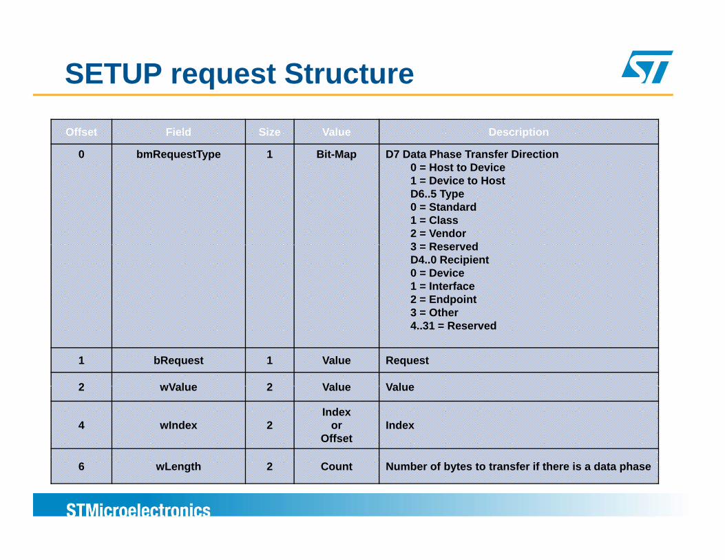
SETUP request Structure
Offset Field Size Value Description
0 bmRequestType 1 Bit-Map D7 Data Phase Transfer Direction0 = Host to Device1 = Device to HostD6..5 Type0 = Standard1 = Class2 = Vendor3 = Reserved3 = ReservedD4..0 Recipient0 = Device1 = Interface2 = Endpoint3 = Other3 Other4..31 = Reserved
1 bRequest 1 Value Request
2 wValue 2 Value Value2 wValue 2 Value Value
4 wIndex 2Index
or Offset
Index
6 wLength 2 Count Number of bytes to transfer if there is a data phase

Standard USB Control Requests
Control requests are defined in chapter 9 of the USB specification
Used mainly during the enumeration phase by the host to get needed descriptors information about the device and to select the needed configurationconfiguration
Some standard requests (Get Feature/ SetSome standard requests (Get Feature/ Set Feature, Get Status) may be used as a class requests to get/set class specific features

Standard USB control RequestsbRequest Target Description
GET_STATUS (0x00)
Device orInterface orEndpoint
-Device: allows to get the device power settings-Endpoint: allows to check STALL status of endpoint
p
CLEAR_FEATURE (0x01)
Device orInterface orEndpoint
-Device: allows to clear Device remote wakeup feature-Endpoint: allows to clear STALL status for an endpoint
SET FEATURE Device orI t f
-Device: Sets Remote wakeup featureE d i t S t STALL diti d i tSET_FEATURE
(0x03) Interface orEndpoint
-Endpoint: Sets STALL condition on endpoint
SET_ADDRESS (0x05) Device
Sets device address
GET DESCRIPTOR Gets a Descriptor (Device Configuration String)GET_DESCRIPTOR(0x06) Device
Gets a Descriptor (Device, Configuration, String)
GET_CONFIGURATION (0x08) Device
Gets the value of current configuration
SET CONFIGURATION Sets the config ration to seSET_CONFIGURATION (0x09) Device
Sets the configuration to use
GET_INTERFACE(0x0A) Interface
For interfaces that have alternate interfaces, the host requests the current alternate interface
SET INTERFACE F i t f th t h lt t i t f th h tSET_INTERFACE(0x0B) Interface
For interfaces that have alternate interfaces, the host requests to set a particular alternate interface

USB Low Level Driver
Functions/Macros that do direct access to USB block registers forDevice global initializations (ex: device address, speed,..)Endpoints initialization (ex: address transfer type )Endpoints initialization (ex: address, transfer type, ...)Transfer initializationPacket memory area or FIFO access
Manage the USB interrupts with callbacks to application layersGlobal device interrupts (USB Reset, USB suspend,..)Endpoints transfer related interrupts (correct transfer interrupt, TxFIFOn empty,…)
Power management functions during Suspend/resumeE t i l d d i d dEntry in low-power mode during suspend modeRemote wakeup management

STM32 USB device firmware library

USB Device Developer KitAllows to easily get started with USB device development on STM32 platforms
The kit provides all the needs firmware blocks includingLow level USB driversFirmware for handling the standard control requests (chapter 9)USB class la er implementation ith demos r nning on e alboards forUSB class layer implementation with demos running on evalboards for
Mass-StorageHIDCDC Virtual COM port A di ( k i h )Audio (speaker, microphone)Device Firmware Upgrade
The Library allows easy development of Custom vendor classy y p
All the class implementations are validated using the USB Command Verifier tool provided by the USB-IF

Folder Organization of the STM32 USB Developer Kit
LibrariesCMSIS : Cortex Microcontroller Software Interface Standard files (startup files, NVIC, clock config)STM32_USB-FS-Device_Driver: Includes the USB low level driver + firmware for handling control transfer and standard control requestsSTM3210x_StdPeriph_Driver: low level drivers f t d d i h l (ti l k )for standard peripherals (timer, clocks, ..)
ProjectImplementation for the various class demospEach demo includes workspaces for different third-party toolsets (IAR, KEIL, RIDE, HITEX, Attolic)
UtilitiesEvalboard utilities (buttons, LCD, SD card access,..)

STM32_USB-FS-Device_Driver Low Level Driver
The folder includes low level drivers for:The USB Full-speed device controllerThe OTG Full-speed controller (only for device mode)
Source files for the OTG Full-speed device controller:
file Description
otg_fs_int.c All USB Interrupt handling with callbacks to application layer
otg_fs_pcd.c High level functions for Endpoint access (Read/Write, Open/Close,..)
otg_fs_cal.c Core access layer (function doing register access for global device configuration, endpoint initializations, transfer initializations, FIFOs R/W)
otg_fs_dev.c Wrapper for device/endpoints high level access, implemented for compatibility reason with the USB full-speed controllercompatibility reason with the USB full speed controller
Usb_sil.c Serial Interface Layer (SIL) :Wrapper for endpoint R/W access implemented for compatibility reason with the USB full-speed controller

STM32_USB-FS-Device_Driver Control transfer & Library initialization
All the handling of control transfer and the standard USB requests is done in file usb_core.c
The implementation allows the handling of the standard control requests and the dispatching to class layer whencontrol requests and the dispatching to class layer when receiving a class control request
File usb_init.c includes one function USB_Init() that should be called to initialize the library structures and to d d d d i i iti li ti ( t l fi tido needed device initialization (control configuration, memory allocation,…)

Class Layer Implementation
The various USB classes implementations are found in “Project” folder
For each class, the class specific control requests are implemented in file usb_prop.c
Non-control endpoints correct transfer interrupt handling is done in file usb_endp.c
The USB descriptors for the device are implemented in file usb_desc.c
Device power management is implemented in file usb_pwr.c

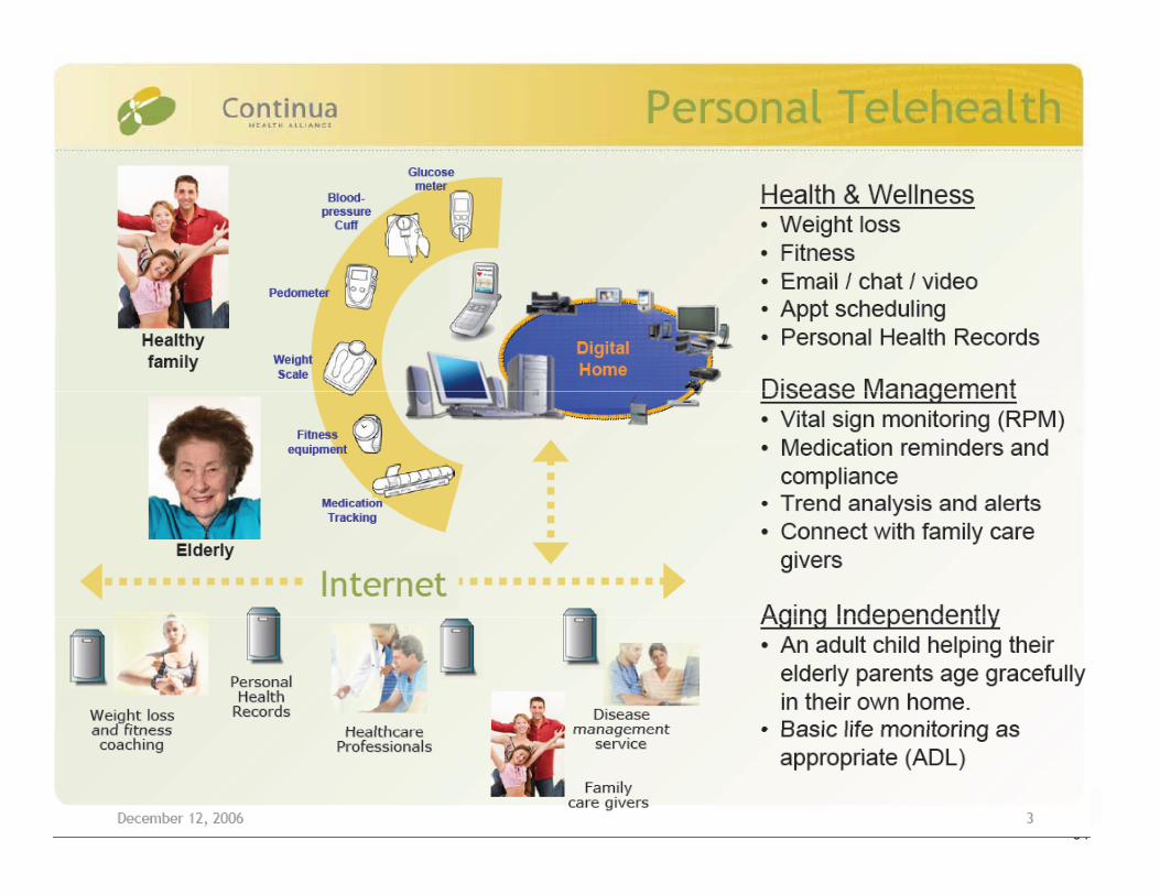
Overview about PHDC class and Continua Stack

Continua Health AllianceThe Continua Health Alliance is an open industry consortium with more than 200 member companies around the worldaround the worldTheir Mission is to establish an eco-system of inter-operable personal health systems in the healthcare sector.
ST is a contributing memberST is a contributing memberST is allowed to use the Continua Logo
After certification the logo can be used on products.
63
64

65

ST Healthcare Library features
PCPulse
O i t
Thermometer
PC
PersonalHealth System
Weight
Oximeter
Pulse /Blood Pressure
11073-10404 = Pulse Oximeter11073-10406 = Pulse / Heart Rate11073-10407 = Blood Pressure11073-10408 = Thermometer11073-10415 = Weighing Scalede
pend
ent
Cell PhoneWeight
Scale
Cardiovascular
GlucoseMeter
11073 10415 Weighing Scale11073-10417 = Glucose 11073-10441 = Cardiovascular Fitness Monitor11073-10442 = Strength Fitness Equipment11073-10471 = Independent Living Activity11073-10472 = Medication MonitorTran
spor
t Ind
Set Top Box
Aggregator
Independent Living Activity
and Strength Fitness Monitor
Medication
11073-20601 = Base Framework Protocol
AggregatorMedicationAdherence
Personal Health DeviceClass Specification

Thermometer Demo based on latest CESL

Healthcare Firmware stack (1/2)
Healthcare Application
IEEE 11073-20601 Layer10408 – Thermometer
10417 – Glucose meter 10417 – Glucose meter Other device specialization
STM32L USB
USB PHDC Class Mass Storage (*) DFU (*)
STM32L USB
(*) Optional classes not linked to Medical

Healthcare Firmware stack (3/3)Main.c/h
(Thermo.c/h, Gluco.c/h, …)User Application
Service Model LayerServLayer.c/h
Transmission Template &Object service handlers
Dev_Spec_104xx.c/h
State MachineCom_Model.c/h
Transport abstraction layertil.c/h
USB TransportUSB Desc USB endp USB propUSB istrUSB_Desc USB_endp USB_propUSB_istr
69

ST offer for PC software USB

USB Offer with STM32 ( F1, L & F2) Free VID/PID Sub-licensing
Service for customers
DFU Driver Certified
Free Drivers Resell at WHQL
Windows Software Kit
Custom/Bulk Drivers
Feat
ure
s
Windows Host Driver Kit:
Certified Driver 3.0.0 , XP Vista Windows7 ( x86 & x64)
DFuSe ( Demo + Sources)
USB Host library
V1.0.0
CDC Driver Certified
WHQL Qualified
erfo
rman
ce &
F USB Host librarySTM32F105/7
Mass storage,HID (mouse & Keyboard)
Healthcare
Pe
USB PHDC Class & ContinuaSTM32L15x
Thermometer, Glucose agents
USB Developer KitDevice3.2.x
STM32F102/3DFU, Joystick, Custom HID, Mass-storage,
Audio speaker Audio Streaming
USB Developer KitDevice3.3.x
STM32F102/3 & STM32LDFU, Joystick, Custom HID, Mass-storage, Audio
speaker, Virtual com Port
71
Audio speaker, Audio Streaming,Virtual com Port
speaker, Virtual com Port
2011 Jan 2012

New PC Windows Driver (1/2)D i tiDescription :
• USB driver for Microsoft operating systems.• Designed to work with USB DFU and all specific USB classes• Allow access to the Control, Interrupt and Bulk pipes and is an
alternative to WinUSB driver without limitations.
• WHQL Certified and in production• WHQL Certified and in production • Used for STMicroelectronics USB Bootloader ( DFU)• At many customers since 2008.
• Full documented API and Reference examples with Visual C++ (6, 2005, 2008 and 2010 : x86 and x64)
A li tiApplications usage:• Device Firmware Upgrade STMicroelectronics Extension (DfuSe)• Vendor Class involving Bulk/Interrupts Pipes
A l t th ith I h Pi
72
• Any classes, except those with Isochronous Pipes.

New PC Windows Driver ( 2/2)
• Compatible Operating SystemsMS Windows 98SEMS Windows 2000MS Windows 2000MS Windows XP (x86 & x64)MS Windows Vista (x86 & x64)MS Windows Seven (x86 & x64)
• WHQL Certification Added Value to our customers
Providing quality end-to-end experience of customersRetailers expect the logo on devices & concentrate on own businessConsumers & customers look for logo-qualified products
On-line Windows Update by clicking the Update Driver button in Device Manager
73

Microsoft Logo Certification
74

New Service for STM32 USB small customersDescription :
USB “PID” and VID (0x0483) from STMicroelectronics Sub-licensing
Program Process Receive Requests from our Customers thru sales offices with customer details:
1) COMPANY NAME AUTHORZING USE TO : 2) Contact Name /Address and E-mail address:3) Name/Sales type of the ST Microcontroller product name :4) Name of USB end product : { if possible USB device string Product}4) Name of USB end-product : { if possible USB device string Product}
PID Booked in an internal ST Database
Final Step :Final Step :ST will send the approval list to USB-IFApproval by USB-IFPID sent to the customer with a “letter form Agreement”
75
PID sent to the customer with a letter form Agreement

End-to-end experience of customers
76
Top Related