


Languages
Pages
Legal

Faculty of Science, Engineering and Computing
School of Mechanical and Automotive Engineering
MEng (Hons) Degree in Mechanical Engineering
Module Code: ME6014
Name: Damien Omar Mason
KU Number: K1110597
Project Title: Study of sprinkler spray characteristics in
domestic premises
Date: 22nd April 2016
Supervisor: Dr. Siaka Dembele
WARRANTY STATEMENT
This is a student project. Therefore, neither the student nor Kingston University
makes any warranty, express or implied, as to the accuracy of the data nor
conclusion of the work performed in the project and will not be held responsible
for any consequences arising out of any inaccuracies or omissions therein.
ii
Acknowledgements
I would like to thank Kingston University for giving me the opportunity to study
a MEng in Mechanical Engineering.
I would like to thank my supervisor, Dr. Siaka Dembele, for his continued
support and guidance throughout my project. He ensured that I had a thorough
understanding of the requirements of the project and allowed me to expand my
knowledge on fires, fire suppression and fire sprinklers.
I would like to thank my mother, father and little brother for their support.
I would like to thank my friend Hugh Jones, who has been a great classmate ever
since we met in foundation year. We have a great friendship and have always
supported each other; he has made my university experience very enjoyable.
Finally, I would like to thank my partner Kalifa Coleman-‐Best who has
continually supported me through out my entire degree, has always encouraged
me to be the best I can be and thrive in Engineering. I would not have got this
far without her being by my side.
iii
Abstract On completion of this dissertation, research was carried out on the classification
of fires, types of fire sprinkler systems, fire statistics in United Kingdom and
characteristics of fire sprinklers. This research is important as it helped to
determine what are the key characteristics of a fire sprinkler, how those
characteristics affected the fire extinguishing process and demonstrated the
importance of their implementation in domestic premises. This research was
completed with both the analysis of research papers and the use of fire statistics
published by the UK government.
Once the optimum characteristics were determined, a real life scenario was
created using the Fire Dynamic Simulator software. Simulations were then
carried out and the results were analyzed; the Fire Dynamic Software was used
as it provides detailed analyses of fire behaviour.
The research indicated that the optimum characteristics were small-‐scale
droplet sizes with low to medium velocities and flow rates. With these
characteristics a variety of fires could be extinguished in seconds, which then
prevent fire growth and fire spread. These results are very important as they
demonstrate and reiterate the effectiveness of fire sprinklers in domestic
premises, the implementation of fire sprinklers in domestic premises can save
hundreds of lives on a yearly basis
iv
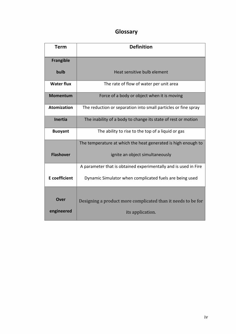
Glossary
Term Definition
Frangible
bulb Heat sensitive bulb element
Water flux The rate of flow of water per unit area
Momentum Force of a body or object when it is moving
Atomization The reduction or separation into small particles or fine spray
Inertia The inability of a body to change its state of rest or motion
Buoyant The ability to rise to the top of a liquid or gas
Flashover
The temperature at which the heat generated is high enough to
ignite an object simultaneously
E coefficient
A parameter that is obtained experimentally and is used in Fire
Dynamic Simulator when complicated fuels are being used
Over
engineered
Designing a product more complicated than it needs to be for
its application.
v
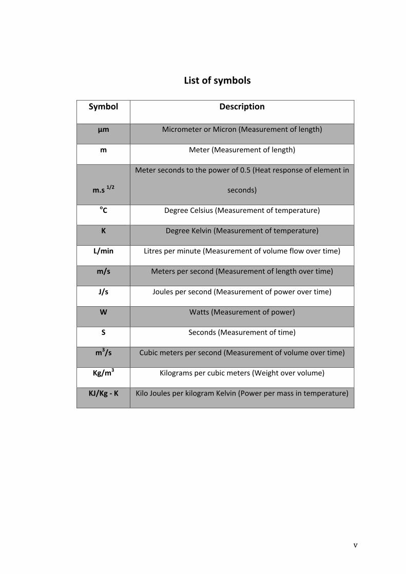
List of symbols
Symbol Description
μm Micrometer or Micron (Measurement of length)
m Meter (Measurement of length)
m.s 1/2
Meter seconds to the power of 0.5 (Heat response of element in
seconds)
oC Degree Celsius (Measurement of temperature)
K Degree Kelvin (Measurement of temperature)
L/min Litres per minute (Measurement of volume flow over time)
m/s Meters per second (Measurement of length over time)
J/s Joules per second (Measurement of power over time)
W Watts (Measurement of power)
S Seconds (Measurement of time)
m3/s Cubic meters per second (Measurement of volume over time)
Kg/m3 Kilograms per cubic meters (Weight over volume)
KJ/Kg -‐ K Kilo Joules per kilogram Kelvin (Power per mass in temperature)

vi
List of figures
Figure 1 Modern fire sprinkler head, (Dr. Jhun, 2015) ..................................................... 3
Figure 2 Henry. S. Parmelee, Automatic fire extinguisher, (Woodford, C. 2014) .. 4
Figure 3 Fire structure and regions, (2015) .......................................................................... 8
Figure 4 Differences in surface area, (2007-‐2009) .......................................................... 10
Figure 5 Spectrum of droplet diameters, (G. Grant et al. 2000) ................................. 16
Figure 6 Water flux, (2015) ....................................................................................................... 18
Figure 7 Sprinkler spray shapes, (Sheppard, 2002) ........................................................ 19
Figure 8 Sidewall sprinkler head, (Archtoolbox, 2016) ................................................ 19
Figure 9 Outer spray angle, (Rein, 2008) ............................................................................. 20
Figure 10 Process of atomization, (Marshall, 2004) ....................................................... 20
Figure 11 Starting FDS using command prompt, (2016) .............................................. 22
Figure 12 FDS input file for burning couch, (2016) ........................................................ 24
Figure 13 Smokeview visual of burning couch & temperature slice file, (2016) 25
Figure 14 Smokeview visual of fire suppression using a fire sprinkler, (2016) . 26
Figure 15 Typical heat releases vs. time in t2-‐fire characterization, (Kim, 2000)
...................................................................................................................................................... 30
Figure 16 International Sprinkler Sensitivity Ranges, Response Time Index
(RTI) versus Conductivity (C). For SI units: 1ft = 0.305m, (Madrzykowski,
2002) .......................................................................................................................................... 32
Figure 17 Distance travelled when droplets achieve 95% of terminal velocity
(m), (Sheppard, 2002) ........................................................................................................ 38
Figure 18 Simulation domain, (2016) ................................................................................... 52
Figure 19 Simulation #5 -‐ Simulation after 33.3 seconds, (2016) ............................ 53
vii
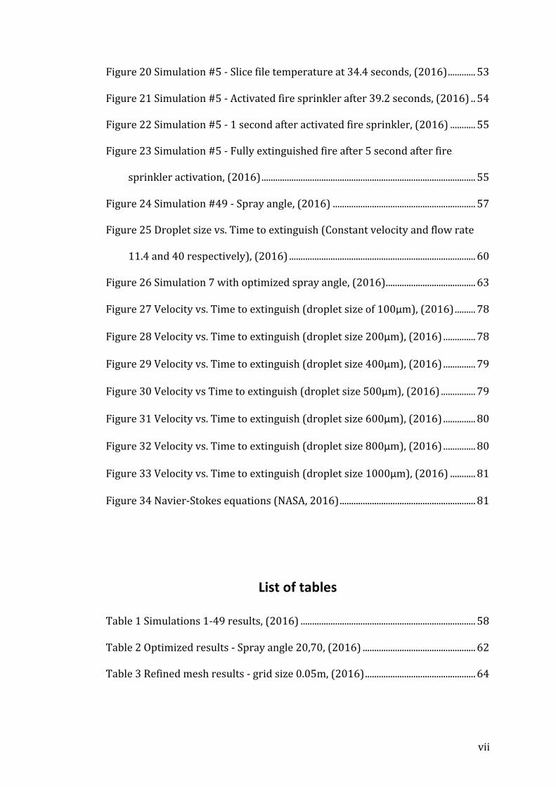
Figure 20 Simulation #5 -‐ Slice file temperature at 34.4 seconds, (2016) ............ 53
Figure 21 Simulation #5 -‐ Activated fire sprinkler after 39.2 seconds, (2016) .. 54
Figure 22 Simulation #5 -‐ 1 second after activated fire sprinkler, (2016) ........... 55
Figure 23 Simulation #5 -‐ Fully extinguished fire after 5 second after fire
sprinkler activation, (2016) ............................................................................................. 55
Figure 24 Simulation #49 -‐ Spray angle, (2016) .............................................................. 57
Figure 25 Droplet size vs. Time to extinguish (Constant velocity and flow rate
11.4 and 40 respectively), (2016) ................................................................................. 60
Figure 26 Simulation 7 with optimized spray angle, (2016) ....................................... 63
Figure 27 Velocity vs. Time to extinguish (droplet size of 100μm), (2016) ......... 78
Figure 28 Velocity vs. Time to extinguish (droplet size 200μm), (2016) .............. 78
Figure 29 Velocity vs. Time to extinguish (droplet size 400μm), (2016) .............. 79
Figure 30 Velocity vs Time to extinguish (droplet size 500μm), (2016) ............... 79
Figure 31 Velocity vs. Time to extinguish (droplet size 600μm), (2016) .............. 80
Figure 32 Velocity vs. Time to extinguish (droplet size 800μm), (2016) .............. 80
Figure 33 Velocity vs. Time to extinguish (droplet size 1000μm), (2016) ........... 81
Figure 34 Navier-‐Stokes equations (NASA, 2016) ........................................................... 81
List of tables
Table 1 Simulations 1-‐49 results, (2016) ............................................................................ 58
Table 2 Optimized results -‐ Spray angle 20,70, (2016) ................................................. 62
Table 3 Refined mesh results -‐ grid size 0.05m, (2016) ................................................ 64
viii
Abbreviations
• NIST – National Institute of Standards and Technology
• USFA – U.S Fire Administration
• BFRS – Bedfordshire Fire and Rescue Service
• HRR – Heat release rate
• RTI – Response time index
• FDS – Fire Dynamic Simulator
• SMV – SmokeView
• ADD – Actual density delivered
ix
Table of Contents
Acknowledgements ......................................................................................................... ii
Abstract ............................................................................................................................. iii
Glossary .............................................................................................................................. iv
Over engineered .............................................................................................................. iv
List of symbols ................................................................................................................... v
List of figures .................................................................................................................... vi
List of tables .................................................................................................................... vii
Abbreviations ................................................................................................................ viii
1.0 Introduction ................................................................................................................ 1
1.1 Background .......................................................................................................................... 3
1.2 Aims of study ....................................................................................................................... 5
1.3 Deliverables ......................................................................................................................... 5
2.0 Fires and Fire sprinklers ........................................................................................ 6
2.1 Fires ........................................................................................................................................ 6
2.2 Fire Sprinklers ................................................................................................................. 11
2.3 Fire suppression method using water ..................................................................... 13
2.4 Spray Characteristics ..................................................................................................... 15
3.0 Fire Dynamics Simulator 6 (FDS) & SmokeView (SMV) ............................ 21
3.1 Introduction to FDS & SMV .......................................................................................... 21
3.2 Integration & application of software ...................................................................... 22
3.3 Case study .......................................................................................................................... 23
4.0 Literature review ................................................................................................... 26

x
4.1 Fire suppression by water sprays ............................................................................. 26
4.2 Heat release rate of burning items ........................................................................... 28
4.3 Residential sprinkler systems .................................................................................... 31
4.4 Overview of sprinkler technology research .......................................................... 33
4.5 Characteristics of pool fire burning .......................................................................... 34
4.6 Computational modeling of fire sprinkler spray characteristics using the
fire dynamics simulator ....................................................................................................... 36
4.7 Spray characteristics of fire sprinklers ................................................................... 37
4.8 Modeling aspects of sprinkler spray dynamics .................................................... 38
5.0 Selected fire scenario ............................................................................................ 40
6.0 Selected Fire Sprinkler System .......................................................................... 41
6.1 Sprinkler system / piping ............................................................................................ 41
6.2 Sprinkler spray / nozzle ............................................................................................... 41
6.3 Trigger system ................................................................................................................. 41
6.4 Fluid ..................................................................................................................................... 41
7.0 Calculations and specifications ......................................................................... 42
7.1 Flow rate ............................................................................................................................ 42
7.2 Orifice diameter .............................................................................................................. 42
7.3 Droplet diameter ............................................................................................................ 43
7.4 Velocity ............................................................................................................................... 43
7.5 Heat release rate ............................................................................................................. 44
8.0 Writing FDS Input File .......................................................................................... 45
8.1 Specifications ................................................................................................................... 45
8.2 Starting input file ............................................................................................................ 45
8.3 Computational mesh ...................................................................................................... 46
8.4 Miscellaneous parameters ........................................................................................... 48

xi
8.5 Creating obstruction ...................................................................................................... 48
8.6 Pyrolysis model and Fuel ............................................................................................. 49
8.7 Particles, droplets and size distribution ................................................................. 50
8.8 Introduction of sprinkler & Fire suppression by water .................................... 50
9.0 Running FDS Simulation ...................................................................................... 52
10.0 Analysis of FDS results ....................................................................................... 56
10.1 Results .............................................................................................................................. 56
10.2 Optimization .................................................................................................................. 61
10.3 Accuracy .......................................................................................................................... 63
10.4 Discussion ....................................................................................................................... 65
11.0 Conclusion .............................................................................................................. 67
12.0 Bibliography .......................................................................................................... 69
13.0 References ............................................................................................................. 70
14.0 Appendices ............................................................................................................ 75
14.1 FDS simulation input file ........................................................................................... 75
14.2 Graphical results .......................................................................................................... 78
14.3 Navier-‐Stokes equations ............................................................................................ 81
1
1.0 Introduction
The United Kingdom public sector information website collected fire statistics
in 2013-‐14 which provided a detailed analysis of location of fires, causes of fires,
casualties and other important fire related statistics. In 2013-‐14 there were 322
fire related deaths recorded in the United Kingdom, this is the lowest recording
in the last 50 years. Out of the 322 fire related deaths, 258 of them were in
domestic premises, making 80% of fire related deaths within the United
Kingdom domestic based. Almost one fifth of total fires in the United Kingdom in
2013-‐14 were in domestic premises, this was a total of 39,600. 88% of fires in
domestic premises were caused by the misuse of equipment or house hold
appliances with the main source of ignition being cooking appliances, faulty
appliances, careless handling of hot substances and/or fire, chip pan fires and
incidences of placing fabrics to close to heat or fire (Department of Communities
and Local Government, 2015).
It is an obvious sign that the efforts and research gone into fire suppression and
fire behaviour have improved in the United Kingdom in the last 50 years. New
standards have been incorporated and previous ones have been revised in
order to see a reduction in fatalities and time taken to extinguish fires before
they intensify and spread. However with more than three quarters of fire
related deaths occurring in domestic premises, there is still much needed room
for improvement in this area in particular.
2
At the moment fire suppression systems are not integral in domestic premises
and although most domestic premises have and are advised to have smoke
alarms, the law does not require you to have one installed. Smoke alarms alone
are not an adequate source to reduce the amount of deaths caused by fires and
it is not advised that an individual is to store a fire extinguisher in their home
with the intention of fighting a fire. Smoke alarms are reliant on having fully
charged batteries and fire extinguishers are reliant on an individual locating
them and using the correct one for a specific type of fire. Automatic fire
sprinklers provide an alternative fire suppression system, as the name states,
this type of fire sprinkler will trigger automatically to deliver an effective and
efficient method of fire suppression.
Fire sprinkler systems are fire suppression systems mainly used in industrial
buildings, offices, shops, schools and other important buildings that require fire
protection. These systems are a network of water pipes that run through the
ceiling rooms of buildings, and at targeted locations in the building a hole will
be placed in the pipe as a means of escape for the water into the room below.
These holes will be fitted with sprinkler heads similar in mechanism to water
valves but in place of a hand operated component, a heat sensitive element such
as a frangible bulb or two spring metal arms held together by a metal with a
relatively low melting point is used. The water in the fire sprinkler system is
either supplied from a water mains or a water tank located close by (Woodward,
2016). Fire sprinkler systems are automatic and are active fire protection
systems, which make them the single most effective fire suppression method for
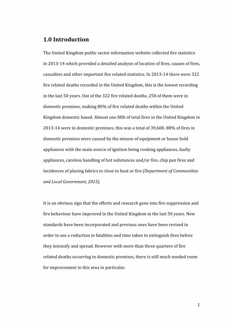
this application. Having fire sprinkler systems installed can extinguish a fire
3
before it spreads, significantly reducing fatalities, and reducing property loss
and insurance costs.
Figure 1 Modern fire sprinkler head, (Dr. Jhun, 2015)
A fire related death in a building protected by a fire sprinkler system is a rare
occurrence anywhere in the world (Davies, 2013). Currently fire sprinkler
systems are not commonly seen installed in domestic premises in the United
Kingdom, as the benefits and potential of domestic sprinklers are still not fully
realized. With such a large number of fire related deaths occurring in domestic
premises, the installation of fire sprinkler systems would be the most effective
fire suppression method, making a significant reduction in deaths.
1.1 Background
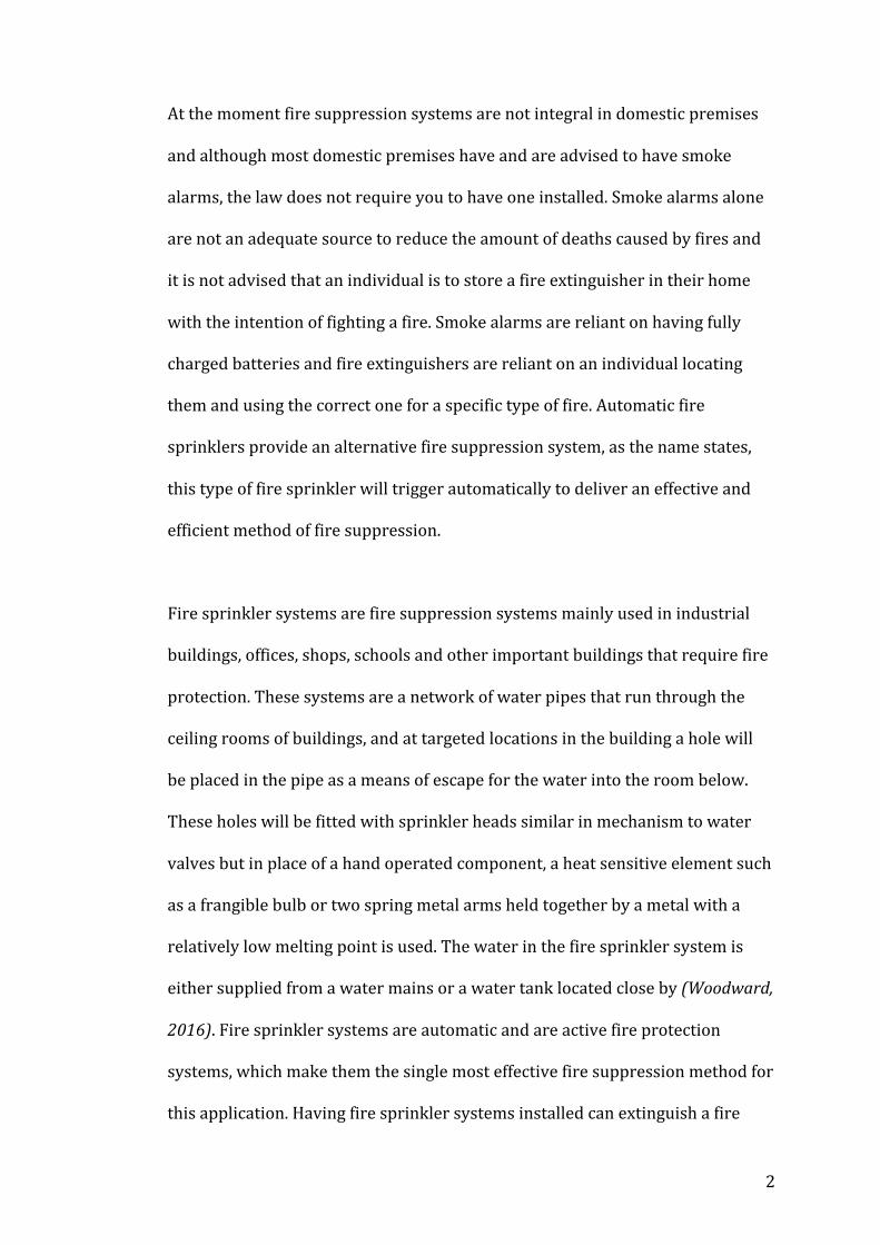
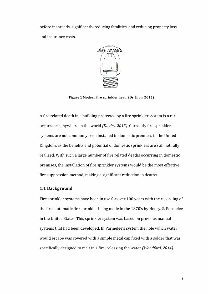
Fire sprinkler systems have been in use for over 100 years with the recording of
the first automatic fire sprinkler being made in the 1870’s by Henry. S. Parmelee
in the United States. This sprinkler system was based on previous manual
systems that had been developed. In Parmelee’s system the hole which water
would escape was covered with a simple metal cap fixed with a solder that was
specifically designed to melt in a fire, releasing the water (Woodford, 2014).
4
Although this simple design was not perfect, it has been the foundation that
current fire sprinklers are based on.
Figure 2 Henry. S. Parmelee, Automatic fire extinguisher, (Woodford, C. 2014)
With current codes and regulations now requiring the use of these systems in
public buildings, it is of the utmost importance that they are optimally designed.
Current fire sprinkler systems are split into various different types dependent
on the application such as pipe system, nozzles/sprinkler head and water
supply. Sprinkler systems also have key characteristics to be considered such as
velocity, droplet size, flow rate and spray angle.
Fire sprinkler systems have developed over time due to the fact that the
knowledge on fires has grown. It is important to recognize that there are
different classes of fires; fires can behave differently under different
circumstances and in different environments and there are key characteristics
required for a fire to be maintained.

5
1.2 Aims of study
The purpose of this study is to select a common house fire scenario and
determine the optimum characteristics required for a fire sprinkler system to
extinguish that fire effectively and efficiently.
In order to do this, research was completed on:
• Fire behaviour
• Fire suppression systems
• House fire statistics
• Fire sprinkler systems
• Fire dynamics simulator (FDS) and Smoke view (SMV)
These will help make an informed decision concerning what the optimum
characteristics should be. Once the key characteristics have been selected, a
simplified real life fire scenario will be simulated in the CFD software FDS; a
detailed analysis of the results will be made.
1.3 Deliverables
By the end this study, the following material will be delivered:
• Description of different types of fires and fire sprinkler systems
• Literature review relating to the optimum characteristics of fire
sprinklers and parameters affecting those characteristics
• Selected fire scenario and fire sprinkler system
• Calculations to select fire sprinkler system characteristics
• FDS & SMV simulation images
• Analysis of results

6
2.0 Fires and Fire sprinklers
2.1 Fires
A fire is the visible result of a chemical reaction between fuel, oxygen and heat.
This chemical reaction is called the process of combustion. The temperature of
the fuel must be high enough for combustion to begin, also known as the
ignition temperature, the fuel will react with oxygen to release heat energy
causing a fire (Science learn, 2009).
Types of fires
Fires are not all the same; they are categorized into different classes, which are
defined by different fuels and different methods of extinguishing:
• Class A –fires that are ordinary combustibles and consist of fuels such as
wood, paper, fabric, plastic and trash. A simple stream of water can be
used for such fires.
• Class B –fires that are flammable liquids such as gasoline, petroleum, oil
and paraffin. Water should not be used for such fires, to extinguish these
fires a Halon extinguishing agent or a foam extinguishing method must
be used.
• Class C – fires that are combustible gasses such as propane, butane,
methane, etc.
• Class D – fires that are combustible metals such as magnesium,
potassium, etc.
• Class E – fires that involve electrical equipment such as motors or
appliances. Water should not be used for such fires as this can causes a
greater hazard.
7
• Class F – fires which involve cooking oils in well-‐insulated cooking
appliances located in commercial kitchens. These fires are characterized
by high flash points. Water mist is the most effective way of
extinguishing such fires.
(Fire equipment manufacturer’s associate, 2015)
A class A fire is a typical type of fire that occurs in domestic premises, therefore
this study focused on this category (Department of Communities and Local
Government, 2015).
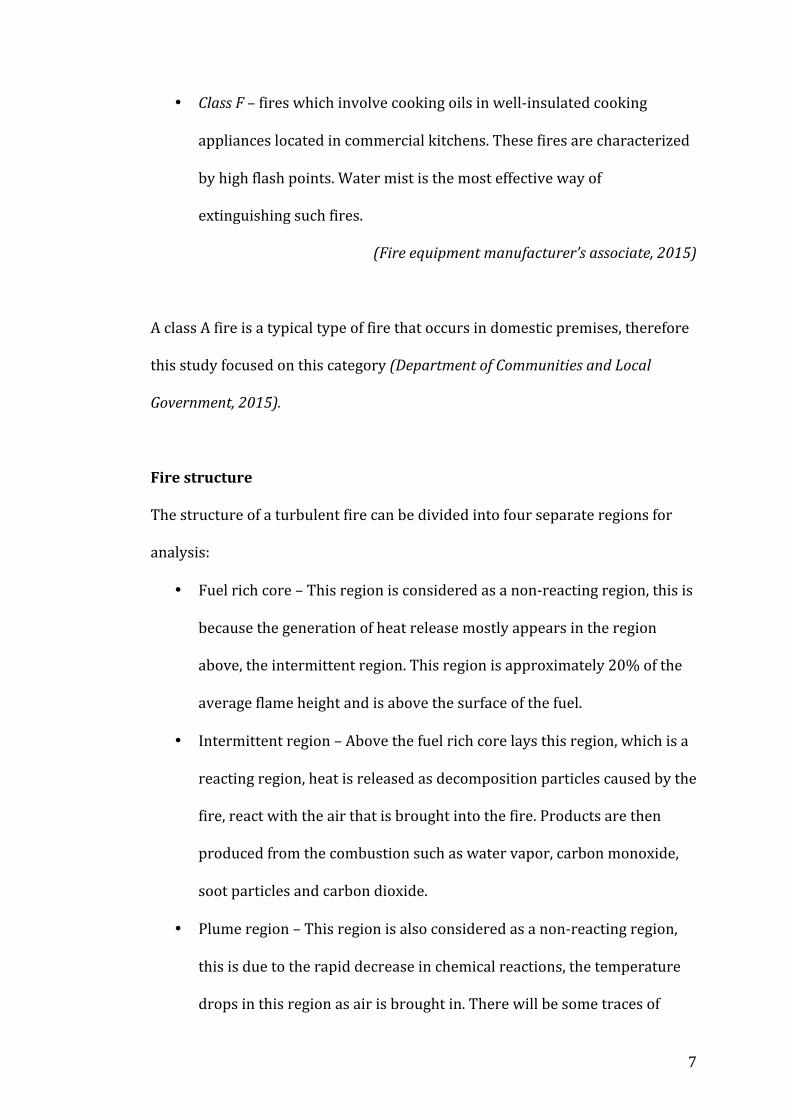
Fire structure
The structure of a turbulent fire can be divided into four separate regions for
analysis:
• Fuel rich core – This region is considered as a non-‐reacting region, this is
because the generation of heat release mostly appears in the region
above, the intermittent region. This region is approximately 20% of the
average flame height and is above the surface of the fuel.
• Intermittent region – Above the fuel rich core lays this region, which is a
reacting region, heat is released as decomposition particles caused by the
fire, react with the air that is brought into the fire. Products are then
produced from the combustion such as water vapor, carbon monoxide,
soot particles and carbon dioxide.
• Plume region – This region is also considered as a non-‐reacting region,
this is due to the rapid decrease in chemical reactions, the temperature
drops in this region as air is brought in. There will be some traces of

8
combustion products such as soot or carbon monoxide but due to the
low temperature reactions do not fully take place.
• Ceiling jet – This region appears inside or in confined areas, this region is
a non-‐reacting region. It consists of gases and products from the fire
rising to the ceiling and spreading outwards.
The structure and shape of fires are very important in understanding fire
behaviour and fire suppression. It is known that the shapes of fires will
change with time and the circumstances surrounding it. Typically the shape
of a turbulent fire can be described as a cylindrical or cone link with the
bottom taken as the pool diameter and the top given by the visible flame
height. Figure 3 shows a typical structure and the different regions of a fire
(Hamins et al., 1995).
Figure 3 Fire structure and regions, (2015)
Fire behaviour
Another important characteristic of fires is their behaviour; fires do not all
behave in the same way with external factors dictating this. Fires can burn
differently, range in different temperatures, have different color flames and
initiate differently. All fires produce gases but some fires produce deadlier
9
gasses than others. The way in which a fire behaves can depend on the fuel and
other factors that affect the fuel, such as initial conditions, surface area, heat
produced, and availability of fuel and oxygen (Science learn, 2009).
The temperature at which fuels begin combustion varies with different fuels.
For every fuel there is a certain amount of heat energy required to change that
fuel into a gas, if it is not already. After that, more heat energy is required to
create the chemical reaction with oxygen, causing the production of a fire
(Science learn, 2009).
The ambient conditions that affect the fuel relate to the humidity of the
atmosphere; if the air is dry it will contribute in drying the fuel, making ignition
quick and easy alternatively if the air is moist ignition will become difficult
(Science learn, 2009).
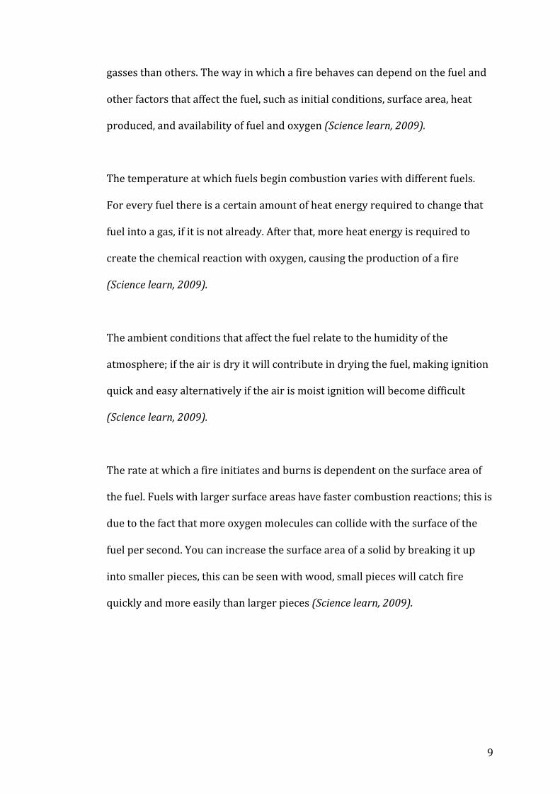
The rate at which a fire initiates and burns is dependent on the surface area of
the fuel. Fuels with larger surface areas have faster combustion reactions; this is
due to the fact that more oxygen molecules can collide with the surface of the
fuel per second. You can increase the surface area of a solid by breaking it up
into smaller pieces, this can be seen with wood, small pieces will catch fire
quickly and more easily than larger pieces (Science learn, 2009).
10
Figure 4 Differences in surface area, (2007-‐2009)
The amount of heat energy release varies in different fuels; some fuels retain a
lot of energy while others do not. The amount of energy release dictates how
quickly the fuel burns; more heat energy will allow the reaction with oxygen to
occur very quickly (Science learn, 2009).
The amount of fuel available will dictate the intensity and duration that the fire
will burn at in terms of heat energy output or heat release rate. The more fuel
available the more intense and longer the fire will burn for. The amount of fuel
available is also known as the ‘fuel load’ (Science learn, 2009).
Similarly to the amount of heat energy available, the amount of oxygen available
will depend on how quickly the reaction will occur and the rate of burning. A
low concentration of oxygen also known as the ‘back draught’ will slow down
burning and cause smoldering, if there is then an increase in oxygen the fire will
immediately grow (Science learn, 2009).
11
Pool fires & Jet fires
When fires begin they can start as one of the following:
• A pool fire -‐ a turbulent diffusion fire resulting from the combustion of a
fuel, where the fuel has zero or low initial momentum.
• A jet fire -‐ a turbulent diffusion fire resulting from the combustion of a
fuel continuously released with some significantly high initial
momentum.
(Health and safety executive, 2016)
2.2 Fire Sprinklers
Fire sprinkler systems are fire suppression systems that are commonly used in
industrial buildings, offices, residential buildings and other buildings that are
deemed important. Due to the frangible bulb component in fire sprinklers, they
are classified as active fire protection measures.
Types of fire sprinklers systems
There are several different types of fire sprinklers with different functionality
between them; this is because they have different applications.
Wet pipe
The wet pipe system is the quickest responding system, as per the name this
system always has water within the pipes of the system; this water is also under
a considerable amount of pressure. The combination of these two factors allow
for a rapid response when the sprinkler head is activated. The wet pipe system
is commonly used in buildings such as offices, it is cost effective, easy to
12
maintain, easy to install and reliable. The risks with this system is that if the
pipes are damaged there is the possibility of leaks and if the system is installed
in an environment with extremely cold weather, the water is at risk of freezing
(Tyco, 2016).
Dry pipe
In contrast to the wet pipe system, this system does not have water readily
available within the pipes of the system, instead of water the pipes are filled
with pressurized air; this pressurized air keeps a valve closed that retains the
water. When the sprinkler head is activated, the air is released, which allows the
water to flow through the pipes and then out through the sprinkler head. The
obvious downside to this is that there is a delay before the water actually exits
the sprinkler head however the advantage of this system is that it releases a
large amount of pressurized water. The dry pipe system is a very expensive and
complicated system to install and maintain. These systems are used in buildings
such as warehouses where there is exposure to extremely cold temperatures
that will cause a risk of the water freezing in the pipes (Tyco, 2016).
Alternate pipe
This system is a combination of the wet pipe system and dry pipe system; this
alternation happens between different times of the year; during the summer
time when there is no risk of the water freezing, the system is filled with
pressurized water, achieving a wet pipe system. During the wintertime when
there is a risk of the water freezing the pipes are instead filled with pressurized
air. Of course this system is extremely costly and difficult to install and maintain
13
but can be used across various types of buildings where there is a risk of the
water freezing only during winter (Tyco, 2016).
Pre-‐action pipe
This system is similar to the dry pipe system in which it initially does not have
the system pipes filled with water but with compressed air. What differentiates
this system from a dry pipe system is that this system requires two triggers. The
first trigger being a device such as a smoke detector, once this trigger is
activated, water is then released into the pipe system. The second trigger will be
the fire sprinkler head, once activated will release the water out of the sprinkler
head (Tyco, 2016).
Deluge pipe
Similar in functionality to the pre-‐action pipe system, the deluge pipe system
requires two trigger activations. The difference between the pre-‐action system
and this system is that there is a manual component for the first trigger, such as
a button, a lever or a device that is similar. These systems are commonly seen in
chemical plants or hazardous areas (Tyco, 2016).
2.3 Fire suppression method using water
Water spray
Water spray is the commonly seen mode of spray; which is defined by the size
of droplets released from the sprinkler head. The range is typically between
100-‐1000µm (Grant et al., 2000). Water spray systems can be categorized in
either medium or high velocity.
14
High velocity water sprays provide coverage in wide areas over a short amount
of time. To create this high velocity the system would have an increased flow
rate and pressure.
Medium velocity sprays provide better coverage on a smaller area than high
velocity sprays but are used in different applications where the size and type of
fire risk is not as great (Tyco, 2016).
Water mist
Water mist is defined by the droplet sizes being in the range of 10-‐100 µm. This
mode of spray is highly efficient and effective way of fire suppression, this is due
to the size of the water droplets; the smaller droplets allow coverage of a larger
surface area, this in turn increases the heat absorption of the droplets,
extinguishing the fire quickly. The heat of the fire converts the water mist into
steam, which then covers the fire and prevents oxygen from reaching it; the
steam also reduces the heat output.
Not all types of fires can be easily extinguished with smaller droplets alone,
other characteristics of the fire sprinkler are key to ensure that the droplets get
to the fire core; even then, an increase in droplet size may be necessary (Tyco,
2016).
15
2.4 Spray Characteristics
When designing or selecting a fire sprinkler system it is very important to
consider the characteristics of the spray, all equally as important as the other
contributing to the extinguishment of a fire. The spray characteristics are
dependent on the type of fire, heat release rate and size of the fire that could
possibly grow and the dimensions of the room.
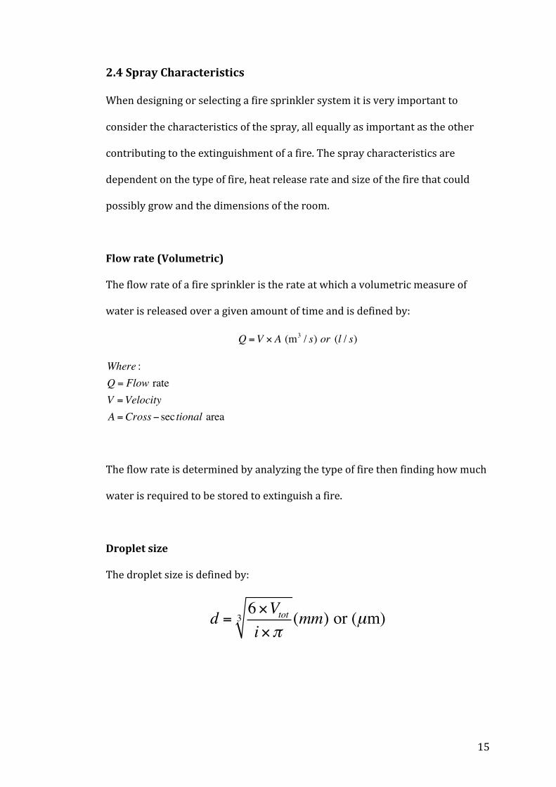
Flow rate (Volumetric)
The flow rate of a fire sprinkler is the rate at which a volumetric measure of
water is released over a given amount of time and is defined by:
Q =V × A (m3 / s) or (l / s)
Where :Q = Flow rateV =VelocityA =Cross− sec tional area
The flow rate is determined by analyzing the type of fire then finding how much
water is required to be stored to extinguish a fire.
Droplet size
The droplet size is defined by:
d = 6×Vtoti×π
3 (mm) or (µm)
16
Where :i = Droplet of equal volumed = Droplet diamaterπ= piVtot = Total volume
(Grant et al., 2000)
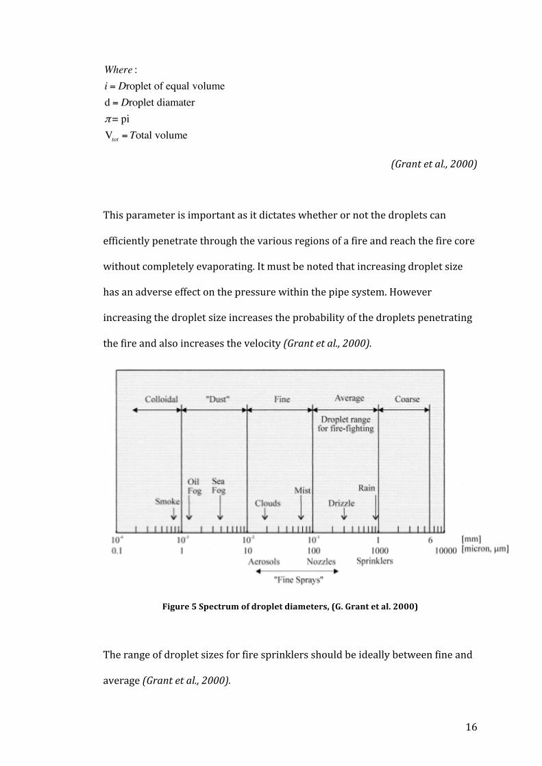
This parameter is important as it dictates whether or not the droplets can
efficiently penetrate through the various regions of a fire and reach the fire core
without completely evaporating. It must be noted that increasing droplet size
has an adverse effect on the pressure within the pipe system. However
increasing the droplet size increases the probability of the droplets penetrating
the fire and also increases the velocity (Grant et al., 2000).
Figure 5 Spectrum of droplet diameters, (G. Grant et al. 2000)
The range of droplet sizes for fire sprinklers should be ideally between fine and
average (Grant et al., 2000).
17
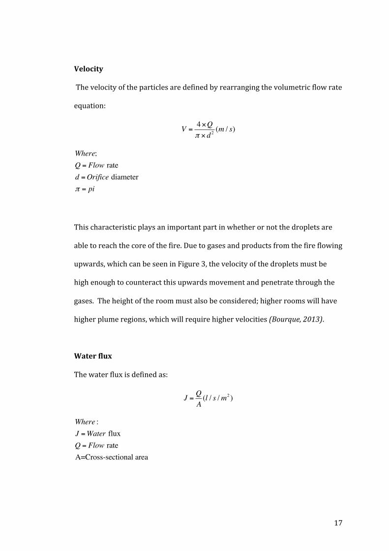
Velocity
The velocity of the particles are defined by rearranging the volumetric flow rate
equation:
V =4×Qπ × d 2
(m / s)
Where;Q = Flow rated =Orifice diameterπ = pi
This characteristic plays an important part in whether or not the droplets are
able to reach the core of the fire. Due to gases and products from the fire flowing
upwards, which can be seen in Figure 3, the velocity of the droplets must be
high enough to counteract this upwards movement and penetrate through the
gases. The height of the room must also be considered; higher rooms will have
higher plume regions, which will require higher velocities (Bourque, 2013).
Water flux
The water flux is defined as:
J = QA(l / s /m2 )
Where :J =Water fluxQ = Flow rateA=Cross-sectional area

18
The water flux is a measure of volumetric flow rate over cross-‐sectional area
and is the amount of water that is released under the sprinkler (Bourque, 2013).
It is dependent on the intensity of the fire, if you have a fire with a high power
output, a large amount of water will be required to cover that area and
extinguish the fire.
Figure 6 Water flux, (2015)
Shape of spray (Spray angle)
The shape of spray dictates the spray coverage on the fire. As per Figure 7 and 8
there are different types of spray patterns. The traditional and modern upright
sprinkler head project the spray upwards and have deflectors that spray the
water below, the traditional upright provides ceiling protection by wetting and
cooling the ceiling, opposed to the modern upright. Commonly seen pendant
sprinkler heads hang down from the ceiling and spray the water in a circular
19
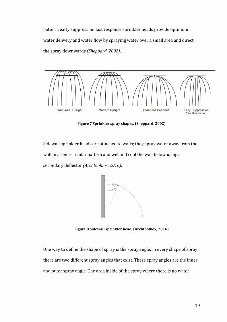
pattern, early suppression fast response sprinkler heads provide optimum
water delivery and water flow by spraying water over a small area and direct
the spray downwards (Sheppard, 2002).
Figure 7 Sprinkler spray shapes, (Sheppard, 2002)
Sidewall sprinkler heads are attached to walls; they spray water away from the
wall in a semi-‐circular pattern and wet and cool the wall below using a
secondary deflector (Archtoolbox, 2016).
Figure 8 Sidewall sprinkler head, (Archtoolbox, 2016)
One way to define the shape of spray is the spray angle; in every shape of spray
there are two different spray angles that exist. These spray angles are the inner
and outer spray angle. The area inside of the spray where there is no water

20
defines the inner spray angle and the outer area of the spray defines the outer
spray angle (Bourque, 2013).
Figure 9 Outer spray angle, (Rein, 2008)
Spray offset
The distance from the sprinkler head in which water droplets are fully formed is
called the spray offset (Bourque, 2013). The process of which the droplets are
produced is called atomization; the stages of atomization are described in figure
10 (Marshall, 2004).
Figure 10 Process of atomization, (Marshall, 2004)
21
3.0 Fire Dynamics Simulator 6 (FDS) & SmokeView
(SMV)
3.1 Introduction to FDS & SMV
Fire Dynamic Simulator (FDS), is a computational fluid dynamics model of fire-‐
driven fluid flow. FDS solves numerically a form of the Navier-‐Stokes equations
(shown in appendix 14.3) appropriate for low speed, thermally driven flow
(Pool fires) with an emphasis on smoke and heat transfer.
FDS was publicly released in February 2000. To date, roughly half of the
applications of the software have been used for the design of smoke handling
systems and sprinkler/detector activation studies. The other half consists of
residential and industrial fire reconstruction. Throughout the years of
development, FDS has been aimed at solving practical fire problems in fire
suppression, while at the same time providing a tool to study fundamental fire
dynamics and combustion
Smokeview is a scientific software that comes packaged with FDS. It is tool
designed for visualizing numerical prediction generated by fire models such as
FDS. FDS and Smokeview are primarily used to model and visualize time-‐
varying fire phenomena. Smokeview performs visualizations by displaying time
dependent tracer particle flow, animated contour slices of computed gas
variables and surface data. Smokeview also presents contours and vector plots
of static data anywhere within a simulation scene at a fixed time (NIST Special
Publication 1019, 2015).
22
FDS & Smokeview must be discussed as the selected simulations are to be
carried out on this software to evaluate the optimum sprinkler spray
characteristics for fire suppression. It is also important to discuss why this
software is being used for this project.
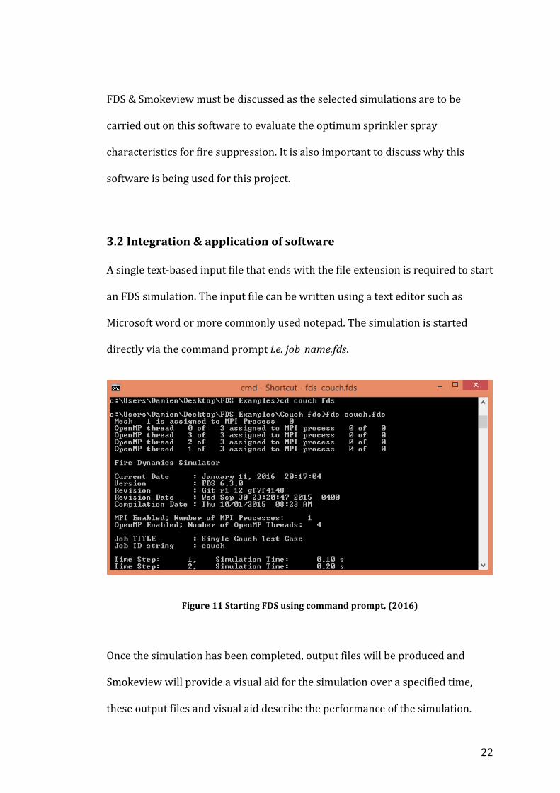
3.2 Integration & application of software
A single text-‐based input file that ends with the file extension is required to start
an FDS simulation. The input file can be written using a text editor such as
Microsoft word or more commonly used notepad. The simulation is started
directly via the command prompt i.e. job_name.fds.
Figure 11 Starting FDS using command prompt, (2016)
Once the simulation has been completed, output files will be produced and
Smokeview will provide a visual aid for the simulation over a specified time,
these output files and visual aid describe the performance of the simulation.
23
In order to create a FDS input file there are certain steps that are required to be
completed, these are described in greater detail in 8.0.
FDS and Smokeview was used in this project as it has ideal applications; these
include fire sprinkler activation study and fire suppression. When using this
software for such applications, it will take the following key characteristics into
consideration that are crucial for this project.
• Sprinkler head
• Droplet diameter
• Activation temperature
• Response time index
• Flow rate
• Spray offset
• Particle velocity
• Spray angle
• Heat release rate
The purpose of the simulation was to create a typical fire scenario in a domestic
premise with real life values and demonstrate how to extinguish that fire with
pre-‐determined characteristics for the fire sprinkler system.
3.3 Case study
To provide a better understanding of FDS and Smokeview and how it relates to
this project, an analysis of two of the existing input files took place.
24
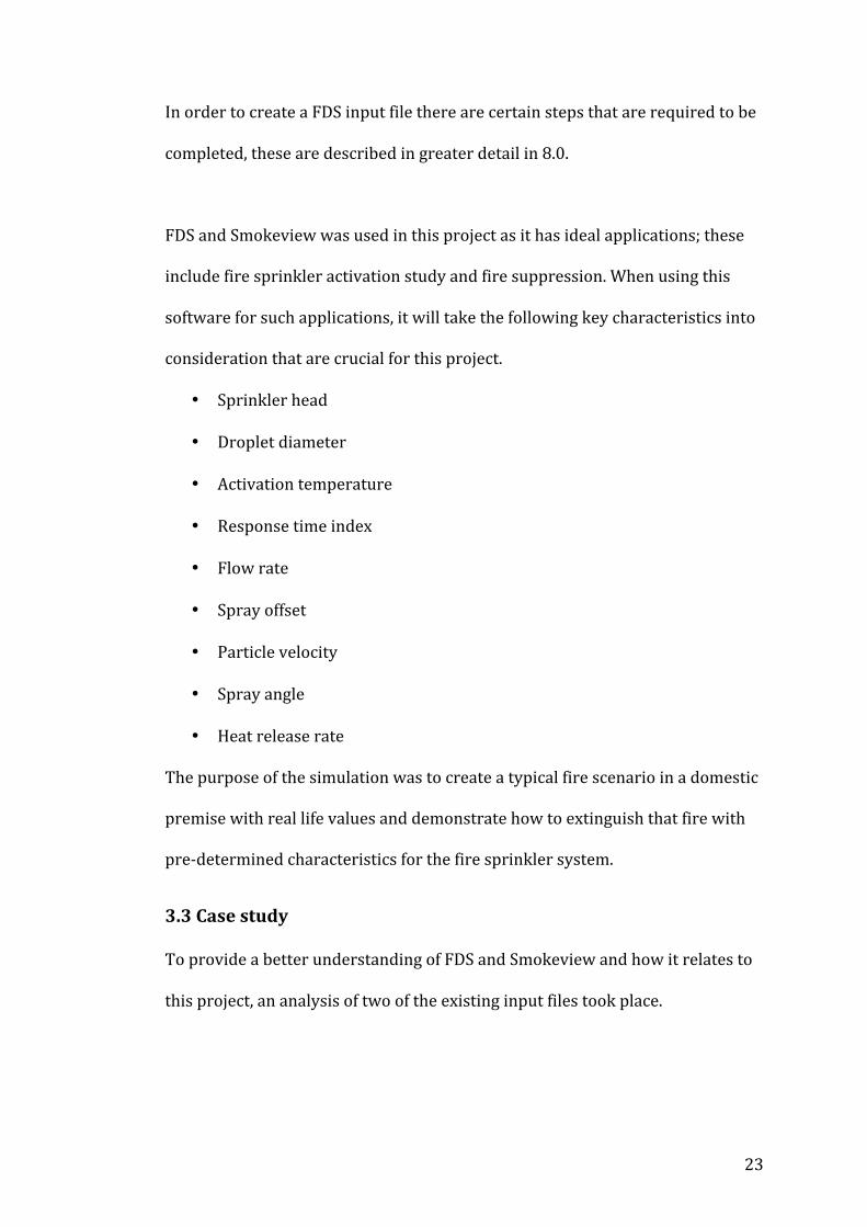
The first example is of a couch situated in a living room that is burning over a
period of 600 seconds. This is a very useful example, which is relative to this
study as it demonstrates a fire scenario that could occur in a domestic premise
and provides output values. The Input file for the burning couch can be seen in
figure 13 where all boundaries and parameters about the scenario are defined.
Figure 12 FDS input file for burning couch, (2016)

25
Once the simulation is completed, the Smokeview visual can be viewed, this is
shown in figure 13; where the couch has been burning for a period of 500
seconds. Everything that can be seen in the Smokeview file has been specified
within the input file.
Figure 13 Smokeview visual of burning couch & temperature slice file, (2016)
Flow patterns can be seen and slices of data can be shown, either in the gas or
solid phase by including the slice file and or boundary file name list group in the
input file. A slice file of the burning couch can be seen in figure 14, which
displays the temperature on a specified plane; this can also be on a line or
volume depending on the boundaries set. Other quantities such as conductivity,
enthalpy and heat release rate can also be specified using the slice file.
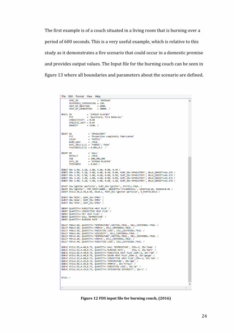
The second example is of a fire, which is then suppressed using a fire sprinkler
after a specified amount of time; if required the fire sprinkler can also be
activated when the sprinkler head reaches a temperature that is specified
26
within the input file. This example is relative to this study as it demonstrates
fire suppression with the use of a fire sprinkler. Similarly to the previous
example, all parameters and boundaries of the fire scenario that are seen in the
Smokeview file must be specified within the input file.
Figure 14 Smokeview visual of fire suppression using a fire sprinkler, (2016)
4.0 Literature review
4.1 Fire suppression by water sprays
One of the first key topics researched include fire suppression. Grant et al.
explored the classification of fire types, fire suppression of class A fires, class A
fire characteristics and water spray qualities. This research paper is applicable
27
to my project as it directly relates to fire suppression using water sprays; water
sprays being an integral part of fire sprinkler systems.
A major point that was discussed in this paper was the extinguishment of class
A fires by water; it is important to note that the following are key components
to extinguishing these fires:
• Cooling the fuel surface – This reduces the burning rate and the rate of
fuel available to the fire; this in turn has a reduction on the heat release
rate. This method allows easier extinguishment of the fire.
• Cooling the flame zone directly – This reduces the rate of chemical
reactions for combustion, some of the heat normally used to support the
reaction is transferred into heating and evaporating the water droplets,
and this will provide an insufficient amount of heat needed to aid the
reaction for combustion.
• Volumetric displacement of oxygen – As the fire sprinkler provides water
vapor within the area that the fire exists, it displaces the oxygen away
from the fire, which reduces the rate of chemical reactions for
combustion. This has a similarly result to cooling the flame zone directly.
• Wetting combustible surface to control fire spread – Once the fire
sprinkler has activated, the water sprays distributed can pre-‐wet
combustible surfaces within the immediate range of the fire; this
provides a heat-‐sink which effectively delays ignition.
(Grant et al., 2000)
28
The information provided on class A fires are applicable to this project because
they are a common type of fire that occurs in domestic premises and is the type
of fire that will be used for the analysis.
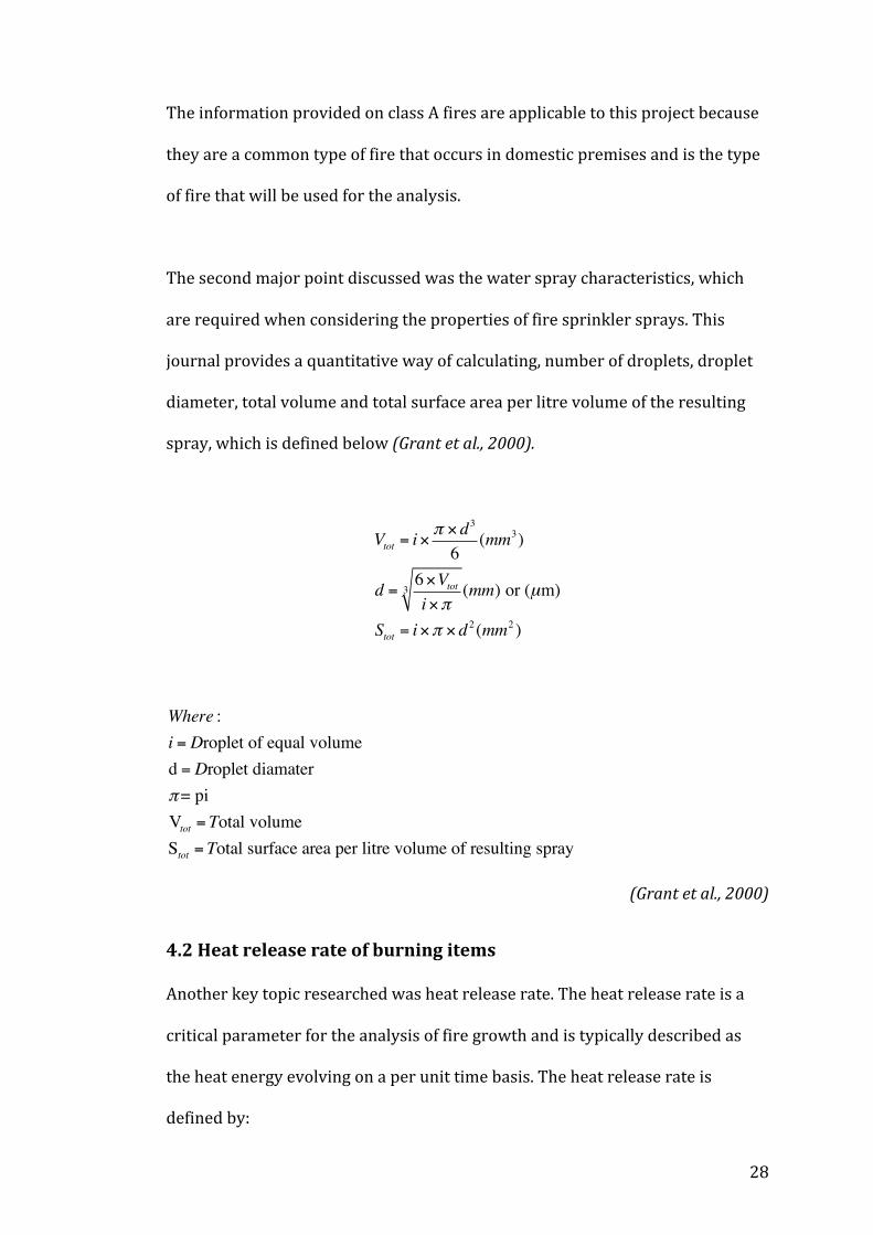
The second major point discussed was the water spray characteristics, which
are required when considering the properties of fire sprinkler sprays. This
journal provides a quantitative way of calculating, number of droplets, droplet
diameter, total volume and total surface area per litre volume of the resulting
spray, which is defined below (Grant et al., 2000).
Vtot = i×π × d3
6(mm3)
d = 6×Vtoti×π
3 (mm) or (µm)
Stot = i×π × d2 (mm2 )
Where :i = Droplet of equal volumed = Droplet diamaterπ= piVtot = Total volumeStot = Total surface area per litre volume of resulting spray
(Grant et al., 2000)
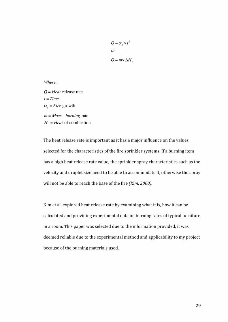
4.2 Heat release rate of burning items
Another key topic researched was heat release rate. The heat release rate is a
critical parameter for the analysis of fire growth and is typically described as
the heat energy evolving on a per unit time basis. The heat release rate is
defined by:
29
Q.=αg × t
2
or
Q.=m
.×ΔHc
Where :
Q.= Heat release rate
t = Timeαg = Fire growth
m.=Mass− burning rate
Hc = Heat of combustion
The heat release rate is important as it has a major influence on the values
selected for the characteristics of the fire sprinkler systems. If a burning item
has a high heat release rate value, the sprinkler spray characteristics such as the
velocity and droplet size need to be able to accommodate it, otherwise the spray
will not be able to reach the base of the fire (Kim, 2000).
Kim et al. explored heat release rate by examining what it is, how it can be
calculated and providing experimental data on burning rates of typical furniture
in a room. This paper was selected due to the information provided, it was
deemed reliable due to the experimental method and applicability to my project
because of the burning materials used.
30
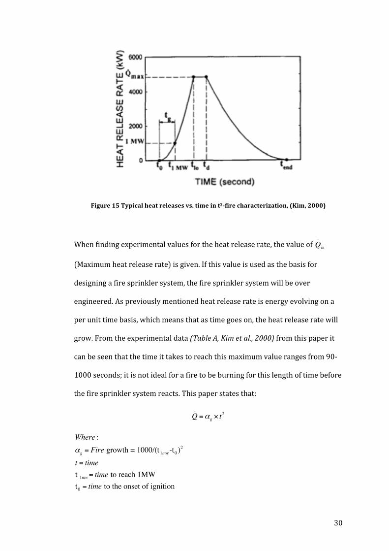
Figure 15 Typical heat releases vs. time in t2-‐fire characterization, (Kim, 2000)
When finding experimental values for the heat release rate, the value of Q.
m
(Maximum heat release rate) is given. If this value is used as the basis for
designing a fire sprinkler system, the fire sprinkler system will be over
engineered. As previously mentioned heat release rate is energy evolving on a
per unit time basis, which means that as time goes on, the heat release rate will
grow. From the experimental data (Table A, Kim et al., 2000) from this paper it
can be seen that the time it takes to reach this maximum value ranges from 90-‐
1000 seconds; it is not ideal for a fire to be burning for this length of time before
the fire sprinkler system reacts. This paper states that:
Q.=αg × t
2
Where :αg = Fire growth = 1000/(t1mw -t0 )2
t = timet 1mw= time to reach 1MWt0 = time to the onset of ignition
31
(Kim, 2000)
If values for t1MW and tO are provided then αg can be calculated. The value for t
will then be the ideal time for a sprinkler to activate after a fire has started; this
is typically between 30-‐50 seconds. Inserting these values into the heat release
rate equation will provide the heat release rate for the specified time, t.
4.3 Residential sprinkler systems
Madrzykowski et al. discussed the importance of automatic sprinkler systems
being incorporated in residential premise. This paper is relevant to this project
as it discusses the research and development for a solution to fires in homes; it
also contains statistics on fires in homes.
A very important topic discussed by Madrzykowski et al. is the measuring of
sprinkler sensitivity. The research and testing for sprinkler sensitivity was done
by several fire research institutes, which include FM Global Research, USFA,
BFRS and NIST.
In 1990 an agreement was reached within the International Standards
organization – sprinkler and water spray equipment group, to create a standard
for sprinkler sensitivity requirements and testing; this produced the standard
“Requirements and methods for sprinklers”. The standard was created by using
tests completed in labs that established ranges of sprinkler sensitivity
characteristics. These ranges of sensitivity are based both on the response time
index (RTI) of the device and on its conductivity (C). RTI is a measure of pure
32
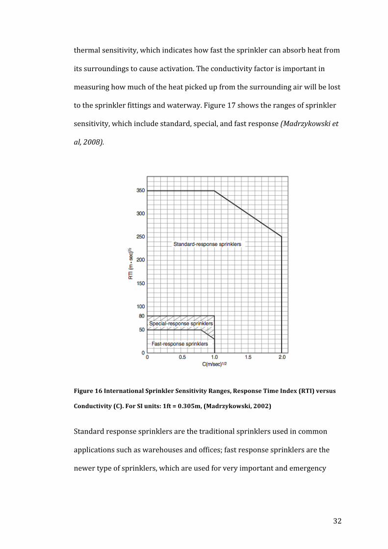
thermal sensitivity, which indicates how fast the sprinkler can absorb heat from
its surroundings to cause activation. The conductivity factor is important in
measuring how much of the heat picked up from the surrounding air will be lost
to the sprinkler fittings and waterway. Figure 17 shows the ranges of sprinkler
sensitivity, which include standard, special, and fast response (Madrzykowski et
al, 2008).
Figure 16 International Sprinkler Sensitivity Ranges, Response Time Index (RTI) versus
Conductivity (C). For SI units: 1ft = 0.305m, (Madrzykowski, 2002)
Standard response sprinklers are the traditional sprinklers used in common
applications such as warehouses and offices; fast response sprinklers are the
newer type of sprinklers, which are used for very important and emergency
33
situations. Special response sprinklers are bespoke sprinklers that conform to
appropriate installation standards.
Sprinkler response time as a function of the temperature rating of the heat
sensitive element is well understood; that is, a 74°C rated sprinkler will operate
when its temperature reaches 74°C, plus or minus a few degrees.
The Response Time Index (RTI) gives a good measure of sprinklers sensitivity.
The smaller the RTI is the faster the sprinkler operation will be. Standard-‐
response sprinklers have an RTI range of 180 to 650 sec1⁄2ft1⁄2 (100 to 350
sec1⁄2m1⁄2), but the RTI range for residential sprinkler systems is around 50
to 90 sec1⁄2ft1⁄2 (28 to 50 sec1⁄2m1⁄2).
The conductivity describes the loss of heat from the sprinkler heat sensitive
element to the sprinkler frame; it’s mounting, and even the water within the
system (Madrzykowski et al, 2008).
It is important to understand the RTI as it is a parameter that can be adjusted in
the FDS input file.
4.4 Overview of sprinkler technology research
Yao examined an overview of continuing sprinkler technology research and
practical applications. The aforementioned research consists of the controlling
of variables of a fire sprinkler and development of tools and deterministic
computer models to predict fire protection performance. Similarly to the
previous paper on residential fire sprinklers, this paper discusses and explains
the response time index (RTI). Most importantly this paper provides a
34
quantifiable method of calculating the Response Time Index This is important to
the project as the response time index is a characteristic for fire sprinklers and
is a considered variable in the FDS software.
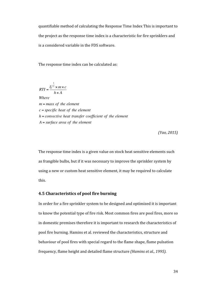
The response time index can be calculated as:
RTI =U12 ×m× ch× A
Wherem =mass of the elementc = specific heat of the elementh = convective heat transfer coefficient of the elementA = surface area of the element
(Yao, 2015)
The response time index is a given value on stock heat sensitive elements such
as frangible bulbs, but if it was necessary to improve the sprinkler system by
using a new or custom heat sensitive element, it may be required to calculate
this.
4.5 Characteristics of pool fire burning
In order for a fire sprinkler system to be designed and optimized it is important
to know the potential type of fire risk. Most common fires are pool fires, more so
in domestic premises therefore it is important to research the characteristics of
pool fire burning. Hamins et al. reviewed the characteristics, structure and
behaviour of pool fires with special regard to the flame shape, flame pulsation
frequency, flame height and detailed flame structure (Hamins et al., 1995).
35
Pool fires are fires resulting from the combustion of a fuel, where the fuel has
zero or low initial momentum and are configured horizontally. The fuel in pool
fires can be a liquid, gas or solid; the base of the fuel may be of non-‐uniform
geometry. Pool fires can be characterized by several parameters, which include
heat release rate and power radiated to the surroundings, pool fires can also be
affected by ambient conditions such as humidity and surrounding temperature.
The conditions affecting the fire influence the structure and potential risk of a
fire (Hamins et al., 1995).
Hamins et al. provided a detailed explanation on the flame shape and height. It
is commonly accepted that the more fuel available to the fire, the larger the heat
release rate will be and the higher the flame will be. Pool fire Froude modeling
suggest that the ratio of inertia to buoyant forces are the key in simulating the
fluid dynamic aspects of pool fires. Four regions can describe the structure of a
buoyant fire; a fuel rich core, the intermittent region, the plume region and the
ceiling jet; these regions are further explained in section 4.2. The shape and
height of a fire have important implications in terms of fire hazard. If a fire is in
an enclosed area, direct heat transfer to a ceiling may have dramatic
consequences in terms of time to flashover (NIST, 1995).
Knowledge of these factors is essential to understanding the structure and
behaviour of fires, this knowledge will aid in understanding how the fire
sprinkler characteristics has an affect on extinguishing a fire.
36
4.6 Computational modeling of fire sprinkler spray characteristics
using the fire dynamics simulator
Bourque et al. focused on the necessity for a fire sprinkler’s performance to be
tested and assessed before it can become a listed and approved fire sprinkler. In
reality when a fire sprinkler is produced, it will under go an actual density
delivered (ADD) test. An ADD test requires the use of large labs, many staff and
expensive equipment; to perform these tests can be time consuming and costly.
In order to reduce costs and time spent, computational fluid dynamics software,
namely fire dynamic simulator is used to simulate the fire sprinklers
performance. Bourque and Svirsky’s aim was to determine the accuracy of the
fire dynamic simulators prediction of water distribution of a fire sprinkler, and
compare these results to a test conducted in real life (Bourque et al. 2013).
Bourque et al. discussed the characteristics of a fire sprinkler and their
importance which directly relate to the project, it describes and acknowledges
that the major characteristics for characterizing a spray were shape of spray
(spray angle), velocity, droplet size, water flux and spray offset; these
characteristics are further described in section 5.2. It is also important to know
how accurate the fire dynamic software is, as this will support the use of the
software and the final results of the project.
Bourque et al. concluded that after the simulations and tests were conducted to
receive an accurate result from FDS for comparison, better approximations
must then be selected to have a better replication of the real scenario (Bourque
37
et al. 2013). Therefore to receive accurate results, the simulation must be as
close to the real life scenario as possible.
4.7 Spray characteristics of fire sprinklers
Sheppard discussed the lack of progression towards developing analytical
methods of calculating fire sprinkler effectiveness; this paper acknowledged
that this is mainly due to the lack of available information about initial spray
characteristics of fire sprinklers. Sheppard chose a wide selection of sprinklers
and conducts experiments on these, analyzing the results. Sheppard
acknowledged and discussed the key initial spray characteristics as the spray
velocity, droplet size and water flux (Sheppard, 2002).
Sheppard found that the average radial droplet velocity at a distance 0.2m from
the sprinkler orifice is 53% of the water velocity; the maximum spray velocities
ranged from 62% to 120% of the orifice water velocity with a statistically
significant trend for higher maximum velocities from pendant sprinklers .The
median droplet diameter increases with elevation angle and decreases with
increasing pressure. The water flux distribution varies with pressure and
sprinkler type that it is impossible to determine a universal flux distribution
(Sheppard, 2002).
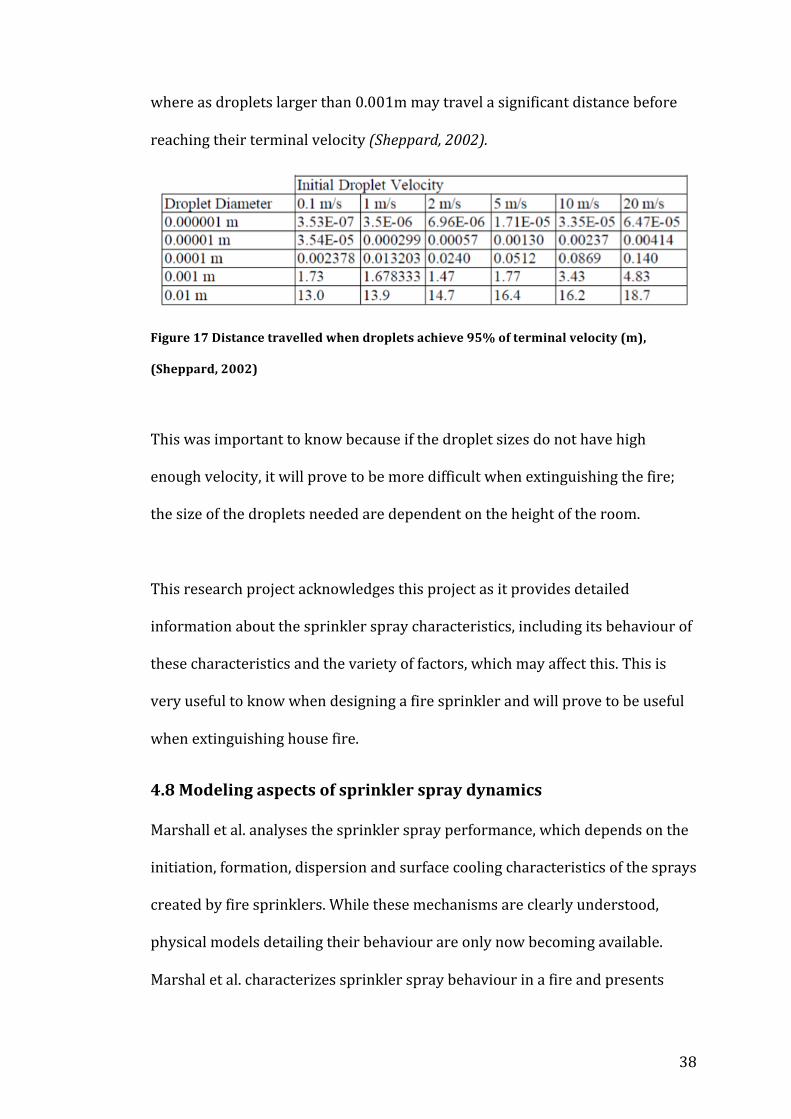
Another useful topic discussed included the distance the droplets travelled
before it reached its highest attainable velocity. Figure shows that droplets
smaller than 0.001m reach their terminal velocity very close to the sprinkler,
38
where as droplets larger than 0.001m may travel a significant distance before
reaching their terminal velocity (Sheppard, 2002).
Figure 17 Distance travelled when droplets achieve 95% of terminal velocity (m),
(Sheppard, 2002)
This was important to know because if the droplet sizes do not have high
enough velocity, it will prove to be more difficult when extinguishing the fire;
the size of the droplets needed are dependent on the height of the room.
This research project acknowledges this project as it provides detailed
information about the sprinkler spray characteristics, including its behaviour of
these characteristics and the variety of factors, which may affect this. This is
very useful to know when designing a fire sprinkler and will prove to be useful
when extinguishing house fire.
4.8 Modeling aspects of sprinkler spray dynamics
Marshall et al. analyses the sprinkler spray performance, which depends on the
initiation, formation, dispersion and surface cooling characteristics of the sprays
created by fire sprinklers. While these mechanisms are clearly understood,
physical models detailing their behaviour are only now becoming available.
Marshal et al. characterizes sprinkler spray behaviour in a fire and presents
39
mathematical models describing the important physical processes for sprinkler
fire suppression (Marshall et al., 2014)
One of the key topics that are discussed within by Marshall et al. was how
sprinkler spray is formed. In order to have a good understanding of the key
characteristics of a fire sprinkler, the formation of the sprinkler sprays must be
understood (Marshall et al., 2014).
Atomization is the process that produces the formation of sprinkler sprays, this
is done by breaking up a stream of liquid into droplets (Marshall et al., 2014).
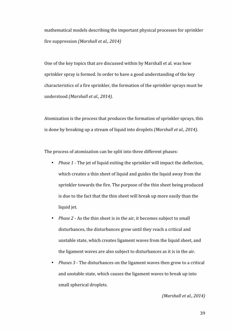
The process of atomization can be split into three different phases:
• Phase 1 -‐ The jet of liquid exiting the sprinkler will impact the deflection,
which creates a thin sheet of liquid and guides the liquid away from the
sprinkler towards the fire. The purpose of the thin sheet being produced
is due to the fact that the thin sheet will break up more easily than the
liquid jet.
• Phase 2 -‐ As the thin sheet is in the air, it becomes subject to small
disturbances, the disturbances grow until they reach a critical and
unstable state, which creates ligament waves from the liquid sheet, and
the ligament waves are also subject to disturbances as it is in the air.
• Phases 3 -‐ The disturbances on the ligament waves then grow to a critical
and unstable state, which causes the ligament waves to break up into
small spherical droplets.
(Marshall et al., 2014)
40
5.0 Selected fire scenario
In order to provide an effective study of fire sprinkler spray characteristics in
domestic premises, it was necessary to analyze the performance of the fire
sprinkler within a fire scenario situated in a domestic premise. For this study a
living room was used as the setting for the fire scenario; typically within this
space there would be several combustible items such as sofas, televisions,
carpet, curtains, etc. To simplify this study, it focused on a single sofa burning in
the center of a room to remove the possibilities of fire spread, the dimensions of
the room are 4.0 x 4.0 x 2.5 m to replicate a typical room size and the room will
not have any doors or windows to remove any external heat transfer.
The selected fire type will be a class A fire for this fire scenario as these types of
fires are the commonly seen in domestic premises and correspond to a typical
living room fire with ordinary combustibles.
The specifications of the sofa selected aimed to replicate a wood frame,
polyurethane foam with olefin fabric; which was experimentally tested by Kim,
H & Lilley, D (heat release rate of burning items, 2000). However the dimensions
of the sofa have been fabricated for this study and are 1.2 x 1.0 x 0.8 m to
replicate a real life sofa size.

41
6.0 Selected Fire Sprinkler System
6.1 Sprinkler system / piping
For the purpose of this study and to replicate an ideal scenario, a dry pipe
sprinkler system was used, this is because there will be no risk of leaking and
there will be a large amount of pressurized water released when the sprinkler is
activated. However, there will be a slight delay before the water is released, as
the water has to travel from its supply, through the system and out of the
sprinkler head, the delay is usually 30 seconds.
6.2 Sprinkler spray / nozzle
The sprinkler head used in this study will be a K-‐11 pendant sprinkler head; this
sprinkler head is commonly seen and is the default sprinkler head in the FDS
and Smokeview software.
6.3 Trigger system
The trigger system was a frangible bulb with an activate temperature of 79oC
and a RTI of 50 (m.s) 1/2. This replicates readily available frangible bulbs to help
the study replicate a real life scenario.
6.4 Fluid
The suppression fluid was water. Water is commonly used for fire suppression
but in extremely hazardous areas such as chemical plants where water cannot
be used foam is often seen as a replacement but in the case of a domestic
premise fire, water is appropriate.

42
7.0 Calculations and specifications
7.1 Flow rate
The British Standard BS9251: 2005 5.2.5.1 System flow rates dictates that a
sprinkler system should be capable of providing flow rates at the sprinkler head
of no less than:
a) For domestic premises
1. 60 litres/min through any single sprinkler; or
2. 43 litres/min through each of two sprinklers operating
simultaneously in a single room
Therefore for this study the range of flow rates that was simulated are;
Q = 60 L /minQ = 80 L /minQ =100 L /minQ =120 L /minQ =140 L /minQ =160 L /minQ =180 L /min
7.2 Orifice diameter
Specifications from Victaulic K11 fire sprinkler standard spray pendant
specifies that the nominal orifice diameter is 16mm, this remained constant
throughout all simulations as FDS only has this model of fire sprinkler head.
do =16mm
(Victaulic, 2014)
43
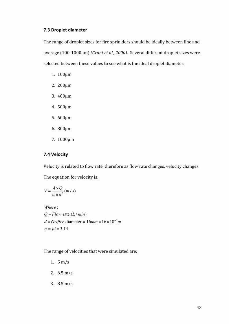
7.3 Droplet diameter
The range of droplet sizes for fire sprinklers should be ideally between fine and
average (100-‐1000μm) (Grant et al., 2000). Several different droplet sizes were
selected between these values to see what is the ideal droplet diameter.
1. 100μm
2. 200μm
3. 400μm
4. 500μm
5. 600μm
6. 800μm
7. 1000μm
7.4 Velocity
Velocity is related to flow rate, therefore as flow rate changes, velocity changes.
The equation for velocity is:
V =4×Qπ × d 2 (m / s)
Where :Q = Flow rate (L /min)d =Orifice diameter = 16mm =16×10−3mπ = pi = 3.14
The range of velocities that were simulated are:
1. 5 m/s
2. 6.5 m/s
3. 8.5 m/s

44
4. 10 m/s
5. 11.4 m/s
6. 13.4 m/s
7. 15 m/s
7.5 Heat release rate
The heat release value can be calculated with the following equation:
Q.=αg × t
2
Where :αg = Fire growth = 1000/(t1mw -t0 )2
(Kim, 2000)
To replicate a real life scenario data was used from Hyeong-‐Jin Kim’s (2000)
paper on heat release rates of burning items. The sofa used was the F32 sofa,
wood frame with polyurethane foam, which had a time to the onset of ignition,
t0 of 75 and a time to reach 1 MW, t1 MW of 150.
Therefore :
αg = Fire growth = 1000/(150-75)2 = 0.17•
or 845
(Kim, 2000)
The ideal time for a sprinkler to activate after a fire has started is between 40-‐
50 seconds. The lower value was selected; therefore the heat release rate after
40 seconds would be calculated.
Q.=
845× 402 = 284.4 kW or j
s

45
(Kim, 2000)
FDS requires the heat release rate per unit area, this can be found by dividing
the heat release rate by the area the fire is covering.
Area, a = 0.5×1m2 = 0.5m2
HRRPUA = 284.4÷ 0.5= 568.8kW /m2
(Kim, 2000)
8.0 Writing FDS Input File
8.1 Specifications
To help reproduce a real life fire scenario, it is important to ensure that all
aspects were as close to a real life as possible.
Scenario – A fire on a sofa in the center of a living room
Room dimensions – 4.0 x 4.0 x 2.5 m
Resolution –10 cm grid cells
Simulation time – 60 seconds
Boundary conditions – Open boundary on one side and ambient temperature of
20oc
Quantities – Wall temperature, net heat flux, radiative heat flux and slice
temperatures.
8.2 Starting input file
The FDS input file must be named, this is defined by ‘&HEAD CHID’ and was
called ‘living_room’. It is also convenient to have a description of the input file so
46
other users to know what the input file consists off; this is defined by ‘TITLE’
and was described as ‘Domain Creation’.
&HEAD CHID='living_room', TITLE='Domain Creation'/
It is important to set a run time, ‘TIME T_END’, for the simulation, for this
simulation the run time was 60 seconds. Setting the simulation time to zero will
only perform initial set up; this will allow the checking of the geometry of the
domain in Smokeview.
&TIME T_END=60.0 /
8.3 Computational mesh
All FDS calculations are completed within the created domain that is
constructed from rectilinear volumes called meshes. Each individual mesh is
divided into rectangular cells; the quality of the results is dependent on the size
of the mesh. The mesh can be coarse, medium or fine.
A measure of the quality of results is given by the non-‐dimensional expression
D*/δx, where D* is the characteristic fire diameter and δx is the nominal size of
the mesh cell in meters. The cell size is dependent on the value of the
characteristic fire diameter, if this value is small then the cell size should also be
small in order to sufficiently resolve the fluid flow and fire dynamics. A
reference within the FDS user guide suggest a D*/δx ratio between 4 and 16 to
accurately resolve fires in several different situations.
47
For this study the mesh cell size was 10cm or 0.1m. This value was taken from
one of the inbuilt examples with similar geometry to what I require. Therefore
δx = 0.1m.
D* is calculated by the following equation:
D*= Qp∞ × cp ×T∞ × g
#
$%%
&
'((
Where :Q = Heat release rate = 284.4kWp∞ = density of air =1.225kg /m3
cp = Specific heat of air =1.005kJ / kg− kT∞ = Ambient temperature = 293Kg = acceleration due to gravity = 9.81D*= 0.58
(NIST, 2015)
Therefore, D*∂x
=0.580.1
= 5.8
This value is between 4 and 16 and means my selected cell size is adequate.
The code written to define this mesh is:
&MESH IJK=40,40,25 XB=0.0,4.0,0.0,4.0,0.0,2.5 /
The number of cells within the domain can be calculated:
40 x 40 x 25 = 40,000

48
8.4 Miscellaneous parameters
There are miscellaneous parameters that can be included in the input file these
parameters include ambient temperature. For this simulation the ambient
temperature was 20oC / 293oK, the code for this was:
&MISC TMPA=20.0/
8.5 Creating obstruction
The sofa has been situated in the centre of the room. The sofa must be of the
dimensions 1.2 x 1.0 x 0.8 m; these dimensions have been taken from a real life
sofa to help replicate a real life scenario. To have this inserted the following
code has been built into the input file.
&OBST XB=1.5,2.5,2.0,2.5,0.0,0.8, SURF_ID='SOFA'/
&OBST XB=1.5,2.5,1.5,2.0,0.0,0.4, SURF_ID='SOFA'/
&OBST XB=2.5,2.6,1.5,2.5,0.0,0.6, SURF_ID='SOFA'/
&OBST XB=1.5,1.4,1.5,2.5,0.0,0.6, SURF_ID='SOFA'/
It is also necessary to assign properties of the sofa, these properties are
necessary for FDS to calculate the combustion and determine how the sofa
burns; the properties selected were taken from an FDS example with a sofa.
&MATL ID='FABRIC', CONDUCTIVITY=0.1, SPECIFIC_HEAT=1.0, DENSITY=100.0
/

49
&SURF ID='SOFA', MATL_ID='FABRIC', COLOR='BROWN', THICKNESS=1.0,
BURN_AWAY=.TRUE. /
8.6 Pyrolysis model and Fuel
To create a fire a heat release rate must be inserted into the input file, to have
this heat release rate it is necessary to specify material properties, (which was
previously mentioned in section 8.5). A specified fire is modeled as the injection
of a gaseous fuel from a solid surface. This is essentially a burner, with a
specified heat release rate per unit area. For this study the heat release rate per
unit area has been calculated to be 568.8 kW/m2.
To input the fire, the location of the fire, heat release rate and e coefficient must
be inserted; the location of the fire is on top of the sofa.
&SURF ID='FIRE', HRRPUA=570, E_COEFFICIENT=4.0 /
&VENT XB=1.5,2.5,1.5,2.0,0.4,0.4 SURF_ID='FIRE'/
Specifying fuel is required; this will cause FDS to use the built-‐in thermo
physical properties for that species when computing quantities. The fuel that
was used is butane; because this is a fuel that can cause fires in a domestic
premise.
50
It is also necessary to insert ‘SOOT_YIELD’, this is the fraction of fuel mass
converted into smoke particles, and this helps to provide a good visual analysis
of the fire. The code for this was below:
&REAC SOOT_YIELD=0.01, FUEL='BUTANE' /
8.7 Particles, droplets and size distribution
To define an evaporating liquid droplet, the gaseous species must be explicitly
specified via the ‘SPEC’ name list group and then the appropriate ‘SPEC_ID’
designated on the part line. The ‘SPEC_ID’ specifies a water vapor, which is a
predetermined species in FDS; the particle will be assigned the thermal
properties of water, the radiation absorption of water and will be colored blue
in SmokeView.
The ideal droplet size for fire suppression is between 100-‐1000μm. Testing will
determine the optimum droplet size but this study began with an initial value of
100μm; the ‘DIAMETER’ name list specifies the droplet size.
&SPEC ID='WATER VAPOR' /
&PART ID='water drops', SPEC_ID='WATER VAPOR',DIAMETER=100 /
8.8 Introduction of sprinkler & Fire suppression by water
To insert a sprinkler into the simulation, it must be inserted into the input file.
The default sprinkler type is a ‘K 11’ sprinkler; the location and properties of the
sprinkler must be specified.
51
&PROP ID='K-‐11', QUANTITY='SPRINKLER LINK TEMPERATURE', RTI=100,
ACTIVATION_TEMPERATURE=79, OFFSET=0.10, PART_ID='water drops',
PARTICLE_VELOCITY=10., SPRAY_ANGLE=30.,80., FLOW_RATE=180 /
&DEVC XYZ=2.0,2.0,2.5, PROP_ID='K-‐11', ID='Spr_1' /
The complete input file can be seen in appendix 14.1.
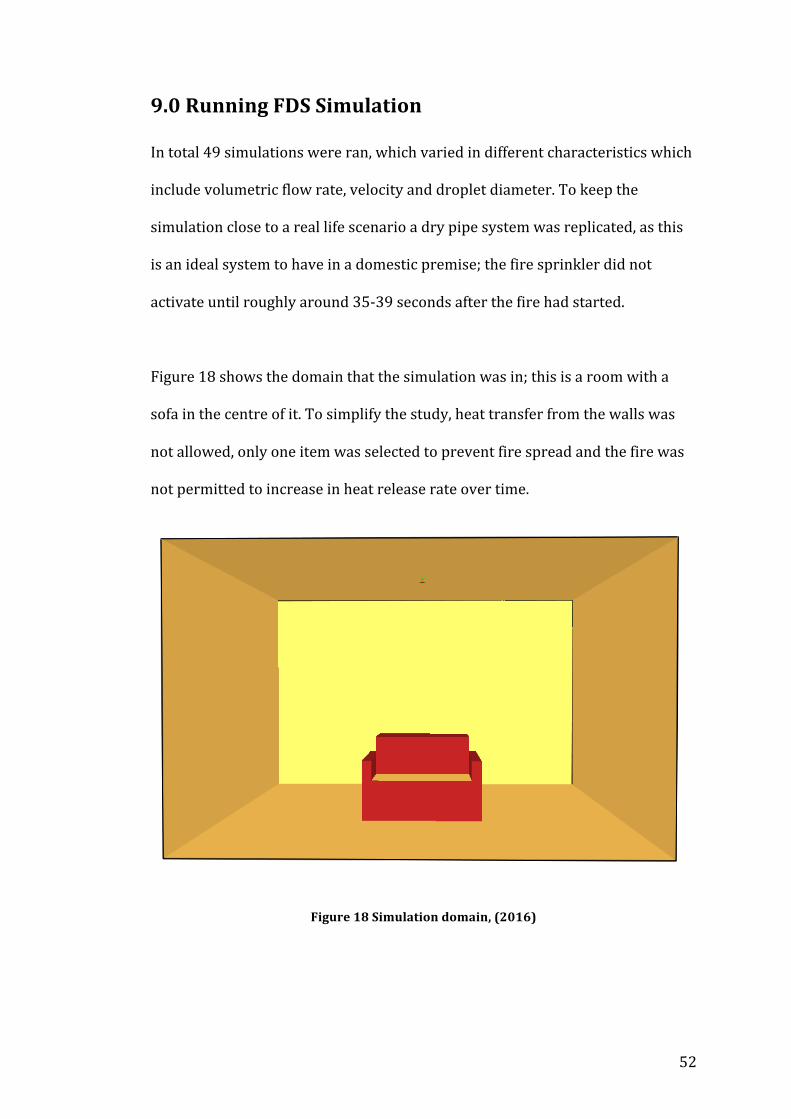
52
9.0 Running FDS Simulation
In total 49 simulations were ran, which varied in different characteristics which
include volumetric flow rate, velocity and droplet diameter. To keep the
simulation close to a real life scenario a dry pipe system was replicated, as this
is an ideal system to have in a domestic premise; the fire sprinkler did not
activate until roughly around 35-‐39 seconds after the fire had started.
Figure 18 shows the domain that the simulation was in; this is a room with a
sofa in the centre of it. To simplify the study, heat transfer from the walls was
not allowed, only one item was selected to prevent fire spread and the fire was
not permitted to increase in heat release rate over time.
Figure 18 Simulation domain, (2016)
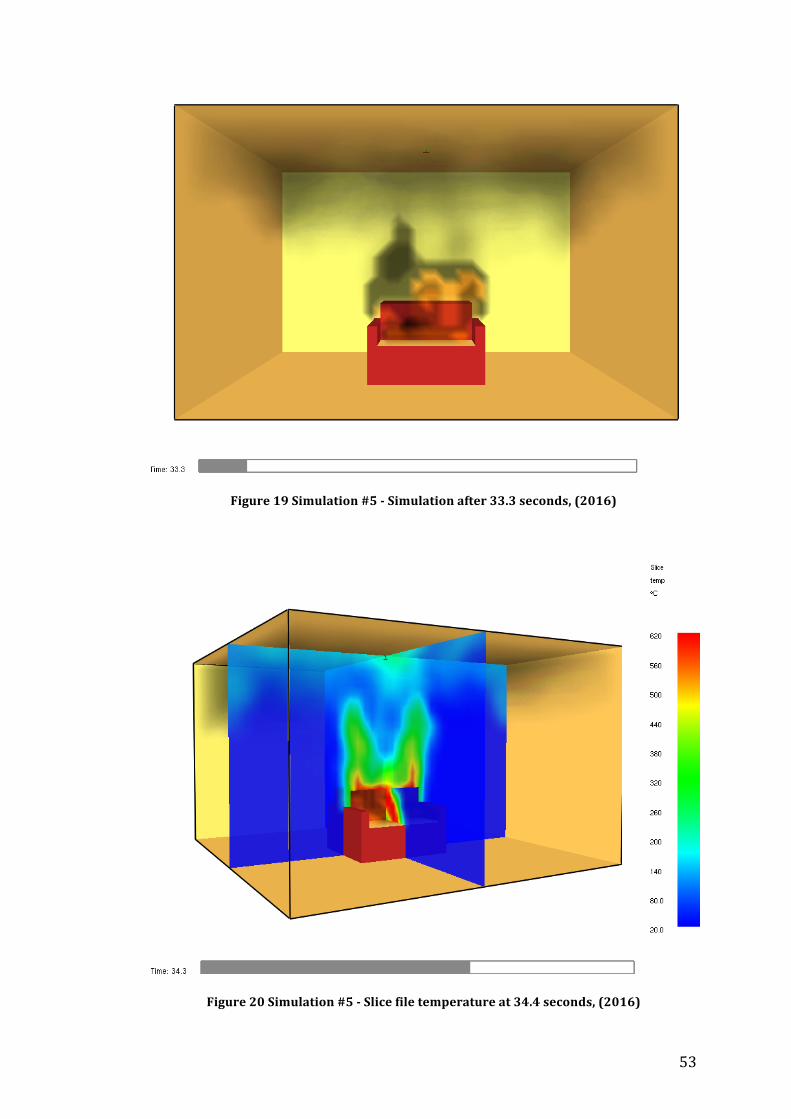
53
Figure 19 Simulation #5 -‐ Simulation after 33.3 seconds, (2016)
Figure 20 Simulation #5 -‐ Slice file temperature at 34.4 seconds, (2016)
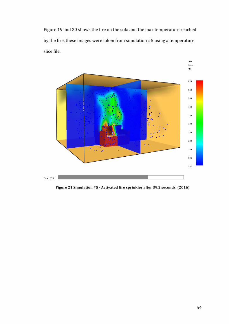
54
Figure 19 and 20 shows the fire on the sofa and the max temperature reached
by the fire, these images were taken from simulation #5 using a temperature
slice file.
Figure 21 Simulation #5 -‐ Activated fire sprinkler after 39.2 seconds, (2016)
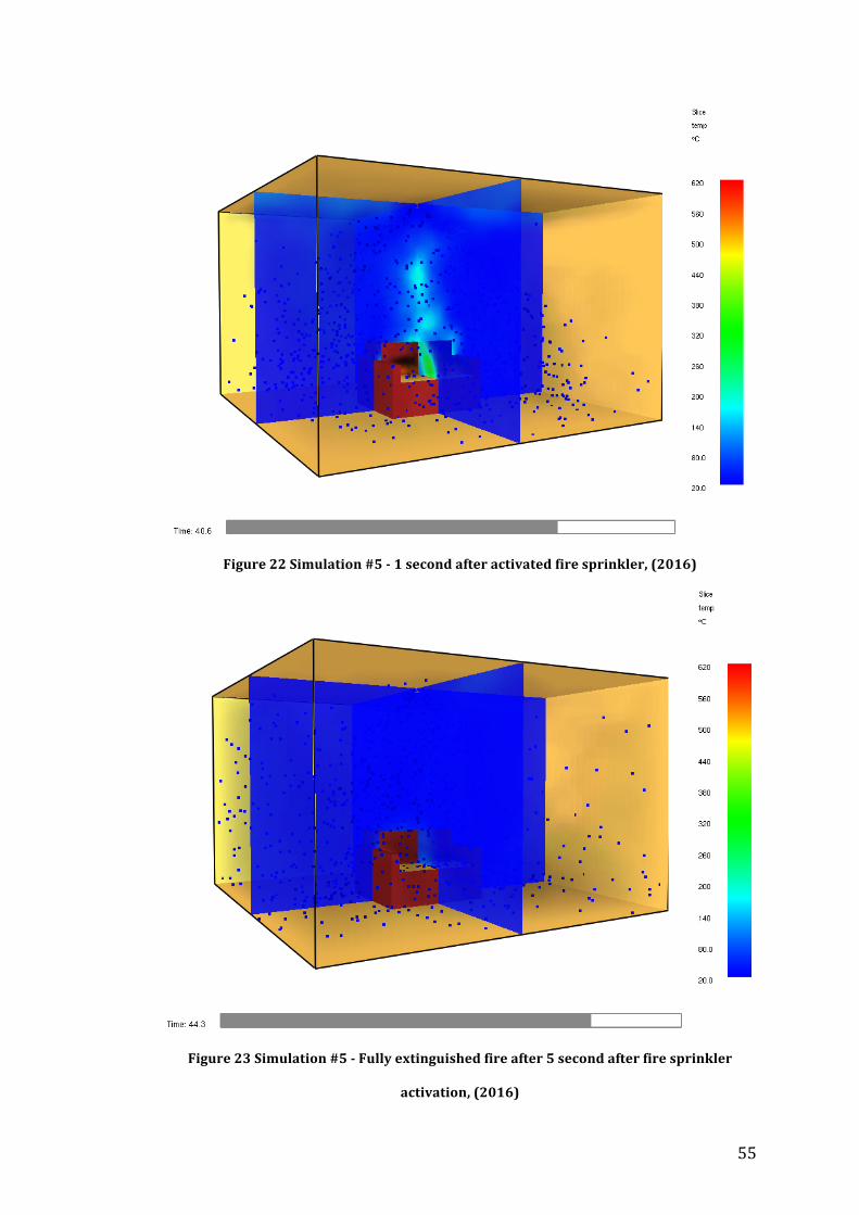
55
Figure 22 Simulation #5 -‐ 1 second after activated fire sprinkler, (2016)
Figure 23 Simulation #5 -‐ Fully extinguished fire after 5 second after fire sprinkler
activation, (2016)
56
Figure 21, 22 and 23 shows the point at which the fire sprinkler was activated
and how the water droplets are suppressing the fire over time until the fire has
been completely extinguished.
10.0 Analysis of FDS results
10.1 Results
The simulations carried out went positively, this is because various different
simulations were carried out with different characteristics, which provided a
range of results to give an adequate analysis. It can be seen from the tabulated
results (shown below) and the graphical results (shown in appendix 14.2) that
during the simulations as the droplet size increases, the time to extinguish the
fire becomes longer; which replicates real life. This is because a reduced droplet
size provides an improved cooling effect on the fire; this is due to the small
droplets covering a larger surface area. This in turn gave an increased rate of
evaporation.
The study indicated that an increase in velocity and flow rate led to prolonged
fire extinguishment. Increasing the flow rate and the velocity will directly
increase the amount of water being used to extinguish the fire and in normal
cases it would be expected that the fire would extinguish quicker. During the
simulations it can be seen that due to the spray angle a large amount of water is
not being sprayed on the fire directly and this water is being distributed on the
surrounding area (shown in figure 24). Although a certain amount of the water
spread to the surrounding area is considered positive, as it prevents fire spread,
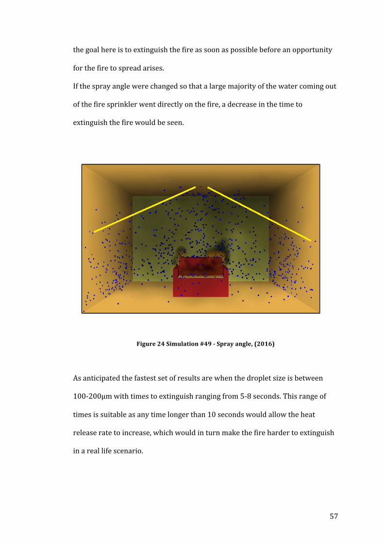
57
the goal here is to extinguish the fire as soon as possible before an opportunity
for the fire to spread arises.
If the spray angle were changed so that a large majority of the water coming out
of the fire sprinkler went directly on the fire, a decrease in the time to
extinguish the fire would be seen.
Figure 24 Simulation #49 -‐ Spray angle, (2016)
As anticipated the fastest set of results are when the droplet size is between
100-‐200μm with times to extinguish ranging from 5-‐8 seconds. This range of
times is suitable as any time longer than 10 seconds would allow the heat
release rate to increase, which would in turn make the fire harder to extinguish
in a real life scenario.
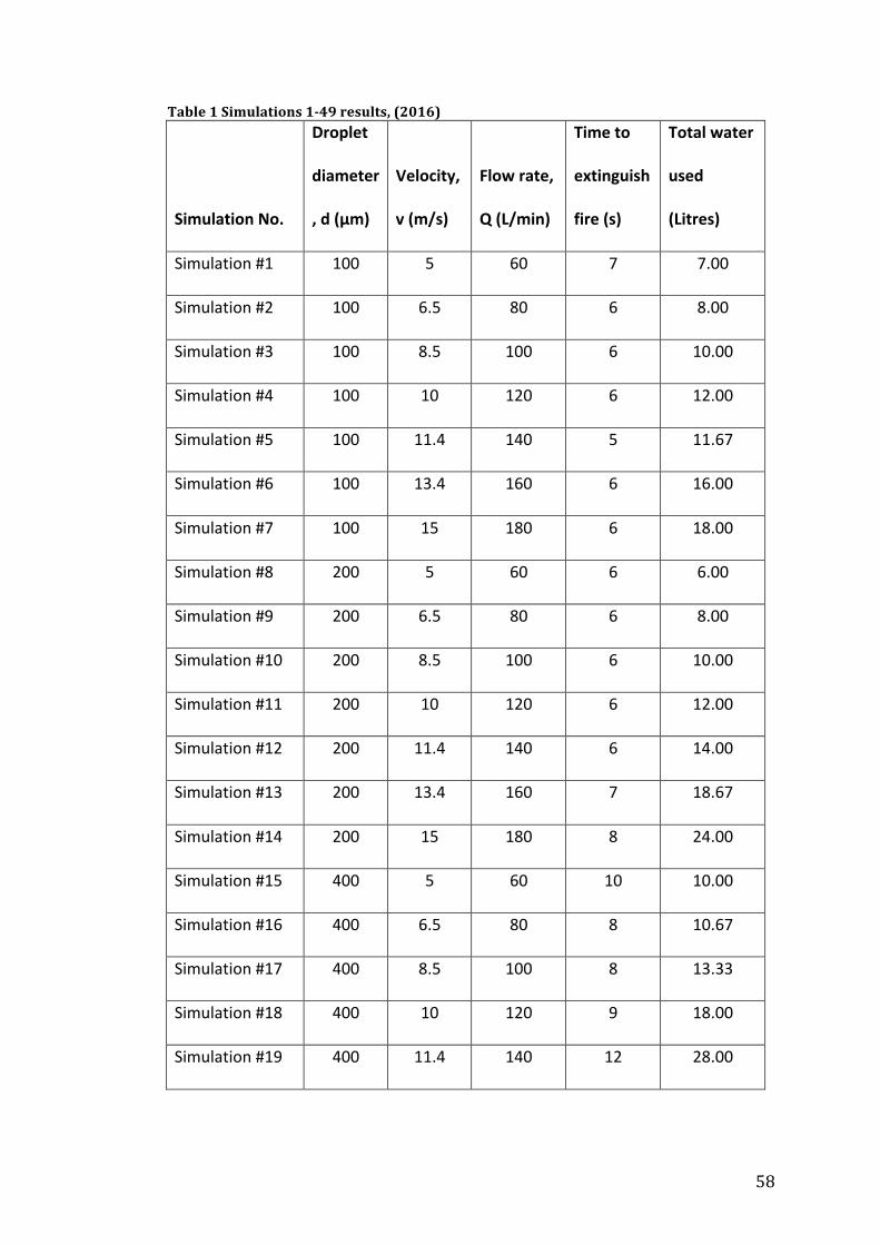
58
Table 1 Simulations 1-‐49 results, (2016)
Simulation No.
Droplet
diameter
, d (μm)
Velocity,
v (m/s)
Flow rate,
Q (L/min)
Time to
extinguish
fire (s)
Total water
used
(Litres)
Simulation #1 100 5 60 7 7.00
Simulation #2 100 6.5 80 6 8.00
Simulation #3 100 8.5 100 6 10.00
Simulation #4 100 10 120 6 12.00
Simulation #5 100 11.4 140 5 11.67
Simulation #6 100 13.4 160 6 16.00
Simulation #7 100 15 180 6 18.00
Simulation #8 200 5 60 6 6.00
Simulation #9 200 6.5 80 6 8.00
Simulation #10 200 8.5 100 6 10.00
Simulation #11 200 10 120 6 12.00
Simulation #12 200 11.4 140 6 14.00
Simulation #13 200 13.4 160 7 18.67
Simulation #14 200 15 180 8 24.00
Simulation #15 400 5 60 10 10.00
Simulation #16 400 6.5 80 8 10.67
Simulation #17 400 8.5 100 8 13.33
Simulation #18 400 10 120 9 18.00
Simulation #19 400 11.4 140 12 28.00

59
Simulation #20 400 13.4 160 13 34.67
Simulation #21 400 15 180 13 39.00
Simulation #22 500 5 60 10 10.00
Simulation #23 500 6.5 80 10 13.33
Simulation #24 500 8.5 100 10 16.67
Simulation #25 500 10 120 11 22.00
Simulation #26 500 11.4 140 16 37.33
Simulation #27 500 13.4 160 16 42.67
Simulation #28 500 15 180 19 57.00
Simulation #29 600 5 60 13 13.00
Simulation #30 600 6.5 80 13 17.33
Simulation #31 600 8.5 100 16 26.67
Simulation #32 600 10 120 17 34.00
Simulation #33 600 11.4 140 19 44.33
Simulation #34 600 13.4 160 22 58.67
Simulation #35 600 15 180 29 87.00
Simulation #36 800 5 60 28 28.00
Simulation #37 800 6.5 80 23 30.67
Simulation #38 800 8.5 100 35 58.33
Simulation #39 800 10 120 40 80.00
Simulation #40 800 11.4 140 53 123.67
Simulation #41 800 13.4 160 61 162.67
Simulation #42 800 15 180 76 228.00
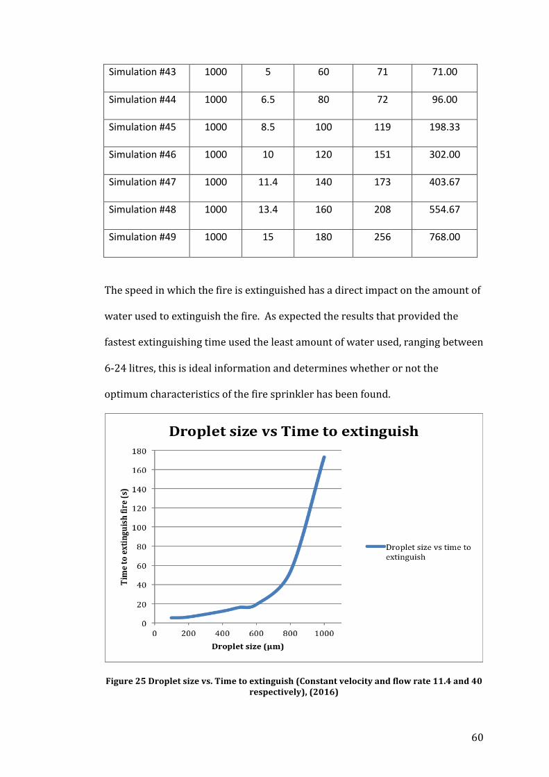
60
Simulation #43 1000 5 60 71 71.00
Simulation #44 1000 6.5 80 72 96.00
Simulation #45 1000 8.5 100 119 198.33
Simulation #46 1000 10 120 151 302.00
Simulation #47 1000 11.4 140 173 403.67
Simulation #48 1000 13.4 160 208 554.67
Simulation #49 1000 15 180 256 768.00
The speed in which the fire is extinguished has a direct impact on the amount of
water used to extinguish the fire. As expected the results that provided the
fastest extinguishing time used the least amount of water used, ranging between
6-‐24 litres, this is ideal information and determines whether or not the
optimum characteristics of the fire sprinkler has been found.
Figure 25 Droplet size vs. Time to extinguish (Constant velocity and flow rate 11.4 and 40 respectively), (2016)
61
10.2 Optimization
The fastest time to extinguish the fire was simulation #5 with a droplet
diameter of 100μm, velocity of 11.4 m/s and a flow rate of 140 L/min but the
simulation that used the least amount of water was simulation #8 with 6 litres
of water. Despite results showing a relatively quick time to extinguish the fire
and a low amount of water used, there is room for optimization. Ideally the best
characteristics would use the least amount of water and have the fastest time to
extinguish. To achieve this the simulations that had the fastest time to
extinguish and used the least amount of water (simulations #1-‐8) will be
optimized.
To optimize the simulations with the intention on receiving improved results a
tighter spray angle will be selected to ensure that the there is an adequate spray
coverage over the fire and to prevent a large amount of water being distributed
on the surroundings. Previously the spray angle was 30, 80 but now will be
20,70.
The results of the optimized simulations are shown below.
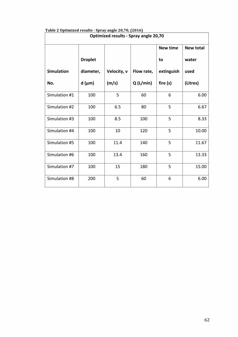
62
Table 2 Optimized results -‐ Spray angle 20,70, (2016) Optimized results -‐ Spray angle 20,70
Simulation
No.
Droplet
diameter,
d (μm)
Velocity, v
(m/s)
Flow rate,
Q (L/min)
New time
to
extinguish
fire (s)
New total
water
used
(Litres)
Simulation #1 100 5 60 6 6.00
Simulation #2 100 6.5 80 5 6.67
Simulation #3 100 8.5 100 5 8.33
Simulation #4 100 10 120 5 10.00
Simulation #5 100 11.4 140 5 11.67
Simulation #6 100 13.4 160 5 13.33
Simulation #7 100 15 180 5 15.00
Simulation #8 200 5 60 6 6.00
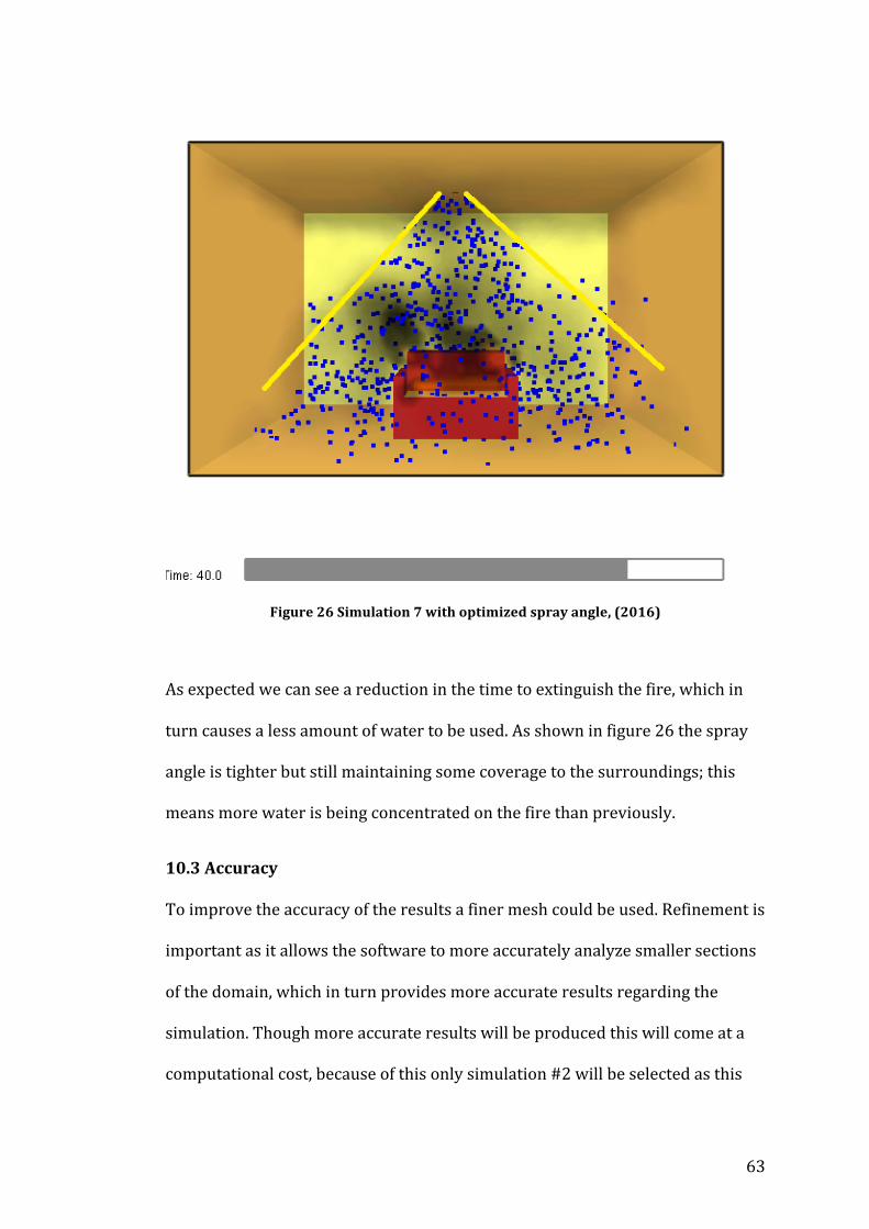
63
Figure 26 Simulation 7 with optimized spray angle, (2016)
As expected we can see a reduction in the time to extinguish the fire, which in
turn causes a less amount of water to be used. As shown in figure 26 the spray
angle is tighter but still maintaining some coverage to the surroundings; this
means more water is being concentrated on the fire than previously.
10.3 Accuracy
To improve the accuracy of the results a finer mesh could be used. Refinement is
important as it allows the software to more accurately analyze smaller sections
of the domain, which in turn provides more accurate results regarding the
simulation. Though more accurate results will be produced this will come at a
computational cost, because of this only simulation #2 will be selected as this
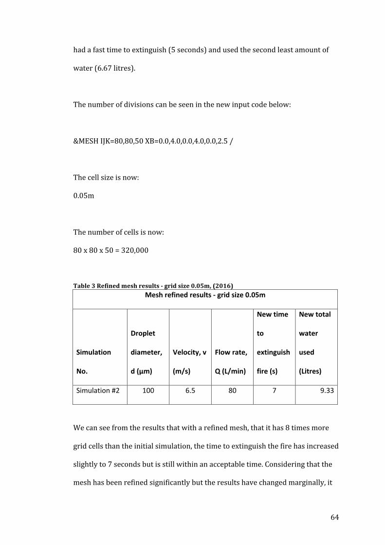
64
had a fast time to extinguish (5 seconds) and used the second least amount of
water (6.67 litres).
The number of divisions can be seen in the new input code below:
&MESH IJK=80,80,50 XB=0.0,4.0,0.0,4.0,0.0,2.5 /
The cell size is now:
0.05m
The number of cells is now:
80 x 80 x 50 = 320,000
Table 3 Refined mesh results -‐ grid size 0.05m, (2016) Mesh refined results -‐ grid size 0.05m
Simulation
No.
Droplet
diameter,
d (μm)
Velocity, v
(m/s)
Flow rate,
Q (L/min)
New time
to
extinguish
fire (s)
New total
water
used
(Litres)
Simulation #2 100 6.5 80 7 9.33
We can see from the results that with a refined mesh, that it has 8 times more
grid cells than the initial simulation, the time to extinguish the fire has increased
slightly to 7 seconds but is still within an acceptable time. Considering that the
mesh has been refined significantly but the results have changed marginally, it
65
can be said that mesh independency has been achieved; therefore the results
will not change anymore with a finer mesh.
Due to the fact that a finer mesh is used, more accurate results are provided
these results can be deemed as reliable. The results from the initial simulations
to the simulations with a finer mesh all show that the optimum sprinkler spray
characteristics are sprinklers with small droplet diameters and with a low to
medium velocity and flow rate in domestic premises.
10.4 Discussion
All simulations ran show that having small droplet sizes and having a low to
medium velocity and flow rate is key in extinguishing a fire. The spray angle was
critical in this scenario as the study focused on a sofa in the centre of a room; in
a real life scenario combustible items may be spread in any particular way
around a room and it may become more essential to have a wider spray angle.
As demonstrated in table 1 the selection of increasing droplet sizes (with flow
rate and velocity remaining constant), ranging from 100 to 1000μm, showed a
large increase in time to extinguish the fire between the minimum and
maximum sizes. In comparison, when the droplet size is kept at a constant, with
flow rate and velocity increasing, the change in time to extinguish the fire is not
as large. This shows that droplet size was the dominant characteristic as it made
the biggest difference.
To further support the results from this study a wide range of simulations
would have been run which would include a variety of different characteristics,
66
that are not limited to a maximum velocity of 15m/s and a maximum flow rate
of 180 L/min (minimum velocity and flow rate cannot be below 5m/s and
60L/min respectively as British Standard BS9251: 2005 5.2.5.1 dictate).
Additionally these simulations could be run with fires that have a variety of
different heat release rate values, these values would be taken from objects
within a domestic premise.
To further improve the accuracy of the results all the simulations could have
been run with a fine mesh opposed to a coarse or medium mesh although this
will result in an increase in computational cost.
Another way to provide improved results is to create a more realistic fire
scenario that is a true representation of an average UK room at risk of fire
including more combustible items, such as several sofas, carpet, curtain etc. This
would complicate the study as several separate heat release rates will have to
be included as well as a fire spread phenomena and different fire behaviours to
be considered. In turn this will have an effect on what the optimum sprinkler
spray characteristics should be and several fire sprinklers may have to be
involved opposed to just one.
Another way to support the results of this study is to compare them with
experimental data. This experimental data would consist of a real life fire
scenario, which replicates the simulations i.e. a room with a single burning sofa.
The optimum characteristics of the fire sprinkler would be tested in this setting.
It should be noted that this method would only be used to support already

67
gathered data and it would be unrealistic to calculate the optimum
characteristics for every domestic premise as there would be a range of
circumstances that would affect the characteristics i.e. different orientation and
different combustible items which result in different heat release rates.
Finally another way to support and improve the accuracy of results gathered is
to investigate how adjusting other characteristics and parameters of the fire
sprinkler system can affect the time to extinguish i.e. RTI, frangible bulb
activation temperatures, sprinkler head, sprinkler offset and allowing FDS to
increase the heat release rate over time, which replicates real life. Although
individually these characteristics may not be deemed as key characteristics,
combined they would provide important information and improved results. In
addition to this altering the ambient conditions may have an affect on the
results.
It should be noted that the results of this study do not reflect what the key
sprinkler spray characteristics should be in all living rooms within the UK, in
order to gather very accurate results, the domain and conditions should
replicate the real life scenario as much as possible.
11.0 Conclusion
Although there has been a significant reduction in fire related deaths in Britain
over the last 50 years, there is still a large amount of fire related deaths
occurring on a yearly basis. This study shows the importance of implementing a
fire sprinkler system in a domestic premise and how the implementation can
68
occur by analyzing rooms within a domestic premise that are at most risk of
having a fire. After the analysis the key characteristics the fire sprinkler needed
to extinguish such fires would need to be determined. By doing this there can
be an even larger reduction in fire related deaths with the possibility of
eliminating them completely.
This project shows that fires in domestic premises could be extinguished within
seconds if the key characteristics of a fire sprinkler system, namely droplet
sizes, flow rate, velocity and spray angle are appropriately selected. This project
shows that the optimum droplet sizes should be on the small end of the water
spray scale, 100-‐200μm and the velocity and corresponding flow rate is
dependent on the spray angle, a tight spray angle (slightly larger than fire area)
on the fire would perform better with a high flow rate and a wider spray angle
(considerably larger than fire area) would perform better with a low to medium
flow rate. With the optimum values selected it will be seen that a fire can be
extinguished before the maximum heat release rate is achieved and can also
prevent fire spread and fire growth from occurring.
Hopefully in the future we can see progression for the implementation of fire
sprinklers in homes, this would save hundreds of lives and in the long term
would be cost effective.

69
12.0 Bibliography
Bete. (2014). Spray Nozzles for Fire Extinguishing Systems. Available:
http://www.bete.co.uk/spray-‐nozzle-‐applications/fire-‐protection/droplet-‐size-‐
and-‐variation. Last accessed 18th March 2016
Day-‐Impex Ltd. (2015). Sprinkler bulbs. Available: http://www.day-‐
impex.co.uk/sprinkler-‐bulbs.html. Last accessed 18th March 2016.
Emmons, H.W.. (1992). The Ceiling Jet In Fires. Available:
http://www.iafss.org/publications/fss/3/249. Last accessed 18th March 2016.
Henry, G. (2014). Housing Minister Carl Sargeant backs controversial sprinkler
regulations in homes after Quebec care home tragedy. Available:
http://www.walesonline.co.uk/news/wales-‐news/housing-‐minister-‐carl-‐
sargeant-‐backs-‐6645433 . Last accessed 18th March 2016.
Ochshorn, J. (2014). Fire safety overview, sprinklers. Available:
https://courses.cit.cornell.edu/arch262/notes/02b.html. Last accessed 18th
March 2016.
Sze, C.K. (2009). International journal of engineering performance-‐based fire
codes. Response time index of sprinklers. 1 (1), p1-‐5.
Victaulic. (2014). FireLock K11.1. Available:
http://static.victaulic.com/assets/uploads/literature/40.20.pdf. Last accessed
18th March 2016.
70
13.0 References
Bourque, M. J & Svirsky, T.A. (2013). Computational modeling of fire sprinkler
spray characteristics using the fire dynamics simulator. Available:
https://m.wpi.edu/Pubs/E-‐project/Available/E-‐project-‐042213-‐
113716/unrestricted/Final_Report_4-‐24.pdf. Last accessed 18th March 2016.
British Standard. (2005). Sprinkler systems for residential and domestic
occupancies -‐ code of practice. Available: http://www.fire-‐sprinkler.co.uk/wp-‐
content/uploads/2011/09/BS%209251-‐2005.pdf. Last accessed 18th March
2016.
Davies, C. (2013). Why don't homes have sprinkler systems? Available:
http://www.bbc.co.uk/news/uk-‐politics-‐22271677. Last accessed 29th March
2016.
Department for Communities and Local Government. (2015). Fire statistics
Great Britain. Available: https://www.gov.uk/government/collections/fire-‐
statistics-‐great-‐britain. Last accessed 21st November 2015.
Dr. Kam Kenn Jhun. (2015). Building Services. Available:
http://www.slideshare.net/ZIyeeTan/building-‐servicesreport. Last accessed
21st November 2015.
71
Elite fire team. (2013). Back to Basics with the Fire Triangle. Available:
http://www.elitefire.co.uk/news/basics-‐fire-‐triangle/. Last accessed 21st
November 2015.
Fire equipment manufacturer's association. (2015). Types of fires. Available:
http://www.femalifesafety.org/types-‐of-‐fires.html. Last accessed 21st
November 2015.
Fisher, D. (2010). How fire sprinklers work. Available:
http://home.howstuffworks.com/home-‐improvement/household-‐
safety/fire/fire-‐sprinker-‐system4.htm. Last accessed 21st November 2015.
Forney, G. P (2015). Smokeview, a tool for visualizing Fire Dynamics Simulation
Data. 6th ed. U.S.A: NIST Special publication 1017-‐1. p25-‐26.
Grant, G., Brenton, J., Drysdale, D. “Fire Suppression by Water Sprays”, Progress
in Energy and Combustion Science, Vol 26, p. 83, 85-‐89, 2000.
Hamins, A. (1992). Characteristics of pool fire burning. Building and fire
research laboratory . 1 (1), p1-‐6, 15.
Health and safety executive. (2016). Jet fires. Available:
http://www.hse.gov.uk/offshore/strategy/jet.htm. Last accessed 5th Dec 2015.
72
Health and safety executive. (2016). Pool fires. Available:
http://www.hse.gov.uk/offshore/strategy/pool.htm. Last accessed 5th Dec
2015.
Incendia Consulting. (2016). A history of sprinkler development. Available:
http://incendiaconsulting.com/History%20of%20Sprinkler%20Development.p
df. Last accessed 21st November 2015.
Kim, Hyeong-‐Jin and David G. Lilley. "Heat Release Rates of Burning Items in
Fires." AIAA 2000-‐0722. 38th Aerospace Sciences Meeting & Exhibit. P1-‐6 & 15.
Reno, NV. January 2000.
Madrzykowski, D Fleming, R.P. (2008). Residential Sprinkler Systems. Fire
Protection Handbook. 20th (1), p91-‐106.
Marshall, A.W & Di Marzo, M. (2014). Modelling aspects of sprinkler spray
dynamics in fires. Process safety and environmental protection. 1 (1), p97-‐104.
McGratten, K (2015). Fire Dynamics Simulator User's Guide. 6th ed. U.S.A: NIST
Special Publication 1019. p3-‐6.
NASA. (2015). Navier-‐Stokes Equations. Available:
https://www.grc.nasa.gov/www/k-‐12/airplane/nseqs.html. Last accessed 7th
April 2016.
73
NIST. (2015). Fire on the web. Available:
http://fire.nist.gov/bfrlpubs/fire08/PDF/f08007.pdf. Last accessed 18th March
2016.
Rodriguez, J. (2015 ). Types of fires and how to recognize them. Available:
http://blog.sdfirealarms.co.uk/fire-‐safety/types-‐fires/. Last accessed 5th Dec
2015.
Science learn. (2009). Fire behaviour. Available:
http://sciencelearn.org.nz/Contexts/Fire/Science-‐Ideas-‐and-‐Concepts/Fire-‐
behaviour. Last accessed 5th Dec 2015.
Science learn. (2009). What is fire?. Available:
http://sciencelearn.org.nz/Contexts/Fire/Science-‐Ideas-‐and-‐Concepts/What-‐
is-‐fire. Last accessed 5th Dec 2015.
Sheppard, D. (2002). Spray characteristics of fire sprinklers. Building and fire
research laboratory . 1 (1), p6-‐201.
Tyco Fire and Integrated Solutions. (2016). Fire Sprinklers. Available:
http://www.tycofis.co.uk/products/Fire-‐Sprinklers/fire-‐sprinklers. Last
accessed 18th March 2016.
Tyco Fire and Integrated Solutions. (2016). Water Spray. Available:
http://www.tycofis.co.uk/products/Water-‐Spray/water-‐spray. Last accessed

74
18th March 2016.
Tyco Fire and Integrated Solutions. (2016). Watermist. Available:
http://www.tycofis.co.uk/products/WaterMist/watermist. Last accessed 18th
March 2016.
Woodford, C. (2016). Fire sprinklers . Available:
http://www.explainthatstuff.com/firesprinklers.html. Last accessed 21st
November 2015.
Yao, C. (2015). Fire safety science. Overview of sprinkler technology research. 1
(1), 93-‐108.

75
14.0 Appendices
14.1 FDS simulation input file
FDS code for living
Study of sprinkler spray characteristics in domestic premises.
&HEAD CHID='living_room', TITLE='Domain Creation'/
*Domain dimension, 4 x 4 x 2.5 m, cell dimensions, 0.1 x 0.1 x 0.1 m, 40,000 cells
&MESH IJK=40,40,25 XB=0.0,4.0,0.0,4.0,0.0,2.5 /
*Run time of simulation is set to zero to allow quick checking of geometry
&TIME T_END=60.0 /
*Defines evaporating liquid droplets as water, providing the thermal properties,
radiation absorption and coloured blue in smokeview
&SPEC ID='WATER VAPOR' /
&PART ID='water drops', SPEC_ID='WATER VAPOR', DIAMETER=<value> /
*Adds a sprinkler within the computational domain and specifies characteristics
of the sprinkler
&PROP ID='K-‐11', QUANTITY='SPRINKLER LINK TEMPERATURE', RTI=100,
ACTIVATION_TEMPERATURE=79, OFFSET=0.10, PART_ID='water drops',
PARTICLE_VELOCITY=<value>, SPRAY_ANGLE=30.,80., FLOW_RATE=<value> /
&DEVC XYZ=2.0,2.0,2.5, PROP_ID='K-‐11', ID='Spr_1' /
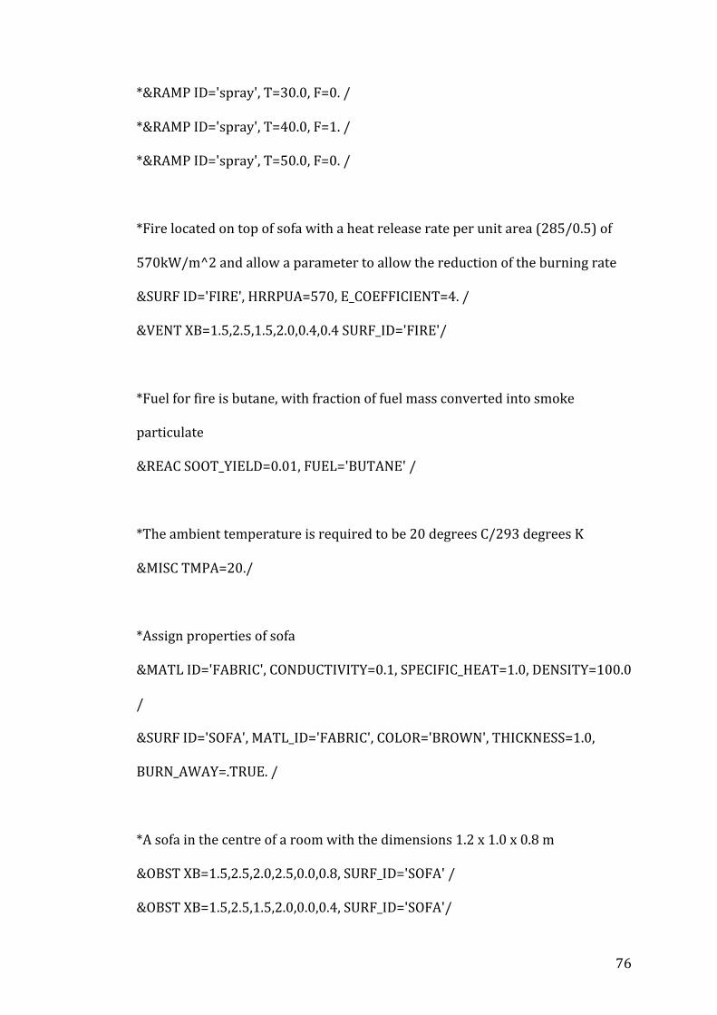
76
*&RAMP ID='spray', T=30.0, F=0. /
*&RAMP ID='spray', T=40.0, F=1. /
*&RAMP ID='spray', T=50.0, F=0. /
*Fire located on top of sofa with a heat release rate per unit area (285/0.5) of
570kW/m^2 and allow a parameter to allow the reduction of the burning rate
&SURF ID='FIRE', HRRPUA=570, E_COEFFICIENT=4. /
&VENT XB=1.5,2.5,1.5,2.0,0.4,0.4 SURF_ID='FIRE'/
*Fuel for fire is butane, with fraction of fuel mass converted into smoke
particulate
&REAC SOOT_YIELD=0.01, FUEL='BUTANE' /
*The ambient temperature is required to be 20 degrees C/293 degrees K
&MISC TMPA=20./
*Assign properties of sofa
&MATL ID='FABRIC', CONDUCTIVITY=0.1, SPECIFIC_HEAT=1.0, DENSITY=100.0
/
&SURF ID='SOFA', MATL_ID='FABRIC', COLOR='BROWN', THICKNESS=1.0,
BURN_AWAY=.TRUE. /
*A sofa in the centre of a room with the dimensions 1.2 x 1.0 x 0.8 m
&OBST XB=1.5,2.5,2.0,2.5,0.0,0.8, SURF_ID='SOFA' /
&OBST XB=1.5,2.5,1.5,2.0,0.0,0.4, SURF_ID='SOFA'/
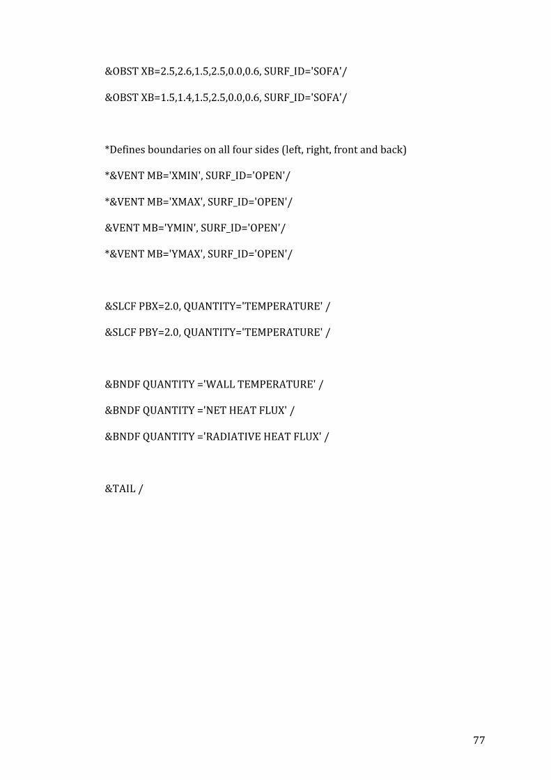
77
&OBST XB=2.5,2.6,1.5,2.5,0.0,0.6, SURF_ID='SOFA'/
&OBST XB=1.5,1.4,1.5,2.5,0.0,0.6, SURF_ID='SOFA'/
*Defines boundaries on all four sides (left, right, front and back)
*&VENT MB='XMIN', SURF_ID='OPEN'/
*&VENT MB='XMAX', SURF_ID='OPEN'/
&VENT MB='YMIN', SURF_ID='OPEN'/
*&VENT MB='YMAX', SURF_ID='OPEN'/
&SLCF PBX=2.0, QUANTITY='TEMPERATURE' /
&SLCF PBY=2.0, QUANTITY='TEMPERATURE' /
&BNDF QUANTITY ='WALL TEMPERATURE' /
&BNDF QUANTITY ='NET HEAT FLUX' /
&BNDF QUANTITY ='RADIATIVE HEAT FLUX' /
&TAIL /
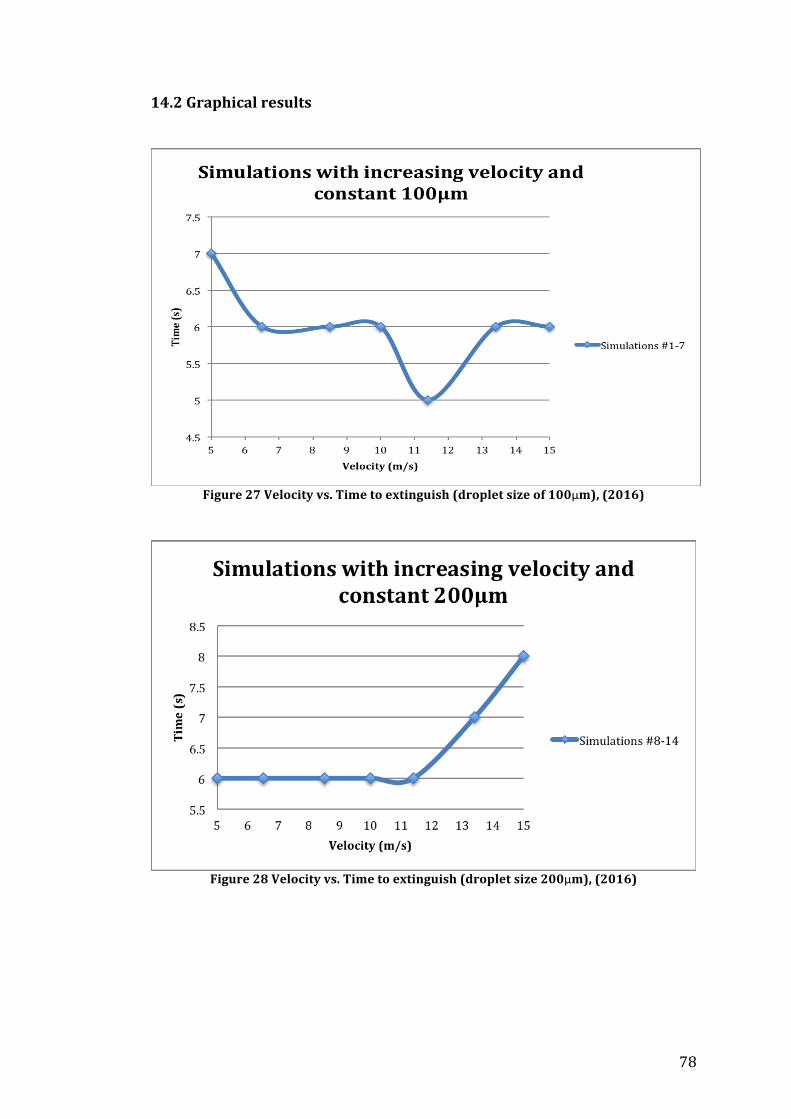
78
14.2 Graphical results
Figure 27 Velocity vs. Time to extinguish (droplet size of 100μm), (2016)
Figure 28 Velocity vs. Time to extinguish (droplet size 200μm), (2016)

79
Figure 29 Velocity vs. Time to extinguish (droplet size 400μm), (2016)
Figure 30 Velocity vs Time to extinguish (droplet size 500μm), (2016)
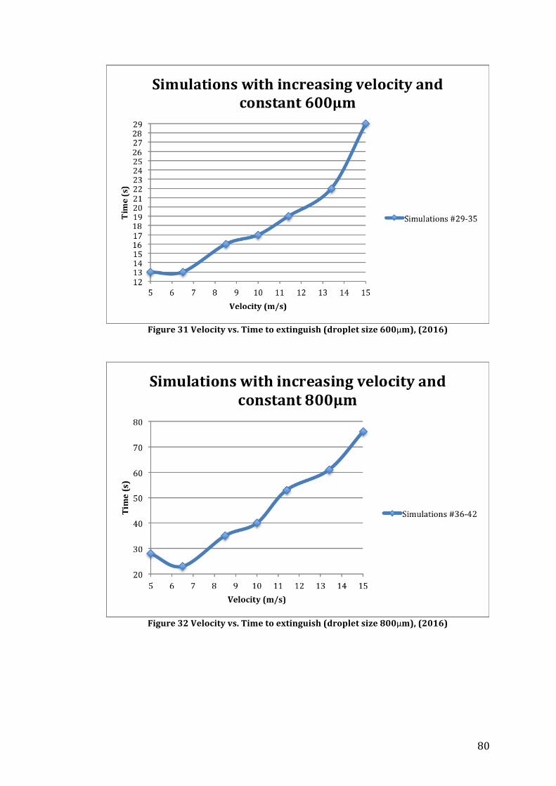
80
Figure 31 Velocity vs. Time to extinguish (droplet size 600μm), (2016)
Figure 32 Velocity vs. Time to extinguish (droplet size 800μm), (2016)

81
Figure 33 Velocity vs. Time to extinguish (droplet size 1000μm), (2016)
14.3 Navier-‐Stokes equations
Figure 34 Navier-‐Stokes equations (NASA, 2016)
Top Related