


Languages
Pages
Legal


Disconnectable Turret Mooring Systems for Deep Water
2006 ISOPE San Francisco, California
May 30, 2006
Arun Duggal, Sam Ryu, and Caspar Heyl
R&D, FMC Technologies Floating Systems

2/29
Co-authors at FMC Floating Systems
Arun Duggal
Sam Ryu
Caspar Heyl

3/29
Hurricane Katrina
With the large number of hurricanes in the GOM the DTM concept is being looked at with strong interest
Source: World Oil / Nov. 2005

4/29
1. Buoy Disconnect3. Buoy Reconnect
2. Disconnected

5/29
Introduction
• Disconnectable turret mooring systems being in use since late 1980’s offshore Australia and SE Asia
• Two disconnectable systems off the Grand Banks to avoid Icebergs.
• Excellent history of performance in both SC sea and Australia
• JHN system installed in 1993 has disconnected over 20 times
• MODEC/FMC currently building the first deepwater disconnectable system for Stybarrow

6/29
Existing Disconnectable Turret Mooring Systems
• JHN Lufeng 13-1, South China Sea
• 20 disconnects in 13 yrs
• Terra NovaCanada
• Santos Ltd – MV11Mutineer-Exeter Australia
• 5 disconnects in year 2006

7/29
Cyclones around Australia
Research has shown that cyclones in the Australian region exhibit more erratic paths than cyclones in other parts of the world. A tropical cyclone can last for a few days or up to two or three weeks. Movement in any direction is possible including sharp turns and even loops.
Reference: Australian Government, Bureau of Meteorology http://www.bom.gov.au/info/cyclone/#severity
Stybarrow Field
MV11 @ Mutineer/Exeter Field

8/29
Cyclones over Mutineer/Exeter Field
Name Period Max Category
• Clare Jan 7-10 2006 3
• Daryl Jan 18-23 2006 2
• Emma Feb 27-28 2006 1
• Floyd March 21-26 2006 4
• Glenda March 27-31 2006 5
• Hubert April 6-7 2006 2

9/29
Cyclone Phase Boundaries
M = (K + N) x V
Example) A category 3 cyclone moving at 10 knots,time required to sail to safe area is 12 hours.M = ( 20 + 12 ) x 10 = 320
Blue = 1.5 M = 480 nautical miles = 890kmYellow = 1.25 M = 400 nautical miles = 740kmRed = 0.75 M = 240 nautical miles = 440km
245
224
203
162
121
10Tropical Low
KCategory
Blue
YellowRed
1.5M
1.25M
0.75M
FPSO

10/29
Emergency Procedures
• BlueA plan for preparation for disconnection
A ballast plan
A plan for evacuating non-essential personnel
• YellowShutdown production
Prepare to disconnect from DTM
Proceed with ballast plan
• RedDisconnect from DTM

11/29
Safety Case
• A 12 hour period for shutting down production and preparing the FPSO is included in the definition of Cyclone / Storm alert phases.
• Preparations for disconnect commence when a Yellow AlertYellow Alert is declared. Notwithstanding this, the OIM may raise alerts and implement relevant alert procedures at any time.
• The decision to disconnect is made by the Master / Operations Supervisor.

12/29
Clare
2AM Jan 8 Shut-in production
9PM Jan 8 Lowered all risers
2AM Jan 9 Disconnected
Jan 10 Back to Field
7AM Jan 11 Picked up Spider Buoy line3PM Jan 11 Commenced Riser pickup4PM Jan 12 Started production
Under Construction: Boundary radii and sail-away course to be informed by MV11

13/29
Stybarrow FPSO SystemDisconnectable Turret Mooring System

14/29
• BHP Billiton Petroleum Pty. Ltd. (Client
• Stybarrow Field, Southern CarnarvonBasin, Australia
• 150,000 dwt FPSO Stybarrow Venture MV16
• Water depth 2,706-feet (825m)
• Installaltion planned for 2008
Stybarrow Venture MV16 Disconnectable Internal Turret Mooring

15/29
Global Analysis Basic Design Basis
• FPSO to disconnect from mooring and risers to avoid cyclones
• FPSO to stay on station during the 100-year non Cyclonic (winter) storm
• 12 risers and umbilicals
• 15 year design Life
• Mooring system design– maintain adequate offsets for riser system
– optimize mooring, riser and spider buoy system to meet spider buoy and turret requirements

16/29
Stybarrow FPSO Vessel Particulars
PROFILE
F.S . : 800 W.S . : 4800
B .L.
(11.20 m) (34.40 m) (43 .20 m) (50.00 m) (83 .60 m) (117.20 m) (150.80 m)
FR76+0.4
(184 .40 m) (218.00 m) (251.60 m) (264.00 m)
W.S . : 4800 F.S . : 800
F.W.T.(P& S)S TEE RINGGEA R RM.
A.P.T.(C)R.T.
S .L.W.L.
ENGINE ROOM
P UMPROOME NT.
PUMP ROOM
SLOP T. (P&S)
NO.6 W. B. T. (P
&S)
NO.6 C.O.T.(P&S)
NO.5 W. B
. T. (P&S)
NO.5 C.O.T.(P&S)
NO.4 W. B
. T. (P&S)
NO.4 C.O.T.(P&S)
NO.3 W. B
. T. (P&S)
NO.3 C.O.T.(P&S)
NO.2 W. B
. T. (P&S)
NO.2 C.O.T.(P&S)
NO.1 W. B
. T. (P&S)
F.P.T.
(C)
C.L.
S .L.W.L.NO.1 C.O.T.(P&S)
C.W.T. (C)
B .L.
11200 23200 4000 4800 6800
F.S . :850
W.S . :3400
33600 33600 33600 33600 33600 33600 12400
Cofferdam(P
&S)
VOID(C)
M.D.O.T.(P&S)
B .W.
B/S &S tandby .F.P.R.
F.P.120110100959080 857570656040 50302010A .P.
63m≈
264m
• Newbuild vessel
– LBP = 264m, Beam = 48m, Depth = 23.2m
– Maximum Displacement = 181,000 MT
• Turret Location:110m forward of midship
• Bilge Keels: 115m long, 0.8 m wide
• Main Propulsion and Rudder
• Stern thruster for heading control during some operations

17/29
Turret Structure
• Swivel Access Structure
• Swivel Stack
• Manifold Piping
• Upper Turret Structure
• Riser Deck
• Bearing
• Turret Shaft
• Chain Support Assembly
• Anchor Legs
18/29
Things to be considered…
• Buoy Disconnect from FPSO
• Disconnected Buoy Motions
• Buoy Reconnect Analysis
19/29
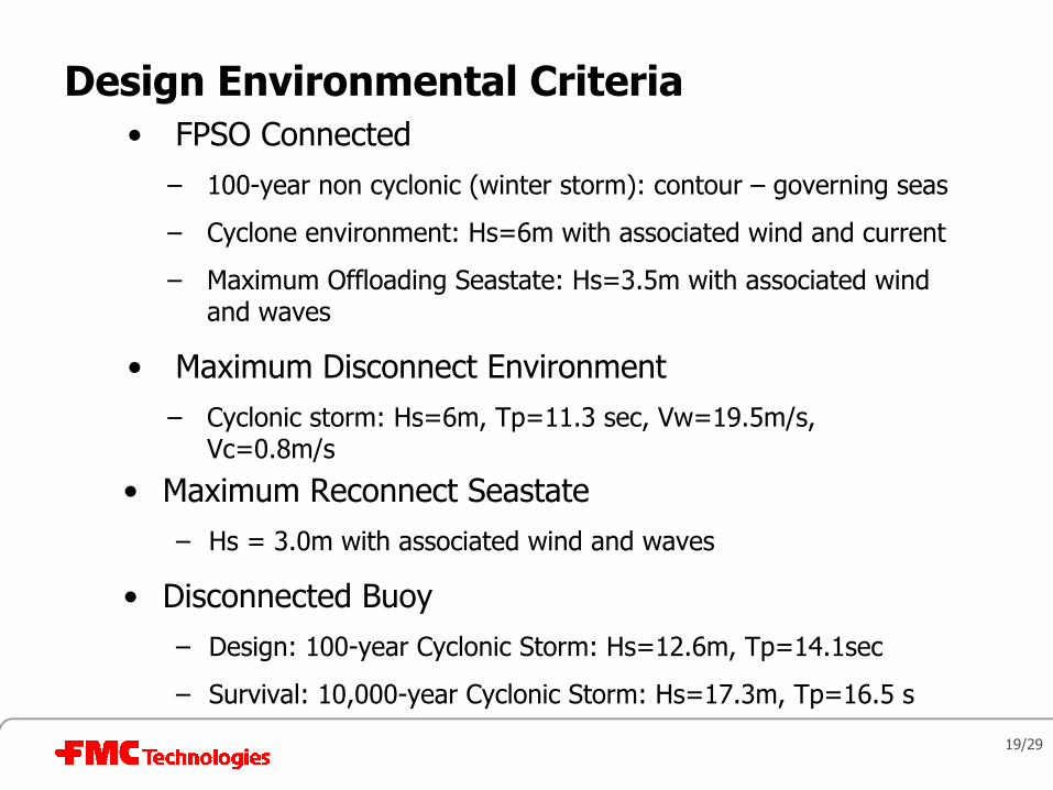
Design Environmental Criteria• FPSO Connected
– 100-year non cyclonic (winter storm): contour – governing seas
– Cyclone environment: Hs=6m with associated wind and current
– Maximum Offloading Seastate: Hs=3.5m with associated wind and waves
• Maximum Disconnect Environment– Cyclonic storm: Hs=6m, Tp=11.3 sec, Vw=19.5m/s,
Vc=0.8m/s
• Maximum Reconnect Seastate– Hs = 3.0m with associated wind and waves
• Disconnected Buoy – Design: 100-year Cyclonic Storm: Hs=12.6m, Tp=14.1sec
– Survival: 10,000-year Cyclonic Storm: Hs=17.3m, Tp=16.5 s

20/29
Spider Buoy Particulars• Maximum Diameter: 14 m
• Height: ~14.7 m
• Estimated Displacement
• Estimated Weight
• Design Net Buoyancy (mooring and risers)
– Riser Payload
– Mooring Payload
– Total MG load included in above
– Spider Buoy MG load
• Water Ballast System for controlling net buoyancy
• Design Depth Static (to top of buoy) = 30 m
• Maximum Design Depth (bottom) = 90 m

21/29
Spider Buoy Drop Test
22/29
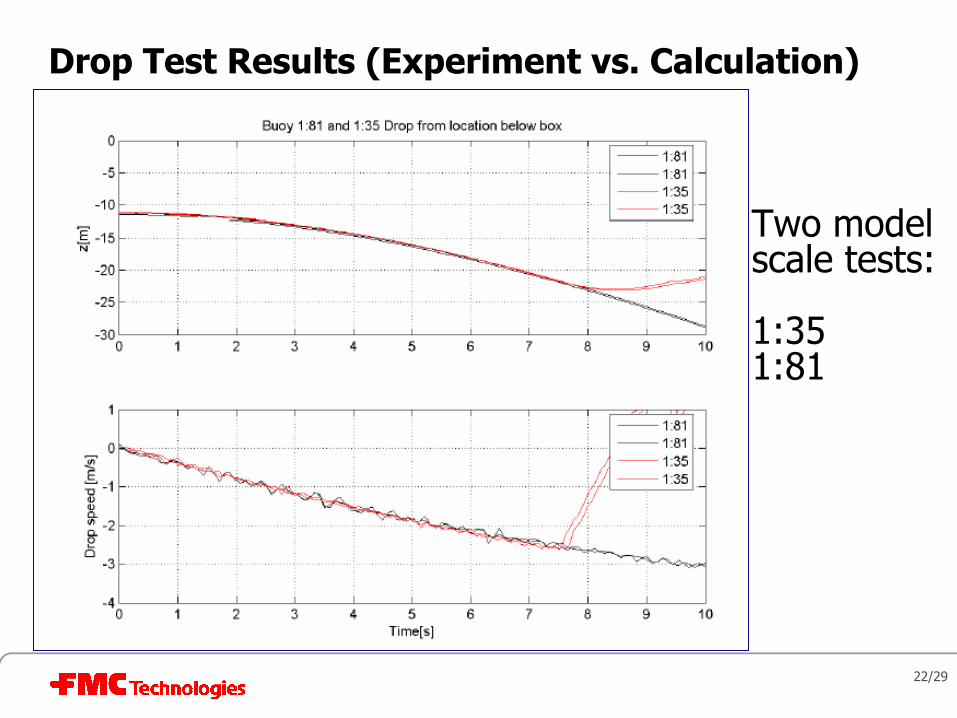
Drop Test Results (Experiment vs. Calculation)
Two model scale tests:
1:351:81

23/29
Spider Buoy Motion Characteristics (Cd & Cm)
• disconnected buoy design– 100-year cyclonic storm
– Hs=12.6m
– Tp=14.1sec
• regular wave case:– 100yr cyclonic collinear
– H=20.9 m
– T=12.9 sec
– Vc=2.1 m/s (current)

24/29
Spider Buoy Motion Characteristics (Cd & Cm)
• inertia and drag coeffs.
– Cd_n=1.0
– Cd_a=0.9
– Cm=0.60

25/29
Simulation of Buoy Pull-in Loads
OrcaFlex 8.6a: sb027.sim (modified 7:45 AM on 10/18/2005 by OrcaFlex
Time (s)6004002000
FPSO
X (m
)
-125
-130
-135
-140
-145
-150
-155
OrcaFlex 8.6a: sb027.sim (modified 7:45 AM on 10/18/2005 by OrcaFlex
Time (s)6004002000
Upd
ated
Spide
r Buo
y Z (m
)
-10
-15
-20
-25
-30
-35
OrcaFlex 8.6a: sb027.sim (modified 7:45 AM on 10/18/2005 by OrcaFlex
Time (s)6004002000
fender Effective Te
nsion (kN) at End A
2500
2000
1500
1000
500
0

26/29
1. Buoy Disconnect3. Buoy Reconnect
2. Disconnected

27/29
Final Remarks (1/2)
• Disconnectable Turret Moorings are proven technology for mooring FPSOs in Hurricane environments
• DTMs in Deepwater have a number of challenges
• Trade-off between buoyancy on riser system and spider buoy
• Spider Buoy ballasting analysis / design along with riser model/installation plans
• Riser contents density variations have large impact on spider buoy payload requires SB with adjustable buoyancy (+/- 30% of average load)

28/29
Final Remarks (2/2)
• Can also be mitigated by adopting hybrid tower risers with individual support buoys
• Presentation showed ability of analysis to model complex operations like disconnect, disconnected buoy response in 100-year typhoon seas, and reconnection
• Design of riser system cannot be independent of turret – in fact riser design needs to be optimized with turret for best overall solution.

29/29
Disconnectable Turret Mooring Systems for Deep Water
Arun Duggal, Sam Ryu, and Caspar Heyl
[arun.duggal, sam.ryu, caspar.heyl]@fmcti.com
R&D, FMC Technologies Floating Systems
Top Related