


Languages
Pages
Legal


Meridian 1
Digital Telephones Line Engineering
Document Number: 553-2201-180Document Release: Standard 5.00Date: January 2002
Year Publish FCC TM
Copyright © 1989–2002 Nortel NetworksAll Rights Reserved
Printed in Canada
Information is subject to change without notice. Nortel Networks reserves the right to make changes in design or components as progress in engineering and manufacturing may warrant. This equipment has been tested and found to comply with the limits for a Class A digital device pursuant to Part 15 of the FCC rules, and the radio interference regulations of Industry Canada. These limits are designed to provide reasonable protection against harmful interference when the equipment is operated in a commercial environment. This equipment generates, uses and can radiate radio frequency energy, and if not installed and used in accordance with the instruction manual, may cause harmful interference to radio communications. Operation of this equipment in a residential area is likely to cause harmful interference in which case the user will be required to correct the interference at their own expense.
SL-1 and Meridian 1 are trademarks of Nortel Networks.


Page 3 of 36
4
Revision historyJanuary 2002
Standard 5.00. This document is up-issued to support Meridian 1 Release 25.40 systems.
April 2000Standard 4.00. This is a global document and is up-issued for X11 Release 25.0x.
December 1994Standard 3.00. Reissued to include editorial changes and indexing. Due to the extent of the changes, revision bars are not used.
December 1, 1991Standard 2.00. Reissued to include technical content updates. Due to the extent of the changes, revision bars are not used.
August 10, 1990Standard 1.00. Reissued for compliance with Northern Telecom standard 164.0.
Digital Telephones Line Engineering

Page 4 of 36
553-2201-180 Standard 5.00 January 2002

Page 5 of 36
6
Contents
About this document . . . . . . . . . . . . . . . . . . . . . . . 7
Engineer a telephone line . . . . . . . . . . . . . . . . . . . . 9
Select a loop . . . . . . . . . . . . . . . . . . . . . . . . . . . . . . 19
Calculate DC loop resistance . . . . . . . . . . . . . . . . . 21
Perform loop diagnostic tests . . . . . . . . . . . . . . . . 23
Measure impulse noise . . . . . . . . . . . . . . . . . . . . . . 25
Measure background noise . . . . . . . . . . . . . . . . . . 27
Calculate expected pulse loss . . . . . . . . . . . . . . . . 29
Measure DC loop resistance . . . . . . . . . . . . . . . . . 33
Index . . . . . . . . . . . . . . . . . . . . . . . . . . . . . . . . . . . . . 35
Digital Telephones Line Engineering
Page 6 of 36 Contents
553-2201-180 Standard 5.00 January 2002

Page 7 of 36
8
About this documentThis document applies to Meridian 1 Internet Enabled systems.
This document is a global document. Contact your system supplier or your Nortel Networks representative to verify that the hardware and software described is supported in your area.
Who should use this documentThis document is intended for individuals responsible for configuring digital telephone lines.
Digital Telephones Line Engineering

Page 8 of 36 About this document
553-2201-180 Standard 5.00 January 2002
Page 9 of 36
18
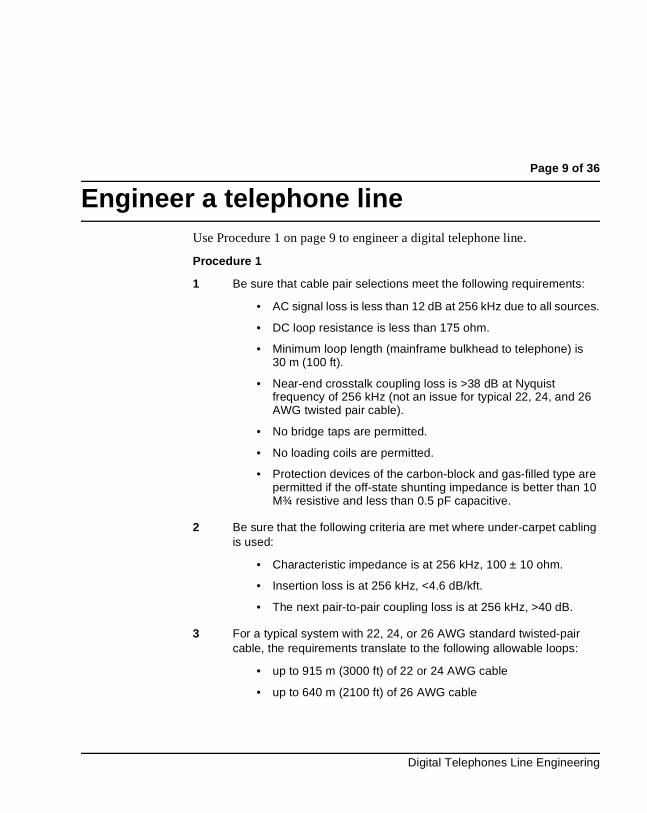
Engineer a telephone lineUse Procedure 1 on page 9 to engineer a digital telephone line.
Procedure 1
1 Be sure that cable pair selections meet the following requirements:
• AC signal loss is less than 12 dB at 256 kHz due to all sources.
• DC loop resistance is less than 175 ohm.
• Minimum loop length (mainframe bulkhead to telephone) is 30 m (100 ft).
• Near-end crosstalk coupling loss is >38 dB at Nyquist frequency of 256 kHz (not an issue for typical 22, 24, and 26 AWG twisted pair cable).
• No bridge taps are permitted.
• No loading coils are permitted.
• Protection devices of the carbon-block and gas-filled type are permitted if the off-state shunting impedance is better than 10 M¾ resistive and less than 0.5 pF capacitive.
2 Be sure that the following criteria are met where under-carpet cabling is used:
• Characteristic impedance is at 256 kHz, 100 ± 10 ohm.
• Insertion loss is at 256 kHz, <4.6 dB/kft.
• The next pair-to-pair coupling loss is at 256 kHz, >40 dB.
3 For a typical system with 22, 24, or 26 AWG standard twisted-pair cable, the requirements translate to the following allowable loops:
• up to 915 m (3000 ft) of 22 or 24 AWG cable
• up to 640 m (2100 ft) of 26 AWG cable
Digital Telephones Line Engineering

Page 10 of 36 Engineer a telephone line
4 If the selected cable pair does not work satisfactorily, select another cable pair as shown in Figure 1 on page 10.
Figure 1Engineer a telephone line (Part 1 of 8)
Select (another) loop that meets the criteria for cable length. (Procedure 2)
Is there another loop available?
Go toStep 1
Go to Step 5
[ 1 ]
[ 4 ]
[ 2 ]
[ 3 ]
Is there a bridge
tap?
No
Yes
Yes
No
Remove the bridge tap.
Go to Step 5
553-5935
553-2201-180 Standard 5.00 January 2002

Engineer a telephone line Page 11 of 36
Figure 1Engineer a telephone line (Part 2 of 8)
553-5936
Go toStep 9
Is the resistance less than 175 ohm?
[ 8 ]
[ 10 ]
[ 7 ]
Calculate the loopresistance.(Procedure 3)
Go toStep 1
Go to Step 12
No
No
Yes
Is the looplength less than
2.1 kft?
[ 5 ]
No
Yes
Is the PBX atthe central
office?
[ 9 ]
Yes
No
Go to Step 15
Repair the problem.
[ 11 ]
Go to Step 12
Is there any26 AWG cable in
the loop?
[ 6 ]
No
Yes
Step 9
Does the looppass the loop
diagnostic test?(Procedure 4)
No
Yes
Digital Telephones Line Engineering
Page 12 of 36 Engineer a telephone line
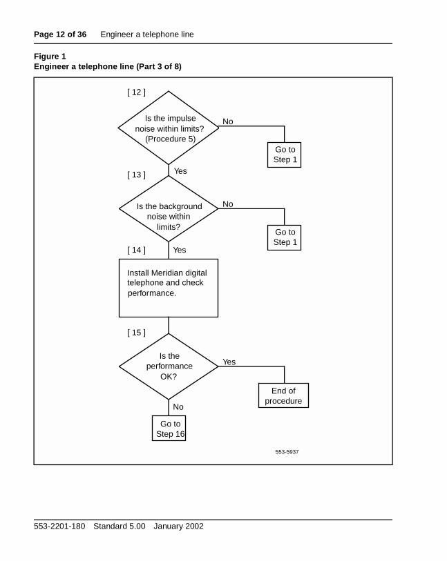
Figure 1Engineer a telephone line (Part 3 of 8)
Is the backgroundnoise within
limits?
[ 13 ]
[ 15 ]
[ 14 ]
Install Meridian digitaltelephone and checkperformance.
Go toStep 1
Go toStep 16
No
Yes
Is the impulsenoise within limits?
(Procedure 5)
[ 12 ]
No
Yes
Is theperformance
OK?
Go to Step 1
Yes
No
553-5937
End ofprocedure
553-2201-180 Standard 5.00 January 2002
Engineer a telephone line Page 13 of 36
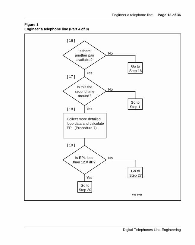
Figure 1Engineer a telephone line (Part 4 of 8)
553-5938
Is this thesecond time
around?
[ 17 ]
[ 19 ]
[ 18 ]
Collect more detailedloop data and calculate EPL (Procedure 7).
Go to Step 1
Go to Step 20
No
Yes
Is thereanother pairavailable?
[ 16 ]
No
Yes
Is EPL lessthan 12.0 dB?
Go toStep 18
No
Yes
Go to Step 27
Digital Telephones Line Engineering

Page 14 of 36 Engineer a telephone line
Figure 1Engineer a telephone line (Part 5 of 8)
553-5939
[ 20 ]
Go toStep 22
Install Meridian digital telephone and check performance if not already done.
Is theperformance
OK?
Are the loopdiagnostics and
noise measurementalready done?
Perform loop diagnostics and measurements. (Procedures 4, 5, and 6)
[ 21 ]
[ 22 ]
[ 23 ]Go to
Step 27
Go to Step 24
No
Yes
Yes
No
End ofprocedure
553-2201-180 Standard 5.00 January 2002

Engineer a telephone line Page 15 of 36
Figure 1Engineer a telephone line (Part 6 of 8)
553-5940
Is the problemfixed?
Is theperformance OK?
[ 25 ]
[ 26 ]
Go to Step 27
No
Yes
No
Yes
Are impulse noise and background noise
within limits?
[ 24 ]
Yes
No
Go to Step 27
Go to Step 27
End ofprocedure
Digital Telephones Line Engineering

Page 16 of 36 Engineer a telephone line
Figure 1Engineer a telephone line (Part 7 of 8)
553-5941
[ 27 ]
Measure the DC loop resistance. (Procedure 8)
Is the loopresistance less than
175 ohm?
[ 28 ]
Install new cable.
[ 29 ]
No
[ 30 ]
Go toStep 35
Measure loop insertion loss at 256 kHz.
Is the insertionloss less than
12.0 dB?
[ 31 ]
No
Go to Step 32
Yes
Yes
End ofprocedure
553-2201-180 Standard 5.00 January 2002
Engineer a telephone line Page 17 of 36
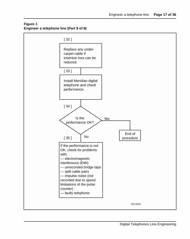
Figure 1Engineer a telephone line (Part 8 of 8)
553-5942
[ 32 ]
Replace any under-carpet cable if insertion loss can be reduced.
Install Meridian digital telephone and check performance.
[ 33 ]
[ 34 ]
Is theperformance OK?
If the performance is not OK, check for problems with:— electromagnetic interference (EMI)— unrecorded bridge taps— split cable pairs— impulse noise (not recorded due to speed limitations of the pulse counter)— faulty telephone
[ 35 ]
Yes
NoEnd of
procedure
Digital Telephones Line Engineering
Page 18 of 36 Engineer a telephone line
553-2201-180 Standard 5.00 January 2002

Page 19 of 36
20
Select a loopFor a Meridian digital telephone, the loop must be without bridge taps, less than 175 ohm DC resistance, and less than 12.0 dB loss at 256 kHz. For single-gauge 22 and 24 AWG cable, and D inside wiring, the length limit is 914.4 m (3000 ft). For single-gauge 26 AWG cable, the length limit is 640.08 m (2100 ft).
The allowable loop length assumes there is no under-carpet cable. If there is under-carpet cable that is a different type than Western Electric (WE) 4-pair cable, reduce the allowable loop length by using the following equation:
LM = [12 – (UC x UL)] /LL
where:
LM = loop length limit in km (kft) (excluding the length of the under-carpet cable)
LL = loop loss in dB/km (dB/kft) at 256 kHz
UC = length of the under-carpet cable in km (kft)
UL = loss of the under-carpet cable in dB/km (dB/kft) at 256 kHz (see Table 3, “Attenuation at 256 kHz for U/C cable,” on page 31 for dB values)
Digital Telephones Line Engineering

Page 20 of 36 Select a loop
553-2201-180 Standard 5.00 January 2002

Page 21 of 36
22
Calculate DC loop resistanceUse Procedure 2 on page 21 to calculate the DC loop resistance.
Procedure 2
1 Calculate the DC loop resistance by adding the resistance of each cable section. Calculate the resistance of each cable section by using the following formula (cable resistances are given in Table 1, “Conductor resistance per unit,” on page 22):
LRi = CRi x SLi
where:
LRi = DC resistance for cable section i
CRi = conductor resistance per unit length for the cable section i
SLi = length of cable section i
Digital Telephones Line Engineering

Page 22 of 36 Calculate DC loop resistance
2 Add the total of all cable sections. If the total of all sections exceeds 175 ohm, select another loop.
Note: The loop resistance limit of 175 ohm must be reduced by 1 ohm for each percent of the loop that is aerial cable (see Table 1, “Conductor resistance per unit,” on page 22).
Table 1Conductor resistance per unit
Gauge Ohm per loop kft Ohm per loop km
26 83 278
24 52 173
22 33 109
19 16 54
553-2201-180 Standard 5.00 January 2002

Page 23 of 36
24
Perform loop diagnostic testsThe following equipment is required for the loop diagnostic tests in Procedure 3 on page 23:
• one volt-ohmmeter (VOM) for each test
• one 77 cable analyzer or equivalent for each test
Procedure 3
Testing foreign voltage
1 Set the VOM range switch to a scale 60 V dc/V ac or greater.
2 Connect the VOM test probes to the loop at the line card or distributing frame.
3 Measure the DC and AC voltage between the following points under no-load conditions:
• tip (T) and ring (R)
• T and ground (GND)
• R and GND
Requirement: Voltage readings should be less than 1 V dc/V ac.
Testing insulation resistance
1 Set the VOM range switch to ohm x 10,000 and adjust the meter to zero.
2 Connect the VOM test probes to the loop at the line card or distribution frame.
Digital Telephones Line Engineering

Page 24 of 36 Perform loop diagnostic tests
3 Measure the resistance between the following points under no-load conditions:
• T and R
• T and GND
• R and GND
Requirement: Resistance readings must be greater than 10 M ohm.
Testing DC continuity
1 Short circuit the T and R at the far end.
2 Using the VOM, measure the resistance between the T and R.
Requirement: Resistance measurement should be approximately equal to the calculated loop resistance as described in Procedure 2 on page 21.
Testing capacitance unbalance
1 Using the cable analyzer, measure the capacitance between the following points:
• T and GND
• R and GND
Requirement: The difference between the two readings must be <0.002 µF>.
553-2201-180 Standard 5.00 January 2002

Page 25 of 36
26
Measure impulse noiseUse Procedure 4 on page 25 to measure impulse noise.
Procedure 4
1 Measure impulse noise on selected lines during busy hours. Use an NE–58B noise measurement set or the equivalent.
Note: The termination and weighting filter required are 135 ohm and 100 kHz, respectively, and the blanking interval is 25 µs.
2 Using Figure 2 on page 26, determine that for a given loop loss and noise threshold the impulse noise counts for each 15-minute interval are below the corresponding curve.
Note 1: The values in Figure 2 on page 26 were derived by assuming that the counter has a count rate or 512 pulses per second.
Note 2: Due to the inaccuracy of the noise-measuring set, additional errors may occur during the blanking interval, and the reading consequently will be lower than the actual measurement.
Digital Telephones Line Engineering

Page 26 of 36 Measure impulse noise
Figure 2Maximum allowable impulse noise counts versus loop loss
0 5 10 1510
100
Loss in dB
Max
imu
m a
llow
able
imp
uls
en
ois
e co
un
ts p
er 1
5 m
inu
tes 1000
10000
Note: Impulse noise counter weighting is 100 kHz. Termination is 135 ohms.
553-1338
40 dBrn
44 dBrn46 dBrn
48 dBrn
52 dBrn
553-2201-180 Standard 5.00 January 2002
Page 27 of 36
28
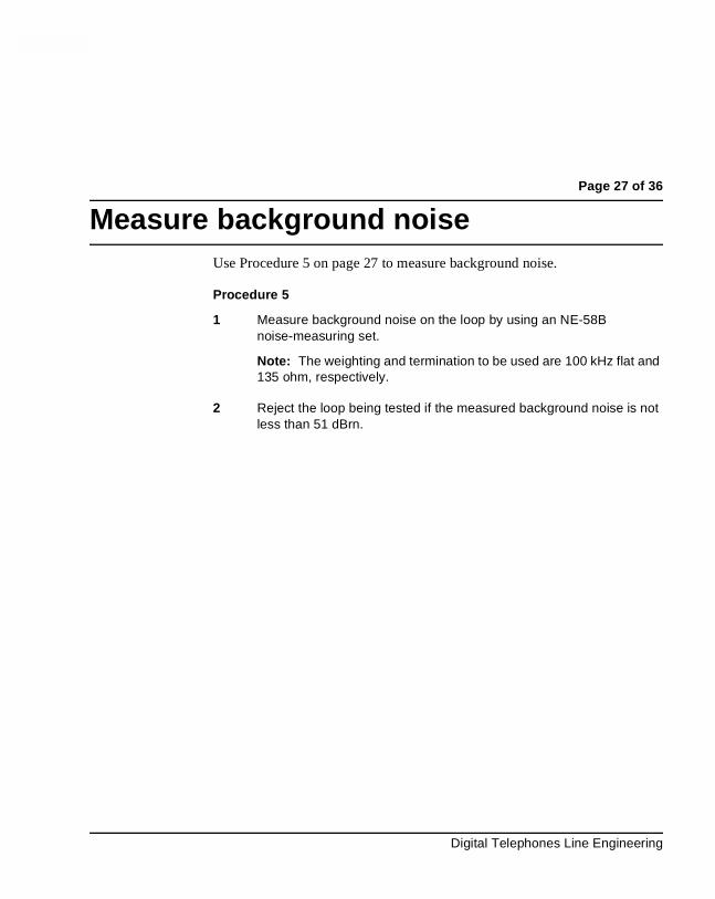
Measure background noiseUse Procedure 5 on page 27 to measure background noise.
Procedure 5
1 Measure background noise on the loop by using an NE-58B noise-measuring set.
Note: The weighting and termination to be used are 100 kHz flat and 135 ohm, respectively.
2 Reject the loop being tested if the measured background noise is not less than 51 dBrn.
Digital Telephones Line Engineering

Page 28 of 36 Measure background noise
553-2201-180 Standard 5.00 January 2002

Page 29 of 36
32
Calculate expected pulse lossUse Procedure 6 on page 29 to calculate expected pulse loss.
Procedure 6
1 Collect loop makeup data between the line card and the terminal. For each cable section, the data required is:
• cable type (PIC or pulp)
• gauge
• length
• type of plant construction (underground, aerial, or in-building)
2 Calculate individual cable section losses by using the figures in Table 2, “Cable attenuation at 256 kHz and 21.1 degrees C (70 degrees F),” on page 31 through Table 4, “Attenuation at 256 kHz for D inside wiring cable,” on page 31, and the following equation:
CSLi = SLi x Li
• CSLi = cable section loss for section i
• SLi = section length of section i
• Li = loss per unit length for section i
Digital Telephones Line Engineering

Page 30 of 36 Calculate expected pulse loss
3 Correct individual cable section losses for maximum cable temperature by using the following equation:
TCLi = CSLi x TCFi
• TCLi = temperature corrected loss for section i
• TCFi = temperature correction factor for section i
Correction factors:
• aerial cable TCF = 1.1
• underground cable TCF = 1.04
• in-building cable TCF = 1
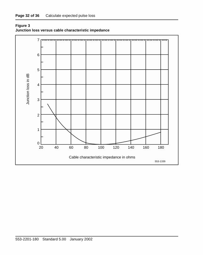
4 Determine junction loss (see Figure 3 on page 32).
Note: Junction loss due to gauge discontinuity of outside plant cables and D inside wire varies between 0.03 dB and 0.07 dB and can be ignored. However, AMP 25-pair under-carpet wiring has a characteristic impedance of 40 ohm at 256 kHz, and its junction loss is approximately 2 dB. This must be included in the calculation.
5 Calculate the expected pulse loss (EPL) by finding the sum of the items.
6 Reject loops whose expected pulse loss is greater than 12 dB.
Example of applying Procedure 6
Section 1:Mainframe bulkhead to DF1 - 500m, 26 AWG PIC, underground
Section 2:DF1 to DF2 - 200m, 26 AWG PIC, inside
Section 3:DF2 to terminal - 24 AWG NT D-inside
Therefore:SL1 = 1.5 km, SL2 = 0.2 km, SL3 = 0.1 km
From Table 2, “Cable attenuation at 256 kHz and 21.1 degrees C (70 degrees F),” on page 31 and Table 3, “Attenuation at 256 kHz for U/C cable,” on page 31:
L1 = 13.7 dB/km, L2 = 13.7 dB/km, L3 = 13.3 dB/km.
Using the equation in Step 2, we arrive at the following:CSL1 = 6.85 dB, CSL2 = 2.74 dB, and CSL3 = 1.33 dB
553-2201-180 Standard 5.00 January 2002

Calculate expected pulse loss Page 31 of 36
Temperature corrections:Using correction factors of TCF1 = 1.04, and TCF2 and TCF3 = 1, and using the equation in Step 3 results in TCL1 = 7.12 dB, TLC2 = 2.74 dB, and TCL3 = 1.33 dB.
Expected pulse loss (EPL) value:Neglecting any junction loss (see the note in Step 4), Step 5 results in an EPL value of TSL1 + TSL2 + TSL3 + 0 = 11.19 dB.
This is under the 12 dB limit and meets the criteria.
Table 2Cable attenuation at 256 kHz and 21.1 degrees C (70 degrees F)
Cable type
26 AWG 24 AWG 22 AWG 19 AWG
dB/kft dB/km dB/kft dB/km dB/kft dB/km dB/kft dB/km
PIC 4.2 13.7 3.1 10.2 2.5 8.1 1.7 5.6
Pulp 4.3 14.3 3.5 11.4 2.7 9.0 2.0 6.6
Table 3Attenuation at 256 kHz for U/C cable
WE 4-pair AMP 25-pair
dB/kft dB/km dB/kft dB/km
4.6 15.3 19.0 63.3
Table 4Attenuation at 256 kHz for D inside wiring cable
NT WE Superior General
dB/kft dB/km dB/kft dB/km dB/kft dB/km dB/kft dB/km
4.0 13.3 3.2 10.7 3.7 13.3 4.6 15.3
Digital Telephones Line Engineering
Page 32 of 36 Calculate expected pulse loss
Figure 3Junction loss versus cable characteristic impedance
Cable characteristic impedance in ohms
Junc
tion
loss
in d
B
553-1339
20 40 60 80 100 120 140 160 180
1
2
3
4
5
6
7
0
553-2201-180 Standard 5.00 January 2002

Page 33 of 36
34
Measure DC loop resistanceUse Procedure 7 on page 33 to measure DC loop resistance.
Procedure 7
Measure DC loop resistance by using standard procedures.
Note: The DC loop resistance limit of 175 ohm should be reduced by 1 ohm for each one percent of the total loop that is aerial cable.
Digital Telephones Line Engineering

Page 34 of 36 Measure DC loop resistance
553-2201-180 Standard 5.00 January 2002
Page 35 of 36
36
Index
Aattenuation, cable, 31Bbackground noise, 27
Ccable attenuation, 31cable lengths, maximum, 19cable pairs, engineering requirements, 9cabling, under-carpet
allowable loop length, 19attenuation, 31characteristic impedance, 9requirements, 9
calculatingDC loop resistance, 21expected pulse loss, 29
capacitance unbalance, testing, 24characteristic impedance
and junction loss, 32under-carpet cabling, 9
continuity, testing DC, 24
DDC loop resistance
calculating, 21maximum, 19measuring, 33
diagnostic tests, loop, 23
Eengineering telephone lines
flowchart, 10procedure, 9
expected pulse loss, calculating, 29
Iimpedance, cable characteristic
under-carpet cabling, 9vs. junction loss, 32
impulse noisemeasuring, 25vs. loop loss, 26
insulation resistance, testing, 23
Jjunction loss
determining, 30vs. cable characteristic impedance, 32
Lloop resistance. See DC loop resistanceloops
diagnostic tests, 23distances vs. AWG, 9requirements, 19selecting, 19
loss, loopmaximum allowable, 19vs. impulse noise counts, 26
Digital Telephones Line Engineering

Page 36 of 36 Index
Mmeasuring
background noise, 27DC loop resistance, 33impulse noise, 25
Nnoise measurements
background, 27impulse noise, 25
Rresistance. See DC loop resistance; insulation
resistance, testing
Sselecting loops, 19
553-2201-180 Standard 5.00 January 2002
Ttelephone lines, engineering, 9temperature, cable
and cable attenuation, 31correcting for, 30
testingcapacitance unbalance, 24DC continuity, 24foreign voltage, 23insulation resistance, 23See also measuring
tests, loop diagnostic, 23
Vvoltage, testing foreign, 23


Family Product Manual Contacts Copyright FCC notice Trademarks Document number Product release Document release Date Publish
Meridian 1
Digital Telephones Line Engineering
Copyright © 1989–2002 Nortel NetworksAll Rights ReservedInformation is subject to change without notice. Nortel Networks reserves the right to make changes in design or components as progress in engineering and manufacturing may warrant. This equipment has been tested and found to comply with the limits for a Class A digital device pursuant to Part 15 of the FCC rules, and the radio interference regulations of Industry Canada. These limits are designed to provide reasonable protection against harmful interference when the equipment is operated in a commercial environment. This equipment generates, uses and can radiate radio frequency energy, and if not installed and used in accordance with the instruction manual, may cause harmful interference to radio communications. Operation of this equipment in a residential area is likely to cause harmful interference in which case the user will be required to correct the interference at their own expense.SL-1 and Meridian 1 are trademarks of Nortel Networks.Publication number: 553-2201-180Document release: Standard 5.00Date: January 2002Printed in Canada
Top Related