


Languages
Pages
Legal


For any Queries: mail us at [email protected] or visit www.logictronix.com
Reference Tutorial on
Video Processing Subsystem (VPSS)
Feature Implementation on
Digilent PYNQ-Z1
Vitis and VIVADO Design Suite-2020.1
August 13, 2020

PYNQ Z1 Video Processing Subsystem Feature Implementation
Page 1 of 70
CHAPTER 1: INTRODUCTION
OVERVIEW
This project design document is based on the implementation of Video Processing Subsystem
on Digilent PYNQ-Z1 board along Vivado Design Suite 2020.1. This project uses Xilinx Video Test
Pattern Generator IP as the AXI4 video source for Video Processing Subsystem IP. The resulting
video stream goes all the way through series of video processing IPs to board output HDMI
interface and to HDMI monitor. The following picture depicts the general project overview.
Figure 1. Project Overview Block Diagram
This document mainly focuses on the Scalar, Color Space Conversion (CSC) and Frame Rate
Conversion (FRC) features of Video Processing Subsystem. This document approaches along
following sections, namely, Board overview, Video Processing Subsystem IP Overview, Design
Flow and Final Output. Under design flow section, the hardware design and the software design
will be explained. Under final output section, all the features output will be documented.
Zynq Host
Processor
Test
Pattern
Generator
Video
Processing
Subsystem
HDMI
Interface
DDR3
Memory
HDMI
Connector
HDMI
Video
Out
Digilent PYNQ-Z1 Board
Zynq-7020 APSoC FPGA
AXI4 to
Video out

PYNQ Z1 Video Processing Subsystem Feature Implementation
Page 2 of 70
BOARD OVERVIEW
Figure 2. Digilent Pynq-Z1 Board [Source: Digilent, Inc.]

PYNQ Z1 Video Processing Subsystem Feature Implementation
Page 3 of 70
PYNQ is an open-source project which allow to use Python language and libraries on the FPGA
device. Designers can exploit the benefits of programmable logic and microprocessors to build
more capable and exciting electronic systems [1]. PYNQ allow to combine the productivity of
the Python programming language with the flexibility of the Xilinx Zynq architecture [2].
That is, Python + Zynq=Pynq.
Figure 3. PYNQ
From a hardware perspective, this board is a very powerful board, featuring a ZYNQ 7020 APSoC,
high-speed peripherals, 512MB DDR3 Memory, HDMI sink port, HDMI source port as well as
Pmod and Arduino expansion possibilities.
PYNQ can be used with Zynq, Zynq UltraScale+, Zynq RFSoC, Alveo accelerator boards and AWS-
F1 to create high performance applications with:
• high frame-rate video processing
• hardware accelerated algorithms
• real-time signal processing
• low latency control

PYNQ Z1 Video Processing Subsystem Feature Implementation
Page 4 of 70
VIDEO PROCESSING SUBSYSTEM IP OVERVIEW
According to Xilinx, the Video Processing Subsystem is one of Xilinx LogiCORE IP, made from
Vivado HLS, is a collection of video processing IP subcores, bundled together in hardware and
software, abstracting the video processing pipe. It provides the end-user with an out of the box
ready to use video processing core, without having to learn about the underlying complexities.
The Video Processing Subsystem enables streamlined integration of various processing blocks
including scaling, deinterlacing, color space conversion and correction, Chroma resampling, and
frame rate conversion [3].
Figure 40. Full-Fledged Video Processing Subsystem
Key Features
• One, two, four, and eight pixel-wide AXI4-Stream video interface
• Video resolution support up to 8k at 30 fps
• Run-time color space support for RGB, YUV 4:4:4, YUV 4:2:2, YUV 4:2:0
• 8, 10, 12, and 16 bits per component support
• Deinterlacing: supports 32-bit and 64-bit memory address
• Scaling
• Color space conversion and correction
• Chroma resampling between YUV 4:4:4, YUV 4:2:2, YUV 4:2:0
• Frame rate conversion using dropped/ repeated frames.
PYNQ Z1 Video Processing Subsystem Feature Implementation
Page 5 of 70
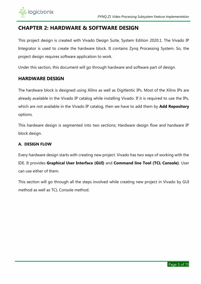
CHAPTER 2: HARDWARE & SOFTWARE DESIGN
This project design is created with Vivado Design Suite, System Edition 2020.1. The Vivado IP
Integrator is used to create the hardware block. It contains Zynq Processing System. So, the
project design requires software application to work.
Under this section, this document will go through hardware and software part of design.
HARDWARE DESIGN
The hardware block is designed using Xilinx as well as Digitlentic IPs. Most of the Xilinx IPs are
already available in the Vivado IP catalog while installing Vivado. If it is required to use the IPs,
which are not available in the Vivado IP catalog, then we have to add them by Add Repository
options.
This hardware design is segmented into two sections; Hardware design flow and hardware IP
block design.
A. DESIGN FLOW
Every hardware design starts with creating new project. Vivado has two ways of working with the
IDE. It provides Graphical User Interface (GUI) and Command line Tool (TCL Console). User
can use either of them.
This section will go through all the steps involved while creating new project in Vivado by GUI
method as well as TCL Console method.
PYNQ Z1 Video Processing Subsystem Feature Implementation
Page 6 of 70
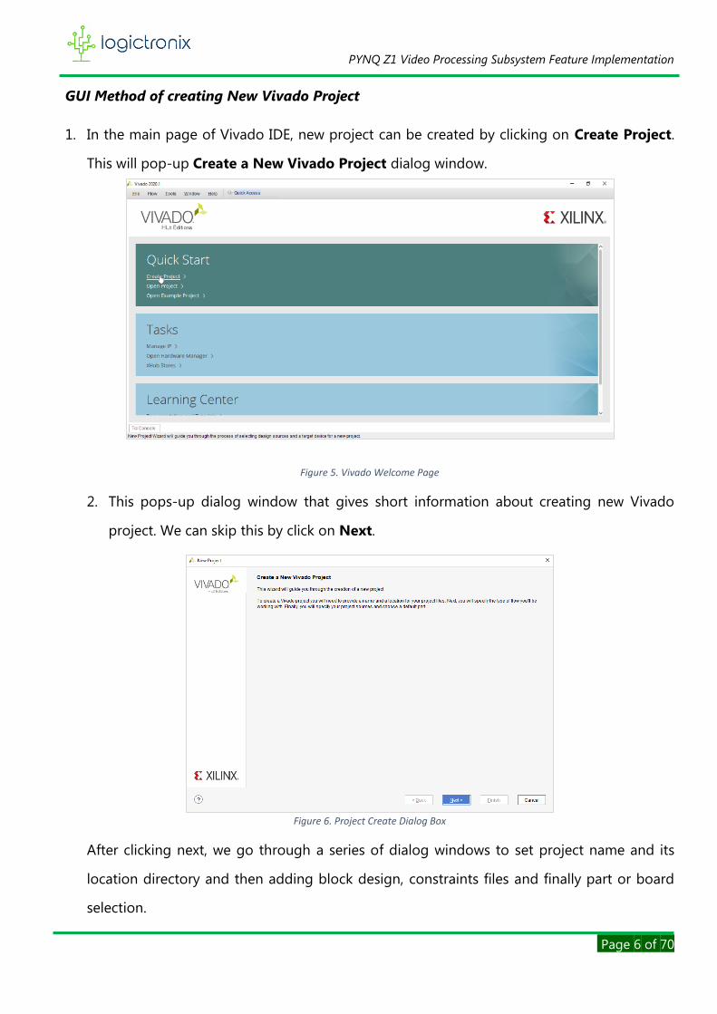
GUI Method of creating New Vivado Project
1. In the main page of Vivado IDE, new project can be created by clicking on Create Project.
This will pop-up Create a New Vivado Project dialog window.
Figure 5. Vivado Welcome Page
2. This pops-up dialog window that gives short information about creating new Vivado
project. We can skip this by click on Next.
Figure 6. Project Create Dialog Box
After clicking next, we go through a series of dialog windows to set project name and its
location directory and then adding block design, constraints files and finally part or board
selection.

PYNQ Z1 Video Processing Subsystem Feature Implementation
Page 7 of 70
3. Under this Project Name dialog window, we have to give Project Name and Project
Location for our new project. We can Browse the directory to locate our project. After that,
we proceed ahead by clicking on Next.
Note: There should not be any spaces or special characters (except ‘_’ & ‘-‘) in the project
name and the directory. We must also check the project name length and directory path
length. Because, windows OS only support 255 characters.
Figure 7. Project Name & location setting dialog window
4. Under this window, we have to specify Project Type to be created. There are five options to
specify the type of our project.
Figure 8. Project Type selection window

PYNQ Z1 Video Processing Subsystem Feature Implementation
Page 8 of 70
Based on the requirements of the project design, we can select any of these types. In our
project design scenario, we go selecting RTL Project type. Because, this type of project allows
us to add sources, block design in the IP integrator, simulate the design, run RTL analysis,
synthesis, implementation, design planning and analysis, generate bit stream. After this, click
Next to go another project dialog window.
5. Under this window, we Add Sources, such as, HDL, netlist, Block Design, IP files. If we want
to add such sources, we can click Add Files button or Plus icon. We can also create such files
ourselves by clicking on Create File button. We can click on Add Directories to add source
location.
Besides this, we can specify Target language and Simulator language. By default, these
languages are selected to Verilog and Mixed respectively. After that we proceed to Next.
NOTE: we can also skip this add source window. Because, Vivado also allows us to add such
sources and files after creating the project.
Figure 9. Add source dialog window
PYNQ Z1 Video Processing Subsystem Feature Implementation
Page 9 of 70
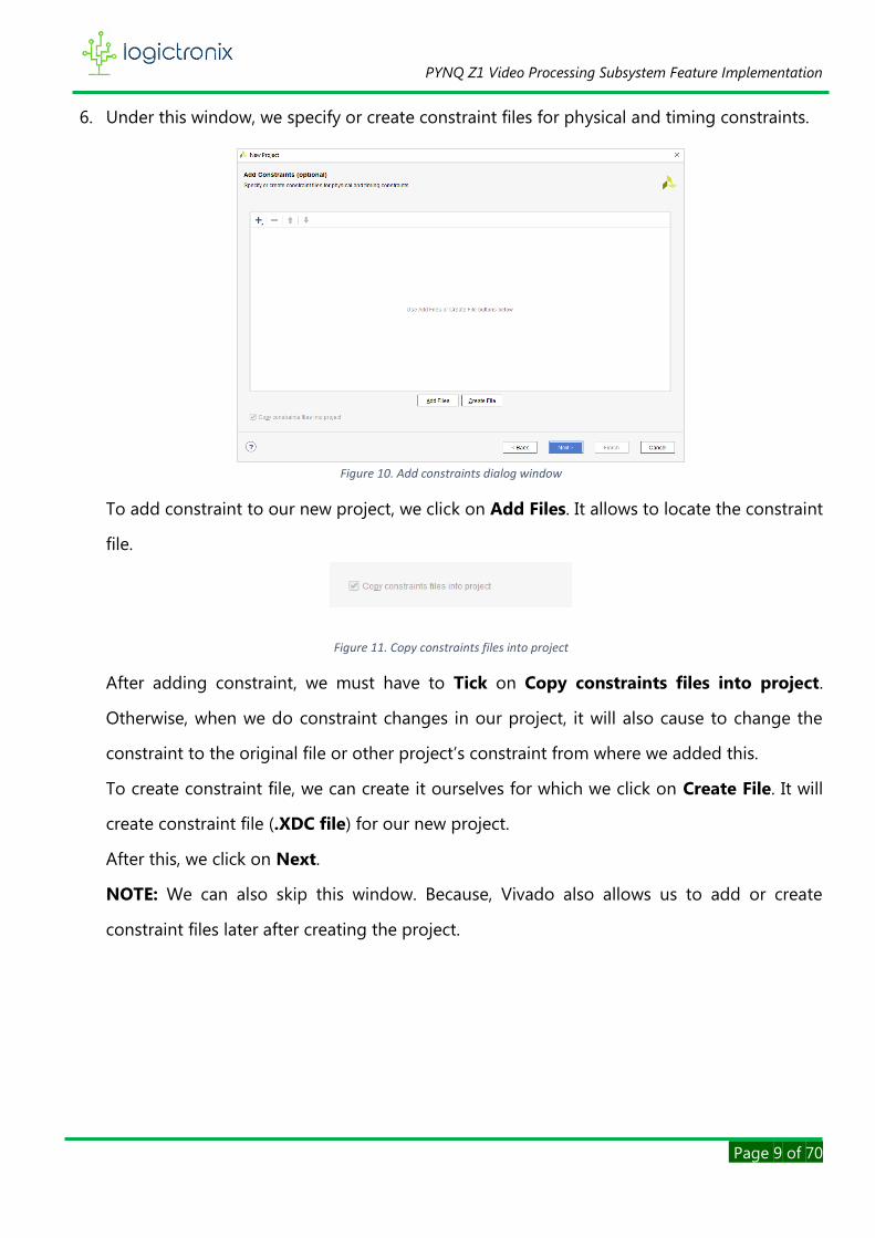
6. Under this window, we specify or create constraint files for physical and timing constraints.
Figure 10. Add constraints dialog window
To add constraint to our new project, we click on Add Files. It allows to locate the constraint
file.
Figure 11. Copy constraints files into project
After adding constraint, we must have to Tick on Copy constraints files into project.
Otherwise, when we do constraint changes in our project, it will also cause to change the
constraint to the original file or other project’s constraint from where we added this.
To create constraint file, we can create it ourselves for which we click on Create File. It will
create constraint file (.XDC file) for our new project.
After this, we click on Next.
NOTE: We can also skip this window. Because, Vivado also allows us to add or create
constraint files later after creating the project.

PYNQ Z1 Video Processing Subsystem Feature Implementation
Page 10 of 70
7. Under this window, we have to choose Board or Part to implement our project.
Figure 12. Project part or project board selection window
In this window, there are two tabs, i.e. Parts and Boards. We can go to parts tab to select
board part or we can go to boards tab to select board. Under both tabs, we see Xilinx’s part
and board lists respectively. These are only visible as long as these are installed. We can also
Search board or part to select. To install or update any board definition, we can go to
Install/Update Boards on top right of this window.
In our project design, we select PYNQ-Z1 board, after which we proceed Next.
8. Under this window, we see New Project Summary.
Figure 13. Project summary dialog window

PYNQ Z1 Video Processing Subsystem Feature Implementation
Page 11 of 70
It gives the information about project name, selection of source file, constraint file and finally
information of selected part or board.
9. Now, we click on Finish to create new Vivado project based on the above steps parameters.
10. When new project create is successful, it opens into Vivado IDE as shown below.
Figure 14. Vivado IDE after creating new window
TCL Console Command Method of creating New Vivado Project
We can also create new project by using TCL command, which is faster than GUI method. In this
method, we use following command to create the project.
1. To create the project with part selection, we use create_project and –part command as
following;
create_project <project_name> <project_directory/project_name> -part <part>
Here, we give project name in <project_name> field,
We give project directory with project name in <project_directory/project_name> field
And finally we have to specify part designation in <part> field.

PYNQ Z1 Video Processing Subsystem Feature Implementation
Page 12 of 70
In this project design scenario, we are intending to use PYNQ-Z1 board. So, in order to create
project, the TCL command becomes
create_project pynq_z1_vprocss D:/LogicTronix/ pynq_z1_vprocss -part xc7z020clg400-1
Now, we have to enter this command in TCL console as following.
Figure 15. Vivado welcome page with TCL Console
2. After entering the command, Vivado quickly creates new project and opens Vivado IDE

PYNQ Z1 Video Processing Subsystem Feature Implementation
Page 13 of 70
3. The Vivado creates the project with Project Part. If we want to add the board definition to
current project, then we have to simply enter the following TCL command.
set_property board_part <board_definition> [current_project]
Here, we have to specify the board definition of project part.
In this project design, PYNQ-Z1 board is used. So, we specify this board definition as
following;
set_property board_part www.digilentinc.com:pynq-z1:part0:1.0 [current_project]
4. After entering the TCL command, now the project part is changed to board.
Figure 16. Vivado IDE window after changing project part
In this way, by using TCL command, Vivado creates new project quickly within a few steps.
Now after creating the project, we need to add diagram canvas to create IP blocks. For this, we
have to follow the steps;
Flow Navigator > IP Integrator > Create Block Design
This pops-up a window, where we set the block design name. And click on OK.

PYNQ Z1 Video Processing Subsystem Feature Implementation
Page 14 of 70
Figure 17. Block Design name pop-up window
We can also enter following TCL command to create the block design instead of GUI method.
create_bd_design "design_1"
Now this opens diagram canvas
Figure 18. Vivado IDE after creating block design
Before starting to create hardware block design, we have to check IP Repositories. This is only
required when we need to add IPs that are not available in Vivado IP catalog. That means,
Vivado has already some of Licensed Xilinx IPs. And if our block design has IPs which are not
found in the Vivado IP catalog, then we need to add those missing.
In this project design, we have to interface with HDMI. So that, we have to add Digilent
RGB2DVI IP to Vivado IP repository.

PYNQ Z1 Video Processing Subsystem Feature Implementation
Page 15 of 70
Repositories can be added by following steps;
Flow Navigator Project Manager Setting
This opens Setting dialog.
Project Setting IP Repository
Click on to go to locate IP repository directory. Then click on OK to finish adding IP
repositories.
Figure 19. Add IP Repositories dialog window
Besides this, we can also enter TCL command to add IP repositories. For this, we use following
command.
set_property ip_repo_paths <ip_repo_directory> [current_project]
Here, we have to locate the IP repositories directory in <ip_repo_directory> field.
Now, we are all set. We can proceed to hardware IP block design.

PYNQ Z1 Video Processing Subsystem Feature Implementation
Page 16 of 70
B. IP BLOCK DESIGN
In this section, we create IP blocks by adding the required IPs from the IP catalog.
Figure 20. Adding IP to IP Integrator
To begin adding IPs, we can click on any icon within diagram canvas or we can also use shortcut
key Ctrl+I. This will pop-up the IP selection window. Here, we can scroll down or use search box
to find necessary IPs.
In this project design, we have following major IPs. They are;
• Zynq Processing System,
• Video Processing Subsystem (VPSS),
• Test Pattern Generator (TPG),
• Video Timing Controller (VTC),
• Clocking Wizard,
• AXI4-Stream Subset Converter,
• AXI4-Stream-to-Video Out and
• RGB2DVI.

PYNQ Z1 Video Processing Subsystem Feature Implementation
Page 17 of 70
We add and connect these IPs one after another. We also do run block automation and run
connection automation so that Vivado IP integrator automatically does necessary IP connections,
preset configurations and addition of interconnect IPs and so on.
All the IPs and their customizations and connections are described as following;
1. Zynq Processing System
The processing system (PS) in Zynq-7000 is dual-core ARM cortex A9 processor or CPU placed
in the same FPGA chip along with the programmable logic (PL). This is the central processing
system of the project. It provides the configuration and control of all IP drivers and hence the
video processing. The DDR of processing system (PS DDR) is used as frame buffer. This frame
buffer is used by video processing subsystem IP to achieve various features.
Figure 21. Zynq Processing System
In case of current project design, High Performance (HP0) Slave Interface is enabled, which
provides DDR memory access to video processing subsystem IP. General Purpose (GP0) Master
interface is enabled, which is used to configure and control the video processing IP chain by data
read and data write process.
FCLK_CLK0 is enabled in the PS. This clock is set to generate 148.5 MHz. The clock pin of all the
video processing IPs are connected to this clock source.

PYNQ Z1 Video Processing Subsystem Feature Implementation
Page 18 of 70
2. Test Pattern Generator (TPG) v8.0
Figure 22. Video Test Pattern Generator
TPG is used as the video source for this design. This IP generates the different video test pattern
data. The control bus is used to program the IP from SDK. The specific pattern selection is also
done through programming. However, to generate specific type of pattern, user has to enable
all the pattern type in the hardware design.
Figure 23. TPG pattern enable
The video stream is then fed to video processing subsystem IP.
More information about this IP can be found on its product guide PG103. [4]

PYNQ Z1 Video Processing Subsystem Feature Implementation
Page 19 of 70
3. Video Processing Subsystem (VPSS) v2.1
Figure 24. Full-Fledged Video Processing Subsystem
VPSS enables streamlined integration of various processing blocks including scaling,
deinterlacing, color space conversion and correction, Chroma resampling, and frame rate
conversion.
Figure 25. VPSS Customization
Under customization, VPSS IP can be operated in one of the following modes, such as, full-
fledged mode, scalar mode, deinterlacing mode, color space conversion mode and Chroma Re-
sampler mode. But this project design uses full-fledged mode. By this mode, all other mode

PYNQ Z1 Video Processing Subsystem Feature Implementation
Page 20 of 70
functionalities can be obtained. And in this mode, AXI-memory mapped interfaced is added to
IP so that IP can be connected to DDR memory for frame processing.
This IP also has control bus for its configuration from SDK. We can do coding to generate
different functional outputs.
This IP receives video stream from TPG and then generates output. This output is fed to
following video processing IPs.
Figure 26. VPSS Input Output Connection
Video Processing Subsystem IP has aresent_io_axis[0:0] output reset pin. This is only visible
when this IP is customized to full-fledged mode. This reset pin is used to control the reset line of
upstream and downstream IPs. That means, until VPSS IP gets ready to work, its reset pin is used
to set the upstream and downstream IPs in reset mode. So that, these IPs will not send or receive
the stream. In this project design, the reset pin of VPSS IP is connected to input reset pin of TPG
and AXI4S Subset Converter IPs.
Figure 27. VPSS reset line control
Video Processing Subsystem has multitude of features. For more technical details, user can visit
Video Processing Subsystem Product Guide [5].
4. AXI4-Stream Subset Converter

PYNQ Z1 Video Processing Subsystem Feature Implementation
Page 21 of 70
This IP is mainly used for proper AXI4-Stream width conversion. If stream width has to be
converted such as 24 bit to 16 bit or vice versa, this IP can be used. Otherwise, this IP can be
omitted. For more details, we visti its product guide PG085. [6]
In our project design, this IP is used for 24 bit conversion for RGB Stream.
5. Clocking Wizard v6.0
Clocking Wizard is a clock generator IP. It helps creating the clocking circuit for the required
output clock frequency, phase, and duty cycle using a mixed-mode clock manager (MMCM)
(E2/E3/E4) or phase-locked loop (PLL) (E2/E3/E4) primitive. This IP accepts up to two input clocks
and generates up to seven output clocks per clock network.
Figure 28. Clocking Wizard IP
In this project design, clocking wizard IP receives one input clock and generates one output clock.
The generated output clock forms the pixel clock for VTC IP, AXI4-Stream-to-Video Out IP and
RGB2DVI IP. This IP can be customized either in static mode or dynamic mode. In static mode,
the IP generates the fixed output clock as defined by user. On the other hand, if IP is in dynamic
mode, any required output clock can be generated as per programming. For this, AXI-Lite
interface is added to IP. Under the customization window, we can enable dynamic
reconfiguration mode.

PYNQ Z1 Video Processing Subsystem Feature Implementation
Page 22 of 70
Figure 29. Clocking Wizard Customization
In this project design, clocking wizard is enabled with dynamic reconfiguration. This is because
of the fact that when we need to vary the output resolution, we must require corresponding
resolution pixel clock. Therefore, whenever video processing subsystem performs scaling to
different resolution, the clocking wizard is programmed to generate the pixel clock, which is
corresponding to scaled resolution.
Figure 30. Clocking Wizard Output Clock
Clocking
wizard
Video
Timing
Controller
AXI4S
-to-
Video
Out
RGB
-to-
DVI
ACLK
Pixel Clock

PYNQ Z1 Video Processing Subsystem Feature Implementation
Page 23 of 70
Figure 31. Clocking wizard output clock connection
Detailed information can be gained from Clocking Wizard Product Guide[7].
6. Video Timing Controller (VTC)
The Video Timing Controller IP core is a general purpose video timing generator and detector.
The core is highly programmable through a comprehensive register set allowing control of
various timing generation parameters. This programmability is coupled with a comprehensive set
of interrupt bits which provides easy integration into a processor system for in-system control of
the block in real-time. The Video Timing Controller is provided with an optional AXI4-Lite
interface.
Figure 32. Video Timing Controller (VTC) IP

PYNQ Z1 Video Processing Subsystem Feature Implementation
Page 24 of 70
Unlike the programmability, VTC can be configured as static for static video modes. In other
words, if video processing block is designed for only a particular video resolution, VTC IP can be
customized to support that video resolution only.
Figure 33. VTC IP Customization
In this project design, the VTC is used to generate the video timing. AXI4-Lite Interface is also
enabled. By doing this, VTC IP can be programmed to generate different video timing signals in
real-time. Based on the output video resolution set in the video processing subsystem, the VTC
IP generates corresponding timing signals.
For more details, we can visit product guide PG016 [8].
7. AXI4-Stream-to-Video Out
The AXI4-Stream to Video Out IP core is designed to interface from the AXI4-Stream interface
implementing a Video Protocol to a video source, such as, parallel video data, video syncs, and
blanks. This core works with the Video Timing Controller IP. This core provides a bridge between
video processing cores with AXI4-Stream interfaces and a video output.
PYNQ Z1 Video Processing Subsystem Feature Implementation
Page 25 of 70
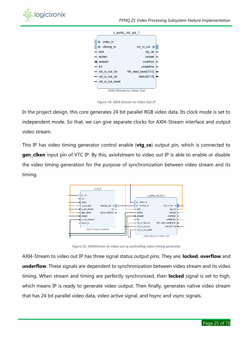
Figure 34. AXI4-Stream to Video Out IP
In the project design, this core generates 24 bit parallel RGB video data. Its clock mode is set to
independent mode. So that, we can give separate clocks for AXI4-Stream interface and output
video stream.
This IP has video timing generator control enable (vtg_ce) output pin, which is connected to
gen_clken input pin of VTC IP. By this, axis4stream to video out IP is able to enable or disable
the video timing generation for the purpose of synchronization between video stream and its
timing.
Figure 35. AXI4Stream-to-video out ip controlling video timing generator
AXI4-Stream to video out IP has three signal status output pins. They are; locked, overflow and
underflow. These signals are dependent to synchronization between video stream and its video
timing. When stream and timing are perfectly synchronized, then locked signal is set to high,
which means IP is ready to generate video output. Then finally, generates native video stream
that has 24 bit parallel video data, video active signal, and hsync and vsync signals.

PYNQ Z1 Video Processing Subsystem Feature Implementation
Page 26 of 70
8. RGB-to-DVI
Figure 36. RGB-to-DVI Encoder IP
In order to display video stream on output monitor, we have to use this IP. This is because, PYNQ-
Z1 only has HDMI to display the video. So that, we need to access pynq HDMI interface. RGB-to-
DVI IP is made by Digilent that facilitates to access HDMI interface. This IP interfaces directly to
raw transition-minimized differential signaling (TMDS) clock and data channel outputs as defined
in DVI 1.0 specs for Source devices. It encodes 24 bit parallel video data from AXI4-Stream-to-
Video-out IP along with pixel clock and synchronization signals. It supports resolution from
1920x1080p@60Hz to 800x600p@60Hz with pixel frequency 148.5MHz-40MHz respectively. For
more information, we can visit www.digilentic.com.
Figure 37. TMDS connected to hdmi_tx port
In this project design, this IP output pin, i.e. TMDS is connect to hdmi_tx port.
PYNQ Z1 Video Processing Subsystem Feature Implementation
Page 27 of 70
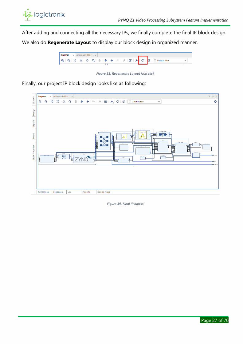
After adding and connecting all the necessary IPs, we finally complete the final IP block design.
We also do Regenerate Layout to display our block design in organized manner.
Figure 38. Regenerate Layout icon click
Finally, our project IP block design looks like as following;
Figure 39. Final IP blocks

PYNQ Z1 Video Processing Subsystem Feature Implementation
Page 28 of 70
Figure 40. Final Block Design
PYNQ Z1 Video Processing Subsystem Feature Implementation
Page 29 of 70
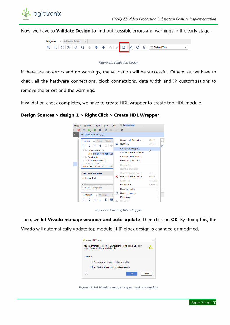
Now, we have to Validate Design to find out possible errors and warnings in the early stage.
Figure 41. Validation Design
If there are no errors and no warnings, the validation will be successful. Otherwise, we have to
check all the hardware connections, clock connections, data width and IP customizations to
remove the errors and the warnings.
If validation check completes, we have to create HDL wrapper to create top HDL module.
Design Sources > design_1 > Right Click > Create HDL Wrapper
Figure 42. Creating HDL Wrapper
Then, we let Vivado manage wrapper and auto-update. Then click on OK. By doing this, the
Vivado will automatically update top module, if IP block design is changed or modified.
Figure 43. Let Vivado manage wrapper and auto-update

PYNQ Z1 Video Processing Subsystem Feature Implementation
Page 30 of 70
Now, we have to add the constraint file that will be used for physical ports mapping with IP
block ports. For this, we follow,
Constraints > Right Click > Add Sources
Figure 44. Add constraint file
This will pop-up Add Source dialog window, where we have to select Add or create constraints.
And then Next.
Figure 45. Add constraint dialog window
This now opens Add or Create Constraints dialog window. Here we can either locate the
constraint file (XDC file) or create our own constraints. After doing this, we click on Finish to
complete the addition of constraint in our project design.

PYNQ Z1 Video Processing Subsystem Feature Implementation
Page 31 of 70
Figure 46. Add or Create constraint dialog window
After this, we have to check constraints. There should be no error mapping between physical port
and block design port. Otherwise, bitstream generation will be failed.
After making everything well, we can now generate bitstream. We can directly follow
Flow Navigator > Program and Debug > Generate Bitstream
Figure 47. Starting Generation of bitstream
PYNQ Z1 Video Processing Subsystem Feature Implementation
Page 32 of 70
After that, we should hit Yes if it pops-up the messages saying synthesis or implementation result
not available. In other words, if there is no synthesis or implementation result, the Vivado will
automatically generates them one-after-another before generating bitstream.
We can use TCL command to instantiate the bitstream generation.
launch_runs impl_1 -to_step write_bitstream -jobs 2
If everything goes well, bitstream generation is started. And we have to wait until it is completed.
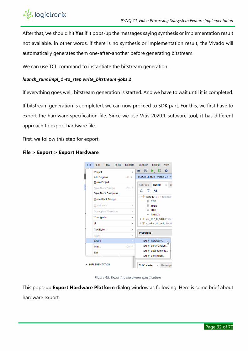
If bitstream generation is completed, we can now proceed to SDK part. For this, we first have to
export the hardware specification file. Since we use Vitis 2020.1 software tool, it has different
approach to export hardware file.
First, we follow this step for export.
File > Export > Export Hardware
Figure 48. Exporting hardware specification
This pops-up Export Hardware Platform dialog window as following. Here is some brief about
hardware export.

PYNQ Z1 Video Processing Subsystem Feature Implementation
Page 33 of 70
Figure 49. Platform type selection window
Under Platform type, we have to select the Fixed type because, we are developing Embedded
Software. Then we click on Next.
Now, Output dialog window opens, where have to select Include bitstream output option.
Because, our software application requires hardware specification.
Figure 50. Output type selection window
Then click on Next. This opens another window as shown in image below.

PYNQ Z1 Video Processing Subsystem Feature Implementation
Page 34 of 70
Figure 51. XSA File selection window
The hardware specification is exported as XSA file. So that, under this window, we have to enter
the valid xsa file name and the valid directory. In this directory, our xsa file will be exported. To
locate the directory, we can Browse the location. And after this, we click on Next.
After this, information dialog window is opened, where we click on Finish to complete the
hardware export.
If everything goes well, the hardware export is successful. So, we can now proceed to software
design section.

PYNQ Z1 Video Processing Subsystem Feature Implementation
Page 35 of 70
SOFTWARE DESIGN
For the software design, we use Vitis Unified Software Development Platform 2020.1. As for
introduction, the Vitis unified software platform is a new tool that combines all aspects
of Xilinx software development into one unified environment.
It enables the development of embedded software as well as accelerated applications on
heterogeneous Xilinx platforms including FPGAs, SoCs, and ACAPs. For more details, we can visit
www.xilinx.com.
This section divulges software design flow and software application coding as following.
A. DESIGN FLOW
In this sub-section, we go through all the steps involved while creating software platform and
application projects.
1. After the exporting the hardware specification, we launch the Vitis IDE from Vivado IDE by
following steps;
Tools > Launch Vitis IDE
Figure 52. Launching Vitis 2020.1
This launches the Vitis IDE onward.
2. During this launching, the Vitis pops-up a dialog window as shown below to select directory
for workspace. Because, Vitis uses this directory to store the development artifacts.

PYNQ Z1 Video Processing Subsystem Feature Implementation
Page 36 of 70
Figure 53. Workspace directory selection
We have to set the directory in the workspace directory field. We can also click dropdown to
see previously used directories. We can select one of these for workspace. However, we can
also Browse to locate our desired workspace directory.
Then we click on Launch to start the Vitis IDE completely.
3. Now, the Vitis IDE opens its welcome page at the beginning.
Figure 54. Vitis welcome page
4. Welcome page has various selection options, out of which we first go through Create
Platform Project. This opens Create new platform project dialog window.

PYNQ Z1 Video Processing Subsystem Feature Implementation
Page 37 of 70
Figure 55. Create new platform project window
Here, we specify Project name and it location. By default Vitis uses default location to store
platform project. While giving the project name, there should be no space and special
characters [except “_” and ”-“] in the name. We must also check the project name length
and directory path length. Because, windows OS only supports 255 characters.
Then, click on Next.
5. Now, another dialog window is opened to create platform project from hardware
specification or to create platform project from existing platform.
PYNQ Z1 Video Processing Subsystem Feature Implementation
Page 38 of 70
We select first option. Because, we create new platform project from our exported hardware
specification.
Then go to Next.
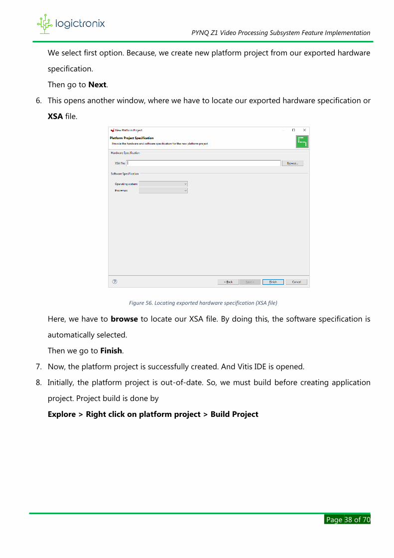
6. This opens another window, where we have to locate our exported hardware specification or
XSA file.
Figure 56. Locating exported hardware specification (XSA file)
Here, we have to browse to locate our XSA file. By doing this, the software specification is
automatically selected.
Then we go to Finish.
7. Now, the platform project is successfully created. And Vitis IDE is opened.
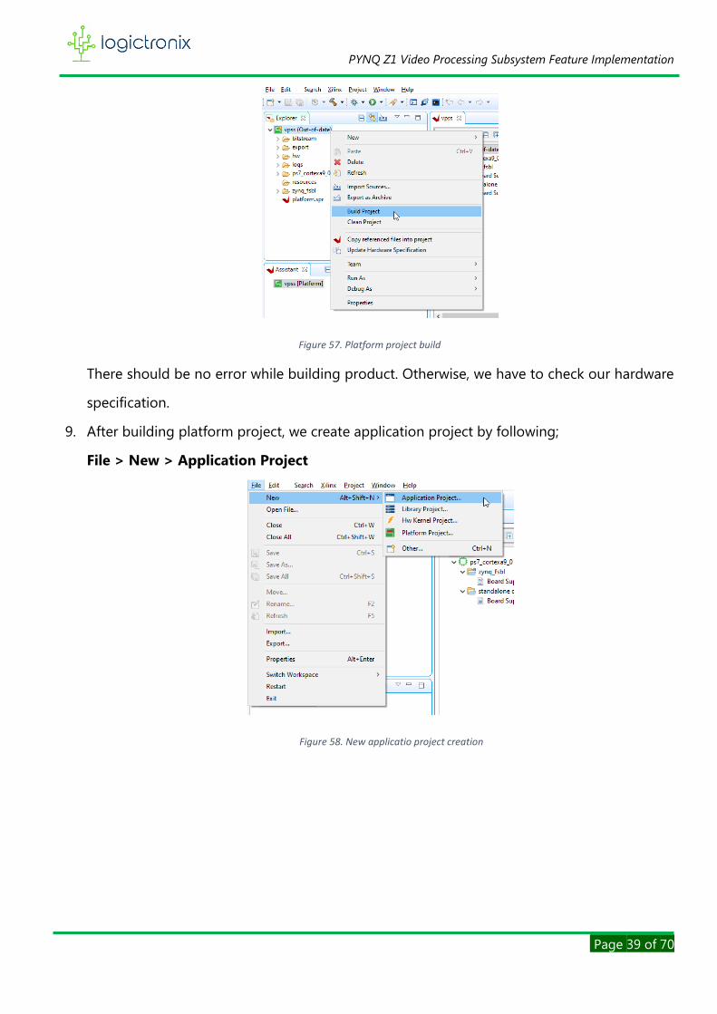
8. Initially, the platform project is out-of-date. So, we must build before creating application
project. Project build is done by
Explore > Right click on platform project > Build Project
PYNQ Z1 Video Processing Subsystem Feature Implementation
Page 39 of 70
Figure 57. Platform project build
There should be no error while building product. Otherwise, we have to check our hardware
specification.
9. After building platform project, we create application project by following;
File > New > Application Project
Figure 58. New applicatio project creation

PYNQ Z1 Video Processing Subsystem Feature Implementation
Page 40 of 70
10. Now, a dialog window is opened.
Figure 59. Platform selection window
Here, we select platform project that was initially created. Under this window, we can also
create platform project here, if we initially create application project.
Then we click on Next.
11. After this, another window is popped-up, where we set our application project name.
Figure 60. Setting project name
Here, we give the application project in such a way that it should contain any space or special
characters except ‘_’ & ‘-‘.
Then we proceed Next.

PYNQ Z1 Video Processing Subsystem Feature Implementation
Page 41 of 70
12. Now, Domain dialog window is opened. We do not do anything here. Because, domain is
already specified by default. Therefore, we can directly proceed Next.
13. This time, Template dialog window is opened.
Figure 61. Application template selection
Here, we select one of the available templates. Since we are developing standalone
embedded application, we choose either Empty Application or Hello World software
template.
Here is the note that we can select any available software application templates between
these templates. Only the difference, in empty application, user has to add everything, such
as, platform codes for the project whereas hello world project has everything for starting new
project. It is likely a ready to use project. User can write or import the programs directly. And
if project build is successful, user can quickly launch the application.
Then we click on Finish to complete the application project creation.

PYNQ Z1 Video Processing Subsystem Feature Implementation
Page 42 of 70
Figure 62. Vitis IDE.
This is what Vitis IDE looks like after we create platform project and application project.
Now, we can proceed to write our software application code. This is included in software
application design section.
B. SOFTWARE APPLICATION DESIGN
After successful application project creation, we can write either our own code or import other
codes. In this project design, we write code ourselves. To code ourselves, we have to create c-
programming file (.c file). We create this file by following steps;
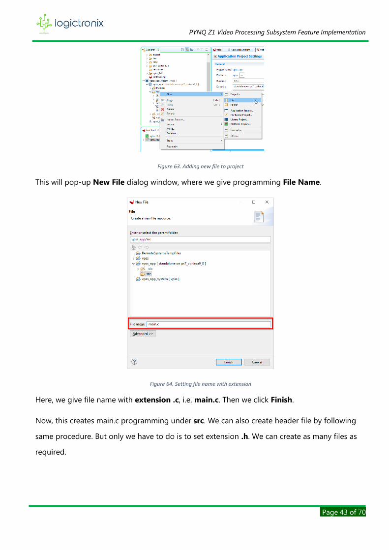
Explorer > Application Project > src > Right Click > New > File
PYNQ Z1 Video Processing Subsystem Feature Implementation
Page 43 of 70
Figure 63. Adding new file to project
This will pop-up New File dialog window, where we give programming File Name.
Figure 64. Setting file name with extension
Here, we give file name with extension .c, i.e. main.c. Then we click Finish.
Now, this creates main.c programming under src. We can also create header file by following
same procedure. But only we have to do is to set extension .h. We can create as many files as
required.

PYNQ Z1 Video Processing Subsystem Feature Implementation
Page 44 of 70
Figure 65. Software Application Architecture
The above diagram represents three level software application architecture. At the top level, i.e.
layer 3, the main function resides, from where software application starts. The main function
becomes entry point. It has instances for peripheral and main menu display, which then calls
layer 2 functions. In layer 2, all the peripherals initialization instances are loaded, which then calls
layer 1 to initialize each and every peripherals and finally configures these peripherals, which
Main function
Peripherals Main menu
TPG
co
nfi
gura
tio
n
VP
SS
Co
nfi
gura
tio
n
Clo
ckin
g w
izar
d
con
figu
rati
on
TPG
Men
u
Scal
ing
Men
u
CSC
Men
u
FRC
Men
u
Re
ad U
ser
Inp
ut
VTC
co
nfi
gura
tio
n
XV
_tp
g
xvtc
xvp
rocs
s
xclk
_wiz
xuartps
Layer
1
Layer
2
Layer
3
Software Application
Xilinx Hardware
Xil
inx D
river

PYNQ Z1 Video Processing Subsystem Feature Implementation
Page 45 of 70
then configures Xilinx hardware through drivers. So that, application starts working. In meantime,
layer 2 main menu function displays main menu on the terminal and background process runs
to read the user input and to display corresponding sub menus. When user gives input, such as,
TPG pattern selection, resolution selection, and color format selection and so on, the
corresponding peripheral is configured and finally hardware is updated to give output. And
corresponding menu is also displayed on the terminal and again background process runs to
take other user input.
The details of all the functions of this software design are mentioned below.
The above code snippet is taken from main function. Upon execution, this function calls following
functions;
1. init_periphs(&app_periphs)
2. init_application(&app_periphs)
3. MainMenu(&app_periphs) and mainMenuState(&app_periphs)
Where, app_periphs is the structure variable that is declared as following;
app_periphs_t is the structure that is declared in header file. The following code snippet shows
structure declaration.
The structure is so declared because, it keeps all the different peripherals in a single entity, which
then helps to manage video processing pipe and its stream parameters.
PYNQ Z1 Video Processing Subsystem Feature Implementation
Page 46 of 70
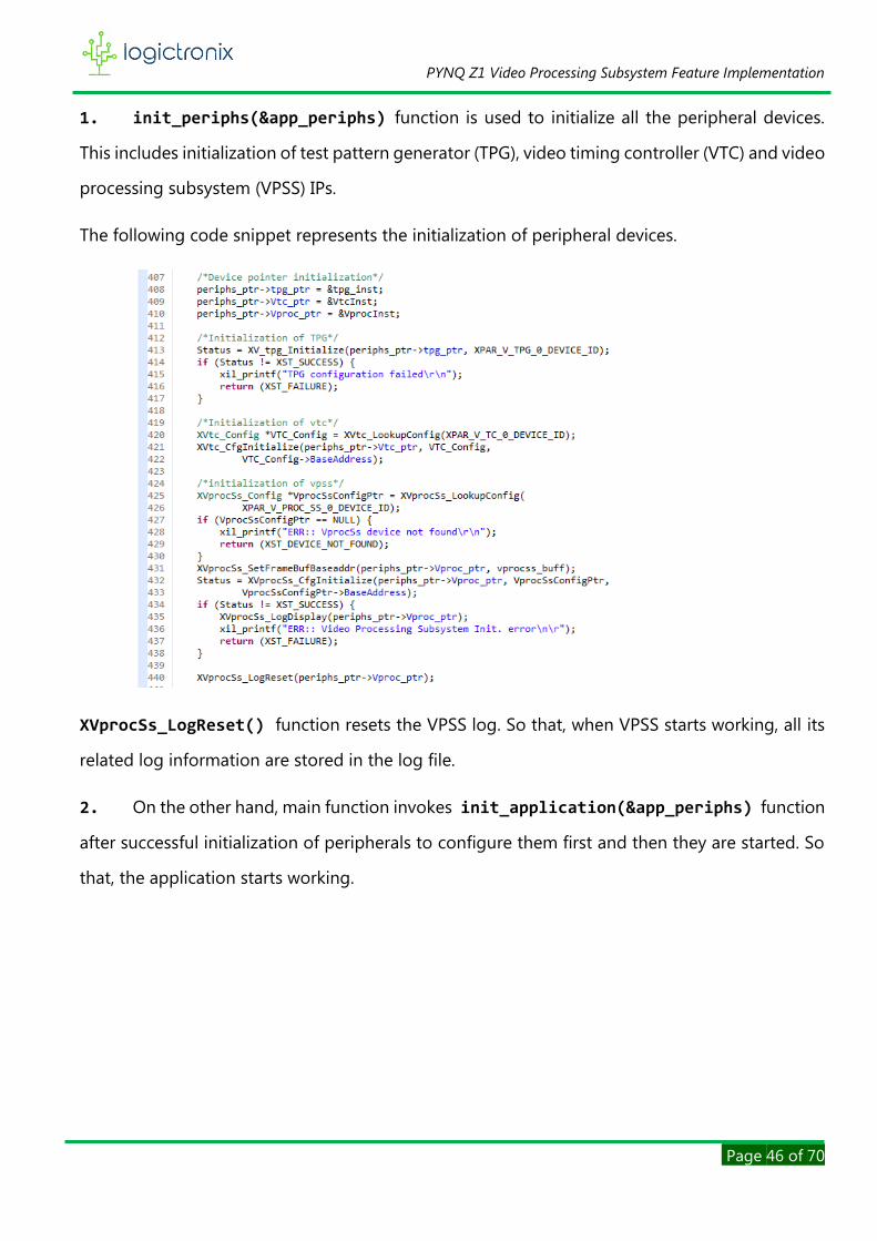
1. init_periphs(&app_periphs) function is used to initialize all the peripheral devices.
This includes initialization of test pattern generator (TPG), video timing controller (VTC) and video
processing subsystem (VPSS) IPs.
The following code snippet represents the initialization of peripheral devices.
XVprocSs_LogReset() function resets the VPSS log. So that, when VPSS starts working, all its
related log information are stored in the log file.
2. On the other hand, main function invokes init_application(&app_periphs) function
after successful initialization of peripherals to configure them first and then they are started. So
that, the application starts working.

PYNQ Z1 Video Processing Subsystem Feature Implementation
Page 47 of 70
The above lines of code are written to set the input and output stream parameters, such as, video
mode/video resolution, its timing, color format, color depth value, pixel clock, frame rate and
video format. These parameters are stored in the structure pointer variable periphs_ptr so that
it can later be used to configure the input/output stream of video processing subsystem IP.
The above lines of code are written for TPG configuration parameters. This is also stored in
structure pointer variable periphs_ptr, which is later used for the configuration of TPG IP
parameters.
The above line of code is written for the configuration of clocking wizard. As it is already
discussed in hardware section, this IP is used to generate output video timing signal according
to output video mode selection. This function sets clocking wizard’s output clock, based on the
clock frequency value stored in the videoTiming[] array variable. Its timing value is strictly

PYNQ Z1 Video Processing Subsystem Feature Implementation
Page 48 of 70
according to videoModes[] variable. videoMode array variable has definite arrays of video
resolution and corresponding to it, videoTiming arrays variable has array of pixel clock frequency
value.
Through these lines of code, the VPSS IP is configured based on the topology or functionality
mode selected in the hardware. It uses input and out stream parameters to configure this IP’s
input and output stream and finally if configuration is successful, the VPSS starts working.
These above lines of code are written to configure the TPG IP parameters, such as, height, width,
color format, overlayId, background pattern, video format etc…These all parameters are retrieved
from &periphs_ptr->tpg_config.
After this, TPG is started. Following code snippet is taken from configure_tpg() function.
Now, this time video timing controller (VTC) has to be configured. Because, VTC must generate
the video timing signal based on the output stream video mode.

PYNQ Z1 Video Processing Subsystem Feature Implementation
Page 49 of 70
Above line of code is written so that VTC generates video timing signal according to video mode
retrieved from &periphs_ptr->video_pipe_config.Stream_out pointer variable. After setting
timing parameters, the VTC starts generating timing.
When we go inside configure_vtc_gen() function, we get following codes for VTC timing
parameter configuration.
Up to here, the project starts working initially with default stream parameters as discussed before.
Now, for the user action, input/output messages are printed on the terminal. Through this, user
will be able to monitor and enter the input to select various VPSS feature as output. These all are
discussed below.
3. MainMenu(&app_periphs) and mainMenuState(&app_periphs)
These functions are used to display menu on the terminal. Main menu function displays main
menus and menu state function reads user input value and executes configuration functions to
update the video processing pipe parameters thereby changes the output. Menu state function
also loads other submenus and status messages to give information about current hardware

PYNQ Z1 Video Processing Subsystem Feature Implementation
Page 50 of 70
configuration. All menus and their menu states are executed within infinite loop statement.
Therefore, the messages and configuration are carried over and over again as per user input.
All the menu display is discussed in the output section. But for now, terminal message consists
of following options
TPG Pattern Selection
It allows user to select different available TPG patterns. But it should be noted that the patterns
availability is only possible as long as different background pattern types are selected in the TPG
IP hardware block.
When user select this option, sub menu function is executed, which displays various pattern list
menu and corresponding menu state function waits infinitely until the user enters any input. If
user selects BACK2MENU option, TPG menu & its state are terminated. Otherwise, menu state
function takes that input according which background pattern ID is loaded upon TPG by invoking
configure_TPG() menu. And hence user selected TPG pattern is displayed.
Following shows TPG pattern selection code snippet.
Scaling
This option allows user to explore VPSS scaling feature. It allows user to scale up or scale
down the video by setting input and output video resolution parameters.
When user selects this options, it displays scaling menu, which allows user to set either
input resolution or output resolution. When user selects one of the options, it displays
list of pre-defined resolution value. Here, user can select one of the resolutions by giving
input. And by doing so, corresponding menu state takes that input and then invokes either

PYNQ Z1 Video Processing Subsystem Feature Implementation
Page 51 of 70
input stream configuration function or output stream configuration function. That is,
set_input_parameters() or set_output_parameters() functions. By invoking first
function, it configures TPG parameters and VPSS input stream resolution. Similarly, by
invoking second function, it configures VPSS output stream resolution and clocking wizard
output clock according to selected output resolution. Finally, scaled version of video is
displayed on the monitor.
For better understanding, we can check this example;
If input and output streams are selected to 720p and 1080p respectively, then 720p video
is scaled up to fit 1080p at the output.
If input and output streams are selected to 1024p and 480p respectively, then 1024p
video is scaled down to fit 480p at the output.
For more information about scaling, we can visit VPSS product guide PG231.
Following code snippet shows top level scaling menu operation.
Color Space Converter(CSC)
This option allows user to set color format for input and output video stream amongst
available four color formats, for example, RGB, YUV4:2:0, YUV4:2:2 and YUV4:4:4. User
can select option to set the color format for either input video stream or output video
stream, for which set_input_parameters() or set_output_parameters() functions are
again invoked respectively. By invoking first function, it configures TPG color format and
VPSS input stream color format. Similarly, by invoking second function, it configures VPSS
PYNQ Z1 Video Processing Subsystem Feature Implementation
Page 52 of 70
output stream color format. Finally, different color format video is displayed on the
monitor.
For better understanding, we can check this example;
If input and output stream color format are selected to RGB and YUV4:2:0 respectively,
then RGB video is converted to YUV4:2:0 format at the output.
If input and output streams are selected to YUV4:4:4 and RGB respectively, then YUV4:4:4
video is converted to RGB format at the output.
For more information about CSC, we can visit VPSS product guide……………………………..
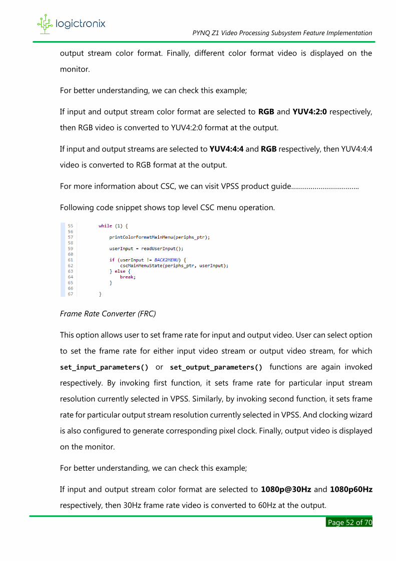
Following code snippet shows top level CSC menu operation.
Frame Rate Converter (FRC)
This option allows user to set frame rate for input and output video. User can select option
to set the frame rate for either input video stream or output video stream, for which
set_input_parameters() or set_output_parameters() functions are again invoked
respectively. By invoking first function, it sets frame rate for particular input stream
resolution currently selected in VPSS. Similarly, by invoking second function, it sets frame
rate for particular output stream resolution currently selected in VPSS. And clocking wizard
is also configured to generate corresponding pixel clock. Finally, output video is displayed
on the monitor.
For better understanding, we can check this example;
If input and output stream color format are selected to 1080p@30Hz and 1080p60Hz
respectively, then 30Hz frame rate video is converted to 60Hz at the output.

PYNQ Z1 Video Processing Subsystem Feature Implementation
Page 53 of 70
For more information about FRC, we can visit VPSS product guide……………………………..
Following code snippet shows top level FRC menu operation.
NOTE: This project design is confined to support 60Hz output video because of test
monitor compatibility. Therefore, user has to write their own codes to support other
output frame rate.
VPSS Report
This is the final main menu option. This option can be used to debug the VPSS. Besides
this, it also give detailed information of configuration of project design. This menu has
four sub menu options, for example,
• VPSS Input/output Configuration
It shows the current VPSS input output stream configuration.
• VPSS Core Information
It shows the sub-cores that are included in under VPSS topology
• VPSS log
It shows all the VPSS event info and error.
• VPSS Mode Status

PYNQ Z1 Video Processing Subsystem Feature Implementation
Page 54 of 70
It shows status of scaling, CSC & FRC.

PYNQ Z1 Video Processing Subsystem Feature Implementation
Page 55 of 70
CHAPTER 3: OUTPUT
After software design is completed, we can now head for implementation of project on PYNQ-
Z1 board. To program the board from computer, we have to set the jumper (JP4) to JTAG mode.
Figure 66. Program jumper setting
Before connecting to computer, we have to check jumper setting (JP5). If we want to power and
program the board by using single mini usb cable, we must change jumper to USB mode. By
then, board is programmed and powered from same computer. We need to power ON the
power, if it is already not done so.
Figure 67. Power jumper setting
After connecting board, we need to prepare software application by building it. If it is successful,
then it can be programmed.
But before launching the application, we can use to Vitis IDE built-in Terminals. We can also use
External Terminals like PuTTY, Tera Term etc…
To add terminal in Vitis IDE, we have to follow steps;
Window > Show View

PYNQ Z1 Video Processing Subsystem Feature Implementation
Page 56 of 70
This opens show view dialog window, where we have to scroll to find Terminal. Then, we need to
expand it to select Terminal and then Open it.
It then adds terminal at bottom-right corner of IDE. We have to connect it with our board. We
also need to configure the terminal.
By clicking on open a terminal icon, it pops-up Launch Terminal dialog window.

PYNQ Z1 Video Processing Subsystem Feature Implementation
Page 57 of 70
Here, we have to choose terminal as Serial Terminal from dropdown options. We need to select
the port, where the board is connected. The port is only visible as long as board is connected to
the computer and it is powered ON. Then we need to choose baud rate. Based on the design,
we can choose one of the baud rates from the dropdown options. This project design uses
115200 baud rate.
After this, we let other parameters as they are already. Then, click on OK to complete terminal
connection.
Now, we can launch the application on board by following steps;
Explorer > Application Project > Right Click > Run as > Launch Hardware
Figure 68. Launching software application on hardware
Vitis IDE first loads the bitstream to board.
Figure 69. Loading bitstream
If it is successful, then launches application on board.

PYNQ Z1 Video Processing Subsystem Feature Implementation
Page 58 of 70
If launching is successful, we might be able to see terminal messages as well as output on the
monitor as following;
Figure 70. Main menu on the terminal
This is what main menu looks like on the terminal. It allows user to select one of these options.
Figure 71. Initial output
This is the output on the monitor, when the project design initially runs with default parameters,
such as,
• Input/output stream (Video Mode): 1920x1080p@60Hz
• Video Pattern : Color bars
• Color format : RGB
• Sampler per Clock : 1
• Frame rate: 60Hz
• Video format: progressive
• Output pixel frequency: 148.5 MHz

PYNQ Z1 Video Processing Subsystem Feature Implementation
Page 59 of 70
Each individual option related output is discussed below
Video Test Pattern
When user selects Test Pattern Selection option, then following menu is seen on the terminal.
Figure 72. Test pattern selection terminal menu
The following sub-menu is seen when change test pattern option is selection.
Figure 73. List of pattern
This menu has lists of various video test pattern. When option is selected, following output is
seen on the monitor.

PYNQ Z1 Video Processing Subsystem Feature Implementation
Page 60 of 70
Figure 74. Different TPG pattern selection output
Scaling
When user selects scaling option from main menu, then following submenu is seen
Figure 75. Scale terminal menu
This messages also displays the current scaling status as highlighted by red box in above image.
From this message, user can select to change the resolution of input stream or output stream.

PYNQ Z1 Video Processing Subsystem Feature Implementation
Page 61 of 70
And following lists of resolution are displayed. Resolution lists are same for input and output
stream.
Figure 76. Resolution list
Followings are scaled outputs are obtained after setting the resolution.
Figure 77. Scaled output from 1080p to 600p
Image represents the output when input stream is at 1920x1080p and output is at 800x600p.
That is, scale down. In other words, 1080p color bar pattern is scaled to fit 600p resolution.

PYNQ Z1 Video Processing Subsystem Feature Implementation
Page 62 of 70
Figure 78. Scaled output from 480p to 720p
Above images depicts the output when both input stream is at 640x480p and output stream is
set to 1280x720p. That is scale up.
Color Space Converter
When user selects Color Space Converter (CSC) options from the main menu, the following CSC
menu is seen on the terminal.
Figure 79. CSC selection terminal menu
There are also two option to select input stream and output stream color format. In meantime,
this menu also displays the current format status between input and output. This is highlighted
by red box in the following image.

PYNQ Z1 Video Processing Subsystem Feature Implementation
Page 63 of 70
Figure 80. Current CSC status of VPSS
This time, both streams have same color format, i.e. RGB. This format can be changed by selecting
menu options.
When one of the options is selected, then following color format list menu is displayed. Color
format lists for both input and output stream are same.
Figure 81. Terminal CSC List
When one of the color formats in chosen, then following outputs obtain.
Figure 82. Output obtained after converting YUV420 into RGB
PYNQ Z1 Video Processing Subsystem Feature Implementation
Page 64 of 70
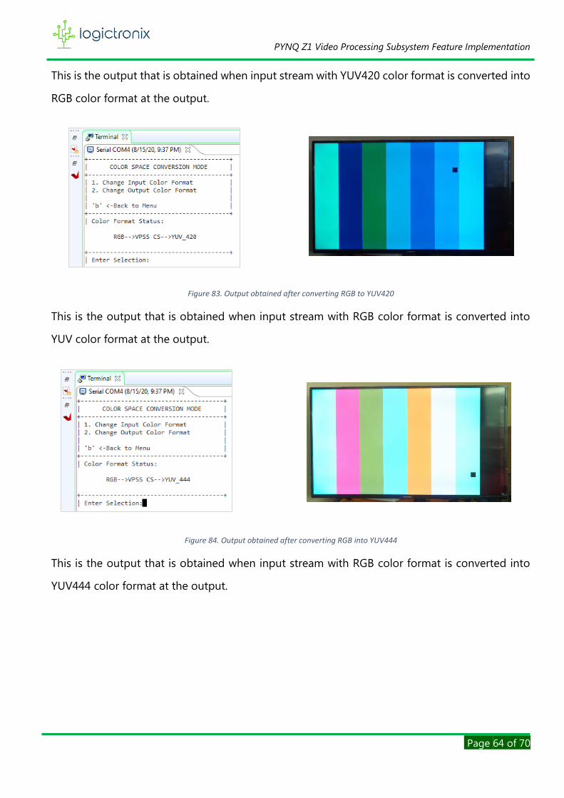
This is the output that is obtained when input stream with YUV420 color format is converted into
RGB color format at the output.
Figure 83. Output obtained after converting RGB to YUV420
This is the output that is obtained when input stream with RGB color format is converted into
YUV color format at the output.
Figure 84. Output obtained after converting RGB into YUV444
This is the output that is obtained when input stream with RGB color format is converted into
YUV444 color format at the output.
PYNQ Z1 Video Processing Subsystem Feature Implementation
Page 65 of 70
Frame Rate Converter (FRC)
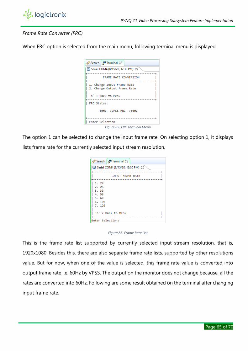
When FRC option is selected from the main menu, following terminal menu is displayed.
Figure 85. FRC Terminal Menu
The option 1 can be selected to change the input frame rate. On selecting option 1, it displays
lists frame rate for the currently selected input stream resolution.
Figure 86. Frame Rate List
This is the frame rate list supported by currently selected input stream resolution, that is,
1920x1080. Besides this, there are also separate frame rate lists, supported by other resolutions
value. But for now, when one of the value is selected, this frame rate value is converted into
output frame rate i.e. 60Hz by VPSS. The output on the monitor does not change because, all the
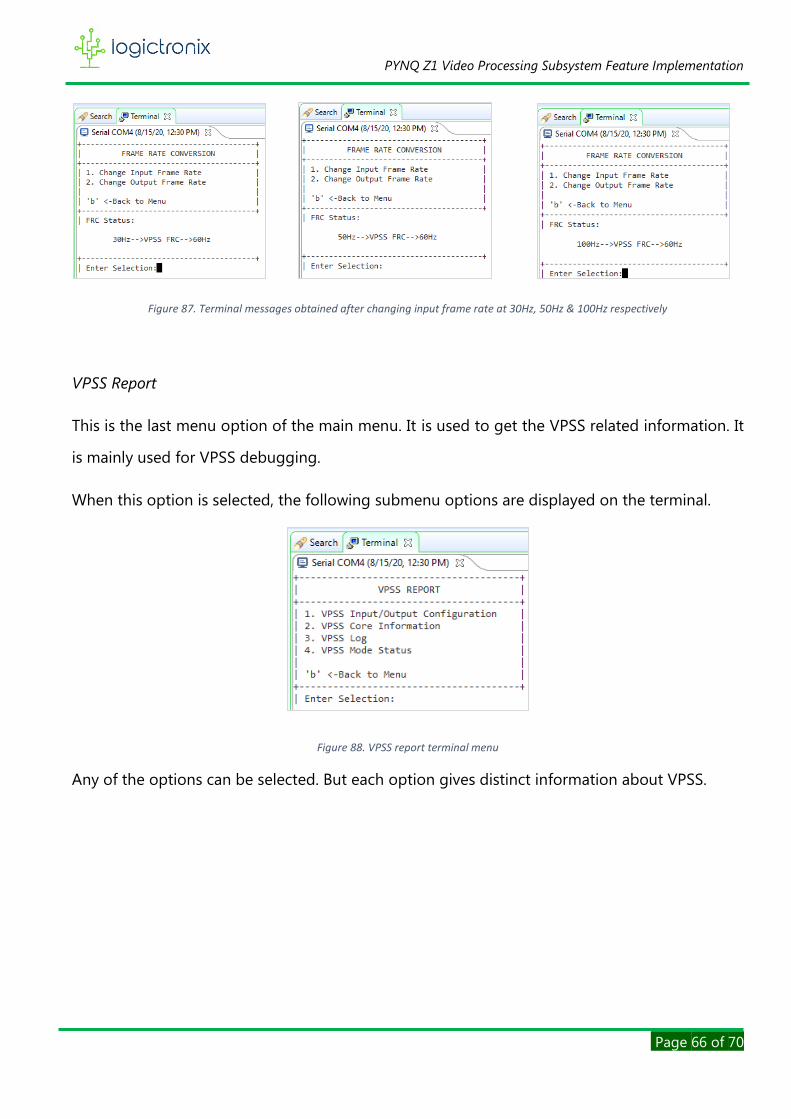
rates are converted into 60Hz. Following are some result obtained on the terminal after changing
input frame rate.
PYNQ Z1 Video Processing Subsystem Feature Implementation
Page 66 of 70
Figure 87. Terminal messages obtained after changing input frame rate at 30Hz, 50Hz & 100Hz respectively
VPSS Report
This is the last menu option of the main menu. It is used to get the VPSS related information. It
is mainly used for VPSS debugging.
When this option is selected, the following submenu options are displayed on the terminal.
Figure 88. VPSS report terminal menu
Any of the options can be selected. But each option gives distinct information about VPSS.
PYNQ Z1 Video Processing Subsystem Feature Implementation
Page 67 of 70
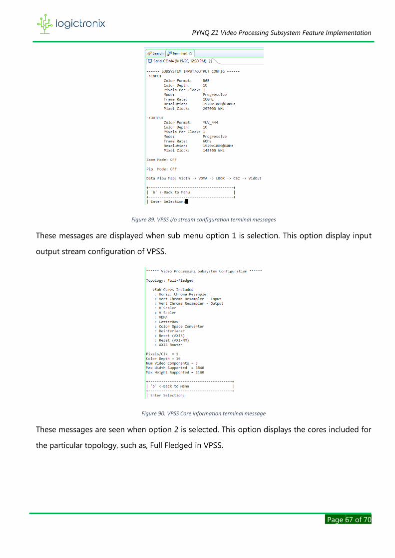
Figure 89. VPSS i/o stream configuration terminal messages
These messages are displayed when sub menu option 1 is selection. This option display input
output stream configuration of VPSS.
Figure 90. VPSS Core information terminal message
These messages are seen when option 2 is selected. This option displays the cores included for
the particular topology, such as, Full Fledged in VPSS.

PYNQ Z1 Video Processing Subsystem Feature Implementation
Page 68 of 70
Figure 91. VPSS log
This is displayed when option 3 is selected. These are event log of VPSS.
Figure 92. VPSS Status
This is displayed when option 4 is selected. This gives information about current scaling status,
color format status and frame rate status of VPSS.

PYNQ Z1 Video Processing Subsystem Feature Implementation
Page 69 of 70
REFERENCES
[1] PYNQ, "PYNQ: PYTHON PRODUCTIVITY," Xilinx, [Online]. Available: http://www.pynq.io/.
[2] L. Swanland, "Python + Zynq = PYNQ : Introducing Our Latest Collaboration!," Digilent,
[Online]. Available: https://blog.digilentinc.com/python-zynq-pynq-introducing-our-
latest-collaboration/.
[3] Xilinx, "Video Processing Subsystem," [Online]. Available:
https://www.xilinx.com/products/intellectual-property/video-processing-subsystem.html.
[4] Xilinx, "Video Test Pattern Generator product guide," xilinx, [Online]. Available:
https://www.xilinx.com/support/documentation/ip_documentation/v_tpg/v8_0/pg103-v-
tpg.pdf.
[5] Xilinx, "Video Processing Subsystem Product Guide," [Online]. Available:
https://www.xilinx.com/support/documentation/ip_documentation/v_proc_ss/v2_0/pg23
1-v-proc-ss.pdf.
[6] xilinx, "Axis subset converter product guide," xilinx, [Online]. Available:
https://www.xilinx.com/support/documentation/ip_documentation/axis_infrastructure_ip
_suite/v1_1/pg085-axi4stream-infrastructure.pdf.
[7] Xilinx, "Clocking Wizard Product Guide," Xilinx, [Online]. Available:
https://www.xilinx.com/support/documentation/ip_documentation/clk_wiz/v6_0/pg065-
clk-wiz.pdf.
[8] xilinx, "video timing controller product guide," xilinx, [Online]. Available:
https://www.xilinx.com/support/documentation/ip_documentation/v_tc/v6_2/pg016_v_tc
.pdf.
Top Related