


Languages
Pages
Legal

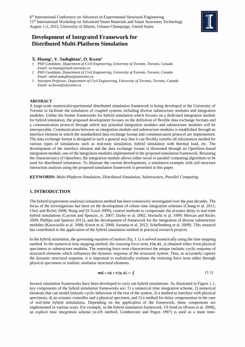
6th International Conference on Advances in Experimental Structural Engineering
11th International Workshop on Advanced Smart Materials and Smart Structures Technology
August 1-2, 2015, University of Illinois, Urbana-Champaign, United States
Development of Integrated Framework for
Distributed Multi-Platform Simulation
X. Huang1, V. Sadeghian2, O. Kwon3 1 PhD Candidate, Department of Civil Engineering, University of Toronto, Toronto, Canada
Email: [email protected]
2 PhD Candidate, Department of Civil Engineering, University of Toronto, Toronto, Canada
Email: [email protected]
3 Assistant Professor, Department of Civil Engineering, University of Toronto, Toronto, Canada
Email: [email protected]
ABSTRACT
A large-scale numerical/experimental distributed simulation framework is being developed at the University of
Toronto to facilitate the simulation of coupled systems including diverse substructure modules and integration
modules. Unlike the former frameworks for hybrid simulation which focuses on a dedicated integration module
for hybrid simulation, the proposed development focuses on the definition of flexible data exchange formats and
a communication protocol through which any potential integration modules and substructure modules will be
interoperable. Communication between an integration module and substructure modules is established through an
interface element in which the standardized data exchange format and communication protocol are implemented.
The data exchange format is designed in such a general way that it can flexibly transfer all information needed for
various types of simulations such as real-time simulation, hybrid simulation with thermal load, etc. The
development of the interface element and the data exchange format is illustrated through an OpenSees-based
integration module, one of the integration modules implemented in the proposed simulation framework. Retaining
the characteristics of OpenSees, the integration module allows either serial or parallel computing algorithms to be
used for distributed simulation. To illustrate the current developments, a simulation example with soil-structure
interaction analysis using the proposed simulation framework is presented in this paper.
KEYWORDS: Multi-Platform Simulation, Distributed Simulation, Substructure, Parallel Computing
1. INTRODUCTION
The hybrid (experiment-analysis) simulation method has been extensively investigated over the past decades. The
focus of the investigations has been on the development of robust time integration schemes (Chang et al. 2011;
Chen and Ricles 2008; Hung and El-Tawil 2009), control methods to compensate the actuator delay in real-time
hybrid simulations (Carrion and Spencer, Jr. 2007; Darby et al. 2002; Horiuchi et al. 1999; Mercan and Ricles
2009; Phillips and Spencer 2012), and the development of framework for the integration of diverse substructure
modules (Karavasilis et al. 2008; Kwon et al. 2008; Saouma et al. 2012; Schellenberg et al. 2009). This research
has contributed to the application of the hybrid simulation method in practical research projects.
In the hybrid simulation, the governing equation of motion (Eq. 1.1) is solved numerically using the time stepping
method. In the numerical time stepping method, the restoring force term, ( , )r u u , is obtained either from physical
specimens or substructure modules. The restoring force term characterizes the unique inelastic cyclic response of
structural elements which influences the dynamic response of the structural system. Thus, to accurately capture
the dynamic structural response, it is important to realistically evaluate the restoring force term either through
physical specimens or realistic nonlinear structural elements.
( , ) mu cu r u u f (1.1)
Several simulation frameworks have been developed to carry out hybrid simulations. As illustrated in Figure 1.1,
key components of the hybrid simulation frameworks are: 1) a numerical time integration scheme, 2) numerical
elements that can model inelastic cyclic behaviour of the rest of the system, 3) a method to interface with physical
specimens, 4) an actuator controller and a physical specimen, and 5) a method for delay compensation in the case
of real-time hybrid simulations. Depending on the application of the framework, these components are
implemented in various ways. For example, in the hybrid simulation framework, UI-SimCor (Kwon et al. 2008),
an explicit time integration scheme (α-OS method, Combescure and Pegon 1997) is used as a main time-

integration scheme. The restoring forces from physical specimens or substructure modules are obtained through
the computer network. The experimental facility is expected to have an ability to generate ramp and execute the
displacement command from UI-SimCor. The framework has been applied to many hybrid simulations because
it is open source, and also allows integration of diverse substructure elements. Yet, because all restoring forces
are obtained from substructure modules through the computer network, the framework suffers from an increase
in network traffic and computing time when a large number of degrees of freedoms are used in the simulation.
OpenSees (Mazzoni et al. 2007) is an open source seismic analysis tool with many unique inelastic structural
elements. The software also has been used in many hybrid simulations. OpenSees is a self-contained analysis tool
which includes time integration schemes and numerical elements. A middleware which is termed as OpenFresco
(Schellenberg et al. 2009) is used to communicate with actuator controllers. Other frameworks, such as Hybrid
FEM (Karavasilis et al. 2008) or Mercury (Saouma et al. 2012) implement nonlinear structural elements, and are
aimed at running real-time simulations.
Figure 1.1 Components of the hybrid simulation framework
The basis of the hybrid simulation method is very similar to the substructure analysis method in which a large
structural system is partitioned into multiple smaller substructures, each of which is analyzed separately. The
substructure analysis method has been mainly used to partition a large structural system with smaller substructures
such that distributed computational resources can be used. A major difference between the hybrid (experiment-
analysis) simulation and the substructure analysis method is that at least one substructure is represented as a
physical specimen. In addition, unlike purely numerical substructure analyses, the hybrid simulation does not
allow iterations within a time step. This feature, however, is beneficial when integrating numerical models from
different analysis tools. Because of legacy or intellectual property issues, it is very difficult to rewrite and integrate
models from multiple analysis tools, such as Abaqus (Hibbit et al. 2001), OpenSees (Mazzoni et al. 2007), VecTor
(Wong and Vecchio 2002), or Ansys. If the hybrid simulation method is extended for numerical substructure
simulation, a complex structural system, such as the soil-foundation-structure system or a structure with shear-
critical reinforced concrete elements, can be analyzed more accurately by modelling each component with a more
appropriate tool for the component and by integrating them.
The key requirement for such integration is a standardized data exchange format and a communication protocol
through which any numerical analysis tool can integrate other numerical or physical models. This will allow for
maximizing the use of available analysis tools and the use of computational and experimental resources. The main
objective of the research presented in this paper is to develop a standardized data exchange format which can
greatly facilitate integration of diverse numerical analysis tools and physical specimens. In Section 2, the overall
architecture of the integrated simulation is presented. The architecture does not propose (or oppose) the use of one
analysis tool for the integrated simulation. Rather, it shows how diverse tools can be integrated by using the
proposed data exchange format and its implementation. In Section 3, two analysis examples are presented,
followed by the conclusions in Section 4.
2. INTEGRATED SIMULATION METHOD
2.1 Overall Architecture
At any given time step, the numerical integration scheme (Component 1 in Figure 1.1), assembles a global force
vector from the numerical elements, and solves for the unknown state variables (i.e., displacement, velocity, and
Numerical substructure elements
Physically
represented
Middleware for controller
Numerical
model
Physical substructure element
PID loop
Numerical integration
scheme
Component #1 Component #2
Component #3Component #4
Controller

acceleration vectors) in the time step. Depending on the nonlinear solution scheme, it might be necessary to
assemble a global tangent stiffness matrix. The numerical elements may require predicted displacements and/or
velocities to return force vectors and stiffness matrices. By collecting the force vectors and stiffness matrices from
different numerical elements or analysis tools at each time step, it is possible to find unknown state variables and
move on to the next time step. A main functionality that is required for this integration is the communication
between numerical models (or analysis tools) at each time step and the numerical integration scheme.
In this study, a few assumptions are made to integrate diverse structural analysis tools. First, it is assumed that all
substructure modules are either displacement or velocity dependent, and they do not have their own mass. This
assumption simplifies the integration of various components; if the substructure represents a mass-damper-spring
system, then each substructure module needs to run dynamic analyses which can introduce stability issues in the
dynamic integration scheme. This issue was observed in the dynamic soil-structure-interaction analysis in which
the soil-foundation system is modelled based on dynamic impedance functions (Lesgidis et al. 2015). Based on
the assumption, one can classify the analysis tools with two components: 1) an integration module which runs
time integration schemes with the numerical model of majority of structural systems (Component #1 and #2 in
Figure 1.1), and 2) static substructure modules which run static analysis or experiment (Component #3 and #4 in
Figure 1.1). The second assumption is that the nonlinear solution scheme in the integration module does not take
a trial and error approach. Depending on the nonlinear solution scheme, an incremental displacement is tried and
cancelled later on, if necessary, to try a smaller incremental displacement. This method is frequently used when
the model cannot converge to a solution in a time step. This method, however, is not applicable to experimental
elements or to a substructure element modelled in a different analysis tool. Thus, at this stage, it is assumed that
the integration module runs a non-iterative explicit time integration scheme.
Figure 2.1 Integration and substructure modules
With the two assumptions in the above, any large structural system can be analyzed by integrating more than one
analysis tool, including an integration module and substructure modules. Once one of the substructure modules
are replaced with a physical specimen, then it becomes a hybrid (experiment-analysis) simulation. Otherwise, the
analysis becomes a multi-platform simulation. Several integration and substructure modules can be integrated
together using the above framework. The current development is illustrated in Figure 2.1. The authors
implemented standardized communication functionality in the following integration modules: UI-SimCor (Kwon
et al. 2008), Cyrus (Sadeghian et al. 2015a; b), and OpenSees and OpenSeesSP (Mazzoni et al. 2007). Cyrus has
been developed as a main integration module for VecTor programs which specialize in analyzing reinforced
concrete structures based on Modified Compression Field Theory and Disturbed Stress Model (Vecchio and
Collins 1986; Vecchio 2000). In addition to integrating the VecTor programs, a research is in progress to use
Cyrus as a main integration module for other substructure modules including physical specimens. If the majority
of the structural system is made of reinforced concrete, then Cyrus is expected to be most reliable analysis tool.
To use OpenSees and OpenSeesSP as a main integration module, a SubStructure element in the program is
modified such that it can collect the substructure model’s restoring force and stiffness matrix through the network.
In addition, the port tunnelling method is used such that OpenSeesSP operating in a SciNet supercomputer can
OpenSeesCluster or Dekstop
Subs.Elem.
Zeus-NL
Abaqus
VecTor 2, 3, 4, and 5
Actuators, MAST, UT10 Simulator
OpenSees
UI-SimCor v3.0
DesktopNICON
NICA
NICA
Integration Modules
Numerical Substructure Modules
Voltage
Named pipes
UTNP via TCP-IP
Cyrus
NICA
Experimental Substructure Modules
Communication Methods
S-Frame(in progress)
Abaqus(in progress)
Soil-Foundation System(in progress)

communicate with a substructure module in a desktop computer or with a physical specimen. This feature will
allow simulation of a large soil-structure system with most reliable analysis tools and large computing power. In
collaboration with an industry partner, a research project is in progress to use the S-Frame commercial
design/analysis software as an integration module, which will facilitate the use of advanced analysis methods in
the design process.
Several substructure modules can be integrated with the integration modules. For now, the following analysis
tools can be used as substructure modules: OpenSees, VecTor programs, Zeus-NL (Elnashai et al. 2002), Abaqus,
and experimental elements. It is worth noting that OpenSees and Abaqus can be used both as integration and
substructure modules. To interface an experimental element, a unique middleware program, NICON, is developed
which can serve as an interface for up to six coupled DOFs or for up to ten uncoupled DOFs (Zhan and Kwon
2015).
The main requirement for the interoperability between diverse substructure and integration modules is a unified
data exchange format and communication protocol. In addition, each substructure module should have a
functionality to impose the predicted displacement to the numerical or physical model. Each integration module
should have a functionality to collect a force vector or a stiffness matrix from the substructure module as well. In
the next subsection, a standardized data exchange format and its implementation are introduced.
2.2 Standardized Data Exchange Format
To efficiently integrate diverse substructure modules, it is essential to use a standardized data exchange format.
While there have been extensive research projects on hybrid simulation methods, the simulation frameworks have
their own communication method or data exchange format. There were attempts to develop a standardized
communication protocol, NEESgrid Teleoperations Control Protocol (NTCP, Pearlman et al. 2004) and NEES
Hybrid Communications Protocol (NHCP, Cowart et al. 2007) with the support of the NEES program. NHCP is
a successor of NTCP, intended to overcome the limitations of the NTCP. Up to the extent of the authors’
knowledge, however, implementation and application of the NHCP protocol in hybrid simulations is limited.
NHCP includes many useful functionalities which can ensure secure transmission of data packets.
To allow communication between two modules, it is necessary to define the data exchange format and the
communication protocol. Because all data communicated through the network is serialized, both sides should
understand how arrays or vectors are serialized, and what type of data is included in the packet. In addition, both
sides also need to agree on the sequence of data exchange because when one side sends data, the other side should
receive and process the data. In the current implementation, it is assumed that the integration module sends a
command and the substructure module responds to the command. Thus, the protocol is rather straight forward.
This protocol can be improved in future implementations by allowing multiple channels of communication, or by
using UDP instead of TCP-IP to allow faster (yet somewhat unreliable) communication. Further development of
communication protocols is left for a later study. The following discussion is mainly concerned with the
standardized data exchange format.
The University of Toronto Networking Protocol (UTNP) data exchange format consists of a header and
corresponding data. All data is exchanged in binary to reduce the packet size, not to lose accuracy during the
binary-ASCII conversion process, nor to waste processing time during the conversion process. The header consists
of 16 total bytes of data as illustrated in Figure 2.2. Specifically, the version parameter indicates the version of
the data exchange format for the purpose of maintenance. The command parameter indicates the communication
action which can be sending target displacement to the substructures or asking them for restoring forces. The test
type parameter indicates whether the simulation is pseudo-dynamic or real-time. The substructure type describes
the type of the substructure used in the simulation which can be either numerical or experimental. The precision
parameter defines the precision of data appended to the message header. The data type indicates the type of the
appended data, either displacement, force, velocity, acceleration, temperature, or any combination thereof. The
size of the header is fixed to be 16 bytes while the size of the corresponding data depends on the parameters
defined in the message header. For example, if an experimental two-dimensional truss element is represented, the
Number of DOF parameters is 4 (the total number of DOFs of the substructure), the command parameter is 3
(sending target displacements to the substructure), and the precision parameter is 2 (double precision, 8 bytes).
The size of the data appended to the message header will be set to be 32 bytes (4 DOFs × 8 bytes) for target
displacements. More details on the data exchange format will be released to the research community in upcoming
publications.

Figure 2.2 The data exchange format in UTNP
To facilitate the implementation of the above data exchange format, the authors developed a set of functions which
can be used to send and receive data packets using the above data exchange format. A dynamic link library (DLL)
is compiled with the functions, which has been tested with C++ for OpenSees and OpenSeesSP, FORTRAN for
VecTor2, MATLAB for UI-SimCor, and LabView for NICON. Most of the data exchange in Figure 2.1 is carried
out using the data exchange format. Once the robustness of the data exchange function is fully tested, the library
will be open to the research community such that any other research groups can develop their own integration or
substructure modules, which can work together with all the modules illustrated in Figure 2.1.
3. VERIFICATION EXAMPLES
3.1 A Frame with Shear- and Flexure-critical Columns (OpenSees and VecTor2)
Two verification examples are presented in this paper to illustrate current developments. The first example is a
shaking table test of a three bay frame tested by Wu et al. (2009). The specimen consists of two shear-critical and
two flexure-critical columns. The columns are fixed at the bottom to supports at the top to a stiff beam. All four
columns have the same aspect ratio but different reinforcement details are used to obtain both shear and flexural
failure modes. A total of 22.7 tonnes of weight, including the weight of the beam, are placed to simulate gravity
load and inertial mass. As shown in Figure 3.1, one shear-critical column of the structure is modelled as a
substructure with VecTor2 while the rest of the structure is modelled with OpenSees acting as an integration
module. For the OpenSees model, all masses are lumped at the beam-column joints, which are assumed to be
rigid. Each component is represented with one force-based beam column element with five integration points.
Rayleigh damping is used with a damping ratio of 1.8% at the natural period of the structure. For the VecTor2
model, concrete and longitudinal reinforcement is represented by rectangular continuum elements and discrete
truss elements, respectively. Out-of-plane and in-plane transverse reinforcements are smeared over the concrete
core. To accurately simulate the interface between frame elements and continuum elements, frame elements with
three DOFs per node and continuum elements with two DOFs per node are connected through rigid beam elements
as shown in Figure 3.1. Figure 3.2 compares time histories of inter-story drifts measured from experiments and
results from the numerical model. From this figure it can be found that the numerical model underestimates the
displacement response. One potential reason for this would be modelling of the top beam as rigid which may not
properly re-distribute the axial loads to columns after failure. Figure 3.3 shows the deformed shape of the structure
and crack pattern of the shear-critical column modelled with VecTor2 at the maximum lateral displacement
Figure 3.1 Numerical models of the tested frame
Version Command Test type Substructure type
Precision Data type Number of DOFs
Step number Reserved for future extension
Time stamp
Data
32 bit
16 bytes
Size depends
on header
Truss elements
for rebars
Core concrete
Cover concreteRigid elements
Frame elementsLumped masses
OpenSees model VecTor2 model
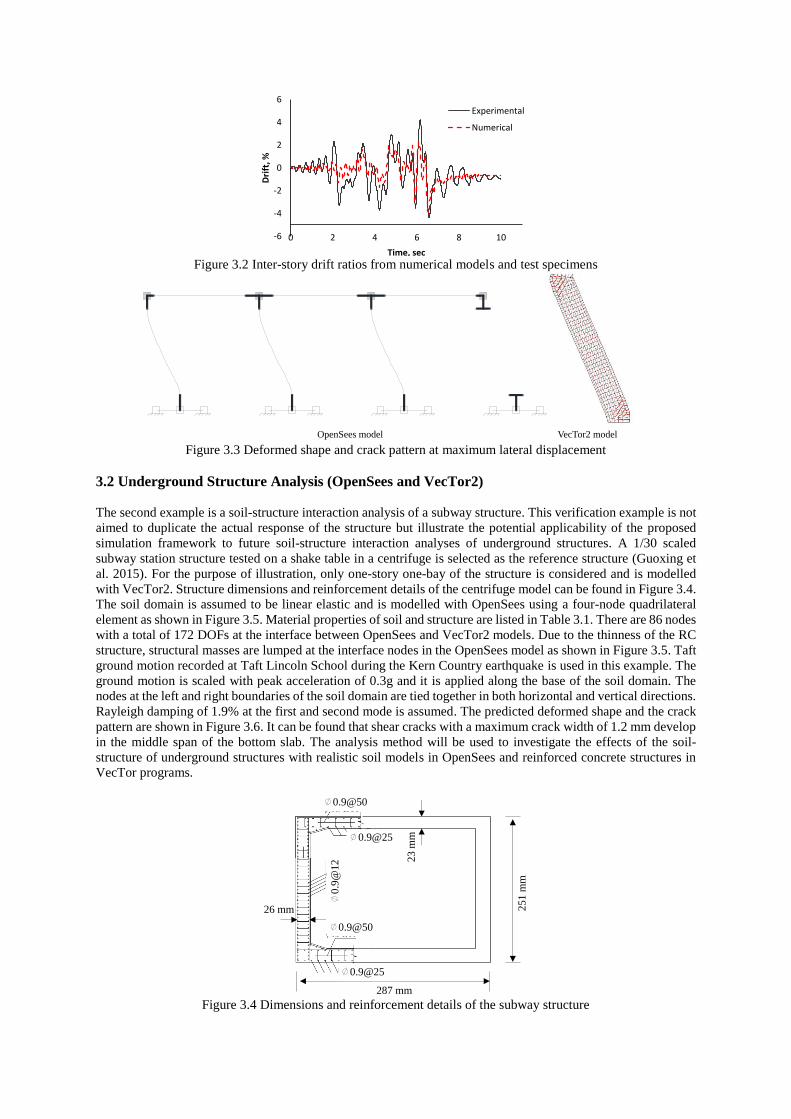
Figure 3.2 Inter-story drift ratios from numerical models and test specimens
Figure 3.3 Deformed shape and crack pattern at maximum lateral displacement
3.2 Underground Structure Analysis (OpenSees and VecTor2)
The second example is a soil-structure interaction analysis of a subway structure. This verification example is not
aimed to duplicate the actual response of the structure but illustrate the potential applicability of the proposed
simulation framework to future soil-structure interaction analyses of underground structures. A 1/30 scaled
subway station structure tested on a shake table in a centrifuge is selected as the reference structure (Guoxing et
al. 2015). For the purpose of illustration, only one-story one-bay of the structure is considered and is modelled
with VecTor2. Structure dimensions and reinforcement details of the centrifuge model can be found in Figure 3.4.
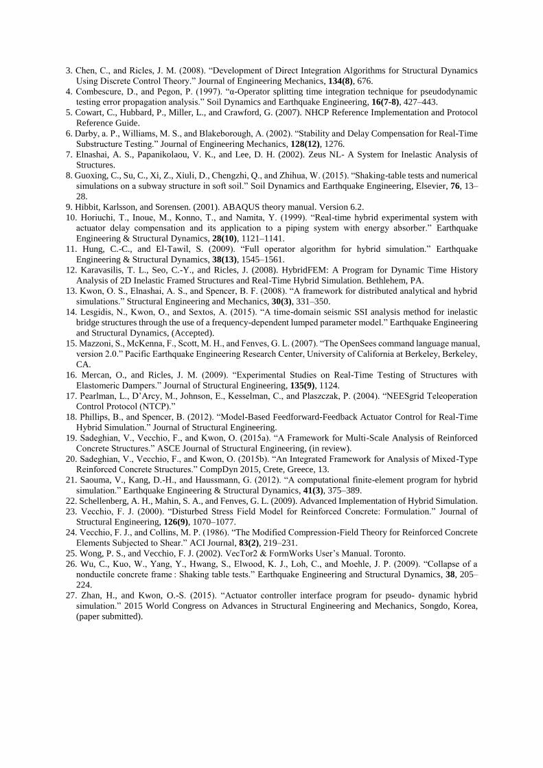
The soil domain is assumed to be linear elastic and is modelled with OpenSees using a four-node quadrilateral
element as shown in Figure 3.5. Material properties of soil and structure are listed in Table 3.1. There are 86 nodes
with a total of 172 DOFs at the interface between OpenSees and VecTor2 models. Due to the thinness of the RC
structure, structural masses are lumped at the interface nodes in the OpenSees model as shown in Figure 3.5. Taft
ground motion recorded at Taft Lincoln School during the Kern Country earthquake is used in this example. The
ground motion is scaled with peak acceleration of 0.3g and it is applied along the base of the soil domain. The
nodes at the left and right boundaries of the soil domain are tied together in both horizontal and vertical directions.
Rayleigh damping of 1.9% at the first and second mode is assumed. The predicted deformed shape and the crack
pattern are shown in Figure 3.6. It can be found that shear cracks with a maximum crack width of 1.2 mm develop
in the middle span of the bottom slab. The analysis method will be used to investigate the effects of the soil-
structure of underground structures with realistic soil models in OpenSees and reinforced concrete structures in
VecTor programs.
Figure 3.4 Dimensions and reinforcement details of the subway structure
-6
-4
-2
0
2
4
6
0 2 4 6 8 10
Dri
ft, %
Time, sec
Experimental
Numerical
OpenSees model VecTor2 model
287 mm
25
1 m
m
23
mm
26 mm
∅0.9@50
∅0.9@25
∅0
.9@
12
∅0.9@50
∅0.9@25
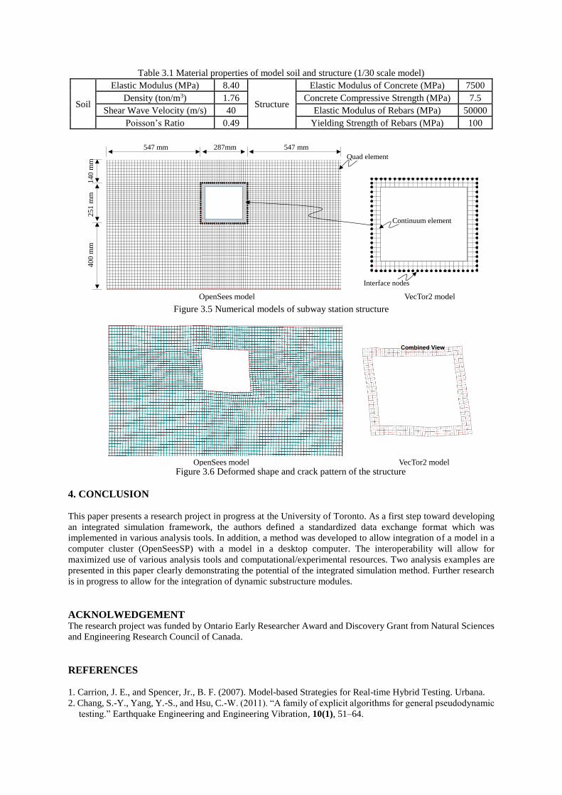
Table 3.1 Material properties of model soil and structure (1/30 scale model)
Soil
Elastic Modulus (MPa) 8.40
Structure
Elastic Modulus of Concrete (MPa) 7500
Density (ton/m3) 1.76 Concrete Compressive Strength (MPa) 7.5
Shear Wave Velocity (m/s) 40 Elastic Modulus of Rebars (MPa) 50000
Poisson’s Ratio 0.49 Yielding Strength of Rebars (MPa) 100
Figure 3.5 Numerical models of subway station structure
Figure 3.6 Deformed shape and crack pattern of the structure
4. CONCLUSION
This paper presents a research project in progress at the University of Toronto. As a first step toward developing
an integrated simulation framework, the authors defined a standardized data exchange format which was
implemented in various analysis tools. In addition, a method was developed to allow integration of a model in a
computer cluster (OpenSeesSP) with a model in a desktop computer. The interoperability will allow for
maximized use of various analysis tools and computational/experimental resources. Two analysis examples are
presented in this paper clearly demonstrating the potential of the integrated simulation method. Further research
is in progress to allow for the integration of dynamic substructure modules.
ACKNOLWEDGEMENT The research project was funded by Ontario Early Researcher Award and Discovery Grant from Natural Sciences
and Engineering Research Council of Canada.
REFERENCES
1. Carrion, J. E., and Spencer, Jr., B. F. (2007). Model-based Strategies for Real-time Hybrid Testing. Urbana.
2. Chang, S.-Y., Yang, Y.-S., and Hsu, C.-W. (2011). “A family of explicit algorithms for general pseudodynamic
testing.” Earthquake Engineering and Engineering Vibration, 10(1), 51–64.
OpenSees model VecTor2 model
Continuum element
Quad element
Interface nodes
14
0 m
m2
51
mm
40
0 m
m
547 mm 287mm 547 mm
OpenSees model VecTor2 model
3. Chen, C., and Ricles, J. M. (2008). “Development of Direct Integration Algorithms for Structural Dynamics
Using Discrete Control Theory.” Journal of Engineering Mechanics, 134(8), 676.
4. Combescure, D., and Pegon, P. (1997). “α-Operator splitting time integration technique for pseudodynamic
testing error propagation analysis.” Soil Dynamics and Earthquake Engineering, 16(7-8), 427–443.
5. Cowart, C., Hubbard, P., Miller, L., and Crawford, G. (2007). NHCP Reference Implementation and Protocol
Reference Guide.
6. Darby, a. P., Williams, M. S., and Blakeborough, A. (2002). “Stability and Delay Compensation for Real-Time
Substructure Testing.” Journal of Engineering Mechanics, 128(12), 1276.
7. Elnashai, A. S., Papanikolaou, V. K., and Lee, D. H. (2002). Zeus NL- A System for Inelastic Analysis of
Structures.
8. Guoxing, C., Su, C., Xi, Z., Xiuli, D., Chengzhi, Q., and Zhihua, W. (2015). “Shaking-table tests and numerical
simulations on a subway structure in soft soil.” Soil Dynamics and Earthquake Engineering, Elsevier, 76, 13–
28.
9. Hibbit, Karlsson, and Sorensen. (2001). ABAQUS theory manual. Version 6.2.
10. Horiuchi, T., Inoue, M., Konno, T., and Namita, Y. (1999). “Real-time hybrid experimental system with
actuator delay compensation and its application to a piping system with energy absorber.” Earthquake
Engineering & Structural Dynamics, 28(10), 1121–1141.
11. Hung, C.-C., and El-Tawil, S. (2009). “Full operator algorithm for hybrid simulation.” Earthquake
Engineering & Structural Dynamics, 38(13), 1545–1561.
12. Karavasilis, T. L., Seo, C.-Y., and Ricles, J. (2008). HybridFEM: A Program for Dynamic Time History
Analysis of 2D Inelastic Framed Structures and Real-Time Hybrid Simulation. Bethlehem, PA.
13. Kwon, O. S., Elnashai, A. S., and Spencer, B. F. (2008). “A framework for distributed analytical and hybrid
simulations.” Structural Engineering and Mechanics, 30(3), 331–350.
14. Lesgidis, N., Kwon, O., and Sextos, A. (2015). “A time-domain seismic SSI analysis method for inelastic
bridge structures through the use of a frequency-dependent lumped parameter model.” Earthquake Engineering
and Structural Dynamics, (Accepted).
15. Mazzoni, S., McKenna, F., Scott, M. H., and Fenves, G. L. (2007). “The OpenSees command language manual,
version 2.0.” Pacific Earthquake Engineering Research Center, University of California at Berkeley, Berkeley,
CA.
16. Mercan, O., and Ricles, J. M. (2009). “Experimental Studies on Real-Time Testing of Structures with
Elastomeric Dampers.” Journal of Structural Engineering, 135(9), 1124.
17. Pearlman, L., D’Arcy, M., Johnson, E., Kesselman, C., and Plaszczak, P. (2004). “NEESgrid Teleoperation
Control Protocol (NTCP).”
18. Phillips, B., and Spencer, B. (2012). “Model-Based Feedforward-Feedback Actuator Control for Real-Time
Hybrid Simulation.” Journal of Structural Engineering.
19. Sadeghian, V., Vecchio, F., and Kwon, O. (2015a). “A Framework for Multi-Scale Analysis of Reinforced
Concrete Structures.” ASCE Journal of Structural Engineering, (in review).
20. Sadeghian, V., Vecchio, F., and Kwon, O. (2015b). “An Integrated Framework for Analysis of Mixed-Type
Reinforced Concrete Structures.” CompDyn 2015, Crete, Greece, 13.
21. Saouma, V., Kang, D.-H., and Haussmann, G. (2012). “A computational finite-element program for hybrid
simulation.” Earthquake Engineering & Structural Dynamics, 41(3), 375–389.
22. Schellenberg, A. H., Mahin, S. A., and Fenves, G. L. (2009). Advanced Implementation of Hybrid Simulation.
23. Vecchio, F. J. (2000). “Disturbed Stress Field Model for Reinforced Concrete: Formulation.” Journal of
Structural Engineering, 126(9), 1070–1077.
24. Vecchio, F. J., and Collins, M. P. (1986). “The Modified Compression-Field Theory for Reinforced Concrete
Elements Subjected to Shear.” ACI Journal, 83(2), 219–231.
25. Wong, P. S., and Vecchio, F. J. (2002). VecTor2 & FormWorks User’s Manual. Toronto.
26. Wu, C., Kuo, W., Yang, Y., Hwang, S., Elwood, K. J., Loh, C., and Moehle, J. P. (2009). “Collapse of a
nonductile concrete frame : Shaking table tests.” Earthquake Engineering and Structural Dynamics, 38, 205–
224.
27. Zhan, H., and Kwon, O.-S. (2015). “Actuator controller interface program for pseudo- dynamic hybrid
simulation.” 2015 World Congress on Advances in Structural Engineering and Mechanics, Songdo, Korea,
(paper submitted).
Top Related