


Languages
Pages
Legal


iNEMI Confidential
for member organization use only
Development of cleanliness
specification for lens-based
TOSA/ROSA
iNEMI F2F
OFC/NFOEC 2012
Mar 5, 2012
1 iNEMI Confidential
for member organization use only
Project Contributors
•Glenn Victor
•Doug Wilson & Tom Mictheltree
•Tatiana Berdinskikh
•Mark Marino
•Toshiaki Satake
•Ed Stuart
•David Lach

2 iNEMI Confidential
for member organization use only
Presentation Outline
•Background
•Project Challenges
•Different technologies of TOSA/ROSA
•Synthetic Defects Experiments
•Initial data on impact of contamination on optical performance of lens-based SFPs
•Next steps
3 iNEMI Confidential
for member organization use only
Introduction
• No industry specification for lens-based TOSA/ROSA
• Sumitomo collected data on OC-48 SFPs in 2005-2007 • iNEMI team combined modeling and experimental data (2008-
2009) to study contamination effects on lens-based devices
– 10G SFP+ Sumitomo transceiver was used a test vehicle for the project
– Paper has been published at OFC/NFOEC09 conference ( San Diego, CA, Mar, 09)
• Further research is required for development of cleanliness specification of lens-based receptacles

4 iNEMI Confidential
for member organization use only 4
Pluggable Optics – Common MSA Package Types
SNAP12 MSA
Parallel Optic Device
5 iNEMI Confidential
for member organization use only
Challenges
•Multiple designs of lens-based transceivers in use
–The collaboration efforts between different module
manufactures, CMs and OEMs are required
•Difficult contamination techniques
– Manual process with low repeatability and reproducibility
•Cleaning process of lens-based receptacles is challenging
due to limited access to lens surface
6 iNEMI Confidential
for member organization use only
ROSA/TOSA Technologies
• Many different internal structures within OSA devices have been
discovered
• The differences, amongst multiple suppliers, create a huge
challenge for defining inspection and cleaning requirements
• Several of these designs are shown in next slides
7 iNEMI Confidential
for member organization use only
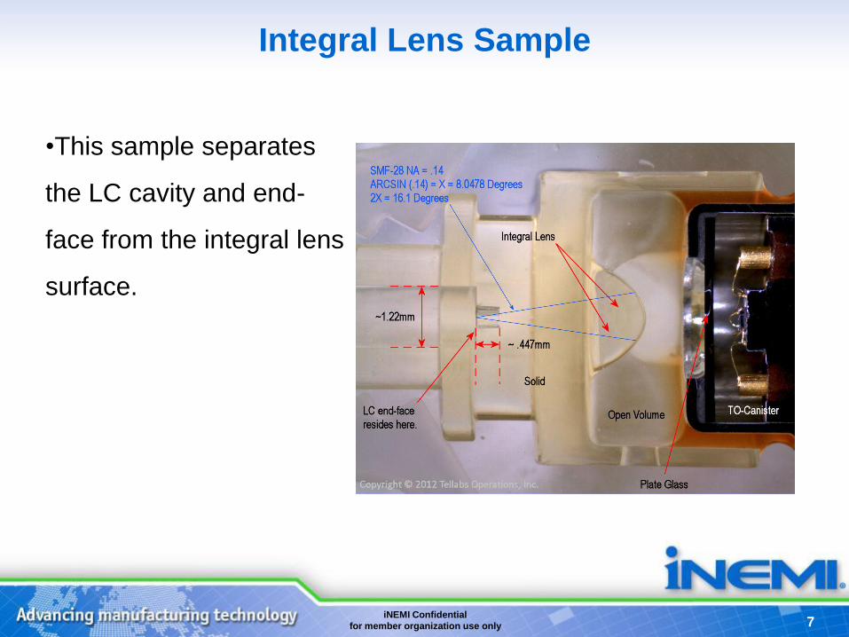
Integral Lens Sample
•This sample separates
the LC cavity and end-
face from the integral lens
surface.

8 iNEMI Confidential
for member organization use only
Multiple lens Sample
•This sample utilizes a
“Contact Type” lens that
makes physical contact
with the LC end-face.
•The lens floats, and is
not hermetically sealed
within the OSA structure.
•Cleaning of the contact
flat lens is practical.
9 iNEMI Confidential
for member organization use only
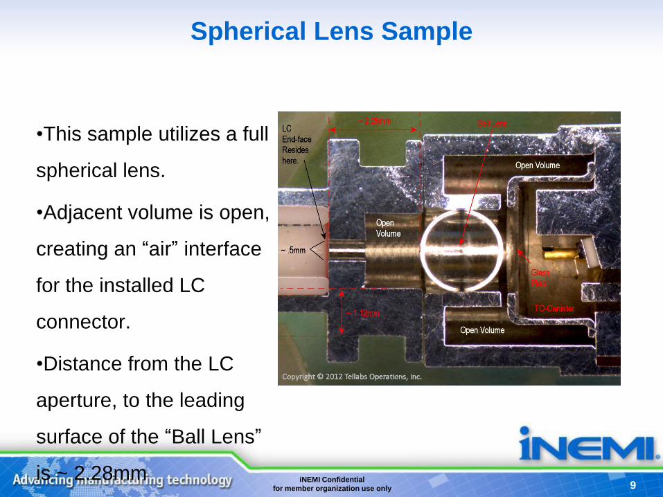
Spherical Lens Sample
•This sample utilizes a full
spherical lens.
•Adjacent volume is open,
creating an “air” interface
for the installed LC
connector.
•Distance from the LC
aperture, to the leading
surface of the “Ball Lens”
is ~ 2.28mm
10 iNEMI Confidential
for member organization use only
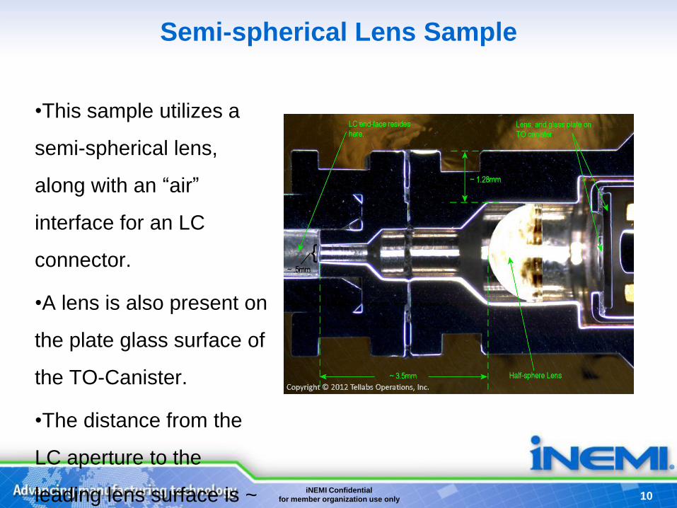
Semi-spherical Lens Sample
•This sample utilizes a
semi-spherical lens,
along with an “air”
interface for an LC
connector.
•A lens is also present on
the plate glass surface of
the TO-Canister.
•The distance from the
LC aperture to the
leading lens surface is ~

11 iNEMI Confidential
for member organization use only
Semi-spherical Lens Close to Aperture Sample
•This sample represents
a structure where the
semi-spherical lens
surface is near the LC
aperture.
•Open volume surrounds
the lens
•The distance from the
LC aperture to the
leading lens surface is ~
1.31mm.

12 iNEMI Confidential
for member organization use only
Sophisticated Structures Sample
•Sophisticated structures,
and optical components,
other than lenses, may
reside.
•This structure includes
what is believed to be an
isolator, within the optical
path.
•As the isolator emerging
surface is angled,
cleaning and inspection
13 iNEMI Confidential
for member organization use only
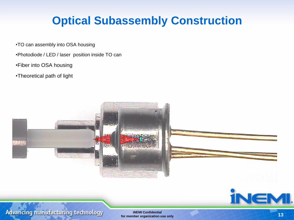
Optical Subassembly Construction
•TO can assembly into OSA housing
•Photodiode / LED / laser position inside TO can
•Fiber into OSA housing
•Theoretical path of light

14 iNEMI Confidential
for member organization use only 14
Transceiver De-construction for Testing
SFP transceiver with lens-based transmitter and receiver

15 iNEMI Confidential
for member organization use only 15
Transceiver de-construction for testing
• Cutaways made in metal housing to expose lens without affecting the optical
transmission
• Facilitates easy contamination and re-cleaning.
• Maybe re-assembled back into the module for performance testing.
16 iNEMI Confidential
for member organization use only 16
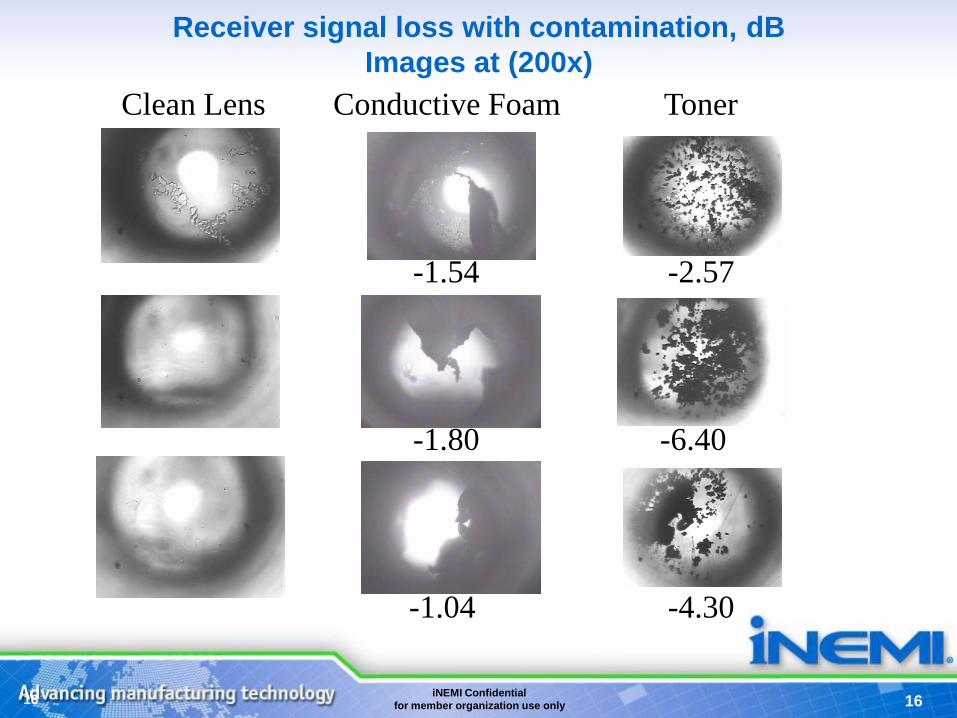
Receiver signal loss with contamination, dB
Images at (200x)
-1.04
-1.80
-1.54
Conductive Foam
-4.30
-6.40
-2.57
Toner Clean Lens
17 iNEMI Confidential
for member organization use only
DOE for Controlled Blockage
•Measure output power with no interference
•Use microscope to measure active area of lens
•Capture image of synthetic defect at each pre-defined
measurement location (X and Y) with XMTR ON and OFF
•Reconnect to power meter, move to each XY location, and
measure output power
•Plot output power in 2D intensity graph for analysis
•Repeat for each defect type
Using Synthetic Defects
18 iNEMI Confidential
for member organization use only
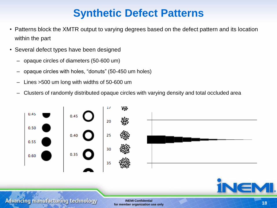
Synthetic Defect Patterns
• Patterns block the XMTR output to varying degrees based on the defect pattern and its location
within the part
• Several defect types have been designed
– opaque circles of diameters (50-600 um)
– opaque circles with holes, “donuts” (50-450 um holes)
– Lines >500 um long with widths of 50-600 um
– Clusters of randomly distributed opaque circles with varying density and total occluded area
19 iNEMI Confidential
for member organization use only
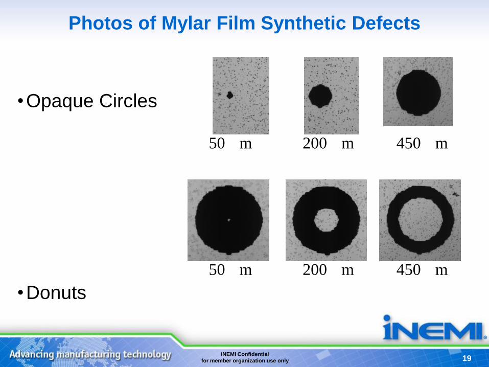
Photos of Mylar Film Synthetic Defects
•Opaque Circles
•Donuts
50 m 200 m 450 m
50 m 200 m 450 m
20 iNEMI Confidential
for member organization use only
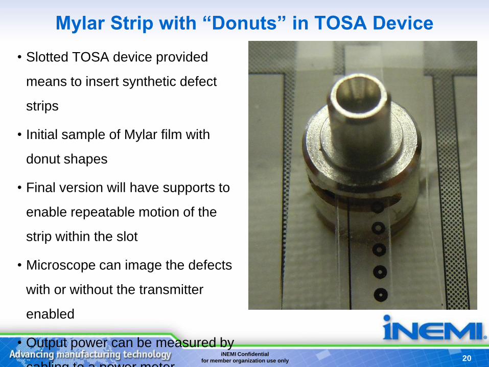
Mylar Strip with “Donuts” in TOSA Device
• Slotted TOSA device provided
means to insert synthetic defect
strips
• Initial sample of Mylar film with
donut shapes
• Final version will have supports to
enable repeatable motion of the
strip within the slot
• Microscope can image the defects
with or without the transmitter
enabled
• Output power can be measured by
cabling to a power meter

21 iNEMI Confidential
for member organization use only
Initial Images of Synthetic Defects
• Transmitter was ON, which is source of circle of light.
• Top row is 265 um defect, lower row defect is ~540 um in dia
• Illuminated area is ~600 um in diameter, as viewed through the aperture in device.
• Size of defects and transmitter circle are both increased by same proportion, most likely correct for separation distance from
device.
• Roughness at edge of circle is defocusing of the sharp edge of the aperture
22 iNEMI Confidential
for member organization use only
TOSA Focus Journey
• Movie not included in this version
23 iNEMI Confidential
for member organization use only
TOSA Synthetic Defects
• Movie not included in this version

24 iNEMI Confidential
for member organization use only
Preliminary Power Readings
• Quick readings were made of output power as a synthetic defect
strip was randomly move around
• Observed about 20-25 dB decrease in output power as large circle
was moved into the main path
• While not a controlled experiment, it was encouraging to see the
defect quench the output as expected
• Next step is carefully controlled motion with quantitative measure
of occlusion to match with output power measurements
25 iNEMI Confidential
for member organization use only
Next Steps
• Collect additional images and associated optical performance data
on contaminated samples
• Conduct controlled synthetic defect experiment to quantify
relationship between occluded area and optical performance
• Optical performance metrics include output power loss and
receiver loss

iNEMI Confidential
for member organization use only
www.inemi.org Email contacts:
Bill Bader [email protected]
Bob Pfahl [email protected]
Top Related