


Languages
Pages
Legal


J. Baleta et. al Development and Implementation of Multicomponent Liquid Wall Film...
The Holistic Approach to Environment 7(2017)1, 15-27 Page 15
ISSN 1848-0071
621.43+622.75=111
Recieved: 2016-08-30
Accepted: 2016-10-27
Original scientific paper
DEVELOPMENT AND IMPLEMENTATION OF MULTICOMPONENT
LIQUID WALL FILM EVAPORATION MODEL FOR INTERNAL
COMBUSTION ENGINE APPLICATIONS
JAKOV BALETA, MILAN VUJANOVIĆ, RUI MELO¹
Faculty of Mechanical Engineering and Naval Architecture, University of Zagreb, Croatia ¹TORBEL – Torres & Belo, S.A., Zona Industrial Ervosas Ílhavo, Portugal
e-mail: [email protected]
Various environmental regulations put ever stringent requirements on the automotive industry as a part of solution to the problem
of global warming and climate change. Engine emissions are influenced, among others, also with quality of fuel and air mixing
process. Auto ignitability of fuel in cylinder depends on detailed chemical composition of the fuel as well as on the evolution of
the thermal and compositional state of the fuel mixture. The evaporation of wall film, formed by spray/wall impingement has
strong effects on engine emission. This works aims at further development of the numerical model of liquid wall film by
implementation and validation of mathematical models of multicomponent wall film evaporation. Two multicomponent liquid
film evaporation models were developed, the first one on the basis of analogy between momentum and mass transfer, and the
second one employing modified wall functions which take into account influence of the evaporation on boundary layer above
liquid film. Particular scientific contribution is in implementation of the UNIFAC method for activity coefficients calculation.
Finally, implemented models were compared with available experimental data in order to confirm their validity.
Key words: computational fluid dynamics, multicomponent evaporation, turbulent boundary layer, UNIFAC method, wall
function, wall film.
Razvoj i implementacija modela višekomponentnog isparavanja filma kapljevine na stjenci za primjenu u motorima s
unutrašnjim izgaranjem. Različiti propisi za zaštitu okoliša nameću sve strože zahtjeve na sektor automobilske industrije kao
dio rješenja za problem globalnog zatopljenja i klimatskih promjena. Emisije iz motora su uzrokovane, između ostaloga, također i
kvalitetom procesa miješanja gorivih para i zraka. Autozapaljenje goriva u cilindru ovisi o detaljnom kemijskom sastavu goriva,
kao i o evoluciji termičkog i kemijskog sastava gorive smjese. Isparavanje filma kapljevine na stjenci formiranog uslijed udaranja
kapljica spreja u stjenku ima snažan utjecaj na emisije motora. Ovaj rad usmjeren je na daljnji razvoj numeričkog modela filma
kapljevine na stjenci kroz implementaciju i validaciju matematičkih modela višekomponentnog isparavanja filma. Razvijena su
dva modela višekomponentnog isparavanja filma; prvi na bazi analogije između prijenosa količine gibanje i mase, a drugi
koristeći modificirane zidne funkcije koje uzimaju u obzir utjecaj isparavanja na granični sloj iznad filma kapljevine. Konačno,
implementirani modeli su uspoređeni s dostupnim eksperimentalnim podacima s ciljem potvrđivanja njihove ispravnosti.
Ključne riječi: računalna dinamika fluida, višekomponentno isparavanje, turbulentni granični sloj, UNIFAC metoda, zidna
funkcija, film kapljevine na stjenci.
INTRODUCTION
Liquid film flow sheared by an
external air flow field is a physical
phenomenon encountered in many engine-
ering applications such as: burners, rain on
vehicle windows and aircraft wings, rocket
nozzles, mist eliminators, heat exchangers,
steam turbine blades and especially internal
combustion (IC) engines, where its proper
description is important condition in order to
comply with stringent environmental
regulations. In IC engines it has been
observed that unburned fuel that goes

J. Baleta et. al Development and Implementation of Multicomponent Liquid Wall Film...
The Holistic Approach to Environment 7(2017)1, 15-27 Page 17
directly into the manifold causes an increase
in the emissions of unburned hydrocarbons
in the petrol engines and larger product of
soot in the compression-ignited engines,
especially under cold start conditions. The
quality of mixing between gas phase and
liquid film vapour is crucial for efficient
operation of chemical reactors utilizing
favourable mass and heat transfer
characteristics of liquid film. Above
mentioned examples show great importance
of the correct prediction of wall film
behaviour.
Multicomponent evaporation
modelling approach can be generally divided
into two model groups: discrete
multicomponent models and continuous
multicomponent models [1]. Discrete
multicomponent evaporation models track
individual fuel components and enable direct
coupling of reaction kinetics to the
individual fuel components, whilst continu-
ous multicomponent models are based on the
continuous thermodynamic method and
describe fuel composition as continuous
distributed function with respect to some
parameter, such as the molecular weight [2].
The latter approach decreases computational
demands compared to the former one, but
tends to be inaccurate if detailed chemical
calculations are needed, or in the case of
mixtures composed of large number of
components. As current demands for
computational simulation accuracy are
relatively high, this section will only deal
with discrete multicomponent evaporation
models. O'Rourke and Amsden [3] showed
that the evaporation affects structure of the
turbulent boundary layer near the wall due to
perpendicular velocity component of
evaporated chemical species. In order to
properly describe this effect, they have
derived provisional wall functions that
inhibit transport and reduce to standard ones
in the case of walls without the wall film.
Zeng and Lee [4] have suggested the model
for multicomponent liquid wall film
evaporation that is basically generalization
of the model of O'Rourke and Amsden to
more components. In their work they
modeled film concentrations and tempera-
ture non-uniformity by employing third
order polynomial. Torres and al. [5] took this
approach one step further by discretizing
liquid film. That way, a higher calculation
accuracy is achieved, but at the expense of
calculation time. Ebrahimian [6] has
developed the most accurate model of liquid
film evaporation which, like approach in [4],
employs third order polynomial for film
temperature distribution. However, it also
takes into account the chemical species
enthalpy diffusion, Stefan flow and
generalizes wall functions, developed on the
basis of the direct numerical simulation [7],
on the multicomponent evaporation case. In
spite of all the advantages of this model, its
validation is still missing.
An alternative approach is also possible by
employing volume of fluid (VOF) method.
However, this approach is suitable only for
some rather specific investigation cases. For
example Cui et al. [8] investigated heat and
mass transfer of a multicomponent two-
phase film flow in an inclined channel at
sub-atmospheric pressure. Simulation was
performed on simple 2-D axisymmetric
domain. Haelssig et al. [9] performed direct
numerical simulation of interphase heat and
mass transfer in multicomponent vapour–
liquid flows on the geometry of a 2-D
channel having a width of 6 mm and a length
of 30 mm. Due to high computational
demands simulations described in [8] and [9]
are used for parameter analysis and
obtaining more profound knowledge of basic
physical phenomena, and cannot be used for
performing real engineering devices
simulations within reasonable time. Finally,
the most recent approach for treating liquid
film evaporation is by employing some
analytical expressions after suitable
simplification of governing differential
equations is performed. Liye et al. [10]

J. Baleta et. al Development and Implementation of Multicomponent Liquid Wall Film...
The Holistic Approach to Environment 7(2017)1, 15-27 Page 17
proposed a new approach to modelling
transient heating in evaporating fuel film,
with energy governing equation solved
analytically. This work, however, doesn’t
deal with multicomponent evaporation. The
results from Liye et al. [10] were basis for
verification of the similar analytical model
from Yan et al. [11] which also analysed
only single component evaporating liquid
films. The results from parametric analysis
have shown that the evolution behaviour of
the wall film evaporation can be divided into
three stages as follows; initial rapid heating,
slow heating and final rapid heating stage.
Taking into account all stated, the goal of
this paper is additional improvement of the
Eulerian liquid wall film model through
development and implementation of two
multicomponent liquid film evaporation
models, the first one on the basis of analogy
between momentum and mass transfer, and
the second one employing modified wall
functions which take into account influence
of the evaporation on boundary layer above
liquid film. Particular scientific contribution
is in implementation of the UNIFAC method
for activity coefficients calculation, which is
employed for the first time in the area of
liquid wall films. The rest of the paper is
organized as follows; after presenting
relevant mathematical models that are the
basis of wall film numerical representation
and part of the newly developed model,
experimental setup taken from literature for
validation purposes is given. Afterwards,
results of the conducted simulation study are
discussed and conclusions are derived
together with the recommendation for the
future work.
MATHEMATICAL MODEL
Many multi-dimensional numerical
models of single-component liquid film have
been developed in the past. Models developed
by O'Rourke and Amsden [3] and Desoutter
[12] adopt a Lagrangian particle tracking
method, whereas the models of Stanton and
Rutland [13], Bai and Gosman [14], Foucart
et al. [15], Wittig [16], Lucchini et al. [17] and
Cazzoli and Forte [18] describe the dynamics
of the liquid film by an Eulerian approach.
Commercial computational fluid dynamics
(CFD) code AVL Fire employed during the
research conducted in this work is based on
the Eulerian approach and this section will
present its mathematical structure of, both
existing and newly implemented models.
It is necessary to employ thin film
assumption, valid for films with thickness in
the range of ≈100 μm, since a 3D two phase
flow simulation of liquid wall film is currently
too demandable from computational point of
view. By integrating across the film thickness,
the liquid film can be represented as a two
dimensional flow over three dimensional
surface, i.e. continuity equation is transformed
in the equation for film thickness
conservation:
)(1
2
2
1
1mVmD SS
Ax
u
x
u
t
(1)
where δ represents film thickness, u1 and u2
are film velocity components, A is surface
area of film patch and SmD represents film
mass source due to liquid introduction by
feeder, spray droplets impingement and
condensation, whilst SmV represents sink
terms of film mass as a consequence of film
rupturing, evaporation and entrainment. It
can be seen that the form of equation (1)
allows us to describe liquid film without the
need for computational grid adjustment in its
vicinity.
Film velocity components could be
calculated by imposing assumed velocity
profile depending upon whether film flow
regime is either laminar or turbulent, or they

J. Baleta et. al Development and Implementation of Multicomponent Liquid Wall Film...
The Holistic Approach to Environment 7(2017)1, 15-27 Page 18
can be obtained by solving momentum
equation in the form:
Mii
L
i
i
L
jiii
SmgdLnp
dLnVuudt
dM
ˆ
ˆ)(
(2)
where Mi is film momentum, ρ is the film
density, ui is film velocity, Vj is wall
velocity, in̂ is normal to the face cell facing
outwards, L is length of the face cell
boundary, δ is film thickness, p is film
pressure, m is film mass, gi is gravity vector,
Γi is the term that takes into account all shear
stresses and SM presents various source and
sink terms, such as film entrainment, spray
droplets impingement and film evaporation.
In the Fire the default approach for liquid
film temperature is to take the same value as
the wall underneath. This is valid only for
very thin films, and to provide a more
appropriate treatment the energy balance for
the film can be solved. For this purpose a
homogeneous mean film temperature is
calculated using a lumped parameter
equation in each film cell. This equation
takes into account the following sources
[19]:
conductive heat transfer between film
and wall and between film and gas
phase flow;
convective heat transfer within the
film;
enthalpy transfer from spray droplet
impingement;
enthalpy loss from droplet
entrainment;
enthalpy transfer via latent heat
during evaporation.
The enthalpy balance equation can be
written as:
entsorimsorevevfgsorwfsor HHhmHH
Ax
uh
x
uh
t
h
,,,,
2
2
1
1 1
(3)
where h is film specific enthalpy, wfsorH , is
heat flux from wall side, fgsorH , is heat flux
from the gas phase boundary layer above the
film, evm liquid film evaporation rate, evh is
enthalpy of evaporation, imsorH , is energy
flux from impacting spray droplets and
entsorH , energy flux leaving the film due to
film entrainment. The enthalpy transport
equation (3) is solved in the semi-implicit
way due to numeric stability, using a
subcycling procedure with upwinding for the
convective fluxes [19].
Finally, species conservation equation could
be represented similar to enthalpy transport
equation (3):
ViDiiii SS
Ax
u
x
u
t,,
2
2
1
1 1
(4)
In the expression above γi represents
concentration of i-th liquid component in the
film mixture, Sγi,D represents source of i-th
liquid film component due to introduction by
feeder, spray droplets impingement and
condensation, whilst Sγi,V represents sink
terms for i-th liquid film component as a
consequence of evaporation. The species
transport equation (4) is solved in the same
way as enthalpy transport equation.
As mentioned previously, by using
resemblance between momentum and mass
transfer, the dimensionless Stanton number
for mass transfer is introduced:
)1(,
fmt
f
imcPSc
cSt
(5)
where Sct represents turbulent Schmidt
number fixed to 0.9, cf is local friction
factor, Pm is correction factor which takes
into account the influence of the laminar
sublayer on the mass transfer on rough
surfaces and η is correction factor for film
waviness.

J. Baleta et. al Development and Implementation of Multicomponent Liquid Wall Film...
The Holistic Approach to Environment 7(2017)1, 15-27 Page 19
Local friction factor cf is implementing the
analogy to momentum transfer by directly
using logarithmic law of the wall:
2
2
//
ln1
Ey
uc w
f
(6)
In the above expression w is shear stress
and //u is film parallel velocity.
The aforementioned correlation η was
developed by Burck [20] and extended by
Sill [21] for evaporating water films. This
correlation was developed originally for heat
transfer and it can be written in the following
form to describe mass transfer enhancement:
225.1)log(Re
1032.0Re
Prlog 3
243.0
33.0
Scks
ks
(7)
Finally, Pm was developed by
Jayatilleke [22] with the goal to encompass
resistance of laminar sub-layer to
momentum and heat transfer. Again, this
correlation should be modified for mass
transfer resistance: 25.0
10.9
Sc
Sc
Sc
ScP t
t
m (8)
Liquid film evaporation rate of each
component can be written using the modified
Stanton number as:
si
sii
istefan
im
vic
ccStum
,
,
,
,
//1
(9)
where ρv represents vapour density and ci is
concentration of the liquid film component
in the gas phase above the film.
Stefan flux correction is defined as:
sisii
sii
istefanpppyp
ppypp
,,
,
,/)(
/)(ln
(10)
where p is static pressure of gas phase above
the film, pi(y) is partial pressure of i–th
liquid component in the gas phase and pi,s is
partial pressure of the i–th liquid component
on the film/gas interface.
The heat transfer from the gas
boundary layer was not modelled, but rather
it was assumed the fixed value of Nusselt
number equal to 2. This assumption was
proved to be sound for many practical cases
by the experimental tests carried out by
AVL.
As has been previously stated, there
is also the other way for mathematical
description of liquid film evaporation by
employing wall functions. O’Rourke and
Amsden were the first proponents of this
approach. Liquid vaporization of wall film
alters the structure of the turbulent boundary
layer above the film due to gas velocity
normal to the wall induced by the
evaporation [3]. They derived provisional
wall functions that inhibit transport of
physical quantities above the vaporizing
films and that reduce to standard wall
functions [23] in case of non-vaporizing
walls. These wall functions were generalized
by Torres et al. [5]:
,
,)/ln()/(
,
2
1
4
1
,
2
1
4
1
,
iLC
CTiLC
iY
Scy
KC
yyScScy
KC
H
C
C
yy
yy (11)
The threshold value of 05.11
Cy is
used to assess whether laminar or turbulent
transport/boundary layer will take its place:
,/2
1
4
1
LL yKCy (12)
y+ is wall normal distance, Cμ is constant
equal to0.09, K is turbulent kinetic energy
and μL is laminar viscosity. The evaporation
rate is calculated using Spalding number
together with wall functions and
concentration difference:
)()1ln(
,, siiii ccB
BHm
(13)

J. Baleta et. al Development and Implementation of Multicomponent Liquid Wall Film...
The Holistic Approach to Environment 7(2017)1, 15-27 Page 20
Spalding number is defined as:
i
si
i
i
i
si
c
cc
B,
,
1 (14)
As can be deduced by observing
presented equations, concentration of vapour
phase on the gas/liquid interface plays an
important role for the accurate calculation of
species vaporization rate. According to the
insight given from available literature, most
of the authors use saturation pressure of each
liquid composing the film. Here is very
important physical phenomena neglected –
how each component influences the rest of
the components in the mixture depending on
its molecular structure. In order to describe
this influence, activity coefficients were
calculated using the UNIFAC method [24].
When considering the molecular interac-
tions, the liquid mixture is assumed as a
solution of the structural units of the
molecules, rather on the sole molecules. The
model relies on a data for the molecular
behaviour of the investigated components
[25]. UNIFAC method was implemented
within this paper, and on the basis of studied
literature, it can be stated that such an
approach wasn’t employed yet in the area of
liquid wall films.
EXPERIMENTAL CONFIGURATION
The test section presented on Figure
1 has a primary cross section of 83x60 mm
and has been characterized with the turbulent
intensity and an integral length scale of 5%
[26]. The channel is divided with the film
plate on two equal parts, each having height
of 3.9 mm. The liquid film is introduced by
feeder composed of a row of 0.5 mm holes,
which are 0.8 mm apart. The test section
provides six measurement planes, 80 mm
apart. The first plane is 20 mm downstream
from the start of the film plate and marks the
starting point of the computational domain.
Figure 1. Schematic representation of the test section [27]
Slika 1. Shematski prikaz testne sekcije
The vapour concentration profiles are
measured by taking gas samples through a
probe and cooling them down in a condenser
to 273 K. The vapour concentration in the
gas phase of the condenser is calculated
based on the condensate compound and the
measured pressure and temperature in the
condenser. The ratio of the mass flow rate of
each component and the dry air represents
the mass concentration of the vapour
component at the probe tip [27].

J. Baleta et. al Development and Implementation of Multicomponent Liquid Wall Film...
The Holistic Approach to Environment 7(2017)1, 15-27 Page 21
NUMERICAL SIMULATION
SETTINGS
In order to reduce computational
demands to acceptable level, only part of the
domain was simulated. This was possible
since flow within the channel has
intrinsically symmetrical behaviour. Thus,
only 5 mm of the channel width was
simulated. The Figure 2 shows computa-
tional domain 300x5x3.9 mm with boundary
conditions details. It consists of 15 000
control volumes.
Two cases were simulated with the
goal of investigating the influence of gas
phase pressure above the liquid film.
Figure 2. Mesh representation of the computational domain
Slika 2. Prikaz mreže računalne domene
Time step was 5e-04 s for all
simulated cases in order to have stable
calculations with criterion of Courant
number <1. The adiabatic boundary
condition was imposed on the top and
bottom walls, whilst the symmetry boundary
condition was set on the domain sides.
Pressure on the outlet was either 1.1 or 2.6
bar, depending on the simulation case. For
the turbulence, scalar and energy transport
equations a first order UPWIND
differencing scheme was applied, whilst for
the continuity equation the central
differencing scheme (CDS) was employed.
The CDS can generate numerical oscillations
yielding unbounded and non-monotonic
solutions. Therefore, for the momentum
equation a combination of MINMOD
relaxed and UPWIND was proposed by
introducing the blending factor of 0.5. The
solution convergence criterion is achieved
when the momentum, pressure and energy
residuals decrease 4 orders of magnitude
compared to the first iteration. The pressure
velocity coupling of the momentum and
continuity equation was obtained using the
SIMPLE/PISO algorithm. Liquid, with equal
mass fractions of ethanol and water, was
introduced into the computational domain by
means of feeder cell with mass flow rate of
1.5e-04 kg/s. Finally, turbulence quantities
on the inlet were 5% for turbulent intensity
and turbulent length scale and turbulence
was modelled using k-ε model.

J. Baleta et. al Development and Implementation of Multicomponent Liquid Wall Film...
The Holistic Approach to Environment 7(2017)1, 15-27 Page 22
RESULTS AND DISCUSSION
First, the qualitative comparison
between two multicomponent evaporation
models in the central cross section is
presented in the Figure 3. Since the
O’Rourke modelling approach has
approximately one order of magnitude lower
concentration than the Wittig model, each
model is presented with its own colour scale.
Otherwise, gradients in the O’Rourke model
wouldn’t be visible. Relative change in
water concentration in both measurement
planes is similar, making the conclusion that
both models describe similar relative
dynamics of evaporation. However,
O’Rourke model under predicts evaporation
rate compared to Wittig.
Figure 3. Qualitative comparison of water concentrations in the central cross section
Slika 3. Kvalitativna usporedba koncentracija vode na središnjem presjeku
In order to validate both models
comparison with experimental data is
presented. We can see that model on the
basis of O’Rourke and Amsden under
predicts concentrations compared to
experiment, so that the agreement with data
is not satisfactory. Reason behind this
behaviour lays in the fact that wall functions
for boundary layer above vaporizing films
were derived without experimental back-up.
It seems that physical reasoning behind them
is at least qualitatively correct, but the model
is not able to pick up experimental tests
quantitatively.
J. Baleta et. al Development and Implementation of Multicomponent Liquid Wall Film...
The Holistic Approach to Environment 7(2017)1, 15-27 Page 23
Figure 4. Comparison of gas phase concentrations in measurement plane 4 (O'Rourke model)
Slika 4. Kvalitativna usporedba koncentracija vode na središnjem presjeku
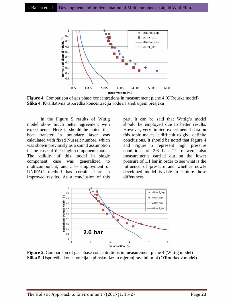
In the Figure 5 results of Wittig
model show much better agreement with
experiments. Here it should be noted that
heat transfer in boundary layer was
calculated with fixed Nusselt number, which
was shown previously as a sound assumption
in the case of the single component model.
The validity of this model in single
component case was generalized to
multicomponent, and also employment of
UNIFAC method has certain share in
improved results. As a conclusion of this
part, it can be said that Wittig’s model
should be employed due to better results.
However, very limited experimental data on
this topic makes it difficult to give definite
conclusions. It should be noted that Figure 4
and Figure 5 represent high pressure
conditions of 2.6 bar. There were also
measurements carried out on the lower
pressure of 1.1 bar in order to see what is the
influence of pressure and whether newly
developed model is able to capture those
differences.
Figure 5. Comparison of gas phase concentrations in measurement plane 4 (Wittig model)
Slika 5. Usporedba koncentracija u plinskoj fazi u mjernoj ravnini br. 4 (O'Rourkeov model)

J. Baleta et. al Development and Implementation of Multicomponent Liquid Wall Film...
The Holistic Approach to Environment 7(2017)1, 15-27 Page 24
Comparison between Figure 5 and
Figure 6 shows that lower pressure
represents smaller resistance to evaporation,
and consequently the concentrations in the
gas phase of measurement plane 4 are
higher. Since model based on the wall
functions from O’Rourke and Amsden
proved to be only qualitatively correct,
comparison with experimental data on lower
pressures was carried out only with Wittig
model. It can be seen on Figure 6 that this
model is able to capture experimental trend,
especially in the case of ethanol
concentrations. Agreement in the case of
water concentrations is not so good, but still
satisfactory, especially in the case of channel
heights closer to the film surface. Moving
away from the film surface, model under
predicts water concentrations. One of the
possible reasons for discrepancy from
experimental results even in Wittig’s model
is using lumped parameter approach where
physical quantities, such as film temperature
and liquid mass fractions, are described as
constant within film cell. Refinement of this
assumption should entail employing of some
polynomial function to better describe those
quantities or discretization of film thickness.
However, this would have negative impact
on the computational requirements.
Figure 6. Comparison of gas phase concentrations in measurement plane 4 (Wittig model)
Slika 6. Usporedba koncentracija u plinskoj fazi u mjernoj ravnini br. 4 (Wittigov model)
Finally, Figure 7 enables better
visualization of the influence of the gas
phase pressure onto the evaporation
dynamics. Great difference in the gas phase
concentrations between different pressures
can be observed. Using the same colour
legend for both cases, higher pressure shows
almost order of magnitude lower concen-
trations.
Figure 7. Influence of pressure on the gas phase concentrations - central cut
Slika 7. Utjecaj tlaka na koncentracije u plinskoj fazi – središnji presjek
J. Baleta et. al Development and Implementation of Multicomponent Liquid Wall Film...
The Holistic Approach to Environment 7(2017)1, 15-27 Page 25
CONCLUSION
This work makes improvement of the
Eulerian liquid wall film model through
further development and implementation of
numerical model of multicomponent
evaporation, with the ultimate goal of
achieving more accurate and computationally
efficient calculations as a surrogate for
experimental approaches.
Multicomponent evaporation has been
modelled by two approaches, i.e. by
employing modified wall functions derived by
physical reasoning and utilizing the analogy
between momentum and mass transfer. The
latter approach showed more accurate in terms
of comparison with experimental data from
Wittig et al. [27]. However, very limited
experimental data prevent for giving the
definitive conclusion on this matter. The
provisory nature of derived wall functions
seems to be responsible for higher
discrepancies from experiment. Particular
scientific contribution presents implemen-
tation of UNIFAC method for activity
coefficients calculation, which is employed in
the area of liquid wall films for the first time.
It enables more accurate calculation of
interface concentrations in the case of
multicomponent liquids which have a decisive
influence on the evaporation rate.
Future work should include detailed
modelling of liquid film properties, such as
temperature and concentration, by employing
some function dependency or film
discretization procedure. It should be assessed
how much would be that approach suitable by
comparing increase in accuracy versus
increase in computational time/resources.
Acknowledgement
Financial support from the European Union’s Horizon 2020 Phoenix Grant Agreement
(NUMBER -690925 –Phoenix) is gratefully acknowledged.
REFERENCES
[1] Y. Ra, R.D. Reitz, Numerical Study
of Multi-Component Spray
Combustion with a Discrete Multi-
Component Fuel Model, in: Int.
Multidimens. Engine Model. User’s
Gr. Meet. SAE Congr., Detroit, 2009:
p. 6.
[2] C.F. Lee, W.L. Cheng, D. Wang,
Finite diffusion wall film evaporation
model for engine simulations using
continuous thermodynamics, Proc.
Combust. Inst. 32 (2009) 2801–2808.
doi:10.1016/j.proci.2008.06.087.
[3] P.J. O’Rourke, A.A. Amsden, A
Particle Numerical Model for Wall
Film Dynamics in Port-Injected
Engines, 1996. doi:10.4271/961961.
[4] Y. Zeng, C. Lee, Multicomponent-
Fuel Film-Vaporization Model for
Multidimensional Computations, J.
Propuls. Power. 16 (2000) 964–973.
doi:10.2514/2.5697.
[5] D.J. Torres, P.J. O’rourke, A.A.
Amsden, Efficient multicomponent
fuel algorithm, Combust. Theory
Model. 7 (2003) 66–86.
doi:10.1088/1364-7830/7/1/304.
J. Baleta et. al Development and Implementation of Multicomponent Liquid Wall Film...
The Holistic Approach to Environment 7(2017)1, 15-27 Page 26
[6] Seyed Vahid Ebrahimian Shiadeh,
Development of multi-component
evaporation models and 3D modeling
of NOx-SCR reduction system,
Institut National Polytechnique de
Toulouse, 2011.
[7] G. Desoutter, T.P. Habchi, Chawki,
Bénédicte Cuenot, Single-component
liquid film evaporation model
development and validation using
direct numerical simulations, in: Proc.
ICLASS 2006, Kyoto, 2006: p. 8.
[8] X. Cui, X. Li, H. Sui, H. Li,
Computational fluid dynamics
simulations of direct contact heat and
mass transfer of a multicomponent
two-phase film flow in an inclined
channel at sub-atmospheric pressure,
Int. J. Heat Mass Transf. 55 (2012)
5808–5818.
doi:10.1016/j.ijheatmasstransfer.2012.
05.077.
[9] J.B. Haelssig, A.Y. Tremblay, J.
Thibault, S.G. Etemad, Direct
numerical simulation of interphase
heat and mass transfer in
multicomponent vapour–liquid flows,
Int. J. Heat Mass Transf. 53 (2010)
3947–3960.
doi:10.1016/j.ijheatmasstransfer.2010.
05.013.
[10] S. Liye, Z. Weizheng, Z. Ti’en, Q.
Zhaoju, A new approach to transient
evaporating film heating modeling
based on analytical temperature
profiles for internal combustion
engines, Int. J. Heat Mass Transf. 81
(2015) 465–469.
doi:10.1016/j.ijheatmasstransfer.2014.
10.061.
[11] Y. Yan, H. Liu, M. Jia, M. Xie, H.
Yin, A one-dimensional unsteady wall
film evaporation model, Int. J. Heat
Mass Transf. 88 (2015) 138–148.
doi:10.1016/j.ijheatmasstransfer.2015.
04.082.
[12] G. Desoutter, Etude numérique de la
propagation d’une flamme sous
l'influence d'un film liquide de
carburant sur la paroi, Institut
National Polytechnique de Toulouse,
2007.
[13] D.W. Stanton, C.J. Rutland, Multi-
dimensional modeling of thin liquid
films and spray-wall interactions
resulting from impinging sprays, Int.
J. Heat Mass Transf. 41 (1998) 3037–
3054. doi:10.1016/S0017-
9310(98)00054-4.
[14] C. Bai, A.D. Gosman, Mathematical
Modelling of Wall Films Formed by
Impinging Sprays, 1996.
doi:10.4271/960626.
[15] H. Foucart, C. Habchi, J.F. Le Coz,
T. Baritaud, Development of a Three
Dimensional Model of Wall Fuel
Liquid Film for Internal Combustion
Engines, 1998. doi:10.4271/980133.
[16] J. Ebner, P. Schober, O. Schäfer, S.
Wittig, Modelling of Shear-Driven
Liquid Wall Films on Curved
Surfaces : Effect of Accelerated Air
Flow and Variable Film Load, in:
Proc. ICLASS 2003, 9th Trienn. Int.
Conf. Liq. At. Spray Syst., Sorento,
2003.
[17] T. Lucchini, G. D’Errico, F. Brusiani,
G.M. Bianchi, Ž. Tuković, H. Jasak,
Multi-dimensional modeling of the
air/fuel mixture formation process in a
PFI engine for motorcycle
applications, in: 2009.
doi:10.4271/2009-24-0015.
J. Baleta et. al Development and Implementation of Multicomponent Liquid Wall Film...
The Holistic Approach to Environment 7(2017)1, 15-27 Page 27
[18] G. Cazzoli, C. Forte, Development of
a model for the wall film formed by
impinging spray based on a fully
explicit integration method, (2005).
doi:10.4271/2005-24-087.
[19] AVL, FIRE ® VERSION 2014.2
manual, (2015).
[20] E. Burck, Der Einfluß der Prandtl-
Zahl auf den Wärmeuübergang und
Druckverlust künstlich aufgerauhter
Strömungskanäle, Wärme-
Stoffübertrag. 2 (1969) 87–98.
[21] K.H. Sill, Wärme- und Stoffübergang
in turbulenten Strömungsgrenz-
schichten längs verdunstender
welliger Wasserfilme, Karlsruhe
Institute of Technology, 1982.
[22] C.L.V. Jayatilleke, The Influence of
Prandtl Number and Surface
Roughness on the Resistance of the
Laminar Sub-Layer to Momentum
and Heat Transfer, Prog. Heat Mass
Transf. 1 (1969).
[23] B.E. Launder, D.B. Spalding, The
numerical computation of turbulent
flows, Comput. Methods Appl. Mech.
Eng. 3 (1974) 269–289.
doi:10.1016/0045-7825(74)90029-2.
[24] A. Fredenslund, P.R. J. Gmehling,
Vapor-liquid Equilibria Using Unifac,
Elsevier, Amsterdam, 1977.
http://linkinghub.elsevier.com/retrieve
/pii/B9780444416216500016.
[25] F. Brenn, G., Deviprasath, L.J. and
Durst, Computations and Experiments
on the Evaporation of Multi-
Component Droplets, in: Proc.9th
Int.Conf.Liquid At. Syst. (ICLASS),
Sorento, 2003.
[26] S. Wittig, J. Himmelsbach, B. Noll,
H.J. Feld, W. Samenfink, Motion and
Evaporation of Shear-Driven Liquid
Films in Turbulent Gases, J. Eng. Gas
Turbines Power. 114 (1992) 395.
doi:10.1115/1.2906604.
[27] M. Gerendas, S. Wittig, Experimental
and Numerical Investigation on the
Evaporation of Shear-Driven
Multicomponent Liquid Wall Films, J.
Eng. Gas Turbines Power. 123 (2001)
580. doi:10.1115/1.1362663.
Top Related