


Languages
Pages
Legal

Deuterium-Halogen Calibration Light Source Installation and Operation Manual
For Products: DH-3-BAL-CAL, DH-3-BAL-CAL-EXT, DH-3 plus -BAL-CAL, DH-3 plus -CAL-EXT Document: 000-10000-191-02-201601

B 000-10000-191-02-201601
AMERICAS & WORLD HEADQUARTERS
Phone: +1 727-733-2447 Fax: +1 727-733-3962 Sales: [email protected] Orders: [email protected] Support: [email protected]
EUROPE, MIDDLE EAST & AFRICA
Phone: +31 26-319-0500 Fax: +31 26-319-0505 Email: [email protected] Germany : +49 711-341696-0
UK : +44 1865-811118 France : +33 442-386-588
ASIA
Phone: +86 21-6295-6600 Fax: +86 21-6295-6708 Email: [email protected]
Japan & Korea: +82 10-8514-3797
www.oceanoptics.com
Copyright © 2013 Ocean Optics, Inc. All rights reserved. No part of this publication may be reproduced, stored in a retrieval system, or transmitted, by any means, electronic, mechanical, photocopying, recording, or otherwise, without written permission from Ocean Optics, Inc.
Trademarks
All products and services herein are the trademarks, service marks, registered trademarks or registered service marks of their respective owners.
Limit of Liability Every effort has been made to make this manual as complete and as accurate as possible, but no warranty or fitness is implied. The information provided is on an “as is” basis. Ocean Optics, Inc. shall have neither liability nor responsibility to any person or entity with respect to any loss or damages arising from the information contained in this manual.
Ocean Optics, Inc. 830 Douglas Ave. Dunedin, FL 34698 USA Manufacturing & Logistics 4301 Metric Dr. Winter Park, FL 32792 USA
Ocean Optics Asia 666 Gubei Road Kirin Tower Suite 601B Changning District Shanghai PRC, 200336
Sales & Support Geograaf 24 6921 EW Duiven The Netherlands Manufacturing & Logistics Maybachstrasse 11 73760 Ostfildern Germany

000-10000-191-02-201601 A
Important Safety Notices
1. Do not remove or modify any installed safety device on this equipment. Doing so will void your
warranty and create an unsafe operating environment.
2. Dangerous voltages are present in this device. There are NO user serviceable parts inside.
3. Only allow qualified personnel to service this unit.
4. Inspect this unit and its power supply before using it for the first time. Do not use the unit if it is
damaged in any way. Contact your dealer for repair or replacement information.
5. The light source emits strong ultraviolet radiation. Wear safety glasses and UV protection
clothing.

B 000-10000-191-02-201601
000-10000-191-02-201601 i
Table of Contents
About This Manual ......................................................................................................... iii Document Purpose and Intended Audience .............................................................................. iii Document Summary .................................................................................................................. iii Product-Related Documentation ............................................................................................... iii
Upgrades ....................................................................................................................... iii
Warranty ........................................................................................................................ iv
ISO Certification ............................................................................................................ iv
Chapter 1: Setup ................................................................................ 1
Overview ....................................................................................................................... 1
Models Available ........................................................................................................... 2
Unpacking the DH-3 Series Light Source ...................................................................... 2
Contents ........................................................................................................................ 2
Connecting a Spectrometer to the DH-3 ........................................................................ 3
Chapter 2: DH-3 Specifications ......................................................... 5
Operating Environment .................................................................................................. 5 Specifications ............................................................................................................................ 5
Appendix A: Calibration Basics ........................................................ 7
Overview ....................................................................................................................... 7
Calibration for Absolute Irradiance ................................................................................. 7
Uncertainty Level Calculation for DH-3 plus-BAL-CAL ................................................... 7
Appendix B: DH-3 Use Log ............................................................... 9
DH-3 Series Use Log ..................................................................................................... 9
Index ................................................................................................... 11

Table of Contents
ii 000-10000-191-02-201601
000-10000-191-02-201601 iii
About This Manual
Document Purpose and Intended Audience
This document provides you with an installation section to get your system up and running, basic
information about the calibration light source, and a log to save the time of the light source’s use.
Document Summary
Chapter Description
Chapter 1: Setup Contains a list of package contents and unpacking instructions. Also contains procedures for connecting to a spectrometer.
Chapter 2: DH-3 Specifications Contains operating environment specifications, as well as other physical details of the product.
Appendix A: Calibration Basics Provides an overview of the physics for radiometrically calibrated systems.
Appendix B: DH-3 Use Log Provides a sample log for recording lamp use.
Product-Related Documentation
You can access documentation for Ocean Optics products by visiting our website at
http://www.oceanoptics.com. Select Support → Technical Documents, then choose the appropriate
document form the available drop-down lists.
Ocean Optics offers a Glossary of spectroscopy terms to help you further understand your state-of-the-art
products and how they function, located at: http://oceanoptics.com/glossary/.
Detailed instructions for OceanView Spectrometer Operating Software is located at:
http://oceanoptics.com/wp-content/uploads/OceanViewIO.pdf.
Upgrades Occasionally, you may find that you need Ocean Optics to make a change or an upgrade to your system.
To facilitate these changes, you must first contact Customer Support and obtain a Return Merchandise
Authorization (RMA) number. Please contact Ocean Optics Application Scientist for specific instructions
when returning a product.
About This Manual
iv 000-10000-191-02-201601
Warranty Our 3-Year Warranty covers Ocean Optics miniature fiber-optic spectrometers, spectral sensors, light
sources and sampling accessories – regardless of the application – from manufacturing defects. It also
covers fibers and probes for a full 12 months: http://oceanoptics.com/services/exclusive-3-year-
warranty/.
This comprehensive warranty ensures you of the highest level of craftsmanship and reliability for years to
come. No other manufacturer offers such a solid guarantee of quality and reliability.
The Ocean Optics 3-Year Warranty applies to Ocean Optics equipment (excluding OEM configurations)
purchased on or after July 1, 2010. The warranty covers parts and labor needed to repair manufacturing
defects that occur during the warranty period. We also will cover the costs of shipping warranty-related
repairs from our customers to Ocean Optics and from us to our customers.
ISO Certification Ocean Optics, the industry leader in miniature photonics, has been certified for ISO 9001:2008
certification applicable to the design and manufacture of electro-optical equipment since 2009.

000-10000-191-02-201601 1
Chapter 1
Setup
Overview The DH-3 Series of Halogen Calibrated Light Sources for the UV-VIS-Shortwave NIR (230nm-1100nm)
is a deuterium and halogen light source that provides known absolute intensity values at several
wavelengths, expressed in µW/cm²/nm. Since the spectral intensity of the DH-3 Series can be traced to an
intensity standard traceable to the National Institute of Standards and Technology (NIST), it is
specifically designed for calibrating the absolute spectral response of your system.
Note
If you have a spectrometer setup that is highly sensitive, you may not be able to use the
DH-3 Series as a calibration source.
DH-3 plus Calibrated Light Source
1: Setup
2 000-10000-191-02-201601
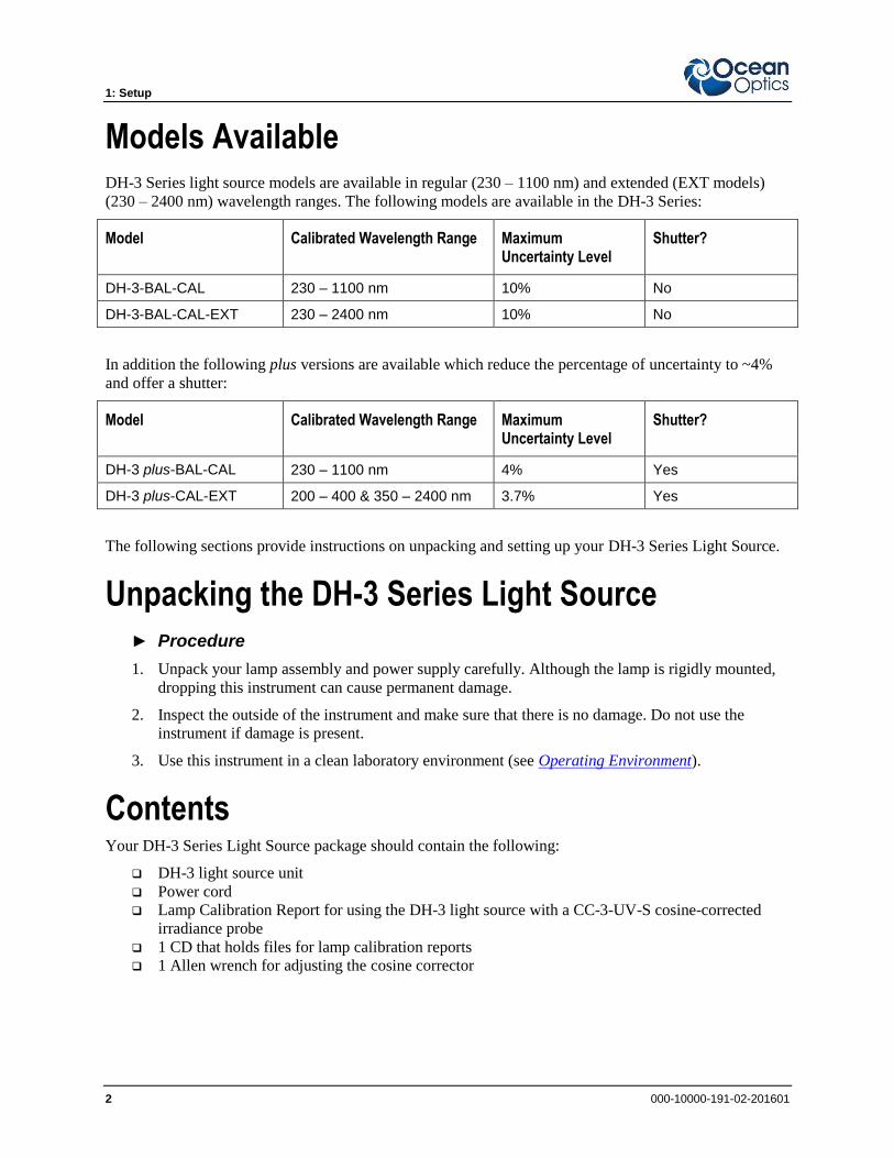
Models Available DH-3 Series light source models are available in regular (230 – 1100 nm) and extended (EXT models)
(230 – 2400 nm) wavelength ranges. The following models are available in the DH-3 Series:
Model Calibrated Wavelength Range Maximum Uncertainty Level
Shutter?
DH-3-BAL-CAL 230 – 1100 nm 10% No
DH-3-BAL-CAL-EXT 230 – 2400 nm 10% No
In addition the following plus versions are available which reduce the percentage of uncertainty to ~4%
and offer a shutter:
Model Calibrated Wavelength Range Maximum Uncertainty Level
Shutter?
DH-3 plus-BAL-CAL 230 – 1100 nm 4% Yes
DH-3 plus-CAL-EXT 200 – 400 & 350 – 2400 nm 3.7% Yes
The following sections provide instructions on unpacking and setting up your DH-3 Series Light Source.
Unpacking the DH-3 Series Light Source ► Procedure
1. Unpack your lamp assembly and power supply carefully. Although the lamp is rigidly mounted,
dropping this instrument can cause permanent damage.
2. Inspect the outside of the instrument and make sure that there is no damage. Do not use the
instrument if damage is present.
3. Use this instrument in a clean laboratory environment (see Operating Environment).
Contents Your DH-3 Series Light Source package should contain the following:
DH-3 light source unit
Power cord
Lamp Calibration Report for using the DH-3 light source with a CC-3-UV-S cosine-corrected
irradiance probe
1 CD that holds files for lamp calibration reports
1 Allen wrench for adjusting the cosine corrector
1: Setup
000-10000-191-02-201601 3
Connecting a Spectrometer to the DH-3 Before using a DH-3 Series light source for the first time, check for transport damage. Be sure to adhere
to all warnings on the unit and in this operational manual. Make sure you have your DH-3 light source,
your spectrometer, a CC-3 cosine-corrected irradiance probe, and Ocean Optics spectrometer operating
software.
► Procedure
Use the following procedure to connect your DH-3 light source to a spectrometer:
1. Loosen the set screw on the DH-3's SMA connector.
2. Screw the CC-3 cosine corrector onto the end of the fiber. The connection should be tight. Insert
the CC-3 all the way into the DH-3's SMA connector.
3. Tighten the setscrew on the SMA connector of the DH-3 with an Allen wrench. Connect the other
end of the fiber into the SMA connector of the spectrometer.
4. Plug in the power cord.
5. Turn the lamp on using the ON/OFF switch on the back of the light source.
6. Turn on the deuterium light and the halogen light on the front of the light source.
7. Allow the lamp to warm up for at least 15 minutes before using it. Place the DH-3 horizontally.
8. Insert the calibration disk that came with your light source into your computer. This disk contains
one ASCII file with the same information as the Lamp Calibration Reports that came with your
DH-3. The file name contains the lamp's serial number, followed by CC.LMP. Copy these files
to the desired directory on your computer.
9. Start your spectrometer operating software. See your spectrometer manual for instructions on
calibrating the spectrometer with the DH-3.
Tips
When you perform measurements with the calibrated spectrometer system, record a new
dark spectrum before each measurement. This minimizes the influence of a shifted dark
spectrum.
Use a log to monitor the operation time of the light source. Recalibration of the light
source after 50 hours of operation is recommended. A sample log is provided in
Appendix B: DH-3 Use Log.
1: Setup
4 000-10000-191-02-201601

000-10000-191-02-201601 5
Chapter 2
DH-3 Specifications
This section provides information on the operating environment and specifications of the DH-3 Series
light sources.
Operating Environment The following table provides information on optimizing the operating environment of your DH-3
calibration light source.
Operating Environment The DH-3 Unit . . .
Moisture Is designed for operation in dry rooms only.
Ventilation Should be placed so that its location or position does not interfere with proper ventilation.
Heat Should be placed away from any device that emits excessive heat.
Object and Liquid Entry
Should be positioned so that objects do not fall on top of the unit. Additionally, ensure that no liquids are spilled into the enclosure through openings.
Specifications
Specification Value
Spectral Range (calibrated): Regular Models EXT Models
230 – 1100 nm 230 – 2400 nm
Dimensions (LWH): DH-3-BAL-CAL and DH-3-BAL-CAL-EXT DH-3 plus-BAL-CAL and DH-3plus-CAL-EXT
13.8 cm x 6.3 cm x 6.1 cm; 5.4" x 2.5" x 2.4" 14.5 cm x 6.3 cm x 6.1 cm; 5.7" x 2.5" x 2.4"
Power Input/ Max. Power Consumption 100 W/ 190 W heating D-Lamp for 20 seconds
Time to Stabilized Output 20 minutes
Connector CC-3 cosine corrector
Shutter: Regular Models plus Models
No Yes
2: DH-3 Specifications
6 000-10000-191-02-201601
000-10000-191-02-201601 7
Appendix A
Calibration Basics
Overview Calibrated systems, independent of the particular calibrated unit, are always traceable to national
standards. A calibrated item is comparable to all calibrated items which are calibrated for the same
calibrated unit.
Each measurement result has an uncertainty, and the level of uncertainty is given either for one single
standard deviation (k = 1) or for two standard deviations (k = 2), which is often named as expanded
uncertainty.
A calibrated device should give trusted results; therefore, the calibration has to be done by the metrologist
following a previously defined and proven calibration procedure. Clear documentation of the calibration
setup and of the calibrated devices used is an indispensable requirement.
Calibration for Absolute Irradiance Absolute irradiance has the physical unit µW/nm/cm^2. The interpretation is as follows: This is the
wavelength resolved electromagnetic radiation which is emitted through an area [cm^2].
When you attach a cosine corrector correctly at the mounting of the light source then the amount of light
has a defined electromagnetic radiation power per surface area of your cosine corrector.
More detailed information can be found at: http://oceanoptics.com/frequentlyaskedquestions/light-
sources-radiometric/
Uncertainty Level Calculation for DH-3 plus-BAL-CAL Each realistic measurement has an uncertainty and therefore, a calibration has an uncertainty. The
uncertainty should be validated seriously since this reflects how reliable the calibration is. The following
international standards define the uncertainty and are describing how the uncertainty should be derived:
IEC Guide 115: Application of uncertainty of measurement to conformity assessment activities in
the electrotechnical sector.
JCGM100:2008: GUM 1995 with minor corrections
Ocean Optics calibrations are done in relation to these international standards.

A: Calibration Basics
8 000-10000-191-02-201601
Ocean Optics provides a calibration of the DH-3 plus-CAL on an absolute irradiance scale in
µW/nm/cm^2. The sources of uncertainties taken into account are listed below in the example. The actual
values are listed in the individual calibration certificate for your light source. The calibration certificate
contains more detailed information.
Sources of Uncertainties
Variable Source of uncertainty
1. R Uncertainty in reproducibility [R], caused by switching on/off
_1.1 S Stability[S] within 50 hours of operation
2. T and F
Influence of temperature [T] and humidity [F] in the air. The temperatures during calibration have a temperature range of 19 °C to 25 °C. The humidity might influence the calibration in the NIR for wavelength larger than 1100 nm.
3. d Uncertainty in mounting distance [d] of the used cosine corrector. 1.8 % per 0.1 mm deviation from aperture plane.
4. ROT Uncertainty from rotating [ROT] the cosine corrector.
5. D_Lambda
Uncertainty caused by wavelength calibration of the spectrometer which was used to calibrate the light source. [D_Lamba[QE]=0.3 nm, D_Lambda[NirQ512]= 1 nm]
6. D_AbsIrrad Uncertainty of the calibration light source used. This is in most cases the Ocean Optics working standard. See calibration certificate for details.
7. StrayL Influence from spectrometers’ internal stray light which was used to calibrate the light source.
8. T_TEC_ Influence of the sensor temperature [TEC] of the spectrometer which was used to calibrate the light source.
9. Dark Influence from uncertainties of the measured dark level of the spectrometer used to calibrate the light source.
10. Rep Reproducibility of the used spectrometer system for calibration.
11. SP_Lin Linearity of the spectrometer system which was used to calibrate the light source.
12. Bend Uncertainty caused by bending [Bend] of the fibers.
These factors are taken into account for deriving the wavelength for resolved levels of uncertainty (listed
below).
Standard Uncertainties and Uncertainty Budgets in % at Wavelength (Example)
400 500 600 800 1000 1200 1600 1800 2000 2400
Standard uncertainty k = 1 5,09 3,64 3,01 3,00 3,04 3,04 3,05 3,04 10,86 10,86
Expanded uncertainty k = 2 10,18 7,28 6,01 6,00 6,08 6,08 6,10 6,08 21,71 21,71
Place the light source horizontally. A value of 6 % of expanded uncertainty must be taken into account for
vertical placement.

000-10000-191-02-201601 9
Appendix B
DH-3 Use Log
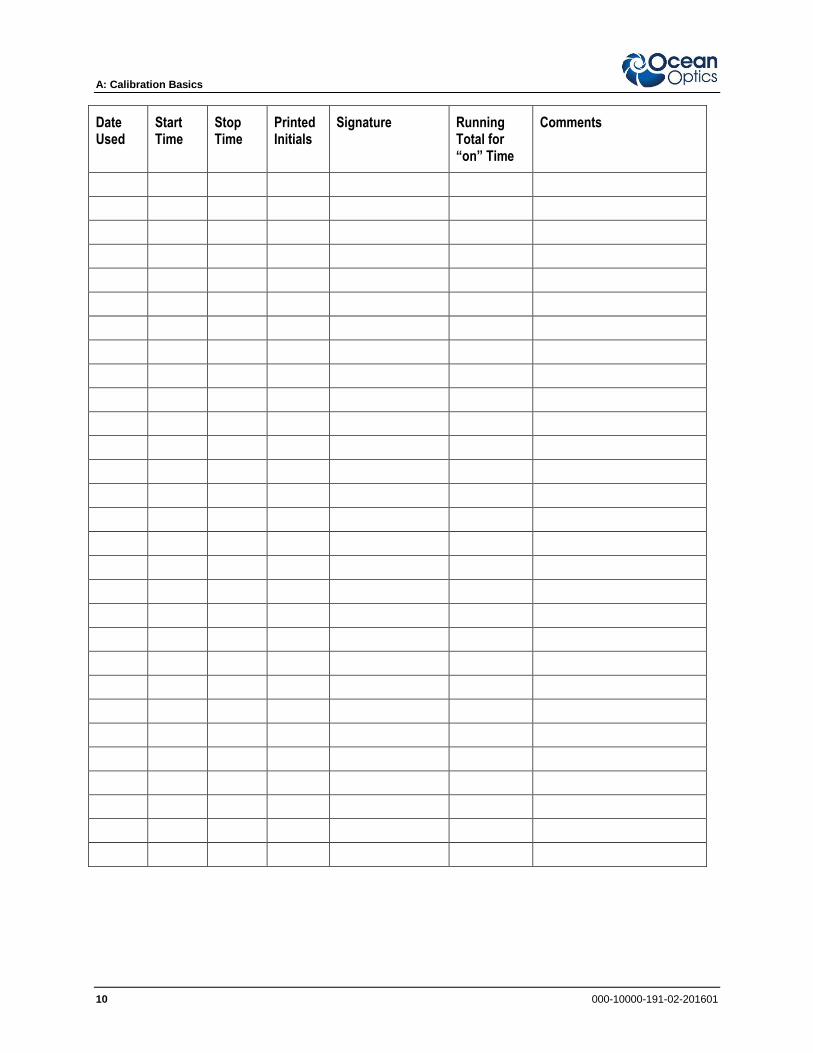
DH-3 Series Use Log
Use Log No.: Page No.: ID No.:
Lamp S/N: Date Calibrated:
Reference Standard: Working Standard:
Note: Do not exceed 50 hours of total “ON” time without recalibration.
Date Used
Start Time
Stop Time
Printed Initials
Signature Running Total for “on” Time
Comments
A: Calibration Basics
10 000-10000-191-02-201601
Date Used
Start Time
Stop Time
Printed Initials
Signature Running Total for “on” Time
Comments
000-10000-191-02-201601 11
Index
A absolute irradiance calibration, 7
C calibration, 7
connection
spectrometer, 3
D document
audience, iii
purpose, iii
summary, iii
I ISO certification, iv
L log, 9
M models, 2
O operating environment, 5
P package contents, 2
product-related documentation, iii
S safety, A
setup, 1
specifications, 5
specifications table, 5
spectrometer
connection, 3
U uncertainty level caculation, 7 unpacking, 2
upgrades, iii
W warranty, iv

Index
12 000-10000-191-02-201601
Top Related