


Languages
Pages
Legal


Design, Fabrication and Testing of Magnetic
Composite Polymer Actuators Integrated With
Microfluidic Devices and Systems
by
Mona Rahbar
M.A.Sc., Simon Fraser University, 2010 B.Eng. Azad University of Qazvin 2004
Thesis Submitted in Partial Fulfillment of the
Requirements for the Degree of
Doctor of Philosophy
in the
School of Engineering Science
Faculty of Applied Sciences
Mona Rahbar 2016
SIMON FRASER UNIVERSITY
Fall 2016
ii
Approval
Name: Mona Rahbar
Degree: Doctor of Philosophy
Title: Design, Fabrication and Testing of Magnetic Composite Polymer Actuators Integrated with Microfluidic Devices and Systems
Examining Committee: Chair: Michael Sjoerdsma Senior Lecturer
Bonnie Gray Senior Supervisor Professor
Carlo Menon Supervisor Associate Professor
Andrew Rawicz Internal Examiner Professor School of Engineering Science
Boris Stoeber External Examiner Professor Department of Mechanical Engineering University of British Columbia
Date Defended/Approved: September 27, 2016

iii
Abstract
Work presented in this thesis demonstrates methods of combining a newly
developed magnetic composite polymer (M-CP) with other commonly used polymer
microfluidics materials for the creation of complex all-polymer microfluidic systems. To
achieve fully integrated microfluidic systems, new fabrication techniques for integration
of M-CP structures are developed. Employing the new M-CP material and the novel
fabrication techniques, three types of actuators are developed: cilia, flap, and hybrid M-
CP/PDMS actuator. All three actuators employ compatible materials, fabrication
techniques, and actuation mechanisms. The performance of each of these actuators is
characterized for different applications: cilia-based mixers, flap-based valves, and hybrid
M-CP/PDMS actuators for applying extracellular stimulation on cell monolayers. The
actuators in each of these applications are driven via relatively small external magnetic
fields. The M-CP used in these novel actuators is composed of rare-earth magnetic micro-
particles (5–10 micrometer) that are embedded in polydimethylsiloxane. The M-CP is
patterned into large force, large stroke actuators. The polymer matrix without magnetic
particles is employed as the substrate material for passive parts, facilitating integration of
the magnetic and non-magnetic materials. The compatible fabrication techniques include
a modified soft-lithography technique for hybrid M-CP/PDMS actuators, screen printing
via shadow masks for micro-patterning of thin layers of M-CP, and a novel fabrication
technique using poly(ethylene glycol) (PEG) as a sacrificial material for the fabrication of
ultra-high aspect-ratio and highly flexible M-CP cilia. Microfluidic devices using these
actuators show improved performances in their respective fields when compared with
existing designs. Microfluidic mixers with 8 cilia show a reduction in mixing time of up
to 63 times over diffusion. Flap-based valve arrays effectively switch flows between two
microfluidic channels using an array of two valves, and effectively perform as on-off
switches for flow control. A valve with a 2.3 mm flap thickness, actuated under an 80 mT
magnetic field, is capable of blocking liquid flow at a flow rate of 1 mL/min for pressures
up to 9.65 kPa. Microfluidic platforms for stretching/compressing biological cells based
on the hybrid M-CP/PDMS actuators achieve large and bi-directional surface deflections.
Actuation can be applied cyclically, under both flow and no-flow conditions.

iv
Keywords: Magnetic microfluidic actuators; magnetic composite polymer; all-polymer microfluidic systems; rare-earth magnetic powder; hard-magnetic materials

v
Dedication
This thesis is dedicated to my best friend, biggest
support and husband, Nicholas C. Doyle, without whom
I would be lost in life. Thank you for always being there
for me.

vi
Acknowledgements
I would like to offer my sincere appreciation to my supervisor Dr. B. Gray for her
incredible guidance and support. Her patience and support has made this work possible.
Additional thanks to my thesis committee members Dr. B. Stoeber, Dr. A. Rawicz and
Dr. C. Menon for their contributions. Warm thanks go to Michael Sjoerdsma for chairing
my defense.
I would like to thank the members of Micro-Instrumentation Laboratory and
Reconfigurable Computing Laboratory with whom I had the pleasure to collaborate. I
was delighted to interact with all my colleagues in the lab because of whom my graduate
experience has been one that I will cherish forever.
I like to extend my deepest gratitude to my husband Nicholas Doyle for all his
supports, encouragements, and help every single step throughout my graduate studies.
My greatest thank goes to my parents, Fakhri and Ali, and my brothers Eric Bright and
Alireza Rahbar. They have been a constant source of love, support and strength
throughout my life.
Finally, I also thank the Canadian National Engineering and Science Research
Council (NSERC), CMC Microsystems, the Canadian Foundation for Innovation, and
Magnequech International for supplying software, equipment, and magnetic powders that
made this research possible.
vii
Table of Contents
Approval ............................................................................................................................ ii
Abstract ............................................................................................................................. iii
Dedication .......................................................................................................................... v
Acknowledgements .......................................................................................................... vi
Table of Contents ............................................................................................................ vii
List of Figures ................................................................................................................... xi
List of Tables ................................................................................................................... xx
List of Abbreviations .................................................................................................... xxii
Chapter 1 - Introduction .................................................................................................. 1
1.1 Thesis Motivation ............................................................................................... 3
1.2 Thesis Contributions and Objectives .................................................................. 7
1.3 Outline of Thesis ................................................................................................. 8
Chapter 2 - Background ................................................................................................. 10
2.1 Microfluidics ..................................................................................................... 10
2.2 Integrated Microfluidic Actuation .................................................................... 12
2.2.1 Electrostatic Actuation .................................................................................. 13
2.2.2 Piezoelectric Actuation ................................................................................. 13
2.2.3 Pneumatic Actuation ..................................................................................... 14
viii
2.2.4 Thermal Actuation ........................................................................................ 15
2.2.4.1 Thermo-pneumatic Actuation ............................................................... 15
2.2.4.2 Shape Memory Alloy Actuation ........................................................... 15
2.2.4.3 Solid-expansion Actuation .................................................................... 16
2.2.4.4 Bimetallic Actuation ............................................................................. 16
2.2.5 Electromagnetic and Magnetic Actuation .................................................... 17
2.3 Advantages of the Magnetic Actuation Technique Used in This Thesis over
Other Techniques .......................................................................................................... 18
Chapter 3 - Magnetic Composite Polymers for Microfluidic Devices and Systems . 21
3.1 Polymeric Materials for Composite Polymers .................................................. 21
3.2 Magnetic Materials ........................................................................................... 25
3.2.1 Background ................................................................................................... 26
3.3 Magnetic Composite Polymer ........................................................................... 31
3.3.1 Material Characterization ............................................................................ 34
3.4 Chapter Summary and Conclusions .................................................................. 45
3.5 Related Publications .......................................................................................... 45
Chapter 4 - Ultra-high Aspect-ratio Bio-inspired Artificial Cilia Actuator .............. 46
4.1 Artificial Cilia Design and Fabrication ............................................................. 48
4.2 Artificial Cilia Actuator Application: Microfluidic Cilia Mixer ...................... 65
4.2.1 Background ................................................................................................... 67
4.2.2 Experimental Setup ....................................................................................... 69
4.2.3 Experimental results ..................................................................................... 74
4.3 Comparison with the Prior Art .......................................................................... 82

ix
4.1 Summary and Conclusion ................................................................................. 90
4.2 Related Publications .......................................................................................... 92
Chapter 5 - Flap-based Magnetic Composite Polymer Actuator ............................... 93
5.1 Flap-based Actuator Design and Fabrication .................................................... 94
5.2 Flap-based Magnetic Composite Polymer Actuator Application: All-polymer
Microfluidic Valve ...................................................................................................... 100
5.2.1 Introduction ................................................................................................. 100
5.2.2 Material ....................................................................................................... 102
5.2.3 Valve’s Design and Fabrication ................................................................. 103
5.2.4 Valve’s Fabrication Process ....................................................................... 105
5.2.5 Experimentation Results and Discussion .................................................... 108
5.2.5.1 Performance Characterization of a Single Valve as an On/Off Valve 109
5.2.5.2 Operation of Multiple Valves for Flow Switching ............................. 115
5.2.5.3 Actuation Mechanism ......................................................................... 117
5.2.6 Comparison with the Prior Art ................................................................... 124
5.3 Summary and Conclusion ............................................................................... 127
5.4 Related Publications ........................................................................................ 129
Chapter 6 - Hybrid M-CP/PDMS Actuators for Large and Bi-directional Surface
Deflections ...................................................................................................................... 130
6.1 Hybrid M-CP/PDMS Actuators for Increased Actuator Compliancy and
Actuation Range .......................................................................................................... 132
6.2 Hybrid M-CP/DPMS Actuator Application: Cell Stimulation Platform ........ 138
6.2.1 Design and Fabrication .............................................................................. 141
6.2.2 Experimental Setup ..................................................................................... 145

x
6.3 Experimental Results ...................................................................................... 149
6.4 Summary and Conclusion ............................................................................... 151
6.5 Related Publications ........................................................................................ 151
Chapter 7 - Summary of Thesis Contributions .......................................................... 152
7.1 Material Development .................................................................................... 153
7.2 Technology Development ............................................................................... 155
7.3 Application Outcome: Development and Performance Characterization of Key
Rare-earth All-Polymer Actuators .............................................................................. 156
7.4 List of Publications ......................................................................................... 157
Chapter 8 - Conclusion and Future Work .................................................................. 159
References ...................................................................................................................... 162

xi
List of Figures
Figure 1: Conceptual drawing of multifunctional microfluidic platform employing the
technologies and devices developed in this thesis (this graph is reprinted with
permission from Strategic Grant 396755-10, “An on-site, reconfigurable, multi-
sample microfluidic-platform for rapid parallel sample-manipulation”, B.L. Gray
(PI) and L. Shannon). .................................................................................................. 6
Figure 2: Schematic of domains in ferromagnetic material (top) before, and (bottom) after
magnetization. ........................................................................................................... 26
Figure 3: Magnetic flux density (B) versus magnetic field strength (H) hysteresis curve of
ferromagnetic materials. ........................................................................................... 27
Figure 4: The magnetization, M, versus magnetic field strength, H, hysteresis curve of
ferromagnetic materials. ........................................................................................... 28
Figure 5: B-H hysteresis loop of (a) hard- and (b) soft-magnetic materials. .................... 29
Figure 6: Instron MicroTester used for tensile strength test. ............................................ 35
Figure 7: This photo shows the shape and dimensions of two of the M-CP samples used
for tensile strength testing. The samples’ thicknesses are 1 ± 0.1 mm. Sample doping
level ranged from 0 to 80 wt-% in 10 wt-% increments. The two wider ends are used
to clamp the samples to the Instron MicroTester machine. ...................................... 36
Figure 8: A typical stress-strain curved produced by Instron MicroTester for 80% doped
M-CP. ........................................................................................................................ 37
Figure 9: Young’s modulus versus doping percentage of particles in M-CP using samples
as illustrated in Figure 7. Horizontal error bars represent ± 1% accuracy in PDMS
doping level and vertical error bars represent one standard deviation over 9 samples
at each doping level. This image is adapted from [109]. .......................................... 39
Figure 10: Illustration of the samples used to measure magnetic attraction/repulsion
forces between M-CP samples (with different thicknesses) and an 80 mT external
magnetic field............................................................................................................ 40
Figure 11: Relationship between M-CP sample thickness and the attraction/repulsion
force exerted on each permanently magnetized M-CP sample doped at 80 wt-% and
actuated under an 80 mT external magnetic field. The horizontal error bars represent
± 0.01 mm accuracy for thickness and the vertical error bars represent one standard
deviation over 5 measurements at each point. Horizontal error bars present ± 0.025
µm variation in the sample thicknesses. ................................................................... 41
Figure 12: Illustration of a cylindrical permanently magnetized M-CP with a radius of R,
and height of D.......................................................................................................... 42
Figure 13: Normalized relationship between the force between the two magnetized
surfaces and magnet thickness. ................................................................................. 43

xii
Figure 14: Schematic of the setup used to measure the magnetic field created by each M-
CP sample with different thicknesses at different gaps (distance between the sample
and Gauss/Tesla meter). ............................................................................................ 44
Figure 15: Magnetic field produced by samples of permanently magnetized M-CP (doped
at 80 wt-%, and of different thicknesses) in the absence of any external magnetic
field. Gap size is defined as the distance between the top surface of the M-CP
sample and the tip of the Hall Effect sensor (see Figure 14). M-CP cross-sectional
dimensions are 2 2 mm2, with different thicknesses as shown in the legend. ....... 44
Figure 16: Artificial cilia fabricated directly inside (a) a microfluidic reaction chamber,
and (b) a microfluidic channel. ................................................................................. 49
Figure 17: Schematic of a sample microfluidic reaction chamber used for performance
characterization tests on the microfluidic mixers based on artificial cilia actuators. 49
Figure 18: Steps of the micro-fabrication process for M-CP cilia. (a) Molding of PDMS.
(b) Demolding of PDMS. (c) Filling chamber with PEG (Mn = 2050). (d) Removing
excess PEG from the surface. (e) Covering with aluminum layer. (f) Inserting micro-
needle. (g) Pouring M-CP. (h) Removing micro-needle. (i) Removing excess M-CP
from the surface. (j) Curing. (k) Removing the aluminum layer. (l) Dissolving the
PEG and releasing the cilia. (m) Drying under a magnetic field. ............................. 51
Figure 19: Residual layer of M-CP at the base of a cilium. This residual layer is caused
by small cracks that occasionally occur while inserting the micro-needle (cilia
diameter = 130 ± 5 µm, cilia height = 1 mm). .......................................................... 52
Figure 20: Cilium mixer fabricated by following the extra steps of heating and re-flowing
of the PEG sacrificial mold after the insertion of micro-needles. The re-heating and
cooling steps ensure that there is no crack or gap between the PEG and the
underlying PDMS layer, (cilia diameter = 130 ± 5 µm, cilia height = 1.2 mm). ..... 53
Figure 21: A conceptual illustration of micro-needle stamps that could potentially be used
in artificial cilia fabrication. ...................................................................................... 53
Figure 22: Custom made permanent magnet by Dexter Magnetic Technologies used to
magnetize M-CP, (Magnetic field = 1.8 ± 0.2 T). .................................................... 54
Figure 23: Schematic of microfluidic systems used for leakage tests: mixer/reaction
chambers with single cilium actuator fabricated directly inside the chamber. (a) top
layer, (b) bottom layer, (c) top and bottom layer assembled together and bonded
using plasma activation, and (d) cross-sectional view of the final microfluidic
device. ....................................................................................................................... 56
Figure 24: Ultra-high aspect-ratio cilium in the absence of an external magnetic field
(cilium length = 8 ± 0.1 mm, cilium diameter = 130 ± 5 μm. Aspect-ratio = 8:0.13 =
61.54). ....................................................................................................................... 57
Figure 25: Illustration of a reaction chamber used for the characterization tests presented
in this work. Reaction chamber height is (HRC) = 1.7 ± 0.5 mm and reaction chamber
diameter is (DRC) = 4 ± 0.5 mm. ............................................................................... 58

xiii
Figure 26: Cilia structures in their full range of motion actuated using a small (110 mT)
permanent magnet. The cilia have diameter of 130 ± 5 μm and length of 2 ± 0.01
mm. In the absence of the external magnetic field, these cilia structures stand upright
similar to the cilia structure shown in Figure 27....................................................... 59
Figure 27: High aspect-ratio cilium free-standing microstructure (cilium structure
standing vertically in the absence of an external magnetic field, cilium length = 2.8 ±
0.01 mm, cilium diameter = 130 ± 5 μm, aspect-ratio of 2.8:0.13 = 21.54). ............ 59
Figure 28: Ultra-high aspect-ratio cilium structure in the absence of an external magnetic
field. (Cilium length = 5 mm, and cilium diameter = 130 ± 5 μm). Although such
structures can be realized, they are not able to stand upright freely in the absence of
an external magnetic field and are not employed as microfluidic mixer elements for
this reason and due to the size of the mixer chamber. .............................................. 60
Figure 29: Cilia structures with different diameters fabricated in reaction chambers. (Left)
Cilium diameter = 830 ± 5 µm, (right) cilium diameter = 130 ± 5 µm. ................... 61
Figure 30: Cilium structure actuated using a 7 mT magnetic field at 60 Hz provided by a
miniature electromagnet (cilium height = 2 ± 0.5 mm and cilium diameter = 130 ± 5
µm). ........................................................................................................................... 61
Figure 31: Cilia actuators with different heights fabricated on the same PDMS substrate
(cilia diameter for all cilia actuators = 130 ± 5 µm. Cilium height from left to right:
0.5 ± 0.1 mm, 1 ± 0.1 mm, 1.8 ± 0.1 mm, and 2 ± 0.1 mm). .................................... 62
Figure 32: An array consisting of four cilia actuators with different sizes actuated using a
7 mT electromagnet at 60 Hz (cilium diameter = 130 ± 5 μm for all four cilia). This
image demonstrates the control over cilia height and placement which is possible
with the new fabrication method, and shows that cilia of different heights have
different ranges of vibrational motion under the 7 mT, 60 Hz magnetic field. ........ 62
Figure 33: Artificial cilia structures fabricated directly inside (a) a microfluidic reaction
chamber, and (b) a microfluidic channel. There is no need to additional assembly as
is required in other cilia fabrication processes [106,121]. ........................................ 63
Figure 34: A 2 × 3 array of six cilia (cilia diameter = 130 ± 5 μm, cilia height = 1.5 mm,
and gap between the cilia = 1 ± 0.1 mm). ................................................................. 63
Figure 35: Cilia structures fabricated on the same reaction chamber. Each of the cilia
structures has a different angle with respect to the vertical line (Cilia diameter = 130
± 5 μm, and cilia height = 1 mm). ............................................................................. 64
Figure 36: An array of three cilia with different ratio of doped to un-doped PDMS
sections along the cilia lengths: 0% of the length is doped M-CP on the left, 40% of
the length doped in the middle, and 100% of the length doped on the right, (doping
level at 80 wt-% magnetic particles in the PDMS matrix for the doped sections). .. 65
Figure 37: (Left) an array of three cilia with different ratio of doped to un-doped PDMS
sections along the cilia lengths: 0% of the length is doped M-CP on the left, 40% of
the length doped in the middle, and 100% of the length doped on the right, (doping
level at 80 wt-% magnetic particles in the PDMS matrix for the doped sections).
(Right) the same cilia structures actuated in a 110 mT magnetic field, showing the

xiv
different range of tip displacement from 0 º for un-doped cilia to 90 º for 100%
magnetic cilia. ........................................................................................................... 65
Figure 38: Testing reaction chamber used to capture cilia mixer performance. (The
reaction chamber has a diameter = 4 ± 0.5 mm, and a height = 1.7 ± 0.5 mm. Cilium
diameter = 130 ± 5 µm, and cilium height = 1.5 ± 0.01 mm). .................................. 69
Figure 39: Miniature electromagnet used for cilia actuation (outer cylinder: diameter =
9.6 mm, height = 16.7 mm). ..................................................................................... 70
Figure 40: Cilium structure range of motion, R, actuated using a 7 mT miniature
electromagnet at 60 Hz (cilium diameter = 130 ± 5 µm, cilium length = 2 mm). .... 70
Figure 41: A cilium located on top of a miniature electromagnet and actuated using a 7
mT magnetic field at 60 Hz. This cilium is fabricated on a flat piece of PDMS
(cilium diameter = 130 ± 5 µm, cilium length = 1.5 mm). ....................................... 71
Figure 42: Illustration of the cross-sectional view of the configuration of a mixing
chamber and electromagnet employed for testing. This diagram is for illustration
purpose and is not to scale. ....................................................................................... 71
Figure 43: Experimental setup used for the characterization tests. .................................. 72
Figure 44: Illustration of the experimental setup used for the characterization tests. ...... 72
Figure 45: Reaction chamber illuminated from top with strong light reflection from the
top surface of the blue liquid inside the reaction chamber, which interferes with the
accuracy of the image processing step. ..................................................................... 73
Figure 46: Reaction chamber illuminated from bottom as shown in Figure 43 with no
light reflection from the top surface of the liquid. .................................................... 73
Figure 47: Single color dye mixed with DI-water. It does not provide enough color
change between un-mixed, initial stage, and mixed, final stage, for accurate image
analysis. ..................................................................................................................... 74
Figure 48: Multiple color dyes mixed with DI-water. This technique is used for mixer
performance characterization testing. It provides enough clear color change between
un-mixed, initial stage, and mixed, final stage, for accurate image analysis. ........... 74
Figure 49: Range of motion for an array of three cilia actuated in 7 mT magnetic field
before magnetization (left) and after magnetization (right) in 1.8 ± 0.2 T magnetic
field (cilium diameter = 130 ± 5 µm, cilium = 2 ± 0.01 mm, magnetization field =
1.8 ± 0.2 T, actuation field = 7 mT). ......................................................................... 75
Figure 50: Relationship between the cilium length, applied magnetic field and cilium tip
displacement (Cilium diameter = 130 ± 5 µm. Actuation frequency = 60 Hz. All the
displacement values have measurement accuracy of ± 2 µm). This graph is reprinted
with permission from [111]. ..................................................................................... 77
Figure 51: Experimental cilium mixing results showing percentage mixed over elapsed
time for different actuation frequencies at 7 mT. 0 Hz is no actuation (diffusion
only) (cilium length = 1.5 ± 0.01 mm, cilium diameter = 130 ± 5 µm). This graph is
reprinted with permission from [111]. ...................................................................... 78

xv
Figure 52: Sample images of the mixing process compared to diffusion alone. (a) and (b)
show 60 Hz actuation of the cilium at times t = 0 min and t = 15 min, respectively.
(c) and (d) show natural diffusion at times t = 0 min and t = 15 min, respectively,
with no cilium actuation. This image is reprinted with permission from [111]. ...... 79
Figure 53: Experimental cilium mixing results showing percentage mixed over elapsed
time for different applied excitation electromagnetic fields (cilium length = 1.5 ±
0.01 mm, and cilium diameter = 130 ± 5 µm). This graph is reprinted with
permission from [111]............................................................................................... 80
Figure 54: Cilia arrangement in the mixing chamber for multiple cilia mixers. The
illustrations on the right side are from a viewpoint looking down into the chamber
and showing the placement of the multiple free-standing vertical cilia. The distance
between each two adjacent cilium is approximately 1mm. This diagram is for
illustration purpose and is not to scale. ..................................................................... 81
Figure 55: Mixer performance for different number of cilia microstructures per chamber
after one minute of mixing at 60 Hz and applied magnetic field of 7 mT. This graph
is reprinted with permission from [111]. .................................................................. 82
Figure 56: Cross-section of a microfluidic channel created using Universal Laser
System’s VersalLASER©
Laser ablation system CO2 laser. This image is reprinted
with permission from [111]. ..................................................................................... 84
Figure 57: Cilia structures fabricated from the same material using two different
techniques. (a) Using a mold made by patterning commercial poly(methyl
methacrylate), PMMA, using a CO2 laser cutter (height = 2 ± 0.5 mm), similarly to
[9] except employing highly magnetic rare-earth materials and (b) using the new
fabrication technique described in this work (height = 1.8 ± 0.01 mm). Both of these
structures are actuated using a 110 mT permanent magnet, showing higher flexibility
for cilia fabricated using the new fabrication technique presented in this thesis. This
image is reprinted with permission from [111]......................................................... 84
Figure 58: (a) M-CP cilia structure and actuation mechanism fabricated in this thesis. (b)
Fe-doped cilia structure and actuation mechanism suggested by Riahi et al. [19], and
(c) Fe-doped cilia structure and actuation mechanism suggested by Liu et al. [106].
Both of the rotating magnet used by Riahi et al. and the moving magnet used by Liu
et al. need to be orders of magnitude stronger than the electromagnet used in this
thesis due to the use of weakly magnetic Fe-doped polymers. The doping level of Fe
powder in PDMS used by Liu et al. is limited to a maximum of 40% w/w as
opposed to 80% rare-earth magnetic powder in PDMS used in this thesis. The cone
shape of the structure proposed by Riahi et al. significantly reduces the flexibility of
the cilia structure. Both of the structures suggested by Riahi et al. and Liu et al. are
not capable of providing bi-directional actuation since Fe doped polymers are only
capable of providing attraction force. As a result the achievable vibration range in
both cases is at most half of that of the cilia structure suggested in this thesis. ....... 86
Figure 59: Cross-sectional view of the cilia structure reported in [116]. This image is
reprinted with permission from [111]. ...................................................................... 88
Figure 60: A beam structure actuated under a uniformly distributed load of W. .............. 94

xvi
Figure 61: Normalized and simplified graph that shows the relationship between the
thickness of the M-CP material, D, and its magnetic flux density, B. ...................... 96
Figure 62: Photograph of a step-shaped circular M-CP flap used for the valve fabrication
in this chapter. ........................................................................................................... 97
Figure 63: Comparison between the maximum deflections achievable by 2 mm thick
rectangular flaps: (a) shows a flat flap before applying the external actuation field,
and (c) shows the flat flap actuated under an 80 mT external magnetic field; (b)
shows a step-shaped flap before applying the external actuation field, and (d) shows
the step-shaped flap actuated under an 80 mT external magnetic field. ................... 97
Figure 64: Comparison between the maximum deflections achievable by (a) a 1 mm thick
flat-flap actuated under 80 mT external magnetic field; and (b) a 1 mm thick step-
shaped flap (similar to the design used in the valve’s fabrication) actuated under 80
mT external magnetic field. Diameter of the M-CP flaps = 6 mm. This image is
reprinted with permission from [126]. ...................................................................... 99
Figure 65: Fabrication process for the step-shaped flap actuators. (a) fabrication of
PMMA mold using a Universal Laser System’s VersalLASER©
CO2 Laser ablation
system, (b) pouring M-CP, (c) removing excess M-CP from the surface, (d) curing
M-CP at 80 °C for 2 hours, (e) de-molding of M-CP valve flap (6 mm in diameter).
................................................................................................................................... 99
Figure 66: (a) Top view of a microfluidic system with a single valve structure, (b) cross-
sectional view of the function of a single valve in open valve position, (c) cross-
sectional view of the function of a single valve in closed valve position (the
permanent magnet is employed to actuate the valve flap), (d) a valve flap fabricated
in M-CP (6 mm in diameter), (e) a valve chamber fabricated in PDMS, (f) a hybrid
microfluidic channel system, which includes passive microfluidic channels
fabricated in PDMS and a valve seat fabricated from M-CP. These diagrams are for
illustration purpose and do not represent exact dimensional ratios. This image is
reprinted with permission from [126]. .................................................................... 104
Figure 67: (a) Top view of a microfluidic channel system with printed M-CP valve seats
(two valves are shown in a flow switching configuration), (b) photographs of the
microfluidic channel system with printed valve seats (thickness of the valve seats =
200 µm, diameter of the valve seats = 6 mm), (c) photograph of a single M-CP
valve flap (diameter of the valve flap = 6 mm), (d) photograph of an assembled
device with the flaps and valve chambers mounted on the valve seats. This image is
reprinted with permission from [126]. .................................................................... 105
Figure 68: Fabrication process of the microfluidic channel systems and M-CP valve seat.
(a) patterning of PMMA mold using a Universal Laser System’s VersalLASER©
CO2 laser ablation system, or SU-8 mold using standard soft lithography techniques,
(b) molding of PDMS microfluidic channel system, (c) de-molding of PDMS, (d-h)
patterning of the valve seat, a thin (200 µm) layer of M-CP on top of the
microfluidic channel system using shadow mask screen printing, (i) punching
inlet/outlet holes using a 21 gauge dispensing needle, (j) bonding the PDMS

xvii
channels to a glass slide substrate using plasma surface activation technique. This
image is reprinted with permission from [126]....................................................... 107
Figure 69: Test setup used for the evaluation of valve performance. ............................. 108
Figure 70: Schematic of the microfluidic device used for determining a single valve’s
burst pressure in its closed position. This image is reprinted with permission from
[126]. ....................................................................................................................... 110
Figure 71: Results of the burst pressure measurements performed on valves with different
flap thicknesses actuated under an 80 mT magnetic field. Five valves are used for
each flap thickness. Accuracy for the flap thickness measurements is ± 0.1 mm.
Vertical error bars represent one standard deviation over 5 valves at each flap
thickness. This image is reprinted with permission from [126]. ............................. 112
Figure 72: Calculated attraction/repulsion forces produced by M-CP samples with
different thicknesses actuated under an 80 mT external magnetic field obtained by
dividing the data shown in Figure 11 for the force measurement by the surface area
of the M-CP samples. .............................................................................................. 113
Figure 73: Diagram of geometry used for the approximation of dead volume in a valve
structure with a flap thickness of 1 mm and a gap size of 0.5 mm on top of the flap.
This image is reprinted with permission from [126]. ............................................. 115
Figure 74: Microfluidic channel system designed to test the performance of the valves in
an array for flow switching between two branches in a Y-shaped microfluidic
channel system. This image is reprinted with permission from [126]. ................... 117
Figure 75: Diagram of the microfluidic system used to test the valve’s actuation
mechanism. (a) top-down view, (b) cross-sectional view of the valve chamber with
the actuation mechanism for providing the external magnetic force to the valve. This
diagram includes the miniature linear motor and permanent magnet located under
the valve chamber. This diagram is for illustration purpose and does not represent
exact dimensional ratios. ......................................................................................... 118
Figure 76: Miniature Linear Motion Series PQ12 from Firgelli Technologies Inc. used to
move an external magnetic field, as provided by a small permanent magnet, to
actuate different valves in the microfluidic system. ............................................... 119
Figure 77: Schematic of the complete microfluidic system with both active opening and
active closing states using permanent magnets of opposite polarity for opening and
closing. This diagram is for illustration purpose and does not represent exact
dimensional ratios. This image is reprinted with permission from [126]. .............. 120
Figure 78: Illustration of the setup used to determine the most effective direction for
moving the magnet as determined by the sharpest transition from closed valve
position to open valve position. The axes indicate the direction along which the
permanent magnet is moved. This image is reprinted with permission from [126].
................................................................................................................................. 121
Figure 79: Effect of the different directions in which the permanent magnet is moved
under the valve on the valve’s performance when switched between open and closed
valve positions. These results indicate that moving the permanent magnet in the “-

xviii
X” direction provides the sharpest transition from closed valve position to open
valve position. This image is reprinted with permission from [126]. ..................... 122
Figure 80: This simplified schematic illustrates the interaction between the magnetic field
(illustrated as magnetic field lines) of the permanent magnet and the valve flap as
the external magnet field is moved away from the valve’s center. This image is
adapted with permission from [126]. ...................................................................... 123
Figure 81: Process steps of micro-patterning of M-CP actuators on the top surface of a
thin PDMS substrate. (a) Patterning PMMA mold using a CO2 Universal Laser
System’s VersaLASER©
laser ablation system. (b) Pouring M-CP. (c) Removing
excess M-CP from the surface. (d) Pouring PDMS and curing. (e) Demolding. ... 132
Figure 82: Photograph of M-CP structures patterned on top of a 500 µm PDMS substrate
using the process steps shown in Figure 81. ........................................................... 133
Figure 83: Illustration of the actuators used for testing the effect of M-CP doping of the
base plate on the actuation range for two actuator types: (a) M-CP actuator with an
M-CP base plate and (b) hybrid M-CP/PDMS actuator with an un-doped PDMS
base plate. Actuation magnetic field = 300 mT. This diagram is for illustration
purpose and does not represent exact dimensional ratios. ...................................... 134
Figure 84 : Actuation range for hybrid M-CP/PDMS actuators (Figure 83(a)) and M-CP
actuators (Figure 83(b)) at different base thicknesses. Width of the base plate = 1
mm for all tested actuators. Vertical error bars represent one standard deviation over
3 samples at each thickness..................................................................................... 135
Figure 85: An M-CP surface supported along three edges and free on the forth edge. .. 136
Figure 86: Design of the test structure used to characterize the relationship between the
hybrid M-CP/PDMS actuator’s width and actuation range. This diagram is for
illustration purpose and is not to scale. ................................................................... 137
Figure 87: Relationship between the actuator’s width and the actuator’s maximum
deflection in a 300 mT magnetic field (thickness = 150 µm). This graph is adapted
with permission from [109]. ................................................................................... 138
Figure 88: Fabrication process using the SU-8 molds: (a) SU-8 micro-mold is fabricated
following standard SU-8 fabrication techniques; (b) PDMS is molded, cured, and
de-molded; (c) M-CP is filled where actuators will be located, and the excess M-CP
is removed; device is cured at 80 °C for 2 hours and placed in a 1.8 ± 0.2 Tesla
external magnetic field after curing for permanent magnetization; (e) PDMS lid is
bonded to the chip using corona surface activation technique. .............................. 142
Figure 89: (a) schematic and (b) photograph of the device fabricated using SU-8 mold.
................................................................................................................................. 142
Figure 90: Fabrication process using the PMMA molds: (a) PMMA micro-mold is
fabricated using multi-step laser ablation to achieve multi-level mold; (b) M-CP is
applied where actuators will be; (c) excess M-CP is scraped off, and M-CP is cured;
(d) PDMS is molded; (e) PDMS is cured, and de-mold; device is placed in a 1.8 ±
0.2 Tesla external magnetic field after curing for permanent magnetization; (f)
PDMS lid is bonded to the chip using corona surface activation technique. .......... 143

xix
Figure 91: (a) schematic and (b) photograph of the device fabricated using PMMA multi-
level mold and modified soft-lithography technique. ............................................. 143
Figure 92: Illustration of (a) and (b) ideal case for attaching the lid to the microfluidic
base, and (c) and (d) a small gap, up to approximately 70 µm, that may exist
between the lid and the base due to either (c) an overfilled M-CP reservoir in case of
the devices made using SU-8 molds, or (d) difficulty in manually aligning and
sealing the lid close to the channel in the case of devices fabricated using PMMA
molds. ...................................................................................................................... 145
Figure 93: Illustration shown endothelial cells grown in microfluidic channels in devices
made using (a) SU-8 molds and (b) PMMA mold. ................................................. 146
Figure 94: Photograph of the linear actuator, L12-P-50, Fergelli, Inc, used to move the
permanent magnet underneath the platform. .......................................................... 147
Figure 95: Using two permanent magnets with opposite polarities in the actuation
mechanism can provide bi-directional actuation. ................................................... 147
Figure 96: The hybrid M-CP/PDMS actuator provides large and bi-directional actuation
due to the use of permanently magnetized M-CP. .................................................. 148
Figure 97: Photograph of testing setup showing actuator with integrated position sensing
(L12-P-50, Fergelli, Inc), microfluidic device with integrated polymer composite
magnets and microfluidic channels, and other testing apparatus for optical
monitoring of cell shape and migration. This image is reprinted with permission
from [125], © 2014 IEEE. ...................................................................................... 148
Figure 98: Stills from time lapse movie showing cell movement over 2 hours for no-
stretch (a and b) and stretch (c and d) under enclosed microfluidic channel and flow
(40 µl/min) conditions. Channel depth is approximately 60 µm. Individual cells
(circled) can be monitored over time. This image is reprinted with permission from
[125], © 2014 IEEE. ............................................................................................... 150
Figure 99: Stills from time lapse movie showing cell movement for stretch (140-180
minutes) and no-stretch (180-220 minutes) under open channel, no flow conditions.
Individual cells (circled) can be monitored over time. This image is reprinted with
permission from [125], © 2014 IEEE. .................................................................... 150

xx
List of Tables
Table 1: A summary of major advantages and disadvantages of most commonly used
actuation mechanisms for microfluidic application. ................................................. 12
Table 2: Advantages and disadvantages of PDMS for microfluidic applications. ........... 24
Table 3: A summary of main advantages and disadvantages of commonly used
permanently magnetic materials [103]. ..................................................................... 30
Table 4: Calculated Young’s modulus values for each tested sample. ............................. 38
Table 5. The attraction/repulsion forces between samples of permanently magnetized M-
CP (doped at 80 wt-% and sized as in Figure 10) and an external actuation magnetic
field of 80 mT (provided by a miniature permanent magnet). Sample cross-sectional
dimensions are 2 2 mm2. ....................................................................................... 40
Table 6: Relationship between applied electromagnet voltages, generated magnetic field,
and maximum cilium tip displacement before and after magnetization of the cilium,
(cilium diameter = 130 ± 5 µm, cilium height = 2 ± 0.01 mm, magnetization field =
1.8 ± 0.2 T). ............................................................................................................... 75
Table 7: The relationship between voltages applied to the electromagnet, generated
magnetic field as measured by Tesla meter, and resulting cilium tip displacement.
All of these structures are actuated using 60 Hz square waves and all the cilia
structures have a diameter of 130 ± 5 µm. This table is reprinted with permission
from [111]. ................................................................................................................ 77
Table 8: Mixing efficiency of a single cilium mixer compared to natural diffusion. This
data is reprinted with permission from [111]. ........................................................... 79
Table 9: Characteristic parameters of microfluidic mixers form Oh et al. [91,121] and the
present thesis. This data is reprinted with permission from [111]. ........................... 90
Table 10: Burst pressure for valve designs with permanently magnetized M-CP valve seat
and non-magnetic PDMS valve seat in the absence of any external magnetic field
(flap thickness = 2.3 ± 0.1 mm, valve seat thickness = 200 ± 10 µm, microfluidic
system channels sized 200 µm wide and 200 µm deep, flow rate of 1 mL/min). The
measurements are done on 3 valves for each M-CP valve seat and un-doped PDMS
valve seat. This data is reprinted with permission from [126]. ............................... 110
Table 11: Structural properties of membrane- and flap-based magnetic microfluidic
valves. This data is reprinted with permission from [126]. .................................... 125
Table 12: Comparison of the performance of membrane- and flap-based magnetic
microfluidic valves. This data is reprinted with permission from [126]................. 126
Table 13: Actuation range for hybrid M-CP/PDMS actuators (Figure 83(a)) and M-CP
actuators (Figure 83(b)) with different thicknesses for the base plate ranging from
100 µm to 1 mm. Width of the base plate = 1 mm for all actuators. Three samples
are measure for each thickness. .............................................................................. 134

xxi
Table 14: This table shows the dimensional properties of fabricated cell stimulation
platforms using the SU-8 Molds and PMMA molds. This data is reprinted with
permission from [125], © 2014 IEEE. .................................................................... 145

xxii
List of Abbreviations
Acronym Description
BAECs Bovine Aortic Endothelial Cells
CMOS Complementary Metal–Oxide–Semiconductor
COC Cyclic Olefin Copolymer
COP Cyclic Olefin Polymer
CP Composite Polymer
DNA Deoxyribonucleic Acid
DI Deionized
EDM Electro-Discharge Machining
LOC Lab-On-a-Chip
MC Magnetic Composite
M-CP Magnetic Composite Polymer
M-CPs Magnetic Composite Polymers
MEMS Micro-electro-mechanical Systems
PC Polycarbonate
PCR Polymerase Chain Reaction
PDMS Poly(dimethylsiloxane)
PEEK Poly(etheretherketone)
PEG Poly(ethylene glycol)
PE Polyethylene
PMMA Poly(methyl methacrylate)
PP Polypropylene
PS Polystyrene
PNA Ribonucleic Acid

xxiii
Acronym Description
qPCR Quantitative Polymerase Chain Reaction
RCL Reconfigurable Computing Lab
Re Reynolds Number
SMA Shape Memory Alloys
UV Ultraviolet
µIL Micro-Instrumentation Laboratory
µTAS Micro Total Analysis Systems

1
Chapter 1 - Introduction
Microfluidic systems are used in a diverse range of applications, which are
continuing to expand as the field of microfluidics matures. Some of the most developed
application areas includes medical diagnostics [1–3], environmental studies[3], biological
testing [1–3], chemical sensing [2,3], and chemical analysis [3]. The field of
microfluidics has grown in recent decades to include a wider range of applications, such
as membrane-less fuel cell systems [4,5], fluid based chip cooling systems [6], and drag
reduction in airplanes, marine equipment, wind turbines, and automobiles [7]. Sensors
and actuators are the key components used in microfluidic systems such as labs-on-a-chip
(LOC) and micro-total analysis systems (µTAS). These components allow microfluidic
systems to gather useful information and execute required actions. Since the development
of the first microfluidic devices in the 1970s, micro-sensors have achieved a high level of
maturity [8–11]. Micro-actuators, however, are still lacking the same level of maturity. A
key issue holding back the development of effective micro-actuators are the limitations of
achievable force and displacement on the micro-scale [9,12].
Magnetic and electromagnetic actuation techniques are among the most
commonly used actuation techniques used in micro-actuators, and offer many advantages
at the micro-scale. Some of their main advantages include: potential for large forces
[9,12–14], potential for large displacement [12,14], CMOS compatibility [12], fast
actuation [12,13], bi-directional actuation [12], local control [12], and contact-free
actuation [12,13,15]. In addition, magnetic and electromagnetic actuators are very
attractive in cases where the device needs to operate in dust-filled or conductive fluid-
filled environments and in environments where high driving voltages are not acceptable
[4]. Magnetic actuation also offers many advantages in biological and bio-chemical
applications, as the magnetic force is relatively insensitive to biochemical entities [15].
As a result, magnetic and electromagnetic actuation has been explored for microfluidic
elements used in diverse range of applications, including pumping [12,16], valves for
2
controlling fluid flow [12,16–18], flow switching [16], mixing [16,19], trapping [16],
transporting [16], sorting[16], and separating [16].
However, despite the increasing interest in employing magnetic actuation in
microfluidic applications, the widespread usage of magnetic based microfluidic devices
and components has been limited due to difficulties in micro-fabrication and integration
of magnetic materials with existing materials and fabrication techniques commonly used
in microfluidic field [12]. Microfluidics, like Microelectromechanical Systems (MEMS),
is an outgrowth of the microelectronics industry and has traditionally employed materials
compatible with microelectronics fabrication processes, including silicon and glass. There
has been a trend to replace these substrate materials with polymer materials, due to
reasons of optical transparency, low cost of fabrication, disposability, bio-compatibility,
ease of fabrication, and mechanical flexibility. Particularly in industry, polymer
microfluidics has arguably overtaken other microfluidics substrate materials [12].
Integration between polymer materials and magnetic materials is still a
challenging area that can highly benefit from further development and enhancement. This
is especially true for rare-earth based magnetic materials, which offer the strongest
magnetic actuation forces and potential for bi-directionality.
The primary limitations facing magnetic actuators for microfluidic applications
include:
Overly complicated and costly fabrication techniques.
The limitations of iron-based soft-magnetic materials, which are easier to
incorporate into existing fabrication techniques, but are unable to provide bi-
directional actuation and produce considerably lower forces than hard-magnetic
materials.
Existing techniques for using hard-magnetic materials, requiring either integration
of a piece of solid magnet into the design of a device [20,21], or electroplating or
depositing the (solid, non-powder) magnetic material on the top surface of a
polymer to create a thin layer of magnetic film [22,23]. Integration of solid
magnetic pieces into a device faces difficulties including: low accuracy and
reliability in assembly process, difficulty in re-producing device behavior,
especially as the complexity of the overall system increases, and limits in scale to
magnets larger than about 1 mm in diameter [12]. Electroplating or depositing a
thin layer of magnetic material is also difficult. In addition to the technical
difficulty in the deposition of any magnetic material, deposited thin film layers
3
often suffer from weak adhesion, resulting in delamination of the layer or micro-
cracks, and leading to failure of the device [24]. These problems are even more
profound for thin magnetic films fabricated on elastomeric substrates such as
PDMS [24]; however, these problems of materials mismatch exist even when less
compliant polymers are used.
Many fabrication techniques currently employed can only fabricate planar (flat)
geometries. While a few fabrication techniques can produce three-dimensional
structures, they are not suitable for mass production due to the high fabrication
complexity [25].
Therefore, there is much that can be done in magnetic microfluidics to overcome
limitations in the development and improve magnetic actuators for fully functional LOC
and µTAS [16].
As previously mentioned, polymer-based microfluidic devices have gained
increased popularity in microfluidic applications. By combining magnetic actuation
techniques with polymer-based microfluidic technologies, we can combine the many
advantages offered by each of these technologies. The development and characterization
of effective and highly magnetic polymeric actuators opens the door to new concepts and
opportunities for development of fully integrated and easily operated µTAS and LOC
devices.
1.1 Thesis Motivation
The work presented in this dissertation makes important steps towards addressing
a major bottleneck in the development of complex integrated polymeric microfluidic
systems: high-stroke, all-polymer magnetic actuators with bi-directional actuation
capability. In this work, I design, fabricate, and characterize effective magnetic polymer
actuators that can be fabricated in arrays, can be easily integrated with other commonly
used polymeric microfluidic systems, and can be used as the active mechanism in many
functional microfluidic devices. I also develop several low-cost, relatively easy and
compatible fabrication techniques appropriate for high-volume and low-cost production
of M-CP actuators. The most significant contributions of this work is the development of
effective all-polymer magnetic actuators with improved performance and simplified
integration with other polymer microfluidic structures, by employing a newly developed

4
rare-earth magnetic composite polymeric (M-CP) material. This work is important to the
future of microfluidics and LOC systems in general. Three different actuator types are
developed and presented in this dissertation: an artificial cilia actuator, a flap-based
actuator, and a hybrid M-CP/PDMS actuator for large and bi-directional surface
deflection. These three types of actuators are investigated mainly because they form the
foundation for the majority of microfluidic devices required for an effective LOC and
µTAS system, including mixers, pumps, and valves. In order to characterize the
capabilities and performances of these actuators in microfluidic applications, each of the
aforementioned actuator types is used in a specific and highly in demand demonstration
device: a cilia-based mixer, an array-able flap-based valve for flow routing, and a
platform using hybrid M-CP/PDMS actuator to create large and bi-directional surface
deflection for applying extra cellular stimulation on biological cell monolayers. However,
the use of these actuators would not be limited to the specific devices and applications
presented in this dissertation and the same actuators, material, and fabrication processes
developed in this work and described in this thesis could be applied to other microfluidic
applications and components.
Two of the devices (cilia mixer and array-able valve), that are chosen to
demonstrate the cilia-based actuators and flap-based actuators, respectively, are
specifically designed as part of a larger, multidisciplinary work combining the fields of
labs-on-a-chip (LOC) and reconfigurable computing. The goal of this larger work is to
create “Microfluidic, Reconfigurable On-site Analyzers for Multiplexed Samples,” or
µROAMS, reconfigurable microfluidic systems that merge state-of-the-art microfluidics
and field programmable technologies. The two research groups involved in this work are:
The Micro-Instrumentation Laboratory (µIL), under the supervision of Dr. Bonnie
Gray. This group is contributing to the development of reconfigurable
microfluidic hardware elements of the system, including sensors and actuators, as
well as development of the materials and fabrication techniques for the µROAMS
system (author’s affiliation).
The Reconfigurable Computing Lab (RCL), under the supervision of Dr. Lesley
Shannon. This group is developing the computer-aided design (CAD) software to
allow configuration of the µROAMS system for end-user designs, as well as the
control hardware for integration with computerized control for both system
configuration and testing.

5
Figure 1 shows a conceptual drawing of a complex microfluidic system that could
ultimately be fabricated from the technology being developed for µROAMS, taking
advantage of arrays of actuators that are developed in this dissertation for key
components that include, e.g., the valve array and reagent mixers. In this conceptual
design, samples and reagents are inserted into the device through the microfluidic world-
to-chip module, and are directed within the different parts of the microfluidic track and
chamber modules via the valve array to be mixed, stored, and tested as required by the
applications. After performing the desired test and collecting the required information,
the waste materials are moved off-device as required.
In this conceptual device, arrays of microfluidic valves form the fluidic-track
routing structure. They are essential for routing the different samples and reagents
through the different sections and components of the central modular fluid unit, while
providing fluid isolation. In addition, microfluidic mixers are located in reaction
chambers or along the microfluidic channels to ensure efficient mixing of reagents. The
microfluidic valves and mixers developed in this work are key components in the central
fluid steering and reaction units, and could potentially be specified for such a system once
exact required dimensions and performance criteria are known for the µROAMS
instrument.

6
Figure 1: Conceptual drawing of multifunctional microfluidic platform employing the
technologies and devices developed in this thesis (this graph is reprinted with permission
from Strategic Grant 396755-10, “An on-site, reconfigurable, multi-sample microfluidic-
platform for rapid parallel sample-manipulation”, B.L. Gray (PI) and L. Shannon).
The third M-CP microfluidic actuator, the hybrid M-CP/PDMS actuator, is
employed to apply extra cellular stimulation such as compression and tension on
biological cell monolayers. This actuator is an example of the specialized, application-
specific functionality that can be developed using the M-CP material and process
technologies developed in this dissertation. A target use for the prototype device using
the hybrid M-CP/PDMS actuator is for monitoring the effect of various mechanical extra
cellular forces on cell monolayers which are grown in arrays of microfluidic channels,
using design criteria from the end users. This actuator could also be implemented as part
of µROAMS system in order to allow a user to target specific applications requiring
mechanical cell stimulation, or pumping mechanisms.
While the three aforementioned actuators presented in this dissertation target both
specific and interrelated applications that may be seen as parts of the µROAMS systems,
it is important to again stress that the same fabrication processes and actuator technology
developed in this research work can be applied to other magnetic actuators for different

7
applications or other instrumentation. Other researchers in µIL plan to use this work for
the development of other essential microfluidic elements, such as microfluidic pumps, to
further improve the functionality of µROAMS systems in future, and develop other
microfluidic systems and platforms other than µROAMS.
1.2 Thesis Contributions and Objectives
The primary contribution of this thesis work is to create all-polymer magnetic
actuators, with improved performance and simplified integration with other polymer
microfluidic structures, by employing a newly developed rare-earth magnetic composite
polymeric (M-CP) material. This thesis also contributes new compatible fabrication and
integration techniques to solve the problem of integrating large arrays of key elements
(such as microfluidic valves and mixers) required for complex microfluidic systems in a
relatively simple and scalable format. The unique characteristics of the M-CP are
leveraged to develop actuators (including artificial cilia-based actuators, flap-based
actuators, and hybrid M-CP/PDMS actuators) that can be employed for a wide range of
different microfluidic devices. The improved performance of these actuators is
demonstrated via three key devices: a cilia-based microfluidic mixer, a flap-based
microfluidic valve, and a hybrid M-CP/PDMS actuator used to achieve large and bi-
directional surface deflections for applying extracellular stimulation on biological cells.
All of these devices show improved performance over existing magnetic polymer-based
devices.
Thus, this thesis makes the following contributions to the microfluidic
instrumentation field:
Detailed characterization of the physical and functional properties of a
novel magnetic composite polymer (M-CP) material suitable for
microfluidic actuators, as well as development of guidelines for the use of
the material in the development of magnetically-actuated polymer
microfluidic systems.
Design, fabrication, and characterization of novel magnetic microfluidic
actuators employing the new M-CP material, demonstrating the robustness
and versatility of the polymer material for key actuator types, the ease of
integration of M-CP actuators with existing polymer processes, and
8
demonstration of consistently improved performance over existing
actuator designs and techniques.
Development of new fabrication processes specific for the new M-CP
material, focusing on straightforward techniques that are low-cost, scalable
for volume production, and that allow for fabrication of microfluidic
actuators and other structures not achievable with pre-existing processes.
These contributions are realized through completion of the following three major
objectives:
Material development: Development and characterization of highly magnetized
magnetic composite polymer (M-CP) based on rare-earth magnetic powder
(Nd0.7Ce0.3)10.5 Fe83.9B5.6 (MQFP-12-5 magnetic powder from Magnequench
International Inc.)
Technology development: Development of various compatible, relatively simple
and scalable fabrication and integration techniques that facilitate use of the newly
developed M-CP material in development of various magnetic actuators used in
microfluidic applications.
Application outcome: Development and performance characterization rare-earth
all-polymer microfluidic actuators
o Artificial cilia-based actuator as a microfluidic cilia mixer
o Flap-based actuator as an array-able microfluidic valve
o Hybrid M-CP/PDMS actuator used to achieve large and bi-directional
surface deflections for applying extracellular stimulation on a biological
cell monolayer
1.3 Outline of Thesis
This thesis consists of eight chapters:
Chapter 1, this chapter, provides a short introduction to the research work
presented in this thesis, thesis motivations, objectives, and outline.
Chapter 2 focuses on the background information for microfluidics and its
applications, as well as various actuation mechanisms commonly used in microfluidics.
Chapter 3 presents details concerning development and characterization of the
newly developed magnetic composite polymer based on rare-earth magnetic powder used
in this research work.

9
Chapter 4 describes development of cilia-based magnetic actuators based on the
newly developed M-CP and novel fabrication techniques that are used for fabrication and
integration of the cilia actuators in microfluidic structures. In addition, performance
characterization of the cilia-based actuators for use in microfluidic mixing is presented in
Chapter 4.
Chapter 5 presents the development and characterization of flap-based magnetic
actuators based on the same M-CP material, as well as other compatible fabrication
techniques that allow the integration of these flap-based M-CP actuators in microfluidic
application such as microfluidic valves. Performance of the M-CP flap-based actuator is
demonstrated and characterized as an array-able all-polymer microfluidic valve.
Chapter 6 focuses on development of a hybrid M-CP/PDMS actuator used to
achieve large and bi-directional surface deflection as well as development of a fabrication
technique that allows easy fabrication and integration of these hybrid M-CP/PDMS
structures for enhanced actuator performance. These actuators are used to create a
microfluidic platform for applying extracellular stimulation on biological cells.
Chapter 7 presents thesis contributions to the microfluidic field as well as a list of
peer-reviewed publications by the author during the period of this research work.
Finally, Chapter 8 provides a summary for the material presented in this thesis
and future work.
10
Chapter 2 - Background
2.1 Microfluidics
The field of microfluidics concerns manipulation and control of small (usually
micro- to nano-liter) volume of fluids using microfluidic channels with dimensions in the
range of tens to hundreds of micrometers [26,27]. Microfluidic systems are used in a
wide variety of applications, such as medical diagnostics [1–3], environmental studies
[3], biological testing [1–3], chemical sensing [2,3], and chemical analysis. In general,
integrated microfluidic devices offer many advantages over more conventional systems
for fluidic analysis, including compact size [27,28], increased precision and accuracy
[27,29], disposability [8,28,29], increased utility [28], reduced sample/reagent volume
[30–33], low cost [27], rapid analysis time [33], reduced wastage [33], integration
[34,35], automation [34,35] and parallelization of bio-chemical processes [34,35].
Sensors and actuators are the key components of many microfluidic systems such
as labs-on-a-chip (LOC) and micro-total analysis systems (µTAS), allowing for many
functions traditionally requiring complex laboratories to be performed by a miniaturized
and often portable device. Sensors and actuators are required in order for the device to be
able to gather useful information from samples and execute required actions. In
microfluidic devices, a network of components such as microfluidic channels, mixers,
valves, pumps, filters, and heaters combine with sensing elements to accomplish the task
of that particular system, at a fraction of the size of their traditional macro-scale
counterparts and requiring substantially lower volumes of sample and reagents, resulting
in tests that are completed quicker and at a lower cost. Although microfluidic sensors
have evolved to a high level of maturity [8–11], microfluidic actuators are still lacking
that level of maturity due to limitations of achievable force and displacement in micro-
scale devices required for development of effective micro-scale actuators [9,12].
Therefore, development of effective microfluidic actuators that can be easily integrated
into complex microfluidic systems presents a significant contribution to the microfluidic
field.

11
In order to develop new microfluidic actuators one needs to understand existing
microfluidic actuators and their prior art. Therefore, this chapter mainly focuses on
presenting some background information on various types of microfluidic systems, as
well as different microfluidic actuation techniques.
Microfluidic devices can be divided roughly into two general categories: passive
and active microfluidic devices. Passive microfluidic devices do not require an external
power source, and these devices accomplish their required function, in part, by utilizing
energy drawn from the working fluid or surface effects such as surface tension, capillary
forces, and selective hydrophobicity/hydrophilicity. Examples of passive microfluidic
devices include microfluidic channels, reactors, passive pumps [36–39], passive valves
[40–44], and passive mixers [45–50]. Factors that affect the performance of a passive
microfluidic component includes physical properties such as shape, surface properties
such as surface roughness, contact angle, and flow characteristics [51]. An example of a
passive microfluidic device is lateral flow assay. Advantages of a passive device include
no need for external power system and control mechanisms, which greatly increases the
simplicity and portability of the system [33,51], ease of integration [33,51], relative low
fabrication complexity, and low cost of fabrication and materials, which allows for
disposable and prototyping applications [33,51]. However, passive microfluidic devices
are usually designed for a specific application and they cannot be easily reconfigured for
another application [51]. They do not provide a high degree of control, which makes
them unsuitable for complex applications, and variations in the fabrication process can
strongly affect the performance of the system [51]. Therefore, while passive microfluidic
devices are generally easy to design and implement, they cannot offer the same functional
diversity that their active counterparts provide [51].
Active microfluidic devices, such as active pumps, valves and mixers, require a
reliable power source and control electronics [33]. They are generally more expensive
than passive designs due to their complex design and fabrication [51]. However, active
microfluidic devices have the advantages of providing more control and have higher
efficiency, making them suitable for complex systems and applications. They also
increase the number of applications that can utilize microfluidic technology. Active
microfluidic devices have been developed using numerous actuation mechanisms. Table

12
1 shows a summary of some of the most commonly used actuation techniques, as well as
their advantages and disadvantages. More details about advantages and disadvantages of
each of these actuation techniques are provided in Section0.
Table 1: A summary of major advantages and disadvantages of most commonly used
actuation mechanisms for microfluidic application.
2.2 Integrated Microfluidic Actuation
Typically, an integrated microfluidic chip incorporates a number of components
and functionalities on to a single miniaturized platform to complete testing that has
traditionally required the use of macro-scale devices in a laboratory setting [32].
Integration of actuators with other elements, such as sensors and control circuitry, is
essential for fabrication of many stand-alone miniaturized systems. Many fluid actuation
methods have been used in such microfluidics-based systems. Some commonly reported
actuation techniques include electrostatic [52–56], electromagnetic [52,57–59], magnetic
[19,22,59,60], piezoelectric [59–64], pneumatic [52,59,60,65,66], thermal [52,59,60,67–
13
69] and thermo-pneumatic [59,70–72], shape memory alloy (SAM) [73–75], solid-
expansion [76], and bimetallic [76] actuation. A brief description of the working
principle, advantages and disadvantages of each of these actuation techniques is
presented in Section 2.2.1 to Section 2.2.5.
2.2.1 Electrostatic Actuation
The fundamental principle behind electrostatic actuators is the attraction between
two oppositely charged plates. The amount of electrostatic force generated between the
two plates, F, depends on the gap-distance between the surfaces and the applied voltage,
and is inversely proportional to the distance between the plates.
Electrostatic actuation is a popular actuation technique in MEMS primarily
because of well-developed and straightforward implementation using existing
microelectronics fabrication processes [77], and allows for narrow gaps between
conductive plates in high density MEMS systems [9].
One major disadvantage of the electrostatic actuation technique is that, due to the
inverse square relationship of the actuation forces with the distance between the two
plates of an actuator, electrostatic actuators require relatively large voltages to generate
the electric fields needed to achieve significant static forces, limiting their stroke length.
Electrostatic actuation is incompatible with conductive fluids, and it is not safe for use in
humid environments [9,77]. Most electrostatic actuators and devices based on them,
including valves, are used to control gas flow rather than liquid flow because of the
electrolysis of liquids that results from high operational voltage and electrical fields
[64,78].
2.2.2 Piezoelectric Actuation
Piezoelectric materials, typically crystalline materials like quartz or synthetic
ceramics, have the mechanical property whereby an applied electric potential generates

14
mechanical strain or stretch, and applied mechanical stress generates electrical charge
[76,79].
Piezoelectric actuation offers several distinct advantages over other actuation
techniques, including simple electrical on-off switching, high component integration
density, and small internal volume [79]. However, it suffers from significant power
consumption, low operating force, and costly and complex fabrication [79]. Furthermore,
it often produces small strain (less than 0.1%) and high stress (several MPa). As a result,
piezoelectric actuators are suitable only for applications that require high forces but very
low stroke [76,79].
2.2.3 Pneumatic Actuation
Pneumatic actuation is a relatively simple actuation technique that presently sees
widespread use in microfluidic applications, specifically in the design of active valves
and pumps [65,66,80,81]. These actuators use pressure created by external compressed
gasses (typically compressed air) to move a flexible membrane or equivalent structure in
order to create the desired actuation [80]. For pneumatically-actuated microfluidic valves,
one of the most common applications for pneumatic actuation in microfluidics, a flexible
membrane is normally located between the pressurized gas line and the fluidic channel.
The pressure difference created by the pressurized gas bends the membrane, which results
in a partial or complete obstruction of the flow through the fluidic channel [79].
Some of the main advantages of pneumatic actuation technique are the relatively
simple fabrication of the system [79], and high force and power densities at the micro-
scale [81]. One of the key disadvantages is slow actuation response time, which ranges
from several hundred milliseconds to several seconds [76]. Such devices require complex
routing of air in order to operate individual or arrays of actuators. This in turn requires
high external pressure sources and large external support equipment, coupled with high
power consumption [79], limits the suitability of pneumatic actuation for compact
devices [76].

15
2.2.4 Thermal Actuation
Thermal actuators convert thermal energy into mechanical actuation. Thermal
actuators can be divided into various sub-categories, such as thermo-pneumatic, shape
memory alloy, solid-expansion, bimetallic, and hydrogels.
The primary disadvantage associated with thermal actuators in general is their
reliance on transfer of thermal energy, making them unsuitable for applications where
high temperature cannot be tolerated [82]. They also have slow response time when
compared to other commonly used actuation techniques, such as magnetic and
electrostatic actuators.
2.2.4.1 Thermo-pneumatic Actuation
Thermo-pneumatic actuation uses a similar principle to pneumatic actuation, but
relies on the thermal expansion of sealed liquid, solid or gas instead of utilizing the
pressure generated by pressurized external gasses [76,79]. Due to the large change in
specific volume of the phase transition, these actuators can utilize the phase change from
liquid to gas or from solid to liquid to gain volume expansion and maximum performance
[76]. Although thermo-pneumatic actuation can offer large actuator stroke and low
fabrication cost [79], it suffers from high power consumption, very slow response time,
very complicated fabrication, and thermal cross-talk [79].
2.2.4.2 Shape Memory Alloy Actuation
Shape Memory Alloys (SMAs) are a group of metallic materials that undergo
reversible solid-to-solid mechanical deformation by appropriate temperature change [74].
They are capable of returning to their original un-deformed shape upon being subjected to
appropriate change of temperature [73]. Such alloys include: nickel (Ni) and titanium (Ti)
based materials, copper (Cu) based materials such as Cu-Zn, Cu-Sn, Mn-Cu, Cu-Al-Ni
and Cu-Zn-Al, iron (Fe) based materials such as Fe-Pt and Fe-Mn-Si, and many more
[74]. The key advantages of SMA actuators are high force and large stroke [59,76].
16
Disadvantages of SMA actuators include low efficiency and low operation bandwidth (1-
5Hz), due to the thermally-induced change [59,76]. The deformation of SMA materials
cannot be precisely predicted and controlled due to the sensitivity of these materials to
temperature [83].
2.2.4.3 Solid-expansion Actuation
Solid-expansion actuators take advantage of the volume change of a solid body
due to the thermal expansion. The generated force is proportional to the temperature
difference between the heater and the ambient temperature.
Unlike thermo-pneumatic actuation, thermal expansion of a solid results in a
small volume change but a large force [84]. This thermal actuation technique, as with
most other thermal actuators, cannot be used in applications where high temperature
cannot be tolerated and has a slow response time [82].
2.2.4.4 Bimetallic Actuation
Bimetallic actuators use the difference between the thermal expansion coefficient
of two different metals that are layered together, an actuation principle is often called
“thermal bimorph” [76]. The greater the difference in thermal expansion coefficients
between the two metals, the larger the generated deflection will be as the metals are
heated. The thermal bimorph is controlled by a heating element, which is often integrated
either between the two solid metals or on one side of the bimorph [76].
Similar to solid-expansion actuators, bimetallic actuators have the potential to
generate large actuation forces. This actuator type shares the same drawbacks of other
thermal actuators, including high power consumption and slow response time [76]. Other
disadvantages of bimetallic actuators include complicated fabrication and integration
techniques, as well as potential for delamination of the layers.
17
2.2.5 Electromagnetic and Magnetic Actuation
Magnetic and electromagnetic actuators have several advantages over other types
of actuation methods which make them highly desired in many MEMS and microfluidic
applications [22]. Magnetic micro-actuators can produce relatively large forces, and can
produce them over large distances, as opposed to the small operation distances of, e.g.,
electrostatic actuators. They are also considerably more robust than electrostatic actuators
[22,85]. Other advantages include extended working range [57], rapid response time [57],
the ability to operate at low voltages [57,85], high forces [9,12–14], large displacement
[12,14], and highly controlled [12] and localized actuation [12,13].
A magnetic actuator generates a magnetic field with an electromagnetic coil or
permanent magnet. Through magnetic induction, this field produces an electromagnetic
force (called the Lorentz force) between either two coils or between a magnet and a coil
[58,86].
At the micrometer scale, magnetic microfluidic elements offer distinct advantages
as compared with electrostatic and piezoelectric actuators in strength, polarity, and
distance of actuation [13]. In addition, magnetic and electromagnetic actuations offer
many advantages based on the device operating environments and overcome some of the
major challenges in microfluidic actuation. For instance, magnetic and electromagnetic
actuators are safe and effective in applications where the device needs to operate in
conductive fluid-filled environments, as well as those where high driving voltages are not
acceptable [4]. Magnetic actuation offers many advantages to biological and bio-chemical
applications, as the magnetic force is relatively insensitive to the bio-chemical entities
[15]. As a result, magnetic and electromagnetic actuation has seen widespread use in
microfluidic elements for a variety of applications, including pumping [12,16],
controlling fluid flow (valves) [12,16–18], flow switching [16], mixing [16,19], trapping
[16], transporting [16], sorting [16] and separation [16].
However, despite the many potential advantages of magnetic and electromagnetic
actuation in MEMS and microfluidics, magnetic actuators are still relatively
underdeveloped due to bottlenecks in the materials and fabrication processes of existing
designs. Overcoming these and allowing further development of magnetic and

18
electromagnetic actuations would help advance the field of microfluidic systems as a
whole. Therefore, advancing magnetic based microfluidic systems is an important step in
providing solutions to many of the limitation in the development of fully functional LOC
and µTAS.
This chapter concludes with a summary of the advantages of magnetic actuation
over other techniques. The next chapter describes in detail the development and
characterization of a highly magnetized and flexible magnetic composite polymer used in
magnetic actuators for several microfluidic applications presented in this dissertation.
2.3 Advantages of the Magnetic Actuation Technique Used in This
Thesis over Other Techniques
The effective magnetic actuation mechanisms that are developed in this work
overcome some of the most significant limitations of other commonly used actuation
mechanisms for microfluidic valves and mixers, including avoiding bulky and
complicated pneumatic actuation techniques (commonly used for microfluidic valves)
[79]; providing much higher performance efficiency, actuation control and speed than
various thermal-based actuation mechanisms [82]; and providing much higher robustness
and lower complexity than electrostatic and piezoelectric actuators (other actuation
mechanisms commonly used in microfluidics) [10,68,79].
In addition to the advantages discussed above, one key reason that magnetic
actuation is very attractive and is selected is its versatility across a diverse range of
applications. This is in contrast with many other actuation mechanisms, which can be
very attractive for one type of actuator application but perform marginally for others. For
example, pneumatic actuation is commonly used in microfluidic valves, but it is not
easily suitable for the development of microfluidic mixers. Likewise, piezoelectric
actuation is commonly used in microfluidic mixers, but it is not very effective for
microfluidic valve actuation. Magnetic actuation, on the other hand, is suitable for a large
variety of the basic actuation mechanisms used in many microfluidic systems such as
valves, mixers and pumps. This makes magnetic actuation extremely desirable for
19
complex microfluidic systems with large arrays of different kinds of actuators. Magnetic
actuation allows the use of similar actuation schemes, control systems, and process
technologies throughout the entire device, instead of attempting to incorporate many
different actuation systems into a single multi-functional device. The use of a single
actuation mechanism for all actuators in a complex system, as well as the same materials
and compatible fabrication processes, greatly decreases the complexity of fabrication and
integration of the entire system.
By enabling development of actuators that provide high actuation forces for low
actuation magnetic fields, made from materials that are highly compatible with the
materials and fabrication processes used in polymer-based microfluidics, this work
addresses major bottlenecks in integration and fabrication of magnetic actuation
techniques for microfluidic applications.
The actuators developed in this work also provide significant improvements over
existing magnetic actuation techniques for microfluidic elements. These achievements are
facilitated by the choice of hard-magnetic composite polymers as the actuation material,
and the novel design and fabrication methods developed in this work. These are used to
produce highly magnetic and yet highly flexible actuator structures with performances
well beyond what has been previously achievable with existing fabrication techniques
and, e.g., iron-based composite materials used in previously reported polymer based
magnetic actuators for microfluidic applications. While also developed for the µROAMS
project, these components are compatible with each other as well as other passive
microfluidic devices, and each make significant contributions to their respective fields.
This research work employs a newly invented, polymer-based material with hard-
magnetic properties to facilitate design and fabrication of these improved magnetic
actuators. Hard-magnetic composite polymers (referred to as M-CP throughout this
dissertation) provide much higher actuation forces than existing iron-based soft-magnetic
composite polymers commonly used in existing designs. High flexibility and high
compliancy, combined with high actuation forces, result in actuator structures capable of
achieving improved actuation performance (larger forces and displacement using smaller

20
actuation magnetic field) compared to previously reported magnetic actuation
mechanisms.

21
Chapter 3 - Magnetic Composite Polymers for Microfluidic
Devices and Systems
This chapter discusses the development of a polymer-based material with hard-
magnetic properties that can be used in the development of a wide range of effective
microfluidic actuators, such as microfluidic mixers and valves. This magnetic composite
polymer improves the performance of magnetic actuators over existing techniques,
providing a substantial increase in reaction force. Addition of bi-directional actuation
without sacrificing the benefits of flexible polymeric materials is another key advantage
of this newly developed magnetic composite polymer. This greatly enhances the
functionality of devices and platforms based on polymer microfluidics, for the key
actuators and applications presented in subsequent chapters, as well as other actuators and
applications still yet to be developed. The material is a magnetic composite polymer that
is formed by uniformly dispersing rare-earth magnetic powders, (Nd0.7Ce0.3)10.5 Fe83.9B5.6
(MQFP-12-5 magnetic powder from Magnequench International Inc. with a grain size in
the range of 5 to 10 micrometers), in PDMS (Sylgard 184 Elastomer Kit purchased from
Dow Corning) with a weight percentage of 80 wt-%.
In Section 3.1, a short review on the advantages of polymer materials for
microfluidic applications is presented. In Section 3.2, related background information on
magnetism and magnetic materials is discussed. In Section 3.3, the materials and methods
for development of a novel magnetic composite polymer (M-CP) are discussed. Section
3.3 focuses on presenting magnetic and mechanical characterization of the newly
developed M-CP.
3.1 Polymeric Materials for Composite Polymers
Some of the key issues that need to be considered when developing new materials
and fabrication techniques for microfluidic applications include fabrication cost,
complexity, yield, and compatibility with existing technologies. Traditionally, MEMS
and microfluidic devices have been fabricated primarily in silicon and glass, employing
the same technologies that have been well developed for the semiconductor industry,

22
such as photolithography and surface micro-machining [8,44,49,52–58]. Silicon and glass
both have some advantages. Between the two materials, glass has been the preferred
material for microfluidics due to its bio-compatibility, favorable surface chemistries,
optical transparency, and resistance to solvents and high temperatures [53, 59–62]. On the
other hand, silicon MEMS can be integrated directly with electronic devices. However,
such integration has not been easily adapted to microfluidics, where fluid routing and
microfluidic channel sealing is required. However, some major disadvantages associated
with silicon and glass materials have pushed researchers towards replacing them with
polymers. For example:
Fabrication processes for silicon and glass, which involve etching processes in a
cleanroom setting, are expensive, complex, time-consuming, and labor intensive,
utilizing expensive chemicals that are hazardous for workers and require careful
disposal [53].
Etching processes in glass are isotropic, leading to shallow channels with semi-
circular or semi-oval cross-sections, making it difficult to achieve channels with
precisely controlled heights and widths in glass [49].
Both silicon and glass are brittle materials. Material flexibility can also be helpful
for development of certain actuators, such a membrane or beam actuators, with
large stroke.
Silicon is opaque in the visible and ultraviolet (UV) wavelengths of the light
spectrum, which makes it difficult to perform visual monitoring and use optical
detection techniques [53].
Certain proteins and molecules form non-specific bonding to the surface of
silicon, which presents a limitation in many applications [49].
Micro-fabrication processes in silicon and glass require access to highly
specialized facilities and equipment, which can be a limiting factor for low-cost
applications and rapid prototyping [8].
The high cost of the materials and production limits the use of silicon and glass
microfluidic devices in applications that require a low-cost, disposable device.
As a result, polymers have become the materials of choice in many micro-system
applications, especially microfluidics, due to the many advantages that they offer: low
material cost, relative ease of fabrication, and possibility for relatively low cost
processing. Compared to silicon and glass, they also exhibit desired chemical and
mechanical properties, such as flexibility, mechanical compliancy, bio-compatibility, and
the capability to be fabricated in a wide range of shapes, sizes and complexity. Some of
23
the most commonly used polymers for microfluidic applications include
poly(methylmethacrylate) (PMMA), polystyrene (PS), polycarbonate (PC),
poly(dimethylsiloxane) (PDMS), SU-8 photopatternable epoxy, polyethylene (PE),
polypropylene (PP), poly(etheretherketone) (PEEK), polyurethane (PU) and cyclic-
olefin-polymers (COP) or copolymers (COC) [87].
Elastomers such as PDMS and PU have a high degree of compliancy and can be
deformed to a very high degree, making them very attractive materials for applications
that require high level of flexibility and compliancy, including those where a large-stroke
diaphragm or membrane is needed, such as microfluidics valves and pumps [12,88,89].
Other applications where the flexibility of polymers can be essential include cilia-based
actuation [90–92] and self-sealing fluidic interconnects where fluid-tight seals between
devices and systems are required [12,93].
Among different elastomers, PDMS is one of the most commonly reported
polymers used for prototyping of microfluidic systems [85]. Table 2 summarizes some of
the key advantages and disadvantages of PDMS for microfluidic applications.

24
Table 2: Advantages and disadvantages of PDMS for microfluidic applications.
Advantages
Ease of fabrication:
PDMS can be easily molded into structures with high resolution.
Multi-layer microfluidic devices can be easily fabricated using PDMS.
A key advantage for prototyping as well as disposable cartridges.
Bio-compatibility:
This is required for devices used in biological and bio-chemical analysis.
Low cost:
This can be essential for prototyping and also disposable cartridges.
Transparency:
This is important for applications where visual inspection or optical detection is
required.
Ease of sealing:
PDMS can be bonded to PDMS, glass or silicon permanently with plasma treatment
which helps to reduce the fabrication complexity.
This is required for low cost applications, rapid prototyping, and disposable
cartridges.
High flexibility and conformity:
Desired for many applications such as wearable sensors and smart garments
[24,94,95] as well as applications where a large-stroke diaphragm is needed such as
microfluidic mixers, valves, and pumps.
Gas permeability:
This can be required for cell culturing.
Disadvantages
Low durability:
PDMS is an elastomeric material that fatigue, which can be undesired for
applications where high durability is required.
Hydrophobicity:
Several hydrophobic molecules, proteins and cell types adhere to the PDMS surface
[96,97]. This can be undesired for some biological studies.
Water vapor permeability:
Water evaporation in PDMS devices is hard to control [97,98]. This can be
undesired for some biological studies. It can also result in evaporation over time
from fluid in sealed PDMS containers.
Incompatibility with certain solvents:
This results in swelling of the PDMS in many aqueous environments such as
presence of certain solvents such as toluene and hexane [97,99].
Distortion of the structures due to the flexibility of the polymer [97]:
This can be undesired in applications where rigid substrate material is required.
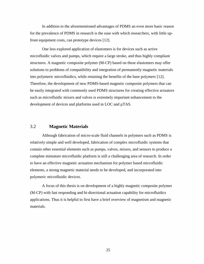
25
In addition to the aforementioned advantages of PDMS an even more basic reason
for the prevalence of PDMS in research is the ease with which researchers, with little up-
front equipment costs, can prototype devices [12].
One less explored application of elastomers is for devices such as active
microfluidic valves and pumps, which require a large stroke, and thus highly compliant
structures. A magnetic composite polymer (M-CP) based on these elastomers may offer
solutions to problems of compatibility and integration of permanently magnetic materials
into polymeric microfluidics, while retaining the benefits of the base polymers [12].
Therefore, the development of new PDMS-based magnetic composite polymers that can
be easily integrated with commonly used PDMS structures for creating effective actuators
such as microfluidic mixers and valves is extremely important enhancement to the
development of devices and platforms used in LOC and µTAS.
3.2 Magnetic Materials
Although fabrication of micro-scale fluid channels in polymers such as PDMS is
relatively simple and well developed, fabrication of complex microfluidic systems that
contain other essential elements such as pumps, valves, mixers, and sensors to produce a
complete miniature microfluidic platform is still a challenging area of research. In order
to have an effective magnetic actuation mechanism for polymer based microfluidic
elements, a strong magnetic material needs to be developed, and incorporated into
polymeric microfluidic devices.
A focus of this thesis is on development of a highly magnetic composite polymer
(M-CP) with fast responding and bi-directional actuation capability for microfluidics
applications. Thus it is helpful to first have a brief overview of magnetism and magnetic
materials.

26
3.2.1 Background
Some of the most common ways to classify magnetic properties of materials
include the response of a material to the presence of an external magnetic field, relative
permeability, and relative susceptibility. Ferromagnetic materials such as iron, nickel, and
cobalt have regions in the bulk material, called magnetic domains, which make these
materials sensitive to external magnetic fields. Within the magnetic domains, the
magnetic moments of the atoms are aligned with each other (Figure 2). These domains
initially have random orientations, cancelling each other out and resulting in no net
magnetic field in the material. However, by applying an external magnetic field, these
domains align themselves in parallel to the magnetic field in a process known as
magnetization. There is a maximum temperature, known as the Curie temperature, above
which these materials lose their ferromagnetic properties and becomes paramagnetic.
Figure 2: Schematic of domains in ferromagnetic material (top) before, and (bottom) after
magnetization.
Ferromagnetic materials can be classified based on their saturation magnetization,
coercivity, remanent magnetization, and relative permeability [12,100]. In order to further
discuss magnetic materials and their properties, we need to first briefly define each of
these parameters. Figure 3 shows the B-H curves of ferromagnetic materials, in which
is the amplitude of the externally applied magnetic field, , with SI unit of A/m, and is
the amplitude of the total magnetic flux density curve, , with SI unit of Wb/m2,

27
presented within the material. This curve, also known as Demagnetization Curve,
describes the conditions, under which a ferromagnetic material is magnetized, the
strength of the magnetization, and the susceptibility to being demagnetized. The area
enclosed by the curve is what is known as the hysteresis loop, which is the energy
dissipated per unit volume per cycle of applied field oscillation. The hysteresis loop is the
closed loop obtained when the material is cycled between positive and negative magnetic
saturation, which is reached when an increase in magnetization field, H, no longer causes
an increase in the magnetic flux density, B, of the material.
Figure 3: Magnetic flux density (B) versus magnetic field strength (H) hysteresis curve of
ferromagnetic materials.
In Figure 3, one can see that when the external field is zero, the flux density
in the ferromagnetic material is which is the residual flux density or remnant
magnetization [4]. It is also customary to plot the magnetization of a material, M, as a
function of the magnetization field, H, which can be seen in Figure 4. When a
ferromagnetic material is magnetized in one direction, it is possible that the material does
not relax back to zero magnetization when the imposed magnetizing field is removed.
Instead, the ferromagnetic material can retain a considerable degree of magnetization and

28
it must be driven back to zero by a field in the opposite direction. The reverse external
field, Hc, which is also called coercivity or coercive force, is required to demagnetize the
material and make M zero. The dashed black line in Figure 4 shows the nonlinear
magnetization curve when the material is magnetized from a zero field value.
Figure 4: The magnetization, M, versus magnetic field strength, H, hysteresis curve of
ferromagnetic materials.
As previously mentioned, magnetic materials can be classified based on their
saturation magnetization, coercivity, remanent magnetization, and relative permeability
[12,100]. Based on the B-H behavior of the magnetic materials, they can be classified into
two categories: soft- and hard-magnetic materials. Soft magnetic materials are
characterized by a high permeability and a low coercivity (Hc< 1000 A/m) [101]. Hard
magnetic materials have a relatively low permeability and a high coercivity (Hc >10000
A/m) [101]. Soft-magnetic materials, such as nickel-iron, carbon-iron, and silicon-iron,
can be magnetized and demagnetized easily and with relatively low magnetic field
intensity, and they do not tend to stay magnetized when the external magnetic field is
removed. As shown in Figure 5, the hysteresis loop in these materials is narrow. Soft-
magnetic materials are suitable for applications when a series of
magnetization/demagnetization cycles are required [12,100,102].
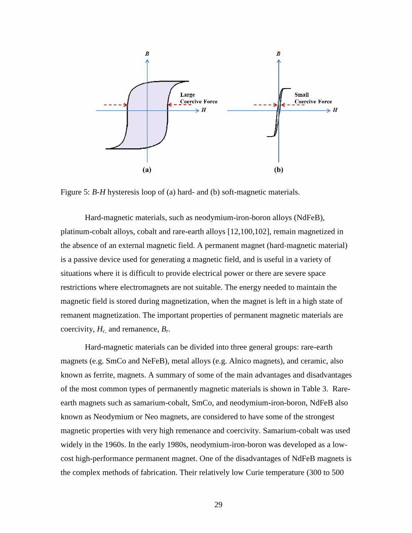
29
Figure 5: B-H hysteresis loop of (a) hard- and (b) soft-magnetic materials.
Hard-magnetic materials, such as neodymium-iron-boron alloys (NdFeB),
platinum-cobalt alloys, cobalt and rare-earth alloys [12,100,102], remain magnetized in
the absence of an external magnetic field. A permanent magnet (hard-magnetic material)
is a passive device used for generating a magnetic field, and is useful in a variety of
situations where it is difficult to provide electrical power or there are severe space
restrictions where electromagnets are not suitable. The energy needed to maintain the
magnetic field is stored during magnetization, when the magnet is left in a high state of
remanent magnetization. The important properties of permanent magnetic materials are
coercivity, Hc, and remanence, Br.
Hard-magnetic materials can be divided into three general groups: rare-earth
magnets (e.g. SmCo and NeFeB), metal alloys (e.g. Alnico magnets), and ceramic, also
known as ferrite, magnets. A summary of some of the main advantages and disadvantages
of the most common types of permanently magnetic materials is shown in Table 3. Rare-
earth magnets such as samarium-cobalt, SmCo, and neodymium-iron-boron, NdFeB also
known as Neodymium or Neo magnets, are considered to have some of the strongest
magnetic properties with very high remenance and coercivity. Samarium-cobalt was used
widely in the 1960s. In the early 1980s, neodymium-iron-boron was developed as a low-
cost high-performance permanent magnet. One of the disadvantages of NdFeB magnets is
the complex methods of fabrication. Their relatively low Curie temperature (300 to 500
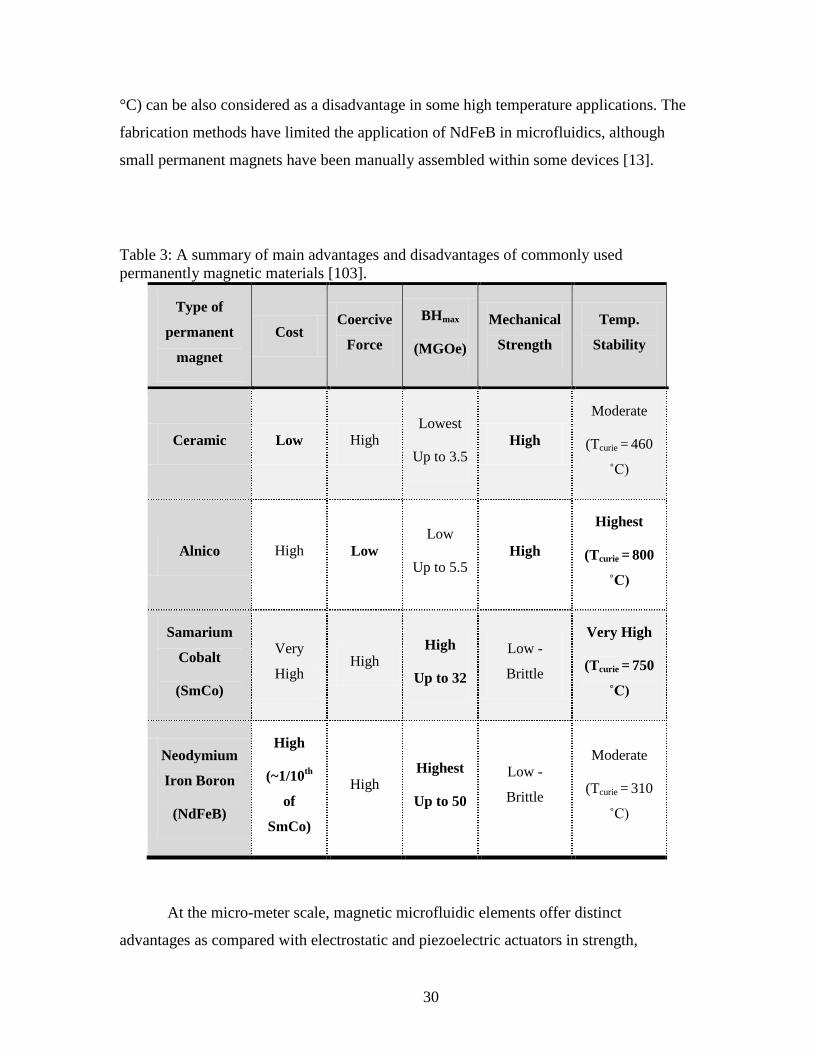
30
°C) can be also considered as a disadvantage in some high temperature applications. The
fabrication methods have limited the application of NdFeB in microfluidics, although
small permanent magnets have been manually assembled within some devices [13].
Table 3: A summary of main advantages and disadvantages of commonly used
permanently magnetic materials [103].
Type of
permanent
magnet
Cost Coercive
Force
BHmax
(MGOe)
Mechanical
Strength
Temp.
Stability
Ceramic Low High Lowest
Up to 3.5 High
Moderate
(Tcurie = 460
˚C)
Alnico High Low Low
Up to 5.5 High
Highest
(Tcurie = 800
˚C)
Samarium
Cobalt
(SmCo)
Very
High High
High
Up to 32
Low -
Brittle
Very High
(Tcurie = 750
˚C)
Neodymium
Iron Boron
(NdFeB)
High
(~1/10th
of
SmCo)
High Highest
Up to 50
Low -
Brittle
Moderate
(Tcurie = 310
˚C)
At the micro-meter scale, magnetic microfluidic elements offer distinct
advantages as compared with electrostatic and piezoelectric actuators in strength,
31
polarity, and distance of actuation [13]. Therefore, incorporating strong magnetic
materials, such as rare-earth magnets, as the actuating element to the microfluidic
systems offer new capabilities and open new markets within many application fields.
3.3 Magnetic Composite Polymer
Many previously reported magnetically actuated microfluidic components
integrate soft-magnetic materials into the design of the device [19,104–108]. Use of soft-
magnetic ferrite composite materials for magnetic actuation in microfluidic systems has
been previously explored by many other researchers [19,104–108]. Ferrite-composite
materials are a type of composite polymer whereby a powder (in this case Fe-based) is
integrated into a polymer matrix. Such materials retain many characteristics of the
polymer, yet are provided functionality (in this case magnetism) due to the integrated
powder [12]. However, due to much lower coercivity and magnetic saturation levels of
soft-magnetic materials, they are only capable of producing lower forces (and lower
displacements) when actuated under the same external magnetic field as compared to
hard-magnetic materials. Hard-magnetic materials result in stronger magnets due to
higher coercivity and saturation level [12,100,102]. The use of rare-earth permanent
magnetic materials for microfluidics has been the subject of far less investigation. This is
mainly due to the difficulty in integrating rare-earth materials with polymers.
Many previously reported actuators for devices such as microfluidic valves and
pumps that are fabricated using hard-magnetic materials are based on either integration of
a piece of solid magnet into the design of the device [20,21] or electro plating or
depositing the (solid, non-powder) magnetic material on the top surface of a polymer to
create a thin layer of magnetic film [22,23]. Integration of solid magnetic pieces into a
device faces difficulties including: low accuracy and reliability in assembly process,
difficulty re-producing device behavior, especially as the complexity of the overall
system increases, and limits in scale to magnets greater than about 1 mm in diameter [12].
Electroplating or depositing a thin layer of magnetic material is also difficult; in addition
to the technical difficulty in the deposition of any magnetic material, deposited thin film

32
layers usually suffer from weak adhesion, which leads to delamination of the layer,
and/or micro-cracks, which can lead to failure. These problems are even more profound
for thin magnetic films that are fabricated on flexible elastomeric substrates such as
PDMS [24]; however, these problems of materials mismatch exist even when less
compliant polymers are used.
Rare-earth magnetized materials, such as the (Nd0.7Ce0.3)10.5 Fe83.9B5.6 (MQFP-12-
5 magnetic powder from Magnequench International Inc.) used in this work, not only
have higher magnetic saturation compared to the alternative Fe-based soft-magnetic
materials, but also demonstrate up to four times the magnetic remanence of isotropic
ferrite materials and two times the remanence of anisotropic ferrite powders [24].
A typical coercivity (Hci) and remanent magnetization (Mr) hysteresis loop at 300
K is provided by Khosla and presented in [24]. The hysteresis loop is found to be
reproducible and different samples from the same magnetic polymer batch do not show
any significant variation, indicating that the MQFP particles are homogenously dispersed
in PDMS [24]. The coercivity of M-CP, Hci = 5260 ± 30 Oe, is found to be very close to
that of pure 5-10 micrometer NdFeB powder with a coercivity of Hci = 5325 Oe [24].
Furthermore, composite polymers based on these materials overcome difficulties
in fabrication, assembly, and weak adhesion associated with other methods of integrating
hard magnetic materials into polymer systems. Structures made with this permanent
magnetic powder can be actuated in much smaller magnetic fields than the same
structures made with soft-magnetic powder. Alternatively, much higher actuator
displacement can be achieved for the same magnetic field. Furthermore, soft-magnetic
materials can only produce attraction forces when actuated in an external magnetic field,
as they easily demagnetize upon removal of the external magnetic field due to their low
remanence. Hard-magnetic materials are capable of both attraction and repulsion forces,
due to their high remanence, allowing them to remain permanently magnetized [12,102].
Compared to soft-magnetic composite polymers based on ferrites, therefore, the primary
advantages of permanently magnetized rare-earth composite polymers are the creation of
larger displacement and bi-directional actuation, making it possible to fabricate more
complex, energy-efficient, and bi-stable components. The use of hard-magnetic materials

33
also helps to provide larger actuation forces over longer distances [12,109]. Therefore,
hard-magnetic materials offer very desirable characteristics for many applications of
micro-actuators, including microfluidic valves and mixers.
Development of polymeric microfluidic components that employ actuators
fabricated in hard-permanently-magnetic materials and can be more easily integrated with
other polymeric components in a microfluidic system are essential to harness the full
benefits of hard-magnetic materials for microfluidic applications. In this work, such an
effective and compatible material is achieved by combining rare-earth magnetic powder
with PDMS to produce a magnetic composite polymer (M-CP) that can be permanently
magnetized, providing both the advantages of hard-magnetic material previously
mentioned, as well as the compliance and flexibility of PDMS. This material is then used
in a number of microfluidic actuators to demonstrate that this material can result in highly
effective actuator that can be easily integrated with PDMS-based microfluidic devices
and systems.
In order to create effective permanently magnetic composite polymers with
uniform magnetic and mechanical properties, PDMS (Sylgard 184 Elastomer Kit
purchased from Dow Corning) is doped with rare-earth magnetic powders, (Nd0.7Ce0.3)10.5
Fe83.9B5.6 (MQFP-12-5 magnetic powder from Magnequench International Inc.), with a
grain size in the range of 5 to 10 micrometers. The magnetic powder is uniformly
dispersed with a weight percentage of 80 wt-% in the PDMS (the highest wt-% with
reliable curing). In order to achieve uniformity of dispersion, the magnetic powder is first
manually stirred into the PDMS monomer for 10 minutes, and then oscillated by
ultrasonic waves for 5 minutes. The curing agent is then added to the mixture in a ratio of
1.5:10, curing agent: magnetic composite monomer, by weight. Previous studies show
that solvent assisted dispersion is not required [24,110]. The resulting M-CP mixture is
then degassed in a vacuum chamber for a minimum of 30 minutes to remove air bubbles
that are trapped in the polymer during the vigorous mixing process [85,109–112]. The
standard mold for un-doped PDMS is SU-8 photo-patternable epoxy. It is discovered
experimentally that the M-CP material, unlike un-doped PDMS, shows strong adhesion to
SU-8 surfaces, making it impractical to demold the actuator from micro-molds made out
of SU-8. As a result, PMMA molds, fabricated using laser ablation using a Universal

34
Laser System’s VersalLASER©
, are used instead. These molds allow successfully micro-
molding of the M-CP structures without the use of a releasing reagent. Using this simple
dispersion technique, no agglomeration is observed on SEM photographs or SQUID
magnetometer [24].
Magnetic and mechanical properties of the M-CP need to be fully characterized in
order to achieve optimized designs for the actuators that use this M-CP. Therefore, three
sets of characterization tests are performed to better evaluate the mechanical
characteristics and magnetic force interactions of the M-CP material. First, the elasticity
of the doped M-CP material is determined using a tensile test to find the Young’s
modulus (modulus of elasticity) of the material as a function of the doping level (weight
percentage of magnetic particles) [109]. Second, the relationship between material
thickness and magnetic force produced is found. Finally, the strength of the magnetic
field is measured at different distances from the M-CP surface.
3.3.1 Material Characterization1
The results reported in this section are needed for effective design, fabrication,
and operation of M-CP microfluidic actuators, as well as future optimization of the
design and performance of M-CP actuators. More generally, the results presented in this
section are also intended to aid in development of other microfluidic components
utilizing the same M-CP and hybrid M-CP/PDMS fabrication processes. Some of the key
magnetic properties of the NdFeB/PDMS magnetic composite polymer have already been
characterized previously by our research group [24]. These results include
characterization of coercivity (Hci = 5260 ± 30 Oe), remanent magnetization (Mr = 59.7
emu/g) and magnetization (M) vs. coercitvity (H) hysteresis loop [24]. However, in order
to successfully model and optimize actuator designs, certain mechanical characteristics of
the M-CP material are also needed, as well as characterizations of magnetic and
mechanical force interactions. Such characterization is especially useful for supplying
1 Some of the material and data presented in this section are adapted from [109].
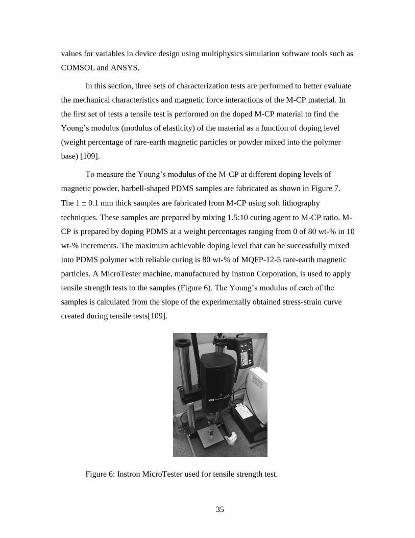
35
values for variables in device design using multiphysics simulation software tools such as
COMSOL and ANSYS.
In this section, three sets of characterization tests are performed to better evaluate
the mechanical characteristics and magnetic force interactions of the M-CP material. In
the first set of tests a tensile test is performed on the doped M-CP material to find the
Young’s modulus (modulus of elasticity) of the material as a function of doping level
(weight percentage of rare-earth magnetic particles or powder mixed into the polymer
base) [109].
To measure the Young’s modulus of the M-CP at different doping levels of
magnetic powder, barbell-shaped PDMS samples are fabricated as shown in Figure 7.
The 1 0.1 mm thick samples are fabricated from M-CP using soft lithography
techniques. These samples are prepared by mixing 1.5:10 curing agent to M-CP ratio. M-
CP is prepared by doping PDMS at a weight percentages ranging from 0 of 80 wt-% in 10
wt-% increments. The maximum achievable doping level that can be successfully mixed
into PDMS polymer with reliable curing is 80 wt-% of MQFP-12-5 rare-earth magnetic
particles. A MicroTester machine, manufactured by Instron Corporation, is used to apply
tensile strength tests to the samples (Figure 6). The Young’s modulus of each of the
samples is calculated from the slope of the experimentally obtained stress-strain curve
created during tensile tests[109].
Figure 6: Instron MicroTester used for tensile strength test.

36
Figure 7: This photo shows the shape and dimensions of two of the M-CP samples used
for tensile strength testing. The samples’ thicknesses are 1 ± 0.1 mm. Sample doping
level ranged from 0 to 80 wt-% in 10 wt-% increments. The two wider ends are used to
clamp the samples to the Instron MicroTester machine.

37
Figure 8 shows a typical stress-strain curve form 80% doped M-CP material.
Figure 8: A typical stress-strain curved produced by Instron MicroTester for 80% doped
M-CP.
As discussed later in Section 5.2.5 the M-CP actuators described in this thesis
work at pressures in kPa range. Therefore, according to the stress-strain curve for 80%
doped M-CP shown in Figure 8 these actuators work at the linear region for M-CP
material.
Nine measurements are taken to calculate the average Young’s modulus at each
wt-%. The results of these measurements are presented Table 4 and Figure 9.

38
Table 4: Calculated Young’s modulus values for each tested sample.
Doping
level of
PDMS
(wt-%)
Young’s Modulus for Sample # Average
Young’s
Modulus
(MPa)
Standard
Deviation 1 2 3 4 5 6 7 8 9
0 0.50 0.63 0.46 0.47 0.50 0.54 0.52 0.62 0.46 0.522 0.0653
10 1.05 0.92 0.95 0.95 0.91 1.08 1.08 0.94 0.99 0.985 0.0684
20 1.04 1.17 1.00 1.09 1.16 1.19 1.12 1.10 1.17 1.115 0.0672
30 1.21 1.28 1.28 1.13 1.02 1.28 1.13 1.14 1.19 1.184 0.0904
40 1.23 1.26 1.32 1.40 1.27 1.32 1.19 1.12 1.26 1.263 0.0790
50 1.26 1.36 1.35 1.50 1.37 1.44 1.29 1.44 1.40 1.380 0.0737
60 1.54 1.47 1.30 1.44 1.51 1.43 1.49 1.35 1.42 1.439 0.0753
70 1.47 1.48 1.62 1.54 1.67 1.62 1.56 1.56 1.53 1.562 0.0658
80 1.59 1.60 1.51 1.67 1.63 1.70 1.65 1.63 1.61 1.623 0.0548
As shown in Figure 9, the un-doped PDMS (0 wt-%) has the lowest Young’s
modulus and hence the highest elasticity. As the doping level increases, the Young’s
modulus of M-CP increases which correlates to a decrease in the elasticity of the doped
PDMS. This is as expected, as a similar trend has been noticed by other researchers using
different particles in PDMS polymer matrix [106].

39
Figure 9: Young’s modulus versus doping percentage of particles in M-CP using samples
as illustrated in Figure 7. Horizontal error bars represent ± 1% accuracy in PDMS doping
level and vertical error bars represent one standard deviation over 9 samples at each
doping level. This image is adapted from [109].
In order to further characterize the permanently magnetized M-CP, samples with
the maximum doping concentration of 80 wt-% are used to measure the
attraction/repulsion force between a permanent magnet and samples of M-CP (with
different cross-sectional dimensions) under a 80 mT external magnetic field. Samples 2
2 mm2 in size (length width) with thicknesses ranging from 0.09 to 0.64 mm are
patterned and tested. The attraction/repulsion forces are measured by fixing the M-CP
squares shown in Figure 10 on a scale and actuating them under an 80 mT external
magnetic field. The change in measured weight due to attraction/repulsion force between
the permanently magnetized M-CP and the permanent magnet is measured and converted
into the force. The results of this test are shown in Figure 10 and Table 5. An external
magnetic field of 80 mT is used for these characterization tests, as this is equivalent to the
magnetic field that is used for actuation of the valve flaps discussed in Section 5.2. Table
5 and Figure 11 show the relationship between the M-CP sample thickness and
attraction/repulsion force created under an externally applied 80 mT magnetic field.

40
Figure 10: Illustration of the samples used to measure magnetic attraction/repulsion
forces between M-CP samples (with different thicknesses) and an 80 mT external
magnetic field.
Table 5. The attraction/repulsion forces between samples of permanently magnetized M-
CP (doped at 80 wt-% and sized as in Figure 10) and an external actuation magnetic field
of 80 mT (provided by a miniature permanent magnet). Sample cross-sectional
dimensions are 2 2 mm2.
Sample thickness
(mm)a
The attraction/repulsion
force (mN)b
0.09 1.323
0.10 1.519
0.14 1.715
0.17 2.156
0.20 2.646
0.22 2.842
0.29 4.067
0.31 4.459
0.35 5.586
0.39 6.321
0.41 6.909
0.46 7.840
0.53 9.604
0.57 10.682
0.64 11.907 aAll the thickness values have an accuracy of ± 0.01 mm.
bThe values presented in this table are the average values obtained from 5 measurements
on 5 different M-CP samples for each thickness.

41
Figure 11: Relationship between M-CP sample thickness and the attraction/repulsion
force exerted on each permanently magnetized M-CP sample doped at 80 wt-% and
actuated under an 80 mT external magnetic field. The horizontal error bars represent ±
0.01 mm accuracy for thickness and the vertical error bars represent one standard
deviation over 5 measurements at each point. Horizontal error bars present ± 0.025 µm
variation in the sample thicknesses.
The flux density for cylindrical M-CP magnets such as the example shown in
Figure 12 can be estimated using the following formula:
(3.1)

42
where Br is remanence field, z is the distance from the face, D is the height of the
cylinder, and R is the radius of the cylinder.
Figure 12: Illustration of a cylindrical permanently magnetized M-CP with a radius of R,
and height of D.
At the surface of M-CP, z=0, the formula can be simplified as:
(3.2)
For simplification we use the relationship between the magnetic flux density and
force between two nearby magnetized surfaces of area A shown in Equation 3.3 to
roughly show the relationship between the magnetic force and magnet’s thickness.
(3.3)

43
where A is the area of each surface, µ0 is the permeability of space, which equals 4π×10−7
T·m/A, and B is the flux density.
Figure 13 shows simplified and normalized relationship between the magnetic
force and magnet thickness. The curvature of Figure 13 is similar to the curvature of
experimentally measured data shown in Figure 11.
Figure 13: Normalized relationship between the force between the two magnetized
surfaces and magnet thickness.
Finally, the magnetic field produced by each sample is measured at different
distances from the sample’s surface in the absence of any external magnetic fields. These
values are measured using a 5180 Hall Effect portable Gauss/Tesla meter by F.W.
BELL®
. The setup for these experiments is shown in Figure 14, and the results of these
measurements are shown in Figure 15. The distance between the M-CP top surface and
the tip of the Hall Effect sensor used for these measurements is denoted as the gap size in
Figure 14.

44
Figure 14: Schematic of the setup used to measure the magnetic field created by each M-
CP sample with different thicknesses at different gaps (distance between the sample and
Gauss/Tesla meter).
Figure 15: Magnetic field produced by samples of permanently magnetized M-CP (doped
at 80 wt-%, and of different thicknesses) in the absence of any external magnetic field.
Gap size is defined as the distance between the top surface of the M-CP sample and the
tip of the Hall Effect sensor (see Figure 14). M-CP cross-sectional dimensions are 2 2
mm2, with different thicknesses as shown in the legend.
Figure 11 shows that thicker M-CP samples experience higher attraction forces
under the same external actuating magnetic field, which is very desirable for creation of
effective microfluidic actuators. On the other hand, a thinner layer is expected to be
mechanically more flexible. These results can be used to optimize the design of the
actuators based on the specific application. An example of such optimization will be
shown in Chapter 5, where a step-shaped flap design is used for the microfluidic valve to

45
best take advantage of both the flexibility of a thin M-CP flap actuator and the high
magnetic force of a thicker flap actuator.
3.4 Chapter Summary and Conclusions
This chapter provides background information on the polymer and magnetic
materials employed throughout the thesis, and includes details on fabrication of a
magnetic composite polymer (M-CP) based on rare-earth magnetic powder. Mechanical
and magnetic characteristics of the M-CP are evaluated by performing several tests. A
MicroTester machine, manufactured by Instron Corporation, is used to perform tensile
strength tests on M-CP samples, allowing experimental determination of the M-CP
material stress-strain curve and the Young’s modulus of the M-CP material at different
doping concentrations. The experimental results of the characterization tests confirm that
un-doped PDMS has the highest flexibility, while increasing the doping concentration
reduced the flexibility of the material. The relationship between material thickness and
magnetic force between the M-CP under an external magnetic field is experimentally
determined through force measurements on M-CP samples. M-CP samples are also used
to measure the strength of the magnetic field produced by the permanently magnetized
M-CP at different distances from the M-CP surface. In the next three chapters it is
explained how each of these characterization results, and the various properties of the M-
CP material, are used for design and optimization of the different types of M-CP
actuators developed in this thesis.
3.5 Related Publications
Some results of the work presented in this section have been presented in details in
the following peer reviewed publication:
1. Rahbar, M., Seyfollahi, S., Khosla, A., Shannon, L., Gray, B. L.,
“Fabrication Process for Electromagnetic Actuators Compatible with Polymer
Based Microfluidic Devices,” ECS Transactions, The Electrochemical
Society, 41, 2012.

46
Chapter 4 - Ultra-high Aspect-ratio Bio-inspired Artificial
Cilia Actuator2
Throughout millions of years of evolution, nature has combined natural resources
with effective designs to survive and overcome obstacles. Nature’s solutions and designs
have been a great source of inspiration that has pushed the boundaries and advanced
technologies throughout human history. In nature, a great number of organisms have
developed micro-structures called cilia and flagella in order to be able to effectively
manipulate small volumes of fluid and achieve different goals. These natural structures
can be found in micro- as well as macro-organisms, and they range in length from a few
micrometers to a few millimeters [113]. These structures are used for different functions,
including: by mammalian spermatozoon and unicellular protozoan, paramecium, to move
the organism; by paramecium to bring in food; by eukaryotes to sense mechanical and
chemical signals from the extracellular environment; by mammals in many organs such
as mammalian cochlear (in the inner ear) for detection of vibration caused by sound; and
to move fluid or sweep particles across a tissue surface such as epithelial cells in
mammalian respiratory surfaces to move the mucosal secretions of these tissues [90,113–
115]. Similarly, in microfluidic applications, high aspect-ratio cilium-like structures, or
artificial cilia, are used for many crucial applications which require the manipulation of
small volumes of fluid [112,116]. Artificial cilia structures can be used for applications
including object manipulation and transportation [91,117], microfluidic pumps [118,119]
and microfluidic mixers [91,92,106,116].
Various cilia structures and actuation approaches have been previously investigated
by a number of researchers. Some of the previously used actuation techniques include
magnetic force [19,92]; piezoelectric actuators to oscillate a reaction chamber containing
artificial cilia structures [91,120,121]; and electrostatic forces [90,116,122]. Although
each of these previously reported techniques are shown to be capable of performing the
2 Part of the research presented in this chapter is based on research previously published in [111]
and [112]. Those parts are author-created, un-copyedited version of the article accepted for publication in
Journal of Micromechanics and Microengineering. IOP Publishing Ltd is not responsible for any errors or
omissions in this version of the manuscript or any version derived from it. The Version of Record is
available online at [http://dx.doi.org/10.1088/0960-1317/24/2/025003].

47
required actuation to some degree, they still have limitations and disadvantages
associated with each of them. Some of these disadvantages include: complication in
fabrication process, complication in integration with other existing microfluidic elements,
difficult or impractical implementation of actuation scheme, and low actuation efficiency.
High aspect-ratio, highly flexible, and highly magnetic cilia structures can address many
of these problems [24]. Such high aspect-ratio and flexible artificial cilia structures
should be fabricated using a fabrication technique with minimum possible complexity
and compatibility with existing and commonly used microfluidic systems. Furthermore,
cilia structures should be highly controllable and provide wide range of motion, while
actuated under relatively small stimuli which can be locally applied.
Previously studied magnetic cilia structures [19,91,92,116–118,123] employ a wide
variety of fabrication methods such as: soft lithography techniques that mold magnetic
polymers against masters molds [19], magnetically assembling of magnetic polymer cilia
in a liquid polymer bath [117], multi-step surface micro-machining processes
[116,122,123] and 3D printing of cilia like structures [106]. However, many of these
previously explored magnetically actuated artificial cilia actuators suffer from limiting
factor that are related to one or a combination of the following factors:
Complexity of fabrication and/or integration with other microfluidic systems
Low efficiency in the actuator’s performance
Impractical or hard to implement magnetic actuation mechanism
Use of weak magnetic materials, i.e. soft-magnetic materials, such as iron
instead of hard-magnetic materials, which as previously discussed can greatly
affect the actuator’s performance
Therefore, development of effective microfluidic artificial cilia actuator based on
hard-magnetic materials, employing a relatively simple fabrication technique that is
compatible with existing microfluidic structures, fabrication techniques, and materials,
would be an important contribution to the microfluidic field and the future of LOC and
µTAS as a whole.
To address the aforementioned limitations, a novel fabrication technique is developed
for the rare-earth magnetic composite polymer (M-CP) discussed in Section 3.3, to
achieve ultra-high aspect-ratio artificial cilia structures using poly(ethylene glycol) (PEG)
as sacrificial mold. The performance of these artificial cilia actuators as microfluidic
48
mixers within microfluidic structures are experimentally characterized and compared to
passive mixing using only diffusion, as well as to other previously reported artificial cilia
mixers.
The novel fabrication technique developed in this work is relatively simple, low cost,
and scalable for high throughput large scale manufacturing, and for making multiple
mixing areas on a device such as may be required for the µROAMS project. The resulting
artificial cilia actuators can be actuated using relatively low magnetic fields of 7 mT,
allowing for the use of miniature electromagnets suitable for LOC and µTAS applications
and compatible with the µROAMS project magnetic field generation device currently
under development. Since the artificial cilia can be fabricated and magnetically polarized
directly inside the microfluidic system, they can be easily integrated with complex
polymer based microfluidic systems.
The discussions presented in this chapter are based on the work that has been
published in [114] and [115].
4.1 Artificial Cilia Design and Fabrication
To create cilia structures suitable for use in microfluidic mixing, a novel
fabrication technique is developed that is relatively straightforward, effective, and allows
for easy integration of cilia structures into a polymer microfluidic device. Two examples
of such structures are shown in Figure 16. Figure 16(a) shows a cilium actuator fabricated
inside a reaction chamber and Figure 16(b) shows a cilium actuator created directly inside
a 400 µm wide microfluidic channel. The fabrication technique can be scaled up for
volume production, does not require any complex assembling steps, and results in
fabricated cilia structures at the desired location directly inside of the microfluidic device.
It is also compatible with other fabrication techniques commonly used for PDMS based
microfluidics, as well as fabrication techniques used for other devices using similar
composite polymer technologies [12,24,85,109,124–126].

49
Figure 16: Artificial cilia fabricated directly inside (a) a microfluidic reaction chamber,
and (b) a microfluidic channel.
In this work, devices that are fabricated for testing of the performance of the
artificial cilia actuator as microfluidic mixer consist of a reaction chamber and cilia
actuators fabricated inside the chamber. The mixer performance is characterized by
recording the mixing of two colored liquids.
Figure 17: Schematic of a sample microfluidic reaction chamber used for performance
characterization tests on the microfluidic mixers based on artificial cilia actuators.
In the first step, a PDMS reaction chamber is fabricated using standard soft
lithography techniques. The magnetic composite polymer is prepared by following the
same process steps previously explained in Section 3.3. After preparation of the M-CP by
uniformly dispersing the magnetic particles, (Nd0.7Ce0.3)10.5Fe83.9B5.6, into the PDMS
matrix, the process steps shown in Figure 18 are followed to fabricate the cilia structures
directly inside the microfluidic chamber. The maximum 80 wt-% doping of magnetic
particles is employed.
To fabricate the artificial cilia directly inside the reaction chamber, the desired
location is first filled with poly(ethylene glycol) (PEG). PEG is a water-soluble, bio-

50
compatible and nontoxic polymer which is used in many pharmaceutical, food, and
cosmetic applications, such as hydrogel fabrication, which makes PEG suitable for
fabrication processes in microfluidic applications. Many different types of PEG with
various molecular weights are commercially available. The PEG product used in this
fabrication process is selected to have relatively high molecular weight and melting point
(from Sigma-Aldrich® with average Mn = 2050 and melting point of 52 – 54ºC). The
high melting point is required to ensure that the PEG sacrificial mold remains solid
throughout the entire fabrication and handling process. The PEG is first melted at 80 ºC
on a hotplate. The liquid PEG is then poured on the sections of the microfluidic system in
which the cilia mixer is going to be fabricated in the future steps (in this case, inside the
reaction chamber). After being filled with melted PEG, the chamber is immediately
covered with a thin sheet of aluminum (thickness < 0.2 mm) to achieve a surface
roughness of less than 15 μm. The PEG is allowed to cool and solidify at room
temperature for 10 minutes (Figure 18 (b)-(e)). In the next step, micro-needles with
diameters of 120 μm are inserted into the chamber (Figure 18 (f)). The 120 µm micro-
needles are the smallest diameter micro-needle available to us for this fabrication,
although the process is capable of accepting smaller sized needles. M-CP is then poured
over the micro-needles, and the needles are slowly removed. The vacuum created as the
result of the evacuating micro-needles draws the M-CP into the mold, filling all voids.
The sample is placed under vacuum for 30 minutes to ensure that there are no trapped air
bubbles. Afterwards, the excess M-CP on the surface is scraped off, the thin aluminum
layer is peeled off, and the sample is allowed to cure at room temperature for a minimum
of 24 hours (Figure 18 (i)-(j)). For the M-CP preparation, the Dow Corning® 184 Silicone
Elastomer kit is used, which has a working time of 1.4 hours at 25 ºC. This relatively
short working time at room temperature (25 ºC) allows us to fully cure the M-CP at
room temperature within a reasonable time (24 hours) without damaging the PEG mold.
In the last step, the PEG mold is dissolved in 60 ºC water. An external permanent magnet
keeps the cilia in an upright position while the water is removed using a nitrogen gun,
avoiding any collapse of the structures during drying due to the surface tension of water
or blow drying.
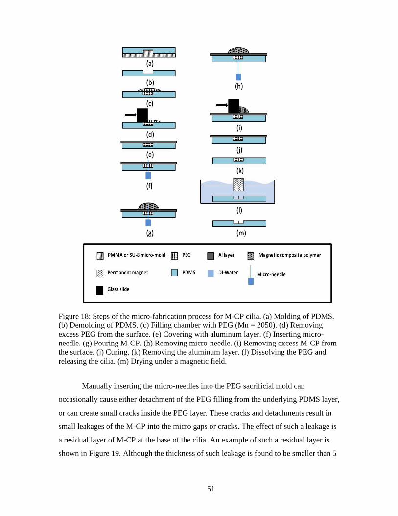
51
Figure 18: Steps of the micro-fabrication process for M-CP cilia. (a) Molding of PDMS.
(b) Demolding of PDMS. (c) Filling chamber with PEG (Mn = 2050). (d) Removing
excess PEG from the surface. (e) Covering with aluminum layer. (f) Inserting micro-
needle. (g) Pouring M-CP. (h) Removing micro-needle. (i) Removing excess M-CP from
the surface. (j) Curing. (k) Removing the aluminum layer. (l) Dissolving the PEG and
releasing the cilia. (m) Drying under a magnetic field.
Manually inserting the micro-needles into the PEG sacrificial mold can
occasionally cause either detachment of the PEG filling from the underlying PDMS layer,
or can create small cracks inside the PEG layer. These cracks and detachments result in
small leakages of the M-CP into the micro gaps or cracks. The effect of such a leakage is
a residual layer of M-CP at the base of the cilia. An example of such a residual layer is
shown in Figure 19. Although the thickness of such leakage is found to be smaller than 5

52
µm on average and shows no significant effect on the performance of the artificial cilia, it
should be avoided for good process control. Also, any significant surface roughness
inside the microfluidic system, such as in the reaction chamber, can potentially act as a
trap where cells and other particles could potentially be trapped or anchored, which can
be undesirable for many applications. Furthermore, the residual M-CP at the base of the
cilia also compromises the transparency of the bottom PDMS surface of the reaction
chamber or microfluidic channel where the cilia are located. In many applications, it is
essential to keep the microfluidic system transparent for visual inspection or optical
monitoring and detection techniques.
Figure 19: Residual layer of M-CP at the base of a cilium. This residual layer is caused
by small cracks that occasionally occur while inserting the micro-needle (cilia diameter =
130 ± 5 µm, cilia height = 1 mm).
The undesired residual layer is eliminated by adding a simple step to the
fabrication process. After inserting the micro-needle into the PEG and PDMS layers
(Figure 18 (f)), the PEG mold is reheated to 70 ºC for 10 min to melt and reflow the PEG
and seal any gap or crack between the PEG sacrificial mold and PDMS layer. After 10
min at 70 ºC, the microfluidic chip is cooled back to room temperature (25 ºC) and
allowed to fully solidify for another 10 minutes.
Figure 20 shows an example of a cilium structure with no residual layer at its base
which is fabricated by following these additional heating and cooling steps.

53
Figure 20: Cilium mixer fabricated by following the extra steps of heating and re-flowing
of the PEG sacrificial mold after the insertion of micro-needles. The re-heating and
cooling steps ensure that there is no crack or gap between the PEG and the underlying
PDMS layer, (cilia diameter = 130 ± 5 µm, cilia height = 1.2 mm).
Automation can also be used to reduce the formation of cracks and other
complications caused by manual manipulation of the samples, improving process control
and reliability as well as greatly increasing the process throughput. The micro-needles
could be inserted individually by a robotic arm, or as an array built into a stamp form.
The stamp form would be useful for fabrication of microfluidic systems containing large
arrays of cilia structures. A conceptual illustration of such stamp is shown in Figure 21.
Such automation should increase the cilia placement precision and should also be more
desirable for high throughput fabrication processes.
Figure 21: A conceptual illustration of micro-needle stamps that could potentially be used
in artificial cilia fabrication.
After fabrication of the cilia structures directly inside a reaction chamber, the M-
CP cilia are permanently magnetized using a custom-made permanent magnet by Dexter
Magnetic Technologies, shown in Figure 22. The M-CP cilia are magnetized by inserting
the entire microfluidic chip containing the cilia into the slot in the middle of the
permanent magnet block. This custom-made permanent magnet provides a magnetic field
of 1.8 ± 0.2 Tesla inside the magnetizing slot. The magnetization is performed on fully
cured M-CP actuators and the possible effects of magnetizing on uncured M-CP is not

54
studied at this point since it is impractical to insert the entire mold into the custom made
magnetizer due to the small opening of the magnetizer as shown in Figure 22.
Figure 22: Custom made permanent magnet by Dexter Magnetic Technologies used to
magnetize M-CP, (Magnetic field = 1.8 ± 0.2 T).
The application of such permanently magnetic polymer materials for fabrication
of cilia structures has not been presented before in the literature, and presents a great
advantage over cilia produced from iron-based and other soft-magnet ferromagnetic
materials [19,109]. These advantages are discussed in more detail in Section 4.3.
Leakage tests are performed to ensure that the holes created on the base of the
reaction chamber via insertion of the micro-needles are properly sealed by the M-CP. The
design of the microfluidic chips used in these leakage tests are shown in Figure 23. The
inlets of these microfluidic chips are connected to a syringe pump (Harvard Apparatus
model 11) using polyurethane tubing fixed to the inlets using silicone sealant. To build up
pressure in the microfluidic channels, the outlet holes are completely sealed using the
same silicone sealant. A dark blue dye is used as the fluid to ensure fluid visibility in the
channel for better visual inspection and detection of leaks. There is no open outlet for the
systems in this setup. As the syringe pushes liquid into the system, the pressure gradually

55
increases inside of the sealed microfluidic system until eventually one part of the system
fails and leakage is visually observed. In ten microfluidic chips that are tested for
leakage, no leakage is observed under or around the area where micro-needles puncture
the PDMS base. Instead, in all ten devices, leakage occurs either at the tube connection
points (i.e. tube to inlet hole connection, or tube to the micro-needle connection at the
syringe pump), or at lead-base junction between the two PDMS layers (Figure 23). The
average leakage pressure is measured to be around 1.5-2 psi (10.34 - 13.8 kPa). As there
is no sign of leakage at the insertion point of the micro-needles, these results show that
the insertion of the micro-needles in the chamber floor do not compromise the integrity of
the reaction chamber, and the insertion holes are fully sealed with the M-CP.

56
Figure 23: Schematic of microfluidic systems used for leakage tests: mixer/reaction
chambers with single cilium actuator fabricated directly inside the chamber. (a) top layer,
(b) bottom layer, (c) top and bottom layer assembled together and bonded using plasma
activation, and (d) cross-sectional view of the final microfluidic device.
To demonstrate the capability of the proposed fabrication technique to create
ultra-high-aspect-ratio structures, cilia structures as tall as 8 ± 0.1 mm with a diameter of
130 ± 5 μm are fabricated (aspect-ratio = 8:0.1 = 61.54). A sample of such a structure is
shown in Figure 24.

57
Figure 24: Ultra-high aspect-ratio cilium in the absence of an external magnetic field
(cilium length = 8 ± 0.1 mm, cilium diameter = 130 ± 5 μm. Aspect-ratio = 8:0.13 =
61.54).
The focus of the cilia structures fabricated in this work is for use in microfluidic
mixers. As the typical height of microfluidic channels and chambers is usually on the
order of hundreds of micrometers, cilia with an aspect-ratio higher than 8:0.13 would not
fit inside typical microfluidic structures. In our sample devices for performing
microfluidic mixing, the cilia lengths are limited by the reaction chamber height of 1.7 ±
0.5 mm. However, considering the ease with which the cilia structures presented in this
work are fabricated, higher aspect-ratios (aspect-ratio > 8:0.13) can be achieved using the
same technique.
As shown in Figure 25, reaction chambers used in the characterization tests
presented in this work are 1.7 ± 0.5 mm in height (HRC) and 4 ± 0.5 mm in diameter
(DRC). The circular shape of the chamber, as well as the chamber dimensions, are chosen
to be compatibility with commonly used microwell plates [11, 15], as well as the multi-
chamber polymerase chain reaction (PCR) microfluidic chip currently under development
in our research group [127]. The mixer chambers in PCR microfluidic system must be
able to hold and mix a minimum volume of 20 µL of reagents.

58
Figure 25: Illustration of a reaction chamber used for the characterization tests presented
in this work. Reaction chamber height is (HRC) = 1.7 ± 0.5 mm and reaction chamber
diameter is (DRC) = 4 ± 0.5 mm.
Various cilia structures are fabricated in this study, ranging in height from 500 µm
to 8 mm, all with a diameter of 130 ± 5 μm. However, only cilia structures with different
heights ranging from 500 µm to 2.8 mm are used in the mixer application, due to the
height of the reaction chamber (HRC = 1.7 ± 0.5 mm). It is observed that cilia structures
with a height between 500 µm and 3.5 mm and a diameter of 130 ± 5 μm (average aspect-
ratio < 3.5:0.13 = 26.92) are rigid enough to stand upright, without any significant
bending, on their own and in the absence of any external magnetic field support. Yet, all
of these samples are extremely flexible and are capable of a full range of motion (90 º
swing of the cilium tip) when actuated under a relatively small magnetic field of 110 mT
provided by a small permanent magnet at the base of the cilium (Figure 26). The cilium
in Figure 27 shows a 2.8 mm long cilium, which is capable of standing upright in the
absence of a magnetic field.
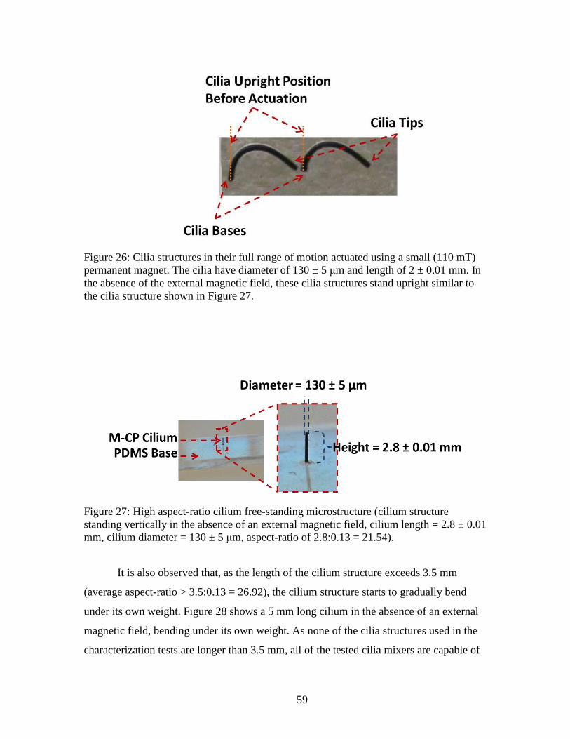
59
Figure 26: Cilia structures in their full range of motion actuated using a small (110 mT)
permanent magnet. The cilia have diameter of 130 ± 5 μm and length of 2 ± 0.01 mm. In
the absence of the external magnetic field, these cilia structures stand upright similar to
the cilia structure shown in Figure 27.
Figure 27: High aspect-ratio cilium free-standing microstructure (cilium structure
standing vertically in the absence of an external magnetic field, cilium length = 2.8 ± 0.01
mm, cilium diameter = 130 ± 5 μm, aspect-ratio of 2.8:0.13 = 21.54).
It is also observed that, as the length of the cilium structure exceeds 3.5 mm
(average aspect-ratio > 3.5:0.13 = 26.92), the cilium structure starts to gradually bend
under its own weight. Figure 28 shows a 5 mm long cilium in the absence of an external
magnetic field, bending under its own weight. As none of the cilia structures used in the
characterization tests are longer than 3.5 mm, all of the tested cilia mixers are capable of

60
staying upright inside the microfluidic system in the absence of an external magnetic
field.
Figure 28: Ultra-high aspect-ratio cilium structure in the absence of an external magnetic
field. (Cilium length = 5 mm, and cilium diameter = 130 ± 5 μm). Although such
structures can be realized, they are not able to stand upright freely in the absence of an
external magnetic field and are not employed as microfluidic mixer elements for this
reason and due to the size of the mixer chamber.
The micro-fabrication technique presented in this work provides control over the
following parameters for fabrication of the artificial cilia: cilium diameter, height,
placement, angle, composition. Control of the fabrication technique over all of these
parameters is discussed below, including theoretical lower limits.
Cilium diameter:
Cilium diameter can be controlled by carefully selecting micro-needles that have
appropriate diameter. In this work, micro-needles with a diameter of 120 µm are used in
the fabrication of the cilium, as they are the smallest diameter easily available. Micro-
needles with larger diameters (D = 350 µm and 820 µm) are also used to demonstrate the
control over the cilia’s diameter (Figure 29).

61
Figure 29: Cilia structures with different diameters fabricated in reaction chambers. (Left)
Cilium diameter = 830 ± 5 µm, (right) cilium diameter = 130 ± 5 µm.
The use of 120 µm micro-needles minimizes the diameter of the cilia structures
given available micro-needle sizes, creating highly flexible cilia structures that can be
effectively actuated by relatively small 7 mT magnetic fields (Figure 30). The micro-
needles used for mixer fabrication (D = 120 µm) result in a cilium diameter of
130 ± 5 µm.
Figure 30: Cilium structure actuated using a 7 mT magnetic field at 60 Hz provided by a
miniature electromagnet (cilium height = 2 ± 0.5 mm and cilium diameter = 130 ± 5 µm).
Cilium height:
As shown in Figure 31 and Figure 32, the height of the cilia actuators can be
controlled by controlling the height of the sacrificial PEG layer. It is also possible to
fabricate cilia of different heights on the same substrate using this process. Figure 32
shows an array of four cilia with four different lengths ranging from 0.8 ± 0.05 mm to 2.2
± 0.05 mm, each with a diameter of 130 ± 5 µm, fabricated on the same substrate and
actuated using a 7 mT miniature electromagnet at 60 Hz. A longer exposure is used while
taking the image in order to show the vibration range in a single image, and show the
control that the new process presented in this work has in terms of individual cilium
placement and size.

62
Figure 31: Cilia actuators with different heights fabricated on the same PDMS substrate
(cilia diameter for all cilia actuators = 130 ± 5 µm. Cilium height from left to right: 0.5 ±
0.1 mm, 1 ± 0.1 mm, 1.8 ± 0.1 mm, and 2 ± 0.1 mm).
Figure 32: An array consisting of four cilia actuators with different sizes actuated using a
7 mT electromagnet at 60 Hz (cilium diameter = 130 ± 5 μm for all four cilia). This
image demonstrates the control over cilia height and placement which is possible with the
new fabrication method, and shows that cilia of different heights have different ranges of
vibrational motion under the 7 mT, 60 Hz magnetic field.
Cilium placement:
One key advantage of this novel and relatively easy fabrication process is that,
unlike many other artificial cilia fabrication techniques previously reported [106,121],
this technique enables cilia structures to be directly fabricated on the PDMS surface
inside the desired location. There is no need for additional assembly steps (Figure 33).

63
Figure 33: Artificial cilia structures fabricated directly inside (a) a microfluidic reaction
chamber, and (b) a microfluidic channel. There is no need to additional assembly as is
required in other cilia fabrication processes [106,121].
Number of cilia per chamber:
The fabrication technique presented in this chapter (Figure 18) also allows for the
placement of multiple cilia simultaneously inside of a desired microstructure, such as a
reaction chamber. This allows for placement in arrays, such as the 2×3 array of six cilia
shown in Figure 34.
Figure 34: A 2 × 3 array of six cilia (cilia diameter = 130 ± 5 μm, cilia height = 1.5 mm,
and gap between the cilia = 1 ± 0.1 mm).
Cilium angle:
By changing the micro-needle’s angle at the insertion point, the cilia can be
fabricated with a specific angle relative to the substrate surface, so that it sits at this angle
in the absence of any magnetic field. For the cilia actuators used for microfluidic mixers
in this dissertation, only vertical (90 º with respect to substrate surface) cilia structures are

64
used. To demonstrate the capabilities of the fabrication technique for fabricating non-
vertical structures, cilia structures with various angles with respect to the substrate
surface are fabricated. Examples of these structures can be seen in Figure 35.
Figure 35: Cilia structures fabricated on the same reaction chamber. Each of the cilia
structures has a different angle with respect to the vertical line (Cilia diameter = 130 ± 5
μm, and cilia height = 1 mm).
Cilium composition: partially doped cilia:
Hybrid cilia structures consisting of both magnetic and non-magnetic segments
can be fabricated on the same device using a modified version of the same fabrication
technique as fully M-CP cilia. As discussed in Section 3.3.1, characterization tests on the
M-CP have shown that doped PDMS has a higher Young’s modulus and hence lower
flexibility compared with un-doped PDMS. In applications where maximum flexibility is
required, it can be beneficial to fabricate a segment of the cilia structures with un-doped
polymer. Figure 36 and Figure 37 show an example of such a device, consisting of three
cilia with different percentages of their length formed from magnetic polymer material,
all in the same microfluidic reaction chamber. The cilia structures shown in Figure 36
consist of 0% (the cilium on the right), 40% (the cilium in the middle) and 100% (cilium
on the left) of the length fabricated from M-CP, with the remainder of the cilium
fabricated from un-doped PDMS. Figure 37 shows the same cilia structures actuated in a
110 mT magnetic field. As shown in this figure, different degrees of actuation range can
be created on a single chip from the same actuation field, based on the application
requirements and by employing different cilium structures.

65
Figure 36: An array of three cilia with different ratio of doped to un-doped PDMS
sections along the cilia lengths: 0% of the length is doped M-CP on the left, 40% of the
length doped in the middle, and 100% of the length doped on the right, (doping level at
80 wt-% magnetic particles in the PDMS matrix for the doped sections).
Figure 37: (Left) an array of three cilia with different ratio of doped to un-doped PDMS
sections along the cilia lengths: 0% of the length is doped M-CP on the left, 40% of the
length doped in the middle, and 100% of the length doped on the right, (doping level at
80 wt-% magnetic particles in the PDMS matrix for the doped sections). (Right) the same
cilia structures actuated in a 110 mT magnetic field, showing the different range of tip
displacement from 0 º for un-doped cilia to 90 º for 100% magnetic cilia.
4.2 Artificial Cilia Actuator Application: Microfluidic Cilia Mixer
As previously mentioned in Chapter 1, microfluidic devices are used in a wide
variety of applications, including molecular biology, enzyme analysis, Deoxyribonucleic
acid (DNA) sequencing, polymerase chain reaction (PCR) to amplify DNA quantities,
organic synthesis, protein folding, cell analysis, drug delivery, as well as analytical
chemistry and clinical pathology for point of care diagnosis [128]. Many of these

66
applications require the effective mixing of liquids, such as mixing of several reagents to
promote a reaction. The reconfigurable microfluidic platform, previously presented in
Figure 1 and forming the motivation of much of the work presented in this thesis, is being
developed for bio-chemical applications such as polymerase chain reaction (PCR),
enzyme reactions, Ribonucleic acid (RNA) folding, protein folding, and cell lysis. In all
of these applications, rapid and efficient mixing is a crucial part of the process.
It is difficult to achieve an efficient mixing result in a reasonably short time
without the use of a mixer device in a microfluidic system. Natural mixing through
diffusion is particularly limited at the micro-scale primarily due to the low value of
Reynolds number (Re) of typically 100 or less [111,128,129] in small (e.g., 100 µm
diameter) channels. The Reynolds number is a parameter that quantitatively describes the
tendency of a fluid to develop turbulence, and it is defined as the ratio of inertial to
viscous forces in a particular flow configuration [130–132]. Kinematic fluid viscosity,
fluid velocity, and the diameter of the fluid channel represented by the volume-to-area
ratio of the fluid channel, are the parameters involved in defining the Reynolds number
[131]. Reynolds number can be defined as follows:
(4.1)
where U is a characteristic velocity scale, L is a characteristic length scale, is the
density of the fluid, and μis the dynamic velocity [90]. The U and L values depend on the
fluid channel. For a relatively simple and well defined fluid flow, through a cylindrical
channel, U can be defined as mean flow velocity in the channel and L is the channel
diameter. For more complex fluid flows, the definition of U and L can be more difficult,
and sometimes the flow cannot be characterized by just a single Reynolds number [90].
In medium to low Reynolds number regimes, and hence in the absence of
turbulence, the fluid flow is laminar. This allows, for example, two or more streams of
fluid to flow next to each other without any major mixing. Within a laminar flow, the
mixing is achieved solely by molecular diffusion between the fluid boundaries, a
relatively slow phenomena caused by random motion of molecules[111,130,133,134].

67
Although this phenomena can be useful in certain applications, such as membrane-less
fuel cell systems [4], fast and efficient mixing is highly desirable in many other
applications. Rapid mixing, for example, is crucial for biomedical applications such as
enzyme reactions, Ribonucleic acid (RNA) folding, protein folding, and cell lysis
[111,134–136]. In addition, achieving a homogeneous mixing of reagents is crucial for
many biological and chemical analysis and greatly increases the accuracy of experimental
results [134]. As a result, development of an effective microfluidic mixer (or micromixer)
structure, which can achieve homogeneous results in a fast and efficient way and can be
easily integrated with existing and future microfluidic systems, presents a crucial design
challenge.
4.2.1 Background
A number of microfluidic mixing methods have been demonstrated in the past
two decades. Nguyen et al. [136] and Capretto et al. [128] give comprehensive reviews of
different micromixer designs that have been proposed previously in the literature.
Microfluidic mixers are generally classified as passive or active. Passive microfluidic
mixers are the first mixers reported in the literature. Passive microfluidic mixing utilizes
no external energy except for pumping the fluid inside the channels. In these devices, an
enhancement in mixing is achieved by either generation of chaotic advection or the
creation of heterogeneous surfaces to increase diffusion [129]. Passive microfluidic
mixers often require less expensive fabrication techniques and are easier to integrate in
complex micro total-analysis systems (µTAS) and LOC [128,136] than active
microfluidic mixers. However, passive microfluidic mixers often require extending the
channel length, which is generally undesirable for miniaturization [129], and are usually
optimized for one specific Reynolds number or for a specific fluid combination with
specific rheological properties. Active mixers, on the other hand, use external energy to
introduce dispersed multi-laminates or turmoil in the fluid that accelerates the mixing
process [128,129,137]. As a result, active microfluidic mixing generally achieves higher
mixing efficiency [128,138]. For many applications, active mixers are also more
desirable as they provide a more controllable mixing process via controlled stimuli.
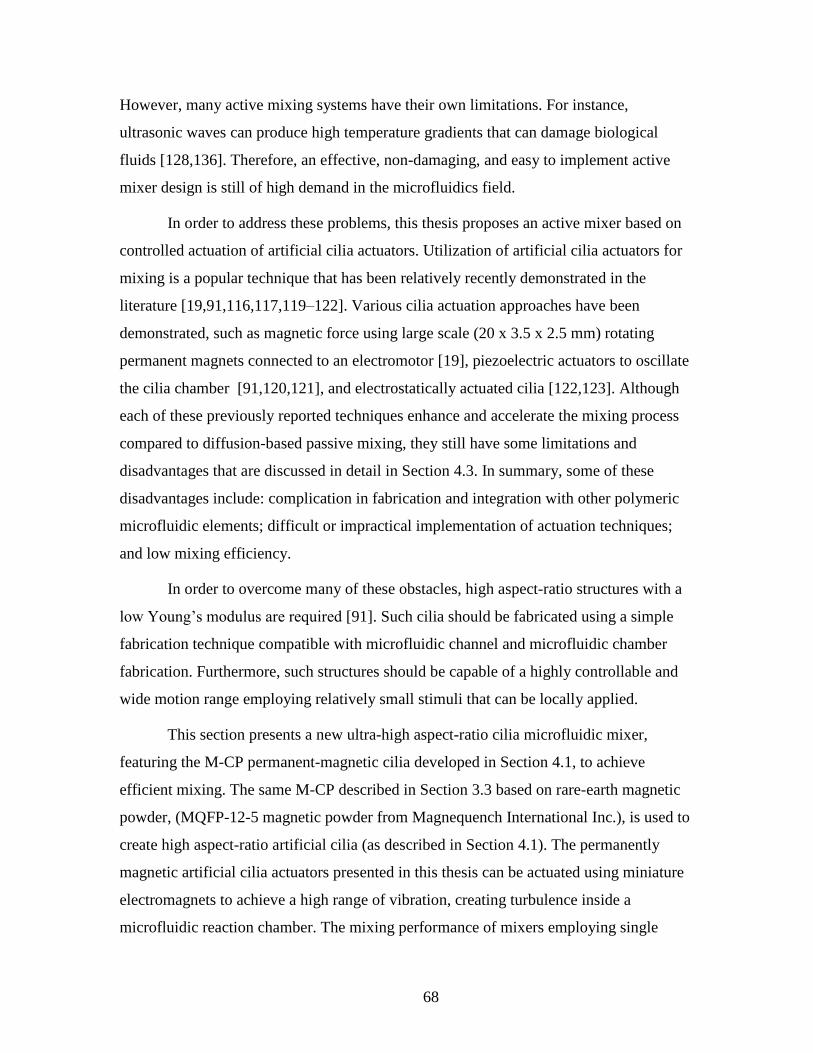
68
However, many active mixing systems have their own limitations. For instance,
ultrasonic waves can produce high temperature gradients that can damage biological
fluids [128,136]. Therefore, an effective, non-damaging, and easy to implement active
mixer design is still of high demand in the microfluidics field.
In order to address these problems, this thesis proposes an active mixer based on
controlled actuation of artificial cilia actuators. Utilization of artificial cilia actuators for
mixing is a popular technique that has been relatively recently demonstrated in the
literature [19,91,116,117,119–122]. Various cilia actuation approaches have been
demonstrated, such as magnetic force using large scale (20 x 3.5 x 2.5 mm) rotating
permanent magnets connected to an electromotor [19], piezoelectric actuators to oscillate
the cilia chamber [91,120,121], and electrostatically actuated cilia [122,123]. Although
each of these previously reported techniques enhance and accelerate the mixing process
compared to diffusion-based passive mixing, they still have some limitations and
disadvantages that are discussed in detail in Section 4.3. In summary, some of these
disadvantages include: complication in fabrication and integration with other polymeric
microfluidic elements; difficult or impractical implementation of actuation techniques;
and low mixing efficiency.
In order to overcome many of these obstacles, high aspect-ratio structures with a
low Young’s modulus are required [91]. Such cilia should be fabricated using a simple
fabrication technique compatible with microfluidic channel and microfluidic chamber
fabrication. Furthermore, such structures should be capable of a highly controllable and
wide motion range employing relatively small stimuli that can be locally applied.
This section presents a new ultra-high aspect-ratio cilia microfluidic mixer,
featuring the M-CP permanent-magnetic cilia developed in Section 4.1, to achieve
efficient mixing. The same M-CP described in Section 3.3 based on rare-earth magnetic
powder, (MQFP-12-5 magnetic powder from Magnequench International Inc.), is used to
create high aspect-ratio artificial cilia (as described in Section 4.1). The permanently
magnetic artificial cilia actuators presented in this thesis can be actuated using miniature
electromagnets to achieve a high range of vibration, creating turbulence inside a
microfluidic reaction chamber. The mixing performance of mixers employing single

69
cilium and arrays of multiple cilia are characterized and the results are presented in
Section 4.2.3. Approximately 85% of the total volume is fully mixed after 3.5 minutes
using a single cilium mixer compared with only 20% of the total volume mixed with
passive diffusion; this mixing performance is very promising for our intended purposes
for µTAS and LOC applications such as reagent mixing for polymerase chain reaction
(PCR), e.g., as part of the µROAMS project.
4.2.2 Experimental Setup
For characterization testing of the cilium, several demonstration devices are
fabricated with cilium of different lengths. While the longer cilia structures are not used
for mixing, they allow examination of the relationship between cilium length and
maximum tip displacement, as well as studies on the effect of magnetization on the
performance of the cilia mixer.
Cilia microstructures with a height of 1.5 mm are fabricated in the bottom of
reaction chambers. The reaction chambers have a diameter of 4 mm and a height of 1.7
mm, large enough to hold approximately 21 µL of fluid.
Figure 38: Testing reaction chamber used to capture cilia mixer performance. (The
reaction chamber has a diameter = 4 ± 0.5 mm, and a height = 1.7 ± 0.5 mm. Cilium
diameter = 130 ± 5 µm, and cilium height = 1.5 ± 0.01 mm).
Miniature electromagnets (tubular electromagnets from Magnetic Sensor Systems
series E-66-38) providing relatively small magnetic fields up to 7 mT at the base of the
cilia are used to locally actuate the cilia mixers (Figure 39). Figure 40 shows a 2 mm long
cilium with a diameter of 130 ± 5 µm actuated in a 7 mT magnetic field at 60 Hz created

70
by the electromagnet. A long exposure is used while taking the image in order to show
the vibration range in a single image.
Figure 39: Miniature electromagnet used for cilia actuation (outer cylinder: diameter =
9.6 mm, height = 16.7 mm).
Figure 40: Cilium structure range of motion, R, actuated using a 7 mT miniature
electromagnet at 60 Hz (cilium diameter = 130 ± 5 µm, cilium length = 2 mm).
For the cilia actuation, the miniature electromagnet is directly located under the
mixing chamber and touches the bottom of the chamber (Figure 41 and Figure 42).

71
Figure 41: A cilium located on top of a miniature electromagnet and actuated using a 7
mT magnetic field at 60 Hz. This cilium is fabricated on a flat piece of PDMS (cilium
diameter = 130 ± 5 µm, cilium length = 1.5 mm).
Figure 42: Illustration of the cross-sectional view of the configuration of a mixing
chamber and electromagnet employed for testing. This diagram is for illustration purpose
and is not to scale.
To determine the effects of the cilium’s vibration range and vibration frequency
on the mixing performance of the cilia mixer, the electromagnet is powered by a signal
generator that provides square waves with adjustable frequency and amplitude. The
electromagnet is first excited at frequencies ranging from DC to 120 Hz at constant
amplitude of 20 V. To test the effect of different actuation amplitudes on mixing
performance, the electromagnets are powered with different voltages ranging from 0 to
20 V at the natural frequency of the 1.5 mm tall cilium, 60 Hz. A microscope mounted
CCD camera is used to capture videos that are later converted into image sequences,
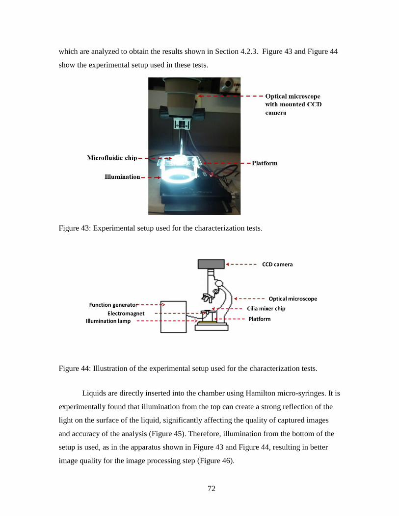
72
which are analyzed to obtain the results shown in Section 4.2.3. Figure 43 and Figure 44
show the experimental setup used in these tests.
Figure 43: Experimental setup used for the characterization tests.
Figure 44: Illustration of the experimental setup used for the characterization tests.
Liquids are directly inserted into the chamber using Hamilton micro-syringes. It is
experimentally found that illumination from the top can create a strong reflection of the
light on the surface of the liquid, significantly affecting the quality of captured images
and accuracy of the analysis (Figure 45). Therefore, illumination from the bottom of the
setup is used, as in the apparatus shown in Figure 43 and Figure 44, resulting in better
image quality for the image processing step (Figure 46).

73
Figure 45: Reaction chamber illuminated from top with strong light reflection from the
top surface of the blue liquid inside the reaction chamber, which interferes with the
accuracy of the image processing step.
Figure 46: Reaction chamber illuminated from bottom as shown in Figure 43 with no
light reflection from the top surface of the liquid.
Initial testing using 0.2 µL of a single color dye added to 20 µL of deionized (DI)-
water and mixed using the cilia mixer finds that a single color does not provide enough
color density change from the beginning to the end of the mixing process to provide clear
results of degree of mixing for image processing steps (Figure 47). To improve the
accuracy of image processing, mixing of liquids with two distinct die colors, red and
green, is used instead. A volume of 0.1 µL of red and 0.1 µL of green dyes are mixed
with 20 µL of DI-water to allow for clear image analysis of the mixing process (Figure
48).

74
Figure 47: Single color dye mixed with DI-water. It does not provide enough color
change between un-mixed, initial stage, and mixed, final stage, for accurate image
analysis.
Figure 48: Multiple color dyes mixed with DI-water. This technique is used for mixer
performance characterization testing. It provides enough clear color change between un-
mixed, initial stage, and mixed, final stage, for accurate image analysis.
4.2.3 Experimental results
To determine the effect of permanent magnetization of the M-CP cilia on the
mixer’s performance, 2 mm long cilia actuators are actuated under different magnetic
field configurations and the cilia tip displacement are recorded before and after
magnetization. As shown in Table 6, cilia tips showed much higher displacement after
being magnetized in a 1.8 ± 0.2 Tesla magnetic field, provided by the custom-made
permanent magnet by Dexter Magnetic Technologies, shown in Figure 22. Furthermore,
actuation fields as low as 1.1 mT actuate the cilium by a substantial amount (115 µm).

75
Table 6: Relationship between applied electromagnet voltages, generated magnetic field,
and maximum cilium tip displacement before and after magnetization of the cilium,
(cilium diameter = 130 ± 5 µm, cilium height = 2 ± 0.01 mm, magnetization field = 1.8 ±
0.2 T).
Actuation
Voltage (V)
Magnetic
field
(mT)
Average cilium tip
displacement for
permanently
magnetized
M-CP cilium
(µm)
Average cilium tip
displacement for
non-magnetized M-
CP cilium
(µm)
2 1.1 115 ± 2 0
4 2.7 195 ± 2 0
6 4.1 350 ± 2 5 ± 2
8 5.6 480 ± 2 5 ± 2
10 7.0 600 ± 2 8 ± 2
Figure 49 shows an array of three cilia structures (cilia height = 2 mm) actuated
under a 7 mT magnetic field before (left) and after (right) permanent magnetization in 1.8
± 0.2T magnetic field. As suggested by Table 6, there is almost no significant actuation
before the permanent magnetization of the M-CP cilia.
Figure 49: Range of motion for an array of three cilia actuated in 7 mT magnetic field
before magnetization (left) and after magnetization (right) in 1.8 ± 0.2 T magnetic field
(cilium diameter = 130 ± 5 µm, cilium = 2 ± 0.01 mm, magnetization field = 1.8 ± 0.2 T,
actuation field = 7 mT).

76
To characterize the performance and efficiency of permanently magnetized cilia
mixers, two complete sets of characterization experiments are carried out. The first set of
characterization tests are designed to find the effects of different cilia lengths, vibration
frequencies, and vibration amplitudes on mixing performance of a single cilium
microstructure. For these tests, a single cilium is fabricated at the center of a reaction
chamber. In the second set of tests, the effect of increasing the number of cilia structures
per same chamber volume is studied by creating arrays of multiple cilia. In all of these
tests, miniature electromagnets (tubular electromagnets from Magnetic Sensor Systems
series E-66-38) are used to locally actuate the cilia (Figure 39).
All of these characterization test results are obtained using two-dimensional
microscopy images due to the limitation of available imaging equipment. As a result, the
efficiency of mixing in vertical direction is not fully analyzed. This aspect of the mixing
performance will be explored in future work.
To find the effects of a cilium’s length and the excitation magnetic field strength
on a mixer’s performance, cilia structures with a diameter of 130 ± 5 µm and heights
ranging from 500 µm to 2.8 mm are actuated in electromagnetic fields ranging from 1.1
mT to 7 mT. Miniature electromagnets, such as that shown in Figure 39, are used to
actuate the cilia. Table 9 shows the relationship between voltages applied to the
electromagnets, generated magnetic field as measured by an F.W.Bell®
Hall effect
Gauss/Tesla meter model 5180, and resulting cilium displacement for different cilium
lengths. This data shows that, for a fixed magnetic field and frequency, the taller a cilium
structures is, the larger the cilium vibration amplitude and hence the better its mixing
performance should be. Therefore, for a given size reaction chamber, it is best to have the
tallest possible cilium mixer that can be fit into the chamber and can freely vibrate
without touching the top surface.
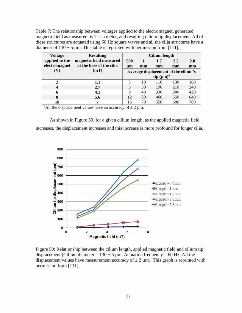
77
Table 7: The relationship between voltages applied to the electromagnet, generated
magnetic field as measured by Tesla meter, and resulting cilium tip displacement. All of
these structures are actuated using 60 Hz square waves and all the cilia structures have a
diameter of 130 ± 5 µm. This table is reprinted with permission from [111].
Voltage
applied to the
electromagnet
(V)
Resulting magnetic field measured
at the base of the cilia
(mT)
Cilium length
500
µm 1
mm 1.7
mm 2.2
mm 2.8
mm
Average displacement of the cilium’s
tip (µm)a
2 1.1 5 10 110 130 160 4 2.7 5 30 190 210 240 6 4.1 9 40 330 380 420 8 5.6 12 60 460 550 640 10 7 16 70 550 680 780
aAll the displacement values have an accuracy of ± 2 µm.
As shown in Figure 50, for a given cilium length, as the applied magnetic field
increases, the displacement increases and this increase is more profound for longer cilia.
Figure 50: Relationship between the cilium length, applied magnetic field and cilium tip
displacement (Cilium diameter = 130 ± 5 µm. Actuation frequency = 60 Hz. All the
displacement values have measurement accuracy of ± 2 µm). This graph is reprinted with
permission from [111].

78
Figure 51 shows the mixing efficiency of a single cilium mixer at various
excitation frequencies and actuated under a 7 mT magnetic field. This device uses 1.5
mm long cilium, and is fully assembled for mixing liquids. Actuation at 0 Hz,
corresponding to passive mixing by natural diffusion, results in very little mixing
occurring inside the chamber: less than 20% of the chamber’s total volume is partially
mixed after 15 minutes using natural diffusion mixing alone (Figure 52-(c) and (d)).
However, when active mixing (10 – 120 Hz) is used, more than 85% of the volume is
fully mixed after approximately 3.5 minutes and almost 98% mixing is achieved after
about 10 minutes. At 15 minutes approximately 100% mixing is achieved by utilizing a
single cilium mixer (Figure 50-(a) and (b)). Table 8 shows that the cilium mixer reduces
mixing time to achieve 20% of the total volume mixed by more than 16 times compared
to passive diffusion (Figure 51).
Figure 51: Experimental cilium mixing results showing percentage mixed over elapsed
time for different actuation frequencies at 7 mT. 0 Hz is no actuation (diffusion only)
(cilium length = 1.5 ± 0.01 mm, cilium diameter = 130 ± 5 µm). This graph is reprinted
with permission from [111].

79
Figure 52: Sample images of the mixing process compared to diffusion alone. (a) and (b)
show 60 Hz actuation of the cilium at times t = 0 min and t = 15 min, respectively. (c)
and (d) show natural diffusion at times t = 0 min and t = 15 min, respectively, with no
cilium actuation. This image is reprinted with permission from [111].
Table 8: Mixing efficiency of a single cilium mixer compared to natural diffusion. This
data is reprinted with permission from [111].
Mixing method Approximate time to reach 20% of the total
volume mixed (s)
Natural diffusion (0 Hz) 800
Cilium mixing (10 – 120 Hz) 50
Figure 53 shows the effect of different applied excitation magnetic field strengths
on the mixing performance of a cilium microstructure at 60 Hz. As the magnetic field
increases, the mixing performance of the cilium improves due to the increase in the
cilium vibration range resulting from the higher applied magnetic field. Figure 51 and
Figure 53 also show that increasing the strength of the excitation magnetic field, and
hence the vibration amplitude of the cilium, has a more profound effect on mixing
performance than increasing the frequency.
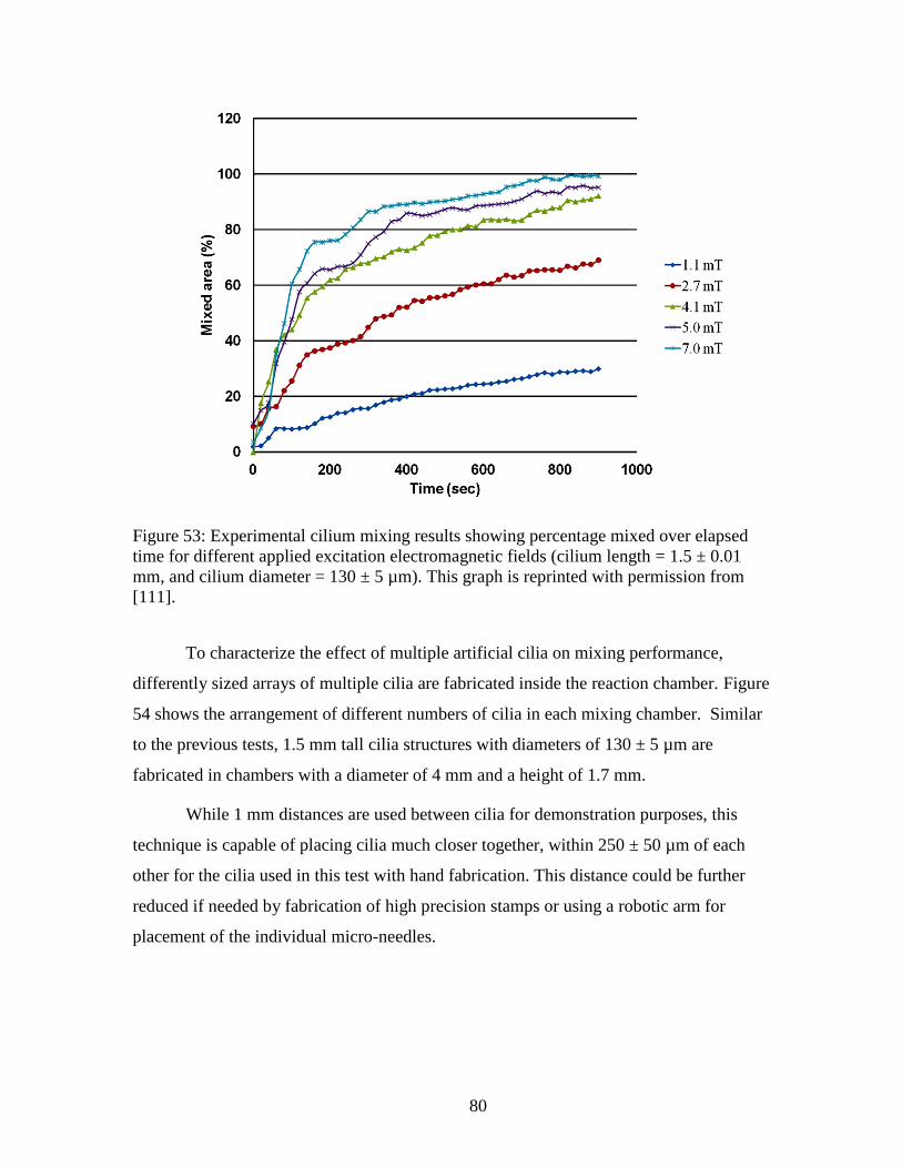
80
Figure 53: Experimental cilium mixing results showing percentage mixed over elapsed
time for different applied excitation electromagnetic fields (cilium length = 1.5 ± 0.01
mm, and cilium diameter = 130 ± 5 µm). This graph is reprinted with permission from
[111].
To characterize the effect of multiple artificial cilia on mixing performance,
differently sized arrays of multiple cilia are fabricated inside the reaction chamber. Figure
54 shows the arrangement of different numbers of cilia in each mixing chamber. Similar
to the previous tests, 1.5 mm tall cilia structures with diameters of 130 ± 5 µm are
fabricated in chambers with a diameter of 4 mm and a height of 1.7 mm.
While 1 mm distances are used between cilia for demonstration purposes, this
technique is capable of placing cilia much closer together, within 250 ± 50 µm of each
other for the cilia used in this test with hand fabrication. This distance could be further
reduced if needed by fabrication of high precision stamps or using a robotic arm for
placement of the individual micro-needles.

81
Figure 54: Cilia arrangement in the mixing chamber for multiple cilia mixers. The
illustrations on the right side are from a viewpoint looking down into the chamber and
showing the placement of the multiple free-standing vertical cilia. The distance between
each two adjacent cilium is approximately 1mm. This diagram is for illustration purpose
and is not to scale.
The fabrication technique for these devices is the same as the procedure explained
in Figure 18; the only difference is that, in this case, multiple micro-needles must be
inserted in different locations inside the chamber. For the results presented in this thesis,
the micro-needles are inserted by hand and individually. However, for high throughput
and large scale fabrication, customized stamps could be created and controlled by robotic
arm for higher placement precision and faster micro-fabrication processing (Figure 21).
It is found experimentally that, for cilia taller than 1 mm and gap sizes between
the cilia below 500 ± 50 µm, attraction between the highly magnetized M-CP cilia
structures causes them to start to bend towards each other due to magnetic attraction, and
sometimes collapse into one another. For 0.5 mm tall cilia, the distance between cilia can
be decreased to around 200 µm. The probability of collapses increases as the cilium
height increases, due to the reduction in structural rigidity as the cilia are lengthened.
While magnetizing the cilia limits the spacing as compared to non-magnetized
cilia, this approach offers two distinct advantages. First, the addition of permanently
magnetic particles to the cilia allows for bi-directional actuation. Non-magnetized cilia
only attract to the actuation field, while magnetized cilia alternatively attract and repel.
This results in actuation with greater displacement. Second, compared to previous designs
that were doped with weakly magnetic particles (e.g. Fe-based), the proposed design
using highly-magnetic rare-earth particles exhibiting much higher displacement for the
same actuation magnetic field. Furthermore, with ultra-high aspect-ratio structures, such

82
as cilia, spatial densities beyond this may result in physical interactions between the
vibrating cilia, putting another physical limitation on the displacement. The high aspect-
ratio and highly flexible cilia design presented in this thesis maximizes the displacement
of the cilia, which has the most significant impact on the effectiveness of the mixer as
shown in Figure 53.
As shown in Figure 55, increasing the number of cilia in a chamber increases the
mixing efficiency significantly, with 8 cilia mixing approximately twice the volume as 4
cilia after the same time period of 1 minute with the same magnetic field strength (7 mT)
and frequency (60 Hz).
Figure 55: Mixer performance for different number of cilia microstructures per chamber
after one minute of mixing at 60 Hz and applied magnetic field of 7 mT. This graph is
reprinted with permission from [111].
4.3 Comparison with the Prior Art
Fabrication of successful cilia structures for mixing purposes has been previously
reported by other researchers [19,91,106,116,117,119,120,122]. However, in most cases,
there were factors that significantly limited the practicality or the performance of the
previously demonstrated cilia actuators in LOC and µTAS applications. In this section,
some of these limitations are described and it is shown how the new designs

83
demonstrated in this thesis may eliminate or reduce the impact of some of these
limitations on fabrication and/or performance of cilia-based microfluidic mixers.
The most direct comparison between the cilia structures presented in this thesis
and other cilia mixer elements presented in the literature may be made with the mixer
cilia of Riahi et al. [19] and Liu et al. [106] , since the geometrical design and structural
resemblance between them and the cilia actuator proposed in this thesis are the closest. In
[19], Riahi et al. uses a CO2 laser machine to make cone shape holes on PMMA, which
are then used as cilia molds. The holes are first filled with ferromagnetic iron (Fe) micro-
particles and then covered with PDMS to form Fe-doped cones which are then placed in
PMMA microfluidic channels to act as individual mixer elements. In order to directly
compare the mechanical characteristic of the cone shaped structures suggested by [19]
with the cylindrical structures suggested in the this thesis, similar structures using the
same method suggested by Riahi at al. are fabricated and compared to the cilia actuators
made using the technique suggested in this thesis. A Universal Laser System’s
VersalLASER©
Laser ablation system is used to pattern the PMMA mold. The holes are
then filled with (Nd0.7Ce0.3)10.5Fe83.9B5.6 magnetic particles, a material with much higher
magnetization than the weakly magnetic Fe-doped polymer [24] suggested by Riahi et al.
[19]. Channels and holes fabricated using the CO2 laser cutter exhibit a Gaussian profile
(Figure 56). Using these structures as the master mold for fabrication of PDMS cilia
results in cone shaped pillars (Figure 57(a)). It proves very difficult to precisely control
the diameter and the depth of the holes. The cone shape structures have significantly
lower flexibility when compared to uniform cross-sectional cylindrical shaped cilia made
using the new fabrication technique presented in this thesis (Figure 57(b)). Figure 57
shows two cilia structures with almost the same height realized using the two different
fabrication techniques. The structure made using a laser cutter results in an aspect-ratio of
2:0.7. The structure made using the technique described in this thesis has an aspect-ratio
of 2:0.13. In Figure 57, both structures are actuated using a 110 mT permanent magnet. It
is clear that, while both of the cilia are made of PDMS and doped with the same rare-
earth magnetic powder, the cylindrical cilium shows a very high degree of deflection
whereas there is much less deflection for the cilium made using the laser cutter-based
molds.

84
Figure 56: Cross-section of a microfluidic channel created using Universal Laser
System’s VersalLASER©
Laser ablation system CO2 laser. This image is reprinted with
permission from [111].
Figure 57: Cilia structures fabricated from the same material using two different
techniques. (a) Using a mold made by patterning commercial poly(methyl methacrylate),
PMMA, using a CO2 laser cutter (height = 2 ± 0.5 mm), similarly to [9] except employing
highly magnetic rare-earth materials and (b) using the new fabrication technique
described in this work (height = 1.8 ± 0.01 mm). Both of these structures are actuated
using a 110 mT permanent magnet, showing higher flexibility for cilia fabricated using
the new fabrication technique presented in this thesis. This image is reprinted with
permission from [111].
As a result of the low magnetization of the Fe-doped polymer and the reduced
flexibility due to the cone shape of the cilium, Riahi et al. need to put a large permanent
magnet (length = 20 mm, width = 3.5 mm and height = 2.5 mm) providing 75 mT next to
the cilia in order to deflect the beam sufficiently (illustrated in Figure 58(b)). A large-
scale magnet connected to an electromotor next to each mixer microstructure adds
considerable complexity to the packaging of the microfluidic chip, and is impractical for
complicated microfluidic systems with multiple chambers and mixers such as that

85
required for, e.g., the µROAMS project. On the other hand, using the technique proposed
in this thesis, sufficient deflection can be achieved using miniature electromagnets
providing only 7 mT. Each electromagnet can be located underneath or above the
chamber, (illustrated in Figure 58(a)), which is far more manageable for large scale or
complex multi-chamber/multi-mixer microfluidic chip designs.
Other prior results are also not as effective as the solution presented in this thesis.
For example, Liu et al. [106] present Fe-doped artificial cilia fabricated using a modified
3D printer system. Although using this technique results in fabrication of filaments with
high aspect-ratio and vertical side walls, it still suffers from some major limitation.
Similarly to the structure fabricated by Riahi et al. the structures fabricated using the Liu
et al. technique employ Fe-doped composite polymer which results in much lower
magnetization level than the rare-earth M-CP presented in this thesis. Also, bi-directional
actuation is not possible in both cases of [20] and [106] due to the use of soft-magnetic
materials. In addition, the composite polymer used by Liu et al. [106] can be only doped
up to 40% w/w with iron particles because a 40% doping level is the maximum
percentage to be extruded without blocking the tip of the printer. This relatively low
achievable doping level, compared to 80% doping level with rare-earth magnetic powder
used in this thesis, reduces the actuation efficiency even further. As a result, a relatively
large permanent magnet (diameter = 25 mm, and thickness = 5 mm) providing 245 mT
magnetic field mounted on a moving linear stage must be used for the cilia actuation
(illustrated in Figure 58(c)). Another significant limitation of the fabrication technique
proposed by Liu et al. is that their fabrication technique employs a long filament structure
that is printed on a glass slide. After the polymer is cured, the filament is manually cut
into the desired sizes and the fragments are manually mounted on the desired surface.
Although the paper does not explain the details involved in the mounting of individual
cilia fibers on their desired locations, fixing individual small cilia-like structures one by
one on a surface is expected to be a highly labor-intensive process that does not scale
well for high volume production. This limitation becomes even more significant as the
number of cilia structures required for a device increases.

86
Figure 58: (a) M-CP cilia structure and actuation mechanism fabricated in this thesis. (b)
Fe-doped cilia structure and actuation mechanism suggested by Riahi et al. [19], and (c)
Fe-doped cilia structure and actuation mechanism suggested by Liu et al. [106]. Both of
the rotating magnet used by Riahi et al. and the moving magnet used by Liu et al. need to
be orders of magnitude stronger than the electromagnet used in this thesis due to the use
of weakly magnetic Fe-doped polymers. The doping level of Fe powder in PDMS used
by Liu et al. is limited to a maximum of 40% w/w as opposed to 80% rare-earth magnetic
powder in PDMS used in this thesis. The cone shape of the structure proposed by Riahi et
al. significantly reduces the flexibility of the cilia structure. Both of the structures
suggested by Riahi et al. and Liu et al. are not capable of providing bi-directional
actuation since Fe doped polymers are only capable of providing attraction force. As a
result the achievable vibration range in both cases is at most half of that of the cilia
structure suggested in this thesis.
87
In other research, Timonen et al. [117] presented flexible magnetic artificial cilia
based on spontaneous surface deformation of ferrofluids in the presence of a magnetic
field. Cobalt particles are mixed with toluene and an elastomeric polymer. In the presence
of the magnetic field, the cobalt particles form conical structures. While still under an
applied magnetic field, the toluene is allowed to evaporate and the polymer solidifies.
The length and the aspect-ratio of the cilia structures depends strongly on the vertical
magnetic field gradient applied during the cilia formation. Aspect-ratios of 20 and 120
are achieved under 0.1 T/m and 20 T/m vertical gradients, respectively. Their presented
technique has many positive aspects, such as mechanically stable structures and ease of
fabrication. However, there are some disadvantages. For example, actuation requires
fairly high magnetic fields of 450 mT. The most major shortcoming of the Timonen et al.
fabrication technique is that it is relatively hard to precisely control the density, length,
diameter and thickness of the cilia fibers. As the technique suggested by Timonen et al.
resulted in a high density of imprecisely placed cilia, the cilia could potentially act as
particle traps. Hence, the structures reported by Timonen et al. may not be suitable for
use as a mixer for liquids that contain particulates or biological entities of sufficient size
to become trapped. The fabrication technique presented in this thesis, in contrast, results
in consistent dimension of each individual cilium and precise positioning within the
microfluidic device. As previously discussed in Section 4.1, the length, height and
diameter of each cilium can also be individually determined and placed precisely.
Furthermore, Timonen et al. found that if the magnetic field is suddenly removed, their
cilia structures never completely relax back to a vertical position without applying a
vertical magnetic field to erect the cilia. For the design presented in this thesis, whenever
the magnetic field is removed, the cilia relax to their original well-controlled positions.
For example, in one experiment, it takes less than 0.5 seconds for the cilia structures to
relax back to their original vertical position after removal of the magnetic field. Similarly
to the work by Riahi et al. [19] and Liu et al. [106] discussed previously, Timonen et. al.
[117] also do not discuss the performance of their artificial cilia structure as microfluidic
mixers employing their cilia. Thus, it is not possible to compare the mixing performance
of the mixers presented in this thesis with any of those proposed in [19], [106] or [117].

88
The cilia structures demonstrated by Toonder et al. [90,116,123] are based on
electrostatically actuated polymer structures. The Toonder et al. cilia structures are curled
microbeams consisting of a double layer of a thin polymer film, polyimide, and a thin
conductive chromium layer. The cilia has a length of 100 µm and a width of 20 µm, and
are actuated by applying a voltage difference between the indium tin oxide electrode and
the Cr layer (Figure 59).
Figure 59: Cross-sectional view of the cilia structure reported in [116]. This image is
reprinted with permission from [111].
Because of the relatively small size of their structures, the structures presented by
Toonder et al. may be advantageous over the design presented in this thesis for
microfluidic systems that require microfluidic channels with very small sizes (e.g., < 100
micrometers). However, the Toonder et al. mixer suffer from problems of fabrication
complexity and durability. As reported in [116], the Toonder et al. mixers show signs of
failure after switching cycles at 1 Hz [116]. In addition, the mixers demonstrated
by Toonder et al. require a relatively complicated multilayer fabrication process with
access to expensive microfabrication equipment, such as a sputtering machine and plasma
enhanced chemical vapor deposition (PECVD). The relatively complex fabrication
techniques are a limiting factor for rapid prototyping applications where low fabrication
cost is required. In contrast, the fabrication technique described in this thesis is simple
and of relatively low cost. Furthermore, cilia structures made using the PDMS-based
microfabrication technique described in this thesis are flexible and are not prone to
fracture due to mechanical stress or handling of the microfluidic chip. For example, there
was no sign of any failure or fatigue after running the M-CP cilia mixers for 168 hours
(one week) at 60 Hz either with or without liquid, which represents approximately

89
cycles. From a mixing performance point of view, the performance of an array
of cilia structures suggested by [116] is comparable with the performance of a single
cilium mixer suggested in this thesis. The single cilium mixer presented in this thesis
results in a mixing time per volume of liquid ( T90%mix / V) of 10 s/µL and this value
reduces to less than 2.7 s/µL for an array of 8 cilia. This is similar to T 90%mix / V ranging
from 10 - 1 s/µL reported by Toonder et al. [116].
Oh et al. [91,121] have presented a mixer that consists of PDMS cilia structures
actuated by the vibration of an off-the-shelf lead-zirconate-titanate (PZT) piezoelectric
stage. Cilia structures as tall as 400 µm are fabricated using a novel underwater
fabrication technique. The cilia structures are also fabricated separately and then
assembled horizontally inside the chambers, which required additional assembly steps.
As all cilia must be actuated at once by the piezoelectric stage used for cilia excitation,
the mixers described by Oh et al. are limited in that multiple microfluidic mixers on the
same chip cannot be individually controlled, and all mixing chamber must be actuated at
once with the same parameters. The technique described by Oh et al. is particularly
limiting if there is a need to have independent control over individual chambers’
excitation frequency and/or amplitude, or even whether fluid in each individual chamber
is being actively mixed or not. The actuation technique described by Oh et al. also
requires complicated packaging, especially as the number of mixing chambers and the
complexity of the design increases. In contrast, the fabrication process employed for the
microfluidic mixers in this thesis allows production of the cilia structures directly inside
the microfluidic system with no additional assembly steps. By using miniature
electromagnets for each microfluidic mixer, each mixing chamber can be controlled
individually. Comparison of the mixing performance of the new microfluidic mixer
structures suggested in this thesis and the mixer presented by Oh et al. is shown in
Table 9.

90
Table 9: Characteristic parameters of microfluidic mixers form Oh et al. [91,121] and the
present thesis. This data is reprinted with permission from [111].
Reference
Cilium
per
chamber
Vol.
(µL)
------Diffusion------ ------Cilia mixer-----
[T90%mix/V]diff/
[T90%mix/V]mix
Approx.
T90%mix (s)
T90%mix/
V (s/µL)
Approx.
T90%mix (s)
T90%mix/
V (s/µL)
Oh et al. 3 7 651 93 81 11.6 8
This thesis 3 20 2700 135 120 6 22.5
4.1 Summary and Conclusion
In this chapter, the design and fabrication of ultra-high aspect-ration artificial cilia
actuators are developed. A novel fabrication technique is presented for manufacturing
ultra-high aspect-ratio cilia structures directly inside microfluidic structures, such as
reaction chambers and microfluidic channels. A new microfluidic mixer based on the
high aspect-ratio artificial cilia actuator is designed and fabricated employing the novel
fabrication technique. Neither the use of the proposed M-CP materials for fabrication of
artificial cilia structures nor the use of PEG as the sacrificial mold for fabrication of any
micro-structures has been previously reported in the literature prior to this research work.
The cilia micro-structures fabricated using these new techniques are used to create
active microfluidic mixers. The cilia mixer is one of the highest performing cilia-based
microfluidic actuators designs reported in the literature, with the capability of extreme
aspect-ratios under a controlled fabrication process, providing far more design flexibility
than previously available artificial cilia-based actuators. The high flexibility of the cilia
structures and highly magnetic rare-earth composite polymer material provide greatly
enhanced actuation and mixing performance for the cilia-based mixer developed in this
research work. The mixing performance of these cilia mixers are characterized and
compared with passive diffusion mixing, as well as other microfluidic mixer designs
discussed in prior work. The experimental result presented in this chapter shows that a
single cilium structure reduces the 90 % mixing time per unit volume by about 22 times
compared to passive diffusion ([T90%mix/V]diff/[T90%mix/V]mix = 22.5). The performance of
the mixer while actuated under different frequencies and different magnetic fields is

91
evaluated. It is shown that the change in the actuation magnetic field has a more profound
effect on the mixing efficiency than the change in frequency. Increasing the amplitude of
the magnetic field results in an increase in the vibration range of the cilia and hence
increases the amount of fluid disturbance created enabling higher mixing efficiency. An
array of cilia structures, instead of a single cilium mixer, reduces this mixing time even
further. It is also shown that approximately 85 % mixing can be achieved in about 70
seconds by using an array of 8 cilia, as opposed to 3.5 minutes for single cilium mixer,
when both are actuated under the same 7 mT and 60 Hz frequency magnetic field. A
thorough comparison of the new cilia actuators with the prior art is also provided in this
chapter. As a result of both the high magnetic forces and high flexibility of the high
aspect-ratio cilia, the cilia actuator presented in this thesis can be effectively actuated
using very small and localized magnetic field of 7 mT (which can be provided by a
miniature electromagnet), as compared to higher actuation magnetic fields required in
previously existing work. Highly flexible material allows the use of a smaller, easier to
integrate electromagnet for actuation. In addition, the cilia actuators described in this
thesis are robust and not prone to fracture due to mechanical stress or extended usage. For
example, there was no sign of any failure or fatigue after running the M-CP cilia mixers
for cycles.
The novel fabrication technique proposed in this chapter that is based on the
sacrificial PEG mold is relatively easy as well as being low cost. It can be used for high
volume and large scale productions. The combination of effective fabrication, actuation
technique, and effective mixing performance of these cilia mixers make their design
attractive for integration with many complex microfluidic designs in LOC and TAS
devices.

92
4.2 Related Publications
The results of this work have been presented in details in the following peer reviewed
publications:
1. Rahbar, M., Shannon, L., and Gray, B. L., “Microfluidic active mixers
employing ultra-high aspect-ratio rare-earth magnetic nano-composite
polymer artificial cilia,” Journal of Micromechanics and Microengineering,
24, 025003, 2014. (Selected for the JMM highlights of the year 2014;
available at:
http://cms.iopscience.iop.org/alfresco/d/d/workspace/SpacesStore/805630a6-
9c01-11e4-afec-29411a5deefe/JMM-Highlights-2014.pdf?guest=true)
2. Rahbar, M., Tseng, H. Y., and Gray, B. L., “High-aspect ratio magnetic
nanocomposite polymer cilium,” Proc. SPIE MOEMS-MEMS: Microfluidics,
BioMEMS, and Medical Microsystem;, International Society for Optics and
Photonics, 89760D-89760D-9, 2014. (Awarded: “The Best Student Paper
Award” in the overall MOEMS-MEMS symposium; available at:
http://spie.org/about-spie/press-room/event-news-details/pw14-news/pw14-
awards-photo-gallery-)

93
Chapter 5 - Flap-based Magnetic Composite Polymer
Actuator3
Flap-based, or beam-type, actuators are fairly simple actuators, and have
widespread use in microfluidics and MEMS [18,22,24,107,139–143]. The simplicity and
applicability of flap-based (or “flap”) actuators is a major motivation for the development
of new flap-based actuators described in this chapter. Previously presented flap-based
actuators generally suffer from two main limitations: 1) many are limited in scope to
passive structures such as check valves, and are not capable of sophisticated actuation
control [141–143]; and 2) the majority are implemented primarily in rigid or semi-rigid
materials such as silicon, SU-8, and thin metal layers such as aluminum
[18,21,23,105,139,140]. While highly compatible with, e.g., silicon microfabrication
techniques, these materials have lower compliancy and flexibility than polymers in
general, and elastomers in particular, requiring higher actuation force compared to a
similar structure fabricated using more flexible materials.
The flap-based microfluidic actuator described in this chapter addresses both of
these problems by utilizing the highly flexible and compliant PDMS-based M-CP in the
design of the magnetic flap-based actuator with a high level of actuation control. More
rigid materials such as silicon, SU-8, etc., have lower compliancy and flexibility than
polymers such as elastomers. This is especially less desirable for devices such as
microfluidic valves where fluid-tight seals and a large-stroke actuation are required for
high performance. A rigid structure also requires higher actuation force compared to a
similar structure fabricated using a more flexible material. PDMS elastomers and PDMS-
based M-CPs, on the other hand, offer high flexibility as well as ease of fabrication and
relatively low cost, and are highly effective at providing fluid-tight seals.
This chapter thus describes the development of a microfluidic flap-based actuator
primarily for use in valves for the µROAMs project. However, the valves developed in
3 The material presented in this section is mainly based on the material previously published in
[126]. The reprinted parts are author-created, un-copyedited version of the article accepted for publication
in Journal of Micromechanics and Microengineering. IOP Publishing Ltd is not responsible for any errors
or omissions in this version of the manuscript or any version derived from it. The Version of Record is
available online at [10.1088/0960-1317/26/5/055012].
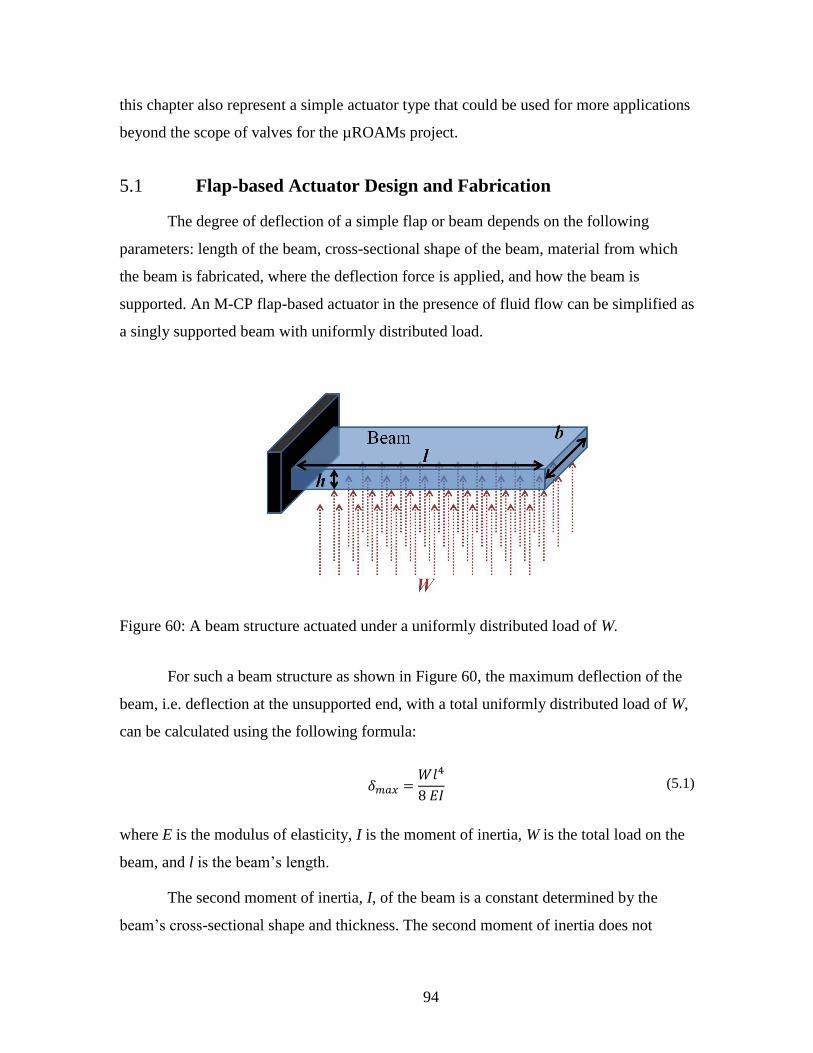
94
this chapter also represent a simple actuator type that could be used for more applications
beyond the scope of valves for the µROAMs project.
5.1 Flap-based Actuator Design and Fabrication
The degree of deflection of a simple flap or beam depends on the following
parameters: length of the beam, cross-sectional shape of the beam, material from which
the beam is fabricated, where the deflection force is applied, and how the beam is
supported. An M-CP flap-based actuator in the presence of fluid flow can be simplified as
a singly supported beam with uniformly distributed load.
Figure 60: A beam structure actuated under a uniformly distributed load of W.
For such a beam structure as shown in Figure 60, the maximum deflection of the
beam, i.e. deflection at the unsupported end, with a total uniformly distributed load of W,
can be calculated using the following formula:
(5.1)
where E is the modulus of elasticity, I is the moment of inertia, W is the total load on the
beam, and l is the beam’s length.
The second moment of inertia, I, of the beam is a constant determined by the
beam’s cross-sectional shape and thickness. The second moment of inertia does not
95
depend on the beam’s length or material. For a rectangular beam, the moment of inertia
can be calculated using the following formula:
(5.2)
where h is the dimension in the plane of bending and b is the width of the beam.
Therefore, as the thickness of the beam, h, increases, the moment of inertia of the
beam, I, increases. As a result, the maximum deflection of a thicker beam under the same
total load is lower when compared to a thinner beam.
The thickness of the flap is related to the M-CP material’s flux density according
to the following formulas. As it was earlier described in Section 3.3.1, the flux density for
cylindrical M-CP magnets at the surface of M-CP, z=0, can be estimated using the
following formula:
(5.3)
where D is the thickness of the M-CP and R is the diameter of the M-CP.
According to this formula the relationship between the magnetic flux density and
the thickness of the magnetic material is expected to be an exponential relationship.
Figure 61 shows the normalized graph that illustrates the relationship between the
magnetic flux density and the thickness of the M-CP cylinder.
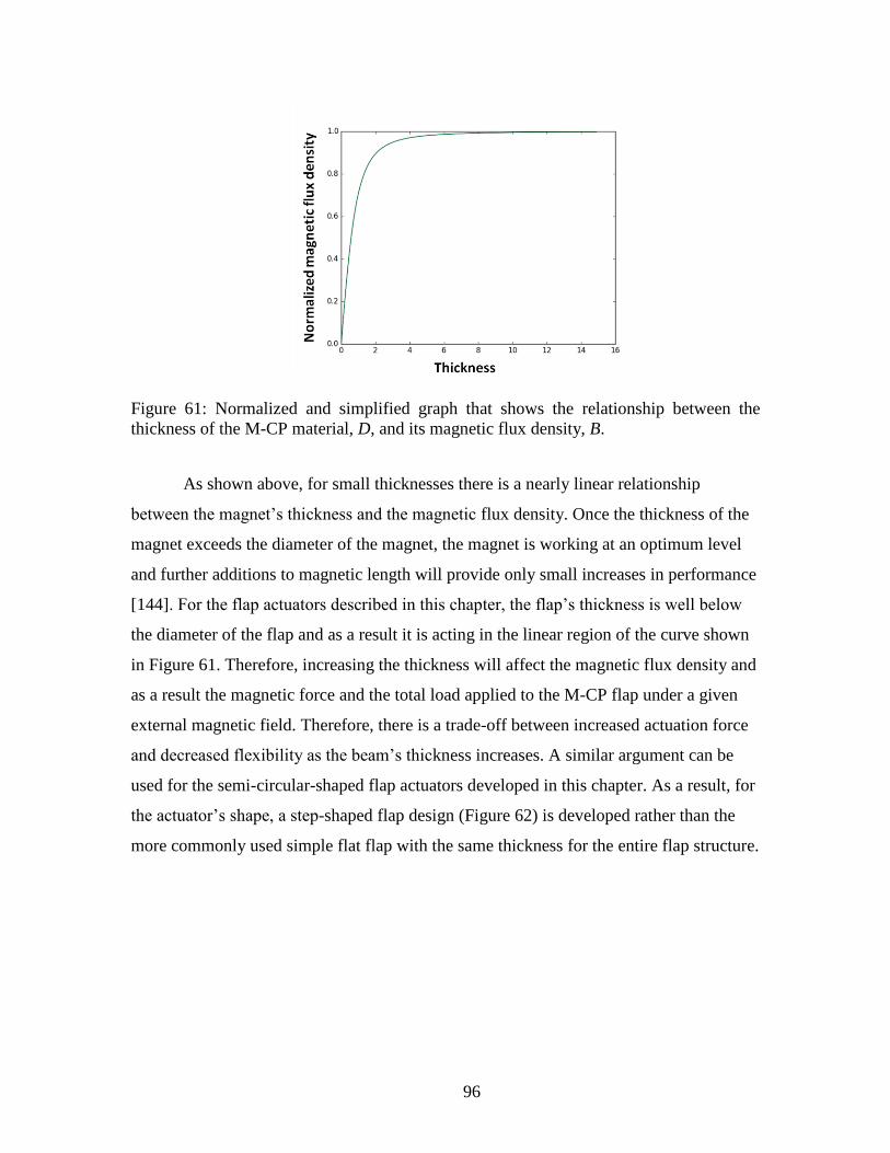
96
Figure 61: Normalized and simplified graph that shows the relationship between the
thickness of the M-CP material, D, and its magnetic flux density, B.
As shown above, for small thicknesses there is a nearly linear relationship
between the magnet’s thickness and the magnetic flux density. Once the thickness of the
magnet exceeds the diameter of the magnet, the magnet is working at an optimum level
and further additions to magnetic length will provide only small increases in performance
[144]. For the flap actuators described in this chapter, the flap’s thickness is well below
the diameter of the flap and as a result it is acting in the linear region of the curve shown
in Figure 61. Therefore, increasing the thickness will affect the magnetic flux density and
as a result the magnetic force and the total load applied to the M-CP flap under a given
external magnetic field. Therefore, there is a trade-off between increased actuation force
and decreased flexibility as the beam’s thickness increases. A similar argument can be
used for the semi-circular-shaped flap actuators developed in this chapter. As a result, for
the actuator’s shape, a step-shaped flap design (Figure 62) is developed rather than the
more commonly used simple flat flap with the same thickness for the entire flap structure.

97
Figure 62: Photograph of a step-shaped circular M-CP flap used for the valve fabrication
in this chapter.
As described above, the step-shaped design allows increased actuation force,
while maintaining the flexibility of the flap. Figure 63 shows a comparison between the
maximum deflections of a 2 mm thick flat beam and a 2 mm step-shaped flap-type
actuator actuated under an 80 mT magnetic field. As shown in this figure, no visible
deflection is achieved by using a flat flap. In contrast, large deflection is created by
employing a step-shaped flap design.
Figure 63: Comparison between the maximum deflections achievable by 2 mm thick
rectangular flaps: (a) shows a flat flap before applying the external actuation field, and (c)
shows the flat flap actuated under an 80 mT external magnetic field; (b) shows a step-
shaped flap before applying the external actuation field, and (d) shows the step-shaped
flap actuated under an 80 mT external magnetic field.
The step-shaped flap consists of two parts, the thicker segment of the flap and the
thinner segment of the flap. The following part of this section describes how each of
these two parts contributes to the improved performance of the step-shaped flap.

98
The thick segment of the step-shaped flap increases the actuation force under a
given magnetic field. To demonstrate the effect of increased thickness of the thick
segment of the step-shaped flap on the actuation force, samples of M-CP, 2 2 mm2 in
size with thicknesses ranging from 0.09 to 0.64 mm and made from M-CP, are mounted
on a scale and actuated under an 80 mT magnetic field. This field is provided by a
permanent magnet located 1 mm above the top surface of each M-CP sample. The change
in measured weight due to attraction force between the permanently magnetized M-CP
and the permanent magnet is measured and converted into the force applied to the M-CP.
An 80 mT actuation magnetic field is chosen, as it provides sufficient actuation force for
the flap-based microfluidic valve developed in this thesis to perform effectively in both
on/off and flow steering configurations, as is discussed in Section 5.2.1. Figure 11 from
Section 3.3.1 shows the relationship between the thickness of the M-CP material and the
magnetic actuation force.
The thin segment of the step-shaped flap design helps maintain flexibility of the
flap in the segment that experiences the maximum bending. Figure 64 demonstrates how
the thin segment of the step-shaped flap helps to effectively maintain the flap’s flexibility
compared to a single thickness flap with the same actuation field. As discussed in Section
5.2, when this step-shaped flap actuator is used in a microfluidic valve design, the highly
flexible and compliant flap with high actuation forces produces effective sealing in the
closed valve position, as well as large displacement in the open valve position.
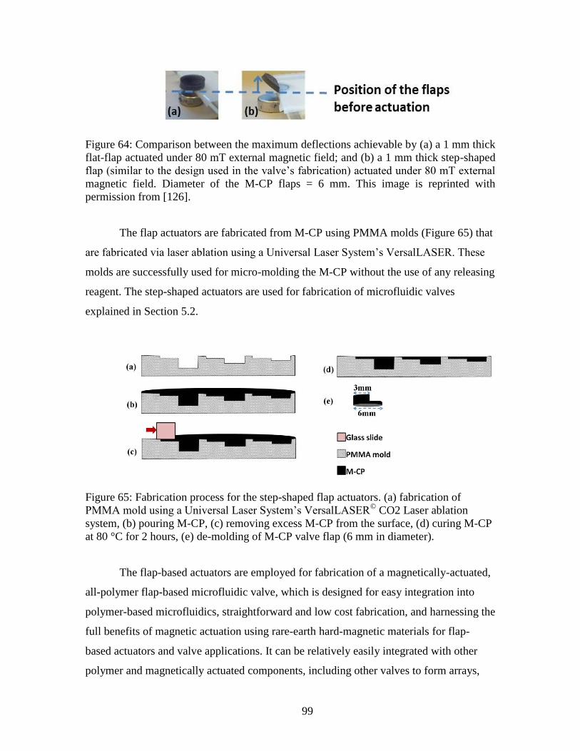
99
Figure 64: Comparison between the maximum deflections achievable by (a) a 1 mm thick
flat-flap actuated under 80 mT external magnetic field; and (b) a 1 mm thick step-shaped
flap (similar to the design used in the valve’s fabrication) actuated under 80 mT external
magnetic field. Diameter of the M-CP flaps = 6 mm. This image is reprinted with
permission from [126].
The flap actuators are fabricated from M-CP using PMMA molds (Figure 65) that
are fabricated via laser ablation using a Universal Laser System’s VersalLASER. These
molds are successfully used for micro-molding the M-CP without the use of any releasing
reagent. The step-shaped actuators are used for fabrication of microfluidic valves
explained in Section 5.2.
Figure 65: Fabrication process for the step-shaped flap actuators. (a) fabrication of
PMMA mold using a Universal Laser System’s VersalLASER©
CO2 Laser ablation
system, (b) pouring M-CP, (c) removing excess M-CP from the surface, (d) curing M-CP
at 80 °C for 2 hours, (e) de-molding of M-CP valve flap (6 mm in diameter).
The flap-based actuators are employed for fabrication of a magnetically-actuated,
all-polymer flap-based microfluidic valve, which is designed for easy integration into
polymer-based microfluidics, straightforward and low cost fabrication, and harnessing the
full benefits of magnetic actuation using rare-earth hard-magnetic materials for flap-
based actuators and valve applications. It can be relatively easily integrated with other
polymer and magnetically actuated components, including other valves to form arrays,
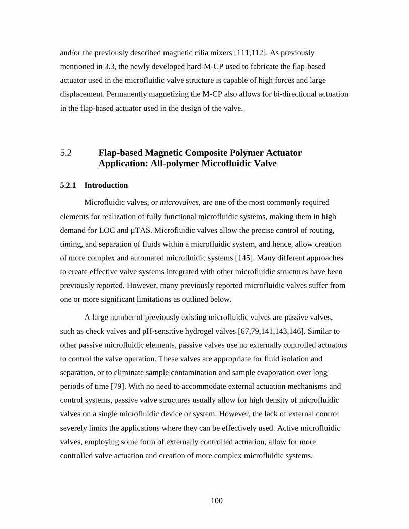
100
and/or the previously described magnetic cilia mixers [111,112]. As previously
mentioned in 3.3, the newly developed hard-M-CP used to fabricate the flap-based
actuator used in the microfluidic valve structure is capable of high forces and large
displacement. Permanently magnetizing the M-CP also allows for bi-directional actuation
in the flap-based actuator used in the design of the valve.
5.2 Flap-based Magnetic Composite Polymer Actuator
Application: All-polymer Microfluidic Valve
5.2.1 Introduction
Microfluidic valves, or microvalves, are one of the most commonly required
elements for realization of fully functional microfluidic systems, making them in high
demand for LOC and µTAS. Microfluidic valves allow the precise control of routing,
timing, and separation of fluids within a microfluidic system, and hence, allow creation
of more complex and automated microfluidic systems [145]. Many different approaches
to create effective valve systems integrated with other microfluidic structures have been
previously reported. However, many previously reported microfluidic valves suffer from
one or more significant limitations as outlined below.
A large number of previously existing microfluidic valves are passive valves,
such as check valves and pH-sensitive hydrogel valves [67,79,141,143,146]. Similar to
other passive microfluidic elements, passive valves use no externally controlled actuators
to control the valve operation. These valves are appropriate for fluid isolation and
separation, or to eliminate sample contamination and sample evaporation over long
periods of time [79]. With no need to accommodate external actuation mechanisms and
control systems, passive valve structures usually allow for high density of microfluidic
valves on a single microfluidic device or system. However, the lack of external control
severely limits the applications where they can be effectively used. Active microfluidic
valves, employing some form of externally controlled actuation, allow for more
controlled valve actuation and creation of more complex microfluidic systems.

101
As discussed in the introduction of this chapter, similar to many other elements of
microfluidic systems, many previously reported microfluidic valves are implemented
primarily in rigid or semi-rigid materials such as silicon, SU-8, and thin metal layers such
as aluminum [18,21,23,105,139,140] due to their reliance on fabrication techniques
derived from the semiconductor industry. These materials have lower compliancy and
flexibility than elastomers such as PDMS with a higher level of compliancy [12], and
thus require much higher actuation force compared to a similar structure fabricated using
more flexible materials. This makes them less desirable for microfluidic valves where
fluid-tight seals and a large-stroke actuation are required for high performance
[12,88,89]. This flexibility also results in lowered actuation forces for the microfluidic
valve, hence decreasing the size of the required actuation mechanism and allowing for a
higher density of valves on a device.
The actuation mechanism for a microfluidic valve is one of the most important
aspects of its design, and is the source of limitations associated with many of the
previously reported active microfluidic valves. Some of the more commonly employed
actuation techniques for microfluidic valves include: pneumatic [18,145,147–149],
thermo-pneumatic [150], piezoelectric [18,145,151,152], electrostatic [153], shape
memory alloy [18,145,154], and magnetic/electromagnetic [14–16]. As previously
discussed in Section 2.2.5, magnetic actuation offers distinct advantages for many
different microfluidic applications in general. The following are some of the distinct
advantages of magnetic actuation for microfluidic valves in particular as compared to
other actuation techniques commonly used for active microfluidic valves, such as
electrostatic, piezoelectric, pneumatic, and thermal actuators. Magnetic actuation is
advantageous for microfluidic valves as compared to electrostatic and piezoelectric
actuators in terms of strength, polarity, and distance of actuation [13]. Magnetic actuators
are also considerably more robust actuation mechanisms than electrostatic, thermal, and
piezoelectric actuators [22,85] which can be crucial in high performance valve
applications. Compared to pneumatic actuation techniques, some of the most commonly
used actuation mechanisms for microfluidic valves, magnetic actuation offers more
compact design and is more suitable for miniaturization and portable applications [76].
Compared to typically slow responding thermal actuation techniques, such as hydrogel

102
valves, magnetic valves offers rapid response time [57], which can also be a crucial
requirement in microfluidic valve application. However, despite the many advantages of
magnetic and electromagnetic actuation for microfluidic valve application, magnetically
actuated valves are still relatively less established than other actuation techniques such as
pneumatic valves. Further development of all-polymer magnetic valves could be highly
advantageous to the future of microfluidic systems [16].
The valve design and fabrication process are described in Section5.2.3. Section
4.2 discusses the experimentation and experimental results. Performance characterization
of a single valve as an on/off valve, as well as the effect of the permanently magnetized
M-CP valve seat on the valve’s performance and latching mechanism, are presented in
Section 5.2.5.1. Operation of multiple valves for flow steering is presented in Section
5.2.5.2. Section 5.2.5.3 provides details on the actuation mechanism optimization for the
microfluidic valve design. In Section 5.2.6, the structural design and performance of the
valve system presented in this thesis is compared with previous membrane- or flap-based
microfluidic valves presented in the literature. Finally, a conclusion is presented in
Section 5.3.
5.2.2 Material
The same M-CP described in Section 3.3 is employed for the fabrication of the
flap-based microfluidic valve presented in this section. As discussed in Section 3.3, this
highly magnetic, yet highly flexible and compliant polymeric material is capable of
providing strong bi-directional actuation at the micro-scale. It also provides both
attraction for closing the valve and repulsion for assisted opening of the valve.
Furthermore, the M-CP is employed for a permanently magnetized valve seat fabricated
in M-CP; to the author’s knowledge, this is the first reported use of a magnetic polymer
valve seat. The use of permanently magnetized M-CP for both the valve seat and the
valve flap ensures intimate contact between both structures and enhances the closing
performance. As a result, a relatively small magnetic field of 80 mT, created by a small
permanent magnet, is used for valve actuation. This compares to relatively larger
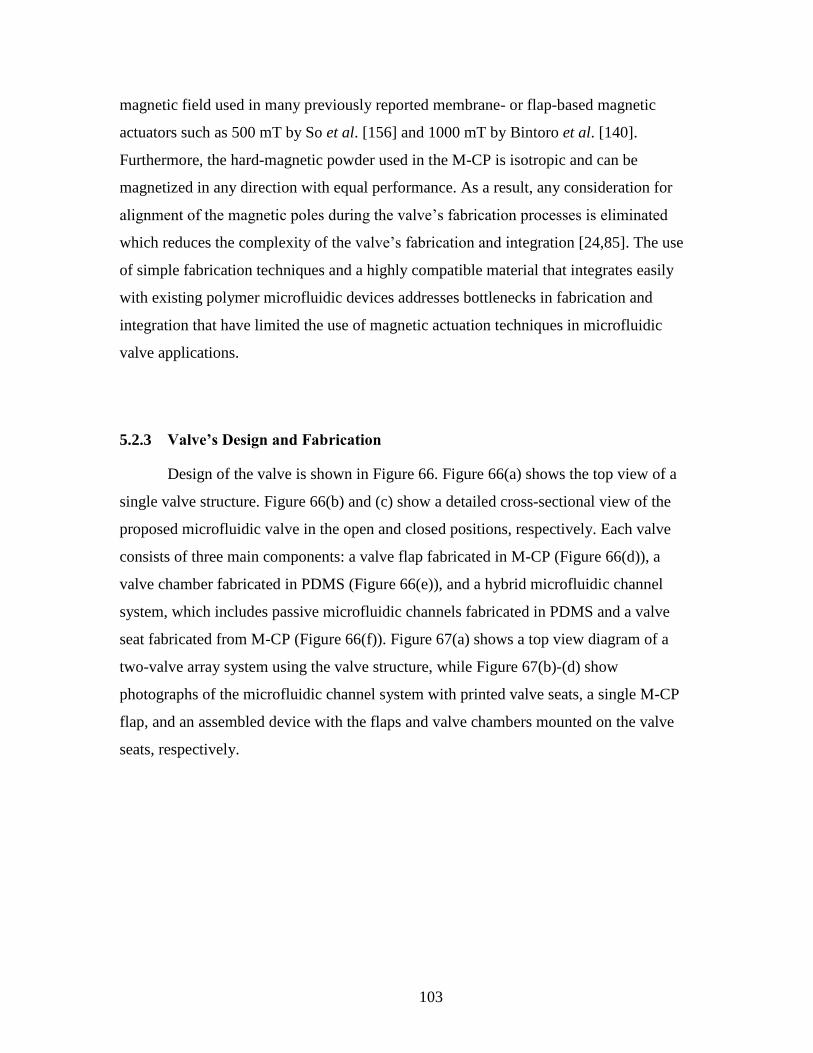
103
magnetic field used in many previously reported membrane- or flap-based magnetic
actuators such as 500 mT by So et al. [156] and 1000 mT by Bintoro et al. [140].
Furthermore, the hard-magnetic powder used in the M-CP is isotropic and can be
magnetized in any direction with equal performance. As a result, any consideration for
alignment of the magnetic poles during the valve’s fabrication processes is eliminated
which reduces the complexity of the valve’s fabrication and integration [24,85]. The use
of simple fabrication techniques and a highly compatible material that integrates easily
with existing polymer microfluidic devices addresses bottlenecks in fabrication and
integration that have limited the use of magnetic actuation techniques in microfluidic
valve applications.
5.2.3 Valve’s Design and Fabrication
Design of the valve is shown in Figure 66. Figure 66(a) shows the top view of a
single valve structure. Figure 66(b) and (c) show a detailed cross-sectional view of the
proposed microfluidic valve in the open and closed positions, respectively. Each valve
consists of three main components: a valve flap fabricated in M-CP (Figure 66(d)), a
valve chamber fabricated in PDMS (Figure 66(e)), and a hybrid microfluidic channel
system, which includes passive microfluidic channels fabricated in PDMS and a valve
seat fabricated from M-CP (Figure 66(f)). Figure 67(a) shows a top view diagram of a
two-valve array system using the valve structure, while Figure 67(b)-(d) show
photographs of the microfluidic channel system with printed valve seats, a single M-CP
flap, and an assembled device with the flaps and valve chambers mounted on the valve
seats, respectively.

104
Figure 66: (a) Top view of a microfluidic system with a single valve structure, (b) cross-
sectional view of the function of a single valve in open valve position, (c) cross-sectional
view of the function of a single valve in closed valve position (the permanent magnet is
employed to actuate the valve flap), (d) a valve flap fabricated in M-CP (6 mm in
diameter), (e) a valve chamber fabricated in PDMS, (f) a hybrid microfluidic channel
system, which includes passive microfluidic channels fabricated in PDMS and a valve
seat fabricated from M-CP. These diagrams are for illustration purpose and do not
represent exact dimensional ratios. This image is reprinted with permission from [126].
105
Figure 67: (a) Top view of a microfluidic channel system with printed M-CP valve seats
(two valves are shown in a flow switching configuration), (b) photographs of the
microfluidic channel system with printed valve seats (thickness of the valve seats = 200
µm, diameter of the valve seats = 6 mm), (c) photograph of a single M-CP valve flap
(diameter of the valve flap = 6 mm), (d) photograph of an assembled device with the flaps
and valve chambers mounted on the valve seats. This image is reprinted with permission
from [126].
5.2.4 Valve’s Fabrication Process
Figure 68 shows a cross-sectional view of the fabrication process steps for the
microfluidic channel system and valve seat shown in Figure 67(b). The microfluidic
channel system is first fabricated in PDMS and then the M-CP valve seat is printed on the
top surface using a shadow mask. The microfluidic channel system micro-molds are
fabricated by one of the following two ways: 1) using a poly(methyl methacrylate)
(PMMA) substrate micro-patterned using a CO2 laser ablation system (Universal Laser
System’s VersalLASER©
), or 2) using SU-8 on a silicon substrate fabricated by standard
photolithography techniques. PDMS is then poured onto the micro-mold, degassed for 30
minutes, cured at 80 °C for two hours, and de-molded. To create the M-CP valve seat, a
thin layer (200 m) of M-CP is printed with a shadow mask on the top surface of the
PDMS channels at the location where the valve flaps are assembled in later steps (Figure
68(d)-(h)). After printing the M-CP valve seat on the PDMS, the M-CP is cured at 80 °C

106
for 15 minutes. The M-CP is then permanently magnetized by inserting the microfluidic
chip into a 1.8 ± 0.2 Tesla external magnetic field (provided by a custom made
magnetizer by Dexter Magnetic Technologies Inc., Elk Grove Village, Illinois, USA).
The attraction between the permanently magnetized valve seat and valve flap facilitates a
strong contact between the flap and the valve seat, improving sealing between the two
components and reducing the risk of leakage due to poor surface contact. In addition, the
attraction force between a permanently magnetized valve flap and seat provides a
latching mechanism for the closed valve position. To the author’s knowledge, this is the
first reported use of permanently magnetized valve seat to enhance sealing in a polymer
based microfluidic valve. Further details of the effect of the M-CP valve seat on the
valve’s performance are presented in Section 5.2.5.1. In the next step (Figure 68(i)), inlet
and outlet holes are punched using a 21 gauge needle, creating access holes 0.82 mm in
diameter. To seal the channels, the PDMS microfluidic channel system is permanently
bonded to a glass slide (1“ 3”, or 2.54 cm 7.62 cm) by corona surface activation
techniques using a Corona Treater model BD-20AC by Electro-Technic Products Inc.
(Figure 68(j)).

107
Figure 68: Fabrication process of the microfluidic channel systems and M-CP valve seat.
(a) patterning of PMMA mold using a Universal Laser System’s VersalLASER© CO2
laser ablation system, or SU-8 mold using standard soft lithography techniques, (b)
molding of PDMS microfluidic channel system, (c) de-molding of PDMS, (d-h)
patterning of the valve seat, a thin (200 µm) layer of M-CP on top of the microfluidic
channel system using shadow mask screen printing, (i) punching inlet/outlet holes using a
21 gauge dispensing needle, (j) bonding the PDMS channels to a glass slide substrate
using plasma surface activation technique. This image is reprinted with permission from
[126].
The M-CP flaps are fabricated using the same fabrication process steps previously
shown in Figure 65. Similar to the valve seat, the M-CP flap is then permanently
magnetized by inserting the microfluidic chip into a 1.8 ± 0.2 Tesla external magnetic
field (provided by the same custom-made magnetizer). Finally, the valve chambers are
fabricated out of un-doped PDMS using standard soft lithography techniques and PMMA
molds.
For fabrication of the microfluidic valves presented in this thesis, the three parts
are manually aligned and assembled. Due to the relatively large size of the parts (M-CP
flap’s diameter = 6 mm), the assembling process is relatively straight forward. However,
for high throughput and large scale fabrication, a more automated method should be
developed for higher placement precision and faster fabrication process.

108
5.2.5 Experimentation Results and Discussion
In this section, the performance of the valve as both an on/off fluidic switch, and
in an array as a flow steering element, is discussed. The results of valve actuation
mechanism optimization are also presented. Finally, a comparison between the structure
and performance of the microfluidic valve presented in this thesis and previously reported
membrane- or flap-based magnetic valves is presented in Section 5.2.6.
For all valve tests presented in this manuscript, the inlet reservoirs of the
microfluidic channels are connected to a Harvard Apparatus model 11 syringe pump
through polyurethane tubing, as shown in Figure 69. The tubes are fixed to the inlet hole
using silicone sealant (34 Flowable Sealant from Dow Corning®). The microfluidic chips
are then mounted under a microscope for visual monitoring. A dark blue dye solution
containing de-ionized water and hand soap foam is used to visualize the flow. The
presence of air bubbles in the foam greatly enhances the ability to visually monitor the
fluid flow under the microscope to determine the pressure at which the closed valves fail
and start to leak, which is the burst pressure of the valves. A digital pressure gauge
(MediaGauge MGA-30-A-9V-R by SSI Technologies) is mounted on the syringe to
measure the burst pressure (Figure 69).
Figure 69: Test setup used for the evaluation of valve performance.
For the actuation of the valves presented in this chapter, small permanent
magnets, 6 mm in diameter and 3.54 mm in height, are used. The permanent magnets are
located 1 mm below the microfluidic channel systems to provide an 80 mT magnetic field
109
at the M-CP valve seats location. A 5180 Hall Effect portable Gauss/Tesla meter by F.W.
BELL®
is used to measure the magnetic field at the M-CP valve seat. An 80 mT actuation
magnetic field is chosen, as it provides sufficient actuation force for the valve application
to perform effectively in both on/off and flow steering configurations.
5.2.5.1 Performance Characterization of a Single Valve as an On/Off Valve
In this section, the effect of having a permanently magnetized M-CP valve seat on
the valve performance is discussed first by comparing the burst pressure of valves with
M-CP valve seats to valves with un-doped PDMS valve seats. This section also discusses
the performance of a single valve to completely block the flow of the liquid in a
microfluidic channel system when configured as an on/off valve. Finally, the dead
volume of a single valve is evaluated.
To show the effect of the M-CP valve seat on the valve performance, as well as to
characterize the performance of a single valve, straight channels consisting of a single
valve chamber similar to the one shown in Figure 70 are fabricated. Two different sets of
microfluidic valves are fabricated for testing, both with a flap thickness of approximately
2.3 mm. One set uses the valve seat shown in Figure 68, fabricated using M-CP as
described previously in Section 5.2.4. The valve seat is permanently magnetized with a
1.8 ± 0.2 Tesla magnetic field with the same polarity as the valve flap. In this device,
both valve flap and valve seat are permanently magnetized; thus, there is an attraction
force between the valve seat and the valve flap in the absence of any external magnetic
field. In the second set of tests, the valve seats are fabricated following similar fabrication
steps as the ones shown in Figure 68, except the valve seats are fabricated using un-doped
PDMS with no magnetic particle filler. The devices are connected to the pressure sensor
to measure the burst pressure for valves without applying any external magnetic actuation
force. The results for these burst pressure tests comparing the two different valve seats
are shown in Table 10.

110
Figure 70: Schematic of the microfluidic device used for determining a single valve’s
burst pressure in its closed position. This image is reprinted with permission from [126].
Table 10: Burst pressure for valve designs with permanently magnetized M-CP valve seat
and non-magnetic PDMS valve seat in the absence of any external magnetic field (flap
thickness = 2.3 ± 0.1 mm, valve seat thickness = 200 ± 10 µm, microfluidic system
channels sized 200 µm wide and 200 µm deep, flow rate of 1 mL/min). The
measurements are done on 3 valves for each M-CP valve seat and un-doped PDMS valve
seat. This data is reprinted with permission from [126].
Average Burst Pressure
(kPa)
PDMS Valve Seat 0.340.20
M-CP Valve Seat 5.52 0.34
As can be seen from Table 10, the M-CP valve seat provides a much higher
attraction force between the flap and the valve seat, allowing complete blockage of fluid
flow for pressures up to 5.52 kPa for a 2.3 mm thick valve flap with a 200 ± 10 m thick
valve seat. The microfluidic channel systems used for these tests have a channel size of
200 µm wide and 200 µm deep. A flow rate of 1 mL/min is used for these tests. A regular
PDMS valve seat with no magnetic particles has a measured burst pressure of 0.34 kPa.
111
The small, yet non-zero value, for the un-doped PDMS may be attributed to either
experimental error or surface effects.
This result is particularly useful for applications such as flow steering between
multiple channels under continuous flow condition where there is always an open path for
the fluid flow at any given time. In such low pressure applications, where the fluid
pressure in the microfluidic channels does not build up to a pressure above 5.52 kPa, the
valves presented here can be considered as normally closed switches. For applications
with higher pressure than 5.52 kPa, the valves with 2.3 mm thick flap would be
considered as normally open valves and an active external magnetic force would be
required to keep a valve in its closed position.
Valves with M-CP valve seats are further characterized for the effect of flap
thickness on burst pressure. A small permanent magnet, 6 mm in diameter and 3.54 mm
in height, is located 1 mm below the microfluidic channels system to provide an 80 mT
magnetic field at the M-CP valve seat location for the valve actuation. Valves with flap
thicknesses ranging from 0.3 to 2.3 mm are tested for burst pressure when actuated. The
experimental results for these tests are presented in Figure 71. A 2.3 mm thick valve flap,
the thickest tested flap, is able to block the flow completely without any leakage for
pressures up to approximately 9.65 kPa. Higher leakage pressures can be achieved by
increasing the flap thickness further, or by increasing the strength of the actuation
magnetic field.

112
Figure 71: Results of the burst pressure measurements performed on valves with different
flap thicknesses actuated under an 80 mT magnetic field. Five valves are used for each
flap thickness. Accuracy for the flap thickness measurements is ± 0.1 mm. Vertical error
bars represent one standard deviation over 5 valves at each flap thickness. This image is
reprinted with permission from [126].
By dividing the data obtained from Figure 11 for the force measurement by the
surface area of the samples we can obtain a first order approximation of the pressure
produced by the M-CP material actuated under an 80 mT external magnetic field (Figure
72).
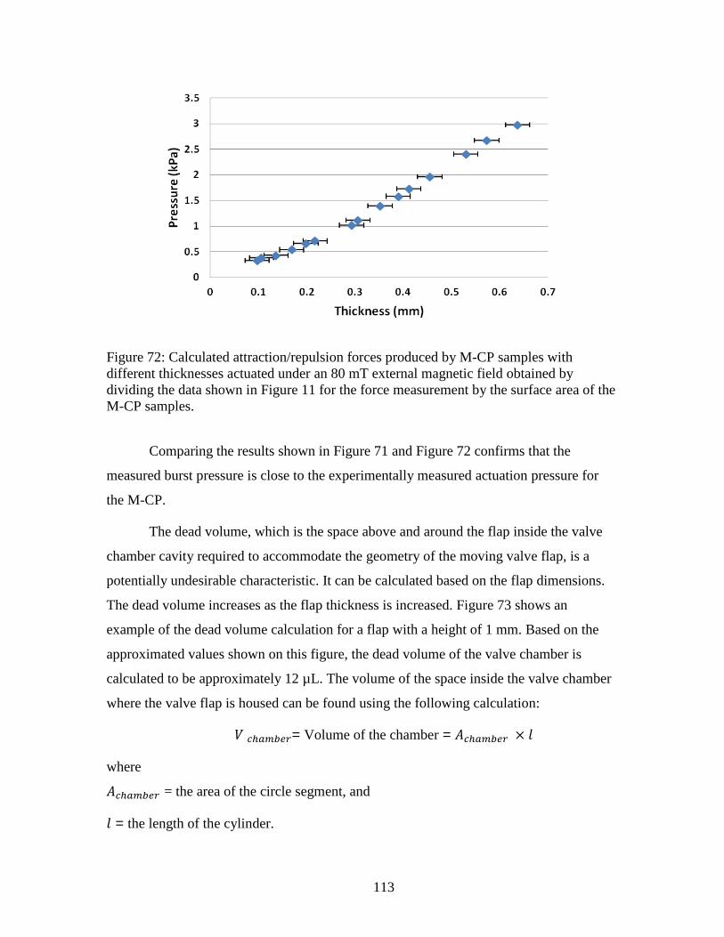
113
Figure 72: Calculated attraction/repulsion forces produced by M-CP samples with
different thicknesses actuated under an 80 mT external magnetic field obtained by
dividing the data shown in Figure 11 for the force measurement by the surface area of the
M-CP samples.
Comparing the results shown in Figure 71 and Figure 72 confirms that the
measured burst pressure is close to the experimentally measured actuation pressure for
the M-CP.
The dead volume, which is the space above and around the flap inside the valve
chamber cavity required to accommodate the geometry of the moving valve flap, is a
potentially undesirable characteristic. It can be calculated based on the flap dimensions.
The dead volume increases as the flap thickness is increased. Figure 73 shows an
example of the dead volume calculation for a flap with a height of 1 mm. Based on the
approximated values shown on this figure, the dead volume of the valve chamber is
calculated to be approximately 12 µL. The volume of the space inside the valve chamber
where the valve flap is housed can be found using the following calculation:
= Volume of the chamber =
where
= the area of the circle segment, and
= the length of the cylinder.

114
can be calculated using the following formula:
where
r is the radius of the circle of which the segment is a part = 3.2 mm
h is the height of the segment = 3.4 mm
The total volume of the space inside the valve chamber where the valve flap is
housed can be calculated using the following formula:
mm2
mm3
The volume of the flap inside the valve chamber can be divided into two parts.
The volume of the thick section of the flap, , and volume of the thin part of the
flap inside the chamber,
= volume of the thick segment of the flap = Volume of the cylinder/2
=
=14.1 mm
3
and
volume of the thin segment of the flap inside the valve chamber
= mm3
Therefore, the dead volume can be calculated as follows:
mm3

115
Figure 73: Diagram of geometry used for the approximation of dead volume in a valve
structure with a flap thickness of 1 mm and a gap size of 0.5 mm on top of the flap. This
image is reprinted with permission from [126].
The 0.5 mm gap above the flap is chosen for ease of fabrication and assembly in
prototyping. The dead volume could be further reduced in this case by decreasing the size
of gap between the flap and the top layer of the cavity from 500 to 200 µm, which is the
channel depth for the underlying microfluidic channel system.
Viewed together, these results show that a thicker flap structure increases the
burst pressure and the valve flap should be made as thick as possible to allow the valve
design to be as robust as possible. On the other hand, there is a direct relationship
between the valve’s dead volume and the flap thickness: excess thickness increases the
undesired dead volume, affecting miniaturization and density of the devices. Ultimately,
the valve must be designed for sufficiently large burst pressure for the system being
designed, while also minimizing the dead volume, as the two characteristics result in a
trade-off.
5.2.5.2 Operation of Multiple Valves for Flow Switching
In this section, arrays of two parallel valves are fabricated and tested to evaluate
use of the valve design in arrays and flow routing mechanisms in continuous flow
applications (Figure 74). In many applications, it is important to be able to route flow
through the different pathways in a system without disturbing the flow rate in a

116
continuous flow situation. Furthermore, the valves developed in this thesis are also
intended to be part of the µROAMS platforms previously described in Section 1.1 in
which samples are manipulated throughout a device according to reconfigurable flow
paths, which requires flow switching between multiple channels using a valve array. As
shown in Figure 74 , the two parallel valves are used to regulate fluid flow direction
within the microfluidic system by switching the flow from one branch of a Y-shaped
channel to the other, with one valve in each branch. Small permanent magnets providing
80 mT at each M-CP valve seat location are used for actuation of the valve flaps. A
similar test setup to that shown in Figure 69 is connected to the array of two parallel
valves for the flow switching tests. In these tests, the flow direction is switched between
the two branches of the Y-shaped channel by near-simultaneously opening one valve and
closing the other. As a result, the flow path (inlet to outlet) is not fully blocked at any
time during operation and continuous flow is successfully maintained in one of the two
branches. The valves show great performance for regulating flow, and are tested for flow
rates as high as 1 mL/min in microfluidic channels 200 µm wide and 200 µm deep, and
up to 5 mL/min for larger channels 1 mm wide and 500 m deep. The fact that a 2.3 mm
thick flap is able to stop the flow for pressures up to 9.65 kPa means that such valve can
be used to successfully change the flow direction in, for example, a 10 cm long
microfluidic flow path with the following microfluidic channel cross-sectional
dimensions: width =200 µm, height = 200 µm for flow rates as high as 280 µL/min
(resulting in a back pressure of 9.1 kPa). This is acceptable considering the typical flow
rate for many microfluidic systems ranges from few μL/min to tens of μL/min
[21,23,31,79,105,139,140,155–159].

117
Figure 74: Microfluidic channel system designed to test the performance of the valves in
an array for flow switching between two branches in a Y-shaped microfluidic channel
system. This image is reprinted with permission from [126].
5.2.5.3 Actuation Mechanism
A method of controlling the external magnetic field applied to each valve is
needed to provide electrical actuation control of each valve in an array. An
electromagnet-based array, where each valve is under separate electromagnetic control, is
currently under development by other researchers in µIL [160]. For the purposes of the
testing detailed in this thesis, permanent magnets are mounted on miniature linear motors,
which are then used to move the permanent magnets under the appropriate valves, as
shown in Figure 75. In this configuration, the permanent magnet is used to hold a given
valve in the closed position. To open the valve, the linear motor is actuated to move the
magnet away from the flap, allowing fluid pressure to build up behind the flap, thus
opening the valve. In addition to providing an easy platform for testing, this set-up also
enables testing of important parameters required for determining the best method to
actuate an array of valves using external fields, such as the most effective direction to
move the permanent magnet under the valve for the sharpest and most effective transition
from the closed valve position to the open valve position, and vice versa.
The motion of the linear motor between open and closed positions is shown in
Figure 75. This method, when used with an array of linear motors, provides individual
electrically-controlled actuation of each valve in an array. Furthermore, each linear motor
only consumes power when the motor is moving the permanent magnet to change the
valve state. This is an advantage over magnetic actuation mechanisms using
electromagnets, which require power to be continuously applied to keep the valve at its

118
closed position. This issue is addressed by using a permanent magnet mounted on a
miniature linear motor, as well as latching force supplied by the magnetized M-CP valve
seat. This method provides bi-stable actuation that does not consume any power when not
switching.
A single Miniature Linear Motion Series PQ12 (Firgelli Technologies Inc.) is
used for the proof-of-concept of this magnetic force application technique, as shown in
Figure 75 and Figure 76. Figure 75 shows a cross-sectional view of the experimental
setup, where a single valve is shown for demonstration purposes.
Figure 75: Diagram of the microfluidic system used to test the valve’s actuation
mechanism. (a) top-down view, (b) cross-sectional view of the valve chamber with the
actuation mechanism for providing the external magnetic force to the valve. This diagram
includes the miniature linear motor and permanent magnet located under the valve
chamber. This diagram is for illustration purpose and does not represent exact
dimensional ratios.

119
Figure 76: Miniature Linear Motion Series PQ12 from Firgelli Technologies Inc. used to
move an external magnetic field, as provided by a small permanent magnet, to actuate
different valves in the microfluidic system.
In the experiments previously described in Sections 5.2.5.1 and 5.2.5.2, magnetic
actuation is only used to hold the valve flap in the closed position. The valve is opened by
relying on the pressure of the liquid to push the valve flap open when the permanent
magnet moves away from the valve seat. However, a common issue with PDMS-based
microfluidic systems is failure of moving elements due to static friction between the
moving parts in the device. For the valve presented in this chapter, it is discovered
through testing that there is a 20% chance of the valve failing to open properly after
switching to the open valve position at least once during 50 actuation cycles for valves
operating at 200 L/min flow rate. This is likely due to the inability of the fluid pressure
to immediately overcome the static friction between the flap and the valve seat, thus
interrupting the continuous fluid flow. As one of the major design goals is to achieve a
reliable routing system for continuous flow conditions, this issue has to be addressed.
Active bi-directional actuation, where the valve is forced both open and closed by a
magnetic field, is employed to improve the performance of the valve. The permanent
magnetization of the valve flap actuator facilitates this bi-directional operation. Figure 77
shows an example of such bi-directional actuation, where two small, oppositely polarized
permanent magnets are attached to a linear motor. Conversely, an electromagnet can be
used, and the opposite polarities can be achieved by reversing the electromagnet’s
current. However, this solution will require continuous current to hold the valve closed.
A reversed magnetic field actively repels the flap and forces the valve open, as the
M-CP is permanently magnetized and retains its specified polarity. Soft-magnetic Fe-
based particles used in previous microfluidic designs by other researchers can only be
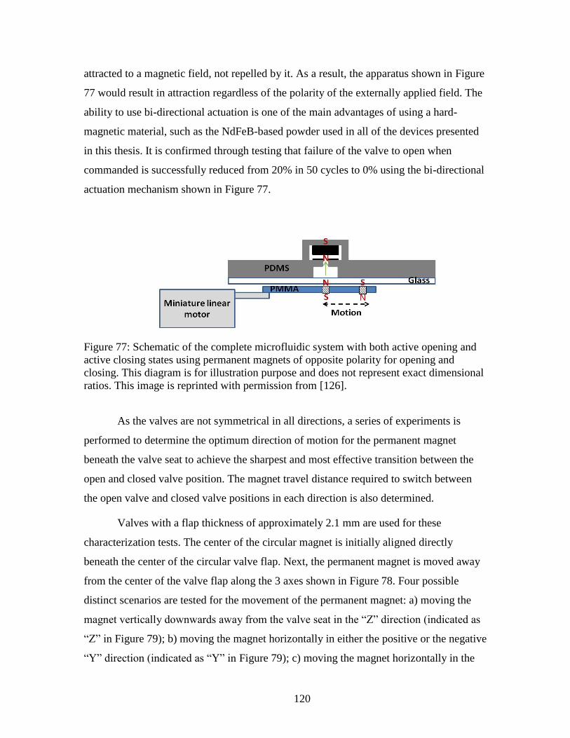
120
attracted to a magnetic field, not repelled by it. As a result, the apparatus shown in Figure
77 would result in attraction regardless of the polarity of the externally applied field. The
ability to use bi-directional actuation is one of the main advantages of using a hard-
magnetic material, such as the NdFeB-based powder used in all of the devices presented
in this thesis. It is confirmed through testing that failure of the valve to open when
commanded is successfully reduced from 20% in 50 cycles to 0% using the bi-directional
actuation mechanism shown in Figure 77.
Figure 77: Schematic of the complete microfluidic system with both active opening and
active closing states using permanent magnets of opposite polarity for opening and
closing. This diagram is for illustration purpose and does not represent exact dimensional
ratios. This image is reprinted with permission from [126].
As the valves are not symmetrical in all directions, a series of experiments is
performed to determine the optimum direction of motion for the permanent magnet
beneath the valve seat to achieve the sharpest and most effective transition between the
open and closed valve position. The magnet travel distance required to switch between
the open valve and closed valve positions in each direction is also determined.
Valves with a flap thickness of approximately 2.1 mm are used for these
characterization tests. The center of the circular magnet is initially aligned directly
beneath the center of the circular valve flap. Next, the permanent magnet is moved away
from the center of the valve flap along the 3 axes shown in Figure 78. Four possible
distinct scenarios are tested for the movement of the permanent magnet: a) moving the
magnet vertically downwards away from the valve seat in the “Z” direction (indicated as
“Z” in Figure 79); b) moving the magnet horizontally in either the positive or the negative
“Y” direction (indicated as “Y” in Figure 79); c) moving the magnet horizontally in the

121
negative “X” direction (indicated as “-X” in Figure 79); and d) moving the magnet in the
positive “X” direction (indicated as “+X” in Figure 79). In each set of tests, the magnet is
moved in 1 mm intervals and the resulting burst pressure is recorded. The results of these
measurements are shown in Figure 79.
Figure 78: Illustration of the setup used to determine the most effective direction for
moving the magnet as determined by the sharpest transition from closed valve position to
open valve position. The axes indicate the direction along which the permanent magnet is
moved. This image is reprinted with permission from [126].

122
Figure 79: Effect of the different directions in which the permanent magnet is moved
under the valve on the valve’s performance when switched between open and closed
valve positions. These results indicate that moving the permanent magnet in the “-X”
direction provides the sharpest transition from closed valve position to open valve
position. This image is reprinted with permission from [126].
Along the X and Y axis, the magnet is moved in both positive and negative
directions. As expected, there is no significant difference for the results obtained in the
two different directions along the Y axis because the valve design is symmetric in this
direction. However, the results for the opposite directions along X axis are very
distinctive due to the asymmetric shape of the valve flap in this direction.
The experimental results show that moving an externally applied magnetic field in
the “-X” direction provides the most effective actuation, with the sharpest transition from
closed valve to open valve, among the 4 different aforementioned scenarios which is
explained below. As shown in Figure 79, as the magnet is moved in the “-X” direction,
the burst pressure initially increases and then drops with a much greater rate than any of
the other directions, which provides the sharpest transition between open and closed
valve positions as described below. This is a result of the magnetic field set up produced
by the permanent magnet, which is shown in Figure 80. The lines in Figure 80 show a
simplified illustration of the magnetic field of both the permanent magnet and the M-CP
valve flap. As the magnet moves in the “-X” direction, the center of the magnet aligns
with the center of the thickest part of the flap, providing the maximum attraction force.
This causes the burst pressure to increase from the 8.82 kPa initial value. By moving the

123
magnet further, the attraction force rapidly decreases because there is less overlap
between the permanent magnet and the M-CP flap (point C on Figure 79). Eventually, the
misalignment becomes large enough that the magnetic field from the edge of the magnet
becomes effective and starts to repel the flap (point D on Figure 79). This repulsion drops
the burst pressure to below 5.52 kPa, which is the burst pressure measured in absence of
any external magnetic field. The smooth transition between the points is due to the
continuous change in the actuation magnetic field acting on the flap as the permanent
magnet is moved from point A to perfect alignment in point B, maximum burst pressure,
and then position D where the magnetic field from the edge of the permanent magnet
starts to repel the M-CP flap as shown in Figure 80.
Figure 80: This simplified schematic illustrates the interaction between the magnetic field
(illustrated as magnetic field lines) of the permanent magnet and the valve flap as the
external magnet field is moved away from the valve’s center. This image is adapted with
permission from [126].
A similar phenomenon affects a valve when the externally applied magnetic field
(permanent magnet) is moved in the “+X” and the “Y” directions. However, the effect of

124
this phenomenon on the burst pressure is not significant in these cases because the thin
segment of the step-shaped flap is fixed under the valve chamber cover and is not free to
move as a result of the repulsion force. Therefore, the most effective actuation scenario is
as follows:
Closed position: Aligning the center of the permanent magnet (externally applied
magnetic field) with the center of the free-moving part of the flap (i.e. the thick
section), shown as position B in Figure 79 and Figure 80.
Open position: Moving the externally applied magnetic field at least 3 mm away
from the central position in the “-X” direction, shown as position D in Figure 79
and Figure 80.
It should be noted that, although the prototype actuation design can easily be used
for small and medium sizes of valve arrays, it becomes increasingly complicated to
physically integrate linear motors for valve actuation into a microfluidic system with an
increasingly high number of valves in the array. The footprint of each linear motor is
much bigger than the valve itself, which can be a limiting factor for miniaturization. To
provide a more scalable design for a large array containing tens or hundreds of valves,
other researchers in µIL are investigating the replacement of the linear motor, used to
demonstrate the valve developed in this thesis, with a solution that requires a smaller area
and power footprint.
5.2.6 Comparison with the Prior Art
In this section, structural properties and performance of the step-shaped flap
actuators presented in this thesis are compared with prior membrane- and flap-based
magnetic microfluidic valves from other researchers. The structural properties and
performance are shown in Table 11 and Table 12, respectively.

125
Table 11: Structural properties of membrane- and flap-based magnetic microfluidic
valves. This data is reprinted with permission from [126].
Type
Structural materials
Size
(mm2)
Dis
pla
cem
ent
(m
)
Fa
bri
cati
on
com
ple
xit
y
Magnetic
material Valve seat
Support
structures
Polymer
based
actuator
Flap
[21]
NiFe and
Magnetic
foila
Rubber
ring glued
to NiFe
orifice
NiFe
Si No 100 150 High
c
Membrane
[155] Si Si
plated Ni-
Fe and Si No 40
Several
µm High
c
Membrane
[140] NiFe
Au
NiFe
Si/SiO2 No 0.79 12 High
c
Membrane
[105]
Si/Al
plated on
PDMS
N/A Si/SiO2 No 81 50 Highc
Membrane
[23]
NiFe
CoNiMnPb
Au NiFe
Si No
2
2 30 High
c
Membrane
[156]
PDMS
doped with
iron oxide
N/A PDMS Yes 15 -- Lowd
Valve
presented
in this
thesis
Rare-earth
M-CP
Rare-earth
M-CP PDMS Yes 100 500 Low
d
a A piece of rolled magnetic coil (1.5 mm 5 mm) is mounted on the NiFe membrane.
b The CoNiMnP hard-magnetic material is electroplated on a NiFe membrane.
c The fabrication process requires multiple steps of overly complicated surface
micromachining processes. d The fabrication process can be done with relatively low cost prototyping equipment and
involves process steps with relatively low complexity.

126
Table 12: Comparison of the performance of membrane- and flap-based magnetic
microfluidic valves. This data is reprinted with permission from [126].
Valve type Latching Bi-directional
actuation
Actuation
magnetic
field strength
(mT)
Flow
rate
(l/min)
Leakage
rate
(l/min)
Burst
pressure
(kPa)
Flap [21] Yes Yes 4 3-30 NSa
2
Membrane
[155] No No NS
a 100 NS
a NS
a
Membrane
[140] Yes Yes 1000 1 0.03 30
Membrane
[105] No No NS
a N/A N/A 1.4-2
Membrane
[23] Yes Yes NS
a 10-50 0.16-0.8 7.8
Membrane[15
6]b
No No 500 120 NS NS
Valve
presented in
this thesis
Yes Yes 80 1000d
0 9.65c
a NS = Not Specified in the paper
b The membrane actuator developed in [156] is tested for drug delivery applications as an
pumping element and not for valve applications. Therefore, the performance of the
membrane actuator as a microfluidic valve is not characterized in the paper. c This result is for valves with flap thickness of approximately 2.3 mm actuated under 80
mT magnetic field. d This result is for a microfluidic channel system with channels sized 200 µm wide and 200
µm deep. Flow rates up to 5 mL/min for larger channels of up to 1 mm wide and 500 m
deep was achieved. However, because the widths of the larger channels are in mm range, 1
mm wide, this result is not shown in the comparison table.
Among the membrane- or flap-type valves listed in Table 11 and Table 12, the
membrane actuator reported by So et al. [156] is the only one that features an all-
polymer actuator, and as a result it is the closest example to the valve structure presented
in this thesis. Their magnetic membrane actuator uses PDMS doped with a soft-magnetic
material, iron oxide powder, to create a magnetic polymer. The use of a Fe-based soft-
magnetic material means that a relatively large external magnetic field of 500 mT is
required to actuate the membrane. It should be noted that the membrane actuator
developed by So et al. in [156] is tested as a pumping element for drug delivery

127
applications and not for valve applications. Therefore, the performance of the membrane
actuator as a microfluidic valve is not characterized in the paper.
All the other valve structures listed in Table 11 and
Table 12: Comparison of the performance of membrane- and flap-based magnetic
microfluidic valves. This data is reprinted with permission from [126].
are based on complicated surface and bulk micromachining of Si and metallic
layers. In comparison, the simple fabrication techniques described in this thesis, based on
low-cost polymer material, makes it much more suitable for the development of low cost
disposables and rapid prototyping polymeric systems, as well as easier integration into
sophisticated polymer based microfluidic systems. Furthermore, as can be seen in Table
11 and
Table 12: Comparison of the performance of membrane- and flap-based magnetic
microfluidic valves. This data is reprinted with permission from [126].
, these advantages do not come with a significant sacrifice on the valve
performance, with the valve presented in this thesis being comparable with prior devices
in terms of burst pressure, maximum flow rate and the required actuation magnetic field
strength.
5.3 Summary and Conclusion
In this chapter, a step-shaped flap actuator is developed using the hard-magnetic
composite polymer. The hard-magnetic M-CP structures used for the valve actuator can
achieve high forces and large, bi-directional displacement. The proposed step-shaped
flap actuator design is easy to integrate with other commonly used PDMS-based
microfluidic components, as well as other active microfluidic components that use the
same novel M-CP material, including the ones presented in this thesis such as cilia
actuators presented in Chapter 4 and membrane actuators presented in Chapter 6.
Furthermore, the performance of this step-shaped M-CP flap actuator is demonstrated as
an active magnetically-actuated all-polymer microfluidic valve. The design, fabrication,

128
and detailed performance characterization of the new microfluidic valve is also presented
in this chapter. This new valve also employs the same M-CP material in a novel magnetic
valve seat that enhances the valve’s performance. Furthermore, similar to what was
earlier discussed for the cilia actuators in Chapter 4, the valves presented in this thesis
can be fabricated into arrays for the creation of complex microfluidic systems. This
design avoids the use of non-polymeric hard-magnetic solid pieces and metallic thin films
incorporated into many of the previous magnetic microfluidic valve designs, giving this
valve the advantages of easy fabrication, easy integration, and high degree of flexibility,
as well as resilience against mechanical failure. Experimental results presented in this
chapter show that the valve can function as either an on-off valve for completely stopping
flow inside a microfluidic channel, or in arrays to regulate the flow direction inside a
microfluidic system with parallel flow channels. It is demonstrated that a 2.3 mm thick
step-shaped flap, 6 mm in diameter, and actuated under an 80 mT magnetic field
completely stops fluid flow in a single microfluidic channel, sized 200 µm wide and 200
µm deep, for pressures up to 9.65 kPa. In an array, this valve design also shows high
performance for flow switching between multiple microfluidic channels under continuous
flow conditions. An array of valves for flow routing is demonstrated for flow rates up to 5
mL/min in relatively larger microfluidic channels of up to 1 mm wide and 500 m deep.
Failure of the valve to open when commanded within the first 50 on/off cycles is
successfully reduced from 20 % to 0 % through an active opening scheme, which is made
possible due to the bi-directional actuation capability of the permanently magnetized M-
CP material used in the valve design. Use of an M-CP valve seat provides a latching
mechanism for pressures up to 5.52 kPa for a 2.3 mm thick flap actuated under an 80 mT
magnetic field, as well as ensuring close contact and strong sealing between the valve
flap and seat, further enhancing the valve’s performance. Finally, optimization tests are
performed on the actuation mechanism to find the effective actuation scheme that can
provide the most effective transition from closed valve position to open valve position
and vice versa. Future work will include replacement of the miniature linear motor with a
different mechanism that will significantly reduce the area and power footprint of the
actuation mechanism and will be more suitable for integration of a large number of
valves.

129
5.4 Related Publications
The results of this work have been presented at the following peer reviewed
conferences:
1. Rahbar, M., Shannon, L., Gray, B. L., “Arrayable Microfluidic Valves Based
on Rare Earth Permanently Magnetic Polymer for Use in Microfluidic Flow
Switching,” MicroTAS Proceedings The 18th International Conference on
Miniaturized Systems for Chemistry and Life Sciences, 45, 2014. (Selected for
oral presentation at MicroTAS conference. Less than 10% of the submitted
papers were accepted for oral presentation)
2. Rahbar, M., Shannon, L., Gray, B. L., “Design, fabrication and
characterization of an arrayable all-polymer microfluidic valve employing
highly magnetic rare-earth composite polymer,” Journal of Micromechanics
and Microengineering, 26, 0055012, 2016.

130
Chapter 6 - Hybrid M-CP/PDMS Actuators for Large and Bi-
directional Surface Deflections4
In addition to cilia and flap-type actuators, actuators used to deflect the surface of
a device are another commonly used type of actuator for many microfluidic systems. For
example, surfaces that are supported in all sides, membrane actuators, are used in many
applications, including but not limited to microfluidic pumps and valves
[23,105,140,155,156]. In this section, the focus is on development of an effective hybrid
M-CP/PDMS actuator capable of providing large and bi-directional cyclic actuation on
the surface of PDMS devices with microfluidic structures patterned on the surface, which
can be easily integrated with other PDMS based microfluidic systems. The hybrid M-
CP/PDMS actuators used for surface deflection developed in this thesis needs to be also
compatible with other magnetic actuators based on the same M-CP material including the
other M-CP component developed in this thesis and previously described in Chapters 4
and 5.
There are three main motivations for the development of the hybrid M-CP/PDMS
actuator described in this chapter. These main motivations are explain bellow:
As previously shown in Section 3.3.1, M-CP (PDMS doped with rare-earth
magnetic powder with a weight percentage of 80 wt-%) results in a relatively
stiffer membrane when compared to the un-doped PDMS, requiring larger
external forces for actuation. This means increased electromagnetic fields are
required for effective actuation of a doped actuators as compared to one without
any particles. Use of a hybrid M-CP/PDMS actuator with the majority of the
surface made out of un-doped PDMS increases the overall compliancy and
actuation range of the actuator due to the much higher elasticity of un-doped
PDMS. This higher elasticity also provides a higher degree of conformity.
Therefore, a hybrid M-CP/PDMS actuator needs less magnetic force to actuate the
membrane and as a result a smaller magnetic field can be utilized for the actuation
mechanism.
In addition, doping of PDMS with rare-earth magnetic powder makes it opaque to
visible and ultraviolet (UV) light. Loss of transparency can be a big limitation in
many applications where visual monitoring and optical detection of samples are
required such as the cell manipulation platform developed and explained later in
this chapter (Section 6.2). Using a hybrid M-CP/PDMS structure limits the
4 The material presented in this section is based on the work that has been published in [109,125]
with permission.

131
regions of the actuator that are opaque due to the M-CP, keeping the majority of
the surface of the structure, including the areas that contain microfluidic channels
and reaction chambers, transparent for proper optical monitoring and detection.
For microfluidic devices that contain multi-layers of structures (e.g., µROAMS),
proper alignment of multiple layers of opaque material and components
containing M-CP can add considerable difficulty to the fabrication and integration
processes, particularly with small feature sizes (in the micrometer range). Keeping
the component as transparent as possible by reducing the footprint of the areas
fabricated from M-CP reduces the fabrication and integration difficulties in such
complex platforms.
To meet these aforementioned requirements, a modified soft-lithography micro-
fabrication technique is employed to micro-pattern M-CP directly on top of PDMS. This
technique limits the opaque and less compliant magnetically-doped areas only to the
small actuating structure on top of the un-doped PDMS microfluidic structure, leaving the
majority of the structure as un-doped and more compliant and transparent PDMS. This
fabrication of hybrid M-CP/PDMS actuators is achieved with no need for extra
assembling processes, which makes it simple to fabricate and integrate these actuators
into the complex microfluidic systems.
The design and fabrication of the hybrid M-CP/PDMS actuators are described in
Section 6.1. This section also contains a comparison of the hybrid M-CP/PDMS actuator
with a similar actuator fabricated entirely from M-CP. In Section 6.2, the performance of
hybrid M-CP/PDMS actuators are characterized by employing them in the fabrication of
a cell stimulation platform used for applying mechanical extracellular stimulation on a
biological cell monolayer. This capability is combined with the possibility of
continuously monitoring of the monolayer alignment and individual cell migration. This
cell stimulation platform demonstrates the effectiveness of the proposed hybrid M-
CP/PDMS actuators in fabrication of effective microfluidic elements in complex LOC
and µTAS devices.

132
6.1 Hybrid M-CP/PDMS Actuators for Increased Actuator
Compliancy and Actuation Range
In order to realize the hybrid M-CP/PDMS actuators, M-CP active structures
are patterned on top of a thin un-doped PDMS layer using a damascene-like process
similar to the fabrication technique described in Figure 81. Figure 82 shows an example
of M-CP structures patterned on top of a 500 µm PDMS substrate using the process steps
shown in Figure 81.
Figure 81: Process steps of micro-patterning of M-CP actuators on the top surface of a
thin PDMS substrate. (a) Patterning PMMA mold using a CO2 Universal Laser System’s
VersaLASER©
laser ablation system. (b) Pouring M-CP. (c) Removing excess M-CP
from the surface. (d) Pouring PDMS and curing. (e) Demolding.
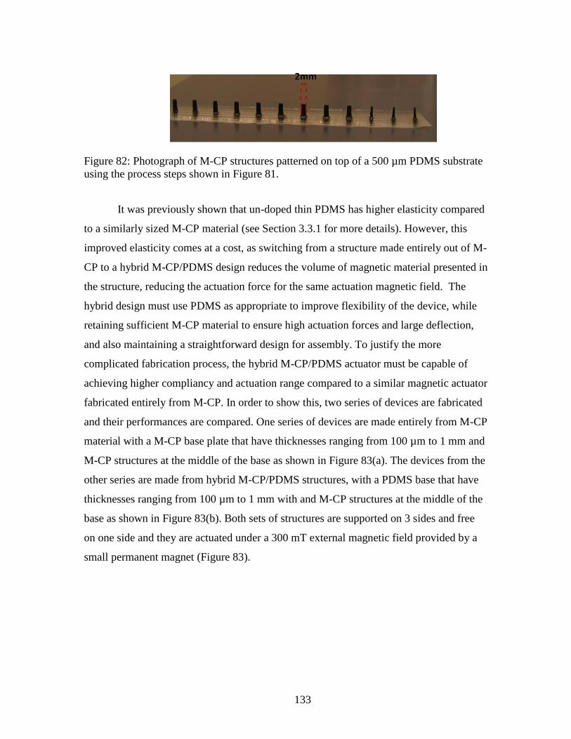
133
Figure 82: Photograph of M-CP structures patterned on top of a 500 µm PDMS substrate
using the process steps shown in Figure 81.
It was previously shown that un-doped thin PDMS has higher elasticity compared
to a similarly sized M-CP material (see Section 3.3.1 for more details). However, this
improved elasticity comes at a cost, as switching from a structure made entirely out of M-
CP to a hybrid M-CP/PDMS design reduces the volume of magnetic material presented in
the structure, reducing the actuation force for the same actuation magnetic field. The
hybrid design must use PDMS as appropriate to improve flexibility of the device, while
retaining sufficient M-CP material to ensure high actuation forces and large deflection,
and also maintaining a straightforward design for assembly. To justify the more
complicated fabrication process, the hybrid M-CP/PDMS actuator must be capable of
achieving higher compliancy and actuation range compared to a similar magnetic actuator
fabricated entirely from M-CP. In order to show this, two series of devices are fabricated
and their performances are compared. One series of devices are made entirely from M-CP
material with a M-CP base plate that have thicknesses ranging from 100 µm to 1 mm and
M-CP structures at the middle of the base as shown in Figure 83(a). The devices from the
other series are made from hybrid M-CP/PDMS structures, with a PDMS base that have
thicknesses ranging from 100 µm to 1 mm with and M-CP structures at the middle of the
base as shown in Figure 83(b). Both sets of structures are supported on 3 sides and free
on one side and they are actuated under a 300 mT external magnetic field provided by a
small permanent magnet (Figure 83).

134
Figure 83: Illustration of the actuators used for testing the effect of M-CP doping of the
base plate on the actuation range for two actuator types: (a) M-CP actuator with an M-CP
base plate and (b) hybrid M-CP/PDMS actuator with an un-doped PDMS base plate.
Actuation magnetic field = 300 mT. This diagram is for illustration purpose and does not
represent exact dimensional ratios.
Table 13 and Figure 84 show the average values for maximum actuation range
for the two types of actuators shown in Figure 83. All of these actuators are actuated
under a 300 mT external magnetic field.
Table 13: Actuation range for hybrid M-CP/PDMS actuators (Figure 83(a)) and M-CP
actuators (Figure 83(b)) with different thicknesses for the base plate ranging from 100
µm to 1 mm. Width of the base plate = 1 mm for all actuators. Three samples are measure
for each thickness.
Thickness of the
base plate (µm)
M-CP/PDMS hybrid actuator measurements
Average
M-CP actuator
measurements Average
Actuation range
improvement (%) 1 2 3 1 2 3
100 115 110 115 113 70 70 65 68 67
200 90 95 90 92 55 55 55 55 67
300 75 75 70 73 50 45 45 47 52
400 50 50 45 48 40 35 40 38 26
500 30 30 30 30 30 25 25 27 11
600 0 5 5 3 10 10 5 8 N/A
700 0 0 0 0 0 0 0 0 0
800 0 0 0 0 0 0 0 0 0
90 0 0 0 0 0 0 0 0 0
1000 0 0 0 0 0 0 0 0 0

135
As can be seen in Figure 84, using an un-doped base increases the actuation range
significantly for thin actuators. For a base with 100 µm thickness and 1 mm width, a 67%
increase in actuation range is achieved under the same applied magnetic field of 300 mT.
Increasing the thickness of the base reduces the flexibility in both cases. Figure 84 shows
the deflection data in Table 12 overlaid for both actuator designs. For thin base plates
with large membrane deflections, the increased flexibility of the base material using the
hybrid approach substantially increased the actuation range. For example, a 100-µm-
thick, un-doped base achieved a 67% increase in actuation range as compared to an M-CP
plate under the same 300 mT actuation. Hybrid actuators with thicker bases (between 600
and 800 µm) performed poorer than all M-CP structures, as the actuation force present
with the M-CP base is more important than the flexibility of the material for the low
deflections in this range.
Figure 84 : Actuation range for hybrid M-CP/PDMS actuators (Figure 83(a)) and M-CP
actuators (Figure 83(b)) at different base thicknesses. Width of the base plate = 1 mm for
all tested actuators. Vertical error bars represent one standard deviation over 3 samples at
each thickness.
Increasing the thickness of the base reduces the flexibility of the actuator in both
cases for the hybrid M-CP/PDMS actuator and the M-CP actuator.

136
Figure 85: An M-CP surface supported along three edges and free on the forth edge.
The deflection of a plate which is fully supported along three edges and free on
the fourth edge such as the actuator structure shown in Figure 85 cab be calculated using
the beam action analysis. The deflection of the free edge of the plate is found by using the
following formula:
(6.1)
where d is the maximum deflection of the plate on the midpoint of the free edge, E is
Young’s modulus, t is the plate’s thickness, I is the second moment of inertia (
q is the total load, a is the plate width, and b is the plate depth.
As shown in this formula, maximum deflection of such plate is inversely
proportional to its thickness (t) to the power of three. Therefore, as the membrane’s
thickness increases, the membrane actuation range rapidly decreases for both M-CP and
hybrid M-CP/PDMS membrane actuators. In addition, the above formula shows that a
membrane’s maximum deflection is also inversely proportional to the Young’s modulus
(E) of the plate. According to the Table 4 previously presented in Section 3.3.1, the un-
doped PDMS has a Young’s modulus of 0.522 MPa whereas the M-CP (PDMS doped
with 80 wt-% of rare-earth magnetic powder) has an increased Young’s modulus of 1.623
MPa. This increased Young’s modulus value of the M-CP explains the decreased
actuation range of the M-CP actuator when compared to the hybrid M-CP/PDMS
membrane actuator. The relationship between the reduced deflection range, and
membrane thickness predicted by this formula is in agreement with the experimental data
presented in Table 11 and Figure 80. The relationship between the M-CP membrane’s

137
flexibility and the Young’s modulus of the material is also as predicted. This provides
experimental verification of our model of M-CP actuator performance.
The hybrid M-CP/PDMS actuators are further characterized by a series of tests to
find the relationship between the actuator’s width and the actuation range of the hybrid
M-CP/PDMS actuators. As shown in Figure 86, hybrid M-CP/ PDMS actuators with
different widths ranging from 0.5 mm to 3 mm are used for these characterization tests.
The PMMA structures are fabricated using a CO2 Universal Laser System’s
VersaLASER©
laser ablation system to provide a testbed for the actuation.
Figure 86: Design of the test structure used to characterize the relationship between the
hybrid M-CP/PDMS actuator’s width and actuation range. This diagram is for illustration
purpose and is not to scale.
Figure 87 shows the relationship between the actuator’s width and the maximum
deflection range under a 300 mT actuation magnetic field using hybrid M-CP/PDMS
actuators.
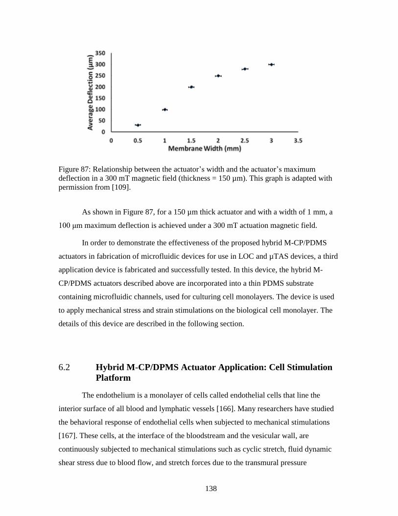
138
Figure 87: Relationship between the actuator’s width and the actuator’s maximum
deflection in a 300 mT magnetic field (thickness = 150 µm). This graph is adapted with
permission from [109].
As shown in Figure 87, for a 150 µm thick actuator and with a width of 1 mm, a
100 μm maximum deflection is achieved under a 300 mT actuation magnetic field.
In order to demonstrate the effectiveness of the proposed hybrid M-CP/PDMS
actuators in fabrication of microfluidic devices for use in LOC and µTAS devices, a third
application device is fabricated and successfully tested. In this device, the hybrid M-
CP/PDMS actuators described above are incorporated into a thin PDMS substrate
containing microfluidic channels, used for culturing cell monolayers. The device is used
to apply mechanical stress and strain stimulations on the biological cell monolayer. The
details of this device are described in the following section.
6.2 Hybrid M-CP/DPMS Actuator Application: Cell Stimulation
Platform
The endothelium is a monolayer of cells called endothelial cells that line the
interior surface of all blood and lymphatic vessels [166]. Many researchers have studied
the behavioral response of endothelial cells when subjected to mechanical stimulations
[167]. These cells, at the interface of the bloodstream and the vesicular wall, are
continuously subjected to mechanical stimulations such as cyclic stretch, fluid dynamic
shear stress due to blood flow, and stretch forces due to the transmural pressure

139
difference, in vivo [128,167]. It is widely recognized that these mechanical stimulations
play an important role in cardiovascular physiology and regulate vascular function
through a variety of mechanotransduction-related signaling pathways, which result in
altered cell shape, function, and migration [128,167–169]. The majority of previous
studies on these cells have focused on the effects of shear stress and stretch forces
separately. The accuracy of these tests are partly compromised and influenced by using
macro-scale instruments, in which mechanical stimulation cannot be easily controlled or
visualized [125,164,165]. Employing micro-scale devices provides a testing environment
that is closer to the in vivo micro-environment can provide valuable information on the
effect of these forces on the endothelial cells in micro-environments.
Microfluidic devices offer the desired micro-environment and new ways to study
the effect of the extra cellular stimuli on the spreading and migration of endothelial cells
with locally controlled mechanical and chemical stimuli [125,166]. Furthermore,
microfluidic channels make it possible to control the shape of the endothelial cells in the
absence of fluid flow by simply confining the cells, in order to determine the impact of
function properties on the shape of the cells [125]. Shear stress-induced elongation of
endothelial cells can trigger a wide range of functional responses. Therefore, control of
the cell shape using the relatively non-invasive technique of microfluidics confinement
has the potential benefit of altering endothelial cell shape without eliciting the other
responses, allowing for analysis that hasn’t been achievable with previous methods [125].
Although many studies have been previously done on the effect of mechanical
stimuli on cells [167–171], only a few previous works have been done on endothelial
cells [125]. Therefore, there is a great need for the development of microfluidic platforms
that provide simultaneous non-invasive control of the endothelial cell shape, as well as
controlled fluid flow mechanical shear stress and controlled tension/compression of the
endothelial cell culture surface. Such a combination of endothelial cell stimulations
would provide a valuable tool for vascular cell mechanics research [125].
In one study by Y. Kamotani et al. [172], a device is developed which consists of
24 miniature cell stretching chambers with flexible bottom membranes that are deformed
using the elements of a Braille display system. The tests performed on human dermal
140
microvascular endothelial cells (HDMECs) and mouse myogenic C2C12 cells showed
increasing degrees of alignment and elongation in response to cyclic stretch at increasing
frequencies of 0.2, 1, and 5 Hz, after 2, 4, and 12 hours. Strain amplitude is not
mentioned in the manuscript. The main limitation of this system is the lack of
microfluidic flow capabilities in the system [125].
In another study by Huh et al. [173], a bio-mimetic micro-systems is developed
which contains two parallel microfluidic channels separated by a 10 μm thick, porous,
flexible membrane made of PDMS. Human alveolar epithelial cells are cultured in one
side of the thin membrane, which is in contact with air. Human pulmonary microvascular
endothelial cells are cultured on the other sides of the thin membrane which is filled with
liquid. This structure mimics the air-liquid alveolar-capillary interface. The thin
membrane can be stretched cyclically using adjacent vacuum channels. The performance
of this micro-system is also limited by a lack of microfluidic flow, as well as the
relatively large size of the substrate sheet and supporting pneumatic systems [125].
Optical laser tweezers have also been used to locally apply mechanical tensile and
compressive forces on single cells trapped in wells in a microfluidic system [174].
However, these microfluidic systems are unable to apply simultaneous forces to multiple
cells or multilayers, and the applied forces are limited in magnitude [125].
There is a great need for the development of microfluidic platforms that provide
simultaneous non-invasive control of endothelial cell shape as well as simultaneous
controlled fluid flow, mechanical shear stress, and controlled tension/compression of the
endothelial cell culture surface. Such a combination of endothelial cell stimulations
would provide a valuable tool for vascular cell mechanics research [125]. The magnetic
composite polymer developed in this thesis offers numerous advantages as an actuation
mechanism for flexible and highly responsive microfluidic systems which require fast,
highly controlled, and localized actuations [12,125]. As such, a magnetically actuated
system using the M-CP technology developed in this thesis is an ideal candidate for
developing such a microfluidic platform.
The next section, Section 6.2.1, details the design and fabrication of the
microfluidic platform employing the new hybrid M-CP/PDMS actuator described in

141
Section 6.1, which provides bi-directional actuation for controlled stretch/compression of
endothelial cell culture. The experimental results are obtained by Dr. Gray and our
collaborator, Dr. Abdul Barakat at Ecole Polytechnique, France, using devices that are
designed jointly between the candidate, Dr. Gray, and Dr. Barakat; and fabricated
primarily by the candidate. Experimental setup and experimental results are discusses in
Section 6.2.2 and Section 6.3 respectively.
6.2.1 Design and Fabrication
Two different fabrication techniques are used for fabrication of the test platforms.
One uses an SU-8 mold, while the other uses a PMMA mold. In both cases, each of the
platforms contains a thin layer of PDMS substrate with a microfluidic channel and two
integrated M-CP actuators, which are micro-patterned on the PDMS surface. Each of the
two M-CP structures are located on one side of the microfluidic channel along the entire
length of the channel (Figure 89 and Figure 91). Each of the tested microfluidic platforms
are permanently mounted on a 1 mm thick PDMS spacer that allows bi-directional
actuation of the actuator, and are fixed inside a 100-mm-diameter Petri dish. Fixing the
platforms inside the Petri dish helps to prevent horizontal movement of the platform in
the Petri dish when subjected to an external actuation magnetic field. Without this step,
when the actuators are in an opposite polarity with the applied external magnetic field,
the repulsion force from the thicker M-CP actuators is great enough to repel an un-
mounted platform out of the Petri dish.
Figure 88 and Figure 90 illustrate the different steps involved in the fabrication of
each microfluidic platform using the SU-8 and PMMA molds, respectively[125], while
Figure 89 and Figure 91 illustrate the resulting platform in each case.

142
Figure 88: Fabrication process using the SU-8 molds: (a) SU-8 micro-mold is fabricated
following standard SU-8 fabrication techniques; (b) PDMS is molded, cured, and de-
molded; (c) M-CP is filled where actuators will be located, and the excess M-CP is
removed; device is cured at 80 °C for 2 hours and placed in a 1.8 ± 0.2 Tesla external
magnetic field after curing for permanent magnetization; (e) PDMS lid is bonded to the
chip using corona surface activation technique.
Figure 89: (a) schematic and (b) photograph of the device fabricated using SU-8 mold.

143
Figure 90: Fabrication process using the PMMA molds: (a) PMMA micro-mold is
fabricated using multi-step laser ablation to achieve multi-level mold; (b) M-CP is
applied where actuators will be; (c) excess M-CP is scraped off, and M-CP is cured; (d)
PDMS is molded; (e) PDMS is cured, and de-mold; device is placed in a 1.8 ± 0.2 Tesla
external magnetic field after curing for permanent magnetization; (f) PDMS lid is bonded
to the chip using corona surface activation technique.
Figure 91: (a) schematic and (b) photograph of the device fabricated using PMMA multi-
level mold and modified soft-lithography technique.

144
Both fabrication techniques are employed to achieve different size ranges for the
microfluidic channel’s width and depth, as well as the M-CP structure’s width and height,
and the distance between the microfluidic channel edges and the edges of the M-CP
structures. Table 14 shows the dimensional ranges for both the SU-8 molded devices and
the PMMA molded devices. Three different channel lengths are used for both types of
molded devices: 1 cm, 2 cm, and 3 cm. The SU-8 molds are fabricated following standard
SU-8 fabrication techniques in a single SU-8 layer for simplicity, while the PMMA
molds are fabricated as two-level molds. The two level PMMA mold helps to further
increase the thicknesses of the M-CP actuator and achieve actuator heights that are much
larger than the microfluidic channel depths. This is not the case for the single layer SU-8
molds, which results in the same depth for the channel and the M-CP structures.
The double layer PMMA mold and thicker M-CP structures help to increase the
magnetic attraction/repulsion of the actuators, as compared to the platforms fabricated
using SU-8 mold. However, as shown in Figure 92 it is noted that using these methods
for lid attachment are not optimal; a gap between the lid and the device surface in the area
between the M-CP actuators, and over the microfluidic channel, often results due to either
an overfilled M-CP reservoir and/or difficulty in manually sealing the lid close to the
channel. It is estimated that a gap of up to 70 μm may exists between the device surface
and the lid.

145
Figure 92: Illustration of (a) and (b) ideal case for attaching the lid to the microfluidic
base, and (c) and (d) a small gap, up to approximately 70 µm, that may exist between the
lid and the base due to either (c) an overfilled M-CP reservoir in case of the devices made
using SU-8 molds, or (d) difficulty in manually aligning and sealing the lid close to the
channel in the case of devices fabricated using PMMA molds.
Table 14: This table shows the dimensional properties of fabricated cell stimulation
platforms using the SU-8 Molds and PMMA molds. This data is reprinted with
permission from [125], © 2014 IEEE.
Type of Master Mold
Employed
SU-8 molds PMMA molds
channel widths 50 – 500 μm 100 – 200 μm
channel depth 60 μm 160 μm
actuator width 2-4 mm 2 mm
actuator height 60 μm 400 – 500 μm
gap between actuator and channel 100 μm 1 – 2 mm
6.2.2 Experimental Setup
A similar controlled actuation system to the one used for valve actuation (Section
4.2) is used for testing the hybrid M-CP/PDMS actuators. As shown in Figure 94, a small
permanent magnet is mounted on a miniature linear motor. For proof-of-concept testing,

146
a testing apparatus with a permanent magnet attached to a linear actuator (L12-P-50,
Fergelli, Inc) is employed. Based on the polarity of the permanent magnet and the
actuators on the platform, the permanent magnet can provide either tension or
compression on the microfluidic channel surface. The use of permanently magnetized M-
CP in the actuation fabrication allows the tension and compression force that can be
reversed using the same miniature linear motor by using two permanent magnets with
opposite polarities as shown in Figure 95. The magnetic actuators are attracted toward the
bottom of the Petri dish, resulting in a compressive force on the microfluidic channel
bottom surface (Figure 93).
Figure 93: Illustration shown endothelial cells grown in microfluidic channels in devices
made using (a) SU-8 molds and (b) PMMA mold.
The actuation magnetic field is measured to be approximately 50 mT at the
microfluidic channel, providing 1 mm deflection, which is equivalent to the height of the
spacers used in the tests. The platforms are then mounted under an inverted microscope
equipped with a CCD camera for cell migration/elongation monitoring.

147
Figure 94: Photograph of the linear actuator, L12-P-50, Fergelli, Inc, used to move the
permanent magnet underneath the platform.
Figure 95: Using two permanent magnets with opposite polarities in the actuation
mechanism can provide bi-directional actuation.
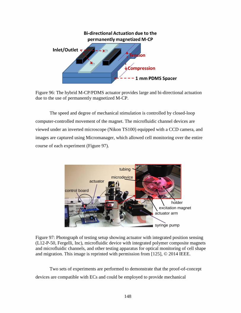
148
Figure 96: The hybrid M-CP/PDMS actuator provides large and bi-directional actuation
due to the use of permanently magnetized M-CP.
The speed and degree of mechanical stimulation is controlled by closed-loop
computer-controlled movement of the magnet. The microfluidic channel devices are
viewed under an inverted microscope (Nikon TS100) equipped with a CCD camera, and
images are captured using Micromanager, which allowed cell monitoring over the entire
course of each experiment (Figure 97).
Figure 97: Photograph of testing setup showing actuator with integrated position sensing
(L12-P-50, Fergelli, Inc), microfluidic device with integrated polymer composite magnets
and microfluidic channels, and other testing apparatus for optical monitoring of cell shape
and migration. This image is reprinted with permission from [125], © 2014 IEEE.
Two sets of experiments are performed to demonstrate that the proof-of-concept
devices are compatible with ECs and could be employed to provide mechanical
actuator
control board
syringe pump
microdevice
holder
actuator arm
tubing
excitation magnet

149
stimulation, compression/tension, potentially simultaneously with other stimuli such as
microfluidic channel confinement and/or fluid flow shear stress.
In the first set of test, the endothelial cells are cultured on the bottom surface of
the microfluidic channel without covering the channels and without providing fluid flow.
In these tests, cells are viewed on the surface of the PDMS in the gap between the
microfluidic channel and the M-CP actuators rather than within a microfluidic channel.
Devices fabricated with PMMA molds are used to ensure a wide gap. A 50 mT magnetic
field at 1 Hz is applied to compress BAECs grown on the bottom surface of the channel
for a 2-hour period. Images are taken every 20 minutes. Photographs of control (un-
stimulated) cells are also taken over a 2-hour period.
In the second set of tests, the microfluidic channels are enclosed with lid to
provide fluid flow conditions. In these tests, cells are subject to both microfluidic
channel confinement and flow using microfluidic channels approximately 60 μm deep,
150 μm wide, and 2 cm long, using devices that are fabricated employing SU-8 molds. A
40 µL/min flow rate of cell culture medium (corresponding to a minimum of 20 dyne/cm2
fluid flow shear stress on the BAECs) is applied to the cells for 2 hours without magnetic
actuation, followed by 2 hours of flow and magnetic actuation at a frequency of 1 Hz.
The magnetic actuation frequency is produced by the linear actuator providing
and removing the magnet beneath the microfluidic devices. A completed cycle consisted
of the magnet starting from home position away from the microfluidic device, extending
to beneath the microfluidic device thus actuating its M-CP magnets, and then returning to
home position, with the process being immediately repeated.
6.3 Experimental Results
Analysis of time-lapse movies from both sets of experiments demonstrates the
feasibility of the actuator, both with and without fluid flow. The results indicate that the
instrument is indeed compatible with bovine aortic endothelial cells (BAECs) and can be
employed to provide simultaneous microfluidic channel confinement, cell
stretch/compression, and microfluidic flow (Figure 98 and Figure 99). Furthermore, as

150
indicated by the circled cells in each photograph, it is possible to track individual cell
migration over time (Figure 99) using the instrument and microscope set-up shown in
Figure 97.
Figure 98: Stills from time lapse movie showing cell movement over 2 hours for no-
stretch (a and b) and stretch (c and d) under enclosed microfluidic channel and flow (40
µl/min) conditions. Channel depth is approximately 60 µm. Individual cells (circled) can
be monitored over time. This image is reprinted with permission from [125], © 2014
IEEE.
Figure 99: Stills from time lapse movie showing cell movement for stretch (140-180
minutes) and no-stretch (180-220 minutes) under open channel, no flow conditions.
Individual cells (circled) can be monitored over time. This image is reprinted with
permission from [125], © 2014 IEEE.
(a) (b)
(c) (d)
150 µm
microchannel
magnetic polymer
magnetic polymer
(b) (c)(a)
180 min 220 min140 min

151
6.4 Summary and Conclusion
In this chapter, a hybrid M-CP/PDMS actuator is developed to achieve large and
bi-directional surface actuation for microfluidic devices and systems. It is demonstrated
that the hybrid actuator can achieve increased actuation range and flexibility while
providing optical transparency for easier integration and optical monitoring and detection
of biological cells grown inside the microfluidic system. To further characterize the
performance of the hybrid M-CP/PDMS actuator, a cell stimulation platform is developed
and experiments are performed to show that the fabricated devices are compatible with
endothelial cells and could be used to provide mechanical stimulation potentially
simultaneously with other stimuli, such as microfluidic channel confinement and/or fluid
flow shear stress. It is successfully demonstrated that these platforms are capable of
creating simultaneous stretch/compression forces and fluid flow, while providing the
possibility of contentiously monitoring of the cells alignment and migration. This
application gives an example of the wide variety of applications in microfluidics that can
benefit from magnetic actuation in general, and actuators based on the M-CP investigated
in this thesis specifically.
6.5 Related Publications
The results of this work have been presented at the following peer reviewed
conferences:
1. Gray, B. L. Rahbar, M., Babataheri, A., and Barakat, A., “Microinstrument
for Optical Monitoring of Endothelial Cell Migration under Controlled
Tension/Compression Via Integrated Magnetic Composite Polymer
Actuation,” (IEEE-NANO) 14th IEEE International Conference on
Nanotechnology, 2014.
2. Rahbar, M., Seyfollahi, S., Khosla, A., Shannon, L., Gray, B. L.,
“Fabrication Process for Electromagnetic Actuators Compatible with Polymer
Based Microfluidic Devices,” ECS Transactions, the Electrochemical Society,
41, 2012.

152
Chapter 7 - Summary of Thesis Contributions
This thesis presents novel magnetic composite polymer actuators for microfluidics
systems, offering significant improvement in performance and ease of integration over
existing polymer magnetic actuators.
The contributions to the microfluidic instrumentation field can be broken down
into the following:
Detailed characterization of the physical and functional properties of a
novel magnetic composite polymer (M-CP) material suitable for
microfluidic actuators, as well as development of guidelines for the use of
the material in the development of magnetically-actuated polymer
microfluidic systems.
Design, fabrication, and characterization of novel magnetic microfluidic
actuators employing the new M-CP material, demonstrating the robustness
and versatility of the polymer material for key actuator types, the ease of
integration of M-CP actuators with existing polymer processes, and
demonstration of consistently improved performance over existing
actuator designs and techniques.
Development of new fabrication processes specific for the new M-CP
material, focusing on straightforward techniques that are low-cost, scalable
for volume production, and that allow for fabrication of microfluidic
actuators and other structures not achievable with pre-existing processes.
These contributions are achieved by meeting the following objectives:
Material development
Technology development
Application outcome: Development and performance characterization of rare-
earth all-polymer actuators
o Artificial cilia actuator as a microfluidic cilia mixer
o Flap-based actuator as a microfluidic valve
o Hybrid M-CP/PDMS actuator as a microfluidic actuator for applying
extracellular stimulation on biological cell monolayer
Detailed descriptions of how these specific objectives are met are presented in
Sections 3-6.
The main results of this thesis have been published in three journal papers and
four conference papers that are directly related to the development of M-CP actuators
described in this thesis. The initial results of work on the development of ultra-high

153
aspect-ratio artificial cilia actuators and the microfluidic mixers based on the cilia
actuators were presented at SPIE MOEMS-MEMS and awarded “The Best Student Paper
Award in the MOEMS-MEMS symposium” at SPIE MOEMS-MEMS, International
Society for Optics and Photonics, 2014. This award covered eleven 2014 SPIE Photonics
West conferences, with each conference supplying up to two student paper entries.
Expanded results of this work were published in the Journal of Micromechanics and
Microengineering (JMM); this paper was selected as a JMM highlight for the year 2014.
The initial work on the development of flap-based M-CP actuators was presented at the
MicroTAS 2014 conference. It was selected for oral presentation, with less than 10% of
the submitted papers accepted for oral presentation. A journal paper containing additional
work on the M-CP microfluidic valves based on the flap actuators was recently published
in the Journal of Micromechanics and Microengineering in 2016. A complete list of
academic publications achieved during the period of the thesis work is presented in
Section 7.4, with academic publications directly related to the material presented in the
thesis indicated by an asterisk, “*”.
7.1 Material Development
To address limitations in the employment of rare-earth magnetic materials in the
development of highly effective magnetic actuators, the Micro-Instrumentation
Laboratory (µIL) at Simon Fraser University has developed effective and highly
magnetic composite polymers (M-CP), using neodymium-based rare-earth permanently
magnetic powders [85,175–177]. Throughout the research work presented in this thesis,
this novel material is used for the first time for development of several key types of all-
polymer magnetic actuators. To effectively use this new material, the magnetic and
mechanical properties of this new material are characterized in detail. The results of these
characterizations are used for design and development of several key magnetic
microfluidic actuators. As part of the long term goals of the µROAMS project (see
Section 1.1), these results will be used for further optimization of the next generation of
magnetically actuated components and other magnetic polymer devices.

154
In previously reported work on magnetically actuated components for micro-
electro-mechanical systems (MEMS) and microfluidics, relatively weak soft-magnetic
iron-based materials are typically used. These magnetic materials suffer from several key
limitations, including limitation to uni-directional actuation (attraction but not repulsion),
requirements of relatively large magnetic fields for actuation, and the creation of
relatively small displacements. Permanently magnetized hard-magnetic materials can be
used to alleviate these limitations. Neodymium rare-earth magnetic materials in particular
are capable of much higher magnetic forces. Existing designs that use rare-earth magnets
typically involve discrete magnets (i.e., small separately-fabricated magnets that must be
embedded or attached to the moving structure), which are difficult to integrate into
systems in the micro-scale and are prone to physical failure. Magnetic powders can be
combined with structural polymer materials to form composite polymers. However, the
majority of previously published works utilizing magnetic composite polymers are based
on combining iron-based soft-magnetic nano- or micro-particles. The use of hard-
magnetic rare-earth micro- and nano-particles in magnetic composite polymers is far less
reported by previous researchers. This is mainly due to the fact that soft-magnetic
particles are readily available in a wide range of compositions and sizes, are easy to
process into magnetic composite polymers, and are low cost [12].
The rare-earth hard-magnetic powder, (Nd0.7Ce0.3)10.5 Fe83.9B5.6, used in the newly
developed magnetic composite polymer (M-CP) employed throughout this thesis results
in stronger magnets with higher magnetic saturation compared to the more common Fe-
based soft-magnetic materials, with four times the magnetic remanence of isotropic
ferrite materials and two times the remanence of anisotropic ferrite powders. Structures
made with this M-CP can be actuated in much smaller magnetic fields and achieve much
higher actuator displacement than the same structures made with soft-magnetic powder.
The capability of bi-directional actuation is another key advantage of the hard-magnetic
M-CP used in this thesis, as compared to the soft-magnetic materials previously used in
microfluidic actuators. Furthermore, the composite polymer in this work overcomes the
difficulties in fabrication, assembly, and weak adhesion associated with other methods of
integrating hard magnetic materials into polymer systems, resulting in creation of highly
flexible actuators with strong actuation force.
155
7.2 Technology Development
In this research work, several novel fabrication and integration techniques are
developed in order facilitate effective use of the newly developed M-CP material in
development of new magnetic actuators for microfluidic applications. These fabrication
and integration techniques are relatively low cost, straightforward, and compatible with
existing polymer fabrication techniques used for other structures on the device. These
techniques allow for the creation of arrays of vastly different types of key M-CP actuators
on the same polymer-based microfluidic platform.
Various methods have been previously reported for micro-machining magnetic
materials for use in MEMS and microfluidics but these attempts face difficulties in
integration of magnetic materials into the fabrication of the device [12]. To allow for
more straightforward integration of hard-magnetic material into polymer-based
microfluidic actuators and development of higher performing actuators, the contribution
of this thesis includes development of new fabrication techniques for actuators based on
our magnetic composite polymer using neodymium-based hard-magnetic powder:
A novel fabrication technique for creation of ultra-high aspect-ratio, highly
flexible M-CP artificial cilia with controlled positioning by using poly(ethylene
glycol) (PEG) as a sacrificial mold. The use of PEG as a sacrificial mold for
micro-fabrication purposes in micro-electro-mechanical systems (MEMS) and
microfluidics has not been previously reported in any literature, and is developed
and presented as part of this research work for the first time to the best of the
author’s knowledge.
Screen printing of magnetic composite polymers using shadow masks for
patterning of a thin layer of M-CP on the surface of un-doped PDMS to realize a
wide variety of structures and key actuator components.
A modified soft lithography technique for the creation of hybrid M-CP/PDMS
systems. This fabrication technique is adapted for M-CP from a similar technique
introduced by Khosla et al. [24] which was used for creating conductive
composite polymers structures on PDMS substrates.
The development of these new fabrication techniques allows the use of the newly
developed M-CP material for easy development of a wide variety of actuator and other
structures. These fabrication techniques are relative straightforward and low cost, and are
compatible with each other and with other existing polymer fabrication techniques and

156
materials. This allows for easy integration with other structures on a polymer microfluidic
system, and is well suited for volume production.
7.3 Application Outcome: Development and Performance
Characterization of Key Rare-earth All-Polymer Actuators
Development of effective polymeric magnetic actuators that employ hard-
permanently-magnetic materials, and that can be more easily integrated with other
polymeric components in a microfluidic system, are essential to harness the full benefits
of hard-magnetic materials for microfluidic applications. The final key contribution of
this thesis is the development of key magnetic actuators using the new M-CP material
and fabrication techniques developed in this work: cilia actuators, flap-based actuators,
and hybrid M-CP/PDMS actuators for surface deflection. These actuator types (cilia, flap,
and hybrid M-CP/PDMS actuators) appear commonly in microfluidic systems, as they
can be employed for many different applications. However, by using the results of the
materials and technological development outcomes discussed in the previous two
sections, significantly improved actuators of each of these key types are developed as part
of the thesis, and are shown to have improved performance in various microfluidic
devices: a cilia mixer, a flap-based valve, and a microfluidic actuator for applying
extracellular stimulation on biological cell monolayer. The performance of each of these
microfluidic devices is compared with the performance of pre-existing devices to
demonstrate the great enhancements that these newly developed devices can offer to the
field of MEMS and microfluidics. All three types of magnetic actuators employ
materials, fabrication techniques, and actuation mechanisms which are compatible with
each other and with previously existing polymer microfluidic structures, reducing the
fabrication and integration complexity for large arrays of microfluidic components in
complex microfluidic systems.

157
7.4 List of Publications
Publications directly related to the thesis proposal are identified with an asterisk, “*”.
1. *Rahbar, M., Shannon, L., Gray, B. L., “Design, fabrication and characterization
of an arrayable all-polymer microfluidic valve employing highly magnetic rare-
earth composite polymer,” Journal of Micomechanics and Microengineering, 26,
2016.
2. *Tseng, H. Y., Malfesi, S., Tehranchi, N., Rahbar, M., Jones, J., Gray, B. L.,
“On-Board array for multiplexed semi-active cooling rate controlled
cryopreservation of living cells,” Journal of Medical and Biological Engineering,
Issue: The 37th Canadian Medical and Biological Engineering Conference, 26,
206-213, 2016.
3. *Rahbar, M., Shannon, L., and Gray, B. L., “Arrayable Microfluidic Valves
Based on Rare Earth Permanently Magnetic Polymer for Use in Microfluidic
Flow Switching,” MicroTAS proceeding, 2014. (Oral presentation at
MicroTAS conference. Less than 10% of the submitted papers were accepted for
oral presentation).
4. *Gray, B. L. Rahbar, M., Babataheri, A., and Barakat, A., “Microinstrument for
Optical Monitoring of Endothelial Cell Migration under Controlled
Tension/Compression Via Integrated Magnetic Composite Polymer Actuation,”
(IEEE-NANO) 14th IEEE International Conference on Nanotechnology, 2014.
(Oral presentation at MicroTAS conference.)
5. *Rahbar, M., Shannon, L., and Gray, B. L., “Microfluidic active mixers
employing ultra-high aspect-ratio rare-earth magnetic nano-composite polymer
artificial cilia,” Journal of Micromechanics and Microengineering, 24, 025003,
2014. (Selected for the JMM highlights of the year 2014)
6. *Rahbar, M., Tseng, H. Y., and Gray, B. L., “High-aspect ratio magnetic
nanocomposite polymer cilium,” Proc. SPIE MOEMS-MEMS, International
Society for Optics and Photonics, 89760D-89760D-9, 2014. (Awarded: The Best
Student Paper Award in the MOEMS-MEMS symposium)
7. Rahbar, M., and B. L. Gray, “Flexible touchpads based on inductive sensors
using embedded conductive composite polymer,” Proc. SPIE 9060, Nanosensors,
Biosensors, and Info-Tech Sensors and Systems, 2014.

158
8. *Rahbar, M., Seyfollahi, S., Khosla, A., Shannon, L., Gray, B. L., “Fabrication
Process for Electromagnetic Actuators Compatible with Polymer Based
Microfluidic Devices,” ECS Transactions, 41, 2012.
9. Chinna, S., Bajwa, A., Rahbar, M., Kaleibar, A. A., Li, P., and Parameswaran,
M., “Ultra low cost PMMA microfluidic devices fabrication and electrophoretic
pinch injection,” Journal of Medical and Biological Engineering, 31, 105-110,
2011.
10. Bajwa, A., Chhina, S. K., Rahbar, M., Bahreyni, B. and Parameswaran, M.,
“Explorations in electrical domain determination of mobile liquid sample
concentration in a PMMA microfluidic device,” Proceedings of 23rd Canadian
Congress of Applied Mechanics (CANCAM ’11), Invited in BioMEMS/NEMS:
Design, Fabrication and Application, 2011.
159
Chapter 8 - Conclusion and Future Work
This thesis presents new all-polymer magnetic actuators employing neodymium-
based rare-earth permanently magnetic composite polymer (M-CP) for integration into
complex, all-polymer microfluidic systems offering significant improvement in
performance and ease of integration over existing polymer magnetic actuators. The
improved performance and integration of the all-polymer magnetic actuators presented in
this thesis are achieved by two means: use of a new M-CP and use of newly developed
fabrication techniques. Mechanical and magnetic characterization of the newly developed
M-CP material is presented with a view toward employing the M-CP material for
improved actuation techniques and structural compatibility with other devices. Three new
fabrication techniques are developed that rely on the unique properties and polymer
compatibility of the developed material, and are in turn employed for the design and
fabrication of various types of new M-CP actuators based on commonly employed
actuator types. All fabrication processes are designed to be highly compatible with other
commonly used microfluidic materials and fabrication techniques, and include: a
modified soft lithography technique for the creation of hybrid M-CP/PDMS systems; a
screen printing technique using shadow masks for the creation of thin-layer-M-CP/PDMS
hybrid systems; and a novel fabrication technique for creation of bio-inspired, ultra-high
aspect-ratio, highly flexible M-CP artificial cilia using poly(ethylene glycol) (PEG) as a
sacrificial mold. Results of the material characterizations and the newly developed,
compatible fabrication techniques are used to develop three types of magnetic actuators
based on three key actuator types common in microfluidics: ultra-high aspect-ratio
artificial cilia actuators; flap-based magnetic actuators; and hybrid M-CP/PDMS
actuators for large and bi-directional surface deflection. The efficiency and performance
of each of the newly developed microfluidic magnetic actuators are investigated in the
context of commonly used and highly in demand microfluidic applications: a microfluidic
mixer, a microfluidic valve, and a microfluidic platform for cell stimulations. Each of
these devices shows high performance in their respective fields when compared to
existing devices for these applications.

160
The M-CP cilia mixer presented in this thesis is one of the highest performing
cilia-based microfluidic actuators designs reported in the literature [19,84,106,128]. It can
be fabricated in extreme aspect-ratios, providing far more design flexibility than
previously available artificial cilia-based actuators. The high flexibility of the cilia
structures and highly magnetic rare-earth composite polymer material provide greatly
enhanced actuation and mixing performance for the cilia-based mixer developed in this
thesis. As a result of both the high magnetic forces and flexibility of the magnetic
composite polymer, the cilia actuator presented in this thesis can be effectively actuated
using very small magnetic field of 7 mT provided by a miniature electromagnet. The
highly flexible M-CP material allows the use of a physically smaller electromagnet for
actuation, easing integration of the magnet into the design. Furthermore, using a less
powerful electromagnet reduces the cross-talk between actuators, allowing for the cilia
array density to be increased.
A similar degree of improvement is seen for the flap-based actuators, where a
magnetic field of 80 mT is used for flap-based valve actuation, as compared to much
larger magnetic fields used for the actuation of other polymeric membrane- or flap-type
actuators in the literature [140,156]. The all-polymeric magnetic flap actuator, with a two
level step shaped design, provides much higher actuation force for a given magnetic field
than previous designs, while the use of permanently magnetized material allows for bi-
directional actuation, improves actuation speed, and eliminates some actuation failures.
The use of this flap-based actuator in the microfluidic valve designed in this work
provides a highly effective valve structure that shows high performance as both on/off
valve and flow switching element for continuous flow. Additionally, the novel use of
magnetic composite polymer in the valve seat, in addition to the valve flap, provides a
latching mechanism and enhances valve performance. This is achieved using materials
and production processes that are compatible with the other elements of the µROAMS
platform, as well as other polymeric microfluidic devices.
Large force, large stroke hybrid M-CP/PDMS hybrid actuators for surface
deflection are capable of providing bi-directional actuation, which allow development of
a device that can apply both tensile and compressive forces on biological cells. Actuation
of the surface can be applied cyclically, with the transparent PDMS material allowing for

161
continuous optical monitoring of the cell monolayer’s response to extracellular
stimulations. The M-CP polymer material is shown to be bio-compatible with monolayers
of endothelial cells grown in microfluidic channels, under both flow and no-flow
conditions.
Although the preliminary results have already been presented for the work on
valve actuation mechanism and the cell stimulation platform, work is continuing in
further characterization of these actuators. Future work will include replacement of the
miniature linear motor with an electromagnet-based mechanism, where each actuator in
an array is under separate electromagnetic control that will significantly reduce the area
and power footprint of the actuation mechanism and will be more suitable for integration
of a large number of these actuators.
For the cilia mixer, all of the presented characterization test results are obtained
using two-dimensional microscopy images due to the limitation of available imaging
equipment. As a result, the efficiency of mixing in vertical direction is not fully analyzed.
This aspect of the mixing performance will be explored in future work.
Further theoretical studies and characterization of microfluidic structures using
multiphysics simulation software tools such as COMSOL and ANSYS may result in
better optimization of the next generation of M-CP actuators, as will applying detailed
models for the behavior of particles and fluids at the microfluidic level. For example, the
Scallop theorem [178] for the motion of objects in fluids with low Reynolds number may
help with the design and development of new types of actuators under laminar fluid
flows.
Also, collaborative work with other researchers in µIL and MIL will be continued
on the integration of these actuators with other sensor and actuator components currently
under development at Microinstrumentation Laboratory towards the long term goal of
achieving a fully functional generic microfluidic platform compatible with many
application areas.
In summary, this thesis provides a foundation for future development of various
types of all-polymer magnetic actuators using M-CP that can be integrated with complex
polymer microfluidic systems and devices.

162
References
[1] Rivet C, Lee H, Hirsch A, Hamilton S and Lu H 2011 Microfluidics for medical
diagnostics and biosensors Chem. Eng. Sci. 66 1490–507
[2] Mastrangelo C H, Man P F and Webster J R 2000 Polymer-based micromachining
for microfluidic devices
[3] Rhee M 2009 Advanced Components of Microfluidic Systems for Bioanalytical
Applications (ProQuest)
[4] Ho B and Kjeang E 2011 Microfluidic fuel cell systems Cent. Eur. J. Eng. 1 123–
31
[5] Erik Kjeang N D 2009 Microfluidic fuel cells: A review J. Power Sources 353–69
[6] Paik P Y, Pamula V K and Chakrabarty K 2008 A Digital-Microfluidic Approach
to Chip Cooling IEEE Des. Test Comput. 25 372–81
[7] Bixler G D and Bhushan B 2013 Fluid Drag Reduction with Shark-Skin Riblet
Inspired Microstructured Surfaces Adv. Funct. Mater. 23 4507–28
[8] Rahbar M 2010 PMMA microfluidics technology: development and
characterization Thesis (Applied Science: School of Engineering Science)
[9] Fu Y 2005 Design of a hybrid magnetic and piezoelectric polymer microactuator
Thesis (HAWTHORN, VICTORIA AUSTRALIA: SWINBURNE UNIVERSITY
OF TECHNOLOGY)
[10] Yun K-S and Yoon E 2008 Fabrication of complex multilevel microchannels in
PDMS by using three-dimensional photoresist masters Lab. Chip 8 245–50
[11] Nguyen N T and Wereley S T 2006 Integrated microsystem series (Boston: Artech
House)
[12] Gray B L 2014 A Review of Magnetic Composite Polymers Applied to
Microfluidic Devices J. Electrochem. Soc. 161 B3173–83
[13] Zheng P 2004 Magnetic MEMS and its applications Thesis (Florida State
University)
[14] Liu C and Yi Y W 1999 Micromachined magnetic actuators using electroplated
permalloy IEEE Transducers Magn. 35 10
[15] Ganguly R and Puri I K 2010 Microfluidic transport in magnetic MEMS and
bioMEMS Wiley Interdiscip. Rev. Nanomed. Nanobiotechnol. 2 382–99
[16] Pamme N 2006 Magnetism and microfluidics Lab. Chip 6 24–38

163
[17] Ziliang Cai J X 2015 A magnetically actuated valve for centrifugal microfluidic
applications Sens. Actuators B Chem. 206 22–29
[18] Oh K W and Ahn C H 2006 A review of microvalves J. Micromechanics
Microengineering 16 R13
[19] Mohammadreza Riahi E A 2012 Fabrication of a 3D active mixer based on
deformable Fe-doped PDMS cones with magnetic actuation J. Micromechanics
Microengineering 22 115001
[20] Huh Y S, Choi J H, Huh K A K, Kim K A, Park T J, Hong Y K, Kim D H, Hong
W H and Lee S Y 2007 Microfluidic cell disruption system employing a
magnetically actuated diaphragm Electrophoresis 28 4748–57
[21] Capanu M, Boyd I J G and Hesketh P J 2000 Design, fabrication, and testing of a
bistable electromagnetically actuated microvalve J. Microelectromechanical Syst.
9 181–9
[22] Lee C-Y and Chen Z-H 2009 Valveless impedance micropump with integrated
magnetic diaphragm Biomed. Microdevices 12 197–205
[23] Sutanto J, Hesketh P J and Berthelot Y H 2006 Design, microfabrication and
testing of a CMOS compatible bistable electromagnetic microvalve with
latching/unlatching mechanism on a single wafer J. Micromechanics
Microengineering 16 266
[24] Khosla A 2011 Micropatternable multifunctional nanocomposite polymers for
flexible soft MEMS applications Thesis (Applied Science: School of Engineering
Science)
[25] Li H 2014 Fabrication ofmagnetic two-dimentional and three-dimentional
microstructures for microfluidics and microrobotics applications Thesis
[26] Whitesides G M 2006 The origins and the future of microfluidics Nature 442 368–
73
[27] Fan Y 2015 Low-cost polymer-based microfluidic systems
[28] Barry R and Ivanov D 2004 Microfluidics in biotechnology J. Nanobiotechnology
2 2
[29] Hsu Y-C and Chen T-Y 2007 Applying Taguchi methods for solvent-assisted
PMMA bonding technique for static and dynamic μ-TAS devices Biomed.
Microdevices 9 513–22
[30] Martin P M, Matson D W, Bennett W D and Hammerstrom D J 1998 Fabrication
of plastic microfluidic components vol 3515pp 172–6

164
[31] Li P C H 2005 Microfluidic Lab-on-a-Chip for Chemical and Biological Analysis
and Discovery (CRC Press)
[32] Erickson D and Li D 2004 Integrated microfluidic devices Anal. Chim. Acta 507
11–26
[33] Saliterman S S 2006 Fundamentals of BioMEMS and Medical Microdevices
(Hoboken, NJ : Bellingham, Wash: SPIE Publications)
[34] Halldorsson S, Lucumi E, Gómez-Sjöberg R and Fleming R M T 2015
Advantages and challenges of microfluidic cell culture in polydimethylsiloxane
devices Biosens. Bioelectron. 63 218–31
[35] Mark D, Haeberle S, Roth G, Stetten F von and Zengerle R 2010 Microfluidic lab-
on-a-chip platforms: requirements, characteristics and applications Chem. Soc.
Rev. 39 1153–82
[36] Walker G M and Beebe D J 2002 A passive pumping method for microfluidic
devices Lab. Chip 2 131–4
[37] Resto P J, Mogen B J, Berthier E and Williams J C 2010 An automated
microdroplet passive pumping platform for high-speed and packeted microfluidic
flow applications Lab. Chip 10 23–6
[38] Jeong G S, Oh J, Kim S B, Dokmeci M R, Bae H, Lee S-H and Khademhosseini A
2014 Siphon-driven microfluidic passive pump with a yarn flow resistance
controller Lab. Chip 14 4213–9
[39] Lynn N S and Dandy D S 2009 Passive microfluidic pumping using coupled
capillary/evaporation effects Lab. Chip 9 3422–9
[40] Jeon N L, Chiu D T, Wargo C J, Wu H, Choi I S, Anderson J R and Whitesides G
M 2002 Microfluidics Section: Design and Fabrication of Integrated Passive
Valves and Pumps for Flexible Polymer 3-Dimensional Microfluidic Systems
Biomed. Microdevices 4 117–21
[41] Feng Y, Zhou Z, Ye X and Xiong J 2003 Passive valves based on hydrophobic
microfluidics Sens. Actuators Phys. 108 138–43
[42] Kim J, Kido H, Rangel R H and Madou M J 2008 Passive flow switching valves
on a centrifugal microfluidic platform Sens. Actuators B Chem. 128 613–21
[43] Seker E, Leslie D C, Haj-Hariri H, Landers J P, Utz M and Begley M R 2009
Nonlinear pressure-flow relationships for passive microfluidic valves Lab. Chip 9
2691–7
[44] Song Y S 2012 A passive microfluidic valve fabricated from a hydrogel filled
with carbon nanotubes Carbon 50 1417–21

165
[45] Hong C-C, Choi J-W and Ahn C H 2004 A novel in-plane passive microfluidic
mixer with modified Tesla structures Lab. Chip 4 109–13
[46] Lin Y-C, Chung Y-C and Wu C-Y 2006 Mixing enhancement of the passive
microfluidic mixer with J-shaped baffles in the tee channel Biomed. Microdevices
9 215–21
[47] Nguyen T N T, Kim M-C, Park J-S and Lee N-E 2008 An effective passive
microfluidic mixer utilizing chaotic advection Sens. Actuators B Chem. 132 172–
81
[48] Mansur E A, YE M, WANG Y and DAI Y 2008 A State-of-the-Art Review of
Mixing in Microfluidic Mixers Chin. J. Chem. Eng. 16 503–16
[49] Bhagat A A S, Peterson E T K and Papautsky I 2007 A passive planar micromixer
with obstructions for mixing at low Reynolds numbers J. Micromechanics
Microengineering 17 1017
[50] Egawa T, Durand J L, Hayden E Y, Rousseau D L and Yeh S-R 2009 Design and
Evaluation of a Passive Alcove-Based Microfluidic Mixer Anal. Chem. 81 1622–7
[51] Bhushan B 2010 Springer Handbook of Nanotechnology (Springer Handbooks)
[52] Nathan A and Baltes H 2012 Microtransducer CAD: Physical and Computational
Aspects (Springer Science & Business Media)
[53] Patrascu M, Gonzalo-Ruiz J, Goedbloed M, Brongersma S H and Crego-Calama
M 2012 Flexible, electrostatic microfluidic actuators based on thin film fabrication
Sens. Actuators Phys. 186 249–56
[54] Sounart T L and Michalske T A 2003 Electrostatic actuation without electrolysis
in microfluidic MEMS TRANSDUCERS, Solid-State Sensors, Actuators and
Microsystems, 12th International Conference on, 2003 TRANSDUCERS, Solid-
State Sensors, Actuators and Microsystems, 12th International Conference on,
2003 vol 1pp 615–8 vol.1
[55] Ahn B, Lee K, Louge R and Oh K W 2009 Concurrent droplet charging and
sorting by electrostatic actuation Biomicrofluidics 3
[56] Xie J, Shih J, Lin Q, Yang B and Tai Y-C 2004 Surface micromachined
electrostatically actuated micro peristaltic pump Lab. Chip 4 495–501
[57] Ke M-T, Zhong J-H and Lee C-Y 2012 Electromagnetically-Actuated
Reciprocating Pump for High-Flow-Rate Microfluidic Applications Sensors 12
13075–87
[58] Sutanto Bintoro J 2004 An electromagnetic actuated microvalve fabricated on a
single wafer

166
[59] Knaian A N 2010 Electropermanent Magnetic Connectors and Actuators: Devices
and Their Application in Programmable Matter (Massachusetts Institute of
Technology)
[60] Lu L-H, Ryu K S and Liu C 2002 A magnetic microstirrer and array for
microfluidic mixing J. Microelectromechanical Syst. 11 462–9
[61] Bransky A, Korin N, Khoury M and Levenberg S 2009 A microfluidic droplet
generator based on a piezoelectric actuator Lab. Chip 9 516–20
[62] Shemesh J, Bransky A, Khoury M and Levenberg S 2010 Advanced microfluidic
droplet manipulation based on piezoelectric actuation Biomed. Microdevices 12
907–14
[63] Duggirala R, Son I-S and Lal A 2003 A pyroelectric-piezoelectric valve for
integrated microfluidics TRANSDUCERS, Solid-State Sensors, Actuators and
Microsystems, 12th International Conference on, 2003 TRANSDUCERS, Solid-
State Sensors, Actuators and Microsystems, 12th International Conference on,
2003 vol 2pp 1554–7 vol.2
[64] J. M. Park T R B 2007 A piezoelectric microvalve with integrated sensors for
cryogenic applications Proc. IEEE Int. Conf. Micro Electro Mech. Syst. MEMS
647–50
[65] Luque A, Quero J M, Hibert C, Flückiger P and Gañán-Calvo A M 2005
Integrable silicon microfluidic valve with pneumatic actuation Sens. Actuators
Phys. 118 144–51
[66] Grover W H, Ivester R H C, Jensen E C and Mathies R A 2006 Development and
multiplexed control of latching pneumatic valves using microfluidic logical
structures Lab. Chip 6 623–31
[67] Liu R H, Bonanno J, Yang J, Lenigk R and Grodzinski P 2004 Single-use,
thermally actuated paraffin valves for microfluidic applications Sens. Actuators B
Chem. 98 328–36
[68] Li A, Lee J, Gray B L and Li P C H 2012 Fabrication and testing of hydrogel-
based microvalves for flow control in flexible lab-on-a-chip systems Proceedings
of the SPIE vol 8251, ed H Becker and B L Gray p 82510Z
[69] Pitchaimani K, Sapp B C, Winter A, Gispanski A, Nishida T and Fan Z H 2009
Manufacturable plastic microfluidic valves using thermal actuation Lab. Chip 9
3082–7
[70] Yoo J-C, Choi Y J, Kang C J and Kim Y-S 2007 A novel polydimethylsiloxane
microfluidic system including thermopneumatic-actuated micropump and Paraffin-
actuated microvalve Sens. Actuators Phys. 139 216–20

167
[71] van der Wijngaart W, Chugh D, Man E, Melin J and Stemme G 2007 A Low-
Temperature Thermopneumatic Actuation Principle for Gas Bubble Microvalves J.
Microelectromechanical Syst. 16 765–74
[72] Rich C A and Wise K D 2003 A high-flow thermopneumatic microvalve with
improved efficiency and integrated state sensing J. Microelectromechanical Syst.
12 201–8
[73] Hartl D J and Lagoudas D C 2007 Aerospace applications of shape memory alloys
Proc. Inst. Mech. Eng. Part G J. Aerosp. Eng. 221 535–52
[74] Huang W M, Ding Z, Wang C C, Wei J, Zhao Y and Purnawali H 2010 Shape
memory materials Mater. Today 13 54–61
[75] Benard W L, Kahn H, Heuer A H and Huff M A 1998 Thin-film shape-memory
alloy actuated micropumps J. Microelectromechanical Syst. 7 245–51
[76] Nguyen N-T and Wereley S T 2002 Fundamentals and Applications of
Microfluidics (Artech House)
[77] Oosterbroek, Rijk Edwin, Berg, van den A., Elwenspoek, M.C. and Universiteit
Twente 1999 Modeling, design and realization of microfluidic components
(Universiteit Twente)
[78] Benford D J, Amato M J, Mather J C, Moseley S H and Leisawitz D T 2004
Mission Concept for the Single Aperture Far-Infrared (SAFIR) Observatory
Astrophys. Space Sci. 294 177–212
[79] Angelescu D E 2011 Highly Integrated Microfluidics Design (Artech House)
[80] Irimia D 2014 Pneumatic Valves Encyclopedia of Microfluidics and Nanofluidics
ed D Li (Springer US) pp 1–4
[81] Volder M D and Reynaerts D 2010 Pneumatic and hydraulic microactuators: a
review J. Micromechanics Microengineering 20 43001
[82] Kumar C S S R 2010 Microfluidic Devices in Nanotechnology: Fundamental
Concepts (John Wiley & Sons)
[83] Hsu T-R 2008 MEMS & Microsystems: Design, Manufacture, and Nanoscale
Engineering (John Wiley & Sons)
[84] Nguyen N-T 2011 Micromixers: Fundamentals, Design and Fabrication (William
Andrew)
[85] Hilbich D D, Khosla A, Gray B L and Shannon L 2011 Bidirectional magnetic
microactuators for uTAS vol 7929p 79290H–79290H–11
168
[86] Jiles D C 1998 Introduction to Magnetism and Magnetic Materials, Second
Edition (London u.a: CRC Press)
[87] Tsao C-W and DeVoe D L 2008 Bonding of thermoplastic polymer microfluidics
Microfluid. Nanofluidics 6 1–16
[88] Becker H and Gärtner C 2007 Polymer microfabrication technologies for
microfluidic systems Anal. Bioanal. Chem. 390 89–111
[89] Iverson B D and Garimella S V 2008 Recent advances in microscale pumping
technologies: a review and evaluation Microfluid. Nanofluidics 5 145–74
[90] Toonder J M J den, Onck P R and O’Brien P 2013 Artificial Cilia (Royal Society
of Chemistry)
[91] Oh K, Chung J-H, Devasia S and Riley J J 2009 Bio-mimetic silicone cilia for
microfluidic manipulation Lab. Chip 9 1561–6
[92] Fahrni F, Prins M W J and IJzendoorn L J van 2009 Micro-fluidic actuation using
magnetic artificial cilia Lab. Chip 9 3413–21
[93] Westwood S M, Jaffer S and Gray B L 2008 Enclosed SU-8 and PDMS
microchannels with integrated interconnects for chip-to-chip and world-to-chip
connections J. Micromechanics Microengineering 18 64014
[94] Khosla A 2014 Novel Non-Polarizable Dry Screenprinatable Polymeric
Nanocomposite Micro-Sensors for Wearable Devices Meet. Abstr. MA2014-02
684–684
[95] Khosla A 2014 MEMS Based Eit Technology for Non-Invasive Breast Cancer
Diagsnostics Meet. Abstr. MA2014-02 690–690
[96] Bauer W-A C, Fischlechner M, Abell C and Huck W T S 2010 Hydrophilic
PDMS microchannels for high-throughput formation of oil-in-water microdroplets
and water-in-oil-in-water double emulsions Lab. Chip 10 1814–9
[97] Oblak T D 2008 Determination of Analytes Involved in Red Blood Cell
Metabolism by Employing Microfluidics (ProQuest)
[98] Velve-Casquillas G, Le Berre M, Piel M and Tran P T 2010 Microfluidic tools for
cell biological research Nano Today 5 28–47
[99] Dangla R, Gallaire F and Baroud C N 2010 Microchannel deformations due to
solvent-induced PDMS swelling Lab. Chip 10 2972–8
[100] Slemon G R 1966 Magnetoelectric Devices: Transducers, Transformers and
Machines (John Wiley & Sons Inc)

169
[101] Ashby M F, Messler R W, Asthana R, Furlani E P, Smallman R E, Ngan A H W,
Crawford R J and Mills N 2009 Engineering Materials and Processes Desk
Reference (Butterworth-Heinemann)
[102] Kaiser K L 2004 Electromagnetic Compatibility Handbook (Boca Raton: CRC
Press)
[103] Anon Types of Permanent Magnets, Available online at: http://www.rare-earth-
magnets.com/types-of-permanent-magnets, Access date: Aug, 2016.
[104] Jackson W C, Tran H D, O’Brien M J, Rabinovich E and Lopez G P 2001 Rapid
prototyping of active microfluidic components based on magnetically modified
elastomeric materials J. Vac. Sci. Technol. B 19 596–9
[105] Bae B, Kim N, Kee H, Kim S-H, Lee Y, Lee S and Park K 2002 Feasibility test of
an electromagnetically driven valve actuator for glaucoma treatment J.
Microelectromechanical Syst. 11 344–54
[106] Liu F, Alici G, Zhang B, Beirne S and Li W 2015 Fabrication and characterization
of a magnetic micro-actuator based on deformable Fe-doped PDMS artificial
cilium using 3D printing Smart Materials and Structures 24 035015–23
[107] Myung N V, Park D, Yoo B and Sumodjo P T A 2003 Development of
electroplated magnetic materials for MEMS J. Magn. Magn. Mater. 265 189–98
[108] Damean N, Parviz B A, Lee J N, Odom T and Whitesides G M 2005 Composite
ferromagnetic photoresist for the fabrication of microelectromechanical systems J.
Micromechanics Microengineering 15 29
[109] Rahbar M, Seyfollahi S, Khosla A, Gray B L and Shannon L 2012 Fabrication
Process for Electromagnetic Actuators Compatible with Polymer Based
Microfluidic Devices ECS Trans. 41 7–17
[110] Khosla A and Gray B L 2012 <title>New technologies for large-scale
micropatterning of functional nanocomposite polymers</title> ed V K
Varadan p 83440W–83440W–10
[111] Rahbar M, Shannon L and Gray B L 2014 Microfluidic active mixers employing
ultra-high aspect-ratio rare-earth magnetic nano-composite polymer artificial cilia
J. Micromechanics Microengineering 24 25003
[112] Rahbar M, Tseng H Y and Gray B L 2014 High-aspect ratio magnetic
nanocomposite polymer cilium ed B L Gray and H Becker p 89760D
[113] Lodish H, Berk A, Zipursky S L, Matsudaira P, Baltimore D and Darnell J 2000
Molecular Cell Biology (W. H. Freeman)

170
[114] Goetz S C and Anderson K V 2010 The primary cilium: a signalling centre during
vertebrate development Nat. Rev. Genet. 11 331–44
[115] Rupik W 2013 Ultrastructural studies of cilia formation during thyroid gland
differentiation in grass snake embryos Micron Oxf. Engl. 1993 44 228–37
[116] Jaap den Toonder F B 2008 Artificial cilia for active micro-fluidic mixing. Lab.
Chip 8 533–41
[117] Timonen J V I, Johans C, Kontturi K, Walther A, Ikkala O and Ras R H A 2010 A
Facile Template-Free Approach to Magnetodriven, Multifunctional Artificial Cilia
ACS Appl. Mater. Interfaces 2 2226–30
[118] Shields A R, Fiser B L, Evans B A, Falvo M R, Washburn S and Superfine R
2010 Biomimetic cilia arrays generate simultaneous pumping and mixing regimes
Proc. Natl. Acad. Sci. 107 15670–5
[119] Kokot G, Vilfan M, Osterman N, Vilfan A, Kavčič B, Poberaj I and Babič D 2011
Measurement of fluid flow generated by artificial cilia Biomicrofluidics 5 34103–
341039
[120] Kongthon J and Devasia S 2013 Iterative Control of Piezoactuator for Evaluating
Biomimetic, Cilia-Based Micromixing IEEEASME Trans. Mechatron. 18 944–53
[121] Oh K, Smith B, Devasia S, Riley J J and Chung J-H 2010 Characterization of
mixing performance for bio-mimetic silicone cilia Microfluid. Nanofluidics 9 645–
55
[122] Baltussen M, Anderson P, Bos F and den Toonder J 2009 Inertial flow effects in a
micro-mixer based on artificial cilia Lab. Chip 9 2326–31
[123] Toonder J M J den and Onck P R 2013 Microfluidic manipulation with
artificial/bioinspired cilia Trends Biotechnol. 31 85–91
[124] Rahbar M, Shannon L and Gray B L 2014 Arrayable Microfluidic Valves Based
on Rare Earth Permanently Magnetic Polymer for Use in Microfluidic Flow
Switching MicroTAS 2014 proceeding MicroTAS 2014
[125] Gray B L, Rahbar M, Babataheri A and Barakat A I 2014 Microinstrument for
optical monitoring of endothelial cell migration under controlled
tension/compression via integrated magnetic composite polymer actuation 2014
IEEE 14th International Conference on Nanotechnology (IEEE-NANO) 2014 IEEE
14th International Conference on Nanotechnology (IEEE-NANO) pp 986–90
[126] Rahbar M, Shannon L and Gray B L 2016 Design, fabrication and characterization
of an arrayable all-polymer microfluidic valve employing highly magnetic rare-
earth composite polymer J. Micromechanics Microengineering 26 55012
171
[127] Tseng H-Y, Adamik V, Parsons J, Lan S-S, Malfesi S, Lum J, Shannon L and
Gray B Development of an electrochemical biosensor array for quantitative
polymerase chain reaction utilizing three-metal printed circuit board technology
[128] Capretto L, Cheng W, Hill M and Zhang X 2011 Micromixing within microfluidic
devices Top. Curr. Chem. 304 27–68
[129] Paik P, Pamula V K and Fair R B 2003 Rapid droplet mixers for digital
microfluidic systems Lab. Chip 3 253–9
[130] Lanza R, Langer R and Vacanti J P 2013 Principles of Tissue Engineering
(Academic Press)
[131] Alrifaiy A, Lindahl O A and Ramser K 2012 Polymer-Based Microfluidic Devices
for Pharmacy, Biology and Tissue Engineering Polymers 4 1349–98
[132] Kim C, Lee K, Kim J H, Shin K S, Lee K-J, Kim T S and Kang J Y 2008 A serial
dilution microfluidic device using a ladder network generating logarithmic or
linear concentrations Lab. Chip 8 473–9
[133] Yee Y-C 2007 Novel design of a passive microfluidic mixer for biochemical
reactions and biosensing (Texas, USA: Texas A&M University)
[134] Li L 2013 Design of Micromixer and Microfluidic Control System
[135] Chun H, Kim H C and Chung T D 2008 Ultrafast active mixer using
polyelectrolytic ion extractor Lab. Chip 8 764–71
[136] Nguyen N-T and Wu Z 2005 Micromixers—a review J. Micromechanics
Microengineering 15 R1–16
[137] Yaralioglu G G, Wygant I O, Marentis T C and Khuri-Yakub B T 2004 Ultrasonic
mixing in microfluidic channels using integrated transducers Anal. Chem. 76
3694–8
[138] Zhigang Wu N-T N 2005 Convective–diffusive transport in parallel lamination
micromixers Microfluid. Nanofluidics 1 208–17
[139] Sadler D J, Oh K W, Ahn C H, Bhansali S and Hendwrson H T 1999 A new
magnetically actuated microvalve for liquid and gas control applications The 10th
International Conference on Solid-State Sensors and Actuators Transducers
(Sendai, Japan) pp 1812–5
[140] Bintoro J S and Hesketh P J 2005 An electromagnetic actuated on/off microvalve
fabricated on top of a single wafer J. Micromechanics Microengineering 15 1157
172
[141] Nguyen N-T, Truong T-Q, Wong K-K, Ho S-S and Low C L-N 2004 Micro check
valves for integration into polymeric microfluidic devices J. Micromechanics
Microengineering 14 69–75
[142] Yang B and Lin Q 2005 Planar Microfabricated Check Valves Utilizing Large
Compliance of PDMS 737–40
[143] Shoji S and Esashi M 1994 Microflow devices and systems J. Micromechanics
Microengineering 4 157
[144] Anon Questions about magnets answered, Online available at:
http://www.first4magnets.com/tech-centre-i61/frequently-asked-questions-
i69#anchor23, Access date: 10/08/2016.
[145] Au A K, Lai H, Utela B R and Folch A 2011 Microvalves and Micropumps for
BioMEMS Micromachines 2 179–220
[146] Yu Q, Bauer J M, Moore J S and Beebe D J 2000 Fabrication and characterization
of a biomimetic hydrogel check valve Microtechnologies in Medicine and Biology,
1st Annual International, Conference On. 2000 Microtechnologies in Medicine and
Biology, 1st Annual International, Conference On. 2000 pp 336–9
[147] Addae-Mensah K A, Cheung Y K, Fekete V, Rendely M S and Sia S K 2010
Actuation of elastomeric microvalves in point-of-care settings using handheld,
battery-powered instrumentation Lab. Chip 10 1618–22
[148] Wagner B, Quenzer H-J, Hoerschelmann S, Lisec T and Juerss M 1996 Bistable
microvalve with pneumatically coupled membranes IEEE, The Ninth Annual
International Workshop on Micro Electro Mechanical Systems, 1996, MEMS ’96,
Proceedings. An Investigation of Micro Structures, Sensors, Actuators, Machines
and Systems pp 384–8
[149] Schomburg W K, Fahrenberg J, Maas D and Rapp R 1993 Active valves and
pumps for microfluidics J. Micromechanics Microengineering 3 216
[150] Baechi D, Buser R and Dual J 2001 High-Density Microvalve Arrays for Sample
Processing in PCR Chips Biomed. Microdevices 3 183–90
[151] Rogge T, Rummler Z and Schomburg W K 2004 Polymer micro valve with a
hydraulic piezo-drive fabricated by the AMANDA process Sens. Actuators Phys.
110 206–12
[152] Wu X, Kim S-H, Ji C-H and Allen M G 2011 A solid hydraulically amplified
piezoelectric microvalve J. Micromechanics Microengineering 21 95003
[153] Sato K and Shikida M 1994 An electrostatically actuated gas valve with an S-
shaped film element J. Micromech. Microeng. 4 205–9

173
[154] Kahn H, Huff M A and Heuer A H 1998 The TiNi shaoe-memory alloy and its
applications for MEMS J. Micromech. Microeng. 8 213–21
[155] Sadler D J, Liakopoulos T, Cropp J, Ahn C H and Henderson H T 1998 Prototype
microvalve using a new magnetic microactuator Microfluidic Devices and Systems
Microfluidic Devices and Systems vol 3515pp 46–52
[156] So H, Seo Y H and Pisano A P 2014 Refillable and magnetically actuated drug
delivery system using pear-shaped viscoelastic membrane Biomicrofluidics 8
[157] Rao S M N, Huggins C, Rahimi M, Nguyen K and Chiao J-C 2008 Chemokine
gradient formation in microfluidic devices to investigate prostate cancer cell
migration vol 7270pp 727015-727015–11
[158] Lee W, Tseng P and Carlo D D 2016 Microtechnology for Cell Manipulation and
Sorting (Springer)
[159] Herold K E and Rasooly A 2009 Lab on a Chip Technology: Fabrication and
microfluidics (Horizon Scientific Press)
[160] Cojocaru V 2015 A customizable, scalable control solution for digitally-based
reconfigurable magnetic microfluidic systems (Burnaby, BC: Simon Fraser
University)
[161] Moretti M, Prina-Mello A, Reid A J, Barron V and Prendergast P J 2004
Endothelial cell alignment on cyclically-stretched silicone surfaces J. Mater. Sci.
Mater. Med. 15 1159–64
[162] Davies P F 1995 Flow-mediated endothelial mechanotransduction Physiol. Rev.
75 519–60
[163] Resnick N, Yahav H, Shay-Salit A, Shushy M, Schubert S, Zilberman L C M and
Wofovitz E 2003 Fluid shear stress and the vascular endothelium: for better and for
worse Prog. Biophys. Mol. Biol. 81 177–99
[164] Wang J H, Goldschmidt-Clermont P, Wille J and Yin F C 2001 Specificity of
endothelial cell reorientation in response to cyclic mechanical stretching J.
Biomech. 34 1563–72
[165] Ives C L, Eskin S G and McIntire L V 1986 Mechanical effects on endothelial cell
morphology: In vitro assessment In Vitro Cell. Dev. Biol. 22 500–7
[166] Young E W K and Simmons C A 2010 Macro- and microscale fluid flow systems
for endothelial cell biology Lab. Chip 10 143–60
[167] Polacheck W J, Li R, Uzel S G M and Kamm R D 2013 Microfluidic platforms for
mechanobiology Lab. Chip 13 2252–67

174
[168] Kurth F, Eyer K, Franco-Obregón A and Dittrich P S 2012 A new
mechanobiological era: microfluidic pathways to apply and sense forces at the
cellular level Curr. Opin. Chem. Biol. 16 400–8
[169] Huang Y and Nguyen N-T 2013 A polymeric cell stretching device for real-time
imaging with optical microscopy Biomed. Microdevices 15 1043–54
[170] Heo Y J, Kan T, Iwase E, Matsumoto K and Shimoyama I 2013 Stretchable cell
culture platforms using micropneumatic actuators IET Micro Nano Lett. 8 865–8
[171] Xu T, Yue W, Li C-W, Yao X and Yang M 2013 Microfluidics study of
intracellular calcium response to mechanical stimulation on single suspension cells
Lab. Chip 13 1060–9
[172] Kamotani Y, Bersano-Begey T, Kato N, Tung Y-C, Huh D, Song J W and
Takayama S 2008 Individually programmable cell stretching microwell arrays
actuated by a Braille display Biomaterials 29 2646–55
[173] Huh D, Matthews B D, Mammoto A, Montoya-Zavala M, Hsin H Y and Ingber D
E 2010 Reconstituting Organ-Level Lung Functions on a Chip Science 328 1662–8
[174] Honarmandi P, Lee H, Lang M J and Kamm R D 2011 A microfluidic system with
optical laser tweezers to study mechanotransduction and focal adhesion
recruitment Lab. Chip 11 684–94
[175] Gray B L 2014 Smart and functional polymer materials for smart and functional
microfluidic instruments vol 9060p 90600N–90600N–10
[176] Khosla A, Korčok J L, Gray B L, Leznoff D B, Herchenroeder J W, Miller D and
Chen Z 2010 Fabrication and testing of integrated permanent micromagnets for
microfluidic systems vol 7593pp 759316-759316–8
[177] Gray B, Leznoff D B, Korcok J L and Khosla A 2011 Compositions Including
Magnetic Materials, United State, Patent US20110151377 A1
[178] Purcell E M 1977 Life at low Reynolds number Am. J. Phys. 45 3–11
Top Related