


Languages
Pages
Legal


570 #4-40 0.030 0.030 0.202 0.595 0.325 0.406 0.202 0.300
571 #4-40 0.038 0.040 0.202 0.595 0.325 0.406 0.202 0.300
572 #4-40 0.058 0.060 0.202 0.595 0.325 0.406 0.202 0.300
573 #6-32 0.030 0.030 0.218 0.595 0.325 0.438 0.202 0.300
574 #6-32 0.038 0.040 0.218 0.595 0.325 0.438 0.202 0.300
575 #6-32 0.058 0.060 0.218 0.595 0.325 0.438 0.202 0.300
576 #8-32 0.030 0.030 0.249 0.600 0.330 0.468 0.207 0.300
577 #8-32 0.038 0.040 0.249 0.600 0.330 0.468 0.207 0.300
578 #8-32 0.058 0.060 0.249 0.600 0.330 0.468 0.207 0.300
579 #10-32 0.030 0.030 0.311 0.605 0.335 0.530 0.220 0.300
580 #10-32 0.038 0.040 0.311 0.605 0.335 0.530 0.220 0.300
581 #10-32 0.058 0.060 0.311 0.605 0.335 0.530 0.220 0.300
582 1/4 - 20 0.058 0.060 0.374 0.675 0.385 0.625 0.242 0.350
Accurate Screw Machinea Division of MW Industries, Inc.
Phone 877-285-2181 • Fax 973-244-9177 • www.accuratescrew.com
LOW-PROFILE SPRING-LOADEDCAPTIVE PANEL FASTENERS
Adding to our already extensive product line, Accurate Screw Machine (ASM)now offers Low-Profile, Spring-Loaded Captive Panel Fasteners!
These Spring-Loaded Captive Panel Fasteners will secure your panel coverensuring no more lost screws, and they are manufactured to the same highquality standard you’ve come to expect from ASM. These fasteners are RoHScompliant and available in thread ranges from 4-40 through 1/4-20 (standard) or M3, M4, M5 and M6 (metric). Best of all, they are available in small or large quantities, and your order is always in stock and available for immediate turnaround.
Contact us today for more information about ASM’s new Low-Profile Spring-Loaded Captive Panel Fasteners or any of our other fastener lines, or to request a copy of our printed full line catalog.
Basic PartNo.
ThreadSize
A(Shank)Max.
Min.Sheet
Thickness
CMax.
B1Nom.
B2Max.
D± .010
E± .005
F± .015
STANDARD (inches)
STANDARD
METRIC
METRIC (millimeters)
591 M3 x 0.5 0.97 1.00 5.48 15.11 8.26 10.31 5.13 7.62
592 M3 x 0.5 1.48 1.50 5.48 15.11 8.26 10.31 5.13 7.62
593 M4 x 0.7 0.97 1.00 6.38 15.24 8.38 11.89 5.26 7.62
594 M4 x 0.7 1.48 1.50 6.38 15.24 8.38 11.89 5.26 7.62
595 M5 x 0.8 0.97 1.00 7.98 15.37 8.51 13.46 5.59 7.62
596 M5 x 0.8 1.48 1.50 7.98 15.37 8.51 13.46 5.59 7.62
597 M6 x 1.0 1.48 1.50 9.48 17.15 9.78 15.88 6.12 8.89
Basic PartNo.
ThreadSize
A(Shank)Max.
Min.Sheet
Thickness
CMax.
B1Nom.
B2Max.
D± .25
E± .13
F± .40
NOTE: The line on the metric knurl is to differentiate betweenmetric and unified thread size.
Material Finish
Retainer Carbon Steel Bright Nickel over Copper FlashScrew Carbon Steel Bright Nickel over Copper FlashSpring 300 Series Stainless Steel Self-Finish
BACK
ASMInsertR1_ASMInsertR1 10/28/10 11:53 AM Page 2

1
1-888-208-2008Fax (973) 244-9177
www.accuratescrew.com TABLE OF CONTENTS
Warranty . . . . . . . . . . . . . . . . . . . . . . . . . .1
EZ Order Instructions . . . . . . . . . . . . . . . .2
Pictorial Table of Contents . . . . . . . . . .3-6
Standoffs and Spacers . . . . . . . . . . . .7-91
Locking Fasteners . . . . . . . . . . . . . .92-108
Screws . . . . . . . . . . . . . . . . . . . .109-189
Retainers . . . . . . . . . . . . . . . . . . . .190-197
Washers . . . . . . . . . . . . . . . . . . . .198-243
Nuts and Bushings . . . . . . . . . . . .244-254
Miscellaneous Components . . . . .255-259
Handles . . . . . . . . . . . . . . . . . . . .260-274
Material and Technical Specs . . . .275-287
Part Number Index . . . . . . . . . . . . . . . .288
WARRANTYAccurate Screw Machine, Corp. (ASM) products are sold with theunderstanding and on condition that the purchaser will test them in actualuse and make his o wn determina tion as to their suitability andacceptability for his intended use, and the purchaser a grees to suchcondition. Use of ASM products other than for a pplications illustra tedherein constitutes a misuse for which the purchaser bears allresponsibility.
ASM warrants to the original purchaser only tha t ASM products, whenpurchased in the original, unopened, ASM brand package, are to be freefrom defects in ma terials and workmanship. ASM’s sole obliga tion, andpurchaser’s sole remed y, for an y breach of this warranty is limited torepair or replacement of the product at ASM’s option. ASM shall not underany circumstances be liable for the loss of the use of a purchaser’ s
equipment or facilities, or for loss of an y business or goodwill or profits,or for cost of inspection, transportation or storage, or for any incidental orconsequential dama ges of an y na ture or description. Purchaser mustnotify ASM in writing of an y products which are deemed to be defectivewithin 30 days after receipt of such products.
ASM reser ves the right to transfer an y right and obliga tion of an ypurchase order.
ASM expressly disc laims an y and all expressed or implied warrantiesconcerning its products inc luding, without limitation, warranty of fitnessfor a particular purpose and warranty of merchantability , except thewarranty set forth above.
Dedication to Complete Customer SatisfactionASM continues to lead the way in the component fastener industr y because we listen to the needs
of our customers and respond to ensure these needs are met. As a result, ASM offers our customers:
� The largest inventory and product selection in the industry , with many available in standard or metric sizes.
� Unparalleled service, with stock part orders shipped the same day and custom parts delivered in one week or less.
� Exacting quality standards which include full QC certification, registration to ISO 9001/2000, and a top performance rating from every major OEM in the country , including the US Military and NASA.
� The widest range of product reference tools available in the marketplace, including a comprehensive printed catalog, an interactive CD-ROM, and a state-of-the-art W eb site with on-line technical support.
No matter what your industr y requirements, ASM is “The Source” for your entire hardware fastener needs.
2
1-888-208-2008Fax (973) 244-9177www.accuratescrew.comEZ ORDER INSTRUCTIONS
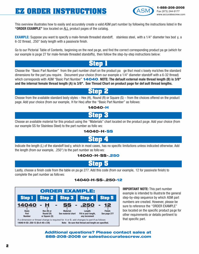
IMPORTANT NOTE: This part numberexample is intended to illustra te the generalstep-by-step sequence by which ASM partnumbers are created. However, please besure to reference the “ORDER EXAMPLE”box located on the specific product pa ge forother requirements or details pertinent tothat specific part.
ORDER EXAMPLE:
If a dimension or thread change is required for A or B, add changes to part # as follows: 14040-H-SS-.250-12 (B=4-40 x 3/8) Note: Be sure that thread and length are specified.
14040BasicPart
Number
HHex (H) orRound (R)
or Square (S)
SSMaterial:
See material chart
.250Length:
Fill in your length,any increment
12Finish:
See page 277
- - - -
This overview illustrates how to easily and accurately create a valid ASM part number by following the instructions listed in the“ORDER EXAMPLE” box located on ALL product pages of the catalog.
EXAMPLE: Suppose you want to specify a male-female threaded standoff, stainless steel, with a 1/4" diameter hex bod y, a 6-32 thread, .250" body length with a passiva te finish.
Go to our Pictorial Table of Contents, beginning on the next pa ge, and find the correct corresponding product pa ge (which forour example is page 27 for male-female threaded standoffs), then follow the step-by-step instructions below:
Step 1Choose the “Basic Part Number” from the part number chart on the product pa ge tha t most c losely matches the standarddimensions for the part you require. Document your choice (from our example a 1/4" diameter standoff with a 6-32 thread)which corresponds with ASM “Basic Part Number” 14040. NOTE: The default external male thread length (B) is 3/8"and the internal female thread length (A) is 3/8". See Thread Chart on product page for def ault thread lengths.
Step 2Choose from the available standard body styles – Hex (H), Round (R) or Square (S) – from the choices offered on the productpage. Add your choice (from our example, H for Hex) after the “Basic Part Number” as follows:
14040-H
Step 3Choose an available material for this product using the “Materials” chart located on the product page. Add your choice (fromour example SS for Stainless Steel) to the part number as follo ws:
14040-H-SS
Step 4Indicate the length (L) of the standoff bod y, which in most cases, has no specific limitations unless indicated otherwise. Addthe length (from our example, .250") to the part number as follo ws:
14040-H-SS-.250
Step 5Lastly, choose a finish code from the table on pa ge 277. Add this code (from our example, 12 for passivate finish) tocomplete the part number as follo ws:
14040-H-SS-.250-12
Additional questions? Please contact sales at888-208-2008 or [email protected]
Step 1 Step 2 Step 3 Step 4 Step 5
3
1-888-208-2008Fax (973) 244-9177
www.accuratescrew.com PICTORIAL TABLE OF CONTENTS
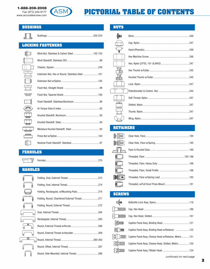
Bushings ......................................................................250-254
Blind Nut, Stainless & Carbon Steel ..............................102-103
Blind Standoff, Stainless 303 .................................................98
Chassis, Square ...................................................................259
Extension Nut, Hex or Round, Stainless Steel .......................101
Extension Nut w/Spline ........................................................105
Flush Nut, Straight Shank .....................................................99
Flush Nut, Tapered Shank ....................................................100
Flush Standoff, Stainless/Aluminum .......................................96
Hi-Torque Data & Index ..........................................................92
Knurled Standoff, Aluminum...................................................95
Knurled Standoff, Steel...........................................................94
Miniature Knurled Standoff, Steel ...........................................93
Press Nut w/Spline...............................................................104
Reverse Flush Standoff, Stainless ..........................................97
Ferrules................................................................................270
Folding, Oval, External Thread ..............................................273
Folding, Oval, Internal Thread ...............................................274
Folding, Rectangular, w/Mounting Plate................................274
Folding, Round, Chamfered External Thread .........................271
Folding, Round, External Thread ...........................................272
Oval, Internal Thread ............................................................264
Rectangular, Internal Thread.................................................265
Round, External Thread w/ferrule .........................................268
Round, External Thread w/shoulder ......................................269
Round, Internal Thread..................................................260-263
Round, Offset, Internal Thread..............................................267
Round, Side-Mounted, Internal Thread .................................266
Blind ....................................................................................248
Cap, Nylon ...........................................................................247
Hand (Phenolic) ....................................................................249
Hex Machine Screw .............................................................246
Hex, Nylon (ZYTEL 101 UL94V2) ...........................................247
Hex Thumb w/Collar.............................................................245
Knurled Thumb w/Collar.......................................................245
Lock, Nylon ..........................................................................247
Potentiometer & Control, Hex ...............................................244
Self-Thread, Nylon ...............................................................247
Slotted, Nylon.......................................................................247
Thumb, Nylon.......................................................................247
Wing, Nylon..........................................................................247
Clear Hole, Flare...................................................................194
Clear Hole, Flare w/Spring....................................................195
Flare & Knurled Data............................................................190
Threaded, Flare ............................................................192-196
Threaded, Flare, Heavy Duty ................................................196
Threaded, Flare, Small Profile ..............................................196
Threaded, Flare w/Spring Load ............................................193
Threaded, w/Full Knurl Press Mount .....................................191
Belleville Lock Assy, Specs...................................................116
Cap, Hex Head .....................................................................186
Cap, Hex Head, Slotted.........................................................187
Captive Panel Assy, Binding Head.........................................121
Captive Panel Assy, Binding Head w/Retainer, .....................122
Captive Panel Assy, Cheese Head w/Retainer, Metric............151
Captive Panel Assy, Cheese Head, Slotted, Metric.................150
Captive Panel Assy, Fillister Head .........................................124
SCREWS
RETAINERS
HANDLES
FERRULES
LOCKING FASTENERS
continued on next page
NUTSBUSHINGS

4
1-888-208-2008Fax (973) 244-9177www.accuratescrew.comPICTORIAL TABLE OF CONTENTS
Captive Panel Assy, Fillister Head w/Retainer ......................125
Captive Panel Assy, Flat Head w/Retainer ............................138
Captive Panel Assy, Hex Head w/Retainer ............................134
Captive Panel Assy, Hex Head w/Retainer, Metric .................155
Captive Panel Assy, Hex Socket Button Head ........................141
Captive Panel Assy, Hex Socket Button Head w/Retainer .....142
Captive Panel Assy, Hex Socket Cap.....................................130
Captive Panel Assy, Hex Socket Cap, Low ............................139
Captive Panel Assy, Hex Socket Cap, Metric .........................152
Captive Panel Assy, Hex Socket, Low w/Retainer .................140
Captive Panel Assy, Machine Screw, Hex Head.....................133
Captive Panel Assy, Machine Screw, Hex Head, Metric .........155
Captive Panel Assy, Pan Head ..............................................118
Captive Panel Assy, Pan Head w/Retainer ............................117
Captive Panel Assy, Pan Head, Metric...................................148
Captive Panel Assy, Pan Head, Metric w/Retainer ................149
Captive Panel Assy, Round Head ..........................................127
Captive Panel Assy, Round Head w/Retainer ........................128
Captive Panel Assy, Security Pan Head .................................145
Captive Panel Assy, Socket Head Cap w/Retainer ................131
Captive Panel Assy, Socket Head Cap, Metric w/Retainer ....153
Captive Panel Assy, Torx Button Head w/Retainer ................144
Captive Panel Assy, Torx Socket Button Head .......................143
Captive, Binding Head ..........................................................120
Captive, Cheese Head, Slotted, Metric ..................................150
Captive, Countersink, Rounded.............................................115
Captive, Fillister Head...........................................................123
Captive, Flat Head Cross-Recessed, Metric ..........................156
Captive, Flat Head Machine, Slotted & Phillips ..............135-136
Captive, Flat Head Slotted Machine, Metric ..........................156
Captive, Flat Head, Hex Socket.............................................137
Captive, Hex Socket Button Head .........................................141
Captive, Hex Socket Cap, Low..............................................139
Captive, Hex Washer Head ...................................................137
Captive, Knurled Head ..................................................113-114
Captive, Machine, Hex Head.................................................132
Captive, Machine, Hex Head, Metric .....................................154
Captive, Oval Countersunk Head ..........................................115
Captive, Pan Head ................................................................117
Captive, Pan Head, Metric ....................................................148
Captive, Round Head............................................................126
Captive, Security Flat Head ..................................................146
Captive, Security Pan Head ..................................................145
Captive, Security Socket Pin Head, Button............................146
Captive, Security Socket Pin Head, Flat ................................146
Captive, Short Knurled Head.................................................113
Captive, Socket Head Cap ....................................................129
Captive, Socket Head Cap, Metric ........................................152
Captive, Thumb Screw w/Knobs ...........................................171
Captive, Torx Socket Button Head .........................................143
FMR2002 Front-Mount Retainer Assembly....................110-112
Hex Socket Cap ...................................................................178
Jack Screw, Hex ....................................................................41
Knurled Phenolic Hand Screws & Nuts .................................249
Machine, Flat Countersunk, Slotted ......................................184
Machine, Hex Head ..............................................................179
Machine, Hex Head, Slotted .................................................182
Machine, Oval Countersunk, Slotted .....................................185
Machine, Pan Head, Slotted..................................................183
Machine, Round Head, Slotted .............................................177
Shoulder, Male/Female.........................................................164
Shoulder, Slotted ..........................................................158-161
continued on next page
SCREWS (continued)SCREWS (continued)
5
1-888-208-2008Fax (973) 244-9177
www.accuratescrew.com PICTORIAL TABLE OF CONTENTS
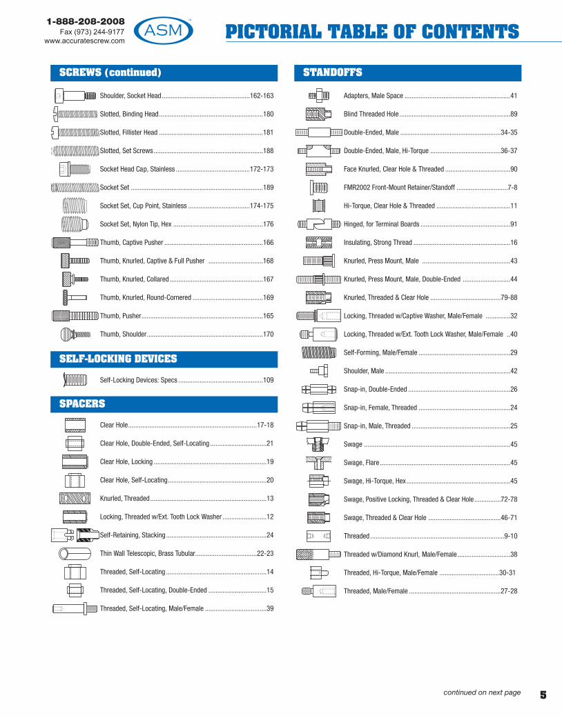
Shoulder, Socket Head..................................................162-163
Slotted, Binding Head...........................................................180
Slotted, Fillister Head ...........................................................181
Slotted, Set Screws..............................................................188
Socket Head Cap, Stainless ..........................................172-173
Socket Set ...........................................................................189
Socket Set, Cup Point, Stainless ...................................174-175
Socket Set, Nylon Tip, Hex ...................................................176
Thumb, Captive Pusher ........................................................166
Thumb, Knurled, Captive & Full Pusher ...............................168
Thumb, Knurled, Collared .....................................................167
Thumb, Knurled, Round-Cornered ........................................169
Thumb, Pusher.....................................................................165
Thumb, Shoulder..................................................................170
Self-Locking Devices: Specs ................................................109
Clear Hole.........................................................................17-18
Clear Hole, Double-Ended, Self-Locating ................................21
Clear Hole, Locking ................................................................19
Clear Hole, Self-Locating........................................................20
Knurled, Threaded..................................................................13
Locking, Threaded w/Ext. Tooth Lock Washer .........................12
Self-Retaining, Stacking.........................................................24
Thin Wall Telescopic, Brass Tubular...................................22-23
Threaded, Self-Locating .........................................................14
Threaded, Self-Locating, Double-Ended .................................15
Threaded, Self-Locating, Male/Female ...................................39
Adapters, Male Space ............................................................41
Blind Threaded Hole ...............................................................89
Double-Ended, Male .........................................................34-35
Double-Ended, Male, Hi-Torque ........................................36-37
Face Knurled, Clear Hole & Threaded .....................................90
FMR2002 Front-Mount Retainer/Standoff .............................7-8
Hi-Torque, Clear Hole & Threaded ..........................................11
Hinged, for Terminal Boards ...................................................91
Insulating, Strong Thread .......................................................16
Knurled, Press Mount, Male ..................................................43
Knurled, Press Mount, Male, Double-Ended ...........................44
Knurled, Threaded & Clear Hole ........................................79-88
Locking, Threaded w/Captive Washer, Male/Female ..............32
Locking, Threaded w/Ext. Tooth Lock Washer, Male/Female ..40
Self-Forming, Male/Female ....................................................29
Shoulder, Male .......................................................................42
Snap-in, Double-Ended ..........................................................26
Snap-in, Female, Threaded ....................................................24
Snap-in, Male, Threaded ........................................................25
Swage ...................................................................................45
Swage, Flare ..........................................................................45
Swage, Hi-Torque, Hex...........................................................45
Swage, Positive Locking, Threaded & Clear Hole...............72-78
Swage, Threaded & Clear Hole .........................................46-71
Threaded ............................................................................9-10
Threaded w/Diamond Knurl, Male/Female..............................38
Threaded, Hi-Torque, Male/Female ..................................30-31
Threaded, Male/Female ....................................................27-28
SPACERS
SELF-LOCKING DEVICES
STANDOFFSSCREWS (continued)
continued on next page
6
1-888-208-2008Fax (973) 244-9177www.accuratescrew.comPICTORIAL TABLE OF CONTENTS
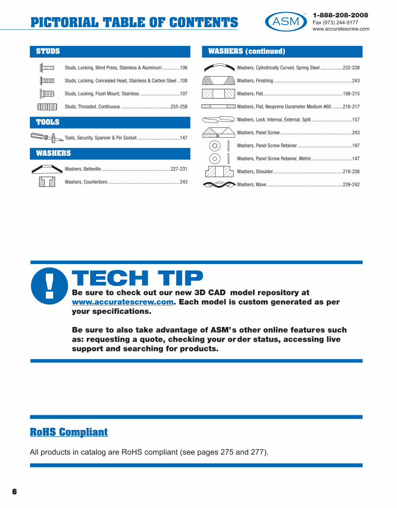
Studs, Locking, Blind Press, Stainless & Aluminum ..............106
Studs, Locking, Concealed Head, Stainless & Carbon Steel ..108
Studs, Locking, Flush Mount, Stainless ................................107
Studs, Threaded, Continuous ........................................255-258
Tools, Security, Spanner & Pin Socket ..................................147
Washers, Belleville........................................................227-231
Washers, Counterbore ..........................................................243
Washers, Cylindrically Curved, Spring Steel ..................232-238
Washers, Finishing ...............................................................243
Washers, Flat................................................................198-215
Washers, Flat, Neoprene Durameter Medium #60 .........216-217
Washers, Lock: Internal, External, Split .................................157
Washers, Panel Screw..........................................................243
Washers, Panel Screw Retainer ............................................197
Washers, Panel Screw Retainer, Metric ................................147
Washers, Shoulder........................................................218-226
Washers, Wave .............................................................239-242
WASHERS
TOOLS
WASHERS (continued)STUDS
RoHS Compliant
All products in catalog are RoHS compliant (see pages 275 and 277).
! TECH TIPBe sure to check out our new 3D CAD model repository atwww.accuratescrew.com. Each model is custom generated as peryour specifications.
Be sure to also take advantage of ASM’s other online features suchas: requesting a quote, checking your order status, accessing livesupport and searching for products.

ST
AN
DO
FFS
&S
PAC
ER
S
1-888-208-2008Fax (973) 244-9177
www.accuratescrew.com STANDOFFS & SPACERS
WHAT IS THE FMR2002?
• The FMR2002 is a pa tented multi-purpose fastenerdeveloped by ASM that is availableexternally/internally threaded for use as a retainerassembly (Fig. A) or threaded standoff (Fig. C) - plusit can be ordered without internal threads for use asa clear-hole standoff/spacer (Fig. B).
• The FMR2002 is completely installed from thefront of a panel due to its unique external threadeddesign – you simply drill, tap, and install with astandard socket or open ended wrench.
• The FMR2002 is produced hex-headed and isavailable in brass, steel, or stainless steel.
HOW DOES THE FMR2002SAVE TIME AND MONEY?
• Reduces Panel Assembly Time up to 20% due tothe unique completely front mount (or single-sided)installation process.
• Cuts Production Setup Costs because there is noneed for anvil/punch sets or equipment, such as anarbor press, punch press, or drill press.
• Eliminates Product Rejection Rates on bent,cracked, or bulging panels because, unlike traditionalswaged or flared products tha t require a pressingforce for installation, the FMR2002 simply screwstightly into place.
• Allows Onsite Product Repair due to its externalthreaded design and installation, which enables theFMR2002 to be easily removed and reused.
Call our Sales Department today a t 1-888-208-2008 forcomplete details.
Visit our Web site at www.accuratescrew.com to view avideo clip of the FMR2002’s easy front mount installa tion.
(Complete product specifications info. located on the next page)
Front-MountRetainer/Standoff
The LatestInnovation in
FastenerTechnology!
Fig. A
Fig. C
Fig. B
7

ST
AN
DO
FFS &
SPA
CE
RS
1-888-208-2008Fax (973) 244-9177www.accuratescrew.comSTANDOFFS & SPACERS
In Applications With Restricted Installation SpaceThe FMR2002 completely installs from the front (or asingle-side) of a panel using a standard socket or openended wrench (Fig. C). This dramatically reduces clearanceand accessibility constraints normally associa ted withtraditional retainer/standoff products that require installationusing a press, anvil, or punch (Fig. D).
In Applications With Panel Edge Distortion ConcernsThe FMR2002 can be installed much c loser to the edge of apanel (Fig. E) than a traditional retainer/standoff withoutconcerns about panel distortion. This is possible becausethe shank portion of the FMR2002 is screwed in ra ther thanpressed, which lessens the force and stress a pplied to thepanel material, eliminating any bulging or cracking issues(Fig. F).
THE FMR2002 IS A PERFECT CHOICEFOR USE IN PCB APPLICATIONS!See Fig. G
Installed
76256 2-56 .125 .062 8-32 3/1676440 4-40 .125 .093 10-32 1/476632 6-32 .125 .093 1/4-28 5/1676832 8-32 .125 .093 1/4-28 5/16761032 10-32 .125 .093 5/16-24 3/8761024 10-24 .125 .093 5/16-24 3/8762520 1/4-20 .125 .125 3/8-24 7/16
BasicPart
Number
CaptiveScrew
Thread Size
RMin
P M SHex
A AluminumB Brass, composition 360
S Steel, low carbon 1018 ASTM 108
SS Stainless Steel18-8, 302-304 series, ASTMA 580/A580M-98
Available Material(see page 275)
Front-Mount Retainer/Standoff
PC Board
The FMR2002 is an excellent alternative to existing flared and swage standoff products…
ORDER EXAMPLE:
Any dimension may be changed by adding to part number .EXAMPLE: 76256 H SS 12 (R = .187)
76256Basic
Part Number
HHex Only
SSMaterial:See chart
12Finish:
See page 277
- - -
Fig. C Fig. D
Fig. GFig.E
ScrewThread
ID CodeLetter
ScrewThread
ID CodeLetter
To specify Clear Hole Option, add prefix code to part number.EXAMPLE: A76256-H-SS-12
.100 - ID
Available ID and Appropriate Code
#2 .100 A #8 .180 D#4 .128 B #10 .213 E#6 .156 C #1/4 .281 F
+.010–.000
+.010–.000
CLEAR HOLESTANDOFFS
For FMR2002 captive screw assembly information please refer to the product section starting on pa ge 110.
Fig.F
8

ST
AN
DO
FFS
&S
PAC
ER
S
9
1-888-208-2008Fax (973) 244-9177
www.accuratescrew.com STANDOFFS & SPACERS
THREADED STANDOFFS
NOTE: Hi-Torque Feature (see page 11), Locking Standoff (see page 12), Insulating Standof f (see page 16).
1/8 0-80 90102-56 1016
5/32 4-40 10172-56 1020
3/16 4-40 10306-32 10312-56 11104-40 1120
1/4 6-32 11308-32 1140
10-32 11502-56 12104-40 12206-32 1230
5/16 8-32 124010-32 12501/4-20 1253
2-56 13104-40 13206-32 13308-32 1340
3/8 10-24 134510-32 13501/4-20 13521/4-28 1353
2-56 14104-40 14206-32 1430
7/16 8-32 144010-24 145010-32 14601/4-20 1470
A Aluminum Ph** Phenolic (Paper)B Brass Phl** Phenolic (Linen)C Copper L** Polycarbonate (Lexan)S Steel PA** A.B.S
SS Stainless Steel PP** P.V.CN Nylon T TeflonD Delrin F** Fiber
UL* ULTEM 1000 KF** Kel-F*ULTEM 1000 UL Rating 94V-0 **Supplied in round only .
Available Material (see page 275)
Thread
(see page 109)
OD Thread Basic Part No. H or R or S Material Length Finish
ORDER EXAMPLE:
If a different thread on each end is needed, including Metric, add to end of part number . EXAMPLE: 1130-H- SS-.500-12 (one end 4-40 thd.)
9010BasicPart
Number
RHex (H) orRound (R)
or Square (S)
SSMaterial:See chart
.250Length:
Fill in your length,any increment
12Finish:
See page 277
- - - -
*Thread sizes available for 7/16 OD and larger .For Dep h of Thread information, see page 281.
0-802-564-406-328-32
10-2410-321/4-201/4-283/8-16*
3/8-24*5/16-18*7/16-14*

ST
AN
DO
FFS &
SPA
CE
RS
10
1-888-208-2008Fax (973) 244-9177www.accuratescrew.comSTANDOFFS & SPACERS
THREADED STANDOFFS
NOTE: Hi-Torque Feature (see page 11), Locking Standoff (see page 12), Insulating Standof f (see page 16).
2-56 15104-40 15206-32 15308-32 1540
1/2 10-24 155010-32 156012-24 15701/4-20 15801/4-28 1581
4-40 16106-32 16208-32 1630
10-24 164010-32 1650
5/8 3/8-24 165112-24 16601/4-20 1670
5/16-18 16803/8-16 1682
7/16-14 16852-56 21004-40 21056-32 21108-32 2115
10-24 212010-32 21253/4 12-24 21301/4-20 21351/4-28 2140
5/16-18 21453/8-16 2150
7/16-14 2155
A Aluminum Ph** Phenolic (Paper)B Brass Phl** Phenolic (Linen)C Copper L** Polycarbonate (Lexan)S Steel PA** A.B.S
SS Stainless Steel PP** P.V.CN Nylon T TeflonD Delrin F** Fiber
UL* ULTEM 1000 KF** Kel-F*ULTEM 1000 UL Rating 94V-0 **Supplied in round only .
Available Material (see page 275)
(see page 109)
OD Thread Basic Part No. H or R or S Material Length Finish
ORDER EXAMPLE:
If a different thread on each end is needed, including Metric, add to end of part number . EXAMPLE: 1550-H- SS-.500-12 (one end 10-32 thd.)
1510BasicPart
Number
RHex (H) orRound (R)
or Square (S)
SSMaterial:See chart
.250Length:
Fill in your length,any increment
12Finish:
See page 277
- - - -
For Depth of Thread informa ion, see page 281.
Thread
2-564-406-328-32
10-24
10-3212-241/4-201/4-283/8-16
3/8-245/16-187/16-14

ST
AN
DO
FFS
&S
PAC
ER
S
11
1-888-208-2008Fax (973) 244-9177
www.accuratescrew.com STANDOFFS & SPACERS
CONVENTIONAL SPACERS SPIN EASILYConventional No-Grip
HI-TORQUE SPACER OFFERS MAXIMUM TORQUESix Point Grip
HI-TORQUE THREADED & CLEAR HOLE SPACERSHex or Square
LOCKS SPACERS, SAMPLES AVAILABLE
1. Refer to Clear Hole and Threaded Spacers on pages 9-21.2. Add letter designation (HT) to part number according to the order example below .
ORDER EXAMPLE:
If Hi-Torque factor is required on one side, indicate: EXAMPLE: 1130-H-A-.500-1 (HT one side only)
1130BasicPart
Number
HHex (H) orSquare (S)
AMaterial:See chart
.500OverallLength: L ± .005
1Finish:
See page 277
HTHi-Torque
- - - - -
L
HI-TORQUE SWAGE STANDOFF
A STANDOFF THAT WON’T SPIN!Hi-Torque hex swage standoff with a locking feature that ends loosening & spinning problems
*This feature is also available for Male/FemaleStandoffs see pages 27-28.
HI-TORQUE HEX SWAGEGRIPPING STANDOFF*
Up to 23 in/lb - 6 Flats Really Grip!Six flats really grip the board to provide the highesttorque installation achievable yet.
HEX SWAGENO-GRIP STANDOFF
Conventional No-Grip!
Noadditionaltoolingrequired.

Min Max Min Max Min Max
ST
AN
DO
FFS &
SPA
CE
RS
12
1-888-208-2008Fax (973) 244-9177www.accuratescrew.comSTANDOFFS & SPACERS
LOCKING THREADED SPACERSAvailable in Hex, Round or Square
Thread
Washer Size
NOTE: For depth of hread, see page 281.
Lock WasherMaterial Finish
S Steel - 1040/1060 Zinc Chrome ClearSS Stainless Steel - 410 NONE
ORDER EXAMPLE:
No specific increments required for length.To order Lock Washer in steel (1040/1060) add LS to end of part number: EXAMPLE: 1020-R-S-.250-LS -12To order Lock Washer on bo h ends add LL to end of part number: EXAMPLE: 1020-R-SS-.250-LLSS-12
1020BasicPart
Number
RHex (H),
Round (R)or Square (S)
SSSpacer
Material:See chart
.250Length L:
Fill in your length,any increment
LSSLock Washer
Material:Stainless (LSS)
or Steel (LS)
12Finish:
See page 277
- - - - -
A AluminumB Brass
C CopperS Steel
SS Stainless Steel
Threaded Spacer Available Material(see page 275)
AInside
Diameter
B Outside
Diameter
CThickness
2-56 .115 .123 .245 .260 .015 .0194-40 .141 .150 .305 .320 .016 .0226-32 .168 .176 .365 .381 .018 .0298-32 .195 .204 .395 .410 .020 .025
10-32 .258 .267 .494 .510 .023 .028
OD ThreadBasic Washer
Part Number Number
2-56 10203/16 4-40 10302-56 11101/4 4-40 11202-56 12104-40 1220
5/16 6-32 12308-32 1240
10-32 12502-56 13104-40 13206-32 13303/8 8-32 1340
10-24 134510-32 1350
OD ThreadBasic
Part Number
2-56 1410 44-40 1420 66-32 1430 87/16 8-32 1440 10
10-24 1450 1/410-32 1460 1/42-56 1510 44-40 1520 66-32 1530 81/2 8-32 1540 10
10-24 1550 1/410-32 1560 1/44-40 1610 66-32 1620 8
5/8 8-32 1630 1010-24 1640 1/410-32 1650 1/42-56 2100 44-40 2105 66-32 2110 8
3/4 8-32 2115 1010-24 2120 1/410-32 2125 1/412-24 2130 1/4
! TECHTIPMetric sizes and threads are available on many of the productswe manufacture.

ST
AN
DO
FFS
&S
PAC
ER
S
13
1-888-208-2008Fax (973) 244-9177
www.accuratescrew.com STANDOFFS & SPACERS
NOTE: When length is 2" or longer, 3/4" will be knurled from each end. For depth of thread, see page 281.
L
KNURLED THREADED SPACERS
A AluminumB BrassS Steel
SS Stainless Steel
Available Material (see page 275)
ThreadBasic
Part NumberA
Dia
5/32 2-56 19002-64 19053-48 19103-56 19153/16 4-40 19204-48 1925
7/32 6-32 19306-40 19354-40 1941
1/4 6-32 19428-32 19438-32 1944
9/32 10-24 195010-32 19558-32 1957
3/8 1/4-20 19601/4-28 1965
7/16 5/16-18 19705/16-24 1975
1/2 3/8-16 19803/8-24 1985
Length FinishMaterial
ORDER EXAMPLE:1900
BasicPart
Number
AMaterial:See chart
.125Length:
Fill in your length,any increment
22Finish:
See page 277
- - -
Thread
2-562-643-483-564-40
6-328-32
10-2410-321/4-20
1/4-285/16-185/16-243/8-163/8-24
APPLICATION:These inserts can be die cast into aluminum and zinc, used in plastic andmetal sheets, injection and compression molded.
ST
AN
DO
FFS &
SPA
CE
RS
14
1-888-208-2008Fax (973) 244-9177www.accuratescrew.comSTANDOFFS & SPACERS
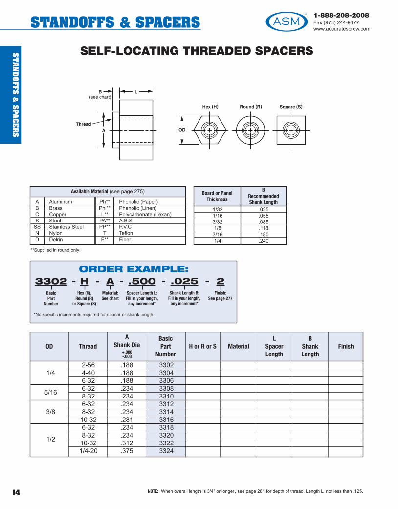
SELF-LOCATING THREADED SPACERS
NOTE: When overall length is 3/4" or longer , see page 281 for depth of thread. Length L not less than .125.
Board or Panel Thickness
BRecommendedShank Length
1/32 .0251/16 .0553/32 .0851/8 .1183/16 .1801/4 .240
OD ThreadA
Shank Dia+.000-.003
BasicPart
Number
2-56 .188 33021/4 4-40 .188 3304
6-32 .188 33066-32 .234 33085/16 8-32 .234 33106-32 .234 3312
3/8 8-32 .234 331410-32 .281 33166-32 .234 33188-32 .234 332010-32 .312 33221/2
1/4-20 .375 3324
B L
MaterialL
SpacerLength
BShank Length
Finish
A Aluminum Ph** Phenolic (Paper)B Brass Phl** Phenolic (Linen)C Copper L** Polycarbonate (Lexan)S Steel PA** A.B.S
SS Stainless Steel PP** P.V.CN Nylon T TeflonD Delrin F** Fiber
**Supplied in round only.
Available Material (see page 275)
H or R or S
ORDER EXAMPLE:
*No specific increments required for spacer or shank length.
- - - - -3302BasicPart
Number
HHex (H),
Round (R)or Square (S)
AMaterial:See chart
.500Spacer Length L:Fill in your length,
any increment*
.025Shank Length B:
Fill in your length,any increment*
2Finish:
See page 277

ST
AN
DO
FFS
&S
PAC
ER
S
15
1-888-208-2008Fax (973) 244-9177
www.accuratescrew.com STANDOFFS & SPACERS
Board orPanel
Thickness
C and DRecommendedShank Length
1/32 .0251/16 .0553/32 .0851/8 .1183/16 .1801/4 .240
A Aluminum Ph** Phenolic (Paper)B Brass Phl** Phenolic (Linen)C Copper L** Polycarbonate (Lexan)S Steel PA** A.B.S
SS Stainless Steel PP** P.V.CN Nylon T TeflonD Delrin F** Fiber
**Supplied in round only.
Available Material (see page 275)
SELF-LOCATING, DOUBLE-ENDEDTHREADED SPACERS
H or R or S
310231043106310831103112311431163118312031223124
OD ThreadA & B
Shank Dia +.000-.003
BasicPart
Number
2-56 .1881/4 4-40 .188
6-32 .1886-32 .2345/16 8-32 .2346-32 .234
3/8 8-32 .23410-32 .2816-32 .2348-32 .23410-32 .3121/2
1/4-20 .375
MaterialL
SpacerLength
C & DShank Length
Finish
NOTE: When overall length is 3/4" or longer , see page 281 for depth of thread. Length L not less han .125.
ORDER EXAMPLE:
*No specific increments required for spacer or shank length.
- - - - -3102BasicPart
Number
HHex (H),
Round (R)or Square (S)
AMaterial:See chart
.500Spacer Length L:Fill in your length,
any increment*
.025Shank Length C & D:
Fill in your length,any increment*
2Finish:
See page 277
! TECHTIPTorque-tension formulaand tables are usefulin determining therequired torque.However, the only sure way to establishthe “correct” torque is throughexperimentationutilizing the actualfasteners or one thatclosely simulates it.

InternalThread Size
(Inches)
InternalThread Size
(Metric)
DDiameter
LInsert Length
RecommendedHole Size
2-56 M2 x 0.4 .141 .187 .127-.1244-40 M3 x 0.5 .171 .234 .152-.1496-32 M3.5 x 0.6 .218 .281 .194-.1908-32 M4 x 0.7 .250 .328 .226-.2228-32 M4 x 0.7 .250 .218 .226-.222
10-32 M5 x 0.8 .296 .375 .264-.2591/4-20 M6 x 1 .375 .312 .330-.336
ST
AN
DO
FFS &
SPA
CE
RS
16
1-888-208-2008Fax (973) 244-9177www.accuratescrew.comSTANDOFFS & SPACERS
STRONG INSULATING THREADED STANDOFFS*
SELF-THREADING INSERT FOR THERMOPLASTICS AND THERMOSET PLASTICS
Brass inserts are designed for maximum pullout strength, superior vibration resistance. D is a special thread designed for ease of installation and strength.
D DelrinN NylonT Teflon
L** Polycarbonate (Lexan)PA** A.B.S..PP** P.V.C..UL* ULTEM 1000
Available Material (see page 275)
MALE/FEMALE STANDOFFSOTHER OPTIONS:
Insert Mounting Hole
1" minimum length required.
*See pages starting on 275 for further specifications, tolerance, etc.
*ULTEM 1000 - UL Rating 94V-0**Supplied in round only.
ORDER EXAMPLE:
For Threaded Standoff Basic Part Number, see pages 9, 10, 14 or 15.Add letters LI (Locking Insert) to part number as shown above to specify strong insulating feature. EXAMPLE: 1130-H-N-.625-LI-1METRIC THREADED EXAMPLE: 1130-H-N-.625-LI-1-(M3.5x0.6)
1130BasicPart
Number
HHex (H),
Round (R)or Square (S)
NMaterial:See chart
.625Fill in yourlength, anyincrement
LILockingInsert
1Finish:
See page277
(M3.5x0.6)Metric
Requirement
- - - - - -
ORDER EXAMPLE:
For Threaded Standoff Basic Part Number, see pages 9, 10, 14 or 15.Add letters LI (Locking Insert) to part number as shown above to specifystrong insulating feature. EXAMPLE: 14040-H-N-.500-LI-1
14040BasicPart
Number
HHex (H),
Round (R)or Square (S)
NMaterial:See chart
.500Fill in yourlength, anyincrement
LILockingInsert
1Finish:
See page277
- - - - -
ST
AN
DO
FFS
&S
PAC
ER
S
17
1-888-208-2008Fax (973) 244-9177
www.accuratescrew.com STANDOFFS & SPACERS
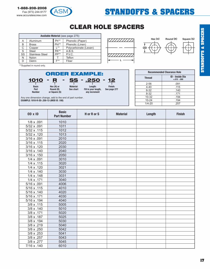
CLEAR HOLE SPACERS
Thread ID - Inside Dia +.015 -.000
2-56 .0914-40 .1156-32 .1408-32 .17110-32 .19410-24 .1941/4-20 .257
1/8 x .091 10105/32 x .091 10115/32 x .115 10125/32 x .120 10133/16 x .091 20103/16 x .115 20203/16 x .120 20303/16 x .140 20403/16 x .150 20501/4 x .091 30101/4 x .115 30201/4 x .120 30211/4 x .140 30301/4 x .148 30311/4 x .171 3040
5/16 x .091 40065/16 x .115 40105/16 x .140 40205/16 x .171 40305/16 x .194 40403/8 x .115 50053/8 x .140 50103/8 x .171 50203/8 x .187 50253/8 x .194 50303/8 x .219 50403/8 x .250 50423/8 x .253 50413/8 x .257 50433/8 x .277 5045
7/16 x .140 6010
A Aluminum Ph** Phenolic (Paper)B Brass Phl** Phenolic (Linen)C Copper L** Polycarbonate (Lexan)S Steel PA** A.B.S.
SS Stainless Steel PP** P.V.C.N Nylon T TeflonD Delrin F** Fiber
**Supplied in round only.
Available Material (see page 275)
Recommended Clearance Hole
OD x IDBasic
Part NumberH or R or S Material Length Finish
ORDER EXAMPLE:
Any one dimension change, add to the end of part number . EXAMPLE: 1010-R-SS-.250-12-(MOD ID .100)
1010BasicPart
Number
RHex (H) orRound (R)
or Square (S)
SSMaterial:See chart
.250Length:
Fill in your length,any increment
12Finish:
See page 277
- - - -

ST
AN
DO
FFS &
SPA
CE
RS
18
1-888-208-2008Fax (973) 244-9177www.accuratescrew.comSTANDOFFS & SPACERS
CLEAR HOLE SPACERS
7/16 x .171 60207/16 x .194 60301/2 x .140 70101/2 x .171 70201/2 x .194 70301/2 x .219 70401/2 x .257 70505/8 x .140 80105/8 x .171 80205/8 x .194 80305/8 x .219 80405/8 x .257 80505/8 x .281 80605/8 x .312 80705/8 x .315 80715/8 x .375 80805/8 x .406 80905/8 x .437 80953/4 x .140 88003/4 x .171 88053/4 x .194 88103/4 x .219 88153/4 x .257 88203/4 x .281 88253/4 x .312 88303/4 x .375 80973/4 x .380 88313/4 x .406 88353/4 x .437 88403/4 x .440 88413/4 x .505 8845
A Aluminum Ph** Phenolic (Paper)B Brass Phl** Phenolic (Linen)C Copper L** Polycarbonate (Lexan)S Steel PA** A.B.S.
SS Stainless Steel PP** P.V.C.N Nylon T TeflonD Delrin F** F ber
**Supplied in round only.
Available Material (see page 275)
OD x IDBasic
Part NumberH or R or S Material Length Finish
ORDER EXAMPLE:
Any one dimension change, add to the end of part number . EXAMPLE: 6020-R-SS-.250-12-(MOD ID .100)
6020BasicPart
Number
RHex (H) orRound (R)
or Square (S)
SSMaterial:See chart
.250Length:
Fill in your length,any increment
12Finish:
See page 277
- - - - Thread ID - Inside Dia +.015 -.000
2-56 .0914-40 .1156-32 .1408-32 .171
10-32 .19410-24 .1941/4-20 .257
Recommended Clearance Hole
Thread ID - Inside Dia +.015 -.000
1/4-28 .2575/16-18 .3153/8-24 .3803/8-16 .380
7/16-14 .4401/2-13 .505

ST
AN
DO
FFS
&S
PAC
ER
S
19
1-888-208-2008Fax (973) 244-9177
www.accuratescrew.com STANDOFFS & SPACERS
LOCKING CLEAR HOLE SPACERSAVAILABLE IN HEX, ROUND OR SQUARE
OD x ID BasicPart Number
WasherNumber
7/16 x .1407/16 x .1717/16 x .1941/2 x .1401/2 x .1711/2 x .1945/8 x .1405/8 x .1715/8 x .1943/4 x .1403/4 x .1713/4 x .194
601060206030701070207030801080208030880088058810
81012810128101281012
3/16 x .0913/16 x .1201/4 x .0911/4 x .1151/4 x .120
5/16 x .0915/16 x .1155/16 x .1405/16 x .1715/16 x .1943/8 x .1153/8 x .1403/8 x .1713/8 x .1873/8 x .194
201020303010302030214006401040204030404050055010502050255030
46466468101268101212
RecommendedClearance Hole
2-564-406-328-3210-2410-32
.091
.115
.140
.171
.194
.194
Thread
Washer SizeA
InsideDiameter
B Outside
Diameter
CThickness
Lock WasherMaterial Finish
S Steel - 1040/1060SS Stainless Steel - 410
Zinc Chrome ClearNONE
A Aluminum
B Brass
C Copper
S Steel
SS Stainless Steel
Clear Hole Spacer Available Material
(see page 275)
NOTE: For depth of thread, see page 281.
OD x IDBasic
Part NumberWasherNumber
ThreadID - Inside Dia
+.010-.000
ORDER EXAMPLE:
No specific increments required for length.NOTE: To order Lock Washer on both ends, just add LL to end of part number. EXAMPLE: 2010-R-SS-.250-LLSS-12
2010BasicPart
Number
RHex (H),
Round (R)or Square (S)
SSSpacer
Material:See chart
.250Length L:
Fill in your length,any increment
LSSLock Washer
Material:Stainless (LSS)
or Steel (LS)
12Finish:
See page 277
- - - - -
Min Max Min Max Min Max2-56 .115 .123 .245 .260 .015 .0194-40 .141 .150 .305 .320 .016 .0226-32 .168 .176 .365 .381 .018 .0298-32 .195 .204 .395 .410 .020 .025
10-24 .258 .267 .494 .510 .023 .02810-32 .258 .267 .494 .510 .023 .028

ST
AN
DO
FFS &
SPA
CE
RS
20
1-888-208-2008Fax (973) 244-9177www.accuratescrew.comSTANDOFFS & SPACERS
SELF-LOCATING CLEAR HOLE SPACERS
Board or Panel
Thickness
BRecommendedShank Length
1/32 .0251/16 .0553/32 .0851/8 .1183/16 .1801/4 .240
1/4 x .091 .188 33401/4 x .120 .188 33421/4 x .140 .188 3344
5/16 x .115 .234 33465/16 x .140 .234 33485/16 x .171 .234 33505/16 x .194 .234 33523/8 x .140 .234 33543/8 x .171 .234 33563/8 x .194 .257 33581/2 x .140 .257 33601/2 x .171 .257 33621/2 x .194 .257 33641/2 x .219 .312 33661/2 x .257 .375 3368
A Aluminum Ph** Phenolic (Paper)B Brass Phl** Phenolic (Linen)C Copper L** Polycarbonate (Lexan)S Steel PA** A.B.S.
SS Stainless Steel PP** P.V.C.N Nylon T TeflonD Delrin F** F ber
**Supplied in round only.
Available Material(see page 275) Natural 1
Black 2Red 3Blue 4Purple 5Brown 6Orange 7Green 8Yellow 9
Color Code
ORDER EXAMPLE:
No specific increments required for length.EXAMPLE FOR NYLON AND DELRIN PARTS: 3340-H-N-.500-.025-2 BLACKChoose color from chart, otherwise Natural is provided.Any one dimension change can be added to the end of part number . EXAMPLE: 3340-H-A-.500-.025-3 (MOD ID = .060)
- - - - -3340BasicPart
Number
HHex (H),
Round (R)or Square (S)
AMaterial:See chart
.500Spacer Length L:Fill in your length,
any increment*
.025Shank Length B:
Fill in your length,any increment*
2Finish:
See page 277
OD x ID+.010-.005
A Shank Dia+.000-.003
Basic Part
Number
Hex or Round orSquare
MaterialL
Spacer Length
BShankLength
Finish
! TECHTIPNylon and Delrinparts are suppliedin nine differentcolors.
ST
AN
DO
FFS
&S
PAC
ER
S
21
1-888-208-2008Fax (973) 244-9177
www.accuratescrew.com STANDOFFS & SPACERS
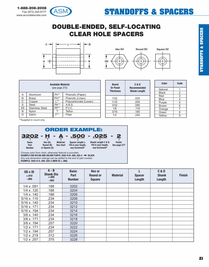
ORDER EXAMPLE:
Choose color from chart, otherwise Natural is provided.EXAMPLE FOR NYLON AND DELRIN PARTS: 3202-H-N-.500-.025-2 BLACKAny one dimension change can be added to the end of part number . EXAMPLE: 3202-H-A-.500-.025-3 (MOD ID = .060)
- - - - -3202BasicPart
Number
HHex (H),
Round (R)or Square (S)
AMaterial:See chart
.500Spacer Length L:Fill in your length,
any increment*
.025Shank Length C & D:
Fill in your length,any increment*
2Finish:
See page 277
DOUBLE-ENDED, SELF-LOCATINGCLEAR HOLE SPACERS
1/4 x .091 .188 32021/4 x .120 .188 32041/4 x .140 .188 3206
5/16 x .115 .234 32085/16 x .140 .234 32105/16 x .171 .234 32125/16 x .194 .234 32143/8 x .140 .234 32163/8 x .171 .234 32183/8 x .194 .257 32201/2 x .171 .234 32221/2 x .194 .257 32241/2 x .219 .312 32261/2 x .257 .375 3228
Board Or Panel
Thickness
C & DRecommendedShank Length
1/32 .0251/16 .0553/32 .0851/8 .1183/16 .1801/4 .240
A Aluminum Ph** Phenolic (Paper)B Brass Phl** Phenolic (Linen)C Copper L** Polycarbonate (Lexan)S Steel PA** A.B.S.
SS Stainless Steel PP** P.V.C.N Nylon T TeflonD Delrin F** Fiber
**Supplied in round only.
Available Material(see page 275) Natural 1
Black 2Red 3Blue 4Purple 5Brown 6Orange 7Green 8Yellow 9
Color Code
OD x ID+.010-.005
A - BShank Dia
+.000-.003
Basic Part
Number
Hex or Round orSquare
MaterialL
Spacer Length
C & DShank
LengthFinish
ST
AN
DO
FFS &
SPA
CE
RS
22
1-888-208-2008Fax (973) 244-9177www.accuratescrew.comSTANDOFFS & SPACERS
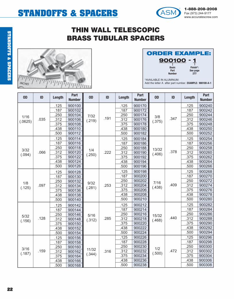
THIN WALL TELESCOPICBRASS TUBULAR SPACERS
1/16(.0625) .035
.125
.187
.250
.312
.375
.438
.500
900100900102900104900106900108900110900112
3/32(.094) .066
.125
.187
.250
.312
.375
.438
.500
900114900116900118900120900122900124900126
1/8(.125) .097
.125
.187
.250
.312
.375
.438
.500
900128900130900132900134900136900138900140
5/32(.156) .128
.125
.187
.250
.312
.375
.438
.500
900142900144900146900148900150900152900154
.159
.125
.187
.250
.312
.375
.438
.500
900156900158900160900162900164900166900168
7/32(.219) .191
.125
.187
.250
.312
.375
.438
.500
900170900172900174900176900178900180900182
1/4(.250) .222
.125
.187
.250
.312
.375
.438
.500
900184900186900188900190900192900194900196
9/32(.281) .253
.125
.187
.250
.312
.375
.438
.500
900198900200900202900204900206900208900210
5/16(.312) .285
.125
.187
.250
.312
.375
.438
.500
900212900214900216900218900220900222900224
11/32(.344)
.316
.125
.187
.250
.312
.375
.438
.500
900226900228900230900232900234900236900238
3/8(.375)
.347
.125
.187
.250
.312
.375
.438
.500
900240900242900244900246900248900250900252
13/32(.406) .378
.125
.187
.250
.312
.375
.438
.500
900254900256900258900260900262900264900266
7/16(.438) .409
.125
.187
.250
.312
.375
.438
.500
900268900270900272900274900276900278900280
15/32(.468) .440
.125
.187
.250
.312
.375
.438
.500
900282900284900286900288900290900292900294
1/2(.500) .472
.125
.187
.250
.312
.375
.438
.500
900296900298900300900302900304900306900308
3/16(.187)
ORDER EXAMPLE:
*AVAILABLE IN ALUMINUM:Add the letter A after part number. EXAMPLE: 900100-A-1
900100BasicPart
Number
1Finish*:
See page277
-
OD ID LengthPart
NumberOD ID Length
PartNumber
OD ID LengthPart
Number

ST
AN
DO
FFS
&S
PAC
ER
S
23
1-888-208-2008Fax (973) 244-9177
www.accuratescrew.com STANDOFFS & SPACERS
THIN WALL TELESCOPICBRASS TUBULAR SPACERS
3/32(.094) .036
.125
.187
.250
.312
.375
.438
.500
900310900312900314900316900318900320900322
1/8(.125) .067
.125
.187
.250
.312
.375
.438
.500
900324900326900328900330900332900334900336
5/32(.156) .098
.125
.187
.250
.312
.375
.438
.500
900338900340900342900344900346900348900350
3/16(.187)
.129
.125
.187
.250
.312
.375
.438
.500
900352900354900356900358900360900362900364
7/32(.219) .161
.125
.187
.250
.312
.375
.438
.500
900366900368900370900372900374900376900378
1/4(.250) .192
.125
.187
.250
.312
.375
.438
.500
900380900382900384900386900388900390900392
9/32(.281) .223
.125
.187
.250
.312
.375
.438
.500
900394900396900398900400900402900404900406
5/16(.312) .254
.125
.187
.250
.312
.375
.438
.500
900408900410900412900414900416900418900420
11/32(.344)
.286
.125
.187
.250
.312
.375
.438
.500
900422900424900426900428900430900432900434
3/8(.375) .317
.125
.187
.250
.312
.375
.438
.500
900436900438900440900442900444900446900448
7/16(.438) .380
.125
.187
.250
.312
.375
.438
.500
900450900452900454900456900458900460900462
1/2(.500) .442
.125
.187
.250
.312
.375
.438
.500
900464900466900468900470900472900474900476
ORDER EXAMPLE:
*AVAILABLE IN ALUMINUM:Add the letter A after part number. EXAMPLE: 900310-A-1
900310BasicPart
Number
1Finish*:
See page277
-
OD ID LengthPart
NumberOD ID Length
PartNumber
OD ID LengthPart
Number

ST
AN
DO
FFS &
SPA
CE
RS
24
1-888-208-2008Fax (973) 244-9177www.accuratescrew.comSTANDOFFS & SPACERS
A Aluminum B BrassC* Copper S SteelPA* A.B.S. SS Stainless SteelPP* P.V.C. N Nylon
T Teflon D DelrinUL* ULTEM 1000
*Supplied in round only.
Available Material (see page 275)
SELF-RETAINING SPACERSSelf-retaining and aligning • 1/16" Board Thickness • Material: Nylon LP410
*#4 screw size in lengths up to 5/8 (15.9) only .**#6 and #8 screw size not available in 1/8 (3.2) or 3/16 (4.8) lengths.
1/16" Board Thickness(To snap fit in a .152 + .002 dia hole)
3/32" Board Thickness(To snap fit in a .152 + .002 dia hole)
Natural 1Black 2Red 3Blue 4Purple 5
Brown 6Orange 7Green 8Yellow 9
Color Code Color Code
FEMALE “SNAP-IN” THREADED STANDOFF
(see page 281) (see page 281)
ORDER EXAMPLE:1130
BasicPart Number
HHex
AMaterial:See chart
.500Length
SNSnap-inBoard
- - - -
Select spacer requirements from pages 9-10.For Snap-in 1/16 board, add SN to part number . EXAMPLE: 1130-H-A-.500-SNFor Snap-in 3/32 board add SNN to part number . EXAMPLE: 1130-H- A-.500-SNNFor Nylon and Delrin parts, choose color from chart, otherwise Natural is provided.EXAMPLE: 1130-H-N-.500-SN-2 BLACK
ORDER EXAMPLE:
*No specific increments required for length.
561BasicPart
Number
1Color:
See chart
-.526Length availablefrom 1/8 to 5/8or fill in yourown length*
-
561 .260 (6.6) .125 (3.1) .203 .182 .064 .050 #4 .187 (4.7)562 9/32 (7.1) .153 (3.9) .250 .228 .064 .050 #6 .234 (5.9)563 9/32 (7.1) .169 (4.3) .250 .228 .064 .050 #8 .234 (5.9)
Basic Part No.
A DimInches (mm)
B DimInches (mm)
C DimInches (mm)
D DimInches (mm)
E DimInches (mm)
SlotWidth
ScrewSize
Mounting Hole +.003 In. (mm)
SELF-RETAINING STACKING SPACERSSelf-retaining and aligning • 1/16" Board Thickness • Material: Nylon LP410
Natural 1Black 2Red 3Blue 4Purple 5
Brown 6Orange 7Green 8Yellow 9
Color Code Color CodeORDER EXAMPLE:
*No specific increments required for length.
564BasicPart
Number
1Color:
See chart
-.526Length availablefrom 1/8 to 1.00
or fill in yourown length*
-
564 1/4 (6.3) .125 (3.1) .203 .182 .064 .050 #4* .187 (4.7)565 5/16 (7.1) .153 (3.9) .250 .228 .064 .050 #6** .234 (5.9)566 5/16 (7.1) .169 (4.3) .250 .228 .064 .050 #8** .234 (5.9)
Basic Part No.
A DimInches (mm)
B DimInches (mm)
C DimInches (mm)
D DimInches (mm)
E DimInches (mm)
SlotWidth
ScrewSize
Mounting Hole +.003 In. (mm)

ST
AN
DO
FFS
&S
PAC
ER
S
25
1-888-208-2008Fax (973) 244-9177
www.accuratescrew.com STANDOFFS & SPACERS
Available Material (see page 275)
MALE “SNAP-IN” THREADED STANDOFF1/16" Board Thickness
Thread B
2-564-406-328-3210-32
3/161/43/87/161/2
A Aluminum B BrassC* Copper S SteelPA* A.B.S. SS Stainless SteelPP* P.V.C. N Nylon
T Teflon D DelrinUL* ULTEM 1000
*Supplied in round only.
3/32" Board Thickness
3/16
1/4
5/16
3/8
2-564-406-322-564-406-328-322-564-406-328-3210-322-564-406-328-32
10-32
1450014502145041450614508145101451214514145161451814520145221452414526145281453014532
Available Material (see page 275)
A Aluminum B BrassC* Copper S SteelPA* A.B.S. SS Stainless SteelPP* P.V.C. N Nylon
T Teflon D DelrinUL* ULTEM 1000
*Supplied in round only.
ORDER EXAMPLE:14500
BasicPart
Number
HHex (H) orRound (R)
SSMaterial:See chart
.250Length:
Fill in your length,any increment
2Finish:
See page277
----
ORDER EXAMPLE:14501
BasicPart
Number
HHex (H) orRound (R)
SSMaterial:See chart
.250Length:
Fill in your length,any increment
12Finish:
See page277
----
Thread B
2-564-406-328-3210-32
3/161/43/87/161/2
(To snap fit in a.152 +.002 dia.hole in a .062nom. thick board)
(To snap fit in a.152 +.002 dia.hole in a .093nom. thick board)
D ThreadBasic
Part No.1/16"Board
Thickness H or R Material Length
3/16
1/4
5/16
3/8
2-564-406-322-564-406-328-322-564-406-328-3210-322-564-406-328-32
10-32
1450114503145051450714509145111451314515145171451914521145231452514527145291453114533
D ThreadBasic
Part No.3/32"Board
Thickness H or R Material Length

ST
AN
DO
FFS &
SPA
CE
RS
26
1-888-208-2008Fax (973) 244-9177www.accuratescrew.comSTANDOFFS & SPACERS
DOUBLE “SNAP-IN” STANDOFF1/16" Board Thickness
A Aluminum B BrassC* Copper S SteelPA* A.B.S. SS Stainless SteelPP* P.V.C. N Nylon
T Teflon D DelrinUL* ULTEM 1000
*Supplied inround only.
Available Material (see page 275)
DBasic PartNumber
3/161/45/163/8
14600146061461414624
H or R Material Length Finish
3/32" Board Thickness
DBasic PartNumber
3/161/45/163/8
14601146031460514607
H o r R Material Length Finish
(To snap fit in a .152±.002 dia. hole in a.062 nom. thick board)
ORDER EXAMPLE:14600
BasicPart
Number
HHex (H) orRound (R)
SSMaterial:See chart
.250Length:
Fill in your length,any increment
12Finish:
See page277
----
(To snap fit in a .152±.002 dia. hole in a.093 nom. thick board)
A Aluminum B BrassC* Copper S SteelPA* A.B.S. SS Stainless SteelPP* P.V.C. N Nylon
T Teflon D DelrinUL* ULTEM 1000
*Supplied in round only.
Available Material (see page 275)ORDER EXAMPLE:14601
BasicPart
Number
HHex (H) orRound (R)
SSMaterial:See chart
.250Length:
Fill in your length,any increment
12Finish:
See page277
----
! TECH TIPASM has the machine capability to manufacture root radius threads (UNJ).

ST
AN
DO
FFS
&S
PAC
ER
S
27
1-888-208-2008Fax (973) 244-9177
www.accuratescrew.com STANDOFFS & SPACERS
MALE/FEMALE THREADED STANDOFFSee page 29 for Self-Forming Male/Female Standof fs.
See page 279 for Metric ordering information.
D ThreadBasic PartNumber
2-56 140025/32 4-40 14004
2-56 140003/16 4-40 14010
6-32 140152-56 140204-40 140306-32 140401/4
8-32 140502-56 140604-40 14070
5/16 6-32 140808-32 1409010-32 141002-56 141104-40 14120
3/8 6-32 141308-32 1414010-32 14150
H or R or S Material Length Finish
**Supplied in round only.
For Locking Male/Female Threaded Standoff,see page 40.
(see page 109)
ORDER EXAMPLE:14002
BasicPart
Number
HHex (H),
Round (R)or Square (S)
SSMaterial:See chart
.250Length:
Fill in your length,any increment
12Finish:
See page277
----
If a different thread on each end is needed, including Metric, add to end of partnumber. EXAMPLE: 14002-H- SS-.250-12 (one end 4-40 thd.)If a dimensional or hread change is required (A or B), add to part number. EXAMPLE: 14002-H-SS-.250-12 (B=440 x 3/8) Be sure both Thread and Length are specified.
2-56 3/16 3/16 1/44-40 1/4 1/4 3/86-32 3/8 3/8 7/168-32 7/16 7/16 1/210-24 1/2 1/2 5/810-32 1/2 1/2 5/81/4-20 1/2 1/2 5/812-24 1/2 1/2 5/8
Thread B A Thread Depth Min* Min. L*
Available Material (see page 275)
A Aluminum Ph** Phenolic (Paper)B Brass Phl** Phenolic (Linen)C Copper L** Polycarbonate (Lexan)S Steel PA** A.B.S.
SS Stainless Steel PP** P.V.C.N Nylon T TeflonD Delrin F** F ber
M 2.5 x .45 3.97 4.763.0 x 0.5 4.76 6.353.5 x 0.6 6.35 9.534.0 x 0.7 9.53 11.105.0 x 0.8 9.53 12.706.0 x 1.0 12.70 15.008.0 x 1.25 12.70 15.00
A Min Depth BMetric
Thread
! TECHTIPIf a deeper threaddepth is required,the integrity of themale thread can be jeopardized dueto the drill depth.(see chart above for details)
*When thebody length Lis less than orequal to thethread depth A,the maximumnumber ofthreadspossible will be provided.

ST
AN
DO
FFS &
SPA
CE
RS
28
1-888-208-2008Fax (973) 244-9177www.accuratescrew.comSTANDOFFS & SPACERS
MALE/FEMALE THREADED STANDOFFSee page 29 for Self-Forming Male/Female Standof fs.
See page 279 for Metric ordering information.
(see page 109)
ORDER EXAMPLE:14160
BasicPart
Number
HHex (H),
Round (R)or Square (S)
SSMaterial:See chart
.250Length:
Fill in your length,any increment
12Finish:
See page277
----
If a different thread on each end is needed, including Metric, add to end of partnumber. EXAMPLE: 14160-H- SS-.250-12 (one end 4-40 thd.)If a dimensional or hread change is required (A or B), add to part number. EXAMPLE: 14160-H-SS-.250-12 (B=440 x 3/8) Be sure both Thread and Length are specified.
D ThreadBasic PartNumber
H or R or S Material Length Finish
2-56 141604-40 141706-32 14180
7/16 8-32 1419010-24 1420010-32 1421012-24 142201/4-20 142302-56 142404-40 142506-32 14260
1/2 8-32 1427010-24 1428010-32 1429012-24 143001/4-20 14310
**Supplied in round only.
For Locking Male/Female Threaded Standoff,see page 40.2-56 3/16 3/16 1/4
4-40 1/4 1/4 3/86-32 3/8 3/8 7/168-32 7/16 7/16 1/210-24 1/2 1/2 5/810-32 1/2 1/2 5/81/4-20 1/2 1/2 5/812-24 1/2 1/2 5/8
Thread B A Thread Depth Min* Min. L*
Available Material (see page 275)
A Aluminum Ph** Phenolic (Paper)B Brass Phl** Phenolic (Linen)C Copper L** Polycarbonate (Lexan)S Steel PA** A.B.S.
SS Stainless Steel PP** P.V.C.N Nylon T TeflonD Delrin F** F ber
M 2.5 x .45 3.97 4.763.0 x 0.5 4.76 6.353.5 x 0.6 6.35 9.534.0 x 0.7 9.53 11.105.0 x 0.8 9.53 12.706.0 x 1.0 12.70 15.008.0 x 1.25 12.70 15.00
A Min Depth BMetric
Thread*When thebody length Lis less than orequal to thethread depth A,the maximumnumber ofthreadspossible will be provided.
! TECHTIPIf a deeper threaddepth is required,the integrity of themale thread can be jeopardized dueto the drill depth.(see chart above for details)

ST
AN
DO
FFS
&S
PAC
ER
S
29
1-888-208-2008Fax (973) 244-9177
www.accuratescrew.com STANDOFFS & SPACERS
Because thread form ta pping involves metal displacement, tap drill sizebecomes more critical than in conventional ta pping. Charts showing tapdrill sizes for conventional tapping are of no use in setting up a thread formtapping procedure.
Experimental data shows that thread percenta ges in thread form ta ppingshould fall between a maximum of 75% and a minimum of 55% of fullthread. Actually, between 65% and 55% of full thread usually givesadequate strength, together with the added advanta ges of longer tool lifeand lower torque requirements.
The follo wing formula, derived from research da ta, may be used indetermining the theoretical drill sizes for various percenta ges of fullthread.
Theor. Drill Size (For 55% Th’d) = Basic OD - .374N
Theor. Drill Size (For 65% Th’d) = Basic OD - .422N
Theor. Drill Size (For 75% Th’d) = Basic OD - .510N
N = Threads per inch
NOTE: The above formula is for a verage conditions. If thread percentageis highly critical, or the workpiece is extremely hard or soft, user mustexperiment to arrive at desired hole size.
EXAMPLE: To select the proper ta p drill for a 5/16-18 UNC formtapped hole:
Basic Thread O.D. = .3125 Threads per inch = 18
Max Drill Size (For 55% Th’d) = .3125 - = .29172"
Min Drill Size (For 75% Th’d) = .3125 - = .28417"
Since a size L drill has an ODof .2900", it would be a logical choice.This drillshould give a thread percenta ge of between 55% and 65% of full threadunder average conditions.
Recommended Drill Sizes for Thread Form Tapping
MALE/FEMALE SELF-FORMING STANDOFFS
Material Specifications and Finishes (see page 275)
S Steel Case Hardened (.010 Deep)12L14 or Equivalent
SS Stainless Steel (300 Series)
BasicMajor
Diameter
Theoretical Tap Drill SizeRecommended
Tap Drill to Approx.65% Thread
THREAD FORM TAPPING
.0068x5518
.0068x7518
( )=( )-( )Theor. Basic .0068 x % of Th’dDrill Size Thread OD Threads per inch
TapSize
BMale Length
246810121/4
3/161/43/87/161/21/21/2
.0860 .0793 .0781 .0769 5/64 .0781
.1120 .1027 .1010 .0993 38 .1015
.1380 .1263 .1242 .1221 1/8 .1250
.1640 .1523 .1502 .1481 25 .1495
.1900 .1744 .1716 .1688 11/64 .1719
.2160 .2004 .1976 .1948 8 .1990
.2500 .2313 .2279 .2245 #1 .2280
(see page 281 for slot dimensions)
ORDER EXAMPLE:14040
BasicPart
Number
HHex (H),
Round (R)or Square (S)
SSMaterial:See chart
.500Length:
Fill in your length,any increment
7Finish:
See page277
----
Choose any Male/Female Standoff (Hex, Round or Square) from pages 27-28.
The thread size and length of the male is determined by the part number . For Self-Forming,add the letter C to part number. EXAMPLE: 14040-H-S-.500-7-CIf a different male length (B), a different Internal Thread, or depth in female A is required, addrequirement to the part number. EXAMPLE: 14040-H-S-.500-7-C (A=4-40 X 1/4 deep)
55%Thread
65%Thread
75%Thread
DrillSize
Drill Hole Size

ST
AN
DO
FFS &
SPA
CE
RS
30
1-888-208-2008Fax (973) 244-9177www.accuratescrew.comSTANDOFFS & SPACERS
2-56 144005/32 4-40 14402
2-56 144043/16 4-40 14406
6-32 144082-56 144104-40 144126-32 144141/4
8-32 144152-56 144184-40 14420
5/16 6-32 144228-32 1442410-32 144262-56 144284-40 144306-32 144323/8
8-32 14434
Available Material(see page 275)
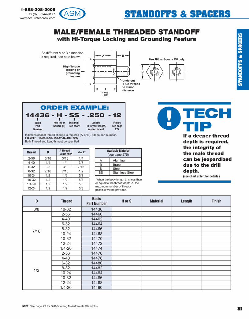
MALE/FEMALE THREADED STANDOFFwith Hi-Torque Locking and Grounding Feature
If a different A or B dimension,is required, see note below.
NOTE: See page 29 for Self-Forming Male/Female Standof fs.
A AluminumB BrassS Steel
SS Stainless Steel
ORDER EXAMPLE:14400
BasicPart
Number
HHex (H) orSquare (S)
SSMaterial:See chart
.250Length:
Fill in your length,any increment
12Finish:
See page277
----
If dimensional or thread change is required (A or B), add to part number. EXAMPLE: 14400-H-SS-.250-12 (B=440 x 3/8)Both Thread and Length must be specified.
D ThreadBasic
Part NumberH or S Material Length Finish
2-56 3/16 3/16 1/44-40 1/4 1/4 3/86-32 3/8 3/8 7/168-32 7/16 7/16 1/210-24 1/2 1/2 5/810-32 1/2 1/2 5/81/4-20 1/2 1/2 5/812-24 1/2 1/2 5/8
Thread B A Thread Depth Min* Min. L*
! TECHTIPIf a deeper threaddepth is required,the integrity of the male thread can be jeopardized due to the drilldepth. (see chart at left for details )
*When the body length L is less thanor equal to the thread depth A, themaximum number of threadspossible will be provided.
ST
AN
DO
FFS
&S
PAC
ER
S
31
1-888-208-2008Fax (973) 244-9177
www.accuratescrew.com STANDOFFS & SPACERS
3/8 10-32 144362-56 144604-40 144626-32 144648-32 144667/16 10-24 1446810-32 1447012-24 144721/4-20 144742-56 144764-40 144786-32 14480
1/2 8-32 1448210-24 1448410-32 1448612-24 144881/4-20 14490
MALE/FEMALE THREADED STANDOFFwith Hi-Torque Locking and Grounding Feature
If a different A or B dimension,is required, see note below.
NOTE: See page 29 for Self-Forming Male/Female Standof fs.
ORDER EXAMPLE:14436
BasicPart
Number
HHex (H) orSquare (S)
SSMaterial:See chart
.250Length:
Fill in your length,any increment
12Finish:
See page277
----
If dimensional or thread change is required (A or B), add to part number. EXAMPLE: 14436-H-SS-.250-12 (B=440 x 3/8)Both Thread and Length must be specified.
D ThreadBasic
Part NumberH or S Material Length Finish
Available Material(see page 275)
A AluminumB BrassS Steel
SS Stainless Steel
2-56 3/16 3/16 1/44-40 1/4 1/4 3/86-32 3/8 3/8 7/168-32 7/16 7/16 1/210-24 1/2 1/2 5/810-32 1/2 1/2 5/81/4-20 1/2 1/2 5/812-24 1/2 1/2 5/8
Thread B A Thread Depth Min* Min. L*
! TECHTIPIf a deeper threaddepth is required,the integrity of the male thread can be jeopardized due to the drilldepth. (see chart at left for details )
*When the body length L is less thanor equal to the thread depth A, themaximum number of threadspossible will be provided.

ST
AN
DO
FFS &
SPA
CE
RS
32
1-888-208-2008Fax (973) 244-9177www.accuratescrew.comSTANDOFFS & SPACERS
DBasicPart
Number SizeB
LengthA Thd
Depth Min*Outside Dia
± 1/64 Min Max Min Max
Thread Data CaptiveWasher
Internal Tooth Lock WasherOutside Dia Thickness
1/4
5/16
3/8
14021 2-56 3/16 3/16 1/4 .175 .200 .010 .01514031 4-40 1/4 1/4 5/16 .255 .270 .015 .01914041 6-32 3/8 3/8 5/16 .275 .295 .017 .02114051 8-32 7/16 7/16 3/8 .325 .340 .018 .02314061 2-56 3/16 3/16 3/8 .175 .200 .010 .01514071 4-40 1/4 1/4 3/8 .255 .270 .015 .01914081 6-32 3/8 3/8 3/8 .275 .295 .017 .02114091 8-32 7/16 7/16 3/8 .325 .340 .018 .02314101 10-32 1/2 1/2 7/16 .365 .381 .020 .02514111 2-56 3/16 3/16 7/16 .175 .200 .010 .01514121 4-40 1/4 1/4 7/16 .255 .270 .015 .01914131 6-32 3/8 3/8 7/16 .275 .295 .017 .02114141 8-32 7/16 7/16 7/16 .325 .340 .018 .02314151 10-32 1/2 1/2 7/16 .365 .381 .020 .025
MALE/FEMALE LOCKING THREADEDSTANDOFF ASSEMBLY
Material - Spring Steel perQQ-S-700
Finish - Cadmium Plate per QQ-P-416 (Clear)
B Brass, Composition 360 Brass conforming to ASTM B3
S Steel Low Carbon 1018 Carbon Steel conforming to ASTM 108 ASTM - A 569
SS Stainless Steel 18-8 Stainless Steel conforming to 302 - 304 Series AISI Type 302 or 305
Available Material
Standoff Captive Washer Internal Tooth Lock Washer
ORDER EXAMPLE:
If a different male Leng h (B) or a dif ferent internal thread depth in female A is required,add requirement to the part number.Example: 14021-H-.500-SS-A-12 (A = 4-40 x 1/4 deep)
- - - - -14021BasicPart
Number
HHex (H),
Round (R)or Square (S)
SSMaterial:See chart
.500Length:
Fill in your length,any increment
AAssembly
12Finish:
See page 277
*A dimension will be maximum depth (minimum or 1-1/2 threads).

ST
AN
DO
FFS
&S
PAC
ER
S
33
1-888-208-2008Fax (973) 244-9177
www.accuratescrew.com STANDOFFS & SPACERS
DBasicPart
Number SizeB
LengthA Thd
Depth Min*Outside Dia
± 1/64 Min Max Min Max
Thread Data CaptiveWasher
Internal Tooth Lock WasherOutside Dia Thickness
7/16
1/2
14161 2-56 3/16 3/1614171 4-40 1/4 1/414181 6-32 3/8 3/814191 8-32 7/16 7/1614211 10-32 1/2 1/214231 1/4-20 1/2 1/214241 2-56 3/16 3/1614251 4-40 1/4 1/414261 6-32 3/8 3/814271 8-32 7/16 7/1614291 10-32 1/2 1/214311 1/4-20 1/2 1/2
.175 .200 .010 .015
.255 .270 .015 .019
.275 .295 .017 .021
.325 .340 .018 .023
.365 .381 .020 .025
.460 .478 .023 .028
.175 .200 .010 .015
.255 .270 .015 .019
.275 .295 .017 .021
.325 .340 .018 .023
.365 .381 .020 .025
.460 .478 .023 .028
1/2
9/16
*A dimension will be maximum depth (minimum or 1-1/2 threads).
MALE/FEMALE LOCKING THREADEDSTANDOFF ASSEMBLY
Material - Spring Steel perQQ-S-700
B Brass, Composition 360 Brass conforming to ASTM B3S Steel Low Carbon 1018 Carbon Steel conforming to
ASTM 108 ASTM - A 569SS Stainless Steel 18-8 Stainless Steel conforming to
302 - 304 Series AISI Type 302 or 305
Available Material
Standoff Captive Washer Internal Tooth Lock Washer
ORDER EXAMPLE:
If a different male Leng h (B) or a dif ferent internal thread depth in female A is required,add requirement to the part number.Example: 14161-H-.500-SS-A-12 (A = 4-40 x 1/4 deep)
- - - - -14161BasicPart
Number
HHex (H),
Round (R)or Square (S)
SSMaterial:See chart
.500Length:
Fill in your length,any increment
AAssembly
12Finish:
See page 277

ST
AN
DO
FFS &
SPA
CE
RS
34
1-888-208-2008Fax (973) 244-9177www.accuratescrew.comSTANDOFFS & SPACERS
Thread A-B
DOUBLE-ENDED MALE STANDOFFS
Available Material (see page 275)
A Aluminum Ph** Phenolic (Paper)B Brass Phl** Phenolic (Linen)C Copper L** Polycarbonate (Lexan)S Steel PA** A.B.S.
SS Stainless Steel PP** P.V.C.N Nylon T TeflonD Delrin F** F ber
**Supplied in round only.
2-564-406-328-3210-2410-321/4-201/4-28
3/161/43/87/161/21/21/21/2
Natural 1Black 2Red 3Blue 4Purple 5Brown 6Orange 7Green 8Yellow 9
Color Code
(see page 109)
ORDER EXAMPLE:20500
BasicPart
Number
HHex (H),
Round (R) orSquare (S)
SSMaterial:See chart
.250Length:
Fill in your length,any increment
12Finish:
See page277
----
EXAMPLE FOR NYLON AND DELRIN PARTS: 20500-H-N-.250-2 BLACKChoose color from chart, otherwise Natural is provided.When A and B threads are dif ferent, specify both Thread and Leng h,add them to the closest part number . EXAMPLE: 20500-H-SS-.250-12 (A-4-40 X 1/4, B=6-32 X 3/8)
D x THD Basic Part Number H or R or S Material Length Finish
3/16 x 2-56 205003/16 x 4-40 205021/4 x 2-56 205041/4 x 4-40 205061/4 x 6-32 205081/4 x 8-32 20510
5/16 x 2-56 205125/16 x 4-40 205145/16 x 6-32 205165-16 x 8-32 205185/16 x 10-32 205203/8 x 2-56 205223/8 x 4-40 205243/8 x 6-32 205263/8 x 8-32 205283/8 x 10-32 205303/8 x 1/4-20 205323/8 x 1/4-28 20533
! TECH TIPAll standoffs and spacerscan be dimensionally customized to fityour application.

ST
AN
DO
FFS
&S
PAC
ER
S
35
1-888-208-2008Fax (973) 244-9177
www.accuratescrew.com STANDOFFS & SPACERS
Thread A-B
DOUBLE-ENDED MALE STANDOFFS
Available Material (see page 275)
A Aluminum Ph** Phenolic (Paper)B Brass Phl** Phenolic (Linen)C Copper L** Polycarbonate (Lexan)S Steel PA** A.B.S.
SS Stainless Steel PP** P.V.C.N Nylon T TeflonD Delrin F** F ber
**Supplied in round only.
2-564-406-328-3210-2410-321/4-201/4-28
3/161/43/87/161/21/21/21/2
Natural 1Black 2Red 3Blue 4Purple 5Brown 6Orange 7Green 8Yellow 9
Color Code
(see page 109)
ORDER EXAMPLE:20034
BasicPart
Number
HHex (H),
Round (R) orSquare (S)
SSMaterial:See chart
.250Length:
Fill in your length,any increment
12Finish:
See page277
----
EXAMPLE FOR NYLON AND DELRIN PARTS: 20034-H-N-.250-2 BLACKChoose color from chart, otherwise Natural is provided.When A and B threads are dif ferent, specify both Thread and Leng h,add them to the closest part number . EXAMPLE: 20034-H-SS-.250-12 (A-4-40 X 1/4, B=6-32 X 3/8)
D x THD Basic Part Number H or R or S Material Length Finish
7/16 x 2-56 200347/16 x 4-40 200367/16 x 6-32 200387/16 x 8-32 200407/16 x 10-24 200427/16 x 10-32 200447/16 x 1/4-20 200467/16 x 1/4-28 200481/2 x 2-56 200501/2 x 4-40 200521/2 x 6-32 200541/2 x 8-32 200561/2 x 10-24 200581/2 x 10-32 200601/2 x 1/4-20 200621/2 x 1/4-28 20064

D x THD Basic Part Number H or R or S Material Length Finish
3/16 x 2-56 206003/16 x 4-40 206021/4 x 2-56 206041/4 x 4-40 206061/4 x 6-32 206081/4 x 8-32 20610
5/16 x 2-56 206125/16 x 4-40 206145/16 x 6-32 206165/16 x 8-32 206185/16 x 10-32 206203/8 x 2-56 206223/8 x 4-40 206243/8 x 6-32 206263/8 x 8-32 206283/8 x 10-32 206303/8 x 1/4-20 206323/8 x 1/4-28 20634
ST
AN
DO
FFS &
SPA
CE
RS
36
1-888-208-2008Fax (973) 244-9177www.accuratescrew.comSTANDOFFS & SPACERS
Thread A-B
DOUBLE-ENDED MALE STANDOFFS with Hi-Torque Feature
ORDER EXAMPLE:20600
BasicPart
Number
HHex (H),
Round (R) orSquare (S)
SSMaterial:See chart
.250Length:
Fill in your length,any increment
12Finish:
See page277
----
When A and B threads are dif ferent, specify both Thread and Leng h, add them to the closest part number . EXAMPLE: 20600-H-SS-.250-12 (A-4-40 X 1/4, B=6-32 X 3/8)
(see page 109)
Available Material (see page 275)
A AluminumB BrassS Steel
SS Stainless Steel
2-56 3/164-40 1/46-32 3/88-32 7/16
10-24 1/210-32 1/21/4-20 1/21/4-28 1/2

ST
AN
DO
FFS
&S
PAC
ER
S
37
1-888-208-2008Fax (973) 244-9177
www.accuratescrew.com STANDOFFS & SPACERS
D x THD Basic Part Number H or R or S Material Length Finish
7/16 x 2-56 206367/16 x 4-40 206387/16 x 6-32 206407/16 x 8-32 206427/16 x 10-24 206447/16 x 10-32 206467/16 x 1/4-20 206487/16 x 1/4-28 206501/2 x 2-56 206521/2 x 4-40 206541/2 x 6-32 206561/2 x 8-32 206581/2 x 10-24 206601/2 x 10-32 206621/2 x 1/4-20 206641/2 x 1/4-28 20666
Thread A-B
DOUBLE-ENDED MALE STANDOFFS with Hi-Torque Feature
ORDER EXAMPLE:20636
BasicPart
Number
HHex (H),
Round (R) orSquare (S)
SSMaterial:See chart
.250Length:
Fill in your length,any increment
12Finish:
See page277
----
When A and B threads are dif ferent, specify both Thread and Leng h, add them to the closest part number . EXAMPLE: 20636-H-SS-.250-12 (A-4-40 X 1/4, B=6-32 X 3/8)
(see page 109)
Available Material (see page 275)
A AluminumB BrassS Steel
SS Stainless Steel
2-56 3/164-40 1/46-32 3/88-32 7/16
10-24 1/210-32 1/21/4-20 1/21/4-28 1/2
! TECH TIPBe sure to check out our new 3D CAD model repository atwww.accuratescrew.com. Each model is custom generatedas per your specifications.

ST
AN
DO
FFS &
SPA
CE
RS
38
1-888-208-2008Fax (973) 244-9177www.accuratescrew.comSTANDOFFS & SPACERS
KNURLED MALE/FEMALE THREADED STANDOFF
5/32 x 2-56 1139185/32 x 4-40 1139203/16 x 2-56 1139223/16 x 4-40 1139243/16 x 6-32 1139261/4 x 2-56 1139281/4 x 4-40 1139301/4 x 6-32 1139321/4 x 8-32 113934
5/16 x 2-56 1139365/16 x 4-40 1139385/16 x 6-32 1139405/16 x 8-32 1139425/16 x 10-32 1139443/8 x 2-56 1139463/8 x 4-40 1139483/8 x 6-32 1139503/8 x 8-32 1139523/8 x 10-32 113954
7/16 x 2-56 1139567/16 x 4-40 1139587/16 x 6-32 1139607/16 x 10-32 1139621/2 x 4-40 1139641/2 x 6-32 1139661/2 x 8-32 1139681/2 x 10-32 1139721/2 x 1/4-20 113974
Thread B A Thread Depth Min*
2-56 3/16 3/164-40 1/4 1/46-32 3/8 3/88-32 7/16 7/1610-32 1/2 1/21/4-20 1/2 1/2
*When the body length L is less than or equalto the thread depth A, the maximum of threadspossible will be provided.
Available Material (see page 275)
A AluminumB BrassS Steel
SS Stainless Steel
(see page 109)
ORDER EXAMPLE:- - -113918
BasicPart
Number
AMaterial:See chart
.500Length:
Fill in your length,any increment
1Finish:
See page 277
If different Thread or Length is required, add to the closest part number .EXAMPLE: 113918-A-.500-1 MOD (B= 4-40 x 1/2 Lg.)
OD x ThdDiameter before Knurl
BasicPart Number
Material Length Finish

ST
AN
DO
FFS
&S
PAC
ER
S
39
1-888-208-2008Fax (973) 244-9177
www.accuratescrew.com STANDOFFS & SPACERS
MALE/FEMALE THREADED SPACERwith Self-Locating Feature
1/4
5/16
3/8
1/2
5/8
2-56 38664-40 38688-32 38726-32 38768-32 387810-32 38806-32 38828-32 388410-32 38861/4-20 38881/4-28 38906-32 38928-32 389410-32 38961/4-20 38981/4-28 3900
Boardor Panel
Thickness
DRecommendedShank Length
1/32 .0251/16 .0553/32 .0851/8 .1183/16 .1801/4 .240
Thread A Min
2-56 3/16 3/8 .188 .2304-40 1/4 3/8 .188 .2306-32 3/8 3/8 .234 .2758-32 7/16 3/8 .234 .27510-32 1/2 3/8 .312 .35010-24 1/2 3/8 .312 .3501/4-20 1/2 1/2 .375 .4151/4-28 1/2 1/2 .375 .415
*When L dimension is equal to or smaller than A, the depth will be maximum possible or a minimum of 1-1/2 threads, whichever is greater.
B C E +.005
A Aluminum
B Brass
S Steel
SS Stainless Steel
N Nylon
D Delrin
Available Material (see page 275)
Natural 1Black 2Red 3Blue 4Purple 5Brown 6Orange 7Green 8Yellow 9
NYLON AND DELRIN
Color Code+.000-.003
(see page 109)
ORDER EXAMPLE:
Any one dimension change, add to part number . EXAMPLE: 3866-H-.500-.055-A-3 (MOD B=250) FOR NYLON AND DELRIN PARTS: Choose color from chart, otherwise Natural is provided.Part number for nylon and Delrin parts: EXAMPLE: 3866-H-.500-.055-N-3 RED
- - - - -3866BasicPart
Number
HHex (H) orRound (R)
.055D
Dim.
.500Length:
Fill in your length,any increment
AMaterial:See chart
3Finish:
See page 277
OD or Hex Thread Basic Part No. Hex or Round L* D Material Finish

ST
AN
DO
FFS &
SPA
CE
RS
40
1-888-208-2008Fax (973) 244-9177www.accuratescrew.comSTANDOFFS & SPACERS
MALE/FEMALE LOCKING THREADED STANDOFF
2-56 3/16 5/324-40 1/4 3/166-32 3/8 1/48-32 7/16 3/8
10-24 1/2 3/810-32 1/2 3/8
Thread
Washer SizeA
InsideDiameter
B Outside
Diameter
CThickness
Min Max MaxMin MaxMin
2-564-406-328-3210-2410-32
.115
.141
.168
.195
.258
.258
.123
.150
.176
.204
.267
.267
.245
.305
.365
.395
.494
.494
.260
.320
.381
.410
.510
.510
.015
.016
.018
.020
.023
.023
.019
.022
.029
.025
.028
.028
Lock WasherMaterial Finish
S Steel - 1040/1060 Zinc Chrome Clear
SS Stainless Steel - 410 NONE
Male/Female StandoffAvailable Material(see page 275)
*When the body length L is less than orequal to the thread depth A, themaximum of threads possible will beprovided.
2-563/16 4-402-561/4 4-402-564-40
5/16 6-328-3210-322-564-40
3/8 6-328-3210-322-564-406-32
7/16 8-3210-2410-3212-242-564-40
1/2 6-328-3210-2410-3212-24
Thread BasicPart Number
OD
NOTE: For depth of hread, see page 281.
14000140101402014030140601407014080140901410014110141201413014140141501416014170141801419014200142101422014240142501426014270142801429014300
A AluminumB BrassC CopperS Steel
SS Stainless Steel
ORDER EXAMPLE:
NOTE: To order Lock Washer in Steel (1040/1060) just add LS to end of part number. EXAMPLE: 14000-H-SS-.250-LS-12
14000BasicPart
Number
HHex (H),
Round (R)or Square (S)
SSStandoffMaterial:See chart
.250Length L:
Fill in your length,any increment
LSSLock Washer
Material:Stainless (LSS)
or Steel (LS)
12Finish:
See page 277
- - - - -
! TECHTIPOur new in-housepassivation process,certified to QQP35C-AMS2700B-MIL F14072D, furtherimproves our leadtimes.
Thread BA Thread
Depth Min*
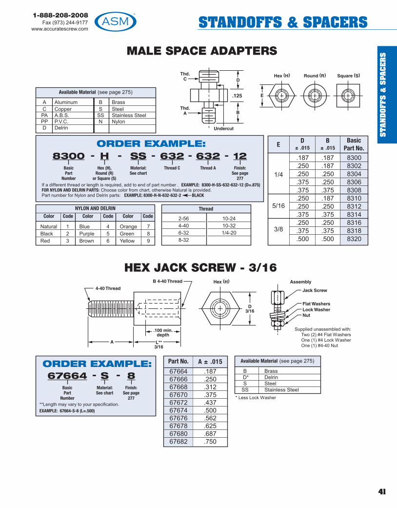
ST
AN
DO
FFS
&S
PAC
ER
S
41
1-888-208-2008Fax (973) 244-9177
www.accuratescrew.com STANDOFFS & SPACERS
MALE SPACE ADAPTERS
ED
± .015B
± .015Basic
Part No.
1/4
5/16
3/8
.187
.250
.250
.375
.375
.250
.250
.375
.250
.375
.500
.187
.187
.250
.250
.375
.187
.250
.375
.250
.375
.500
83008302830483068308831083128314831683188320
Thread
2-564-406-328-32
10-2410-321/4-20
Supplied unassembled with:Two (2) #4 Flat WashersOne (1) #4 Lock WasherOne (1) #4-40 Nut
Part No. A ± .015
67664676666766867670676726767467676676786768067682
.187
.250
.312
.375
.437
.500
.562
.625
.687
.750
B BrassD* DelrinS Steel
SS Stainless Steel
Available Material (see page 275)
* Less Lock Washer
HEX JACK SCREW - 3/16
A Aluminum B BrassC Copper S SteelPA A.B.S. SS Stainless SteelPP P.V.C. N NylonD Delrin
Available Material (see page 275)
Natural 1Black 2Red 3
Blue 4Purple 5Brown 6
Orange 7Green 8Yellow 9
NYLON AND DELRIN
Color Code Color Code Color Code
ORDER EXAMPLE:
If a different thread or length is required, add to end of part number . EXAMPLE: 8300-H-SS-632-632-12 (D=.875)FOR NYLON AND DELRIN PARTS: Choose color from chart, otherwise Natural is provided.Part number for Nylon and Delrin parts: EXAMPLE: 8300-H-N-632-632-2 BLACK
- - - - -8300BasicPart
Number
HHex (H),
Round (R)or Square (S)
SSMaterial:See chart
632Thread C
632Thread A
12Finish:
See page277
ORDER EXAMPLE:
**Length may vary to your specification. EXAMPLE: 67664-S-8 (L=.500)
67664BasicPart
Number
8Finish:
See page277
-SMaterial:See chart
-

ST
AN
DO
FFS &
SPA
CE
RS
42
1-888-208-2008Fax (973) 244-9177www.accuratescrew.comSTANDOFFS & SPACERS
A AluminumB BrassS Steel
SS Stainless SteelN NylonC CopperD Delrin
Available Material (see page 275)
MALE STANDOFF - SHOULDER TYPE
ROUND ONLY
ORDER EXAMPLE:
Any one dimension change, add to the end of part number .Example: 3920-H-SS-12 (T=.200)Screw Driver Slot is available, add SDS to part number . Example: 3920-H-SS-12 SDS
3920Basic
Part Number
HHex (H),
Round (R) orSquare (S)
SSMaterial:See chart
12Finish:
See page 277
- - -
PartNumber
A +.000–.003
B± .003
COD
T Thread LengthPart
NumberA +.000
–.003B
± .003C
ODT Thread Length
3920 .1245 .125 1/4 .125 440 5/323922 .1245 .187 1/4 .125 440 5/323924 .1245 .250 1/4 .125 440 5/323925 .1245 .312 1/4 .125 440 5/323927 .1245 .437 1/4 .125 440 5/323928 .1245 .500 1/4 .125 440 5/323930 .156 .125 9/32 .125 6-32 3/163932 .156 .187 9/32 .125 6-32 3/163934 .156 .250 9/32 .125 6-32 3/163936 .156 .312 9/32 .125 6-32 3/163937 .156 .375 9/32 .125 6-32 3/163938 .156 .437 9/32 .125 6-32 3/163939 .156 .500 9/32 .125 6-32 3/163940 .156 .562 9/32 .125 6-32 3/163941 .156 .625 9/32 .125 6-32 3/163942 .156 .687 9/32 .125 6-32 3/163943 .156 .750 9/32 .125 6-32 3/163948 .187 .125 5/16 .156 8-32 3/163950 .187 .187 5/16 .156 8-32 3/163951 .187 .250 5/16 .156 8-32 3/163952 .187 .312 5/16 .156 8-32 3/163954 .187 .375 5/16 .156 8-32 3/163955 .187 .437 5/16 .156 8-32 3/163956 .187 .500 5/16 .156 8-32 3/163958 .187 .562 5/16 .156 8-32 3/163960 .187 .625 5/16 .156 8-32 3/163961 .187 .687 5/16 .156 8-32 3/163962 .187 .750 5/16 .156 8-32 3/163964 .187 .875 5/16 .156 8-32 3/163966 .187 1.000 5/16 .156 8-32 3/163968 .187 1.250 5/16 .156 8-32 3/163970 .187 1.375 5/16 .156 8-32 3/163972 .187 1.500 5/16 .156 8-32 3/16
3973 .250 .125 3/8 .187 1032 1/43974 .250 .187 3/8 .187 1032 1/43975 .250 .250 3/8 .187 1032 1/43976 .250 .312 3/8 .187 1032 1/43977 .250 .437 3/8 .187 1032 1/43978 .250 .500 3/8 .187 1032 1/43979 .250 .562 3/8 .187 1032 1/43980 .250 .625 3/8 .187 1032 1/43981 .250 .687 3/8 .187 1032 1/43982 .250 .750 3/8 .187 1032 1/43983 .250 .875 3/8 .187 1032 1/43984 .250 1.000 3/8 .187 1032 1/43985 .250 1.250 3/8 .187 1032 1/43986 .250 1.375 3/8 .187 1032 1/43987 .250 1.500 3/8 .187 1032 1/43989 .312 .125 1/2 .250 1/4-20 7/163990 .312 .187 1/2 .250 1/4-20 7/163991 .312 .250 1/2 .250 1/4-20 7/163992 .312 .312 1/2 .250 1/4-20 7/163993 .312 .437 1/2 .250 1/4-20 7/163994 .312 .500 1/2 .250 1/4-20 7/163995 .312 .562 1/2 .250 1/4-20 7/163996 .312 .625 1/2 .250 1/4-20 7/163997 .312 .687 1/2 .250 1/4-20 7/163998 .312 .750 1/2 .250 1/4-20 7/163999 .312 .875 1/2 .250 1/4-20 7/164000 .312 1.000 1/2 .250 1/4-20 7/164001 .312 1.250 1/2 .250 1/4-20 7/164002 .312 1.375 1/2 .250 1/4-20 7/164003 .312 1.500 1/2 .250 1/4-20 7/16
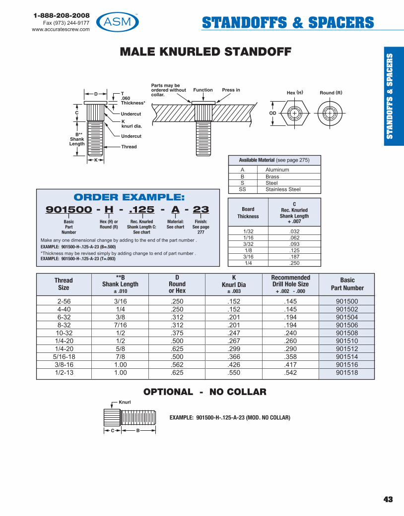
ST
AN
DO
FFS
&S
PAC
ER
S
43
1-888-208-2008Fax (973) 244-9177
www.accuratescrew.com STANDOFFS & SPACERS
MALE KNURLED STANDOFF
BoardThickness
C Rec. KnurledShank Length
+ .007
1/32 .0321/16 .0623/32 .0931/8 .1253/16 .1871/4 .250
2-564-406-328-3210-321/4-201/4-205/16-183/8-161/2-13
3/161/43/87/161/21/25/87/81.001.00
.250
.250
.312
.312
.375
.500
.625
.500
.562
.625
.152
.152
.201
.201
.247
.267
.299
.366
.426
.550
.145
.145
.194
.194
.240
.260
.290
.358
.417
.542
901500901502901504901506901508901510901512901514901516901518
OPTIONAL - NO COLLAR
EXAMPLE: 901500-H-.125-A-23 (MOD. NO COLLAR)
A AluminumB BrassS Steel
SS Stainless Steel
Available Material (see page 275)
ORDER EXAMPLE:901500
BasicPart
Number
HHex (H) orRound (R)
.125Rec. Knurled
Shank Length C:See chart
AMaterial:See chart
23Finish:
See page277
----
Make any one dimensional change by adding to the end of the part number .EXAMPLE: 901500-H-.125-A-23 (B=.500)*Thickness may be revised simply by adding change to end of part number .EXAMPLE: 901500-H-.125-A-23 (T=.093)
ThreadSize
**BShank Length
± .010
DRound or Hex
K Knurl Dia
± .003
RecommendedDrill Hole Size
+ .002 - .000
Basic Part Number

ST
AN
DO
FFS &
SPA
CE
RS
44
1-888-208-2008Fax (973) 244-9177www.accuratescrew.comSTANDOFFS & SPACERS
DOUBLE-ENDED MALE KNURLED STANDOFF
2-564-406-328-3210-321/4-201/4-205/16-183/8-161/2-13
3/161/43/87/161/21/25/87/81.001.00
.250
.250
.312
.312
.375
.500
.625
.500
.562
.625
.152
.152
.201
.201
.247
.267
.299
.366
.426
.550
.145
.145
.194
.194
.240
.260
.290
.358
.417
.542
901501901503901505901507901509901511901513901515901517901519
BoardThickness
C Rec. KnurledShank Length
+.007
1/32 .0321/16 .0623/32 .0931/8 .1253/16 .1871/4 .250
A AluminumB BrassS Steel
SS Stainless Steel
Available Material (see page 275)
ORDER EXAMPLE:901501
BasicPart
Number
HHex (H) orRound (R)
.125Rec. Knurled
Shank Length C:See chart
AMaterial:See chart
23Finish:
See page277
----
Make any one dimensional change by adding to the end of the part number .EXAMPLE: 901501-H-.125-A-23 (B=.250)**Thickness may be revised simply by adding change to end of part number .EXAMPLE: 901501-H-.125-A-23 (T=.093)
ThreadSize
A & BShank Length
± .010
DRound or Hex
K Knurl Dia
± .003
RecommendedDrill Hole Size
+.002 -.000
Basic Part Number
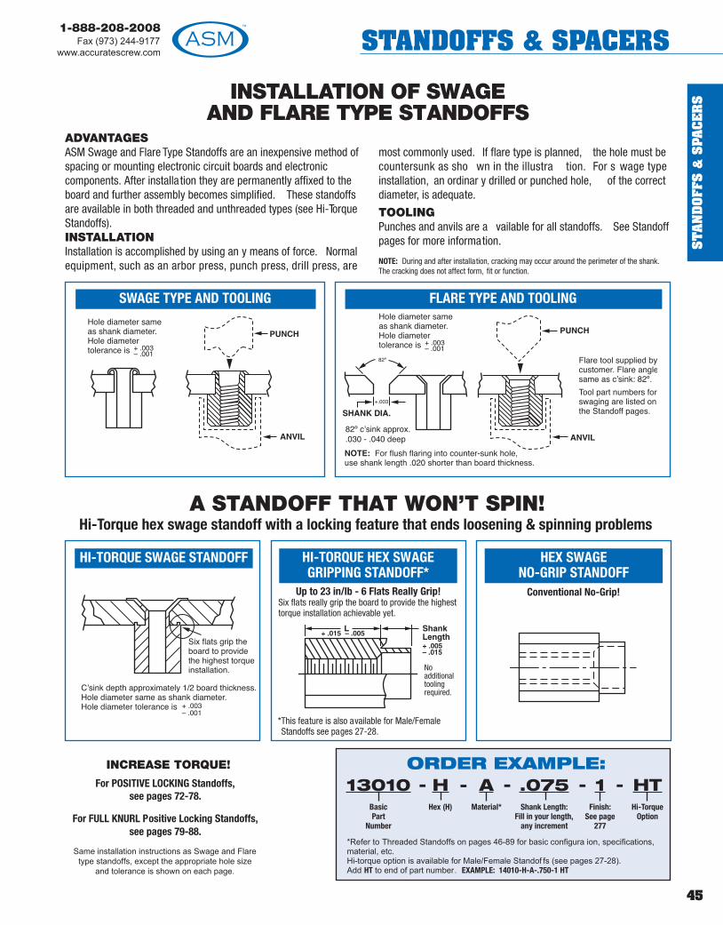
ST
AN
DO
FFS
&S
PAC
ER
S
45
1-888-208-2008Fax (973) 244-9177
www.accuratescrew.com STANDOFFS & SPACERS
HI-TORQUE SWAGE STANDOFF
INCREASE TORQUE!
For POSITIVE LOCKING Standoffs,see pages 72-78.
For FULL KNURL Positive Locking Standoffs,see pages 79-88.
Same installation instructions as Swage and Flare type standoffs, except the appropriate hole size
and tolerance is shown on each page.
INSTALLATION OF SWAGEAND FLARE TYPE STANDOFFS
A STANDOFF THAT WON’T SPIN!Hi-Torque hex swage standoff with a locking feature that ends loosening & spinning problems
*This feature is also available for Male/FemaleStandoffs see pages 27-28.
ADVANTAGESASM Swage and Flare Type Standoffs are an inexpensive method ofspacing or mounting electronic circuit boards and electroniccomponents. After installa tion they are permanently affixed to theboard and further assembly becomes simplified. These standoffsare available in both threaded and unthreaded types (see Hi-TorqueStandoffs).INSTALLATIONInstallation is accomplished by using an y means of force. Normalequipment, such as an arbor press, punch press, drill press, are
most commonly used. If flare type is planned, the hole must becountersunk as sho wn in the illustra tion. For s wage typeinstallation, an ordinar y drilled or punched hole, of the correctdiameter, is adequate.
TOOLINGPunches and anvils are a vailable for all standoffs. See Standoffpages for more information.
NOTE: During and after installation, cracking may occur around the perimeter of the shank.The cracking does not affect form, fit or function.
ORDER EXAMPLE:
*Refer to Threaded Standoffs on pages 46-89 for basic configura ion, specifications,material, etc. Hi-torque option is available for Male/Female Standof fs (see pages 27-28).Add HT to end of part number. EXAMPLE: 14010-H-A-.750-1 HT
- - - -13010BasicPart
Number
HHex (H)
AMaterial*
.075Shank Length:
Fill in your length,any increment
1Finish:
See page277
HTHi-Torque
Option
-
SWAGE TYPE AND TOOLING FLARE TYPE AND TOOLING
HI-TORQUE HEX SWAGEGRIPPING STANDOFF*
Up to 23 in/lb - 6 Flats Really Grip!Six flats really grip the board to provide the highesttorque installation achievable yet.
HEX SWAGENO-GRIP STANDOFF
Conventional No-Grip!
Noadditionaltoolingrequired.

ST
AN
DO
FFS &
SPA
CE
RS
46
1-888-208-2008Fax (973) 244-9177www.accuratescrew.comSTANDOFFS & SPACERS
L Length Thread BasicPart Number H or R Material Shank Length Finish
1/8 0-80 110103/16 0-80 110121/4 0-80 110145/16 0-80 110163/8 0-80 110187/16 0-80 110201/2 0-80 110229/16 0-80 110245/8 0-80 11026
11/16 0-80 110283/4 0-80 11030
13/16 0-80 110327/8 0-80 11034
15/16 0-80 110361 0-80 11038
1-3/16 0-80 110401-1/4 0-80 110421-3/8 0-80 110441-1/2 0-80 110461-3/4 0-80 11048
2 0-80 11050
CLEAR HOLE STANDOFFS
EXAMPLE: P - 1 PUNCH HA - 40 ANVIL
SWAGE STANDOFFS - THREADED & CLEAR HOLE1/8" Hex or Round - 0-80 Thd.
NOTE: Where L dimension is 1/2 or longer, see page 281 for depth of thread.
RA -10 HA-40 1/8-3/16RA-11 HA-41 1/4-7/16RA-12 HA-42 1/2-11/16RA-13 HA-43 3/4 & up
Swage Tooling
P-1
Punch Part Number
Anvil Part NumberRound He x
Length
Available ID and Appropriate CodeID Code Letter
.070 P
Prefix letter code to part number.EXAMPLE: P11010-H-SS-.105-12
+.010–.000
BoardThickness
RecommendedShank Length
for Swage
1/32 .0751/16 .1053/32 .1351/8 .1653/16 .2301/4 .290
A Aluminum Ph** Phenolic (Paper)B Brass Phl** Phenolic (Linen)C Copper L** Polycarbonate (Lexan)S Steel PA** A.B.S
SS Stainless Steel PP** P.V.CN Nylon T TeflonD Delrin F** F ber
**Supplied in round only.
Available Material (see page 275)
.070 - ID
ORDER EXAMPLE:11010
BasicPart
Number
HHex (H) orRound (R)
SSMaterial:See chart
.105Shank Length:See chart orfill in yourown length
12Finish:
See page277
----
*L dimension may be changed, add required length to the closest part number .EXAMPLE: 11022-R-SS-.105-12 (L=.525)
See page 281 for dep h of thread.See page 45 for installation instructions.
1/8 .090
Ct. Bore .063
+ .000– .003
+ .003– .000 0-80
Thread

ST
AN
DO
FFS
&S
PAC
ER
S
47
1-888-208-2008Fax (973) 244-9177
www.accuratescrew.com STANDOFFS & SPACERS
L Length Thread BasicPart Number H or R Material Shank Length Finish
1/8 2-56 210103/16 2-56 210201/4 2-56 210305/16 2-56 210403/8 2-56 210507/16 2-56 210521/2 2-56 210549/16 2-56 210565/8 2-56 21058
11/16 2-56 210603/4 2-56 21062
13/16 2-56 210647/8 2-56 21066
15/16 2-56 210681 2-56 21070
1-3/16 2-56 210721-1/4 2-56 210741-3/8 2-56 210761-1/2 2-56 210781-3/4 2-56 21080
2 2-56 21082
CLEAR HOLE STANDOFFS
EXAMPLE: P - 2 PUNCH HA - 44 ANVIL
SWAGE STANDOFFS - THREADED & CLEAR HOLE5/32" Hex or Round - 2-56 Thd.
NOTE: Where L dimension is 1/2 or longer, see page 281 for depth of thread.
RA -14 HA-44 1/8-3/16RA-15 HA-45 1/4-7/16RA-16 HA-46 1/2-11/16RA-17 HA-47 3/4 & up
Swage Tooling
P-2
Punch Part Number
Anvil Part NumberRound He x
Length
Available ID and Appropriate Code
ID Code Letter
.070 P
.091 QPrefix letter code to part number.EXAMPLE: P21010-H-SS-.105-12
+.010–.000
BoardThickness
RecommendedShank Length
for Swage
1/32 .0751/16 .1053/32 .1351/8 .1653/16 .2301/4 .290
A Aluminum Ph** Phenolic (Paper)B Brass Phl** Phenolic (Linen)C Copper L** Polycarbonate (Lexan)S Steel PA** A.B.S
SS Stainless Steel PP** P.V.CN Nylon T TeflonD Delrin F** F ber
**Supplied in round only.
Available Material (see page 275)
.070 - IDORDER EXAMPLE:21010
BasicPart
Number
HHex (H) orRound (R)
SSMaterial:See chart
.105Shank Length:See chart orfill in yourown length
12Finish:
See page277
----
*L dimension may be changed, add required length to the closest part number .EXAMPLE: 21054-R-SS-.105-12 (L=.525)
See page 281 for depth of thread.See page 45 for installation instructions.
5/32 .125
Ct. Bore .098
+ .000– .003
+ .003– .000 2-56
Thread

ST
AN
DO
FFS &
SPA
CE
RS
48
1-888-208-2008Fax (973) 244-9177www.accuratescrew.comSTANDOFFS & SPACERS
L Length Thread BasicPart Number H or R or S Material Shank Length Finish HT Option
SWAGE STANDOFFS - THREADED & CLEAR HOLE3/16" Hex, Round or Square - 2-56 Thd.
NOTE: Where L dimension is 1/2 or longer, see page 281 for depth of thread.
EXAMPLE: P - 3 PUNCH HA - 48 ANVIL
1/8 2-56 311103/16 2-56 311151/4 2-56 311205/16 2-56 311253/8 2-56 311307/16 2-56 311351/2 2-56 311409/16 2-56 311455/8 2-56 31150
11/16 2-56 311553/4 2-56 31160
13/16 2-56 311627/8 2-56 311651 2-56 31170
1-3/16 2-56 311721-1/4 2-56 311741-3/8 2-56 311761-1/2 2-56 311781-3/4 2-56 31180
2 2-56 31182
CLEAR HOLE STANDOFFS
Available ID and Appropriate CodeID Code Letter
.070 P
.091 Q
+.010–.000
RA -18 HA-48 1/8-3/16RA-19 HA-49 1/4-7/16RA-20 HA-50 1/2-11/16RA-21 HA-51 3/4 & up
Swage Tooling
P-3
Punch Part Number
Anvil Part NumberRound He x
Length
BoardThickness
RecommendedShank Length
for Swage
1/32 .0751/16 .1053/32 .1351/8 .1653/16 .2301/4 .290
A Aluminum Ph** Phenolic (Paper)B Brass Phl** Phenolic (Linen)C Copper L** Polycarbonate (Lexan)S Steel PA** A.B.S
SS Stainless Steel PP** P.V.CN Nylon T TeflonD Delrin F** Fiber
**Supplied in round only.
Available Material (see page 275)
See page 281 for depth of hread.See page 45 for installation instructions.
3/16 .125
Ct. Bore .104
+ .002– .001
+ .002– .001 2-56
Thread
ORDER EXAMPLE:31110
BasicPart
Number
HHex (H),
Round (R)or Square (S)
SSMaterial:See chart
.105Shank Length:See chart orfill in yourown length
12Finish:
See page277
----
*L dimension may be changed, add required length to the closest part number .EXAMPLE: 31140-R-SS-.105-12 (L=.525)
HTHi-Torque
Option:See page
45
-
Prefix letter code to part number.EXAMPLE: P31110-H-SS-.105-12
.070 - ID

ST
AN
DO
FFS
&S
PAC
ER
S
49
1-888-208-2008Fax (973) 244-9177
www.accuratescrew.com STANDOFFS & SPACERS
L Length Thread BasicPart Number H or R or S Material Shank Length Finish HT Option
SWAGE STANDOFFS - THREADED & CLEAR HOLE3/16" Hex, Round or Square - 3-48 Thd.
NOTE: Where L dimension is 1/2 or longer, see page 281 for depth of thread.
1/8 3-48 411103/16 3-48 411151/4 3-48 411205/16 3-48 411253/8 3-48 411307/16 3-48 411351/2 3-48 411409/16 3-48 411455/8 3-48 41150
11/16 3-48 411553/4 3-48 41160
13/16 3-48 411627/8 3-48 411651 3-48 41170
1-1/4 3-48 411721-1/2 3-48 411741-3/4 3-48 41176
2 3-48 41178
EXAMPLE: P - 3 PUNCH HA - 48 ANVIL
RA -18 HA-48 1/8-3/16RA-19 HA-49 1/4-7/16RA-20 HA-50 1/2-11/16RA-21 HA-51 3/4 & up
Swage Tooling
P-3
Punch Part Number
Anvil Part NumberRound He x
Length
BoardThickness
RecommendedShank Length
for Swage 1/32 .0751/16 .1053/32 .1351/8 .1653/16 .2301/4 .290
A Aluminum Ph** Phenolic (Paper)B Brass Phl** Phenolic (Linen)C Copper L** Polycarbonate (Lexan)S Steel PA** A.B.S
SS Stainless Steel PP** P.V.CN Nylon T TeflonD Delrin F** Fiber
**Supplied in round only.
Available Material (see page 275)
See page 281 for depth of thread.See page 45 for installation instructions.
3/16 .125
Ct. Bore .104
+ .000– .003
+ .002– .001 3-48
Thread
ORDER EXAMPLE:41110
BasicPart
Number
HHex (H),
Round (R)or Square (S)
SSMaterial:See chart
.105Shank Length:See chart orfill in yourown length
12Finish:
See page277
----
*L dimension may be changed, add required length to the closest part number .EXAMPLE: 41140-R-SS-.105-12 (L=.525)
HTHi-Torque
Option:See page
45
-
CLEAR HOLE STANDOFFS
Available ID and Appropriate CodeID Code Letter
.070 P
.091 Q
+.010–.000
Prefix letter code to part number.EXAMPLE: P41110-H-SS-.105-12
.070 - ID

ST
AN
DO
FFS &
SPA
CE
RS
50
1-888-208-2008Fax (973) 244-9177www.accuratescrew.comSTANDOFFS & SPACERS
L Length Thread BasicPart Number H or R or S Material Shank Length Finish HT Option
1/8 2-56 310105/32 2-56 310123/16 2-56 310151/4 2-56 310205/16 2-56 310253/8 2-56 310307/16 2-56 310351/2 2-56 310409/16 2-56 310455/8 2-56 31050
11/16 2-56 310553/4 2-56 31060
13/16 2-56 310627/8 2-56 31065
15/16 2-56 310671 2-56 31070
1-3/16 2-56 310721-1/4 2-56 310741-3/8 2-56 310761-1/2 2-56 310781-3/4 2-56 31080
2 2-56 31082
NOTE: Where L dimension is 1/2 or longer, see page 281 for depth of thread.
SWAGE STANDOFFS - THREADED & CLEAR HOLE3/16" Hex, Round or Square - 2-56 Thd.
EXAMPLE: P - 3 PUNCH HA - 48 ANVIL
RA -18 HA-48 1/8-3/16RA-19 HA-49 1/4-7/16RA-20 HA-50 1/2-11/16RA-21 HA-51 3/4 & up
Swage Tooling
P-3
Punch Part Number
Anvil Part NumberRound He x
Length
CLEAR HOLE STANDOFFS
Available ID and Appropriate CodeID Code Letter
.070 P
.091 Q
.115 U
+.010–.000
BoardThickness
RecommendedShank Length
for Swage
1/32 .0751/16 .1053/32 .1351/8 .1653/16 .2301/4 .290
A Aluminum Ph** Phenolic (Paper)B Brass Phl** Phenolic (Linen)C Copper L** Polycarbonate (Lexan)S Steel PA** A.B.S
SS Stainless Steel PP** P.V.CN Nylon T TeflonD Delrin F** Fiber
**Supplied in round only.
Available Material (see page 275)
See page 281 for depth of thread.See page 45 for installation instructions.
3/16 .139
Ct. Bore .109
+ .000– .003
+ .002– .001 2-56
Thread
ORDER EXAMPLE:31010
BasicPart
Number
HHex (H),
Round (R)or Square (S)
SSMaterial:See chart
.105Shank Length:See chart orfill in yourown length
12Finish:
See page277
----
*L dimension may be changed, add required length to the closest part number .EXAMPLE: 31040-R-SS-.105-12 (L=.525)
HTHi-Torque
Option:See page
45
-
Prefix letter code to part number.EXAMPLE: P31010-H-SS-.105-12
.070 - ID

ST
AN
DO
FFS
&S
PAC
ER
S
51
1-888-208-2008Fax (973) 244-9177
www.accuratescrew.com STANDOFFS & SPACERS
L Length Thread BasicPart Number H or R or S Material Shank Length Finish HT Option
1/8 3-48 410103/16 3-48 410151/4 3-48 410205/16 3-48 410253/8 3-48 410307/16 3-48 410351/2 3-48 410409/16 3-48 410455/8 3-48 41050
11/16 3-48 410553/4 3-48 41060
13/16 3-48 410627/8 3-48 410651 3-48 41070
1-3/16 3-48 410721-1/4 3-48 410181-3/8 3-48 410211-1/2 3-48 410231-3/4 3-48 41026
2 3-48 41028
SWAGE STANDOFFS - THREADED & CLEAR HOLE3/16" Hex, Round or Square - 3-48 Thd.
NOTE: Where L dimension is 1/2 or longer, see page 281 for depth of thread.
EXAMPLE: P - 3 PUNCH HA - 48 ANVIL
RA -18 HA-48 1/8-3/16RA-19 HA-49 1/4-7/16RA-20 HA-50 1/2-11/16RA-21 HA-51 3/4 & up
Swage Tooling
P-3
Punch Part Number
Anvil Part NumberRound He x
Length
BoardThickness
RecommendedShank Length
for Swage
1/32 .0751/16 .1053/32 .1351/8 .1653/16 .2301/4 .290
A Aluminum Ph** Phenolic (Paper)B Brass Phl** Phenolic (Linen)C Copper L** Polycarbonate (Lexan)S Steel PA** A.B.S
SS Stainless Steel PP** P.V.CN Nylon T TeflonD Delrin F** Fiber
**Supplied in round only.
Available Material (see page 275)
See page 281 for depth of thread.See page 45 for installation instruc ions.
3/16 .139
Ct. Bore .109
+ .000– .003
+ .002– .001 3-48
Thread
CLEAR HOLE STANDOFFS
Available ID and Appropriate CodeID Code Letter
.070 P
.091 Q
.115 U
+.010–.000
Prefix letter code to part number.EXAMPLE: P41010-H-SS-.105-12
.070 - IDORDER EXAMPLE:41010
BasicPart
Number
HHex (H),
Round (R)or Square (S)
SSMaterial:See chart
.105Shank Length:See chart orfill in yourown length
12Finish:
See page277
----
*L dimension may be changed, add required length to the closest part number .EXAMPLE: 41040-R-SS-.105-12 (L=.525)
HTHi-Torque
Option:See page
45
-
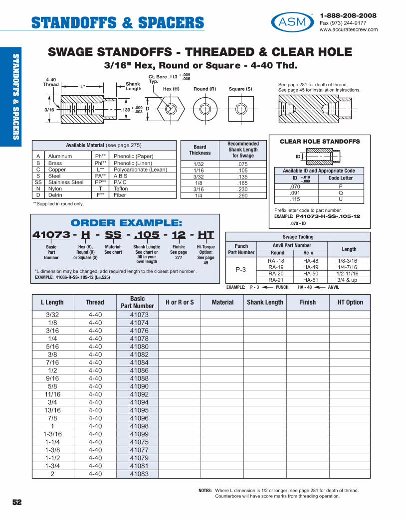
ST
AN
DO
FFS &
SPA
CE
RS
52
1-888-208-2008Fax (973) 244-9177www.accuratescrew.comSTANDOFFS & SPACERS
L Length Thread BasicPart Number H or R or S Material Shank Length Finish HT Option
3/32 4-40 410731/8 4-40 410743/16 4-40 410761/4 4-40 410785/16 4-40 410803/8 4-40 410827/16 4-40 410841/2 4-40 410869/16 4-40 410885/8 4-40 41090
11/16 4-40 410923/4 4-40 41094
13/16 4-40 410957/8 4-40 410961 4-40 41098
1-3/16 4-40 410991-1/4 4-40 410751-3/8 4-40 410771-1/2 4-40 410791-3/4 4-40 41081
2 4-40 41083
SWAGE STANDOFFS - THREADED & CLEAR HOLE3/16" Hex, Round or Square - 4-40 Thd.
NOTES: Where L dimension is 1/2 or longer, see page 281 for depth of thread.Counterbore will have score marks from threading operation.
EXAMPLE: P - 3 PUNCH HA - 48 ANVIL
RA -18 HA-48 1/8-3/16RA-19 HA-49 1/4-7/16RA-20 HA-50 1/2-11/16RA-21 HA-51 3/4 & up
Swage Tooling
P-3
Punch Part Number
Anvil Part NumberRound He x
Length
BoardThickness
RecommendedShank Length
for Swage
1/32 .0751/16 .1053/32 .1351/8 .1653/16 .2301/4 .290
A Aluminum Ph** Phenolic (Paper)B Brass Phl** Phenolic (Linen)C Copper L** Polycarbonate (Lexan)S Steel PA** A.B.S
SS Stainless Steel PP** P.V.CN Nylon T TeflonD Delrin F** Fiber
**Supplied in round only.
Available Material (see page 275)
See page 281 for depth of thread.See page 45 for installation instructions.
3/16 .139
Ct. Bore .113
+ .000– .003
+ .009– .005 4-40
Thread
ORDER EXAMPLE:41073
BasicPart
Number
HHex (H),
Round (R)or Square (S)
SSMaterial:See chart
.105Shank Length:See chart orfill in yourown length
12Finish:
See page277
----
*L dimension may be changed, add required length to the closest part number .EXAMPLE: 41086-R-SS-.105-12 (L=.525)
HTHi-Torque
Option:See page
45
-
CLEAR HOLE STANDOFFS
Available ID and Appropriate CodeID Code Letter
.070 P
.091 Q
.115 U
+.010–.000
Prefix letter code to part number.EXAMPLE: P41073-H-SS-.105-12
.070 - ID
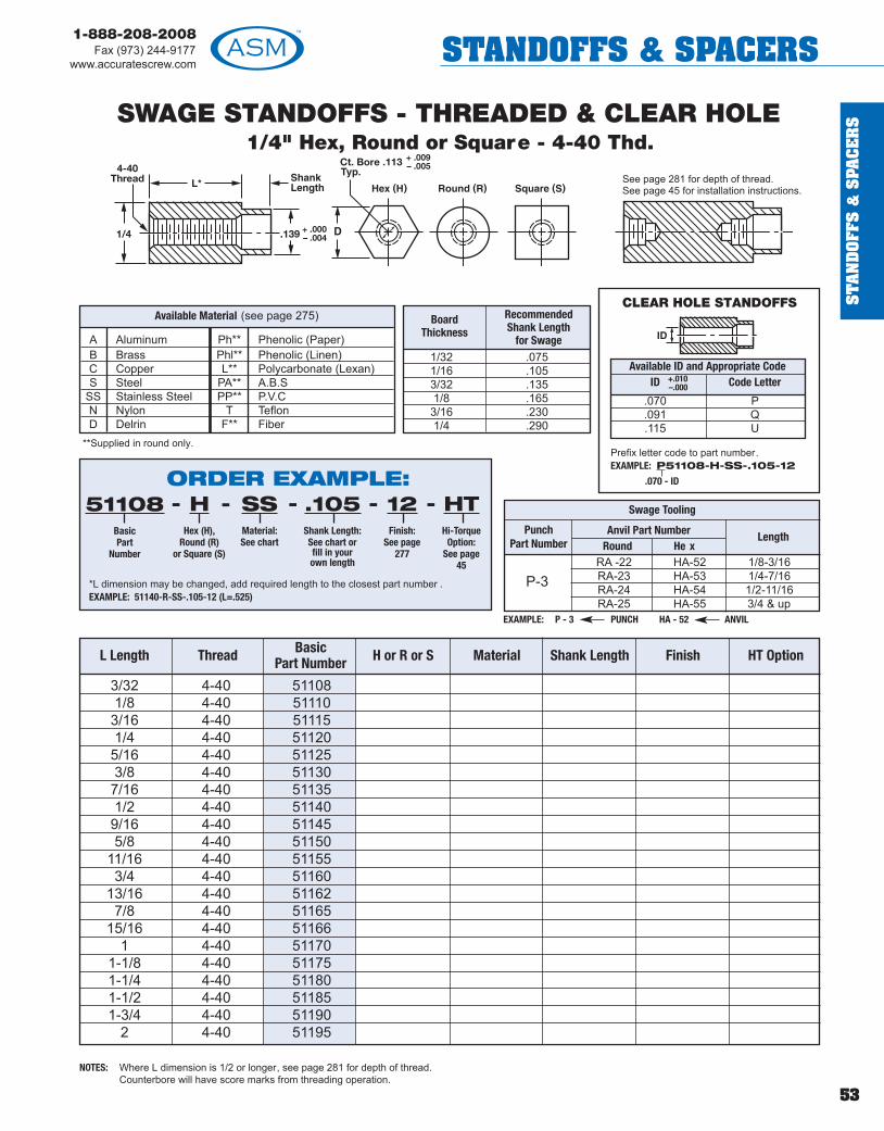
ST
AN
DO
FFS
&S
PAC
ER
S
53
1-888-208-2008Fax (973) 244-9177
www.accuratescrew.com STANDOFFS & SPACERS
L Length Thread BasicPart Number H or R or S Material Shank Length Finish HT Option
3/32 4-40 511081/8 4-40 511103/16 4-40 511151/4 4-40 511205/16 4-40 511253/8 4-40 511307/16 4-40 511351/2 4-40 511409/16 4-40 511455/8 4-40 51150
11/16 4-40 511553/4 4-40 51160
13/16 4-40 511627/8 4-40 51165
15/16 4-40 511661 4-40 51170
1-1/8 4-40 511751-1/4 4-40 511801-1/2 4-40 511851-3/4 4-40 51190
2 4-40 51195
SWAGE STANDOFFS - THREADED & CLEAR HOLE1/4" Hex, Round or Square - 4-40 Thd.
NOTES: Where L dimension is 1/2 or longer, see page 281 for depth of thread.Counterbore will have score marks from threading operation.
EXAMPLE: P - 3 PUNCH HA - 52 ANVIL
RA -22 HA-52 1/8-3/16RA-23 HA-53 1/4-7/16RA-24 HA-54 1/2-11/16RA-25 HA-55 3/4 & up
Swage Tooling
P-3
Punch Part Number
Anvil Part NumberRound He x
Length
BoardThickness
RecommendedShank Length
for Swage 1/32 .0751/16 .1053/32 .1351/8 .1653/16 .2301/4 .290
A Aluminum Ph** Phenolic (Paper)B Brass Phl** Phenolic (Linen)C Copper L** Polycarbonate (Lexan)S Steel PA** A.B.S
SS Stainless Steel PP** P.V.CN Nylon T TeflonD Delrin F** Fiber
**Supplied in round only.
Available Material (see page 275)
See page 281 for depth of thread.See page 45 for installation instructions.
1/4 .139
Ct. Bore .113
+ .000– .004
+ .009– .005 4-40
Thread
ORDER EXAMPLE:51108
BasicPart
Number
HHex (H),
Round (R)or Square (S)
SSMaterial:See chart
.105Shank Length:See chart orfill in yourown length
12Finish:
See page277
----
*L dimension may be changed, add required length to the closest part number .EXAMPLE: 51140-R-SS-.105-12 (L=.525)
HTHi-Torque
Option:See page
45
-
CLEAR HOLE STANDOFFS
Available ID and Appropriate CodeID Code Letter
.070 P
.091 Q
.115 U
+.010–.000
Prefix letter code to part number.EXAMPLE: P51108-H-SS-.105-12
.070 - ID

ST
AN
DO
FFS &
SPA
CE
RS
54
1-888-208-2008Fax (973) 244-9177www.accuratescrew.comSTANDOFFS & SPACERS
CLEAR HOLE STANDOFFS
L Length Thread BasicPart Number H or R or S Material Shank Length Finish HT Option
1/8 2-56 520103/16 2-56 520151/4 2-56 520205/16 2-56 520253/8 2-56 520307/16 2-56 520351/2 2-56 520409/16 2-56 520455/8 2-56 52050
11/16 2-56 520553/4 2-56 52060
13/16 2-56 520627/8 2-56 52065
15/16 2-56 520661 2-56 52070
1-1/8 2-56 520751-1/4 2-56 520801-1/2 2-56 520851-3/4 2-56 52090
2 2-56 52095
SWAGE STANDOFFS - THREADED & CLEAR HOLE1/4" Hex, Round or Square - 2-56 Thd.
NOTE: Where L dimension is 1/2 or longer, see page 281 for depth of thread.
Available ID and Appropriate CodeID Code Letter ID Code Letter
.070 P .140 W
.091 Q .150 WW
.115 U .156 XX
.120 V
EXAMPLE: P - 4 PUNCH HA - 52 ANVIL
RA -22 HA-52 1/8-3/16RA-23 HA-53 1/4-7/16RA-24 HA-54 1/2-11/16RA-25 HA-55 3/4 & up
Swage Tooling
P-4
Punch Part Number
Anvil Part NumberRound He x
Length
+.010–.000
+.010–.000
BoardThickness
RecommendedShank Length
for Swage
1/32 .0751/16 .1053/32 .1351/8 .1653/16 .2301/4 .290
A Aluminum Ph** Phenolic (Paper)B Brass Phl** Phenolic (Linen)C Copper L** Polycarbonate (Lexan)S Steel PA** A.B.S
SS Stainless Steel PP** P.V.CN Nylon T TeflonD Delrin F** Fiber
**Supplied in round only.
Available Material (see page 275)
See page 281 for depth of thread.See page 45 for installation instructions.
1/4 .188
Ct. Bore .150
+ .000– .003
+ .002– .001 2-56
Thread
ORDER EXAMPLE:52010
BasicPart
Number
HHex (H),
Round (R)or Square (S)
SSMaterial:See chart
.105Shank Length:See chart orfill in yourown length
12Finish:
See page277
----
*L dimension may be changed, add required length to the closest part number .EXAMPLE: 52040-R-SS-.105-12 (L=.525)
HTHi-Torque
Option:See page
45
-
Prefix letter code to part number.EXAMPLE: P52010-H-SS-.105-12
.070 - ID

ST
AN
DO
FFS
&S
PAC
ER
S
55
1-888-208-2008Fax (973) 244-9177
www.accuratescrew.com STANDOFFS & SPACERS
L Length Thread BasicPart Number H or R or S Material Shank Length Finish HT Option
1/8 3-48 540103/16 3-48 540121/4 3-48 540145/16 3-48 540163/8 3-48 540187/16 3-48 540201/2 3-48 540229/16 3-48 540245/8 3-48 54026
11/16 3-48 540283/4 3-48 54030
13/16 3-48 540327/8 3-48 54034
15/16 3-48 540361 3-48 54038
1-1/8 3-48 540401-1/4 3-48 540421-1/2 3-48 540441-3/4 3-48 54046
2 3-48 54048
SWAGE STANDOFFS - THREADED & CLEAR HOLE1/4" Hex, Round or Square - 3-48 Thd.
NOTE: Where L dimension is 1/2 or longer, see page 281 for depth of thread.
EXAMPLE: P - 4 PUNCH HA - 52 ANVIL
RA -22 HA-52 1/8-3/16RA-23 HA-53 1/4-7/16RA-24 HA-54 1/2-11/16RA-25 HA-55 3/4 & up
Swage Tooling
P-4
Punch Part Number
Anvil Part NumberRound He x
Length
See page 281 for depth of thread.See page 45 for installation instructions.
1/4 .188
Ct. Bore .150
+ .000– .003
+ .002– .001 3-48
Thread
ORDER EXAMPLE:54010
BasicPart
Number
HHex (H),
Round (R)or Square (S)
SSMaterial:See chart
.105Shank Length:See chart orfill in yourown length
12Finish:
See page277
----
*L dimension may be changed, add required length to the closest part number .EXAMPLE: 54022-R-SS-.105-12 (L=.525)
HTHi-Torque
Option:See page
45
-
CLEAR HOLE STANDOFFS
Available ID and Appropriate CodeID Code Letter ID Code Letter
.070 P .140 W
.091 Q .150 WW
.115 U .156 XX
.120 V
+.010–.000
+.010–.000
Prefix letter code to part number.EXAMPLE: Q54010-H-SS-.105-12
.091 - ID
BoardThickness
RecommendedShank Length
for Swage
1/32 .0751/16 .1053/32 .1351/8 .1653/16 .2301/4 .290
A Aluminum Ph** Phenolic (Paper)B Brass Phl** Phenolic (Linen)C Copper L** Polycarbonate (Lexan)S Steel PA** A.B.S
SS Stainless Steel PP** P.V.CN Nylon T TeflonD Delrin F** Fiber
**Supplied in round only.
Available Material (see page 275)

ST
AN
DO
FFS &
SPA
CE
RS
56
1-888-208-2008Fax (973) 244-9177www.accuratescrew.comSTANDOFFS & SPACERS
L Length Thread BasicPart Number H or R or S Material Shank Length Finish HT Option
1/8 4-40 510103/16 4-40 510151/4 4-40 510205/16 4-40 510253/8 4-40 510307/16 4-40 510351/2 4-40 510409/16 4-40 510455/8 4-40 51050
11/16 4-40 510553/4 4-40 51060
13/16 4-40 510627/8 4-40 51065
15/16 4-40 510661 4-40 51070
1-1/8 4-40 510751-1/4 4-40 510801-1/2 4-40 510851-3/4 4-40 51090
2 4-40 51095
SWAGE STANDOFFS - THREADED & CLEAR HOLE1/4" Hex, Round or Square - 4-40 Thd.
NOTE: Where L dimension is 1/2 or longer, see page 281 for depth of thread.
EXAMPLE: P - 4 PUNCH HA - 52 ANVIL
RA -22 HA-52 1/8-3/16RA-23 HA-53 1/4-7/16RA-24 HA-54 1/2-11/16RA-25 HA-55 3/4 & up
Swage Tooling
P-4
Punch Part Number
Anvil Part NumberRound He x
Length
BoardThickness
RecommendedShank Length
for Swage
1/32 .0751/16 .1053/32 .1351/8 .1653/16 .2301/4 .290
A Aluminum Ph** Phenolic (Paper)B Brass Phl** Phenolic (Linen)C Copper L** Polycarbonate (Lexan)S Steel PA** A.B.S
SS Stainless Steel PP** P.V.CN Nylon T TeflonD Delrin F** F ber
**Supplied in round only.
Available Material (see page 275)
See page 281 for depth of thread.See page 45 for installation instructions.
1/4 .188
Ct. Bore .150
+ .000– .003
+ .002– .001 4-40
Thread
ORDER EXAMPLE:51010
BasicPart
Number
HHex (H),
Round (R)or Square (S)
SSMaterial:See chart
.105Shank Length:See chart orfill in yourown length
12Finish:
See page277
----
*L dimension may be changed, add required length to the closest part number .EXAMPLE: 51040-R-SS-.105-12 (L=.525)
HTHi-Torque
Option:See page
45
-
CLEAR HOLE STANDOFFS
Available ID and Appropriate CodeID Code Letter ID Code Letter
.070 P .140 W
.091 Q .150 WW
.115 U .156 XX
.120 V
+.010–.000
+.010–.000
Prefix letter code to part number.EXAMPLE: P51010-H-SS-.105-12
.070 - ID

ST
AN
DO
FFS
&S
PAC
ER
S
57
1-888-208-2008Fax (973) 244-9177
www.accuratescrew.com STANDOFFS & SPACERS
L Length Thread BasicPart Number H or R or S Material Shank Length Finish HT Option
1/8 6-32 610103/16 6-32 610157/32 6-32 610171/4 6-32 610209/32 6-32 610225/16 6-32 6102511/32 6-32 610273/8 6-32 610307/16 6-32 610351/2 6-32 610409/16 6-32 610455/8 6-32 61050
11/16 6-32 610553/4 6-32 61060
13/16 6-32 610627/8 6-32 61065
15/16 6-32 610671 6-32 61070
1-1/8 6-32 610751-1/4 6-32 610801-3/8 6-32 610811-1/2 6-32 610851-3/4 6-32 61087
2 6-32 61089
SWAGE STANDOFFS - THREADED & CLEAR HOLE1/4" Hex, Round or Square - 6-32 Thd.
NOTE: Where L dimension is 1/2 or longer, see page 281 for depth of thread.
EXAMPLE: P - 4 PUNCH HA - 52 ANVIL
RA -22 HA-52 1/8-3/16RA-23 HA-53 1/4-7/16RA-24 HA-54 1/2-11/16RA-25 HA-55 3/4 & up
Swage Tooling
P-4
Punch Part Number
Anvil Part NumberRound He x
Length
BoardThickness
RecommendedShank Length
for Swage
1/32 .0751/16 .1053/32 .1351/8 .1653/16 .2301/4 .290
A Aluminum Ph** Phenolic (Paper)B Brass Phl** Phenolic (Linen)C Copper L** Polycarbonate (Lexan)S Steel PA** A.B.S
SS Stainless Steel PP** P.V.CN Nylon T TeflonD Delrin F** Fiber
**Supplied in round only.
Available Material (see page 275)
See page 281 for depth of thread.See page 45 for installation instructions.
1/4 .188
Ct. Bore .150
+ .000– .003
+ .003– .001 6-32
Thread
ORDER EXAMPLE:61010
BasicPart
Number
HHex (H),
Round (R)or Square (S)
SSMaterial:See chart
.105Shank Length:See chart orfill in yourown length
12Finish:
See page277
----
*L dimension may be changed, add required length to the closest part number .EXAMPLE: 61040-R-SS-.105-12 (L=.525)
HTHi-Torque
Option:See page
45
-
CLEAR HOLE STANDOFFS
Available ID and Appropriate CodeID Code Letter ID Code Letter
.091 Q .140 W
.115 U .150 WW
.120 V .156 XX
+.010–.000
+.010–.000
Prefix letter code to part number.EXAMPLE: Q61010-H-SS-.105-12
.091 - ID

ST
AN
DO
FFS &
SPA
CE
RS
58
1-888-208-2008Fax (973) 244-9177www.accuratescrew.comSTANDOFFS & SPACERS
L Length Thread BasicPart Number H or R or S Material Shank Length Finish HT Option
1/8 8-32 622003/16 8-32 622027/32 8-32 622041/4 8-32 622069/32 8-32 622085/16 8-32 6221011/32 8-32 622123/8 8-32 622147/16 8-32 622161/2 8-32 622189/16 8-32 622205/8 8-32 62222
11/16 8-32 622243/4 8-32 62226
13/16 8-32 622287/8 8-32 62230
15/16 8-32 622321 8-32 62234
1-1/8 8-32 622361-1/4 8-32 622381-3/8 8-32 622401-1/2 8-32 622421-3/4 8-32 62244
2 8-32 62246
SWAGE STANDOFFS - THREADED & CLEAR HOLE1/4" Hex, Round or Square - 8-32 Thd.
NOTE: Where L dimension is 1/2 or longer, see page 281 for depth of thread.
BoardThickness
RecommendedShank Length
for Swage
1/32 .0751/16 .1053/32 .1351/8 .1653/16 .2301/4 .290
A Aluminum Ph** Phenolic (Paper)B Brass Phl** Phenolic (Linen)C Copper L** Polycarbonate (Lexan)S Steel PA** A.B.S
SS Stainless Steel PP** P.V.CN Nylon T TeflonD Delrin F** F ber
**Supplied in round only.
Available Material (see page 275)
See page 281 for depth of thread.See page 45 for installation instructions.
1/4 .215
Ct. Bore .175
+ .000– .003
+ .002– .001 8-32
Thread
STAKING TOOLSARE NOT AVAILABLE
FOR THIS PART NUMBER
ORDER EXAMPLE:62200
BasicPart
Number
HHex (H),
Round (R)or Square (S)
SSMaterial:See chart
.105Shank Length:See chart orfill in yourown length
12Finish:
See page277
----
*L dimension may be changed, add required length to the closest part number .EXAMPLE: 62218-R-SS-.105-12 (L=.525)
HTHi-Torque
Option:See page
45
-
CLEAR HOLE STANDOFFS
Available ID and Appropriate CodeID Code Letter ID Code Letter
.091 Q .150 WW
.115 U .156 XX
.120 V .171 X
.140 W
+.010–.000
+.010–.000
Prefix letter code to part number.EXAMPLE: Q62200-H-SS-.105-12
.091 - ID

ST
AN
DO
FFS
&S
PAC
ER
S
59
1-888-208-2008Fax (973) 244-9177
www.accuratescrew.com STANDOFFS & SPACERS
L Length Thread BasicPart Number H or R or S Material Shank Length Finish HT Option
1/8 6-32 710103/16 6-32 710151/4 6-32 710205/16 6-32 710253/8 6-32 710307/16 6-32 710351/2 6-32 710409/16 6-32 710455/8 6-32 71050
11/16 6-32 710553/4 6-32 71060
13/16 6-32 710627/8 6-32 71065
15/16 6-32 710671 6-32 71070
1-1/8 6-32 710751-1/4 6-32 710801-1/2 6-32 710851-3/4 6-32 71090
2 6-32 71095
SWAGE STANDOFFS - THREADED & CLEAR HOLE5/16" Hex, Round or Square - 6-32 Thd.
NOTE: Where L dimension is 1/2 or longer, see page 281 for depth of thread.
EXAMPLE: P - 5 PUNCH HA - 56 ANVIL
RA -26 HA-56 1/8-3/16RA-27 HA-57 1/4-7/16RA-28 HA-58 1/2-11/16RA-29 HA-59 3/4 & up
Swage Tooling
P-5
Punch Part Number
Anvil Part NumberRound He x
Length
BoardThickness
RecommendedShank Length
for Swage
1/32 .0751/16 .1053/32 .1351/8 .1653/16 .2301/4 .290
A Aluminum Ph** Phenolic (Paper)B Brass Phl** Phenolic (Linen)C Copper L** Polycarbonate (Lexan)S Steel PA** A.B.S
SS Stainless Steel PP** P.V.CN Nylon T TeflonD Delrin F** Fiber
**Supplied in round only.
Available Material (see page 275)
See page 281 for depth of thread.See page 45 for installation instructions.
5/16 .234
Ct. Bore .201
+ .000– .003
+ .002– .001 6-32
Thread
ORDER EXAMPLE:71010
BasicPart
Number
HHex (H),
Round (R)or Square (S)
SSMaterial:See chart
.105Shank Length:See chart orfill in yourown length
12Finish:
See page277
----
*L dimension may be changed, add required length to the closest part number .EXAMPLE: 71040-R-SS-.105-12 (L=.525)
HTHi-Torque
Option:See page
45
-
CLEAR HOLE STANDOFFS
Available ID and Appropriate CodeID Code Letter ID Code Letter
.091 Q .150 WW
.115 U .156 XX
.120 V .171 X
.140 W .194 Y
+.010–.000
+.010–.000
Prefix letter code to part number.EXAMPLE: W71010-H-SS-.105-12
.140 - ID
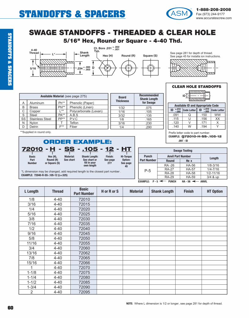
ST
AN
DO
FFS &
SPA
CE
RS
60
1-888-208-2008Fax (973) 244-9177www.accuratescrew.comSTANDOFFS & SPACERS
L Length Thread BasicPart Number H or R or S Material Shank Length Finish HT Option
1/8 4-40 720103/16 4-40 720151/4 4-40 720205/16 4-40 720253/8 4-40 720307/16 4-40 720351/2 4-40 720409/16 4-40 720455/8 4-40 72050
11/16 4-40 720553/4 4-40 72060
13/16 4-40 720627/8 4-40 72065
15/16 4-40 720661 4-40 72070
1-1/8 4-40 720751-1/4 4-40 720801-1/2 4-40 720851-3/4 4-40 72090
2 4-40 72095
SWAGE STANDOFFS - THREADED & CLEAR HOLE5/16" Hex, Round or Square - 4-40 Thd.
NOTE: Where L dimension is 1/2 or longer, see page 281 for depth of thread.
EXAMPLE: P - 5 PUNCH HA - 56 ANVIL
RA -26 HA-56 1/8-3/16RA-27 HA-57 1/4-7/16RA-28 HA-58 1/2-11/16RA-29 HA-59 3/4 & up
Swage Tooling
P-5
Punch Part Number
Anvil Part NumberRound He x
Length
BoardThickness
RecommendedShank Length
for Swage
1/32 .0751/16 .1053/32 .1351/8 .1653/16 .2301/4 .290
A Aluminum Ph** Phenolic (Paper)B Brass Phl** Phenolic (Linen)C Copper L** Polycarbonate (Lexan)S Steel PA** A.B.S
SS Stainless Steel PP** P.V.CN Nylon T TeflonD Delrin F** Fiber
**Supplied in round only.
Available Material (see page 275)
See page 281 for depth of thread.See page 45 for installa ion instructions.
5/16 .234
Ct. Bore .201
+ .000– .003
+ .002– .001 4-40
Thread
ORDER EXAMPLE:72010
BasicPart
Number
HHex (H),
Round (R)or Square (S)
SSMaterial:See chart
.105Shank Length:See chart orfill in yourown length
12Finish:
See page277
----
*L dimension may be changed, add required length to the closest part number .EXAMPLE: 72040-R-SS-.105-12 (L=.525)
HTHi-Torque
Option:See page
45
-
CLEAR HOLE STANDOFFS
Available ID and Appropriate CodeID Code Letter ID Code Letter
.091 Q .150 WW
.115 U .156 XX
.120 V .171 X
.140 W .194 Y
+.010–.000
+.010–.000
Prefix letter code to part number.EXAMPLE: Q72010-H-SS-.105-12
.091 - ID
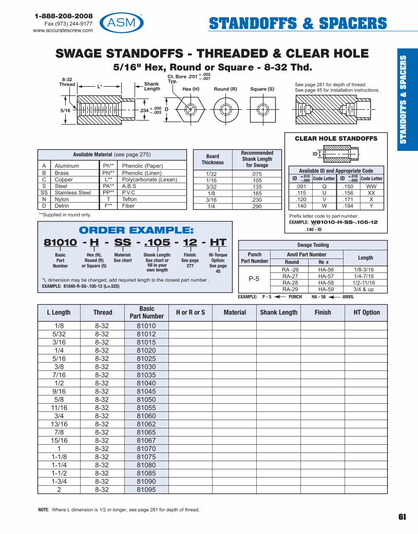
ST
AN
DO
FFS
&S
PAC
ER
S
61
1-888-208-2008Fax (973) 244-9177
www.accuratescrew.com STANDOFFS & SPACERS
L Length Thread BasicPart Number H or R or S Material Shank Length Finish HT Option
1/8 8-32 810105/32 8-32 810123/16 8-32 810151/4 8-32 810205/16 8-32 810253/8 8-32 810307/16 8-32 810351/2 8-32 810409/16 8-32 810455/8 8-32 81050
11/16 8-32 810553/4 8-32 81060
13/16 8-32 810627/8 8-32 81065
15/16 8-32 810671 8-32 81070
1-1/8 8-32 810751-1/4 8-32 810801-1/2 8-32 810851-3/4 8-32 81090
2 8-32 81095
SWAGE STANDOFFS - THREADED & CLEAR HOLE5/16" Hex, Round or Square - 8-32 Thd.
NOTE: Where L dimension is 1/2 or longer, see page 281 for depth of thread.
EXAMPLE: P - 5 PUNCH HA - 56 ANVIL
RA -26 HA-56 1/8-3/16RA-27 HA-57 1/4-7/16RA-28 HA-58 1/2-11/16RA-29 HA-59 3/4 & up
Swage Tooling
P-5
Punch Part Number
Anvil Part NumberRound He x
Length
BoardThickness
RecommendedShank Length
for Swage
1/32 .0751/16 .1053/32 .1351/8 .1653/16 .2301/4 .290
A Aluminum Ph** Phenolic (Paper)B Brass Phl** Phenolic (Linen)C Copper L** Polycarbonate (Lexan)S Steel PA** A.B.S
SS Stainless Steel PP** P.V.CN Nylon T TeflonD Delrin F** Fiber
**Supplied in round only.
Available Material (see page 275)
See page 281 for depth of thread.See page 45 for installation instructions.
5/16 .234
Ct. Bore .201
+ .000– .003
+ .002– .001 8-32
Thread
ORDER EXAMPLE:81010
BasicPart
Number
HHex (H),
Round (R)or Square (S)
SSMaterial:See chart
.105Shank Length:See chart orfill in yourown length
12Finish:
See page277
----
*L dimension may be changed, add required length to the closest part number .EXAMPLE: 81040-R-SS-.105-12 (L=.525)
HTHi-Torque
Option:See page
45
-
CLEAR HOLE STANDOFFS
Available ID and Appropriate CodeID Code Letter ID Code Letter
.091 Q .150 WW
.115 U .156 XX
.120 V .171 X
.140 W .194 Y
+.010–.000
+.010–.000
Prefix letter code to part number.EXAMPLE: W81010-H-SS-.105-12
.140 - ID

ST
AN
DO
FFS &
SPA
CE
RS
62
1-888-208-2008Fax (973) 244-9177www.accuratescrew.comSTANDOFFS & SPACERS
L Length Thread BasicPart Number H or R or S Material Shank Length Finish HT Option
1/8 10-32 820105/32 10-32 820123/16 10-32 820141/4 10-32 820165/16 10-32 820183/8 10-32 820207/16 10-32 820221/2 10-32 820249/16 10-32 820265/8 10-32 82028
11/16 10-32 820303/4 10-32 82032
13/16 10-32 820347/8 10-32 820361 10-32 82038
1-1/8 10-32 820401-1/4 10-32 820421-1/2 10-32 820441-3/4 10-32 82046
2 10-32 82048
SWAGE STANDOFFS - THREADED & CLEAR HOLE5/16" Hex, Round or Square - 10-32 Thd.
NOTE: Where L dimension is 1/2 or longer, see page 281 for depth of thread.
EXAMPLE: P - 5 PUNCH HA - 56 ANVIL
RA -26 HA-56 1/8-3/16RA-27 HA-57 1/4-7/16RA-28 HA-58 1/2-11/16RA-29 HA-59 3/4 & up
Swage Tooling
P-5
Punch Part Number
Anvil Part NumberRound He x
Length
BoardThickness
RecommendedShank Length
for Swage
1/32 .0751/16 .1053/32 .1351/8 .1653/16 .2301/4 .290
A Aluminum Ph** Phenolic (Paper)B Brass Phl** Phenolic (Linen)C Copper L** Polycarbonate (Lexan)S Steel PA** A.B.S
SS Stainless Steel PP** P.V.CN Nylon T TeflonD Delrin F** F ber
**Supplied in round only.
Available Material (see page 275)
See page 281 for depth of thread.See page 45 for installation instructions.
5/16 .234
Ct. Bore .201
+ .000– .003
+ .002– .001 10-32
Thread
ORDER EXAMPLE:82010
BasicPart
Number
HHex (H),
Round (R)or Square (S)
SSMaterial:See chart
.105Shank Length:See chart orfill in yourown length
12Finish:
See page277
----
*L dimension may be changed, add required length to the closest part number .EXAMPLE: 82024-R-SS-.105-12 (L=.525)
HTHi-Torque
Option:See page
45
-
CLEAR HOLE STANDOFFS
Available ID and Appropriate CodeID Code Letter ID Code Letter
.091 Q .150 WW
.115 U .156 XX
.120 V .171 X
.140 W .194 Y
+.010–.000
+.010–.000
Prefix letter code to part number.EXAMPLE: Q82010-H-SS-.105-12
.091 - ID

ST
AN
DO
FFS
&S
PAC
ER
S
63
1-888-208-2008Fax (973) 244-9177
www.accuratescrew.com STANDOFFS & SPACERS
L Length Thread BasicPart Number H or R or S Material Shank Length Finish HT Option
1/8 3-48 530103/16 3-48 530151/4 3-48 530205/16 3-48 530253/8 3-48 530307/16 3-48 530351/2 3-48 530409/16 3-48 530455/8 3-48 53050
11/16 3-48 530553/4 3-48 53060
13/16 3-48 530627/8 3-48 53065
15/16 3-48 530661 3-48 53070
1-1/8 3-48 530751-1/4 3-48 530801-1/2 3-48 530851-3/4 3-48 53090
2 3-48 53095
SWAGE STANDOFFS - THREADED & CLEAR HOLE3/8" Hex, Round or Square - 3/48 Thd.
NOTE: Where L dimension is 1/2 or longer, see page 281 for depth of thread.
EXAMPLE: P - 5 PUNCH HA - 60 ANVIL
RA -30 HA-60 1/8-3/16RA-31 HA-61 1/4-7/16RA-32 HA-62 1/2-11/16RA-33 HA-63 3/4 & up
Swage Tooling
P-5
Punch Part Number
Anvil Part NumberRound He x
Length
BoardThickness
RecommendedShank Length
for Swage
1/32 .0751/16 .1053/32 .1351/8 .1653/16 .2301/4 .290
A Aluminum Ph** Phenolic (Paper)B Brass Phl** Phenolic (Linen)C Copper L** Polycarbonate (Lexan)S Steel PA** A.B.S
SS Stainless Steel PP** P.V.CN Nylon T TeflonD Delrin F** F ber
**Supplied in round only.
Available Material (see page 275)
See page 281 for depth of thread.See page 45 for installation instructions.
3/8 .234
Ct. Bore .201
+ .000– .003
+ .002– .001 3-48
Thread
ORDER EXAMPLE:53010
BasicPart
Number
HHex (H),
Round (R)or Square (S)
SSMaterial:See chart
.105Shank Length:See chart orfill in yourown length
12Finish:
See page277
----
*L dimension may be changed, add required length to the closest part number .EXAMPLE: 53040-R-SS-.105-12 (L=.525)
HTHi-Torque
Option:See page
45
-
CLEAR HOLE STANDOFFS
Available ID and Appropriate CodeID Code Letter ID Code Letter
.091 Q .150 WW
.115 U .156 XX
.120 V .171 X
.140 W .194 Y
+.010–.000
+.010–.000
Prefix letter code to part number.EXAMPLE: W53010-H-SS-.105-12
.140 - ID
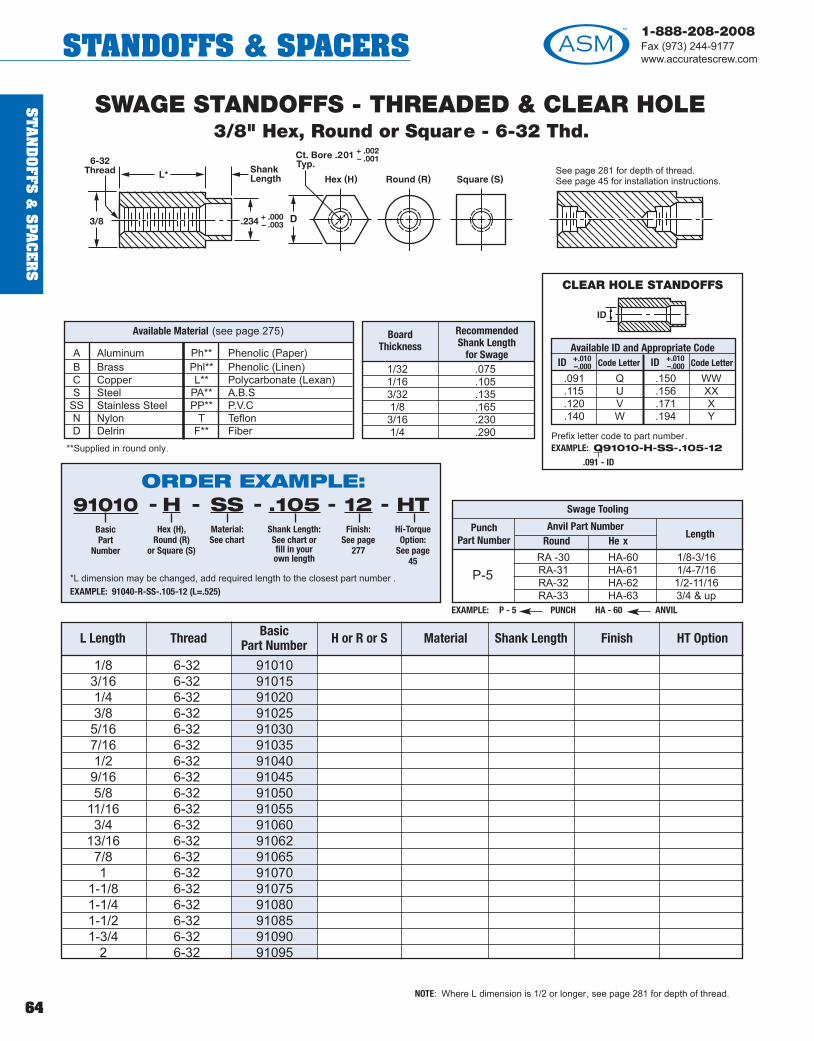
ST
AN
DO
FFS &
SPA
CE
RS
64
1-888-208-2008Fax (973) 244-9177www.accuratescrew.comSTANDOFFS & SPACERS
L Length Thread BasicPart Number H or R or S Material Shank Length Finish HT Option
1/8 6-32 910103/16 6-32 910151/4 6-32 910203/8 6-32 910255/16 6-32 910307/16 6-32 910351/2 6-32 910409/16 6-32 910455/8 6-32 91050
11/16 6-32 910553/4 6-32 91060
13/16 6-32 910627/8 6-32 910651 6-32 91070
1-1/8 6-32 910751-1/4 6-32 910801-1/2 6-32 910851-3/4 6-32 91090
2 6-32 91095
SWAGE STANDOFFS - THREADED & CLEAR HOLE3/8" Hex, Round or Square - 6-32 Thd.
NOTE: Where L dimension is 1/2 or longer, see page 281 for depth of thread.
EXAMPLE: P - 5 PUNCH HA - 60 ANVIL
RA -30 HA-60 1/8-3/16RA-31 HA-61 1/4-7/16RA-32 HA-62 1/2-11/16RA-33 HA-63 3/4 & up
Swage Tooling
P-5
Punch Part Number
Anvil Part NumberRound He x
Length
BoardThickness
RecommendedShank Length
for Swage 1/32 .0751/16 .1053/32 .1351/8 .1653/16 .2301/4 .290
A Aluminum Ph** Phenolic (Paper)B Brass Phl** Phenolic (Linen)C Copper L** Polycarbonate (Lexan)S Steel PA** A.B.S
SS Stainless Steel PP** P.V.CN Nylon T TeflonD Delrin F** Fiber
**Supplied in round only.
Available Material (see page 275)
See page 281 for depth of thread.See page 45 for installation instructions.
3/8 .234
Ct. Bore .201
+ .000– .003
+ .002– .001 6-32
Thread
ORDER EXAMPLE:91010
BasicPart
Number
HHex (H),
Round (R)or Square (S)
SSMaterial:See chart
.105Shank Length:See chart orfill in yourown length
12Finish:
See page277
----
*L dimension may be changed, add required length to the closest part number .EXAMPLE: 91040-R-SS-.105-12 (L=.525)
HTHi-Torque
Option:See page
45
-
CLEAR HOLE STANDOFFS
Available ID and Appropriate CodeID Code Letter ID Code Letter
.091 Q .150 WW
.115 U .156 XX
.120 V .171 X
.140 W .194 Y
+.010–.000
+.010–.000
Prefix letter code to part number.EXAMPLE: Q91010-H-SS-.105-12
.091 - ID
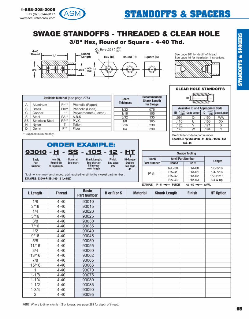
ST
AN
DO
FFS
&S
PAC
ER
S
65
1-888-208-2008Fax (973) 244-9177
www.accuratescrew.com STANDOFFS & SPACERS
L Length Thread BasicPart Number H or R or S Material Shank Length Finish HT Option
1/8 4-40 930103/16 4-40 930151/4 4-40 930205/16 4-40 930253/8 4-40 930307/16 4-40 930351/2 4-40 930409/16 4-40 930455/8 4-40 93050
11/16 4-40 930553/4 4-40 93060
13/16 4-40 930627/8 4-40 93065
15/16 4-40 930661 4-40 93070
1-1/8 4-40 930751-1/4 4-40 930801-1/2 4-40 930851-3/4 4-40 93090
2 4-40 93095
SWAGE STANDOFFS - THREADED & CLEAR HOLE3/8" Hex, Round or Square - 4-40 Thd.
NOTE: Where L dimension is 1/2 or longer, see page 281 for depth of thread.
EXAMPLE: P - 5 PUNCH HA - 60 ANVIL
RA -30 HA-60 1/8-3/16RA-31 HA-61 1/4-7/16RA-32 HA-62 1/2-11/16RA-33 HA-63 3/4 & up
Swage Tooling
P-5
Punch Part Number
Anvil Part NumberRound He x
Length
BoardThickness
RecommendedShank Length
for Swage
1/32 .0751/16 .1053/32 .1351/8 .1653/16 .2301/4 .290
A Aluminum Ph** Phenolic (Paper)B Brass Phl** Phenolic (Linen)C Copper L** Polycarbonate (Lexan)S Steel PA** A.B.S
SS Stainless Steel PP** P.V.CN Nylon T TeflonD Delrin F** Fiber
**Supplied in round only.
Available Material (see page 275)
See page 281 for depth of thread.See page 45 for installation instructions.
3/8 .234
Ct. Bore .201
+ .000– .003
+ .002– .001 4-40
Thread
CLEAR HOLE STANDOFFS
Available ID and Appropriate CodeID Code Letter ID Code Letter
.091 Q .150 WW
.115 U .156 XX
.120 V .171 X
.140 W .194 Y
+.010–.000
+.010–.000
Prefix letter code to part number.EXAMPLE: W93010-H-SS-.105-12
.140 - IDORDER EXAMPLE:93010
BasicPart
Number
HHex (H),
Round (R)or Square (S)
SSMaterial:See chart
.105Shank Length:See chart orfill in yourown length
12Finish:
See page277
----
*L dimension may be changed, add required length to the closest part number .EXAMPLE: 93040-R-SS-.105-12 (L=.525)
HTHi-Torque
Option:See page
45
-

ST
AN
DO
FFS &
SPA
CE
RS
66
1-888-208-2008Fax (973) 244-9177www.accuratescrew.comSTANDOFFS & SPACERS
L Length Thread BasicPart Number H or R or S Material Shank Length Finish HT Option
1/8 8-32 120103/16 8-32 120151/4 8-32 120205/16 8-32 120253/8 8-32 120307/16 8-32 120351/2 8-32 120409/16 8-32 120455/8 8-32 12050
11/16 8-32 120553/4 8-32 12060
13/16 8-32 120627/8 8-32 120651 8-32 12070
1-1/8 8-32 120751-1/4 8-32 120801-1/2 8-32 120851-3/4 8-32 12090
2 8-32 12095
SWAGE STANDOFFS - THREADED & CLEAR HOLE3/8" Hex, Round or Square - 8-32 Thd.
NOTE: Where L dimension is 1/2 or longer, see page 281 for depth of thread.
EXAMPLE: P - 5 PUNCH HA - 60 ANVIL
RA -30 HA-60 1/8-3/16RA-31 HA-61 1/4-7/16RA-32 HA-62 1/2-11/16RA-33 HA-63 3/4 & up
Swage Tooling
P-5
Punch Part Number
Anvil Part NumberRound He x
Length
BoardThickness
RecommendedShank Length
for Swage
1/32 .0751/16 .1053/32 .1351/8 .1653/16 .2301/4 .290
A Aluminum Ph** Phenolic (Paper)B Brass Phl** Phenolic (Linen)C Copper L** Polycarbonate (Lexan)S Steel PA** A.B.S
SS Stainless Steel PP** P.V.CN Nylon T TeflonD Delrin F** Fiber
**Supplied in round only.
Available Material (see page 275)
See page 281 for depth of thread.See page 45 for installation instructions.
3/8 .234
Ct. Bore .201
+ .000– .003
+ .002– .001 8-32
Thread
CLEAR HOLE STANDOFFS
Available ID and Appropriate CodeID Code Letter ID Code Letter
.091 Q .150 WW
.115 U .156 XX
.120 V .171 X
.140 W .194 Y
+.010–.000
+.010–.000
Prefix letter code to part number.EXAMPLE: Q12010-H-SS-.105-12
.091 - IDORDER EXAMPLE:12010
BasicPart
Number
HHex (H),
Round (R)or Square (S)
SSMaterial:See chart
.105Shank Length:See chart orfill in yourown length
12Finish:
See page277
----
*L dimension may be changed, add required length to the closest part number .EXAMPLE: 12040-R-SS-.105-12 (L=.525)
HTHi-Torque
Option:See page
45
-
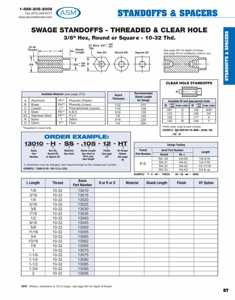
ST
AN
DO
FFS
&S
PAC
ER
S
67
1-888-208-2008Fax (973) 244-9177
www.accuratescrew.com STANDOFFS & SPACERS
L Length Thread BasicPart Number H or R or S Material Shank Length Finish HT Option
1/8 10-32 130103/16 10-32 130151/4 10-32 130205/16 10-32 130253/8 10-32 130307/16 10-32 130351/2 10-32 130409/16 10-32 130455/8 10-32 13050
11/16 10-32 130553/4 10-32 13060
13/16 10-32 130627/8 10-32 130651 10-32 13070
1-1/8 10-32 130751-1/4 10-32 130801-1/2 10-32 130851-3/4 10-32 13090
2 10-32 13095
SWAGE STANDOFFS - THREADED & CLEAR HOLE3/8" Hex, Round or Square - 10-32 Thd.
NOTE: Where L dimension is 1/2 or longer, see page 281 for depth of thread.
EXAMPLE: P - 5 PUNCH HA - 60 ANVIL
RA -30 HA-60 1/8-3/16RA-31 HA-61 1/4-7/16RA-32 HA-62 1/2-11/16RA-33 HA-63 3/4 & up
Swage Tooling
P-5
Punch Part Number
Anvil Part NumberRound He x
Length
BoardThickness
RecommendedShank Length
for Swage
1/32 .0751/16 .1053/32 .1351/8 .1653/16 .2301/4 .290
A Aluminum Ph** Phenolic (Paper)B Brass Phl** Phenolic (Linen)C Copper L** Polycarbonate (Lexan)S Steel PA** A.B.S
SS Stainless Steel PP** P.V.CN Nylon T TeflonD Delrin F** Fiber
**Supplied in round only.
Available Material (see page 275)
See page 281 for depth of thread.See page 45 for installation instruc ions.
3/8 .234
Ct. Bore .201
+ .000– .003
+ .002– .001 10-32
Thread
CLEAR HOLE STANDOFFS
Available ID and Appropriate CodeID Code Letter ID Code Letter
.091 Q .150 WW
.115 U .156 XX
.120 V .171 X
.140 W .194 Y
+.010–.000
+.010–.000
Prefix letter code to part number.EXAMPLE: W13010-H-SS-.105-12
.140 - IDORDER EXAMPLE:
13010BasicPart
Number
HHex (H),
Round (R)or Square (S)
SSMaterial:See chart
.105Shank Length:See chart orfill in yourown length
12Finish:
See page277
----
*L dimension may be changed, add required length to the closest part number .EXAMPLE: 13040-R-SS-.105-12 (L=.525)
HTHi-Torque
Option:See page
45
-

ST
AN
DO
FFS &
SPA
CE
RS
68
1-888-208-2008Fax (973) 244-9177www.accuratescrew.comSTANDOFFS & SPACERS
L Length Thread BasicPart Number H or R or S Material Shank Length Finish HT Option
1/8 6-32 132003/16 6-32 132021/4 6-32 132045/16 6-32 132063/8 6-32 132087/16 6-32 132101/2 6-32 132129/16 6-32 132145/8 6-32 13216
11/16 6-32 132183/4 6-32 13220
13/16 6-32 132227/8 6-32 132241 6-32 13226
1-1/8 6-32 132281-1/4 6-32 132301-1/2 6-32 132321-3/4 6-32 13234
2 6-32 13236
SWAGE STANDOFFS - THREADED & CLEAR HOLE1/2" Hex, Round or Square - 6-32 Thd.
NOTE: Where L dimension is 1/2 or longer, see page 281 for depth of thread.
EXAMPLE: P - 5 PUNCH RA - 34 ANVIL
RA -34 HA-64 1/8-3/16RA-35 HA-65 1/4-7/16RA-36 HA-66 1/2-11/16RA-37 HA-67 3/4 & up
Swage Tooling
P-5
Punch Part Number
Anvil Part NumberRound He x
Length
BoardThickness
RecommendedShank Length
for Swage
1/32 .0751/16 .1053/32 .1351/8 .1653/16 .2301/4 .290
A Aluminum Ph** Phenolic (Paper)B Brass Phl** Phenolic (Linen)C Copper L** Polycarbonate (Lexan)S Steel PA** A.B.S
SS Stainless Steel PP** P.V.CN Nylon T TeflonD Delrin F** Fiber
**Supplied in round only.
Available Material (see page 275)
See page 281 for depth of thread.See page 45 for installa ion instructions.
1/2 .234
Ct. Bore .201
+ .000– .003
+ .002– .001 6-32
Thread
CLEAR HOLE STANDOFFS
Available ID and Appropriate CodeID Code Letter ID Code Letter
.091 Q .150 WW
.115 U .156 XX
.120 V .171 X
.140 W .194 Y
+.010–.000
+.010–.000
Prefix letter code to part number.EXAMPLE: Q13200-H-SS-.105-12
.091 - ID
ORDER EXAMPLE:13200
BasicPart
Number
HHex (H),
Round (R)or Square (S)
SSMaterial:See chart
.105Shank Length:See chart orfill in yourown length
12Finish:
See page277
----
*L dimension may be changed, add required length to the closest part number .EXAMPLE: 13212-R-SS-.105-12 (L=.525)
HTHi-Torque
Option:See page
45
-

ST
AN
DO
FFS
&S
PAC
ER
S
69
1-888-208-2008Fax (973) 244-9177
www.accuratescrew.com STANDOFFS & SPACERS
L Length Thread BasicPart Number H or R or S Material Shank Length Finish HT Option
1/8 8-32 132383/16 8-32 132401/4 8-32 132425/16 8-32 132443/8 8-32 132467/16 8-32 132481/2 8-32 132509/16 8-32 132525/8 8-32 13254
11/16 8-32 132563/4 8-32 13258
13/16 8-32 132607/8 8-32 132621 8-32 13264
1-1/8 8-32 132661-1/4 8-32 132681-1/2 8-32 132701-3/4 8-32 13272
2 8-32 13274
SWAGE STANDOFFS - THREADED & CLEAR HOLE1/2" Hex, Round or Square - 8-32 Thd.
NOTE: Where L dimension is 1/2 or longer, see page 281 for depth of thread.
EXAMPLE: P - 5 PUNCH RA - 34 ANVIL
RA -34 HA-64 1/8-3/16RA-35 HA-65 1/4-7/16RA-36 HA-66 1/2-11/16RA-37 HA-67 3/4 & up
Swage Tooling
P-5
Punch Part Number
Anvil Part NumberRound He x
Length
BoardThickness
RecommendedShank Length
for Swage
1/32 .0751/16 .1053/32 .1351/8 .1653/16 .2301/4 .290
A Aluminum Ph** Phenolic (Paper)B Brass Phl** Phenolic (Linen)C Copper L** Polycarbonate (Lexan)S Steel PA** A.B.S
SS Stainless Steel PP** P.V.CN Nylon T TeflonD Delrin F** Fiber
**Supplied in round only.
Available Material (see page 275)
See page 281 for depth of thread.See page 45 for installation instructions.
1/2 .234
Ct. Bore .201
+ .000– .003
+ .002– .001 8-32
Thread
CLEAR HOLE STANDOFFS
Available ID and Appropriate CodeID Code Letter ID Code Letter
.091 Q .150 WW
.115 U .156 XX
.120 V .171 X
.140 W .194 Y
+.010–.000
+.010–.000
Prefix letter code to part number.EXAMPLE: W13238-H-SS-.105-12
.140 - IDORDER EXAMPLE:13238
BasicPart
Number
HHex (H),
Round (R)or Square (S)
SSMaterial:See chart
.105Shank Length:See chart orfill in yourown length
12Finish:
See page277
----
*L dimension may be changed, add required length to the closest part number .EXAMPLE: 13250-R-SS-.105-12 (L=.525)
HTHi-Torque
Option:See page
45
-

ST
AN
DO
FFS &
SPA
CE
RS
70
1-888-208-2008Fax (973) 244-9177www.accuratescrew.comSTANDOFFS & SPACERS
L Length Thread BasicPart Number H or R or S Material Shank Length Finish HT Option
1/8 10-32 132763/16 10-32 132781/4 10-32 132805/16 10-32 132823/8 10-32 132847/16 10-32 132861/2 10-32 132889/16 10-32 132905/8 10-32 13292
11/16 10-32 132943/4 10-32 13296
13/16 10-32 132987/8 10-32 133001 10-32 13302
1-1/8 10-32 133041-1/4 10-32 133061-1/2 10-32 133081-3/4 10-32 13310
2 10-32 13312
SWAGE STANDOFFS - THREADED & CLEAR HOLE1/2" Hex, Round or Square - 10-32 Thd.
NOTE: Where L dimension is 1/2 or longer, see page 281 for depth of thread.
EXAMPLE: P - 5 PUNCH RA - 34 ANVIL
RA -34 HA-64 1/8-3/16RA-35 HA-65 1/4-7/16RA-36 HA-66 1/2-11/16RA-37 HA-67 3/4 & up
Swage Tooling
P-5
Punch Part Number
Anvil Part NumberRound He x
Length
BoardThickness
RecommendedShank Length
for Swage
1/32 .0751/16 .1053/32 .1351/8 .1653/16 .2301/4 .290
A Aluminum Ph** Phenolic (Paper)B Brass Phl** Phenolic (Linen)C Copper L** Polycarbonate (Lexan)S Steel PA** A.B.S
SS Stainless Steel PP** P.V.CN Nylon T TeflonD Delrin F** Fiber
**Supplied in round only.
Available Material (see page 275)
See page 281 for depth of thread.See page 45 for installation instructions.
1/2 .234
Ct. Bore .201
+ .000– .003
+ .002– .001 10-32
Thread
CLEAR HOLE STANDOFFS
Available ID and Appropriate CodeID Code Letter ID Code Letter
.091 Q .150 WW
.115 U .156 XX
.120 V .171 X
.140 W .194 Y
+.010–.000
+.010–.000
Prefix letter code to part number.EXAMPLE: W13276-H-SS-.105-12
.140 - IDORDER EXAMPLE:13276
BasicPart
Number
HHex (H),
Round (R)or Square (S)
SSMaterial:See chart
.105Shank Length:See chart orfill in yourown length
12Finish:
See page277
----
*L dimension may be changed, add required length to the closest part number .EXAMPLE: 13288-R-SS-.105-12 (L=.525)
HTHi-Torque
Option:See page
45
-

ST
AN
DO
FFS
&S
PAC
ER
S
71
1-888-208-2008Fax (973) 244-9177
www.accuratescrew.com STANDOFFS & SPACERS
L Length Thread BasicPart Number H or R or S Material Shank Length Finish HT Option
1/8 1/4-20 133143/16 1/4-20 133161/4 1/4-20 133185/16 1/4-20 133203/8 1/4-20 133227/16 1/4-20 133241/2 1/4-20 133269/16 1/4-20 133285/8 1/4-20 13330
11/16 1/4-20 133323/4 1/4-20 13334
13/16 1/4-20 133367/8 1/4-20 133381 1/4-20 13340
1-1/8 1/4-20 133421-1/4 1/4-20 133441-1/2 1/4-20 133461-3/4 1/4-20 13348
2 1/4-20 13350
SWAGE STANDOFFS - THREADED & CLEAR HOLE1/2" Hex, Round or Square - 1/4-20 Thd.
NOTE: Where L dimension is 1/2 or longer, see page 281 for depth of thread.
EXAMPLE: P - 8 PUNCH RA - 34 ANVIL
RA -34 HA-64 1/8-3/16RA-35 HA-65 1/4-7/16RA-36 HA-66 1/2-11/16RA-37 HA-67 3/4 & up
Swage Tooling
P-8
Punch Part Number
Anvil Part NumberRound He x
Length
BoardThickness
RecommendedShank Length
for Swage
1/32 .0751/16 .1053/32 .1351/8 .1653/16 .2301/4 .290
A Aluminum Ph** Phenolic (Paper)B Brass Phl** Phenolic (Linen)C Copper L** Polycarbonate (Lexan)S Steel PA** A.B.S
SS Stainless Steel PP** P.V.CN Nylon T TeflonD Delrin F** Fiber
**Supplied in round only.
Available Material (see page 275)
See page 281 for depth of thread.See page 45 for installation instructions.
1/2 .312
Ct. Bore .275
+ .000– .003
+ .002– .001 1/4-20
Thread
Available ID and Appropriate CodeID Code Letter ID Code Letter
.091 Q .156 XX
.115 U .171 X
.120 V .194 Y
.140 W .215 Z
.150 WW .257 ZZ
+.010–.000
+.010–.000
Prefix letter code to part number.EXAMPLE: W13314-H-SS-.105-12
.040 - IDORDER EXAMPLE:13314
BasicPart
Number
HHex (H),
Round (R)or Square (S)
SSMaterial:See chart
.105Shank Length:See chart orfill in yourown length
12Finish:
See page277
----
*L dimension may be changed, add required length to the closest part number .EXAMPLE: 13326-R-SS-.105-12 (L=.525)
HTHi-Torque
Option:See page
45
-
CLEAR HOLE STANDOFFS

ST
AN
DO
FFS &
SPA
CE
RS
72
1-888-208-2008Fax (973) 244-9177www.accuratescrew.comSTANDOFFS & SPACERS
Length BasicPart Number
Thread2-56 or 4-40
Material Shank Length Finish
POSITIVE LOCKING SWAGE STANDOFFThreaded and Clear Hole - 3/16" Round - 2-56 or 4-40 Thd.
1/32 .075 1/321/16 .105 1/163/32 .135 3/321/8 .165 1/83/16 .230 5/321/4 .290 3/16
A AluminumB BrassC CopperS Steel
SS Stainless Steel
Available Material (see page 275)
1/8 672003/16 672021/4 672045/16 672063/8 672087/16 672101/2 672129/16 672145/8 67216
11/16 672183/4 67220
13/16 672227/8 67224
15/16 672261 67228
1-1/4 672301-1/2 672321-3/4 67234
2 67236
NOTE: Where L dimension is 3/4 or longer, see page 281 for depth of thread.*See page 45 for installation instructions.
Panel hole size* should be: .140 +.005- 000
EXAMPLE: P - 3 PUNCH HA - 48 ANVIL
RA -18 HA-48 1/8-3/16RA-19 HA-49 1/4-7/16RA-20 HA-50 1/2-11/16RA-21 HA-51 3/4 & up
Swage Tooling
P-3
Punch Part Number
Anvil Part NumberRound He x
Length
See page 281 for depth of thread.
± .002.152 Dia. Typ.
.115 Dia. C’Bore Typ.+ .003– .000
.139 Dia. Typ.+ .000– .003
CLEAR HOLE STANDOFFS
Available ID and Appropriate Code
ID Code Letter
.091 Q
.115 UPrefix letter code to part number.EXAMPLE: U67200-R-SS-.105-12
+.010–.000
.115 - ID
ORDER EXAMPLE:67200
BasicPart
Number
256Thread
Size
AMaterial:See chart
.105Shank Length:See chart orfill in yourown length
1Finish:
See page277
----
*L dimension may be changed, add required length to the closest part number .EXAMPLE: 67202-4-40-A-.105-1 (L=.200)Hex material available, add an H to the part number .EXAMPLE: 67202-H-4-40-A-.105-1
BoardThickness
S - Shank Lengthfor Swage Type
KKnurl

ST
AN
DO
FFS
&S
PAC
ER
S
73
1-888-208-2008Fax (973) 244-9177
www.accuratescrew.com STANDOFFS & SPACERS
Length BasicPart Number
Thread2-56 or 4-40
Material Shank Length Finish
POSITIVE LOCKING SWAGE STANDOFFThreaded and Clear Hole - 7/32" Round - 2-56 or 4-40 Thd.
1/8 672503/16 672521/4 672545/16 672563/8 672587/16 672601/2 672629/16 672645/8 67266
11/16 672683/4 67270
13/16 672727/8 67274
15/16 672761 67278
1-1/4 672801-1/2 672821-3/4 67284
2 67286
Panel hole size* should be: .166 +.005-.000
NOTE: Where L dimension is 3/4 or longer, see page 281 for depth of thread.*See page 45 for installation instructions.
A AluminumB BrassC CopperS Steel
SS Stainless Steel
Available Material (see page 275)
See page 281 for depth of thread.
± .002.179 Dia. Typ.
.129 Dia. C’Bore Typ.+ .002– .001
.165 Dia. Typ.+ .000– .003
STAKING TOOLSARE NOT AVAILABLE
FOR THIS PARTNUMBER
ORDER EXAMPLE:67250
BasicPart
Number
256Thread
Size
AMaterial:See chart
.105Shank Length:See chart orfill in yourown length
1Finish:
See page277
----
*L dimension may be changed, add required length to the closest part number .EXAMPLE: 67252 -4-40 A .105 - 1 (L=.200)
CLEAR HOLE STANDOFFS
Available ID and Appropriate CodeID Code Letter ID Code Letter
.091 Q .120 V
.115 U .140 W
+.010–.000
+.010–.000
Prefix letter code to part number.EXAMPLE: W67250-R-SS-.105-12
.140 - ID
1/32 .075 1/321/16 .105 1/163/32 .135 3/321/8 .165 1/83/16 .230 5/321/4 .290 3/16
BoardThickness
S - Shank Lengthfor Swage Type
KKnurl
! TECH TIPDownload 3D CAD models of this and other parts in a wide range of standard formats atwww.accuratescrew.com.

ST
AN
DO
FFS &
SPA
CE
RS
74
1-888-208-2008Fax (973) 244-9177www.accuratescrew.comSTANDOFFS & SPACERS
Length BasicPart Number
Thread4-40 or 6-32
Material Shank Length Finish
POSITIVE LOCKING SWAGE STANDOFFThreaded and Clear Hole - 1/4" Round - 4-40 or 6-32 Thd.
1/8 673003/16 673021/4 673045/16 673063/8 673087/16 673101/2 673129/16 673145/8 67316
11/16 673183/4 67320
13/16 673227/8 67324
15/16 673261 67328
1-1/4 673301-1/2 673321-3/4 67334
2 67336
Panel hole size* should be: .188 +.005-.000
NOTE: Where L dimension is 3/4 or longer, see page 281 for depth of thread.*See page 45 for installation instructions.
A AluminumB BrassC CopperS Steel
SS Stainless Steel
Available Material (see page 275)
EXAMPLE: P - 4 PUNCH HA - 52 ANVIL
RA -22 HA-52 1/8-3/16RA-23 HA-53 1/4-7/16RA-24 HA-54 1/2-11/16RA-25 HA-55 3/4 & up
Swage Tooling
P-4
Punch Part Number
Anvil Part NumberRound He x
Length
See page 281 for depth of thread.
± .002.201 Dia. Typ.
.150 Dia. C’Bore Typ.+ .003– .000
.188 Dia. Typ.+ .000– .003
ORDER EXAMPLE:67300
BasicPart
Number
440Thread
Size
AMaterial:See chart
.105Shank Length:See chart orfill in yourown length
1Finish:
See page277
----
*L dimension may be changed, add required length to the closest part number .EXAMPLE: 67302-440-A-.105-1 (L=.200)Hex material is available, add an H to the part number . EXAMPLE: 67300-H-6-32-A-.105-1
CLEAR HOLE STANDOFFS
Available ID and Appropriate CodeID Code Letter ID Code Letter
.091 Q .140 W
.115 U .150 WW
.120 V .156 XX
+.010–.000
+.010–.000
Prefix letter code to part number.EXAMPLE: W67300-R-SS-.105-12
.140 - ID
1/32 .075 1/321/16 .105 1/163/32 .135 3/321/8 .165 1/83/16 .230 5/321/4 .290 3/16
BoardThickness
S - Shank Lengthfor Swage Type
KKnurl

ST
AN
DO
FFS
&S
PAC
ER
S
75
1-888-208-2008Fax (973) 244-9177
www.accuratescrew.com STANDOFFS & SPACERS
POSITIVE LOCKING SWAGE STANDOFFThreaded and Clear Hole - 9/32" Round - 4-40 or 6-32 Thd.
Panel hole size* should be: .213 +.005-.000
NOTE: Where L dimension is 3/4 or longer, see page 281 for depth of thread.*See page 45 for installation instructions.
A AluminumB BrassC CopperS Steel
SS Stainless Steel
Available Material (see page 275)
See page 281 for depth of thread.
± .002.226 Dia. Typ.
.176 Dia. C’Bore Typ.+ .002– .001
.212 Dia. Typ.+ .000– .003
STAKING TOOLSARE NOT AVAILABLE
FOR THIS PART NUMBER
CLEAR HOLE STANDOFFS
Available ID and Appropriate CodeID Code Letter ID Code Letter
.091 Q .150 WW
.115 U .156 XX
.120 V .171 X
.140 W
+.010–.000
+.010–.000
Prefix letter code to part number.EXAMPLE: W67350-R-SS-.105-12
.140 - ID
ORDER EXAMPLE:67350
BasicPart
Number
440Thread
Size
AMaterial:See chart
.105Shank Length:See chart orfill in yourown length
1Finish:
See page277
----
*L dimension may be changed, add required length to the closest part number .EXAMPLE: 67352-440-A-.105-1 (L=.200)
1/32 .075 1/321/16 .105 1/163/32 .135 3/321/8 .165 1/83/16 .230 5/321/4 .290 3/16
BoardThickness
S - Shank Lengthfor Swage Type
KKnurl
Length BasicPart Number
Thread4-40 or 6-32
Material Shank Length Finish
1/8 673503/16 673521/4 673545/16 673563/8 673587/16 673601/2 673629/16 673645/8 67366
11/16 673683/4 67370
13/16 673727/8 67374
15/16 673761 67378
1-1/4 673801-1/2 673821-3/4 67384
2 67386
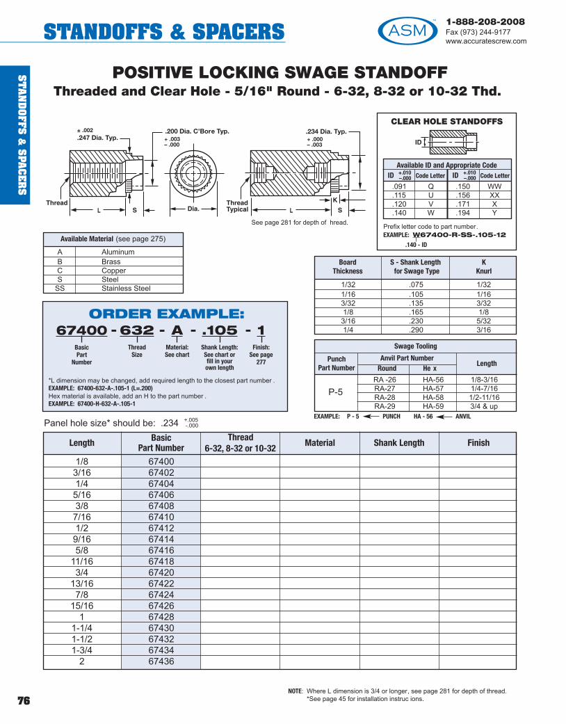
ST
AN
DO
FFS &
SPA
CE
RS
76
1-888-208-2008Fax (973) 244-9177www.accuratescrew.comSTANDOFFS & SPACERS
Length BasicPart Number
Thread6-32, 8-32 or 10-32
Material Shank Length Finish
POSITIVE LOCKING SWAGE STANDOFFThreaded and Clear Hole - 5/16" Round - 6-32, 8-32 or 10-32 Thd.
1/8 674003/16 674021/4 674045/16 674063/8 674087/16 674101/2 674129/16 674145/8 67416
11/16 674183/4 67420
13/16 674227/8 67424
15/16 674261 67428
1-1/4 674301-1/2 674321-3/4 67434
2 67436
NOTE: Where L dimension is 3/4 or longer, see page 281 for depth of thread.*See page 45 for installation instruc ions.
Panel hole size* should be: .234 +.005-.000
A AluminumB BrassC CopperS Steel
SS Stainless Steel
Available Material (see page 275)
EXAMPLE: P - 5 PUNCH HA - 56 ANVIL
RA -26 HA-56 1/8-3/16RA-27 HA-57 1/4-7/16RA-28 HA-58 1/2-11/16RA-29 HA-59 3/4 & up
Swage Tooling
P-5
Punch Part Number
Anvil Part NumberRound He x
Length
See page 281 for depth of hread.
± .002.247 Dia. Typ.
.200 Dia. C’Bore Typ.+ .003– .000
.234 Dia. Typ.+ .000– .003
ORDER EXAMPLE:67400
BasicPart
Number
632Thread
Size
AMaterial:See chart
.105Shank Length:See chart orfill in yourown length
1Finish:
See page277
----
*L dimension may be changed, add required length to the closest part number .EXAMPLE: 67400-632-A-.105-1 (L=.200)Hex material is available, add an H to the part number . EXAMPLE: 67400-H-632-A-.105-1
CLEAR HOLE STANDOFFS
Available ID and Appropriate CodeID Code Letter ID Code Letter
.091 Q .150 WW
.115 U .156 XX
.120 V .171 X
.140 W .194 Y
+.010–.000
+.010–.000
Prefix letter code to part number.EXAMPLE: W67400-R-SS-.105-12
.140 - ID
1/32 .075 1/321/16 .105 1/163/32 .135 3/321/8 .165 1/83/16 .230 5/321/4 .290 3/16
BoardThickness
S - Shank Lengthfor Swage Type
KKnurl

ST
AN
DO
FFS
&S
PAC
ER
S
77
1-888-208-2008Fax (973) 244-9177
www.accuratescrew.com STANDOFFS & SPACERS
Length BasicPart Number
Thread6-32, 8-32 or 10-32
Material Shank Length Finish
POSITIVE LOCKING SWAGE STANDOFFThreaded and Clear Hole - 11/32" Round - 6-32, 8-32 or 10-32 Thd.
1/8 674503/16 674521/4 674545/16 674563/8 674587/16 674601/2 674629/16 674645/8 67466
11/16 674683/4 67470
13/16 674727/8 67474
15/16 674761 67478
1-1/4 674801-1/2 674821-3/4 67484
2 67486
Panel hole size* should be: .250 +.005-.000
NOTE: Where L dimension is 3/4 or longer, see page 281 for depth of thread.*See page 45 for installation instructions.
A AluminumB BrassC CopperS Steel
SS Stainless Steel
Available Material (see page 275)
STAKING TOOLSARE NOT AVAILABLE
FOR THIS PART NUMBER
See page 281 for depth of thread.
± .002.263 Dia. Typ.
.213 Dia. C’Bore Typ.± .002
.250 Dia. Typ.+ .000– .004
1/32 .075 1/321/16 .105 1/163/32 .135 3/321/8 .165 1/83/16 .230 5/321/4 .290 3/16
BoardThickness
S - Shank Lengthfor Swage Type
KKnurl
CLEAR HOLE STANDOFFS
Available ID and Appropriate CodeID Code Letter ID Code Letter
.091 Q .150 WW
.115 U .156 XX
.120 V .171 X
.140 W
+.010–.000
+.010–.000
Prefix letter code to part number.EXAMPLE: W67450-R-SS-.105-12
.140 - ID
ORDER EXAMPLE:67450
BasicPart
Number
632Thread
Size
AMaterial:See chart
.105Shank Length:See chart orfill in yourown length
1Finish:
See page277
----
*L dimension may be changed, add required length to the closest part number .EXAMPLE: 67452-632-A-.105-1 (L=.200)
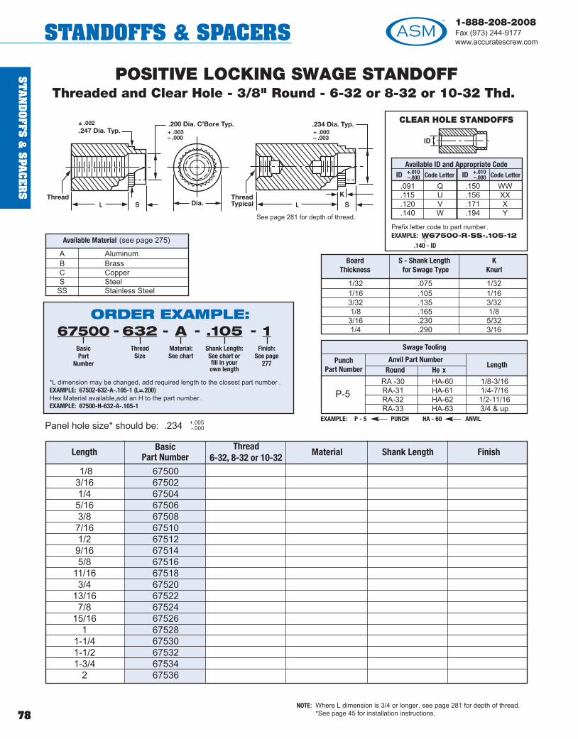
ST
AN
DO
FFS &
SPA
CE
RS
78
1-888-208-2008Fax (973) 244-9177www.accuratescrew.comSTANDOFFS & SPACERS
Length BasicPart Number
Thread6-32, 8-32 or 10-32
Material Shank Length Finish
POSITIVE LOCKING SWAGE STANDOFFThreaded and Clear Hole - 3/8" Round - 6-32 or 8-32 or 10-32 Thd.
1/8 675003/16 675021/4 675045/16 675063/8 675087/16 675101/2 675129/16 675145/8 67516
11/16 675183/4 67520
13/16 675227/8 67524
15/16 675261 67528
1-1/4 675301-1/2 675321-3/4 67534
2 67536
Panel hole size* should be: .234 +.005-.000
NOTE: Where L dimension is 3/4 or longer, see page 281 for depth of thread.*See page 45 for installation instructions.
A AluminumB BrassC CopperS Steel
SS Stainless Steel
Available Material (see page 275)
EXAMPLE: P - 5 PUNCH HA - 60 ANVIL
RA -30 HA-60 1/8-3/16RA-31 HA-61 1/4-7/16RA-32 HA-62 1/2-11/16RA-33 HA-63 3/4 & up
Swage Tooling
P-5
Punch Part Number
Anvil Part NumberRound He x
Length
See page 281 for depth of thread.
± .002.247 Dia. Typ.
.200 Dia. C’Bore Typ.+ .003– .000
.234 Dia. Typ.+ .000– .003
ORDER EXAMPLE:67500
BasicPart
Number
632Thread
Size
AMaterial:See chart
.105Shank Length:See chart orfill in yourown length
1Finish:
See page277
----
*L dimension may be changed, add required length to the closest part number .EXAMPLE: 67502-632-A-.105-1 (L=.200)Hex Material available,add an H to the part number . EXAMPLE: 67500-H-632-A-.105-1
CLEAR HOLE STANDOFFS
Available ID and Appropriate CodeID Code Letter ID Code Letter
.091 Q .150 WW
.115 U .156 XX
.120 V .171 X
.140 W .194 Y
+.010–.000
+.010–.000
Prefix letter code to part number.EXAMPLE: W67500-R-SS-.105-12
.140 - ID
1/32 .075 1/321/16 .105 1/163/32 .135 3/321/8 .165 1/83/16 .230 5/321/4 .290 3/16
BoardThickness
S - Shank Lengthfor Swage Type
KKnurl

ST
AN
DO
FFS
&S
PAC
ER
S
79
1-888-208-2008Fax (973) 244-9177
www.accuratescrew.com STANDOFFS & SPACERS
Length Thread BasicPart Number H or R or S Material Shank Length Finish
1/8 2-56 9010005/32 2-56 9010023/16 2-56 9010041/4 2-56 9010065/16 2-56 9010083/8 2-56 9010107/16 2-56 9010121/2 2-56 9010149/16 2-56 9010165/8 2-56 901018
11/16 2-56 9010203/4 2-56 901022
13/16 2-56 9010247/8 2-56 901026
15/16 2-56 9010281 2-56 901030
1-3/16 2-56 9010321-1/4 2-56 9010341-3/8 2-56 9010361-1/2 2-56 9010381-3/4 2-56 901040
2 2-56 901042
KNURLED STANDOFFSThreaded and Clear Hole - 3/16" Hex, Round or Squar e - 2-56 Thd.
Panel hole size** should be: .140 +.005-.000
A AluminumB BrassC CopperS Steel
SS Stainless Steel
Available Material(see page 275)
Available ID and Appropriate Code
ID Code Letter
.070 P
.091 Q
.115 U
+.010–.000
EXAMPLE: P - 3 PUNCH HA - 48 ANVIL
RA -18 HA-48 1/8-3/16RA-19 HA-49 1/4-7/16RA-20 HA-50 1/2-11/16RA-21 HA-51 3/4 & up
Swage Tooling
P-3
Punch Part Number
Anvil Part NumberRound He x
Length
NOTE: Where L dimension is 3/4 or longer, see page 281 for depth of thread.**See page 45 for installation instructions.
2-56Thread
3/16
C’Bore .115 Typ.
.152 ± .002
+ .003– .000
ORDER EXAMPLE:901000
BasicPart
Number
HHex (H),
Round (R) orSquare (S)
SSMaterial:See chart
.105Shank Length:See chart orfill in yourown length
1Finish:
See page277
----
*L dimension may be changed, add required length to the closest part number .EXAMPLE: 901014-R-SS-.105-12 (L=.525)
CLEAR HOLE STANDOFFS
Prefix letter code to part number.EXAMPLE: P901000-R-SS-.105-12
.070 - ID
BoardThickness
RecommendedShank Length
for Swage
1/32 .0751/16 .1053/32 .1351/8 .1653/16 .2301/4 .290

ST
AN
DO
FFS &
SPA
CE
RS
80
1-888-208-2008Fax (973) 244-9177www.accuratescrew.comSTANDOFFS & SPACERS
Length Thread BasicPart Number H or R or S Material Shank Length Finish
KNURLED STANDOFFSThreaded and Clear Hole - 3/16" Hex, Round or Squar e - 4-40 Thd.
Panel hole size** should be: .140 +.005-.000
A AluminumB BrassC CopperS Steel
SS Stainless Steel
Available Material(see page 275)
Available ID and Appropriate Code
ID Code Letter
.070 P
.091 Q
.115 U
+.010–.000
EXAMPLE: P - 3 PUNCH HA - 48 ANVIL
RA -18 HA-48 1/8-3/16RA-19 HA-49 1/4-7/16RA-20 HA-50 1/2-11/16RA-21 HA-51 3/4 & up
Swage Tooling
P-3
Punch Part Number
Anvil Part NumberRound He x
Length
NOTE: Where L dimension is 3/4 or longer, see page 281 for depth of thread.**See page 45 for installation instructions.
ORDER EXAMPLE:901084
BasicPart
Number
HHex (H),
Round (R) orSquare (S)
SSMaterial:See chart
.105Shank Length:See chart orfill in yourown length
1Finish:
See page277
----
*L dimension may be changed, add required length to the closest part number .EXAMPLE: 901098-R-SS-.105-12 (L=.525)
CLEAR HOLE STANDOFFS
Prefix letter code to part number.EXAMPLE: P901084-R-SS-.105-12
.070 - ID
BoardThickness
RecommendedShank Length
for Swage
1/32 .0751/16 .1053/32 .1351/8 .1653/16 .2301/4 .290
4-40Thread
3/16
C’Bore .115 Typ.
.152 ± .002
+ .003– .000
3/32 4-40 9010841/8 4-40 9010863/16 4-40 9010881/4 4-40 9010905/16 4-40 9010923/8 4-40 9010947/16 4-40 9010961/2 4-40 9010989/16 4-40 9011005/8 4-40 901102
11/16 4-40 9011043/4 4-40 901106
13/16 4-40 9011087/8 4-40 9011101 4-40 901112
1-3/16 4-40 9011141-1/4 4-40 9011161-3/8 4-40 9011181-1/2 4-40 9011201-3/4 4-40 901122
2 4-40 901124

ST
AN
DO
FFS
&S
PAC
ER
S
81
1-888-208-2008Fax (973) 244-9177
www.accuratescrew.com STANDOFFS & SPACERS
Length Thread BasicPart Number H or R or S Material Shank Length Finish
1/8 4-40 9010443/16 4-40 9010461/4 4-40 9010485/16 4-40 9010503/8 4-40 9010527/16 4-40 9010541/2 4-40 9010569/16 4-40 9010585/8 4-40 901060
11/16 4-40 9010623/4 4-40 901064
13/16 4-40 9010667/8 4-40 901068
15/16 4-40 9010701 4-40 901072
1-1/8 4-40 9010741-1/4 4-40 9010761-1/2 4-40 9010781-3/4 4-40 901080
2 4-40 901082
KNURLED STANDOFFSThreaded and Clear Hole - 1/4" Hex, Round or Squar e - 4-40 Thd.
Panel hole size** should be: .188 + 005-.000
A AluminumB BrassC CopperS Steel
SS Stainless Steel
Available Material(see page 275)
EXAMPLE: P - 4 PUNCH HA - 52 ANVIL
RA -22 HA-52 1/8-3/16RA-23 HA-53 1/4-7/16RA-24 HA-54 1/2-11/16RA-25 HA-55 3/4 & up
Swage Tooling
P-4
Punch Part Number
Anvil Part NumberRound He x
Length
NOTE: Where L dimension is 3/4 or longer, see page 281 for depth of thread.**See page 45 for installation instructions.
ORDER EXAMPLE:901044
BasicPart
Number
HHex (H),
Round (R) orSquare (S)
SSMaterial:See chart
.105Shank Length:See chart orfill in yourown length
1Finish:
See page277
----
*L dimension may be changed, add required length to the closest part number .EXAMPLE: 901056-R-SS-.105-12 (L=.525)
BoardThickness
RecommendedShank Length
for Swage
1/32 .0751/16 .1053/32 .1351/8 .1653/16 .2301/4 .290
4-40Thread
1/4
C’Bore .150 Typ.
.201 ± .002
+ .003– .001
CLEAR HOLE STANDOFFS
Available ID and Appropriate CodeID Code Letter ID Code Letter
.070 P .140 W
.091 Q .150 WW
.115 U .156 XX
.120 V
+.010–.000
+.010–.000
Prefix letter code to part number.EXAMPLE: P901044-R-SS-.105-12
.070 - ID

ST
AN
DO
FFS &
SPA
CE
RS
82
1-888-208-2008Fax (973) 244-9177www.accuratescrew.comSTANDOFFS & SPACERS
Length Thread BasicPart Number H or R or S Material Shank Length Finish
1/8 6-32 9011263/16 6-32 9011287/32 6-32 9011301/4 6-32 9011329/32 6-32 9011345/16 6-32 90113611/32 6-32 9011383/8 6-32 9011407/16 6-32 9011421/2 6-32 9011449/16 6-32 9011465/8 6-32 901148
11/16 6-32 9011503/4 6-32 901152
13/16 6-32 9011547/8 6-32 901156
15/16 6-32 9011581 6-32 901160
1-1/8 6-32 9011621-1/4 6-32 9011641-3/8 6-32 9011661-1/2 6-32 9011681-3/4 6-32 901170
2 6-32 901172
KNURLED STANDOFFSThreaded and Clear Hole - 1/4" Hex, Round or Squar e - 6-32 Thd.
Panel hole size** should be: .188 +.005-.000
A AluminumB BrassC CopperS Steel
SS Stainless Steel
Available Material(see page 275)
NOTE: Where L dimension is 3/4 or longer, see page 281 for depth of thread.**See page 45 for installation instructions.
ORDER EXAMPLE:901126
BasicPart
Number
HHex (H),
Round (R) orSquare (S)
SSMaterial:See chart
.105Shank Length:See chart orfill in yourown length
1Finish:
See page277
----
*L dimension may be changed, add required length to the closest part number .EXAMPLE: 901144-R-SS-.105-12 (L=.525)
BoardThickness
RecommendedShank Length
for Swage
1/32 .0751/16 .1053/32 .1351/8 .1653/16 .2301/4 .290
6-32Thread
1/4
C’Bore .150 Typ.
.201 ± .002
+ .003– .001
EXAMPLE: P - 4 PUNCH HA - 52 ANVIL
RA -22 HA-52 1/8-3/16RA-23 HA-53 1/4-7/16RA-24 HA-54 1/2-11/16RA-25 HA-55 3/4 & up
Swage Tooling
P-4
Punch Part Number
Anvil Part NumberRound He x
Length
CLEAR HOLE STANDOFFS
Available ID and Appropriate CodeID Code Letter ID Code Letter
.091 Q .140 W
.115 U .150 WW
.120 V .156 XX
+.010–.000
+.010–.000
Prefix letter code to part number.EXAMPLE: W901126-R-SS-.105-12
.140 - ID

ST
AN
DO
FFS
&S
PAC
ER
S
83
1-888-208-2008Fax (973) 244-9177
www.accuratescrew.com STANDOFFS & SPACERS
Length Thread BasicPart Number H or R or S Material Shank Length Finish
1/8 6-32 9011743/16 6-32 9011761/4 6-32 9011785/16 6-32 9011803/8 6-32 9011827/16 6-32 9011841/2 6-32 9011869/16 6-32 9011885/8 6-32 901190
11/16 6-32 9011923/4 6-32 901194
13/16 6-32 9011967/8 6-32 9011981 6-32 901200
1-1/8 6-32 9012021-1/4 6-32 9012041-1/2 6-32 9012061-3/4 6-32 901208
2 6-32 901210
KNURLED STANDOFFSThreaded and Clear Hole - 5/16" Hex, Round or Square - 6-32 Thd.
Panel hole size** should be: .234 +.005-.000
A AluminumB BrassC CopperS Steel
SS Stainless Steel
Available Material(see page 275)
EXAMPLE: P - 5 PUNCH HA - 56 ANVIL
RA -26 HA-56 1/8-3/16RA-27 HA-57 1/4-7/16RA-28 HA-58 1/2-11/16RA-29 HA-59 3/4 & up
Swage Tooling
P-5
Punch Part Number
Anvil Part NumberRound He x
Length
NOTE: Where L dimension is 3/4 or longer, see page 281 for depth of thread.**See page 45 for installation instructions.
ORDER EXAMPLE:901174
BasicPart
Number
HHex (H),
Round (R) orSquare (S)
SSMaterial:See chart
.105Shank Length:See chart orfill in yourown length
1Finish:
See page277
----
*L dimension may be changed, add required length to the closest part number .EXAMPLE: 901186-R-SS-.105-12 (L=.525)
BoardThickness
RecommendedShank Length
for Swage
1/32 .0751/16 .1053/32 .1351/8 .1653/16 .2301/4 .290
6-32Thread
5/16
C’Bore .200 Typ.
.247 ± .002
+ .003– .000
CLEAR HOLE STANDOFFS
Available ID and Appropriate CodeID Code Letter ID Code Letter
.091 Q .150 WW
.115 U .156 XX
.120 V .171 X
.140 W .194 Y
+.010–.000
+.010–.000
Prefix letter code to part number.EXAMPLE: W901174-R-SS-.105-12
.140 - ID

ST
AN
DO
FFS &
SPA
CE
RS
84
1-888-208-2008Fax (973) 244-9177www.accuratescrew.comSTANDOFFS & SPACERS
Length Thread BasicPart Number H or R or S Material Shank Length Finish
1/8 8-32 9012125/32 8-32 9012143/16 8-32 9012161/4 8-32 9012185/16 8-32 9012203/8 8-32 9012227/16 8-32 9012241/2 8-32 9012269/16 8-32 9012285/8 8-32 901230
11/16 8-32 9012323/4 8-32 901234
13/16 8-32 9012367/8 8-32 9012381 8-32 901240
1-1/8 8-32 9012421-1/4 8-32 9012441-1/2 8-32 9012461-3/4 8-32 901248
2 8-32 901250
KNURLED STANDOFFSThreaded and Clear Hole - 5/16" Hex, Round or Squar e - 8-32 Thd.
Panel hole size** should be: .234 +.005-.000
A AluminumB BrassC CopperS Steel
SS Stainless Steel
Available Material(see page 275)
NOTE: Where L dimension is 3/4 or longer, see page 281 for depth of thread.**See page 45 for installation instructions.
ORDER EXAMPLE:901212
BasicPart
Number
HHex (H),
Round (R) orSquare (S)
SSMaterial:See chart
.105Shank Length:See chart orfill in yourown length
1Finish:
See page277
----
*L dimension may be changed, add required length to the closest part number .EXAMPLE: 901212-R-SS-.105-12 (L=.525)
BoardThickness
RecommendedShank Length
for Swage
1/32 .0751/16 .1053/32 .1351/8 .1653/16 .2301/4 .290
8-32Thread
5/16
C’Bore .200 Typ.
.247 ± .002
+ .003– .000
EXAMPLE: P - 5 PUNCH HA - 56 ANVIL
RA -26 HA-56 1/8-3/16RA-27 HA-57 1/4-7/16RA-28 HA-58 1/2-11/16RA-29 HA-59 3/4 & up
Swage Tooling
P-5
Punch Part Number
Anvil Part NumberRound He x
Length
CLEAR HOLE STANDOFFS
Available ID and Appropriate CodeID Code Letter ID Code Letter
.091 Q .150 WW
.115 U .156 XX
.120 V .171 X
.140 W .194 Y
+.010–.000
+.010–.000
Prefix letter code to part number.EXAMPLE: W901212-R-SS-.105-12
.140 - ID

ST
AN
DO
FFS
&S
PAC
ER
S
85
1-888-208-2008Fax (973) 244-9177
www.accuratescrew.com STANDOFFS & SPACERS
Length Thread BasicPart Number H or R or S Material Shank Length Finish
1/8 10-32 9012525/32 10-32 9012543/16 10-32 9012561/4 10-32 9012585/16 10-32 9012603/8 10-32 9012627/16 10-32 9012641/2 10-32 9012669/16 10-32 9012685/8 10-32 901270
11/16 10-32 9012723/4 10-32 901274
13/16 10-32 9012767/8 10-32 9012781 10-32 901280
1-1/8 10-32 9012821-1/4 10-32 9012841-1/2 10-32 9012861-3/4 10-32 901288
2 10-32 901290
KNURLED STANDOFFSThreaded and Clear Hole - 5/16" Hex, Round or Squar e - 10-32 Thd.
Panel hole size** should be: .234 +.005-.000
A AluminumB BrassC CopperS Steel
SS Stainless Steel
Available Material(see page 275)
NOTE: Where L dimension is 3/4 or longer, see page 281 for depth of thread.**See page 45 for installation instructions.
ORDER EXAMPLE:901252
BasicPart
Number
HHex (H),
Round (R) orSquare (S)
SSMaterial:See chart
.105Shank Length:See chart orfill in yourown length
1Finish:
See page277
----
*L dimension may be changed, add required length to the closest part number .EXAMPLE: 901266-R-SS-.105-12 (L=.525)
BoardThickness
RecommendedShank Length
for Swage
1/32 .0751/16 .1053/32 .1351/8 .1653/16 .2301/4 .290
10-32Thread
5/16
C’Bore .200 Typ.
.247 ± .002
+ .003– .000
EXAMPLE: P - 5 PUNCH HA - 56 ANVIL
RA -26 HA-56 1/8-3/16RA-27 HA-57 1/4-7/16RA-28 HA-58 1/2-11/16RA-29 HA-59 3/4 & up
Swage Tooling
P-5
Punch Part Number
Anvil Part NumberRound He x
Length
CLEAR HOLE STANDOFFS
Available ID and Appropriate CodeID Code Letter ID Code Letter
.091 Q .150 WW
.115 U .156 XX
.120 V .171 X
.140 W .194 Y
+.010–.000
+.010–.000
Prefix letter code to part number.EXAMPLE: W901252-R-SS-.105-12
.140 - ID

ST
AN
DO
FFS &
SPA
CE
RS
86
1-888-208-2008Fax (973) 244-9177www.accuratescrew.comSTANDOFFS & SPACERS
Length Thread BasicPart Number H or R or S Material Shank Length Finish
1/8 6-32 9012923/16 6-32 9012941/4 6-32 9012965/16 6-32 9013003/8 6-32 9012987/16 6-32 9013021/2 6-32 9013049/16 6-32 9013065/8 6-32 901308
11/16 6-32 9013103/4 6-32 901312
13/16 6-32 9013147/8 6-32 9013161 6-32 901318
1-1/8 6-32 9013201-1/4 6-32 9013221-1/2 6-32 9013241-3/4 6-32 901326
2 6-32 901328
KNURLED STANDOFFSThreaded and Clear Hole - 3/8" Hex, Round or Squar e - 6-32 Thd.
Panel hole size** should be: .234 +.005-.000
A AluminumB BrassC CopperS Steel
SS Stainless Steel
Available Material(see page 275)
NOTE: Where L dimension is 3/4 or longer, see page 281 for depth of thread.**See page 45 for installation instructions.
ORDER EXAMPLE:901292
BasicPart
Number
HHex (H),
Round (R) orSquare (S)
SSMaterial:See chart
.105Shank Length:See chart orfill in yourown length
1Finish:
See page277
----
*L dimension may be changed, add required length to the closest part number .EXAMPLE: 901304-R-SS-.105-12 (L=.525)
BoardThickness
RecommendedShank Length
for Swage
1/32 .0751/16 .1053/32 .1351/8 .1653/16 .2301/4 .290
6-32Thread
3/8
C’Bore .200 Typ.
.247 ± .002
+ .003– .000
EXAMPLE: P - 5 PUNCH HA - 60 ANVIL
RA -30 HA-60 1/8-3/16RA-31 HA-61 1/4-7/16RA-32 HA-62 1/2-11/16RA-33 HA-63 3/4 & up
Swage Tooling
P-5
Punch Part Number
Anvil Part NumberRound He x
Length
CLEAR HOLE STANDOFFS
Available ID and Appropriate CodeID Code Letter ID Code Letter
.091 Q .150 WW
.115 U .156 XX
.120 V .171 X
.140 W .194 Y
+.010–.000
+.010–.000
Prefix letter code to part number.EXAMPLE: W901292-R-SS-.105-12
.140 - ID

ST
AN
DO
FFS
&S
PAC
ER
S
87
1-888-208-2008Fax (973) 244-9177
www.accuratescrew.com STANDOFFS & SPACERS
Length Thread BasicPart Number H or R or S Material Shank Length Finish
1/8 8-32 9013303/16 8-32 9013321/4 8-32 9013345/16 8-32 9013363/8 8-32 9013387/16 8-32 9013401/2 8-32 9013429/16 8-32 9013445/8 8-32 901346
11/16 8-32 9013483/4 8-32 901350
13/16 8-32 9013527/8 8-32 9013541 8-32 901356
1-1/8 8-32 9013581-1/4 8-32 9013601-1/2 8-32 9013621-3/4 8-32 901364
2 8-32 901366
KNURLED STANDOFFSThreaded and Clear Hole - 3/8" Hex, Round or Squar e - 8-32 Thd.
Panel hole size** should be: .234 +.005-.000
A AluminumB BrassC CopperS Steel
SS Stainless Steel
Available Material(see page 275)
NOTE: Where L dimension is 3/4 or longer, see page 281 for depth of thread.**See page 45 for installation instructions.
ORDER EXAMPLE:901330
BasicPart
Number
HHex (H),
Round (R) orSquare (S)
SSMaterial:See chart
.105Shank Length:See chart orfill in yourown length
1Finish:
See page277
----
*L dimension may be changed, add required length to the closest part number .EXAMPLE: 901342-R-SS-.105-12 (L=.525)
BoardThickness
RecommendedShank Length
for Swage
1/32 .0751/16 .1053/32 .1351/8 .1653/16 .2301/4 .290
EXAMPLE: P - 5 PUNCH HA - 60 ANVIL
RA -30 HA-60 1/8-3/16RA-31 HA-61 1/4-7/16RA-32 HA-62 1/2-11/16RA-33 HA-63 3/4 & up
Swage Tooling
P-5
Punch Part Number
Anvil Part NumberRound He x
Length
CLEAR HOLE STANDOFFS
Available ID and Appropriate CodeID Code Letter ID Code Letter
.091 Q .150 WW
.115 U .156 XX
.120 V .171 X
.140 W .194 Y
+.010–.000
+.010–.000
Prefix letter code to part number.EXAMPLE: W901330-R-SS-.105-12
.140 - ID
8-32Thread
3/8
C’Bore .200 Typ.
.247 ± .002
+ .003– .000

ST
AN
DO
FFS &
SPA
CE
RS
88
1-888-208-2008Fax (973) 244-9177www.accuratescrew.comSTANDOFFS & SPACERS
Length Thread BasicPart Number H or R or S Material Shank Length Finish
1/8 10-32 9013683/16 10-32 9013701/4 10-32 9013725/16 10-32 9013743/8 10-32 9013767/16 10-32 9013781/2 10-32 9013809/16 10-32 9013825/8 10-32 901384
11/16 10-32 9013863/4 10-32 901388
13/16 10-32 9013907/8 10-32 9013921 10-32 901394
1-1/8 10-32 9013961-1/4 10-32 9013981-1/2 10-32 9014001-3/4 10-32 901402
2 10-32 901404
KNURLED STANDOFFSThreaded and Clear Hole - 3/8" Hex, Round or Squar e - 10-32 Thd.
Panel hole size** should be: .234 +.005-.000
A AluminumB BrassC CopperS Steel
SS Stainless Steel
Available Material(see page 275)
NOTE: Where L dimension is 3/4 or longer, see page 281 for depth of thread.**See page 45 for installation instructions.
ORDER EXAMPLE:901368
BasicPart
Number
HHex (H),
Round (R) orSquare (S)
SSMaterial:See chart
.105Shank Length:See chart orfill in yourown length
1Finish:
See page277
----
*L dimension may be changed, add required length to the closest part number .EXAMPLE: 901380-R-SS-.105-12 (L=.525)
BoardThickness
RecommendedShank Length
for Swage
1/32 .0751/16 .1053/32 .1351/8 .1653/16 .2301/4 .290
EXAMPLE: P - 5 PUNCH HA - 60 ANVIL
RA -30 HA-60 1/8-3/16RA-31 HA-61 1/4-7/16RA-32 HA-62 1/2-11/16RA-33 HA-63 3/4 & up
Swage Tooling
P-5
Punch Part Number
Anvil Part NumberRound He x
Length
CLEAR HOLE STANDOFFS
Available ID and Appropriate CodeID Code Letter ID Code Letter
.091 Q .150 WW
.115 U .156 XX
.120 V .171 X
.140 W .194 Y
+.010–.000
+.010–.000
Prefix letter code to part number.EXAMPLE: W901368-R-SS-.105-12
.140 - ID
10-32Thread
3/8
C’Bore .200 Typ.
.247 ± .002
+ .003– .000

ST
AN
DO
FFS
&S
PAC
ER
S
89
1-888-208-2008Fax (973) 244-9177
www.accuratescrew.com STANDOFFS & SPACERS
BLIND THREADED HOLE STANDOFFS
NOTES: Depth of thread will vary in shorter lengths L. The maximum depth, minimum of 1-1/2 threads for shear length, will be threaded .
0-80 .187 Min. Full Thread A2-56 .187 Min. Full Thread B3-48 .187 Min. Full Thread C4-40 .250 Min. Full Thread H6-32 .375 Min. Full Thread I8-32 .437 Min. Full Thread S
10-32 .500 Min. Full Thread K1/4-20 .500 Min. Full Thread L
Thread Depth of Blind Hole Code
0-80 .187 Min. Full Thread AA2-56 .187 Min. Full Thread BB3-48 .187 Min. Full Thread CC4-40 .250 Min. Full Thread HH6-32 .375 Min. Full Thread II8-32 .437 Min. Full Thread SS
10-32 .500 Min. Full Thread KK1/4-20 .500 Min. Full Thread LL
Thread Depth of Blind Hole Code
ORDER EXAMPLE:
Refer to Threaded Standoffs on page 46-88 for basic configuration, specifications, material, etc.Add letter designation to part number according to the charts.
HBlind Hole Depth:
See chart
HHex (H),
Round (R)or Square (S)
AMaterial:
See chart onStandoff page
13010BasicPart
Number
.075Shank Length:See chart or
fill in your ownlength
1Finish:
See page277
HTHi-Torque
Option
- -- - - -
ORDER EXAMPLE:
Refer to Threaded Standoffs on pages 46-88 for basic configuration, specifications, material, etc.Add letter designation to part number according to the charts.
HHBlind Hole Depth:
See chart
HHex (H),
Round (R)or Square (S)
AMaterial:
See chart onStandoff page
13010BasicPart
Number
.075Shank Length:See chart or
fill in your ownlength
1Finish:
See page277
HTHi-Torque
Option
- -- - - -
! TECH TIPFor flush flaring into counter-sink hole, use a shanklength of .020 shorter than board thickness.

ST
AN
DO
FFS &
SPA
CE
RS
90
1-888-208-2008Fax (973) 244-9177www.accuratescrew.comSTANDOFFS & SPACERS
Clearance Hole
LetterDesignation
FACE KNURLED THREADED STANDOFFS
FACE KNURLED CLEAR HOLE STANDOFFS
.091 Q
.098 QQ
.115 U
.120 V
.140 W
.150 WW
.156 XX
.171 X
.194 Y
.215 Z
.257 ZZ
ORDER EXAMPLE:
Refer to Threaded/Clear Hole Standoffs on pages 46-71 for basic part number , basic configurations, specifications, material, etc. Add letter designation J to part number for Knurled.
JKnurled
HHex (H),
Round (R)or Square (S)
AMaterial:
See chart onStandoff page
13010BasicPart
Number
.075Shank Length:See chart or
fill in your ownlength
1Finish:
See page277
- -- - -
ORDER EXAMPLE:
Refer to Threaded/Clear Hole Standoffs on pages 46-71 for basic part number , basic configurations,specifica ions, material, etc.
Add letter designation J to part number for Knurled. Add letter designation to part number for Clearance Hole according to the chart.
JKnurled
HHex (H),
Round (R)or Square (S)
AMaterial:
See chart onStandoff page
13010BasicPart
Number
.075Shank Length:See chart or
fill in your ownlength
1Finish:
See page277
- -- - -QClearance
Hole:See chart
-
Visit us on the Web atwww.accuratescrew.com

ST
AN
DO
FFS
&S
PAC
ER
S
91
1-888-208-2008Fax (973) 244-9177
www.accuratescrew.com STANDOFFS & SPACERS
HINGED STANDOFF FOR TERMINAL BOARDS
20094 4-40 .187 3/4 .172 .375 .37520095 4-40 .187 1 .250 .375 .62520095A 4-40 .187 1-1/4 .250 .625 .62520096 6-32 .250 3/4 .172 .375 .37520097 6-32 .250 1 .250 .375 .62520097A 6-32 .250 1-1/4 .250 .625 .62520098 8-32 .250 3/4 .172 .375 .37520099 8-32 .250 1 .250 .375 .62520099A 8-32 .250 1-1/4 .250 .625 .625
PartNumber
TThread
DDiameter
LLength A B C
PartNumber
TThread
LLength
DDiameter A B
20074 4-40 .625 .187 .250 .172 .250 .37520076 4-40 .875 .187 .250 .250 .250 .62520078 6-32 .625 .250 .312 .172 .250 .37520080 6-32 .875 .250 .312 .250 .250 .62520082 8-32 .625 .250 .312 .172 .250 .37520084 8-32 .875 .250 .312 .250 .250 .625
PartNumber
TThread
LLength
DDiameter E A C B
20088 4-40 1/2 .187 .250 .25020090 6-32 1/2 .250 .312 .25020092 8-32 1/2 .250 .312 .250
ORDER EXAMPLE:20088
BasicPart
Number
Finish Material
Cadmium plate per QQ-P-416 class 2, type 2 and gold iridite
Made of brassmil. spec. QQ-B-626Acomp. 22-1/2 hard

92
1-888-208-2008Fax (973) 244-9177www.accuratescrew.comLOCKING FASTENERS
LOC
KIN
G FA
ST
EN
ER
S
HI-TORQUE LOCKING FASTENERSApplications and Installations
Hi-Torque Fasteners Offer A NumberOf Advantages In A Wide Variety Of Styles• Wear and corrosion resistant• Magnetic carbon and stainless steel for strong
threads and maximum life• Simplified design• No loose nuts, washers or lock pins• Easy to install with ordinary tools
Hi-Torque Locking FastenerApplications Are Virtually UnlimitedTheir integral, captivated design speeds handling andassembly operations in a wide variety of applications inthe electronic, instrument, aircraft and other industries.The ability of these fasteners to provide long-wearingstainless steel threads for aluminum, brass, mild steel,thermoplastic panels or chassis makes them ideal forfastening components, terminal boards, wire and cableharnesses, circuit boards, tube sockets and sub-
assemblies. Their extreme durability makes them a mustwhere repeated fastening and unfastening takes place.The unified design of the Floating Nuts simplifies adjustinghole misalignments, particularly in difficult-to-reach places.Self-locking styles provide added resistance to vibrationand shock in fastening applications.
Installation• No special tools or chassis preparations required• Drilled or punched hole• Insert into the prescribed size hole• Press into place
DRILLAND
PRESS
STANDOFFS NUTS STUDS
Miniature . . . . . . . .93
Knurled . . . . . .94-95
Flush . . . . . . . . . . .96
Reverse Flush . . . .97
Blind . . . . . . . . . . .98
Flush Style I ............99
Flush Style II .........100
Hex Extension .......101
Round Extension ...101
Blind .............102-103
Spline Press..........104
Spline PressExtension..............105
Blind Press ...........106
Flush ....................107
Concealed Head....108

Superior fastening performanceis provided by the miniaturepress nut through strong,permanent, wear-resistantthreads for soft brass,aluminum, mild steel, orthermoplastic panels, part orchassis. Thread depth and
load retention is made constant regardless of sheetmaterial or thickness. Extension E provides additionalthreads for thin, brittle materials.
Threads provided are class 2B, MIL-S-7742 formaterials of Rockwell hardness 70 or less (stainlesssteel nuts) and 85 or less (carbon steel nuts) for holesizes .108 up to .150.
Typical retention forces are 150 lbs. push-out, and 25inch lbs. torque-out in standard chassis aluminum.
Captive hardware facilitates easy one-side installing forassemblies in normally hard-to-reach places.
Steel Inserts: for use in low carbon steels that are 1/2hard or softer and for stainless steel in the annealedcondition.
Stainless steel inserts: for use in most aluminums or inlow carbon steels that are 1/4 hard or softer .
The Cadmium Plate Finish (7) for Carbon Steel and the Passivate Finish (12) for Stainless Steel isrecommended.
Tolerances (unless noted): Decimals ± .005, Frac ±1/64
MINIATURE STANDOFFSHi-Torque Locking Fasteners
66060 0-80 .030 .032-.03966062 0-80 .038 .040-up66064 1-64 .030 .032-.03966066 1-64 .038 .040-up66068 2-56 .030 .032-.03966070 2-56 .038 .040-up66072 3-48 .030 .032-.03966074 3-48 .038 .040-up
3/64
S Carbon Steel SS Stainless Steel
Available Material (see page 275)
ORDER EXAMPLE:66060
BasicPart
Number
SSMaterial:See chart
12Finish:
See page277
- -
BasicPart No.
ThreadSize
DMax
SheetThickness
Hole Size in Sheet
AMax
CDia
BLength
.109-.112 .108 11/64
.120-.123 .119 3/16
.136-.139 .135 13/64
.147-.150 .146 7/32
93
1-888-208-2008Fax (973) 244-9177
www.accuratescrew.com LOCKING FASTENERS
LOC
KIN
G F
AS
TE
NE
RS
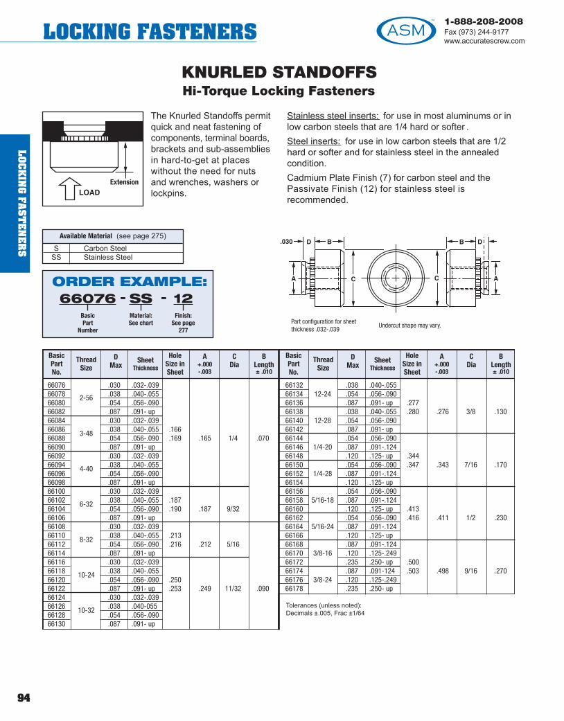
94
1-888-208-2008Fax (973) 244-9177www.accuratescrew.comLOCKING FASTENERS
LOC
KIN
G FA
ST
EN
ER
S
KNURLED STANDOFFSHi-Torque Locking Fasteners
The Knurled Standoffs permitquick and neat fastening ofcomponents, terminal boards,brackets and sub-assembliesin hard-to-get at placeswithout the need for nuts and wrenches, washers orlockpins.
Stainless steel inserts: for use in most aluminums or inlow carbon steels that are 1/4 hard or softer . Steel inserts: for use in low carbon steels that are 1/2hard or softer and for stainless steel in the annealedcondition.Cadmium Plate Finish (7) for carbon steel and thePassivate Finish (12) for stainless steel isrecommended.
Part configuration for sheetthickness .032-.039
Undercut shape may vary.
S Carbon Steel SS Stainless Steel
Available Material (see page 275)
ORDER EXAMPLE:66076
BasicPart
Number
SSMaterial:See chart
12Finish:
See page277
- -
Tolerances (unless noted):Decimals ±.005, Frac ±1/64
66076 .030 .032-.03966078 .038 .040-.05566080 .054 .056-.09066082 .087 .091- up66084 .030 .032-.03966086 .038 .040-.055 .16666088 .054 .056-.090 .169 .165 1/4 .07066090 .087 .091- up66092 .030 .032-.03966094 .038 .040-.05566096 .054 .056-.09066098 .087 .091- up66100 .030 .032-.03966102 .038 .040-.055 .18766104 .054 .056-.090 .190 .187 9/3266106 .087 .091- up66108 .030 .032-.03966110 .038 .040-.055 .21366112 .054 .056-.090 .216 .212 5/1666114 .087 .091- up66116 .030 .032-.03966118 .038 .040-.05566120 .054 .056-.090 .25066122 .087 .091- up .253 .249 11/32 .09066124 .030 .032-.03966126 .038 .040-05566128 .054 .056-.09066130 .087 .091- up
66132 .038 .040-.05566134 12-24 .054 .056-.09066136 .087 .091- up .27766138 .038 .040-.055 .280 .276 3/8 .13066140 12-28 .054 .056-.09066142 .087 .091- up66144 .054 .056-.09066146 1/4-20 .087 .091-.12466148 .120 .125- up .34466150 .054 .056-.090 .347 .343 7/16 .17066152 1/4-28 .087 .091-.12466154 .120 .125- up66156 .054 .056-.09066158 5/16-18 .087 .091-.12466160 .120 .125- up .41366162 .054 .056-.090 .416 .411 1/2 .23066164 5/16-24 .087 .091-.12466166 .120 .125- up66168 .087 .091-.12466170 3/8-16 .120 .125-.24966172 .235 .250- up .50066174 .087 .091-124 .503 .498 9/16 .27066176 3/8-24 .120 .125-.24966178 .235 .250- up
BasicPartNo.
ThreadSize
DMax
Sheet Thickness
HoleSize inSheet
A+.000-.003
CDia
BLength± .010
BasicPartNo.
ThreadSize
DMax
Sheet Thickness
HoleSize inSheet
A+.000-.003
CDia
BLength± .010
2-56
3-48
4-40
6-32
8-32
10-24
10-32

This fastener provides durablethreads for strong, uniformattachment at all points onpanels and chassis of varyingthickness and material.Extension E provides additionalthread length for thin panelwithout restricting flushmounting at the panel front.
Knurled Standof fs permit quick and neat fastening ofcomponents, terminal boards, brackets and sub-assemblies in hard-to-reach places without the need fornuts and wrenches, washers or lockpins.
KNURLED STANDOFFSHi-Torque Locking Fasteners
Available Material (see page 275)
Undercut shape may vary.
Aluminum 2011 T3
ORDER EXAMPLE:66180
BasicPart
Number
22Finish:
See page277
-
Tolerances (unless noted): Decimals +.005, Frac +1/64
661802-56
.038 .040 -.055 .166.165 .070
66182 .054 .056 - up .169 1/466184 4-40 .038 .040 -.055 .187
.18766186 .054 .056 - up .190
.09066188 6-32 .038 .040 -.055 .213
.212 9/3266190 .054 .056 - up .21666192 .038 .040 -.05566194 8-32 .054 .056 - up
.234.233 5/16 .130
66195 .087 .091 -.124.237
66196 10-24 .038 .040 -.05566198 .054 .056 - up .296 .295 3/8 .16066200 10-32 .038 .040 -.055 .29966202 .054 .056 - up66204 .054 .056 -.09066206 1/4-20 .087 .091 -.12466208 .120 .125 - up .344 .343 7/16 .17066210 .054 .056 -.090 .34766212 1/4-28 .087 .091 -.12466214 .120 .125 - up
66216 .054 .056 -.09066218 5/16-18 .087 .091 -.12466220 .120 .125 - up .413
.411 1/2 .23066222 .054 .056 -.090 .41666224 5/16-24 .087 .091 -12466226 .120 .125 - up66228 .087 .091 -.12466230 3/8-16 .120 .125 -.24966232 .235 .250 - up .500
.498 9/16 .27066234 .087 .091 -.124 .50366236 3/8-24 .120 .125 -.24966238 .235 .250 - up
BasicPartNo.
ThreadSize
D+.000-.005
Sheet Thickness
HoleSize inSheet
A+.000-.003
CDia
BLength± .010
BasicPartNo.
ThreadSize
D+.000-.005
Sheet Thickness
HoleSize inSheet
A+.000-.003
CDia
BLength± .010
95
1-888-208-2008Fax (973) 244-9177
www.accuratescrew.com LOCKING FASTENERS
LOC
KIN
G F
AS
TE
NE
RS

96
1-888-208-2008Fax (973) 244-9177www.accuratescrew.comLOCKING FASTENERS
LOC
KIN
G FA
ST
EN
ER
S
Material Finish
A Aluminum 7075-T6 None (1)SS 300 Stainless Steel Passivate (12)
These fasteners havean extended sectionwhich providesadditional securing-thread length and alsoserves as a threadedstandoff spacer formounting panels orbrackets to a chassis.These blind-thread-
seal press nuts protect against oil and moisturepenetration without the need for sealing washers. Thru-threaded units permit two-ended mounting; extensionon one end, flush-to-panel on the other .
Corrosion-proof stainless steel and light-weightaluminum press nuts provide non-magnetic hardwarefor mounting components and sub-assemblies in hard-to-reach places, without the need for nuts, wrenches,washers, or other extraneous hardware.
The reversed blind standoff is excellent for outdoor use,because it protects against climatic elements.
Maximum recommended panel hardness: Type NCnuts, Rockwell B-70, Type NA nuts, Rockwell B-60.Threads: Class 2B, MIL-S-7742.
Aluminum inserts: for use in grades of aluminum thatare non-heat treatable or that have an O or H temper .
Stainless steel inserts: for use in most aluminums or inlow carbon steels that are 1/4 hard or softer .
FLUSH STANDOFFSHi-Torque Locking Fasteners - Blind or Tapped Through
D = Length in 32nds -4 -6 -8 -10 -12 -14 -16 -18 -20 -22 -24 -26 -28 -30 -32 -34D = Length in Inches 1/8 3/16 1/4 5/16 3/8 7/16 1/2 9/16 5/8 11/16 3/4 13/16 7/8 15/16 1 1-1/16C = Counterbore Depth None 3/16 5/16 7/16E = Min Thread Depth 5/64 1/8 5/32 3/16 1/4 DP 16 - 20 3/8 DP 22 - 32
66264 66276 4-40 .165 3/16 .125 .166-.16966266 66278 4-40 .212 1/4 .125 .213-.21666268 66280 6-32 .212 1/4 .156 .213-.21666270 66282 6-32 .280 5/16 .156 .281-.28466272 66284 8-32 .280 5/16 .188 .281-.28466274 66286 10-32 .280 5/16 .203 .281-.284
*D dimension in 32ndsRecommended Use:
4-40 & 6-32 IN SHEET .040-UP8-32 & 10-32 IN SHEET .050-UP
ORDER EXAMPLE:66264
BasicPart
Number
4Length in
32nds:See chart
SSMaterial:See chart
12Finish:
See page277
---
To reverse thread for Blind Standoffs 8 and up, add prefixR to partnumber. EXAMPLE: R-66264-8-SS-12
Blind ThreadPart No.
Through ThreadPart No.
ThreadSize
B+.000-.005
S ADia
Hole Sizein Sheet

The round extensionnuts are designed forstandoff applications.These nuts have around extension on thehex side which providesextra threads beyondthe panel surface.
Stainless Steel Inserts: for use in most aluminums or inlow carbon steels that are 1/4 hard or softer .
Passivate Finish (12) for Stainless Steel isrecommended.
Extension Leng hs beyond 3/8 available. Contact ASM for price and delivery.
REVERSE FLUSH STANDOFFSHi-Torque Locking Fasteners - Stainless Steel
CHA
RT 2
CHA
RT 1
.040 .038 .012 .0181/16 (.062) .058 .019 .0293/32 (.093) .0851/8 (.125) .1175/32 (.156) .1473/16 (.187) .1771/8 (.125) .1175/32 (.156) .1473/16 (.187) .1771/4 (.250) .2365/16 (.312) .296
PartNumber
Thread B
Diameter± .002
ADiameter
± .005
HexSize
PanelThickness
MountingHole
± .002
NOTES: For applications requiring additional threads and extensions contact ASM.
PanelThickness
D± .004
C± .003
E± .003
66288 .161 .157 .156 3/1666290 .203 .199 .203 1/466292 .161 .157 .156 3/1666294 .203 .199 .203 1/466296 .203 .199 .218 1/466298 .265 .261 .250 5/1666300 8-32 .25066302 10-32 .28166304 1/4-2066306 1/4-28
.265
.386
.261
.382
5/16
7/16.344
2-56
4-40
6-32
See Chart 1
See Chart 2
.029
.029
.043
.043
CLEAR HOLE STANDOFFS
Available ID and Appropriate Code
ID Code Letter
.093 A
.116 B
.140 C
.171 D
.196 E
+.004–.003
Prefix letter code to part number.EXAMPLE: A66288-4-SS-062-12
.093 - ID
ORDER EXAMPLE:66288
BasicPart
Number
4ExtensionLength in
32nds:See chart
.062Panel
Thickness:See chart
12Finish:
See page277
---
Extension Length in 32nds
1 = 1/32
2 = 1/16
3 = 3/32
4 = 1/8
5 = 5/32
6 = 3/16
7 = 7/32
8 = 1/4
97
1-888-208-2008Fax (973) 244-9177
www.accuratescrew.com LOCKING FASTENERS
LOC
KIN
G F
AS
TE
NE
RS

98
1-888-208-2008Fax (973) 244-9177www.accuratescrew.comLOCKING FASTENERS
The blind standof f isrecommended for use inblind-hole applications suchas plates, castings andbehind front panels. Thisnon-magnetic stainlesssteel standof f locks intoaluminum, mild steel, softbrass and other materials ofRockwell Hardness RB 70
or less. Typical holding specifications for a type 66312unit in standard chassis aluminum 5052 H34 are 150 lbs.pull-out, 30 lbs. torque-out; and for a type 66326 - unitare 200 lbs. pull-out and 40 lbs. torque-out. In addition topermitting mar-free panel surface, these standof fspresent an inherent seal against external contaminants
such as dirt, oil and moisture. For DIRECT Studmounting with inherent seal, use Blind Head Press Stud.
These are designed to provide permanent threads inblind hole applications such as front panels, plates andcastings having a Rockwell hardness of RB 70 or less.
The Standof fs are available in thread sizes from 4-40NC2B – 1/4-20 NC2B and lengths that are listed in the table.
This blind head standof f is easily fastened to the panelby placing it in a counterbored hole and pressing usingan arbor press or other steady pressure device.
BLIND STANDOFFSHi-Torque Locking Fasteners - Stainless Steel Type 303
66312 3/1666314 1/466316 5/1666318 1/466320 5/1666322 3/866324 1/266326 5/1666328 3/866330 1/266332 3/866334 1/266336 5/866338 3/866340 1/266342 5/866344 5/866346 3/466348 1
PartNumber
ThreadC
Length+.002 -.005
BMax
DHex Size
± .005
AMax
EFull ThdMin Dpth
MountingHole
4-40
6-32
8-32
10-24
10-32
1/4-20
.212 1/4 .165 3/16 .213-.216
.289 5/16 .213 1/4 .290-.293
.311 11/32 .245 1/4 .312-.315
.343 3/8 .290 3/8 .344-.347
.343 3/8 .290 3/8 .344-.347
.389 7/16 .354 3/8 .390-.393
Typical pull-out values in aluminum 5052H34 are:
Thread Pull-out Torque-Out4-40 thread 150# 30"#8-32 thread 200# 40"#
Stainless steel inserts*: for use in mostaluminums or in low carbon steels that are1/4 hard or softer.
Tolerances (unless noted):Decimals +.005, Frac. +1/64
ORDER EXAMPLE:66312
BasicPart
Number
SSMaterial:See chart
12Finish:
See page277
- -
*The Passivate Finish (12) for stainless steel is recommended.
LOC
KIN
G FA
ST
EN
ER
S

FLUSH NUT STYLE IHi-Torque Locking Fasteners - Stainless Steel
66000 .161 .157 3/1666002 2-56 .203 .199 1/466004 .161 .157 3/1666006 4-40 .203 .199 1/466008 .203 .199 1/466010 6-32 .265 .261 5/1666012 8-3266014 10-32 .265 .261 5/16
66016 1/4-2066018 1/4-28 .386 .382 7/16
PartNumber
Thread Mounting Hole± .002
PanelThickness
A Dia± .002
HexSize
Hi-Torque Locking Fasteners aresimply pressed into place in adrilled or punched hole, using anarbor press, hydraulic press, orother steady-pressure tool. Coldflow of panel material intochannel grooves and knurlsprovides permanent push, pulland torque-resistant installation.
Flush Nut Style I non-magnetic stainless steel Hi-TorqueLocking Fasteners fit flush on both surfaces of panel,replacing tapped holes, providing both the strength andwear resistance of a nut.
Stainless steel inserts*: for use in most aluminums or inlow carbon steels that are 1/4 hard or softer .
* The Passivate Finish (12) for Stainless Steel is recommended.
See Chart 1
See Chart 2
.040 .038 .012 .0181/16 (.062) .058 .019 .0293/32 (.093) .0851/8 (.125) .1175/32 (.156) .1473/16 (.187) .1771/8 (.125) .1175/32 (.156) .1473/16 (.187) .177 .0431/4 (.250) .2365/16 (.312) .296
PanelThickness
C Dim± .004
B Dim± .003
D Dim± .003
CHA
RT 2
CHA
RT 1
.029
.029
.043
.043
ORDER EXAMPLE:66000
BasicPart
Number
.062Panel
Thickness:See chart
12Finish:
See page277
- -
99
1-888-208-2008Fax (973) 244-9177
www.accuratescrew.com LOCKING FASTENERS
LOC
KIN
G F
AS
TE
NE
RS
! TECH TIPParts go through a 5-stage cleaning process before plating.

100
1-888-208-2008Fax (973) 244-9177www.accuratescrew.comLOCKING FASTENERS
FLUSH NUT STYLE IIHi-Torque Locking Fasteners - Stainless Steel
Flush Nut Style II non-magneticstainless steel are recommendedfor use where mountinghardware protrusion above eithermounting surface cannot bepermitted.
Convenient hardware formounting in hard-to reach places,
Flush Nut Style II nuts provide hard, durable threads ofClass 2B, MIL -S -7742 for soft brass, aluminum, mildsteel or thermoplastic panels, parts or chassis of .061sheet thickness or larger , where additional threadsprovided in extension type nut is not required. Theyeliminate the need for wrenches and nuts, washers andlockpins.
Typical retention values for 66024 nut in alloy 5052 H39aluminum are 200 lbs. push-out, and 25-inch lbs. torque-out.
Maximum recommended panel hardness is: RockwellB-70.
Stainless steel inserts: for use in most aluminums or inlow carbon steels that are 1/4 hard or softer .
Tolerances (unless noted): Decimals ± .005, Frac. ± 1/64
66024 .060 .061-.09066026 .090 .091- up66028 .060 .061-.09066030 .090 .091- up66032 .060 .061-.09066034 .090 .091- up66036 .060 .061-.09066038 .090 .091- up66040 .060 .061-.09066042 .090 .091- up66044 .060 .061-.09066046 .090 .091- up66048 .120 .125-.15566050 .151 .156-.18666052 .182 .187- up66054 .120 .125-.15566056 .151 .156-.18666058 .182 .187- up
BasicPart Number
Thread B
MaxSheet
Thickness Mounting
HoleA
+.000 -.003Hex
Size-C.172.175.172.175.213.215.290.295.312.315.312.315
.344
.347
.344
.347
2-56
4-40
6-32
8-32
10-24
10-32
1/4-20
1/4-28
.171
.212
.289
.311
.343
3/16
1/4
5/16
11/32
3/8
ORDER EXAMPLE:66024
BasicPart
Number
12Finish:
See page277
-
LOC
KIN
G FA
ST
EN
ER
S

Hex Extensions Nuts aredimensionally the same asFlush style except forextension beyond the panelsurface on the hex side.Recommended for thin panelsas extension providesadditional threads. Extensionmay be used as a spacer or
standoff for mounting panels or brackets to chassis.
Round Extension Nuts aredimensionally similar to FL andHex styles except that the nutopposite the hex is extendedbeyond the panel surface.Provides additional threads inthin panels and may be usedas a standoff mounting.
Stainless steel inserts: for use in most aluminums or inlow carbon steels that are 1/4 hard or softer .
EXTENSION NUTSHi-Torque Locking Fasteners - Stainless Steel
66240 .161 .157 3/1666242 .203 .199 1/466244 .161 .157 3/1666246 .203 .199 1/466248 .203 .199 1/466250 .265 .261 5/1666252 8-3266254 10-3266256 1/4-2066258 1/4-28
See Chart 1
See Chart 2
PartNumber
Thread MountHole +.002
A Dia± .002
HexSize
PanelThickness
*Extension lengths beyond 3/8 available. Check factory for price and delivery .
2-56
4-40
6-32
.265
.386
.261
.382
5/16
7/16
.040 .038 .012 .0181/16 (.062) .058 .019 .0293/32 (.093) .0851/8 (.125) .1175/32 (.156) .1473/16 (.187) .1771/8 (.125) .1175/32 (.156) .1473/16 (.187) .1771/4 (.250) .2365/16 (.312) .296
PanelThickness
C Dim± .004
B Dim± .003
D Dim± .003
CHA
RT 2
CHA
RT 1
.029
.029
.043
.043
HEX
ORDER EXAMPLE:66240
BasicPart
Number
HHex (H),
Round (R) orSquare (S)
.062Panel
Thickness:See chart
2Optional ExtensionLength in 32nds:See note & chart
12Finish:
See page277
----
Dimensions are for flush type nuts. To convert to dimensions of Hexor Round styles, add extension leng hs to C dimension.
Extension Lengthin 32nds*
1 = 1/322 = 1/163 = 3/324 = 1/85 = 5/326 = 3/167 = 7/328 = 1/4
ROUND
101
1-888-208-2008Fax (973) 244-9177
www.accuratescrew.com LOCKING FASTENERS
LOC
KIN
G F
AS
TE
NE
RS
! TECH TIPCaptive screw assemblies can be supplied with a variety of dif ferent flatand captive washers.

102
1-888-208-2008Fax (973) 244-9177www.accuratescrew.comLOCKING FASTENERS
BLIND NUTSHi-Torque Locking Fasteners - Stainless Steel - Carbon Steel
This non-magnetic stainlesssteel fastener is ideal for use inassemblies requiring amoisture seal and in corrosiveatmospheres. It presents aninherent seal against entranceof dirt, oils and moisture, whichcannot be supplied by nut andscrew type hardware withoutelaborate seals and a time-consuming assembly procedure.
The fastener also provides the usual mounting capabilityfor tight or normally inaccessible places. Extension Eprovides additional thread length for thin panels.
Our Extension Stainless Steel precision blind press nutswill provide strong threads of class 2B MIL-S-7742 foruse in aluminum, mild steel and other materials ofRockwell Hardness 70 or less.
Typical push-out and torque-out maximums for a 66356-040-12 nut in standard chassis aluminum are 170 lbs.,and 20 inch lbs. respectively.
Steel inserts**: for use in low carbon steels that are 1/2hard or softer and for stainless steel in the annealedcondition.
Stainless steel inserts**: for use in most aluminums or inlow carbon steels that are 1/4 hard or softer .
**The Cadmium Plate Finish (7) for Carbon Steel and the Passivate Finish (12) for Stainless Steel is recommended.
ORDER EXAMPLE:66344
BasicPart
Number
.040Panel
Thickness
12Finish:
See page277
- -
See page 103 for part numbers and dimension info.
LOC
KIN
G FA
ST
EN
ER
S! TECH TIP
Our new in-house passivation process, certified to QQP35C-AMS2700B-MIL F14072D, further improves our lead times.

Carbon Steel
BLIND NUTSHi-Torque Locking Fasteners
BasicPart
Number Thread G
MaxSheet
ThicknessHoleSize
AMax
F± .010
BMax
CMax
D± .010
E
Stainless Steel
66344 - 040 .038 .040-.05566346 - 056 .054 .056-.09066348 - 091 .087 .091- up66350 - 040 .038 .040-.05566352 - 056 .054 .056-.09066354 - 091 .087 .091- up66356 - 040 .038 .040-.05566358 - 056 .054 .056-.09066360 - 091 .087 .091- up66362 - 040 .038 .040-.05566364 - 056 .054 .056-.09066366 - 091 .087 .091- up66368 - 040 .038 .040-.05566370 - 056 .054 .056-.09066372 - 091 .087 .091- up66374 - 056 .054 .056-.09066376 - 091 .087 .091-.12466378 - 125 .120 .125- up
4-40
6-32
8-32
10-24
10-32
1/4-20
.166
.169
.187
.190
.213
.216
.250
.253
.344
.347
.165 1/4 .149 .38 .335 3/16
.186 9/32 .169 .38 .335 3/16
.212 5/16 .204 .44 .385 1/4
.249 11/32 .235 .44 .385 1/4
.342 7/16 .305 .56 .500 5/16
BasicPart
Number Thread G
MaxSheet
ThicknessHoleSize
AMax
F± .010
BMax
CMax
D± .010
E
66380 - 040 .038 .040-.05566382 - 056 .054 .056-.09066384 - 091 .087 .091- up66386 - 040 .038 .040-.05566380 - 056 .054 .056-.09066390 - 091 .087 .091- up66392 - 040 .038 .040-.05566394 - 056 .054 .056-.09066396 - 091 .087 .091- up66398 - 040 .038 .040-.05566400 - 056 .054 .056-.09066402 - 091 .087 .091- up66404 - 040 .038 .040-.05566406 - 056 .054 .056-.09066408 - 091 .087 .091- up66410 - 056 .054 .056-.09066412 - 091 .087 .091-.12466414 - 125 .120 .125- up
4-40
6-32
8-32
10-24
10-32
1/4-20
.166
.169
.187
.190
.213
.216
.250
.253
.344
.347
.165 1/4 .149 .38 .335 3/16
.186 9/32 .169 .38 .335 3/16
.212 5/16 .204 .44 .385 1/4
.249 11/32 .235 .44 .385 1/4
.342 7/16 .305 .56 .500 5/16
Tolerances (unless noted): Decimals ± .005, Frac. ± 1/64 103
1-888-208-2008Fax (973) 244-9177
www.accuratescrew.com LOCKING FASTENERS
LOC
KIN
G F
AS
TE
NE
RS

104
1-888-208-2008Fax (973) 244-9177www.accuratescrew.comLOCKING FASTENERS
66472 2-56 7/32 .165 .146-.15066474 3-48 1/16 15/64 .177 .158-.16266476 4-40 7/32 .184 .166-.17066478 6-32 9/32 .231 .213-.21766480 8-32 3/32 11/32 .268 .250-.25466482 10-24 1/8 .66484 10-32 3/8 .290 .272-.276
66486 1/4-20 15/64 7/16 .346 .328-.332
PartNumber
Hole Size in Sheet
Spline-Type press nuts (carbon-steel and non-magneticstainless-steel) are designed to provide wear resistant,strong threads of class 2B MIL-S-7742 for plastic andnon-ductile materials such as glass-composite boards,epoxies, polycarbonates, nylon and paper as well as foraluminum and zinc castings.
The torque resisting splines literally cut their way downinto the mounting material, biting in for torque resistanceand providing a holding collar against pull-out forces.
Push-out and torque-out values for a 66490 press nut inglass epoxy laminate are 100 lbs., and 20 inch lbs.respectively.
Steel inserts: for use in low carbon steels that are 1/2hard or softer and for stainless steel in the annealedcondition.
Stainless steel inserts: for use in most aluminums or inlow carbon steels that are 1/4 hard or softer .
The Cadmium Plate Finish (7) for Carbon Steel and thePassivate Finish (12) for Stainless Steel isrecommended.
Parts designed for material thickness .060 and up.
S Carbon Steel SS Stainless Steel
Available Material (see page 275)
PRESS NUT-SPLINEHi-Torque Locking Fasteners - Carbon Steel, Stainless Steel
Tolerances (unless noted): Decimals ± .005, Frac. ± 1/64
ORDER EXAMPLE:66472
BasicPart
Number
SSMaterial:See chart
12Finish:
See page277
- -
ThreadB C
StockA
±.003
LOC
KIN
G FA
ST
EN
ER
S
! TECH TIPThe specially engineered spline bevels minimize destructive compressionforces normally developed on entry, which can fracture non-ductilebrittle materials.

B Length in 32nds 4 8 12 16 20 24 28 32Length in inches .125 .250 .375 .500 .625 .750 .875 1.00D Minimum Thread Length Tapped Thru 3/8 ± 1/64
SPLINE PRESS EXTENSION NUTHi-Torque Locking Fasteners - Carbon Steel, Stainless Steel
Spline Press Extension Nutsare made or case-hardenedcarbon steel and non-magneticstainless steel.
The torque resisting splinesliterally cut their way down intothe mounting material, biting infor torque resistance andproviding a holding collaragainst pull-out forces. Thespecially engineered splinebevels minimize destructive
compression forces normally encountered on entry ,
which can fracture non-ductile substrate materials. Theextension enables the user to space brackets and otherassociated hardware away from the chassis housing.
Typical push-out, and torque-out values in glass epoxylaminate are 100 lbs., and 20 inch lbs. respectively .
Steel inserts*: for use in low carbon steels that are 1/2hard or softer and for stainless steel in the annealedcondition.
Stainless steel inserts*: for use in most aluminums or inlow carbon steels that are 1/4 hard or softer .
PartNumber Thread
Mounting Hole Size
CStock
A± .003Hole Size
+.004 –.003
66488 4-40 – 7/32 .184 .166-.17066490 6-32 – 9/32 .231 .213-.21766492 – .116 7/32 .184 .166-.17066494 – .143 9/32 .231 .213-.217
D
S Carbon Steel SS Stainless Steel
Available Material (see page 275)
*The Cadmium Plate Finish (7) for Carbon Steel and the Passivate Finish (12) for Stainless Steel is recommended.
ORDER EXAMPLE:66488
BasicPart
Number
SSMaterial:See chart
16Extension
Length in 32nds:See chart
12Finish:
See page277
---
105
1-888-208-2008Fax (973) 244-9177
www.accuratescrew.com LOCKING FASTENERS
LOC
KIN
G F
AS
TE
NE
RS
! TECHTIPSpline pressextension nuts aredesigned for use inthin metal panelsand brittle plasticparts where tappedholes are notsatisfactory.
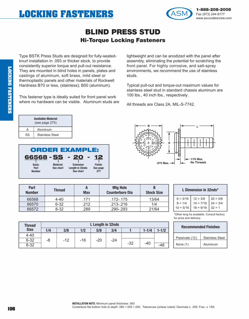
106
1-888-208-2008Fax (973) 244-9177www.accuratescrew.comLOCKING FASTENERS
BLIND PRESS STUDHi-Torque Locking Fasteners
Type BSTK Press Studs are designed for fully-seated-knurl installation in .093 or thicker stock, to provideconsistently superior torque and pull-out resistance.They are mounted in blind holes in panels, plates andcastings of aluminum, soft brass, mild steel orthermoplastic panels and other materials of RockwellHardness B70 or less, (stainless); B50 (aluminum).
This fastener type is ideally suited for front panel workwhere no hardware can be visible. Aluminum studs are
lightweight and can be anodized with the panel afterassembly, eliminating the potential for scratching thefront panel. For highly corrosive, and salt-sprayenvironments, we recommend the use of stainlessstuds.
Typical pull-out and torque-out maximum values forstainless steel stud in standard chassis aluminum are100 lbs., 40 inch lbs., respectively.
All threads are Class 2A, MIL-S-7742.
66568 4-40 .171 .172-.175 13/6466570 6-32 .212 .213-.216 1/466572 8-32 .289 .290-.293 21/64
PartNumber
ThreadA
MaxMtg Hole
Counterbore Dia B
Stock Size
1/4 3/8 1/2 5/8 3/4 1 1-1/4 1-1/24-406-32 -8 -12 -16 -20 -248-32 -32 -40 -48
ThreadSize
Passivate (12) Stainless Steel
None (1) Aluminum
Recommended Finishes
A Aluminum SS Stainless Steel
Available Material(see page 275)
INSTALLATION NOTE: Minimum panel thickness .093Conterbore flat bottom hole to depth .080 +.005 /-.000. Tolerances (unless noted): Decimals ± .005, Frac. ± 1/64.
*Other leng hs available. Consult factoryfor price and delivery.
ORDER EXAMPLE:66568
BasicPart
Number
SSMaterial:See chart
20Extension
Length in 32nds:See chart
12Finish:
See page277
---
6 = 3/168 = 1/4
10 = 5/16
12 = 3/814 = 7/1618 = 9/16
20 = 5/824 = 3/432 = 1
L Dimension in 32nds*
L Length in 32nds
LOC
KIN
G FA
ST
EN
ER
S
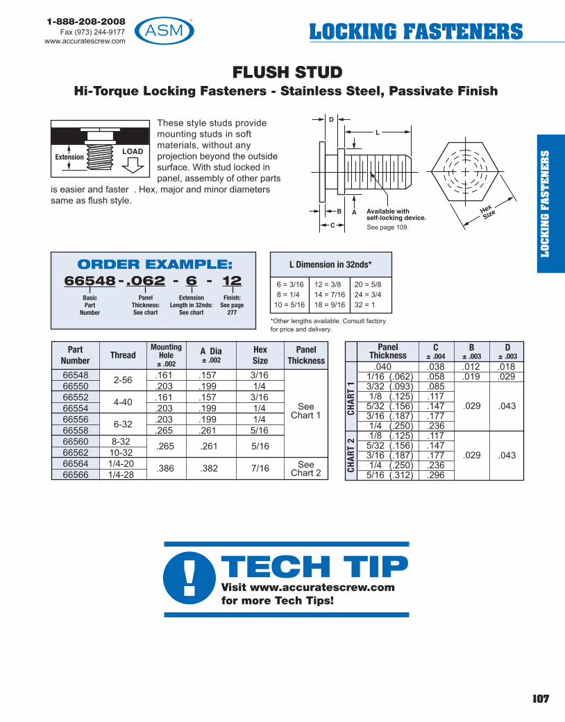
FLUSH STUDHi-Torque Locking Fasteners - Stainless Steel, Passivate Finish
66548 .161 .157 3/1666550 .203 .199 1/466552 .161 .157 3/1666554 .203 .199 1/466556 .203 .199 1/466558 .265 .261 5/1666560 8-3266562 10-3266564 1/4-2066566 1/4-28
See Chart 1
See Chart 2
PartNumber
Thread Mounting
Hole± .002
A Dia± .002
HexSize
PanelThickness
These style studs providemounting studs in softmaterials, without anyprojection beyond the outsidesurface. With stud locked inpanel, assembly of other parts
is easier and faster . Hex, major and minor diameterssame as flush style.
See page 109.
2-56
4-40
6-32
.265
.386
.261
.382
5/16
7/16
.040 .038 .012 .0181/16 (.062) .058 .019 .0293/32 (.093) .0851/8 (.125) .1175/32 (.156) .1473/16 (.187) .1771/4 (.250) .2361/8 (.125) .1175/32 (.156) .1473/16 (.187) .1771/4 (.250) .2365/16 (.312) .296
PanelThickness
CHA
RT 2
CHA
RT 1
.029
.029
.043
.043
*Other lengths available. Consult factoryfor price and delivery.
ORDER EXAMPLE:66548
BasicPart
Number
.062Panel
Thickness:See chart
6Extension
Length in 32nds:See chart
12Finish:
See page277
--- 6 = 3/168 = 1/4
10 = 5/16
12 = 3/814 = 7/1618 = 9/16
20 = 5/824 = 3/432 = 1
L Dimension in 32nds*
C± .004
B± .003
D± .003
107
1-888-208-2008Fax (973) 244-9177
www.accuratescrew.com LOCKING FASTENERS
LOC
KIN
G F
AS
TE
NE
RS
! TECH TIPVisit www.accuratescrew.comfor more Tech Tips!
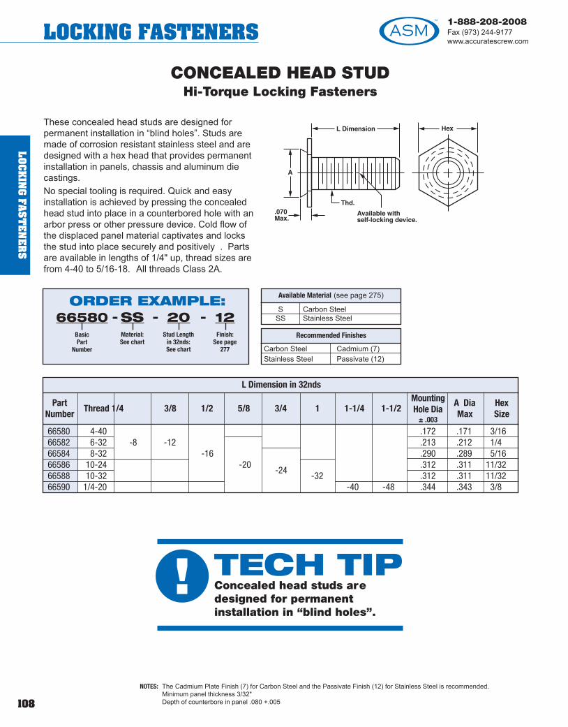
108
1-888-208-2008Fax (973) 244-9177www.accuratescrew.comLOCKING FASTENERS
66580 4-40 .172 .171 3/1666582 6-32 -8 -12 .213 .212 1/466584 8-32 -16 .290 .289 5/1666586 10-24 -20 .312 .311 11/3266588 10-32
-24-32 .312 .311 11/32
66590 1/4-20 -40 -48 .344 .343 3/8
CONCEALED HEAD STUDHi-Torque Locking Fasteners
These concealed head studs are designed forpermanent installation in “blind holes”. Studs aremade of corrosion resistant stainless steel and aredesigned with a hex head that provides permanentinstallation in panels, chassis and aluminum diecastings.No special tooling is required. Quick and easyinstallation is achieved by pressing the concealedhead stud into place in a counterbored hole with anarbor press or other pressure device. Cold flow ofthe displaced panel material captivates and locksthe stud into place securely and positively . Partsare available in lengths of 1/4" up, thread sizes arefrom 4-40 to 5/16-18. All threads Class 2A.
NOTES: The Cadmium Plate Finish (7) for Carbon Steel and the Passivate Finish (12) for Stainless Steel is recommended.Minimum panel thickness 3/32"Depth of counterbore in panel .080 +.005
Carbon Steel Cadmium (7)Stainless Steel Passivate (12)
Recommended Finishes
S Carbon Steel SS Stainless Steel
Available Material (see page 275)ORDER EXAMPLE:66580
BasicPart
Number
SSMaterial:See chart
20Stud Length
in 32nds:See chart
12Finish:
See page277
---
L Dimension in 32nds
PartNumber
Thread 1/4 3/8 1/2 5/8 3/4 1 1-1/4 1-1/2 MountingHole Dia
± .003
A DiaMax
Hex Size
LOC
KIN
G FA
ST
EN
ER
S
! TECH TIPConcealed head studs aredesigned for permanentinstallation in “blind holes”.
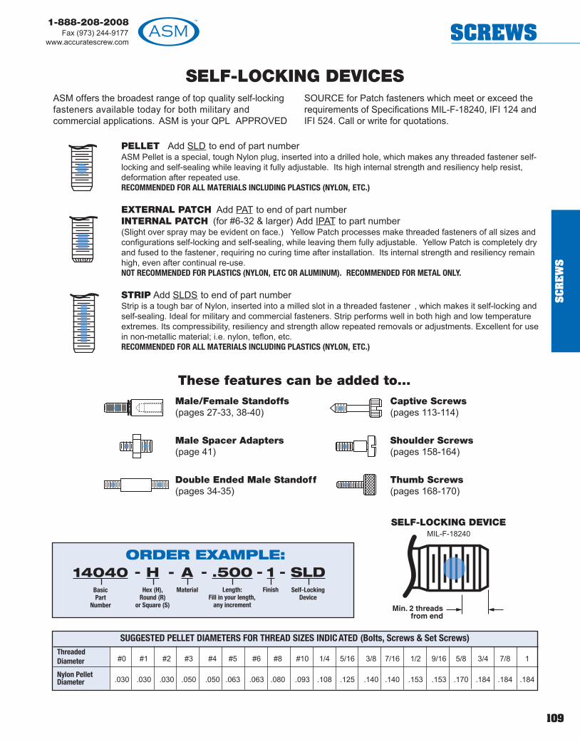
109
1-888-208-2008Fax (973) 244-9177
www.accuratescrew.com SCREWS
SC
RE
WS
SELF-LOCKING DEVICESASM offers the broadest range of top quality self-lockingfasteners available today for both military andcommercial applications. ASM is your QPL APPROVED
SOURCE for Patch fasteners which meet or exceed therequirements of Specifications MIL-F-18240, IFI 124 andIFI 524. Call or write for quotations.
PELLET Add SLD to end of part numberASM Pellet is a special, tough Nylon plug, inserted into a drilled hole, which makes any threaded fastener self-locking and self-sealing while leaving it fully adjustable. Its high internal strength and resiliency help resist,deformation after repeated use.RECOMMENDED FOR ALL MATERIALS INCLUDING PLASTICS (NYLON, ETC.)
EXTERNAL PATCH Add PAT to end of part numberINTERNAL PATCH (for #6-32 & larger) Add IPAT to part number(Slight over spray may be evident on face.) Yellow Patch processes make threaded fasteners of all sizes andconfigurations self-locking and self-sealing, while leaving them fully adjustable. Yellow Patch is completely dryand fused to the fastener, requiring no curing time after installation. Its internal strength and resiliency remainhigh, even after continual re-use. NOT RECOMMENDED FOR PLASTICS (NYLON, ETC OR ALUMINUM). RECOMMENDED FOR METAL ONLY.
STRIP Add SLDS to end of part numberStrip is a tough bar of Nylon, inserted into a milled slot in a threaded fastener , which makes it self-locking andself-sealing. Ideal for military and commercial fasteners. Strip performs well in both high and low temperatureextremes. Its compressibility, resiliency and strength allow repeated removals or adjustments. Excellent for usein non-metallic material; i.e. nylon, teflon, etc. RECOMMENDED FOR ALL MATERIALS INCLUDING PLASTICS (NYLON, ETC.)
SUGGESTED PELLET DIAMETERS FOR THREAD SIZES INDIC ATED (Bolts, Screws & Set Screws)Threaded Diameter #0 #1 #2 #3 #4 #5 #6 #8 #10 1/4 5/16 3/8 7/16 1/2 9/16 5/8 3/4 7/8 1
Nylon PelletDiameter .030 .030 .030 .050 .050 .063 .063 .080 .093 .108 .125 .140 .140 .153 .153 .170 .184 .184 .184
Male/Female Standoffs(pages 27-33, 38-40)
Male Spacer Adapters(page 41)
Double Ended Male Standoff(pages 34-35)
Captive Screws(pages 113-114)
Shoulder Screws(pages 158-164)
Thumb Screws(pages 168-170)
ORDER EXAMPLE:- - - - -14040
BasicPart
Number
HHex (H),
Round (R)or Square (S)
.500Length:
Fill in your length,any increment
AMaterial
1Finish
SLDSelf-Locking
Device
SELF-LOCKING DEVICEMIL-F-18240
These features can be added to...

1-888-208-2008Fax (973) 244-9177www.accuratescrew.comSCREWS
Front-MountRetainer Assembly
The LatestInnovation in
FastenerTechnology!
WHAT IS THE FMR2002?
• The FMR2002 is a new pa tented multi-purposefastener developed by ASM that is availableexternally/internally threaded for use as a retainerassembly (Fig. A) or threaded standoff (Fig. C) - plusit can be ordered without internal threads for use asa clear-hole standoff/spacer (Fig. B).
• The FMR2002 is completely installed from thefront of a panel due to its unique external threadeddesign – you simply drill, tap, and install with astandard socket or open ended wrench.
• The FMR2002 is produced hex-headed and isavailable in brass, steel, or stainless steel.
HOW DOES THE FMR2002SAVE TIME AND MONEY?
• Reduces Panel Assembly Time up to 20% due tothe unique completely front mount (or single-sided)installation process.
• Cuts Production Setup Costs because there is noneed for anvil/punch sets or equipment, such as anarbor press, punch press, or drill press.
• Eliminates Product Rejection Rates on bent,cracked, or bulging panels because, unlike traditionalswaged or flared products tha t require a pressingforce for installation, the FMR2002 simply screwstightly into place.
• Allows Onsite Product Repair due to its externalthreaded design and installation, which enables theFMR2002 to be easily removed and reused.
Call our Sales Department today a t 1-888-208-2008 forcomplete details.
Visit our Web site at www.accuratescrew.com to view avideo clip of the FMR2002’s easy front mount installa tion.
(Available assembly head style info. located on page 112)
Fig. A
Fig. C
Fig. B
110
SC
RE
WS

1-888-208-2008Fax (973) 244-9177
www.accuratescrew.com SCREWS
In Applications With Restricted Installation SpaceThe FMR2002 completely installs from the front (or asingle-side) of a panel using a standard socket or openended wrench (Fig. C). This dramatically reduces clearanceand accessibility constraints normally associa ted withtraditional retainer/standoff products that require installationusing a press, anvil, or punch (Fig. D).
In Applications With Panel Edge Distortion ConcernsThe FMR2002 can be installed much c loser to the edge of apanel (Fig. E) than a traditional retainer/standoff withoutconcerns about panel distortion. This is possible becausethe shank portion of the FMR2002 is screwed in ra ther thanpressed, which lessens the force and stress a pplied to thepanel material, eliminating any bulging or cracking issues(Fig. F).
THE FMR2002 IS A PERFECT CHOICEFOR USE IN PCB APPLICATIONS!See Fig. G
The FMR2002 is an excellent alternative to existing flared and swage standoff products…
PC Board
Fig. C Fig. D
Fig. GFig.E
For FMR2002 standoff information please refer to the product section starting on pa ge 7.
Fig.F
111
SC
RE
WS
Front-MountRetainer Assembly

112
1-888-208-2008Fax (973) 244-9177www.accuratescrew.comSCREWS
SC
RE
WS
Front-MountRetainer Assembly
FRONT-MOUNT PAN HEAD, SLOTTED or PHILLIPS. See page 117.
FRONT-MOUNT BINDING HEAD SCREW,SLOTTED ONLY. See page 120.
FRONT-MOUNT FILLISTER HEAD SCREW,SLOTTED or PHILLIPS. See page 123.
FRONT-MOUNT ROUND HEAD SCREW,SLOTTED or PHILLIPS. See page 126.
FRONT-MOUNT SOCKET HEAD CAP SCREWSee page 129.
FRONT-MOUNT HEX HEAD SCREWSee page 132.
FRONT-MOUNT HEX SOCKET LOW HEAD SCREW. See page 139.
FRONT-MOUNT HEX SOCKET BUTTON HEAD SCREW. See page 141.
FRONT-MOUNT 6-LOBE SOCKET BUTTON HEAD SCREW. See page 144.
The NEW FMR2002 is available in aluminum, brass, steel and stainless steel in the screw styles shown below .Refer to these pages for screw dimensions.
AVAILABLE SCREW STYLES
2-56 .062 8-32 3/164-40 .093 10-32 1/46-32 .093 1/4-28 5/168-32 .093 1/4-28 5/1610-32 .093 5/16-24 3/810-24 .093 5/16-24 3/81/4-20 .125 3/8-24 7/16
TCaptive
Screw ThreadP M S
HexASSEMBLY INSTALLED
See page 157 forLock Washers
U .125V .187W .250X .312Y .375Z .500
ShankCode
R± .003
ORDER EXAMPLE:- - -114050
Basic PartNumber:
See styles belowfor page number
PSPan Head
Slotted (PS) orPhillips (PP)
.500Length
UShank Code:
See chartbelow
SSMaterial:See chart
above
12Finish:
See page277
- -
A AluminumB BrassS Steel SS Stainless Steel
Available Material (see page 275)

A AluminumB BrassS Steel
SS Stainless Steel
Available Material (see page 275)
CAPTIVE PANEL SCREWSFor Retainers and Split Washers, see pages 190-197.
BasicPartNo.
ThreadL ± .015
Increments of 1/16
H Dia+.015-.005
G Lgth± 1/64
C+.005-.000
FRef.
B± .005
A± .010 Teeth
per inchDiametrical
Pitch
Chamfer45°
Max.
E+.010-.000
D+.000-.015
J+.000-.016
Knurl
700 4-40 UNC-2A .375 to 1.0 5/16 x 5/16 .047 .078 .125 5/64 .078 – .078 40.7 128 .022702 6-32 UNC-2A .500 to 2.0 5/16 x 5/16 .047 .078 .212 3/32 .095 – .095 40.7 128 .022704 8-32 UNC-2A .500 to 2.0 5/16 x 5/16 .047 .078 .212 3/32 .120 – .120 40.7 128 .022706 10-24 UNC-2A .625 to 2.0 3/8 x 7/16 .063 .094 .250 5/32 .130 – .130 30.6 96 .030708 10-32 UNF-2A .625 to 2.0 3/8 x 7/16 .063 .094 .250 5/32 .130 – .130 30.6 96 .030710 1/4-20 UNC-2A .750 to 3.0 1/2 x 9/16 .078 .094 .313 3/16 .175 – .175 30.6 96 .038712 1/4-28 UNF-2A .750 to 3.0 1/2 x 9/16 .078 .094 .313 3/16 .175 – .175 30.6 96 .038714 5/16-18 UNC-2A 1.000 to 3.0 5/8 x 11/16 .094 .125 .375 1/4 .230 – .230 20.4 64 .041716 5/16-24 UNF-2A 1.000 to 3.0 5/8 x 11/16 .094 .125 .375 1/4 .230 – .230 20.4 64 .041717 3/8-16 UNC-2A 1.000 to 3.0 5/8 x 11/16 .094 .125 .375 1/4 .280 – .280 20.4 64 .041
718 4-40 UNC-2A .375 to 2.0 5/16 x 3/16 .031-.041 .063 9/32 .078 – 40720 6-32 UNC-2A .375 to 2.0 5/16 x 3/16 .040-.050 .063 9/32 .095 – 40722 6-32 UNC-2A .375 to 2.0 3/8 x 3/16 .040-.050 .063 9/32 .095 – 40724 8-32 UNC-2A .625 to 2.0 7/16 x 1/4 .063 .063 3/8 .120 – 40726 10-24 UNC-2A .625 to 3.0 7/16 x 1/4 .063 .063 3/8 .130 – 30728 10-32 UNF-2A .625 to 3.0 7/16 x 1/4 .063 .063 3/8 .130 – 30730 12-24 UNC-2A .625 to 3.0 9/16 x 1/4 .063 .094 3/8 .152 – 30732 1/4-20 UNC-2A .625 to 3.0 9/16 x 1/4 .063 .094 3/8 .175 – 30734 1/4-20 UNC-2A .625 to 3.0 3/4 x 1/4 .063 .125 3/8 .175 – 30736 1/4-28 UNF-2A .625 to 3.0 9/16 x 1/4 .063 .094 3/8 .175 – 30738 1/4-28 UNF-2A .625 to 3.0 3/4 x 1/4 .063 .125 3/8 .175 – 30740 5/16-24 UNF-2A .625 to 3.0 9/16 x 1/4 .063 .094 3/8 .235 – 30
BasicPartNo.
ThreadL ± .015
Increments of 1/16
H Dia+.015–.005
G Lngth± 1/64
C+.005–.000
B
± .005
A
± .010
E+.010–.000
D
± 1/64
KnurlPitch
ORDER EXAMPLE:- - -702
BasicPart
Number
1.500Length
SSMaterial:See chart
12Finish:
See page 277
NS suffix indicates No Slot. EXAMPLE: 702-1.500-SS-12-NS
Optional self-locking deviceavailable. Add SLD to end of partnumber (see page 109).
113
1-888-208-2008Fax (973) 244-9177
www.accuratescrew.com SCREWS
SC
RE
WS

114
1-888-208-2008Fax (973) 244-9177www.accuratescrew.comSCREWS
SC
RE
WS
CAPTIVE PANEL SCREWSFor Retainers & Split Washers, see pages 190-197.
745 4-40 UNC-2A .375 to 2.0 5/16 x 1/8 .047 .078 3/16 1/8 .078 – .078 13/64 1/16 40747 6-32 UNC-2A .500 to 2.0 5/16 x 1/8 .047 .078 3/16 1/8 .095 – .095 13/64 1/16 40
BasicPartNo.
ThreadL ± .015
Incrementsof 1/16
A AluminumB BrassS Steel
SS Stainless Steel
Available Material (see page 275)
ORDER EXAMPLE:- - -745
BasicPart
Number
1.500Length
SSMaterial:See chart
12Finish:
See page 277
NS suffix indicates No Slot. EXAMPLE: 745-1.500-SS-12-NS
Optional self-locking deviceavailable. Add SLD to end of partnumber (see page 109).
C+.005-.000
E+.010-.000
D+.010-.005
FRef.
B± .005
A± .010
J+.000-.016
M± .010
N± .010
KnurlPitch
H Dia+.015-.005
GLngth± .1/64
749 8-32 UNC-2A .625 to 2.0 1/2 x 3/16 .063 .078 1/4 1/8 .120 – .120 13/32 1/16 40751 8-32 UNC-2A .625 to 2.0 5/8 x 3/16 .063 .078 1/4 1/8 .120 – .120 1/2 1/16 40752 10-24 UNC-2A .625 to 3.0 1/2 x 3/16 .063 .094 1/4 1/8 .130 – .130 13/32 1/16 30753 10-32 UNF-2A .625 to 3.0 1/2 x 3/16 .063 .094 1/4 1/8 .130 – .130 13/32 1/16 30755 10-32 UNF-2A .625 to 3.0 5/8 x 3/16 .063 .094 1/4 1/8 .130 – .130 1/2 1/16 30757 12-24 UNC-2A .625 to 3.0 5/8 x 3/16 .078 .094 1/4 1/8 .152 – .152 1/2 1/16 30759 1/4-20 UNC-2A .625 to 3.0 5/8 x 3/16 .078 .094 3/8 1/4 .175 – .175 1/2 1/16 30761 1/4-20 UNC-2A .750 to 3.0 3/4 x 1/4 .078 .094 3/8 1/4 .175 – .175 1/2 1/8 30
BasicPartNo.
ThreadL ± .015
Incrementsof 1/16
C+.005-.000
E+.010-.000
D+.010-.005
FRef.
B± .005
A± .010
J+.000-.016
M± .010
N± .010
KnurlPitch
H Dia+.015-.005
GLngth± .1/64
! TECH TIPASM can manufacture knurled captive panelscrews with six lobe and hex drive featur es.

115
1-888-208-2008Fax (973) 244-9177
www.accuratescrew.com SCREWS
SC
RE
WS
CAPTIVE SCREWSRetainers & Split Washers, see pages 190-197.
BasicPartNo.
Thread L ± .015Increments
of 1/16
765 4-40 UNC-2A .375 to 2.0 .225 .207 .195 .104 .084 .039 .031 .059 .049 3/16 .096 .078 .067767 6-32 UNC-2A .500 to 2.0 .279 .257 .244 .128 .105 .048 .039 .074 .060 1/4 .121 .095 .083769 8-32 UNC-2A .500 to 2.0 .332 .308 .292 .152 .126 .054 .045 .088 .072 1/4 .142 .120 .100771 10-24 UNC-2A .625 to 3.0 .385 .359 .340 .176 .148 .060 .050 .103 .084 1/4 .164 .130 .116773 10-32 UNF-2A .625 to 3.0 .385 .359 .340 .176 .148 .060 .050 .103 .084 1/4 .164 .130 .116
HDMax Min Abs
Sharp Sharp Min
G
MinMax
C
MinMax
E
MinMax
D± .010
F± .005
B± .005
P+.020-.000
A AluminumB BrassS Steel
SS Stainless Steel
Available Material(see page 275)
Captive PanelScrew Assembly
Panel Washer See top of page 243 for details.
775 2-56 UNC-2A .250 to 2.0 .140 .124 .083 .066 .031 .023 .037 .025 1/8 .061 .062 .053777 3-48 UNC-2A .250 to 2.0 .161 .145 .095 .077 .035 .027 .043 .030 1/8 .070 .070 .161779 4-40 UNC-2A .312 to 2.0 .183 .166 .107 .088 .039 .031 .048 .035 5/32 .078 .079 .069781 4-48 UNF-2A .312 to 2.0 .183 .166 .107 .088 .039 .031 .048 .035 5/32 .078 .079 .069783 6-32 UNC-2A .375 to 3.0 .226 .208 .132 .111 .048 .039 .060 .045 3/16 .095 .096 .086785 6-40 UNF-2A .375 to 3.0 .226 .208 .132 .111 .048 .039 .060 .045 3/16 .095 .096 .086787 8-32 UNC-2A .500 to 3.0 .270 .250 .156 .133 .054 .045 .071 .054 3/16 .120 .113 .102789 10-24 UNC-2A .625 to 3.0 .313 .292 .180 .156 .060 .050 .083 .064 1/4 .130 .130 .118791 10-32 UNF-2A .625 to 3.0 .313 .292 .180 .156 .060 .050 .083 .064 1/4 .130 .130 .118
BasicPartNo.
ThreadL ± .015
Incrementsof 1/16
HD G
MinMax
C
MinMax
E
MinMax
D± .010
B± .005
P
MinMaxMinMax
CAPTIVE PANEL SCREW ASSEMBLYORDER EXAMPLE:
771BasicPart
Number
1.500Length
SSMaterial:See chart
AAssembly with Panel
Washer
12Finish:
See page277
----
ORDER EXAMPLE:- - -771
BasicPart
Number
1.500Length
SSMaterial:See chart
12Finish:
See page 277
NS suffix indicates No Slot. EXAMPLE: 765-.375-SS-12-NS No SlotOptional self-locking device available. Add SLD to end of part number(see page 109).

116
1-888-208-2008Fax (973) 244-9177www.accuratescrew.comSCREWS
CAPTIVE SCREWS - LOCK ASSEMBLYAvailable For All Captive Panel Screws
In Any Head Styles and Thread Sizes – In Steel or Stainless Steel
Spring Steel Screws:Heat Treated Spring Steel QQ-S-700/ASTM A 684
Stainless Steel Screws:Stainless Steel - Type 301-304
2-56 .078 .150 .008 .028 24007 2274-40 .097 .203 .010 .030 24023 2276-32 .119 .200 .005 .030 24043 2278-32 .156 .312 .025 .040 24087 (ID .156) 22810-32 .173 .365 .015 .035 24105 2281/4-20 .234 .562 .030 .050 24165 (ID .234) 2293/8-16 .334 .620 .015 .080 24231 229
Thread BID
AOD
CThickness
DHeight
Belleville Washer #
See Page
Belleville Washer Selection DataSupplied assembled • Availability is from stock - 2 weeks
NOTE: Standard fastener products having a class 2A thread, once plated, may not exit GO GAGE.Thread UNC-3A (except 10-32 UNF-3A) R =.030 Max.
ORDER EXAMPLE:114070
BasicPart
Number
FSFillister Head
Slotted (FS) orPhillips (FP)
.500Length:
L
SSMaterial:See chart
BWBellevilleWasher
----
Select captive screws from pages 117-156.
Add BW to end of part number.
For Stainless Steel Screws:EXAMPLE: 114070-FS-.500-SS-BW-12
For Steel Screws:EXAMPLE: 114070-FS-.500-S-BW-7
12Finish:
See page277
-
Stainless Steel Belleville Washer
Heat-treated Spring Steel Belleville Washer
S Spring Steel SS Stainless Steel
Available Material (see page 275)
Belleville Washer Specs
SC
RE
WS
! TECH TIPMost of our fasteners are made from 300 series stainless steel which is non-magnetic and can not be heat tr eated.

SCREWS
PAN HEAD CAPTIVE PANEL SCREWS - Slotted or PhillipsFor Captive Panel Screw assemblies, see below and page 1 18.
*2-56 114050 .181 .155 .053 .045 062 .053 .031 .022 .031 .023 .104 091 .059 .041 .017 1/8 .061 .250 - .750 .174-40 114052 .238 .205 .068 .058 080 .070 .040 .030 .039 .031 .122 .109 .078 .060 .019 5/32 .078 .312 - 1.00 226-32 114054 .294 .256 .082 .072 097 .087 .050 .037 .048 .039 .166 .153 .091 .066 .028 3/16 .095 .375 - 1.00 268-32 114056 .347 .306 .096 .085 .115 .105 .058 .045 .054 .045 .182 .169 .108 .082 .030 3/16 .120 .375 - 1.00 2810-24 114059 .403 .357 .110 .099 .133 .122 .068 .053 .060 .050 .199 .186 .124 .100 .031 1/4 .130 .500 - 1.25 3610-32 114058 .403 .357 .110 .099 .133 .122 .068 .053 .060 .050 .199 .186 .124 .100 .031 1/4 .130 .500 - 1.25 361/4-20 114051 .517 .473 .144 .130 .175 .162 .087 .070 .075 .064 .281 268 .161 .135 .036 1/4 .175 .500 - 3.00 39
ThreadBasicPart
Number MaxMax Min Min Max Min Max Min Max Min Max Min Max Min Min
K±.010
AHead Dia
Height of Head
BSlotted
B1
Recessed
CSlot Depth
JSlot Width
EDiameter
TDepth
NWidth
Dimension of RecessG
±.005L* PK
Ref.Only
Slotted Head (PS) Phillips Head (PP) Lead Point Option
*Not available with O-ring. For L tolerance, see page 281. Increments of 1/16" is recommended, however , any length may be specif ied.
2-56 .185 .188 .188 1/4 .062 FA-2 FP-24-40 .231 .234 .234 5/16 .093 FA-4 FP-46-32 .231 .234 .234 3/8 .093 FA-6 FP-68-32 .231 .234 .234 1/2 .093 FA-8 FP-810-32 .231 .234 .234 1/2 .093 FA-10 FP-101/4-20 .309 .312 .312 9/16 .125 FA-25 FP-25
Shank Board R1
Code Thickness ± .003
A 1/32 .027B 1/16 .060C 3/32 .104D 1/8 .144E 3/16 .221F 1/4 .301
B Brass, composition 360
S Steel, low carbon 1018 ASTM 108SS Stainless Steel, 18-8, 302-304 series
Available Material (see page 275)
PAN HEAD CAPTIVE PANEL SCREW ASSEMBLYSlotted or Phillips
Thread M Dia
Min Max
MountingHole Dia+.003 -.000
SDia
PTooling
Anvil PunchB Brass, composition 360S Steel, low carbon 1018
ASTM 108 SS Stainless Steel 18-8,
302-304 series,ASTMA 580/A580M-98
Available Material(see page 275)
Flare Tool supplied by ASM. Countersink82° by approximately 1/2 board thickness.
Slotted PhillipsEasy One Step Installation Procedure
NOTE: R =.030 Max.
ORDER EXAMPLE:114050
BasicPart
Number
PSPan Head
Slotted (PS) orPan Head Phillips (PP)
.500Length:
L
SSMaterial:See chart
--- 12Finish:
See page277
-
To add the Lead Point option, add prefix P to part number. EXAMPLE: P1114050-PS-.500-SS-12
ORDER EXAMPLE:114050
BasicPart
Number
PSPan Head
Slotted (PS) orPan Head Phillips (PP)
.500Length:
L
SSMaterial:See chart
--- 12Finish:
See page277
-BShank Code:
See chart
-
ALSO AVAILABLE AS AN FMR2002 ASSEMBLY(see pages 110-112 for more information)
Order Example:114050-PS-.500-U-SS-12
NOTE: Standard fastener products having a class 2A thread, once plated, may not exit GO GAGE.Thread UNC-3A (except 10-32 UNF-3A) R =.030 Max. 117
1-888-208-2008Fax (973) 244-9177
www.accuratescrew.com
SC
RE
WS

SCREWS
Brass Captive Screw Assembly (B) will befurnished with silicone bronze split lockwashers conforming to ASTM B99, copperalloy no. 651 or no. 655. Internal and externalPhosphor Bronze lock washers conforming toASM B159, copper alloy no. 510. Brass flatwashers will be no. 260.
Stainless Steel Captive Screw Assembly (SS) willbe furnished with stainless steel flat washersconforming to AISI type 302 or 305 and lockwashers of stainless steel type 18-8.
Steel Captive Screw Assembly (S) will befurnished with steel flat washers of low carbonsteel 1006-1010 soft and steel lock washerconforming to ASTM A366.
External Tooth Lock Washer (J)See page 157 for details.
PAN HEAD CAPTIVE PANEL SCREW ASSEMBLY
PAN HEAD PANEL SCREW ASSEMBLY - FULL THREAD
Split Lock Washer (G)See page 157 for details.
Internal Tooth Lock Washer (H)See page 157 for details.
Screw Outside Dia T* ± .005Size ± .010 Thickness
2 .187 .0204 .255 .0306 .312 .0308 .312 .03010 .375 .0301/4 .500 .045**
MATERIAL CHART
Captive Washer Specifications
Belleville Washer see page 116.
See page 117 for screw dimensions.
Split Lock Washer (GF)See page 157 for details
Internal Tooth Lock Washer (HF)See page 157 for details
External Tooth Lock Washer (JF)See page 157 for details
NOTE: Standard fastener products having a class 2A thread, once plated, may not exit GO GAGE.Thread UNC-3A (except 10-32 UNF-3A) R =.030 Max.
* Fully threaded up tothe flat washer.
** Maximum length1.50 inches.
ORDER EXAMPLE:114050
PartNumber:
See page 117
PSPan Head
Slotted (PS) orPhillips (PP)
.250Length:
L
GAssemblyw/Split (G)L’Washer &Flat Washer
--- 12Finish:
See page277
-SSMaterial:
See page 117
-ORDER EXAMPLE:
114050Part
Number:See page 117
PSPan Head
Slotted (PS) orPhillips (PP)
.250Length:
L
HAssembly
w/Internal (H)L’Washer &Flat Washer
--- 12Finish:
See page277
-SSMaterial:
See page 117
-
ORDER EXAMPLE:114050
PartNumber:
See page 117
PSPan Head
Slotted (PS) orPhillips (PP)
.250Length:
L
JAssembly
w/External (J)L’Washer &Flat Washer
--- 12Finish:
See page277
-SSMaterial:
See page 117
-
ORDER EXAMPLE:114050
PartNumber:
See page 117
PSPan Head
Slotted (PS) orPhillips (PP)
.250Length:
L
GFAssembly
w/Split (GF),Internal (HF) or
External (JF)
--- 12Finish:
See page277
-SSMaterial:
See page 117
-
118
1-888-208-2008Fax (973) 244-9177www.accuratescrew.com
SC
RE
WS

119
1-888-208-2008Fax (973) 244-9177
www.accuratescrew.com SCREWS
SELF-SEALING WASHERSMaterial: #60 Medium Durameter Neoprene
For Metric style, see page 147.
Pan Head Captive Panel ScrewSlotted or Phillips
Pan Head Full Thread Panel ScrewSlotted or Phillips
SELF-SEALING ASSEMBLYPan Head Captive Panel Screw - Slotted or Phillips
For Metric Style, see page 147.
SELF-SEALING FULL THREADPhillips Pan Head with Integral Silicone O-Ring
Self-Sealing Washers Material: #60 Medium Durameter Neoprene
For L tolerance, see page 281. Increments of 1/16" is recommended, however , any leng h may be specified. Cost difference is negligible, additional delivery time approximately 1-1/2 weeks.
For L tolerance, see page 281. Increments of 1/16" is recommended, however , any length may bespecified. Cost difference is negligible, additional delivery time approximately 1-1/2 weeks.
NOTE: Standard fastener products having a class 2A thread, once plated, may not exit GO GAGE.Thread UNC-3A (except 10-32 UNF-3A) R =.030 Max.
ORDER EXAMPLE:S
Self-Sealing
114050Basic Screw
PartNumber
PSPan Head
Slotted (PS) orPhillips (PP)
SSMaterial:See page
117
--- 12Finish:
See page277
-.500Length:
L
-
Any one dimension change, add to part number .EXAMPLE: S-114050-PS-.500-SS-F-12 (K=3/16)
ORDER EXAMPLE:S
Self-Sealing
114050Basic Screw
PartNumber
PSPan Head
Slotted (PS) orPhillips (PP)
SSMaterial:See page
117
--- 12Finish:
See page277
-.500Length:
L
- FFull
Thread
-
ORDER EXAMPLE:114050
Basic ScrewPart
Number
PSPan Head
Slotted (PS) orPhillips (PP)
.500Length:
L
SSelf-Sealing
-- 12Finish:
See page277
- SSMaterial:See page
117
-BShank Code:See chart on
page 116
- -
Any one dimension change add to part number . EXAMPLE: S-114050-PS-.500-B-SS-F-12 (K=3/16)
Slotted
Phillips
ORDER EXAMPLE:114052
Basic ScrewPart
Number
PPPan Head
Phillips (PP)
.250Length:
L
SRSelf-Sealingwith Integral
Silicone O-Ring
-- 12Finish:
See page277
- SSMaterial:See page
117
--
SC
RE
WS

120
1-888-208-2008Fax (973) 244-9177www.accuratescrew.comSCREWS
SC
RE
WS
BINDING HEAD PANEL SCREW ASSEMBLY- FULL THREADSplit Lock Washer (GF)
See page 157 for details.External Tooth Lock Washer (JF)
See page 157 for details.Internal Tooth Lock Washer (HF)
See page 157 for details.
See page 157 for detailson split, internal andexternal tooth washers.
* Fully threaded up to theflat washer.
** Maximum length 1.50inches.
ORDER EXAMPLE:114060
PartNumber:
See page 120
BSBinding HeadSlotted (BS)
.500Length:
L
GFAssembly
w/Split (GF),Internal (HF) or
External (JF)
--- 12Finish:
See page277
-SSMaterial:
See page 120
-
BINDING HEAD CAPTIVE SCREWSlotted Only
For Binding Head Captive Screw assembly, see pages 121-122. For Retainer Washers, see page 147.
ThreadBasicPart
Number MaxMax Min Min Max Min
K± .010
AHead Dia
B Head Height
C Head Oval Height
Slotted Head (BS)
2-56 114060 .181 .171 .050 .043 .018 .013 .030 .020 .031 .023 1/8 .061 .250 - .750 .174-40 114062 .235 .223 .068 .061 .025 .018 .042 .030 .039 .031 5/32 .078 .312 - 1.00 .226-32 114064 .290 .275 .087 .078 .032 .024 .053 .040 .048 .039 3/16 .095 .375 - 1.00 .268-32 114066 .344 .326 .105 .095 .039 .029 .065 .050 .054 .045 3/16 .120 .375 - 1.00 .2810-24 114069 .399 .378 .123 .112 .045 .034 .077 .060 .060 .050 1/4 .130 .500 - 1.25 .3610-32 114068 .399 .378 .123 .112 .045 .034 .077 .060 .060 .050 1/4 .130 .500 - 1.25 .361/4-20 114061 .525 .498 .165 .152 .061 .046 .105 .084 .075 .064 1/4 .175 .500 - 3.00 .39
G± .005
L* PKRef.OnlyMax Min
DSlot Depth
Max Min
JSlot Width
*For L tolerance, see page 281. Increments of 1/16" is recommended, however , any length may be specified. Cost dif ference is negligible, addi ional delivery timeapproximately 1-1/2 weeks.
SlottedHeadOrderingCode: BS
B Brass, composition 360
S Steel, low carbon 1018 ASTM 108
SS Stainless Steel, 18-8, 302-304 series
Available Material (see page 275)
Lead Point Option
NOTE: Standard fastener products having a class 2A thread, once plated, may not exit GO GAGE.Thread UNC-3A (except 10-32 UNF-3A) R =.030 Max.
ORDER EXAMPLE:
To add the Lead Point Option, add prefix P to part number.EXAMPLE: P114060-BS-.500-SS-12
- - -114060BasicPart
Number
BSBinding
HeadSlotted (BS)
.500Length:
L
SSMaterial:See chart
12Finish:
See page277
-
ALSO AVAILABLE AS ANFMR2002 ASSEMBLY
(see pages 110-112 for more information)
Order Example:114060-BS-.500-U-SS-12

121
1-888-208-2008Fax (973) 244-9177
www.accuratescrew.com SCREWS
SC
RE
WS
BINDING HEAD CAPTIVE PANEL SCREW ASSEMBLY
External Tooth Lock Washer (J)See page 157 for details.
BINDING HEAD PANEL SCREW ASSEMBLY- FULL THREAD
Split Lock Washer (G)See page 157 for details.
Internal Tooth Lock Washer (H)See page 157 for details.
Split Lock Washer (GF)See page 157 for details.
External Tooth Lock Washer (JF)See page 157 for details.
Internal Tooth Lock Washer (HF)See page 157 for details.
Screw Outside Dia T* ± .005Size ± .010 Thickness
2 .187 .0204 .255 .0306 .312 .0308 .375 .03010 .500 .0301/4 .562 .045**
Captive Washer Specifications
Belleville Washer see page 116.
See page 120 for screw dimensions.
See page 157 for detailson split, internal andexternal tooth washers.
* Fully threaded up to theflat washer.
** Maximum length 1.50inches.
NOTE: Standard fastener products having a class 2A thread, once plated, may not exit GO GAGE.Thread UNC-3A (except 10-32 UNF-3A) R =.030 Max.
B Brass, composition 360S Steel, low carbon 1018 ASTM 108
SS Stainless Steel 18-8, 302-304 series
Available Material (see page 275)
ORDER EXAMPLE:G
Assemblyw/Split (G)L’Washer & Flat Washer
114060Part
Number:See page 120
BSBinding HeadSlotted (BS)
SSMaterial:See page
120
-- - 12Finish:
See page277
-.500Length:
L
-ORDER EXAMPLE:
HAssembly
w/Internal (H)L’Washer & Flat Washer
114060Part
Number:See page 120
BSBinding HeadSlotted (BS)
SSMaterial:See page
120
-- - 12Finish:
See page277
-.500Length:
L
-
ORDER EXAMPLE:J
Assemblyw/External (J)
L’Washer & Flat Washer
114060Part
Number:See page 120
BSBinding HeadSlotted (BS)
SSMaterial:See page
120
-- - 12Finish:
See page277
-.500Length:
L
-
ORDER EXAMPLE:114060
PartNumber:
See page 120
BSBinding HeadSlotted (BS)
.500Length:
L
GFAssembly
w/Split (GF),Internal (HF) or
External (JF)
--- 12Finish:
See page277
-SSMaterial:
See page 120
-

122
1-888-208-2008Fax (973) 244-9177www.accuratescrew.comSCREWS
SC
RE
WS
2-56 114060 .181 .171 .050 .043 .018 .013 .030 .020 .031 .023 1/8 .061 .250 - .7504-40 114062 .235 .223 .068 .061 .025 .018 .042 .030 .039 .031 5/32 .078 .312 - 1.006-32 114064 .290 .275 .087 .078 .032 .024 .053 .040 .048 .039 3/16 .095 .375 - 1.008-32 114066 .344 .326 .105 .095 .039 .029 .065 .050 .054 .045 3/16 .120 .375 - 1.0010-24 114069 .399 .378 .123 .112 .045 .034 .077 .060 .060 .050 1/4 .130 .500 - 1.2510-32 114068 .399 .378 .123 .112 .045 .034 .077 .060 .060 .050 1/4 .130 .500 - 1.251/4-20 114061 .525 .498 .165 .152 .061 .046 .105 .084 .075 .064 1/4 .175 .500 - 3.00
BINDING HEAD CAPTIVE PANEL SCREW ASSEMBLYSlotted Only
For split lock washers, see page 157.
ThreadBasicPart
Number
K± .010
G± .005
L*Length
2-56 .185 .188 .188 1/4 .062 FA-2 FP-24-40 .231 .234 .234 5/16 .093 FA-4 FP-46-32 .231 .234 .234 3/8 .093 FA-6 FP-68-32 .231 .234 .234 1/2 .093 FA-8 FP-810-32 .231 .234 .234 1/2 .093 FA-10 FP-101/4-20 .309 .312 .312 9/16 .125 FA-25 FP-25
Shank Board R1
Code Thickness ± .003
A 1/32 .027B 1/16 .060C 3/32 .104D 1/8 .144E 3/16 .221F 1/4 .301
Thread M Dia
Min Max
MountingHole Dia+.003 -.000
SDia
P Tooling
Anvil Punch
Easy One Step Installation ProcedureFlare Tool supplied by ASM countersink 82°
by approximately 1/2 board thickness.
B Brass, composition 360S Steel, low carbon 1018 ASTM 108
SS Stainless Steel 18-8, 302-304 series
Available Material (see page 275)
See Below
Retainer and Flare Tooling Data
*For L tolerance, see page 281. Increments of 1/16" is recommended, however , any length may be specified.
NOTE: Standard fastener products having a class 2A thread, once plated, may not exit GO GAGE.Thread UNC-3A (except 10-32 UNF-3A) R =.030 Max.
ORDER EXAMPLE:114060
BasicPart
Number
BSBinding HeadSlotted (BS)
.500Length:
L
SSMaterial:See chart
--- 12Finish:
See page277
-BShank Code:
See chart
-
AHead Dia
B Head Height
C Head Oval Height
DSlot Depth
JSlot Width
Max Min Max Min Max Min Max Min Max Min
! TECH TIPMetric sizes and threadsavailable on many differentproducts we manufacture.
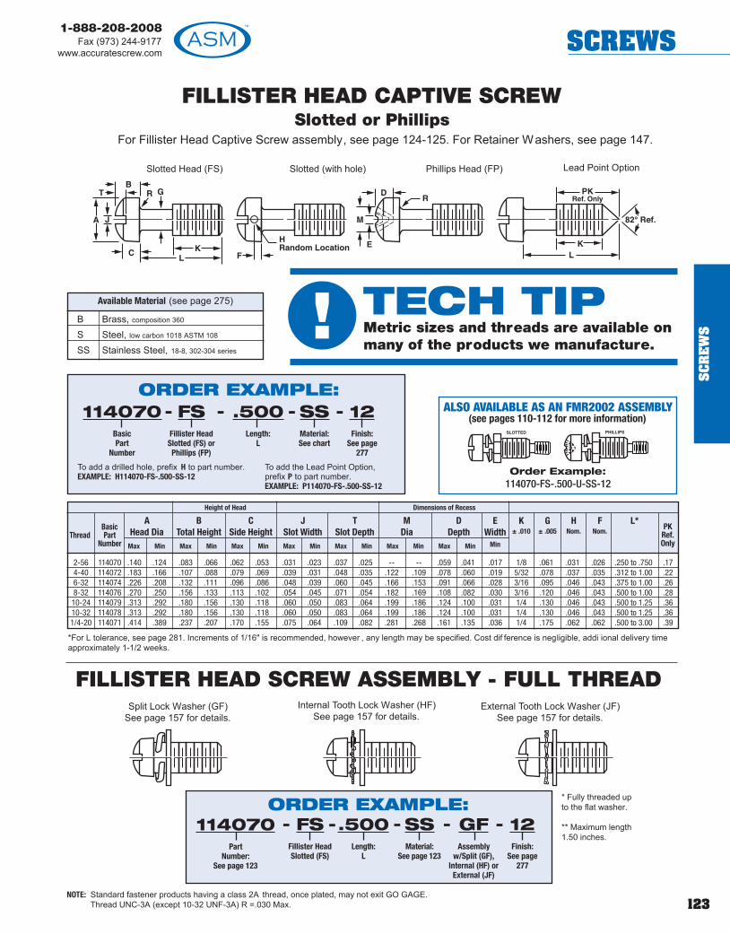
123
1-888-208-2008Fax (973) 244-9177
www.accuratescrew.com SCREWS
SC
RE
WS
FILLISTER HEAD CAPTIVE SCREWSlotted or Phillips
For Fillister Head Captive Screw assembly, see page 124-125. For Retainer Washers, see page 147.
Slotted Head (FS) Lead Point OptionPhillips Head (FP)Slotted (with hole)
*For L tolerance, see page 281. Increments of 1/16" is recommended, however , any length may be specified. Cost dif ference is negligible, addi ional delivery timeapproximately 1-1/2 weeks.
B Brass, composition 360
S Steel, low carbon 1018 ASTM 108
SS Stainless Steel, 18-8, 302-304 series
Available Material (see page 275)
ORDER EXAMPLE:- - -114070
BasicPart
Number
FSFillister Head
Slotted (FS) orPhillips (FP)
.500Length:
L
SSMaterial:See chart
12Finish:
See page277
-
To add a drilled hole, prefix H to part number. EXAMPLE: H114070-FS-.500-SS-12
To add the Lead Point Option, prefix P to part number. EXAMPLE: P114070-FS-.500-SS-12
Max Min Max Min Max Min Max Min Max Min Max Min Max Min
AHead Dia
BTotal Height
CSide Height
JSlot Width
TSlot Depth
MDia
DDepth
EWidth
Min
K± .010
G± .005
HNom.
FNom.
L*PKRef.Only
ThreadBasicPart
Number
Height of Head Dimensions of Recess
2-56 114070 .140 .124 .083 .066 .062 .053 .031 .023 .037 .025 -- -- .059 .041 .017 1/8 .061 .031 .026 .250 to .750 .174-40 114072 .183 .166 .107 .088 .079 .069 .039 .031 .048 .035 .122 .109 .078 .060 .019 5/32 .078 .037 .035 .312 to 1.00 .226-32 114074 .226 .208 .132 .111 .096 .086 .048 .039 .060 .045 .166 .153 .091 .066 .028 3/16 .095 .046 .043 .375 to 1.00 .268-32 114076 .270 .250 .156 .133 .113 .102 .054 .045 .071 .054 .182 .169 .108 .082 .030 3/16 .120 .046 .043 .500 to 1.00 .28
10-24 114079 .313 .292 .180 .156 .130 .118 .060 .050 .083 .064 .199 .186 .124 .100 .031 1/4 .130 .046 .043 .500 to 1.25 .3610-32 114078 .313 .292 .180 .156 .130 .118 .060 .050 .083 .064 .199 .186 .124 .100 .031 1/4 .130 .046 .043 .500 to 1.25 .361/4-20 114071 .414 .389 .237 .207 .170 .155 .075 .064 .109 .082 .281 .268 .161 .135 .036 1/4 .175 .062 .062 .500 to 3.00 .39
NOTE: Standard fastener products having a class 2A thread, once plated, may not exit GO GAGE.Thread UNC-3A (except 10-32 UNF-3A) R =.030 Max.
ALSO AVAILABLE AS AN FMR2002 ASSEMBLY(see pages 110-112 for more information)
Order Example:114070-FS-.500-U-SS-12
FILLISTER HEAD SCREW ASSEMBLY - FULL THREADSplit Lock Washer (GF)
See page 157 for details.External Tooth Lock Washer (JF)
See page 157 for details.Internal Tooth Lock Washer (HF)
See page 157 for details.
* Fully threaded upto the flat washer.
** Maximum length1.50 inches.
ORDER EXAMPLE:114070
PartNumber:
See page 123
FSFillister HeadSlotted (FS)
.500Length:
L
GFAssembly
w/Split (GF),Internal (HF) or
External (JF)
--- 12Finish:
See page277
-SSMaterial:
See page 123
-
! TECH TIPMetric sizes and threads are available onmany of the products we manufacture.

124
1-888-208-2008Fax (973) 244-9177www.accuratescrew.comSCREWS
SC
RE
WS
FILLISTER HEAD CAPTIVE SCREW ASSEMBLY
External Tooth Lock Washer (J)See page 157 for details.
FILLISTER HEAD SCREW ASSEMBLY - FULL THREAD
Split Lock Washer (G)See page 157 for details.
Internal Tooth Lock Washer (H)See page 157 for details.
NOTE: Standard fastener products having a class 2A thread, once plated, may not exit GO GAGE.Thread UNC-3A (except 10-32 UNF-3A) R =.030 Max.
Split Lock Washer (GF)See page 157 for details.
External Tooth Lock Washer (JF)See page 157 for details.
Internal Tooth Lock Washer (HF)See page 157 for details.
Screw Outside Dia T* ± .005Size ± .010 Thickness
2 .187 .0204 .255 .0306 .312 .0308 .312 .03010 .375 .0301/4 .500 .045**
Captive Washer Specifications
Belleville Washer see page 116.
See page 123 for screw dimensions.
* Fully threaded upto the flat washer.
** Maximum length1.50 inches.
B Brass, composition 360S Steel, low carbon 1018 ASTM 108
SS Stainless Steel 18-8, 302-304 series
Available Material (see page 275)
ORDER EXAMPLE:G
Assemblyw/Split (G)L’Washer & Flat Washer
114070Part
Number:See page 123
FSFillister Head
Slotted (FS) orPhillips (FP)
SSMaterial:See page
123
-- - 12Finish:
See page277
-.500Length:
L
-ORDER EXAMPLE:
HAssembly
w/Internal (H)L’Washer & Flat Washer
114070Part
Number:See page 123
FSFillister Head
Slotted (FS) orPhillips (FP)
SSMaterial:See page
123
-- - 12Finish:
See page277
-.500Length:
L
-
ORDER EXAMPLE:J
Assemblyw/External (J)
L’Washer & Flat Washer
114070Part
Number:See page 123
FSFillister Head
Slotted (FS) orPhillips (FP)
SSMaterial:See page
123
-- - 12Finish:
See page277
-.500Length:
L
-
ORDER EXAMPLE:114070
PartNumber:
See page 123
FSFillister HeadSlotted (FS)
.500Length:
L
GFAssembly
w/Split (GF),Internal (HF) or
External (JF)
--- 12Finish:
See page277
-SSMaterial:
See page 123
-

125
1-888-208-2008Fax (973) 244-9177
www.accuratescrew.com SCREWS
SC
RE
WS
FILLISTER HEAD CAPTIVE PANEL SCREW ASSEMBLYSlotted or Phillips
2-56 .185 .188 .188 1/4 .062 FA-2 FP-24-40 .231 .234 .234 5/16 .093 FA-4 FP-46-32 .231 .234 .234 3/8 .093 FA-6 FP-68-32 .231 .234 .234 1/2 .093 FA-8 FP-810-32 .231 .234 .234 1/2 .093 FA-10 FP-101/4-20 .309 .312 .312 9/16 .125 FA-25 FP-25
Shank Board R1
Code Thickness ± .003
A 1/32 .027B 1/16 .060C 3/32 .104D 1/8 .144E 3/16 .221F 1/4 .301
Thread M Dia
Min Max
MountingHole Dia+.003 -.000
SDia.
PTooling
Anvil Punch
Easy One Step Installation ProcedureFlare Tool Supplied by ASM. Countersink 82°
by approximately 1/2 board thickness.
B Brass, composition 360S Steel, low carbon 1018 ASTM 108
SS Stainless Steel 18-8, 302-304 series
Available Material (see page 275)
Slotted Phillips
See page157 for details.
*For L tolerance, see page 281. Increments of 1/16" is recommended, however , any length may be specified. Cost dif ference is negligible, addi ional delivery timeapproximately 1-1/2 weeks.
Retainer and Flare Tooling Data
ORDER EXAMPLE:114070
BasicPart
Number
FSFillister Head
Slotted (FS) orPhillips (FP)
.500Length:
L
SSMaterial:See chart
--- 12Finish:
See page277
-BShank Code:
See chart
-
Max Min Max Min Max Min Max Min Max Min Max Min Max Min Min
AHead Dia
BTotal Height
CSide Height
JSlot Width
TSlot Depth
MDia
DDepth
EWidth
K± .010
G± .005
L*Thread
BasicPart
Number
Height of Head Dimensions of Recess
2-56 114070 .140 .124 .083 .066 .062 .053 .031 .023 .037 .025 -- -- .059 .041 .017 1/8 .061 .250 to .7504-40 114072 .183 .166 .107 .088 .079 .069 .039 .031 .048 .035 .122 .109 .078 .060 .019 5/32 .078 .312 to 1.006-32 114074 .226 .208 .132 .111 .096 .086 .048 .039 .060 .045 .166 .153 .091 .066 .028 3/16 .095 .375 to 1.008-32 114076 .270 .250 .156 .133 .113 .102 .054 .045 .071 .054 .182 .169 .108 .082 .030 3/16 .120 .500 to 1.00
10-24 114079 .313 .292 .180 .156 .130 .118 .060 .050 .083 .064 .199 .186 .124 .100 .031 1/4 .130 .500 to 1.2510-32 114078 .313 .292 .180 .156 .130 .118 .060 .050 .083 .064 .199 .186 .124 .100 .031 1/4 .130 .500 to 1.251/4-20 114071 .414 .389 .237 .207 .170 .155 .075 .064 .109 .082 .281 .268 .161 .135 .036 1/4 .175 .500 to 3.00
NOTE: Standard fastener products having a class 2A thread, once plated, may not exit GO GAGE.Thread UNC-3A (except 10-32 UNF-3A) R =.030 Max.

126
1-888-208-2008Fax (973) 244-9177www.accuratescrew.comSCREWS
SC
RE
WS
ROUND HEAD PANEL SCREW ASSEMBLY - FULL THREADSplit Lock Washer (GF)
See page 157 for details.External Tooth Lock Washer (JF)
See page 157 for details.Internal Tooth Lock Washer (HF)
See page 157 for details.
* Fully threaded up tothe flat washer.
** Maximum length1.50 inches.
ORDER EXAMPLE:114080
PartNumber:
See page 126
RSRound HeadSlotted (RS)
.500Length:
L
GFAssembly
w/Split (GF),Internal (HF) or
External (JF)
--- 12Finish:
See page277
-SSMaterial:
See page 126
-
ROUND HEAD CAPTIVE SCREWSlotted or Phillips
For Round Head Captive Screw assembly, see pages 127-128. For Retainer Washers, see page 147.
Slotted Head (RS) Phillips Head (RP)
ThreadBasicPart
Number MaxMax Min Min Max Min Max Min Max Min Max Min Max
K± .010
AHead Hght Slot Width
B J CSlot Depth
EDiameter
B1
DepthD
Width
Dimension of RecessG
± .005L*
PKRef.Only
Head Dia
2-56 114080 .162 .146 .069 .059 .031 .023 .048 .037 .100 .087 .053 .034 .017 1/8 .061 .250 to .75 .174-40 114082 .211 .193 .086 .075 .039 .031 .058 .044 .118 .105 .072 .053 .019 5/32 .078 .312 to 1.00 .226-32 114084 .260 .240 .103 .091 .048 .039 .068 .051 .162 .149 .084 .056 .027 3/16 .095 .375 to 1.00 .268-32 114086 .309 .287 .120 .107 .054 .045 .077 .058 .178 .165 .101 .075 .030 3/16 .120 .375 to 1.00 .2810-24 114089 .359 .334 .137 .123 .060 .050 .087 .065 .195 .182 .119 .093 .031 1/4 .130 .500 to 1.25 .3610-32 114088 .359 .334 .137 .123 .060 .050 .087 .065 .195 .182 .119 .093 .031 1/4 .130 .500 to 1.25 .361/4-20 114081 .472 .443 .175 .160 .075 .064 .109 .082 .268 .255 .147 .121 .034 1/4 .175 .500 to 3.00 .39
Lead Point Option
*For L tolerance, see page 281. Increments of 1/16" is recommended, however , any length may be specified. Cost dif ference is negligible, addi ional delivery timeapproximately 1-1/2 weeks.
NOTE: Standard fastener products having a class 2A thread, once plated, may not exit GO GAGE.Thread UNC-3A (except 10-32 UNF-3A) R =.030 Max.
B Brass, composition 360
S Steel, low carbon 1018 ASTM 108
SS Stainless Steel, 18-8, 302-304 series
Available Material (see page 275)
ORDER EXAMPLE:- - -114080
BasicPart
Number
RSRound Head
Slotted (RS) orPhillips (RP)
.500Length:
L
SSMaterial:See chart
12Finish:
See page277
-
To add the Lead Point option, prefix P to part number. EXAMPLE: P114080-RS-.500-SS-12
ALSO AVAILABLE AS AN FMR2002 ASSEMBLY(see pages 110-112 for more information)
Order Example:114080-RS-.500-U-SS-12

127
1-888-208-2008Fax (973) 244-9177
www.accuratescrew.com SCREWS
SC
RE
WS
ROUND HEAD CAPTIVE PANEL SCREW ASSEMBLY
External Tooth Lock Washer (J)See page 157 for details.
ROUND HEAD PANEL SCREW ASSEMBLY - FULL THREADSplit Lock Washer (GF)
See page 157 for details.External Tooth Lock Washer (JF)
See page 157 for details.Internal Tooth Lock Washer (HF)
See page 157 for details.
NOTE: Standard fastener products having a class 2A thread, once plated, may not exit GO GAGE.Thread UNC-3A (except 10-32 UNF-3A) R =.030 Max.
Screw Outside Dia T* ± .005Size ± .010 Thickness
2 .250 .0204 .312 .0306 .312 .0308 .500 .03010 .500 .0301/4 .562 .045**
Captive Washer Specifications
Belleville Washer see page 116.
See page 126 for screw dimensions.
* Fully threaded up tothe flat washer.
** Maximum length1.50 inches.
Split Lock Washer (G)See page 157 for details.
B Brass, composition 360S Steel, low carbon 1018 ASTM 108
SS Stainless Steel 18-8, 302-304 series
Available Material (see page 275)
ORDER EXAMPLE:G
Assemblyw/Split (G)L’Washer & Flat Washer
114080Part
Number:See page 126
RSRound Head
Slotted (RS) orPhillips (RP)
SSMaterial:See page
126
-- - 12Finish:
See page277
-.500Length:
L
-ORDER EXAMPLE:
HAssembly
w/Internal (H)L’Washer & Flat Washer
114080Part
Number:See page 126
RSRound Head
Slotted (RS) orPhillips (RP)
SSMaterial:See page
126
-- - 12Finish:
See page277
-.500Length:
L
-
ORDER EXAMPLE:J
Assemblyw/External (J)
L’Washer & Flat Washer
114080Part
Number:See page 126
RSRound Head
Slotted (RS) orPhillips (RP)
SSMaterial:See page
126
-- - 12Finish:
See page277
-.500Length:
L
-
ORDER EXAMPLE:114080
PartNumber:
See page 126
RSRound HeadSlotted (RS)
.500Length:
L
GFAssembly
w/Split (GF),Internal (HF) or
External (JF)
--- 12Finish:
See page277
-SSMaterial:
See page 126
-
Internal Tooth Lock Washer (H)See page 157 for details.
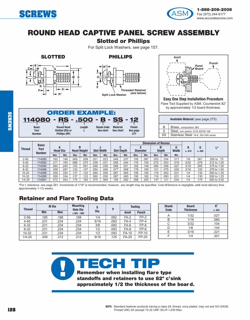
128
1-888-208-2008Fax (973) 244-9177www.accuratescrew.comSCREWS
SC
RE
WS
2-56 114080 .162 .146 .069 .059 .031 .023 .048 .037 .100 .087 .053 .034 .017 1/8 .061 .250 to .754-40 114082 .211 .193 .086 .075 .039 .031 .058 .044 .118 .105 .072 .053 .019 5/32 .078 .312 to 1.006-32 114084 .260 .240 .103 .091 .048 .039 .068 .051 .162 .149 .084 .056 .027 3/16 .095 .375 to 1.008-32 114086 .309 .287 .120 .107 .054 .045 .077 .058 .178 .165 .101 .075 .030 3/16 .120 .375 to 1.0010-24 114089 .359 .334 .137 .123 .060 .050 .087 .065 .195 .182 .119 .093 .031 1/4 .130 .500 to 1.2510-32 114088 .359 .334 .137 .123 .060 .050 .087 .065 .195 .182 .119 .093 .031 1/4 .130 .500 to 1.251/4-20 114081 .472 .443 .175 .160 .075 .064 .109 .082 .268 .255 .147 .121 .034 1/4 .175 .500 to 3.00
ROUND HEAD CAPTIVE PANEL SCREW ASSEMBLYSlotted or Phillips
For Split Lock Washers, see page 157.
2-56 .185 .188 .188 1/4 .062 FA-2 FP-24-40 .231 .234 .234 5/16 .093 FA-4 FP-46-32 .231 .234 .234 3/8 .093 FA-6 FP-68-32 .231 .234 .234 1/2 .093 FA-8 FP-810-32 .231 .234 .234 1/2 .093 FA-10 FP-101/4-20 .309 .312 .312 9/16 .125 FA-25 FP-25
Shank Board R1
Code Thickness ± .003
A 1/32 .027B 1/16 .060C 3/32 .104D 1/8 .144E 3/16 .221F 1/4 .301
Thread M Dia
Min Max
MountingHole Dia+.003 -.000
SDia
PTooling
Anvil Punch
Easy One Step Installation ProcedureFlare Tool Supplied by ASM. Countersink 82°
by approximately 1/2 board thickness.
ThreadBasicPart
Number
Dimension of RecessL*
B Brass, composition 360S Steel, low carbon 1018 ASTM 108
SS Stainless Steel 18-8, 302-304 series
Available Material (see page 275)
Retainer and Flare Tooling Data
*For L tolerance, see page 281. Increments of 1/16" is recommended, however , any length may be specified. Cost dif ference is negligible, addi ional delivery timeapproximately 1-1/2 weeks.
NOTE: Standard fastener products having a class 2A thread, once plated, may not exit GO GAGE.Thread UNC-3A (except 10-32 UNF-3A) R =.030 Max.
ORDER EXAMPLE:114080
BasicPart
Number
RSRound Head
Slotted (RS) orPhillips (RP)
.500Length:
L
SSMaterial:See chart
--- 12Finish:
See page277
-BShank Code:
See chart
-
Max Min Max Min Max Min Max Min Max Min Max Min
AHead Dia
BHead Height
JSlot Width
CSlot Depth
EDiameter
B1
DepthD
WidthMin
K± .010
G± .005
SLOTTED PHILLIPS
! TECH TIPRemember when installing flare typestandoffs and retainers to use 82º c’sinkapproximately 1/2 the thickness of the boar d.

129
1-888-208-2008Fax (973) 244-9177
www.accuratescrew.com SCREWS
SC
RE
WS
CAPTIVE SOCKET HEAD CAP SCREWS1960 Series
For Captive Socket Head Cap Screw assembly, see page 130-131.
S Steel, ASTM-A-108-93 (12L14) QQ-S-637SS Stainless Steel, 18-8, 302-304 series
Available Material (see page 275)
Lead Point Option
*For L tolerance, see page 281. Increments of 1/16" is recommended, however , any length may be specified. Cost dif ference is negligible, addi ional delivery timeapproximately 1-1/2 weeks.
NOTE: Standard fastener products having a class 2A thread, once plated, may not exit GO GAGE.Thread UNC-3A (except 10-32 UNF-3A) R =.030 Max.
See page 283 for Hex size.
ORDER EXAMPLE:- - -114112
BasicPart
Number
.500Length:
L
SSMaterial:See chart
12Finish:
See page 277
To add the Lead Point option, prefix P to part number.EXAMPLE: P114112-.500-SS-12To order Slotted Hex Head, add SDS to part number . EXAMPLE: 114112-.500-SS-SDS-12
BasicPart
NumberThread
Max Min Max Min
L* K± .010
B± .005
PKRef.Only
D H
114112 2-56 .140 .134 .086 .083 .250 - 1.00 1/8 .061 .17114114 4-40 .183 .176 .112 .108 .250 - 1.00 5/32 .078 .22114116 6-32 .226 .218 .138 .134 .375 - 1.25 3/16 .095 .26114118 8-32 .270 .262 .164 .159 .375 - 1.25 3/16 .120 .28114127 10-24 .312 .303 .190 .185 .500 - 1.50 1/4 .130 .36114120 10-32 .312 .303 .190 .185 .500 - 1.50 1/4 .130 .36114121 1/4-20 .375 .365 .250 .244 .500 - 3.00 1/4 .175 .39114111 1/4-28 .375 .365 .250 .244 .375 - 3.00 1/4 .175 .39114113 5/16-18 .469 .457 .312 .306 .500 - 3.50 3/8 .230 .55114115 3/8-16 .562 .550 .375 .368 .500 - 5.00 3/8 .280 .59114117 7/16-14 .656 .642 .438 .430 .750 - 4.00 3/8 .344 .62114119 1/2-13 .750 .735 .500 .492 .750 - 8.00 3/8 .400 .66
ALSO AVAILABLE AS ANFMR2002 ASSEMBLY
(see pages 110-112for more information)
Order Example:114112-.500-U-SS-12
Split Lock Washer (GF)See page 157 for details.
External Tooth Lock Washer (JF)See page 157 for details.
Internal Tooth Lock Washer (HF)See page 157 for details.
* Fully threaded up to the flatwasher.
** Maximum length 1.50 inches.
SOCKET HEAD CAP SCREW ASSEMBLY - FULL THREAD
ORDER EXAMPLE:GFAssembly
w/Split (GF),Internal (HF) or
External (JF)
114112Part
Number:See page 129
SSMaterial:See page
129
- - 12Finish:
See page277
-.500Length:
L
-
! TECH TIPAll socket cap screws are class 3Athreads unless other specified.

130
1-888-208-2008Fax (973) 244-9177www.accuratescrew.comSCREWS
SC
RE
WS
CAPTIVE SOCKET HEAD CAP SCREW ASSEMBLY
External Tooth Lock Washer (J)See page 157 for details.
Split Lock Washer (G)See page 157 for details.
Internal Tooth Lock Washer (H)See page 157 for details.
Split Lock Washer (GF)See page 157 for details.
External Tooth Lock Washer (JF)See page 157 for details.
Internal Tooth Lock Washer (HF)See page 157 for details.
NOTE: Standard fastener products having a class 2A thread, once plated, may not exit GO GAGE.Thread UNC-3A (except 10-32 UNF-3A) R =.030 Max.
Screw Outside Dia T* ± .005Size ± .010 Thickness
2 .187 .0204 .255 .0306 .312 .0308 .312 .03010 .375 .0301/4 .500 .045**5/16 .625 .085
Captive Washer Specifications
Belleville Washer see page 116.
See page 129 for screw dimensions.
* Fully threaded up to the flatwasher.
** Maximum length 1.50 inches.
SOCKET HEAD CAP SCREW ASSEMBLY - FULL THREAD
ORDER EXAMPLE:G
Assemblyw/Split (G)L’Washer & Flat Washer
114112Part
Number:See page 129
SSMaterial:See page
129
- - 12Finish:
See page277
-.500Length:
L
-
ORDER EXAMPLE:J
Assemblyw/External (J)
L’Washer & Flat Washer
114112Part
Number:See page 129
SSMaterial:See page
129
- - 12Finish:
See page277
-.500Length:
L
-
ORDER EXAMPLE:H
Assemblyw/Internal (H)
L’Washer & Flat Washer
114112Part
Number:See page 129
SSMaterial:See page
129
- - 12Finish:
See page277
-.500Length:
L
-
ORDER EXAMPLE:GFAssembly
w/Split (GF),Internal (HF) or
External (JF)
114112Part
Number:See page 129
SSMaterial:See page
129
- - 12Finish:
See page277
-.500Length:
L
-

131
1-888-208-2008Fax (973) 244-9177
www.accuratescrew.com SCREWS
SC
RE
WS
SOCKET HEAD CAP SCREWCAPTIVE PANEL SCREW ASSEMBLY
See page 157 for Split Lock Washer.
2-56 .185 .188 .188 1/4 .062 FA-2 FP-24-40 .231 .234 .234 5/16 .093 FA-4 FP-46-32 .231 .234 .234 3/8 .093 FA-6S FP-6S8-32 .231 .234 .234 1/2 .093 FA-8S FP-8S10-32 .231 .234 .234 1/2 .093 FA-10S FP-10S1/4-20 .309 .312 .312 9/16 .125 FA-25S FP-25S
Shank Board R1
Code Thickness ± .003
A 1/32 .027B 1/16 .060C 3/32 .104D 1/8 .144E 3/16 .221F 1/4 .301
Thread M Dia
Min Max
MountingHole Dia+.003 -.000
SDia
P Tooling
Anvil Punch
Easy One Step Installation ProcedureFlare Tool supplied by ASM.
Countersink 82° by approximately1/2 board thickness.
S Steel, ASTM-A-108-93 (12L14) QQ-S-637
SS Stainless Steel, 18-8, 302-304 series
Available Material (see page 275)
Retainer and Flare Tooling Data
(see below)
*For L tolerance, see page 281. Increments of 1/16" is recommended, however , any length may be specified. Cost dif ference is negligible, addi ional delivery timeapproximately 1-1/2 weeks.
BasicPart
NumberThread
Max Min Max Min
L* K± .010
B± .005
D H
114112 2-56 .140 .134 .086 .083 .250-0.625 1/8 .061114114 4-40 .183 .176 .112 .108 .250-0.625 5/32 .078114116 6-32 .226 .218 .138 .134 .375-1.25 3/16 .095114118 8-32 .270 .262 .164 .159 .375-1.25 3/16 .120114127 10-24 .312 .303 .190 .185 .500-1.50 1/4 .130114120 10-32 .312 .303 .190 .185 .500-1.50 1/4 .130114121 1/4-20 .375 .365 .250 .244 .500-3.00 1/4 .175114111 1/4-28 .375 .365 .250 .244 .375-3.00 1/4 .175114113 5/16-18 .469 .457 .312 .306 .500-3.50 3/8 .230114115 3/8-16 .562 .550 .375 .368 .500-5.00 3/8 .280114117 7/16-14 .656 .642 .438 .430 .750- 4.00 3/8 .344114119 1/2-13 .750 .735 .500 .492 .750-8.00 3/8 .400
ORDER EXAMPLE:SSMaterial:See chart
114112BasicPart
Number
BShank Code:
See chart
- - 12Finish:
See page277
-.500Length:
L
-
NOTE: Standard fastener products having a class 2A thread, once plated, may not exit GO GAGE.Thread UNC-3A (except 10-32 UNF-3A) R =.030 Max.

132
1-888-208-2008Fax (973) 244-9177www.accuratescrew.comSCREWS
SC
RE
WS
HEX HEAD CAPTIVE MACHINE SCREWFor Hex Captive Machine Screw assembly, see pages 133-134. For Retainer Washers, see page 147.
S Steel, low carbon 1018 ASTM 108
SS Stainless Steel, 18-8, 302-304 series
Available Material (see page 275)
Lead Point Option
*For L tolerance, see page 281. Increments of 1/16" is recommended, however , any length may be specified. Cost dif ference is negligible, addi ional delivery timeapproximately 1-1/2 weeks.
NOTE: Standard fastener products having a class 2A thread, once plated, may not exit GO GAGE.Thread UNC-3A (except 10-32 UNF-3A) R =.030 Max.
ORDER EXAMPLE:- - -114102
BasicPart
Number
.500Length:
See chartor fill in length
SSMaterial:See chart
12Finish:
See page 277
BasicPart
NumberThread
Max Min Max Min
L* C
Min
K± .010
B± .005
PKRef.Only
D H
114102 2-56 .125 .120 .050 .040 .250-.625 .134 1/8 .061 .17114104 4-40 .188 .181 .060 .049 .250-.625 .202 5/32 .078 .22114106 6-32 .250 .244 .093 .080 .375-1.25 .272 3/16 .095 .26114108 8-32 .250 .244 .110 .096 .500-1.25 .272 3/16 .120 .28114107 10-24 .312 .305 .120 .105 .500-1.25 .340 1/4 .130 .36114110 10-32 .312 .305 .120 .105 .500-1.25 .340 1/4 .130 .36114109 1/4-20 .438 .428 .163 .150 .625-1.25 .488 1/4 .175 .39114103 5/16-18 .500 .489 .211 .195 .625-1.25 .557 1/4 .230 .43114105 3/8-16 .562 .551 .243 .226 .625-1.50 .628 3/8 .280 .59
To add the Lead Point, add heprefix P to part number.EXAMPLE: P114104-.500-SS-12
To order SLOTTED Hex Head, addSDS to part number.EXAMPLE: 114104-.500-SS-SDS-12
Lead Point Option Slotted Hex Head
ALSO AVAILABLE AS ANFMR2002 ASSEMBLY
(see pages 110-112for more information)
Order Example:114102-.500-U-SS-12
! TECH TIPDownloadable 3D CAD models available in thefollowing formats: DXF, Pro/E, IGES and STEPat www.accuratescrew.com.

133
1-888-208-2008Fax (973) 244-9177
www.accuratescrew.com SCREWS
SC
RE
WS
Split Lock Washer (G)See page 157 for details.
Internal Tooth Lock Washer (H)See page 157 for details.
HEX HEAD MACHINE SCREW ASSEMBLY - FULL THREAD
HEX HEAD CAPTIVE MACHINE SCREW ASSEMBLY
External Tooth Lock Washer (J)See page 157 for details.
Split Lock Washer (GF)See page 157 for details.
External Tooth Lock Washer (JF)See page 157 for details.
Internal Tooth Lock Washer (HF)See page 157 for details.
Belleville Washer see page 116.
Screw Outside Dia T ± .005Size ± .010 Thickness
2 .187 .0204 .255 .0306 .312 .0308 .312 .03010 .375 .0301/4 .500 .045**5/16 .625 .085
Captive Washer Specifications
See page 132 for screw dimensions.
* Fully threaded up to theflat washer.
** Maximum length 1.50inches.
NOTE: Standard fastener products having a class 2A thread, once plated, may not exit GO GAGE.Thread UNC-3A (except 10-32 UNF-3A) R =.030 Max.
ORDER EXAMPLE:G
Assemblyw/Split (G)L’Washer & Flat Washer
114102Part
Number:See page 132
SSMaterial:See page
132
- - 12Finish:
See page277
-.500Length:
L
-
ORDER EXAMPLE:J
Assemblyw/External (J)
L’Washer & Flat Washer
114102Part
Number:See page 132
SSMaterial:See page
132
- - 12Finish:
See page277
-.500Length:
L
-
ORDER EXAMPLE:H
Assemblyw/Internal (H)
L’Washer & Flat Washer
114102Part
Number:See page 132
SSMaterial:See page
132
- - 12Finish:
See page277
-.500Length:
L
-
ORDER EXAMPLE:GFAssembly
w/Split (GF),Internal (HF) or
External (JF)
114102Part
Number:See page 132
SSMaterial:See page
132
- - 12Finish:
See page277
-.500Length:
L
-

134
1-888-208-2008Fax (973) 244-9177www.accuratescrew.comSCREWS
SC
RE
WS
NOTE: Standard fastener products having a class 2A thread, once plated, may not exit GO GAGE.Thread UNC-3A (except 10-32 UNF-3A) R =.030 Max.
Retainer and Flare Tooling Data
HEX HEAD MACHINE SCREWCAPTIVE PANEL SCREW ASSEMBLY
See page 157 for Split Lock Washer.
Easy One Step Installation ProcedureFlare Tool Supplied by ASM.
Countersink 82° by approximately1/2 board thickness.
S Steel, low carbon 1018 ASTM 108
SS Stainless Steel, 18-8, 302-304 series
Available Material (see page 275)
2-56 .185 .188 .188 1/4 .062 FA-2 FP-24-40 .231 .234 .234 5/16 .093 FA-4 FP-46-32 .231 .234 .234 3/8 .093 FA-6 FP-68-32 .231 .234 .234 1/2 .093 FA-8 FP-810-32 .231 .234 .234 1/2 .093 FA-10 FP-101/4-20 .309 .312 .312 9/16 .125 FA-25 FP-25
Shank Board R1
Code Thickness ± .003
A 1/32 .027B 1/16 .060C 3/32 .104D 1/8 .144E 3/16 .221F 1/4 .301
Thread M Dia
Min Max
MountingHole Dia+.003 -.000
SDia
P Tooling
Anvil Punch
(see below)
*For L tolerance, see page 281. Increments of 1/16" is recommended, however , any length may be specified. Cost dif ference is negligible, addi ional delivery timeapproximately 1-1/2 weeks.
BasicPart
NumberThread
Max Min Max Min
L* C
Min
TL± .010
B± .005
D H
114102 2-56 .125 .120 .050 .040 .375-.750 .134 1/8 .061114104 4-40 .188 .181 .060 .049 .375-1.00 .202 5/32 .078114106 6-32 .250 .244 .093 .080 .500-1.00 .272 3/16 .095114108 8-32 .250 .244 .110 .096 .500-1.00 .272 3/16 .120114107 10-24 .312 .305 .120 .105 .750-1.25 .340 1/4 .130114110 10-32 .312 .305 .120 .105 .750-1.25 .340 1/4 .130114109 1/4-20 .438 .428 .163 .150 .750-3.00 .488 1/4 .175114105 3/8-16 .562 .551 .243 .226 .625-1.50 .628 3/8 .280
ORDER EXAMPLE:SSMaterial:See chart
114102BasicPart
Number
BShank Code:
See chart
- - 12Finish:
See page277
-.500Length:
L
-

135
1-888-208-2008Fax (973) 244-9177
www.accuratescrew.com SCREWS
SC
RE
WS
B Brass, Composition 360S Steel, low carbon 1018 ATSM 108
SS Stainless Steel,18-8, 302-304 series
Available Material (see page 275)
FLAT HEAD CAPTIVE MACHINE SCREWSPhillips
For Retainer Washers, see page 147.
FLAT HEAD CAPTIVE MACHINE SCREWSSlotted
For Metric style see page 156.
114122 2-56 .172 .147 .051 .102 .089 .063 .047 1/8 .061 .43-.625 .17114124 4-40 .225 .195 .067 .128 .115 .089 .073 5/32 .078 .43-.625 .22114126 6-32 .279 .244 .083 .174 .161 .106 .083 3/16 .095 .43-2.00 .26114128 8-32 .332 .292 .100 .189 .176 .121 .098 3/16 .120 .43-2.00 .28114130 10-32 .385 .340 .116 .204 .191 .136 .113 1/4 .130 .43-2.00 .36114123 1/4-20 .507 .452 .153 .283 .270 .171 .148 .1/4 .175 .43-3.00 .39114125 5/16-18 .635 .568 .191 .365 .352 .216 .194 1/4 .230 .50-3.50 .43
BasicPart
NumberThread
Max Min
DHead Dia
Max Min
WDiameter
HRef
Max Min
YDepth K
± .010B
± .005L*
PKRefOnly
B Brass, Composition 360S Steel, low carbon 1018 ATSM 108
SS Stainless Steel, 18-8,302-304 series, ASTMA580/A580M-98
Available Material (see page 275)
Self-Locking Device available, see page 109.
*For L tolerance, see page 281.Increments of 1/16" is recommended,however, any length may be specified.Cost difference is negligible, additionaldelivery time approximately 1-1/2 weeks.
NOTE: Standard fastener products having a class 2A thread, once plated, may not exit GO GAGE.Thread UNC-3A (except 10-32 UNF-3A) R =.030 Max.
ORDER EXAMPLE:- - -114122
BasicPart
Number
.430Length
SSMaterial:See chart
12Finish:
See page277
To add the Lead Point, add the prefix P to part number. EXAMPLE: P114122-.430-SS-12Any one dimension change add to part number:EXAMPLE: 114122-.500-SS-12 (K=3/16)
ORDER EXAMPLE:- - -904960
BasicPart
Number
.430Length
SSMaterial:See chart
12Finish:
See page277
To add the Lead Point, add the prefix P to part number. EXAMPLE: P904960-.430-SS-12Any one dimension change add to part number:EXAMPLE: 904960-.500-SS-12 (K=3/16)
904960 2-56 .172 .147 .051 .031 .023 .023 .015 1/8 .061 .430-1.00 .17904962 4-40 .225 .195 .067 .039 .031 .030 .020 5/32 .078 .430-1.50 .22904964 6-32 .279 .244 .083 .048 .039 .038 .024 3/16 .095 .430-3.00 .26904966 8-32 .332 .292 .100 .054 .045 .045 .029 3/16 .120 .430-3.00 .28904968 10-32 .385 .340 .116 .060 .050 .053 .034 1/4 .130 .430-3.00 .36904970 1/4-20 .507 .452 .153 .075 .064 .070 .046 1/4 .175 .430-4.00 .39904972 5/16-18 .635 .568 .191 .084 .072 .088 .058 1/4 .230 .500-3.50 .43
BasicPart
NumberThread
Max Min
AHead Dia
Max Min
JSlot Width
HRef
Max Min
TSlot Depth K
± .010B
± .005L*
PKRefOnly

136
1-888-208-2008Fax (973) 244-9177www.accuratescrew.comSCREWS
SC
RE
WS
FLAT HEAD CAPTIVE MACHINE SCREWS Phillips
For Retainer Washers, see page 147.
Self-Locking Device available, see page 109.
FLAT HEAD CAPTIVE MACHINE SCREWS Slotted
S Steel, low carbon 1018 ATSM 108SS Stainless Steel,
18-8, 302-304 series
Available Material(see page 275)
S Steel, low carbon 1018 ATSM 108SS Stainless Steel, 18-8, 302-304
series, ASTMA580/A580M-98
Available Material(see page 275)
*L +.000-.031 recommended incrementsof 1/16, however, any length may bespecified. Cost difference is negligible,additional delivery time approximately 1-1/2 weeks.
NOTE: Standard fastener products having a class 2A thread, once plated, may not exit GO GAGE.Thread UNC-3A (except 10-32 UNF-3A) R =.030 Max.
*L +.000-.031 recommended incrementsof 1/16, however, any length may bespecified. Cost difference is negligible,additional delivery time approximately1-1/2 weeks.
ORDER EXAMPLE:- - -114215
BasicPart
Number
.500Length
SSMaterial:See chart
12Finish:
See page277
To add the Lead Point, add the prefix P to part number. EXAMPLE: P114215-.500-SS-12Any one dimension change add to part number:EXAMPLE: 114215-.500-SS-12 (K=3/16)
ORDER EXAMPLE:- - -904961
BasicPart
Number
.500Length
SSMaterial:See chart
12Finish:
See page277
To add the Lead Point, add the prefix P to part number. EXAMPLE: P904961-.430-SS-12Any one dimension change add to part number:EXAMPLE: 904961-.500-SS-12 (K=3/16)
114215 2-56 .172 .143 .037 .097 .087 .063 .033 1/8 .061 .430-.625 .17114217 4-40 .225 .191 .049 .136 .126 .089 .050 5/32 .078 .430-.625 .22114219 6-32 .279 .238 .060 .162 .152 .106 .065 3/16 .095 .430-2.00 .26114221 8-32 .332 .285 .072 .191 .179 .124 .081 3/16 .120 .430-2.00 .28114223 10-32 .385 .333 .083 .225 .213 .147 .097 1/4 .130 .430-2.00 .36114225 1/4-20 .507 .442 .110 .294 .282 .192 .136 1/4 .175 .500-3.00 .39
BasicPart
NumberThread
Max Min
DHead Dia
Max Min
WDiameter
HRef
Max Min
YDepth K
± .010B
± .005L*
PKRefOnly
904961 2-56 .172 .143 .037 .031 .023 .019 .012 1/8 .061 .430-1.00 .17904963 4-40 .225 .191 .049 .039 .031 .024 .017 5/32 .078 .430-1.50 .22904965 6-32 .279 .238 .060 .048 .039 .030 .022 3/16 .095 .430-3.00 .26904967 8-32 .332 .285 .072 .054 .045 .036 .027 3/16 .120 .430-3.00 .28904969 10-32 .385 .333 .083 .060 .050 .042 .031 1/4 .130 .430-3.00 .36904971 1/4-20 .507 .442 .110 .075 .064 .055 .042 1/4 .175 .500-4.00 .39904973 5/16-18 .635 .556 .138 .084 .072 .069 .053 1/4 .230 .500-3.50 .43
BasicPart
NumberThread
Max Min
AHead Dia
Max Min
JSlot Width
HRef
Max Min
TSlot Depth K
± .010B
± .005L*
PKRefOnly
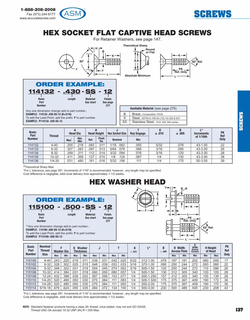
137
1-888-208-2008Fax (973) 244-9177
www.accuratescrew.com SCREWS
SC
RE
WSB Brass, Composition 70/30
S Steel, ASTM-A-108-93 (12L14) QQ-S-637SS Stainless Steel, 18-8, 302-304 series
Available Material (see page 275)
HEX SOCKET FLAT CAPTIVE HEAD SCREWSFor Retainer Washers, see page 147.
114132 4-40 .255 .218 .083 .011 1/16 .062 .055 5/32 .078 .43-1.50 .22114133 6-32 .307 .263 .097 .013 5/64 .078 .066 3/16 .095 .43-3.00 .26114134 8-32 .359 .311 .112 .014 3/32 .094 .076 3/16 .120 .43-3.00 .28114135 10-32 .411 .359 .127 .015 1/8 .125 .087 1/4 .130 .43-3.00 .36114136 1/4-20 .531 .480 .161 .016 5/32 .156 .111 1/4 .175 .50-3.50 .39
115100 4-40 .243 .225 .019 .011 .039 .031 .042 .025 5/32 .312-1.00 .078 .187 .181 .202 .060 .049 .17115102 6-32 .328 .302 .025 .015 .048 .039 .053 .033 3/16 .375-1.00 .095 .250 .244 .272 .093 .080 .22115104 8-32 .348 .322 .031 .019 .054 .045 .074 .052 3/16 .500-1.50 .120 .250 .244 .272 .110 .096 .26115106 10-32 .414 .384 .031 .019 .060 .050 .080 .057 1/4 .500-1.50 .130 .312 .305 .340 .120 .105 .28115108 12-24 .432 .398 .039 .022 .067 .056 .103 .077 1/4 .500-1.250 .157 .312 .305 .340 .155 .139 .28115110 1/4-20 .520 .480 .050 .030 .075 .064 .111 .083 1/4 .500-1.500 .175 .375 .367 .409 .190 .172 .36115112 1/4-28 .520 .480 .050 .030 .075 .064 .111 .083 1/4 .500-2.00 .175 .375 .367 .409 .190 .172 .36115114 5/16-18 .676 .624 .055 .035 .084 .072 .134 .100 1/4 .500-3.00 .230 .500 .489 .545 .230 .208 .43
BasicPart
Number
NominalThread
Size
K± .010
B± .005
L* PKRefOnly
D WidthAcross Flats
H Heightof Head
CWidthAcrossCorners
HEX WASHER HEAD
NOTE: Standard fastener products having a class 2A thread, once plated, may not exit GO GAGE.Thread UNC-3A (except 10-32 UNF-3A) R =.030 Max.
†Theoretical Sharp Max.*For L tolerance, see page 281. Increments of 1/16" is recommended, however , any length may be specified.Cost difference is negligible, addi ional delivery time approximately 1-1/2 weeks.
*For L tolerance, see page 281. Increments of 1/16" is recommended, however , any length may be specified.Cost difference is negligible, addi ional delivery time approximately 1-1/2 weeks.
ORDER EXAMPLE:- - -114132
BasicPart
Number
.430Length
SSMaterial:See chart
12Finish:
See page277
Any one dimension change add to part number .EXAMPLE: 114132-.430-SS-12 (K=3/16)To add the Lead Point, add the prefix P to part number. EXAMPLE: P114132-.430-SS-12
ORDER EXAMPLE:- - -115100
BasicPart
Number
.500Length
SSMaterial:See chart
12Finish:
See page277
**Any one dimension change add to part number .EXAMPLE: 115100-.500-SS-12 (K=3/16)To add the Lead Point, add the prefix P to part number. EXAMPLE: P115100-.500-SS-12
BasicPart
NumberThread
AHead Dia
HHead Height
JHex Socket Size
Nominal
TKey Engage.
Min
K± .010
B± .005
L*Increments of 1/16th
PKRefOnlyMax
† Abs.Min Ref. Flush
Tol.
Max Min Max Min Max Min Max Min
FWasher Dia
U WasherThickness
J T
Max Min Min Min Max

138
1-888-208-2008Fax (973) 244-9177www.accuratescrew.comSCREWS
SC
RE
WS
NOTE: Standard fastener products having a class 2A thread, once plated, may not exit GO GAGE.Thread UNC-3A (except 10-32 UNF-3A) R =.030 Max.
CAPTIVE PANEL SCREW ASSEMBLY LOW PROFILE100° Flat Head - Slotted or Phillips
CAPTIVE PANEL SCREW ASSEMBLY LOW PROFILE82° Flat Head - Slotted or Phillips
904960 2-56904962 4-40904964 6-32904966 8-32904968 10-32904970 1/4-20
Part Number Thread
904961 2-56904963 4-40904965 6-32904967 8-32904969 10-32904971 1/4-20
Part Number Thread
114122 2-56114124 4-40114126 6-32114128 8-32114130 10-32114123 1/4-20
Part Number Thread
For screwdimensionssee page 136.
S Steel Alloy, low carbon 1018 ASTM 108SS Stainless Steel, 18-8, 302-304 Series
ASTMA580/A580M-98
Available Material (see page 275)
Easy One StepInstallation ProcedureFlare Tool supplied by ASM.
Countersink 82° by approximately1/2 board thickness.
Slotted
Slotted
S Steel Alloy, low carbon 1018 ASTM 108SS Stainless Steel, 18-8, 302-304 series
Available Material (see page 275)
Part Number Thread
114215 2-56114217 4-40114219 6-32114221 8-32114223 10-32114225 1/4-20
Retainer and Flare Tooling Data
2-56 .185 .188 .188 1/4 .122 AFH-2 FP-24-40 .231 .234 .234 5/16 .154 AFH-4 FP-46-32 .231 .234 .234 3/8 .185 AFH-6 FP-68-32 .231 .234 .234 1/2 .220 AFH-8 FP-810-32 .231 .234 .234 1/2 .252 AFH-10 FP-101/4-20 .309 .312 .312 5/8 .326 AFH-25 FP-25
Shank Board R1
Code Thickness ± .003
A 1/32 .027B 1/16 .060C 3/32 .104D 1/8 .144E 3/16 .221F 1/4 .301
Thread M Dia
Min Max
MountingHole Dia+.003 -.000
SDia
P Tooling
Anvil Punch
Retainer and Flare Tooling Data
2-56 .185 .188 .188 1/4 .108 AFH-2 FP-24-40 .231 .234 .234 5/16 .144 AFH-4 FP-46-32 .231 .234 .234 3/8 .173 AFH-6 FP-68-32 .231 .234 .234 1/2 .185 AFH-8 FP-810-32 .231 .234 .234 1/2 .196 AFH-10 FP-101/4-20 .309 .312 .312 5/8 .280 AFH-25 FP-25
Shank Board R1
Code Thickness ± .003
A 1/32 .027B 1/16 .060C 3/32 .104D 1/8 .144E 3/16 .221F 1/4 .301
Thread M Dia
Min Max
MountingHole Dia+.003 -.000
SDia
P Tooling
Anvil Punch
For screwdimensions,see page 135.
Phillips
Easy One StepInstallation ProcedureFlare Tool supplied by ASM.
Countersink 82° by approximately1/2 board thickness.
ORDER EXAMPLE:- - -904961
BasicPart
Number
.500Length
SSMaterial:See chart
12Finish:
See page277
BShank Code:
See chart
-
ORDER EXAMPLE:- - -904960
BasicPart
Number
.500Length
SSMaterial:See chart
12Finish:
See page277
BShank Code:
See chart
-
Phillips

139
1-888-208-2008Fax (973) 244-9177
www.accuratescrew.com SCREWS
SC
RE
WS
HEX SOCKET LOW HEAD CAP SCREW CAPTIVEFor Hex Socket Low Head Cap Scr ew Assembly
For Retainer Washers, see page 147.
**B Brass, Composition 360S Steel, ASTM-A-108-93 (12L14) QQ-S-637
SS Stainless Steel, 18-8, 302-304 series
Available Material (see page 275)
116050 4-40 .112 .183 .178 .056 .053 .050 .038 .078 5/32 .375-1.25 .22116052 6-32 .138 .226 .221 .069 .066 .062 .050 .095 3/16 .375-1.25 .26116054 8-32 .164 .270 .265 .082 .079 .078 .060 .120 3/16 .375-1.25 .28116056 10-32 .190 .312 .307 .095 .092 .093 .072 .130 1/4 .375-1.50 .36116058 1/4-20 .250 .375 .369 .125 .121 .125 .094 .175 1/4 .375-3.00 .39116060 5/16-18 .312 .437 .431 .156 .152 .156 .120 .230 1/4 .500-3.00 .43
L tolerance-1" under +0-1/32above +0-1/16 recommendedincrements of 1/16 howeverany length may be specified.Cost difference is negligible,additional delivery timeapproximately 1-1/2 weeks.
NOTE: Standard fastener products having a class 2A thread, once plated, may not exit GO GAGE.Thread UNC-3A (except 10-32 UNF-3A) R =.030 Max.
ORDER EXAMPLE:- - -116054
BasicPart
Number
.500Length
SSMaterial:See chart
12Finish:
See page277
To add the Lead Point, add the prefix P to part number.EXAMPLE: P116050-.500-SS-12
Any one dimension change add to part number:EXAMPLE: 116054-.500-SS-12 (K=3/16)
BasicPart
NumberThread
BasicScrewDia
D H
Max Min Max Min
WSocket
Size
TEngage.
Min
G± .005
K± .010
PKRefOnly
L*
HEX SOCKET LOW HEAD CAP SCREW ASSEMBLYSplit Lock Washer (G)
See page 157 for details.External Tooth Lock Washer (J)
See page 157 for details.Internal Tooth Lock Washer (H)
See page 157 for details.
ORDER EXAMPLE:116054 - 500 - SS - G - 12
BasicPart
Number
Length Material:See chart
Assy withSplit (G)L’Washerand FlatWasher
Finish:See page
277
ORDER EXAMPLE:116054 - 500 - SS - H - 12
BasicPart
Number
Length Material:See chart
Assy withInternal (H)L’Washerand FlatWasher
Finish:See page
277
ORDER EXAMPLE:116054 - 500 - SS - J - 12
BasicPart
Number
Length Material:See chart
Assy withExternal (J)
L’Washerand FlatWasher
Finish:See page
277
ALSO AVAILABLE AS ANFMR2002 ASSEMBLY
(see pages 110-112for more information)
Order Example:116050-.500-U-SS-12
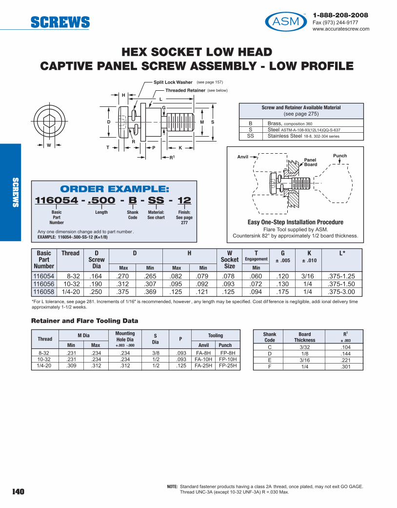
140
1-888-208-2008Fax (973) 244-9177www.accuratescrew.comSCREWS
SC
RE
WS
116054 8-32 .164 .270 .265 .082 .079 .078 .060 .120 3/16 .375-1.25116056 10-32 .190 .312 .307 .095 .092 .093 .072 .130 1/4 .375-1.50116058 1/4-20 .250 .375 .369 .125 .121 .125 .094 .175 1/4 .375-3.00
L*
HEX SOCKET LOW HEADCAPTIVE PANEL SCREW ASSEMBLY - LOW PROFILE
B Brass, composition 360S Steel ASTM-A-108-93(12L14)QQ-S-637
SS Stainless Steel 18-8, 302-304 series
Screw and Retainer Available Material(see page 275)
Easy One-Step Installation ProcedureFlare Tool supplied by ASM.
Countersink 82° by approximately 1/2 board thickness.
8-32 .231 .234 .234 3/8 .093 FA-8H FP-8H10-32 .231 .234 .234 1/2 .093 FA-10H FP-10H1/4-20 .309 .312 .312 1/2 .125 FA-25H FP-25H
Shank Board R1
Code Thickness ± .003
C 3/32 .104D 1/8 .144E 3/16 .221F 1/4 .301
Thread M Dia
Min Max
MountingHole Dia+.003 -.000
SDia
PTooling
Anvil Punch
Retainer and Flare Tooling Data
(see page 157)
(see below)
*For L tolerance, see page 281. Increments of 1/16" is recommended, however , any length may be specified. Cost dif ference is negligible, addi ional delivery timeapproximately 1-1/2 weeks.
NOTE: Standard fastener products having a class 2A thread, once plated, may not exit GO GAGE.Thread UNC-3A (except 10-32 UNF-3A) R =.030 Max.
ORDER EXAMPLE:-116054
BasicPart
Number
.500Length
SSMaterial:See chart
12Finish:
See page277
BShankCode
- - -
Any one dimension change add to part number . EXAMPLE: 116054-.500-SS-12 (K=1/8)
Basic Part
Number
Thread DScrew
Dia Max Min Max Min
WSocket
Size
TEngagement
Min
G± .005
K± .010
D H

141
1-888-208-2008Fax (973) 244-9177
www.accuratescrew.com SCREWS
SC
RE
WS
HEX SOCKET BUTTON HEAD SCREWS CAPTIVEFor Hex Socket Button Head Screw Assembly
For Retainer Washers, see page147.
116064 4-40 .213 .201 .059 .051 .015 .1/16 .062 .035 .078 5/32 .250-.500 .22116066 6-32 .262 .250 .073 .063 .015 5/64 .078 .044 .095 3/16 .250-.625 .26116068 8-32 .312 .298 .087 .077 .015 3/32 .094 .052 .120 3/16 .250-.750 .28116070 10-32 .361 .347 .101 .091 .020 1/8 .125 .070 .130 1/4 .250-1.00 .36116078 1/4-20 .437 .419 .132 .122 .031 5/32 .156 .087 .175 1/4 .375-1.00 .39116080 5/16-18 .547 .527 .166 .152 .031 3/16 .188 .105 .230 1/4 .375-1.00 .43
BasicPart
NumberThread
Max Max Min
HDW
Nom.T
MinG
± .005K
± .010
PKRefOnlyMin
SHeadSide
HeightRef.
L*
B Brass, Composition 70/30S Steel, ASTM-A-108-93 (12L14) QQ-S-637
SS Stainless Steel, 18-8, 302-304 series
Available Material (see page 275)
NOTE: Standard fastener products having a class 2A thread, once plated, may not exit GO GAGE.Thread UNC-3A (except 10-32 UNF-3A) R =.030 Max.
*L tolerance-1" under +0-1/32 above +0-1/16recommended increments of1/16 however any lengthmay be specified. Costdifference is negligible,addi ional delivery timeapproximately 1-1/2 weeks.
ORDER EXAMPLE:- - -116064
BasicPart
Number
.500Length
SSMaterial:See chart
12Finish:
See page277
To add the Lead Point, add the prefix P to part number.EXAMPLE: P116064-.500-SS-12Any one dimension change add to part number:EXAMPLE: 116064-.500-SS-12 (K=1/8)
HEX SOCKET BUTTON HEAD CAP SCREW ASSEMBLYSplit Lock Washer (G)
See page 157 for details.External Tooth Lock Washer (J)
See page 157 for details.Internal Tooth Lock Washer (H)
See page 157 for details.
ORDER EXAMPLE:116064 - 500 - SS - G - 12
BasicPart
Number
Length Material:See chart
Assy withSplit (G)L’Washerand FlatWasher
Finish:See page
277
ORDER EXAMPLE:116064 - 500 - SS - H - 12
BasicPart
Number
Length Material:See chart
Assy withInternal (H)L’Washerand FlatWasher
Finish:See page
277
ORDER EXAMPLE:116064 - 500 - SS - J - 12
BasicPart
Number
Length Material:See chart
Assy withExternal (J)
L’Washerand FlatWasher
Finish:See page
277
ALSO AVAILABLE AS ANFMR2002 ASSEMBLY
(see pages 110-112for more information)
Order Example:116064-.500-U-SS-12
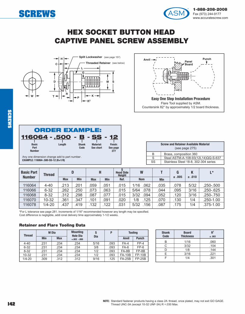
142
1-888-208-2008Fax (973) 244-9177www.accuratescrew.comSCREWS
SC
RE
WS
HEX SOCKET BUTTON HEADCAPTIVE PANEL SCREW ASSEMBLY
116064 4-40 .213 .201 .059 .051 .015 1/16 .062 .035 .078 5/32 .250-.500116066 6-32 .262 .250 .073 .063 .015 5/64 .078 .044 .095 3/16 .250-.625116068 8-32 .312 .298 .087 .077 .015 3/32 .094 .052 .120 3/16 .250-.750116070 10-32 .361 .347 .101 .091 .020 1/8 .125 .070 .130 1/4 .250-1.00116078 1/4-20 .437 .419 .132 .122 .031 5/32 .156 .087 .175 1/4 .375-1.00
Basic PartNumber
ThreadMax Max Min
HD W G± .005
K± .010
L*
Min
T
B Brass, composition 360S Steel ASTM-A-108-93(12L14)QQ-S-637
SS Stainless Steel 18-8, 302-304 series
Screw and Retainer Available Material(see page 275)
Easy One Step Installation ProcedureFlare Tool supplied by ASM.
Countersink 82° by approximately 1/2 board thickness.
Nom Min
*For L tolerance see page 281. Increments of 1/16" recommended however any length may be specified.Cost difference is negligible, addi ional delivery time approximately 1-1/2 weeks.
SHead Side
HeightRef.
4-40 .231 .234 .234 5/16 .093 FA-4 FP-46-32 .231 .234 .234 3/8 .093 FA-6 FP-68-32 .231 .234 .234 1/2 .093 FA-8B FP-8B10-32 .231 .234 .234 1/2 .093 FA-10B FP-10B1/4-20 .309 .312 .312 9/16 .125 FA-25B FP-25B
Thread M Dia
Min Max
MountingHole Dia+.003 -.000
SDia
P Tooling
Anvil Punch
Shank Board R1
Code Thickness ± .003
B 1/16 .060C 3/32 .104D 1/8 .144E 3/16 .221F 1/4 .301
Retainer and Flare Tooling Data
(see page 157)
(see below)
NOTE: Standard fastener products having a class 2A thread, once plated, may not exit GO GAGE.Thread UNC-3A (except 10-32 UNF-3A) R =.030 Max.
ORDER EXAMPLE:-116064
BasicPart
Number
.500Length
SSMaterial:See chart
12Finish:
See page277
BShankCode
- - -
Any one dimension change add to part number . EXAMPLE: 116064-.500-SS-12 (K=1/8)

143
1-888-208-2008Fax (973) 244-9177
www.accuratescrew.com SCREWS
SC
RE
WS
TORX SOCKET BUTTON HEAD CAPTIVE SCREWSFor Torx Socket Button Head Screw Assembly
TORX SOCKET BUTTON HEAD CAPTIVE SCREW ASSEMBLY
TORX HEAD PANEL SCREW ASSEMBLY - FULL THREADCaptive Washers Specifications
4 .255 .0306 .312 .0308 .375 .03010 .375 .0301/4 .375 .045**5/16 .625 .085
*Fully threaded up to the flat washer .**Maximum length 1.50 in.
Split Lock Washer (GF)Also available with
Internal Tooth Lock Washer (HF)and
External Tooth Lock Washer (JF)See page 157 for details.
AS Alloy Steel, Type 4037 ASTM A574-92A-40-45 RC
SS Stainless Steel
Available Material (see page 275)
T116064 4-40 .213 .201 .059 .051 .078 5/32 .250-.500 .22T116066 6-32 .262 .250 .073 .063 .095 3/16 .250-.625 .26T116068 8-32 .312 .298 .087 .077 .120 3/16 .250-.750 .28T116070 10-32 .361 .347 .101 .091 .130 1/4 .250-1.00 .36T116078 1/4-20 .437 .419 .132 .122 .175 1/4 .375-1.00 .39T116080 5/16-18 .547 .527 .166 .152 .230 1/4 .375-1.00 .43
Basic PartNumber
ThreadMax Max Min
HD G± .005
K± .010
L*
Min
PKRefOnly
Split Lock Washer (G)See page 157 for details.
External Tooth Lock Washer (J)See page 157 for details.
Internal Tooth Lock Washer (H)See page 157 for details.
BELLEVILLE WASHERSee page 116
NOTE: Standard fastener products having a class 2A thread, once plated, may not exit GO GAGE.Thread UNC-3A (except 10-32 UNF-3A) R =.030 Max.
*L tolerance-1" under +0-1/32 above +0-1/16recommendedincrements of 1/16however any leng h maybe specified. Costdifference is negligible,additional delivery timeapproximately 1-1/2weeks.
T*Thickness
± .005
Outside Dia± .010
Screw Size
S SteelASTM-A-108-93(12L14)QQ-S-637
SS Stainless Steel18-8, 302-304 series
Available Material(see page 275)
ORDER EXAMPLE:- - -T116064
BasicPart
Number
.500Length
SSMaterial:See chart
12Finish:
See page277
**Any one dimension change add to part number . EXAMPLE: T116064-.500-SS-12 (K=1/8)To add the Lead Point, prefix P to part number. EXAMPLE: PT116064-.500-SS-12
ORDER EXAMPLE:T116064 - 500 - SS - G - 12
BasicPart
Number
Length Material:See chart
Assy withSplit (G)L’Washerand FlatWasher
Finish:See page
277
ORDER EXAMPLE:T116064 - 500 - SS - H - 12
BasicPart
Number
Length Material:See chart
Assy withInternal (H)L’Washerand FlatWasher
Finish:See page
277
ORDER EXAMPLE:T116064 - 500 - SS - J - 12
BasicPart
Number
Length Material:See chart
Assy withExternal (J)
L’Washerand FlatWasher
Finish:See page
277
ORDER EXAMPLE:-T116064
BasicPart
Number
.250Length
SSMaterial:See chart
12Finish:
See page277
GFAssembly
w/Split (GF),Internal (HF) or
External (JF)
-- -
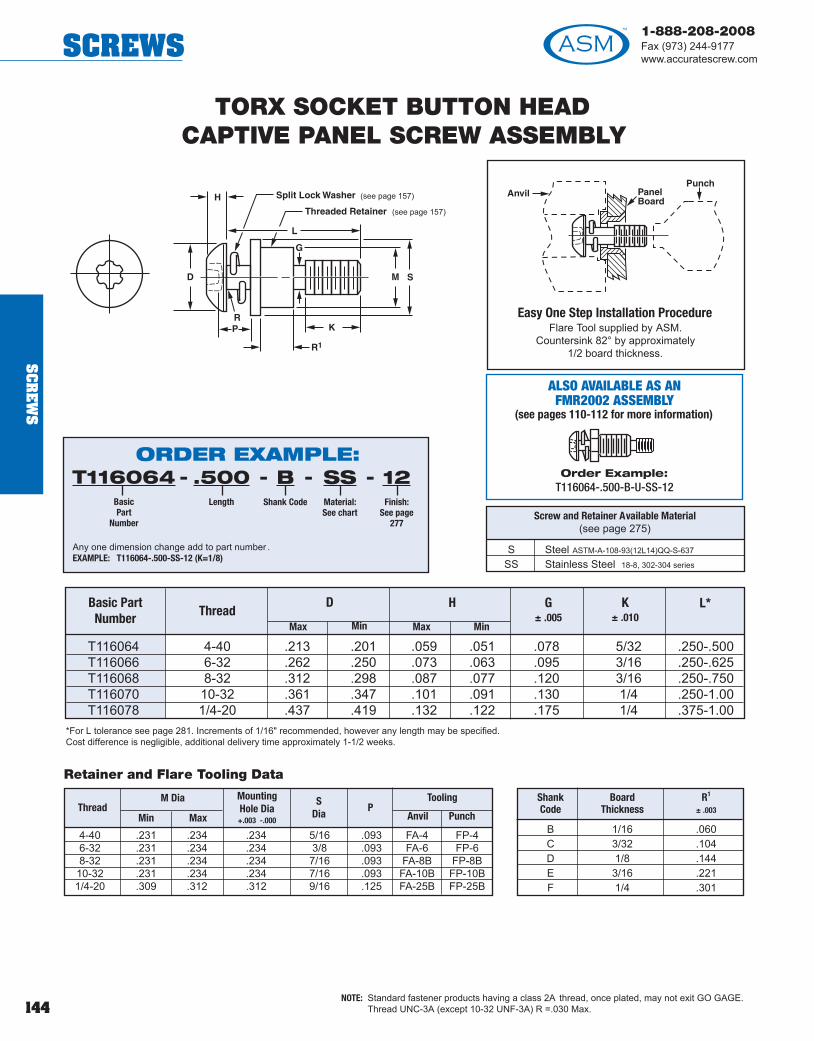
144
1-888-208-2008Fax (973) 244-9177www.accuratescrew.comSCREWS
SC
RE
WS
L
G
TORX SOCKET BUTTON HEADCAPTIVE PANEL SCREW ASSEMBLY
T116064 4-40 .213 .201 .059 .051 .078 5/32 .250-.500T116066 6-32 .262 .250 .073 .063 .095 3/16 .250-.625T116068 8-32 .312 .298 .087 .077 .120 3/16 .250-.750T116070 10-32 .361 .347 .101 .091 .130 1/4 .250-1.00T116078 1/4-20 .437 .419 .132 .122 .175 1/4 .375-1.00
Basic Part Number Thread
Max Max Min
HD G± .005
K± .010
L*
Min
Easy One Step Installation ProcedureFlare Tool supplied by ASM.
Countersink 82° by approximately1/2 board thickness.
*For L tolerance see page 281. Increments of 1/16" recommended, however any length may be specified.Cost difference is negligible, additional delivery time approximately 1-1/2 weeks.
NOTE: Standard fastener products having a class 2A thread, once plated, may not exit GO GAGE.Thread UNC-3A (except 10-32 UNF-3A) R =.030 Max.
4-40 .231 .234 .234 5/16 .093 FA-4 FP-46-32 .231 .234 .234 3/8 .093 FA-6 FP-68-32 .231 .234 .234 7/16 .093 FA-8B FP-8B10-32 .231 .234 .234 7/16 .093 FA-10B FP-10B1/4-20 .309 .312 .312 9/16 .125 FA-25B FP-25B
M Dia
Min Max
MountingHole Dia+.003 -.000
SDia
PTooling
Anvil Punch
Shank Board R1
Code Thickness ± .003
B 1/16 .060C 3/32 .104D 1/8 .144E 3/16 .221F 1/4 .301
Retainer and Flare Tooling Data
Thread
(see page 157)
(see page 157)
S Steel ASTM-A-108-93(12L14)QQ-S-637
SS Stainless Steel 18-8, 302-304 series
Screw and Retainer Available Material(see page 275)
ORDER EXAMPLE:- - -T116064
BasicPart
Number
.500Length
SSMaterial:See chart
12Finish:
See page277
Any one dimension change add to part number .EXAMPLE: T116064-.500-SS-12 (K=1/8)
- BShank Code
ALSO AVAILABLE AS ANFMR2002 ASSEMBLY
(see pages 110-112 for more information)
Order Example:T116064-.500-B-U-SS-12

145
1-888-208-2008Fax (973) 244-9177
www.accuratescrew.com SCREWS
SC
RE
WS
SECURITY SCREW PAN HEAD CAPTIVE18/8 Stainless Steel Only
115050 4-40 .219 .205 .068 .058 5/32 .078 .250-1.5 .22115052 6-32 .270 .256 .082 .072 3/16 .095 .375-3.0 .26115054 8-32 .322 .306 .096 .085 3/16 .120 .500-4.0 .28115056 10-32 .373 .357 .110 .099 1/4 .130 .500-4.0 .36115062 1/4-20 .492 .473 .144 .130 1/4 .175 .500-4.0 .39
BasicPart
NumberThread
Max Min
AHead Diameter
BHead Height
K**± .010
G± .005
L*
Max Min
PK Ref Only
*L +.000-.031 recommended increments of 1/16, however, any length may be specified.Cost difference is negligible, addi ional delivery time approximately 1-1/2 weeks.
Spanner
NOTE: Standard fastener products having a class 2A thread, once plated, may not exit GO GAGE.Thread UNC-3A (except 10-32 UNF-3A) R =.030 Max.
SECURITY SCREW PAN HEAD CAPTIVE ASSEMBLYSplit Lock Washer (G)
See page 157 for details.External Tooth Lock Washer (J)
See page 157 for details.Internal Tooth Lock Washer (H)
See page 157 for details.
ORDER EXAMPLE:115050 - 500 - SS - G - 12
BasicPart
Number
Length Material:See chart
Assy withSplit (G)L’Washerand FlatWasher
Finish:See page
277
ORDER EXAMPLE:115050 - 500 - SS - H - 12
BasicPart
Number
Length Material:See chart
Assy withInternal (H)L’Washerand FlatWasher
Finish:See page
277
ORDER EXAMPLE:115050 - 500 - SS - J - 12
BasicPart
Number
Length Material:See chart
Assy withExternal (J)
L’Washerand FlatWasher
Finish:See page
277
ORDER EXAMPLE:- - -115050
BasicPart
Number
.375Length
SSMaterial:See chart
1Finish:
See page277
To add the Lead Point, add the prefix P to part number.EXAMPLE: P115050-.375- SS-1**Any one dimension change add to part number:EXAMPLE: 115050-.375-SS-1 (K=3/16)

146
1-888-208-2008Fax (973) 244-9177www.accuratescrew.comSCREWS
SC
RE
WS
SECURITY SCREW CAPTIVE - FLAT HEADFor Retainer Washers, see page 147.
Spanner
115068 4-40 .225 .200 .067 .055 5/32 .078 .250-.50115070 6-32 .279 .249 .083 .069 3/16 .095 .375-3.0115072 8-32 .332 .300 .100 .084 3/16 .120 .375-4.0115074 10-32 .385 .348 .116 .098 1/4 .130 .500-4.0115080 1/4-20 .507 .462 .153 .131 1/4 .175 .500-4.0
BasicPart
NumberThread
Max Min
DHead Diameter
HHead Height
K± .010
G± .005
L± 1/32
Max Min
SECURITY SCREW PIN SOCKET - FLAT HEAD
115086 6-32 .307 .263 .097 .013 1/8 3/16 .078 .375-1.0115088 8-32 .359 .311 .112 .014 1/8 3/16 .120 .375-1.5115090 10-32 .411 .359 .127 .015 5/32 1/4 .130 .500-2.0115094 1/4-20 .531 .480 .161 .016 5/32 .1/4 .175 .500-2.0
BasicPart
NumberThread
Max Min
DHead Diameter
HHead Height
K± .010
B± .005
L± 1/32
Max Min
JHex
SocketScrew
115087 6-32 .262 .250 .073 .063 .015 1/8 .044 .250-1.0 3/16 .078115089 8-32 .312 .298 .087 .077 .015 1/8 .052 .375-1.0 3/16 .120115091 10-32 .361 .347 .101 .091 .020 5/32 .070 .250-2.0 1/4 .130115093 1/4-20 .437 .419 .132 .122 .031 5/32 .087 .500-2.0 1/4 .175
BasicPart
NumberThread
Max Min
DHead Diameter
HHead Height
SHeadSide
Height
JHex
SocketSizeMax Min
T Key
Engage-ment
K± .010
B± .005
LLength
SECURITY SCREW SOCKET PIN HEAD - BUTTON
R=.030 Max.
Pin Socket
Pin Socket
18-8StainlessSteel Only
NOTE: Standard fastener products having a class 2A thread, once plated, may not exit GO GAGE.Thread UNC-3A (except 10-32 UNF-3A) R =.030 Max.
NOTE: Standard Fastener products having a class 2A thread, once plated, may not enter 2A GO and NO-GO GAGES.
ORDER EXAMPLE:- - -115068
BasicPart
Number
.500Length
SS18-8
StainlessSteel
1Finish:
See page277
ORDER EXAMPLE:- - -115086
BasicPart
Number
.500Length
SS18-8
StainlessSteel
1Finish:
See page277
ORDER EXAMPLE:- - -115087
BasicPart
Number
.500Length
SS18-8
StainlessSteel
1Finish:
See page277
18-8StainlessSteel Only
18-8StainlessSteel Only
Slight flatand/or
countersunkpermissible
R=.030 Max.
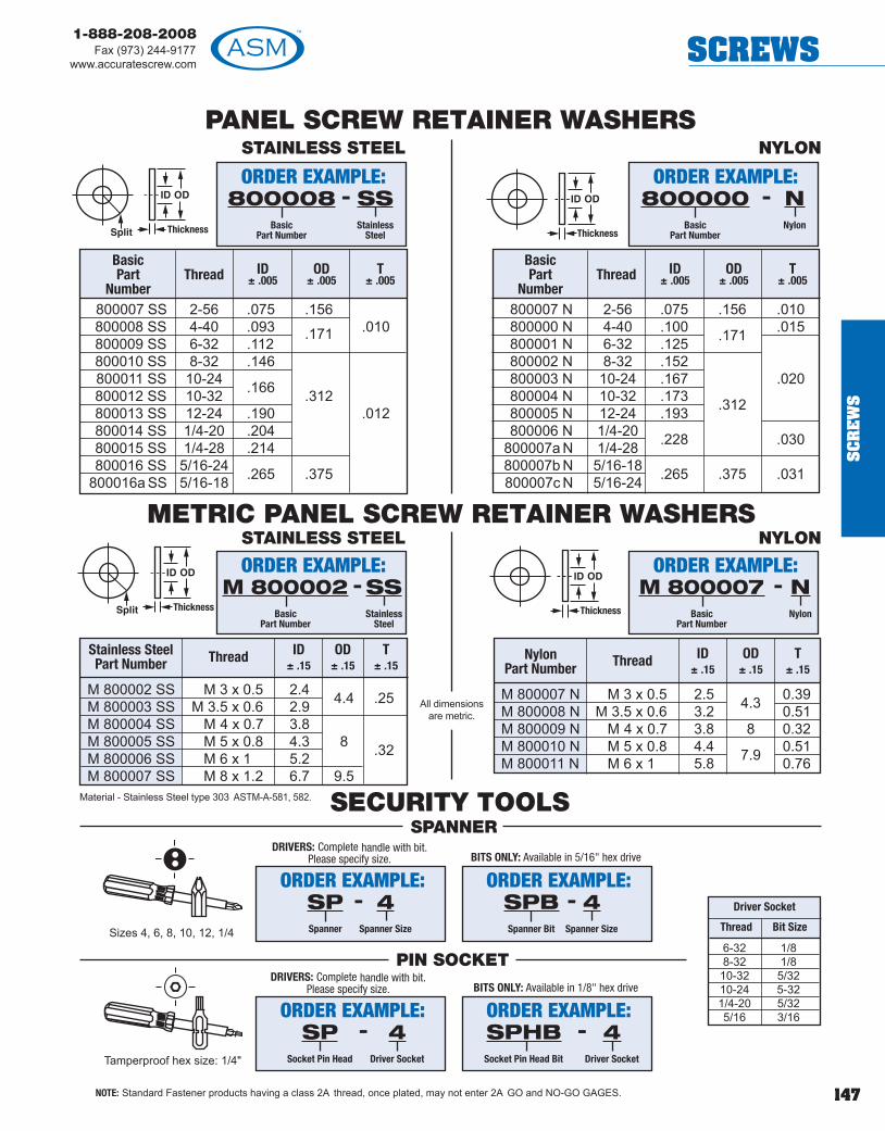
147
1-888-208-2008Fax (973) 244-9177
www.accuratescrew.com SCREWS
SC
RE
WS
SECURITY TOOLS
PANEL SCREW RETAINER WASHERS
METRIC PANEL SCREW RETAINER WASHERS
Sizes 4, 6, 8, 10, 12, 1/4
M 800002 SS M 3 x 0.5 2.4M 800003 SS M 3.5 x 0.6 2.9 4.4 .25
M 800004 SS M 4 x 0.7 3.8M 800005 SS M 5 x 0.8 4.3 8 .32M 800006 SS M 6 x 1 5.2M 800007 SS M 8 x 1.2 6.7 9.5
M 800007 N M 3 x 0.5 2.5 0.39M 800008 N M 3.5 x 0.6 3.2 4.3 0.51M 800009 N M 4 x 0.7 3.8 8 0.32M 800010 N M 5 x 0.8 4.4 7.9 0.51M 800011 N M 6 x 1 5.8 0.76
Stainless SteelPart Number
ID± .15
Thread T± .15
OD± .15
Driver Socket
Thread Bit Size
6-32 1/88-32 1/810-32 5/3210-24 5-321/4-20 5/325/16 3/16
Material - Stainless Steel type 303 ASTM-A-581, 582.
NylonPart Number
ID± .15
Thread T± .15
OD± .15
NOTE: Standard Fastener products having a class 2A thread, once plated, may not enter 2A GO and NO-GO GAGES.
800007 SS 2-56 .075 .156800008 SS 4-40 .093 .010800009 SS 6-32 .112
.171
800010 SS 8-32 .146800011 SS 10-24800012 SS 10-32 .166 .312800013 SS 12-24 .190 .012800014 SS 1/4-20 .204800015 SS 1/4-28 .214800016 SS 5/16-24
800016a SS 5/16-18 .265 .375
BasicPart
NumberThread ID
± .005OD
± .005T
± .005
800007 N 2-56 .075 .156 .010800000 N 4-40 .100 .015800001 N 6-32 .125 .171
800002 N 8-32 .152800003 N 10-24 .167 .020800004 N 10-32 .173 .312800005 N 12-24 .193800006 N 1/4-20
800007a N 1/4-28 .228 .030
800007b N 5/16-18800007c N 5/16-24 .265 .375 .031
BasicPart
NumberThread ID
± .005OD
± .005T
± .005
ORDER EXAMPLE:800008
BasicPart Number
SSStainless
Steel
-ORDER EXAMPLE:
800000Basic
Part Number
NNylon
-
ORDER EXAMPLE:M 800002
BasicPart Number
SSStainless
Steel
-ORDER EXAMPLE:
M 800007Basic
Part Number
NNylon
-
STAINLESS STEEL NYLON
STAINLESS STEEL NYLON
SPANNER
PIN SOCKET
ORDER EXAMPLE:SPSpanner
4Spanner Size
-
BITS ONLY: Available in 5/16" hex driveDRIVERS: Complete handle with bit.
Please specify size.
ORDER EXAMPLE:SPBSpanner Bit
4Spanner Size
-
ORDER EXAMPLE:SP
Socket Pin Head
4Driver Socket
-
BITS ONLY: Available in 1/8" hex driveDRIVERS: Complete handle with bit.
Please specify size.
ORDER EXAMPLE:SPHBSocket Pin Head Bit
4Driver Socket
-Tamperproof hex size: 1/4"
All dimensions are metric.

148
1-888-208-2008Fax (973) 244-9177www.accuratescrew.comSCREWS
SC
RE
WS
METRIC PAN HEAD CAPTIVE PANEL SCREW
Not Avail. M 2 x .4 – – – – – – – – – – – – – – – –1810 M 2.5 x.45 5.0 4.7 1.5 1.3 2.1 1.9 0.6 0.6 2.85 2.52 1.73 1.33 0.70 4.0 1.7 8-201812 M 3 x .5 5.6 5.3 1.8 1.6 2.4 2.2 0.7 0.8 3.06 2.73 1.93 1.56 0.74 5.0 2.0 10-50
Not Avail. M 3.5 x .6 – – – – – – – – – – – – – – – –1814 M 4 x .7 8.0 7.6 2.4 2.2 3.1 2.8 1.0 1.2 4.57 4.24 2.70 2.20 0.93 6.0 2.8 12-801816 M 5 x .8 9.5 9.1 3.0 2.7 3.7 3.4 1.2 1.2 5.07 4.74 3.20 2.70 1.0 6.0 3.7 12-801818 M 6 x 1.0 12.0 11.5 3.6 3.3 4.6 4.3 1.4 1.6 7.09 6.76 4.06 3.56 1.14 8.0 4.2 16-100
BasicPart
Number
Thread and
Pitch
AHead Dia
Head Height Slot Recess
T Depth N Width
K± .25
mm
L*Nom
Lengthmm
E DiaG
± .12
mm
METRIC PAN HEAD CAPTIVE PANEL SCREW ASSEMBLY
*L ±1 5 mm recommended increments of even number mm however , any length may be specified.
NOTE: Standard fastener products having a class 2A thread, once plated, may not exit GO GAGE.Fastener after captivation may not accept GO GAGE on last inside thread.
External Tooth Lock Washer (E)See page 157 for details.
Split Lock Washer (S)See page 157 for details.
Internal Tooth Lock Washer (I)See page 157 for details.
Pan Head Captive Panel ScrewSlotted (PS) or Phillips (PP)
B Brass, Type M558S Carbon Steel property class 8.8
SS Stainless Steel, 18-8
Available Material (see page 275)
Max Min Max Min Max Min Max Min Max Min Max Min
BSlotted
B1
PhillipsC
DepthJ
Width
ORDER EXAMPLE:1810
BasicPart
Number
8Lengthin mm
SSMaterial:See chart
PSHead Style:Slotted (PS)
or Phillips (PP)
-- 12Finish:
See page277
- -
Any one dimension change add to part number:EXAMPLE: 1810-8-SS-PS-12 (K=4.5)All dimensions in millimeters.
ORDER EXAMPLE:1810
BasicPart
Number
8Lengthin mm
SSMaterial:See chart
PSPan Head
Slotted (PS)or Phillips (PP)
-- 12Finish:
See page277
- SAssemblyw/Split (S)L’Washer
& Flat Washer
- -ORDER EXAMPLE:
1810BasicPart
Number
8Lengthin mm
SSMaterial:See chart
PSPan Head
Slotted (PS)or Phillips (PP)
-- 12Finish:
See page277
- IAssembly
w/Internal (I)L’Washer
& Flat Washer
- -
ORDER EXAMPLE:1810
BasicPart
Number
8Lengthin mm
SSMaterial:See chart
PSPan Head
Slotted (PS)or Phillips (PP)
-- 12Finish:
See page277
- EAssembly
w/External (E)L’Washer
& Flat Washer
- -

149
1-888-208-2008Fax (973) 244-9177
www.accuratescrew.com SCREWS
SC
RE
WS
METRIC PAN HEAD CAPTIVE PANEL SCREW ASSEMBLY
Easy One Step Installation Procedure(typical for all assemblies)
Flare tool supplied by ASM. Countersink 82°by approximately 1/2 board thickness.
*L ± 1.5 mm recommended increments of even number mm however , any leng h may be specified.
All dimensions are in millimeters.
Shank BoardR
1± .003Code Thickness
A 1/32 .027B 1/16 .060C 3/32 .104D 1/8 .144E 3/16 .221F 1/4 .301
Retainer and Flare Tooling DataAll dimensions are in inches.
(see page 157 for details)
Specify S for Split Lock Washer assembly
B Brass, Type M558S Carbon Steel property class 8.8
SS Stainless Steel, 18-8
Screw Available Material
B Brass QQ B-626 Comp 360 1/2 Hard ASTMB-16
S Steel ASTM-A-108, QQ-S-637(12L14)SS Stainless Steel, ASTM-A-581, A-582
(Non-magnetic) 303 series
Retainer Available Material
M 2 x .4 – – – – – – –Not Avail.M 2.5 x 4.5 .175 .178 .178 .375 .062 MA2.5 MP2.5M 3 x .5 .197 .200 .200 .437 .060 MA3 MP3M 3.5 x 6 – – – – – – –Not Avail.M 4 x .7 .237 .240 .240 .531 .093 MA4 MP4M 5 x .8 .278 .281 .281 .625 .093 MA5 MP5M 6 x 1.0 .318 .321 .321 .625 .125 MA6 MP6
Thread M Dia
Min Max
MountingHole Dia
+.003 -.000
SDia P
Tooling
Anvil Punch
Not Avail. M 2 x .4 – – – – – – – – – – – – – – – –1810 M 2.5 x.45 5.0 4.7 1.5 1.3 2.1 1.9 0.6 0.7 2.85 2.46 1.78 1.38 0.70 4.0 1.7 8-201812 M 3 x .5 5.6 5.3 1.8 1.6 2.4 2.2 0.7 0.8 3.06 2.30 1.96 1.56 0.74 5.0 2.0 10-50
Not Avail. M 3.5 x .6 – – – – – – – – – – – – – – – –1814 M 4 x .7 9.5 7.6 2.4 2.2 3.1 2.8 1.0 1.2 4.57 4.20 2.76 2.31 0.93 6.0 2.8 12-801816 M 5 x .8 10.0 9.1 3.0 2.7 3.7 3.4 1.2 1.2 5.07 4.71 3.20 2.70 1.00 6.0 3.7 12-801818 M 6 x 1.0 12.0 11.5 3.6 3.3 4.6 4.3 1.4 1.6 7.09 6.64 4.07 3.62 1.14 8.0 4.2 16-100
BasicPart
Number
Thread and
Pitch
AHead Dia
Head Height Slot Recess
T Depth N Width
nom
K± .25
mm
L*Nom
Lengthmm
E DiaG
± .12
mmMax Min Max Min Max Min Max Min Max Min Max Min
BSlotted
B1
PhillipsC
DepthJ
Width
ORDER EXAMPLE:1810
BasicPart
Number
8Lengthin mm
SSMaterial:See chart
PSPan Head
Slotted (PS)or Phillips (PP)
-- 12Finish:
See page277
- EWasher Type:See page 157
- -BShank Code:
See chartbelow
-
Any one dimension change add to part number . EXAMPLE: 1810-8-SS-E-12 (K-4.5)
NOTE: Standard fastener products having a class 2A thread, once plated, may not exit GO GAGE.Fastener after captivation may not accept GO GAGE on last inside thread.

150
1-888-208-2008Fax (973) 244-9177www.accuratescrew.comSCREWS
SC
RE
WS
1820 M 2 x .4 3.8 1.3 .85 0.5 4.0 1.2 8-301821 M 2.5 x.45 4.5 1.6 1.00 0.6 4.0 1.7 8-301822 M 3 x .5 5.5 2 1.30 0.8 5.0 2.0 10-601823 M 3.5 x .6 6.0 2.4 1.40 0.8 5.0 2.3 10-351824 M 4 x .7 7.0 2.6 1.60 1.0 6.0 2.8 12-801825 M 5 x .8 8.5 3.3 2.00 1.2 6.0 3.7 12-1001826 M 6 x 1.0 10.0 3.9 2.30 1.2 8.0 4.2 16-100
METRIC CHEESE HEAD CAPTIVE PANELSCREW ASSEMBLY
METRIC CHEESE HEAD CAPTIVE PANEL SCREW
External Tooth Lock Washer (E)See page 157 for details
Split Lock Washer (S)See page 157 for details
Internal Tooth Lock Washer (I)See page 157 for details
Slotted
*L ± 1.5 mm recommended increments of even number mm however , any leng h may be specified.
B Brass, Type M558S Carbon Steel 4.8
SS Stainless Steel, 18-8
Available Material (see page 275)
ORDER EXAMPLE:1820
BasicPart
Number
8Lengthin mm
SSMaterial:See chart
-- 12Finish:
See page277
-
Any one dimension change add to part number:EXAMPLE: 1820-8-SS-12 (K=4.5)All dimensions are in millimeters
ORDER EXAMPLE:1820
BasicPart
Number
8Lengthin mm
SSMaterial:See chart
-- 12Finish:
See page277
- SAssemblyw/Split (S)L’Washer
& Flat Washer
-
BasicPart
Number
Thread and
Pitch
AHead Dia
Nom
BHead
Height
CSlot Depth
Max
JSlot Width
Nom
K± .25 mm
G± .12 mm
L*Nom Length
in mm
To order Captive Washer only, prefix part number with W. EXAMPLE: W1820
ORDER EXAMPLE:1820
BasicPart
Number
8Lengthin mm
SSMaterial:See chart
-- 12Finish:
See page277
- IAssembly
w/Internal (I)L’Washer
& Flat Washer
-
To order Captive Washer only, prefix part number with W. EXAMPLE: W1820
ORDER EXAMPLE:1820
BasicPart
Number
8Lengthin mm
SSMaterial:See chart
-- 12Finish:
See page277
- EAssembly
w/External (E)L’Washer
& Flat Washer
-
To order Captive Washer only, prefix part number with W. EXAMPLE: W1820
NOTE: Standard fastener products having a class 2A thread, once plated, may not exit GO GAGE.Fastener after captivation may not accept GO GAGE on last inside thread.

151
1-888-208-2008Fax (973) 244-9177
www.accuratescrew.com SCREWS
SC
RE
WS
METRIC CHEESE HEAD CAPTIVE PANEL SCREW ASSEMBLY
Easy One Step Installation Procedure(typical for all assemblies)
Flare tool supplied by ASM. Countersink 82°by approximately 1/2 board thickness.
*L ±1.5 mm recommended increments of even number mm however , any length may be specified.
(see page 157)
M 2x.4 .153 .156 .156 .312 .062 MA 2 MP 2M 2.5x.45 .175 .178 .178 .375 .062 MA 2.5 MP 2.5M 3x.5 .197 .200 .200 .437 .060 MA3 MP3M 3.5x6 .215 .218 .218 .437 .093 MA 3.5 MP 3.5M 4x.7 .237 .240 .240 .531 .093 MA4 MP4M 5x.8 .278 .281 .281 .625 .093 MA5 MP5M 6x1.0 .318 .321 .321 .625 .125 MA6 MP6
Shank BoardCode Thickness
A 1/32 .027B 1/16 .060C 3/32 .104D 1/8 .144E 3/16 .221F 1/4 .301
Thread M Dia
Min Max
MountingHole Dia
+.003 -.000
SDia
P Tooling
Anvil Punch
Retainer and Flare Tooling DataAll dimensions are in inches.
Specify “S” forSplit Lock Washer
Specify “E” forExternal Tooth Lock Washer
Specify “I” forInternal Tooth Lock Washer
R1
± .003
ORDER EXAMPLE:1820
BasicPart
Number
8Lengthin mm
SSMaterial:See chart
-- 1Finish:
See page277
EWasher Type:See page 157
- -BShankCode
-
Any one dimension change add to part number . EXAMPLE: 1820-8-SS-12 (K=4.5)
1820 M 2 x .4 3.8 1.3 .85 0.5 4.0 1.2 8-301821 M 2.5 x .45 4.5 1.6 1.00 0.6 4.0 1.7 8-301822 M 3 x .5 5.5 2.0 1.30 0.8 5.0 2.0 10-601823 M 3.5 x .6 6.0 2.4 1.40 0.8 5.0 2.3 10-351824 M 4 x .7 7.0 2.6 1.60 1.0 6.0 2.8 12-801825 M 5 x .8 8.5 3.3 2.00 1.2 6.0 3.7 12-1001826 M 6 x 1.0 10.0 3.9 2.30 1.2 8.0 4.2 16-100
BasicPart
Number
Thread and
Pitch
AHead Dia
Nom
BHead
Height
CSlot Depth
Max
JSlot Width
Nom
K± .25 mm
G± .12 mm
L*Nom Length
in mm
All dimensions in millimeters
NOTE: Standard fastener products having a class 2A thread, once plated, may not exit GO GAGE.Fastener after captivation may not accept GO GAGE on last inside thread.

152
1-888-208-2008Fax (973) 244-9177www.accuratescrew.comSCREWS
SC
RE
WS
All dimensions are in millimeters.
METRIC CAPTIVE SOCKET HEAD CAP SCREWFor Retainer Washers see page 147.
Not Avail M 2 x .4 – – – – –Not Avail M 2.5 x .45 – – – – –
1830 M 3 x .5 5.5 3.0 4.0 2.0 8-30Not Avail M 3.5 x .6 – – – – –
1832 M 4 x .7 7.0 4.0 4.0 2.8 8-501834 M 5 x .8 8.5 5.0 4.0 3.7 8-701836 M 6 x 1.0 10.0 6.0 6.0 4.2 8-1201838 M 8 x 1.25 13.0 8.0 8.0 6.0 8-120
BasicPart
Number
Thread and
Pitch
DMax
B± .12 mm
L Length*(even number
mm only)
HMax
K± .25 mm
*L ±1.5 mm recommended increments of even number mm however , any length may be specified.
METRIC CAPTIVE SOCKET HEAD CAPSCREW ASSEMBLY
External Tooth Lock Washer (E)See page 157 for details.
Split Lock Washer (S)See page 157 for details.
Internal Tooth Lock Washer (I)See page 157 for details.
B Brass, Type M558S ASTM-A-108-93
(12L14) QQ-S-637
SS Stainless Steel, 18-8
Available Material(see page 275)
ORDER EXAMPLE:1830
BasicPart
Number
8Lengthin mm
SSMaterial:See chart
-- 12Finish:
See page277
-
Any one dimension change add to part number:EXAMPLE: 1830-8-SS-12 (K=4.5)
ORDER EXAMPLE:1830
BasicPart
Number
8Lengthin mm
SSMaterial:See chart
-- 12Finish:
See page277
- SAssemblyw/Split (S)L’Washer
& Flat Washer
-ORDER EXAMPLE:
1830BasicPart
Number
8Lengthin mm
SSMaterial:See chart
-- 12Finish:
See page277
- IAssembly
w/Internal (I)L’Washer
& Flat Washer
-
ORDER EXAMPLE:1830
BasicPart
Number
8Lengthin mm
SSMaterial:See chart
-- 12Finish:
See page277
- EAssembly
w/External (E)L’Washer
& Flat Washer
-
NOTE: Standard fastener products having a class 2A thread, once plated, may not exit GO GAGE.Fastener after captivation may not accept GO GAGE on last inside thread.

153
1-888-208-2008Fax (973) 244-9177
www.accuratescrew.com SCREWS
SC
RE
WS
METRIC CAPTIVE SOCKET HEAD CAP SCREW ASSEMBLY
Easy One Step Installation Procedure(typical for all assemblies)
Flare tool supplied by ASM. Countersink 82°by approximately 1/2 board thickness.
*L ±1.5 mm recommended increments of even number mm however , any length may be specified.
All dimensions are in millimeters.
Retainer and Flare Tooling DataAll Dimensions are in inches.
(see page 157 for details)
S ASTM-A-108-93(12L14) QQ-S-637
SS Stainless Steel, 18-8
Screw Available Material
B Brass QQ-B-626 Comp360 1/2 HardASTMB-16
S ASTM-A-108-93(12L14) QQ-S-637
SS Stainless Steel ASTM-A-581,A582 (Non-Magnetic)303 series
Retainer Available Material
Not Avail M 2 x .4 – – – – –Not Avail M 2.5 x .45 – – – – –
1830 M 3 x .5 5.5 3.0 4.0 2.0 8-30Not Avail M 3.5 x .6 – – – – –
1832 M 4 x .7 7.0 4.0 4.0 2.8 8-501834 M 5 x .8 8.5 5.0 4.0 3.7 8-701836 M 6 x 1.0 10.0 6.0 6.0 4.2 8-120
BasicPart
Number
Thread and
Pitch
DMax
B± .12 mm
L Length*(even number
mm only)
HMax
K± .25 mm
Shank BoardCode Thickness
A 1/32 .027B 1/16 .060C 3/32 .104D 1/8 .144E 3/16 .221F 1/4 .301
R1
± .003
Specify “S” forSplit Lock Washer
Specify “E” forExternal Tooth Lock Washer
Specify “I” forInternal Tooth Lock Washer
ORDER EXAMPLE:1830
BasicPart
Number
8Lengthin mm
SSMaterial:See chart
-- 12Finish:
See page277
EWasher Type:See page 157
- -BShankCode
-
Any one dimension change add to part number . EXAMPLE: 1820-8-SS-12 (K=4.5)
M2x.4 – – – – – – –Not AvailM2.5x4.5 – – – – – – –Not AvailM3x.5 .197 .200 .200 .437 .060 MA3 MP3M3.5x6 – – – – – – –Not AvailM4x.7 .237 .240 .240 .531 .093 MA4 MP4M5x.8 .278 .281 .281 .625 .093 MA5 MP5M6x1.0 .318 .321 .321 .625 .125 MA6 MP6
Thread M Dia
Min Max
MountingHole Dia
+.003 -.000
SDia
P Tooling
Anvil Punch
NOTE: Standard fastener products having a class 2A thread, once plated, may not exit GO GAGE.Fastener after captivation may not accept GO GAGE on last inside thread.

154
1-888-208-2008Fax (973) 244-9177www.accuratescrew.comSCREWS
SC
RE
WS
METRIC HEX HEAD CAPTIVE MACHINE SCREWFor Retainer Washers see page 147.
Not Avail M 2x.4 – – – – – – –Not Avail M 2.5x.45 – – – – – – –
1840 M 3x.5 5.32 5.5 1.88 2.21 5.0 2.0 10-30Not Avail M 3.5x.6 – – – – – – –
1842 M 4x.7 6.78 7.0 2.68 2.92 6.0 2.8 12-501844 M 5x.8 7.78 8.0 3.35 3.65 6.0 3.7 12-601846 M 6x1.0 9.78 10.0 3.85 4.15 8.0 4.2 16-100
BasicPart
Number
Thread and
Pitch
D
Min Max
B± .12 mm
L Length*(even number
mm only)
H
Min Max
K± .25 mm
METRIC HEX HEAD CAPTIVE MACHINESCREW ASSEMBLY
All dimensions are in millimeters.
External Tooth Lock Washer (E)See page 157 for details.
Split Lock Washer (S)See page 157 for details.
Internal Tooth Lock Washer (I)See page 157 for details.
*L ±1.5 mm recommended increments of even number mm however , any length may be specified.
B Brass, Type M558S ASTM-A-108-93
(12L14) QQ-S-637
SS Stainless Steel, 18-8
Available Material(see page 275)
ORDER EXAMPLE:1840
BasicPart
Number
10Lengthin mm
SSMaterial:See chart
-- 12Finish:
See page277
-
Slotted Hex Head, add SDS to part number.EXAMPLE: 1840-10-SS-SDS-12
ORDER EXAMPLE:1840
BasicPart
Number
10Lengthin mm
SSMaterial:See chart
-- 12Finish:
See page277
- SAssemblyw/Split (S)L’Washer
& Flat Washer
-ORDER EXAMPLE:
1840BasicPart
Number
10Lengthin mm
SSMaterial:See chart
-- 12Finish:
See page277
- IAssembly
w/Internal (I)L’Washer
& Flat Washer
-
ORDER EXAMPLE:1840
BasicPart
Number
10Lengthin mm
SSMaterial:See chart
-- 12Finish:
See page277
- EAssembly
w/External (E)L’Washer
& Flat Washer
-
NOTE: Standard fastener products having a class 2A thread, once plated, may not exit GO GAGE.Fastener after captivation may not accept GO GAGE on last inside thread.
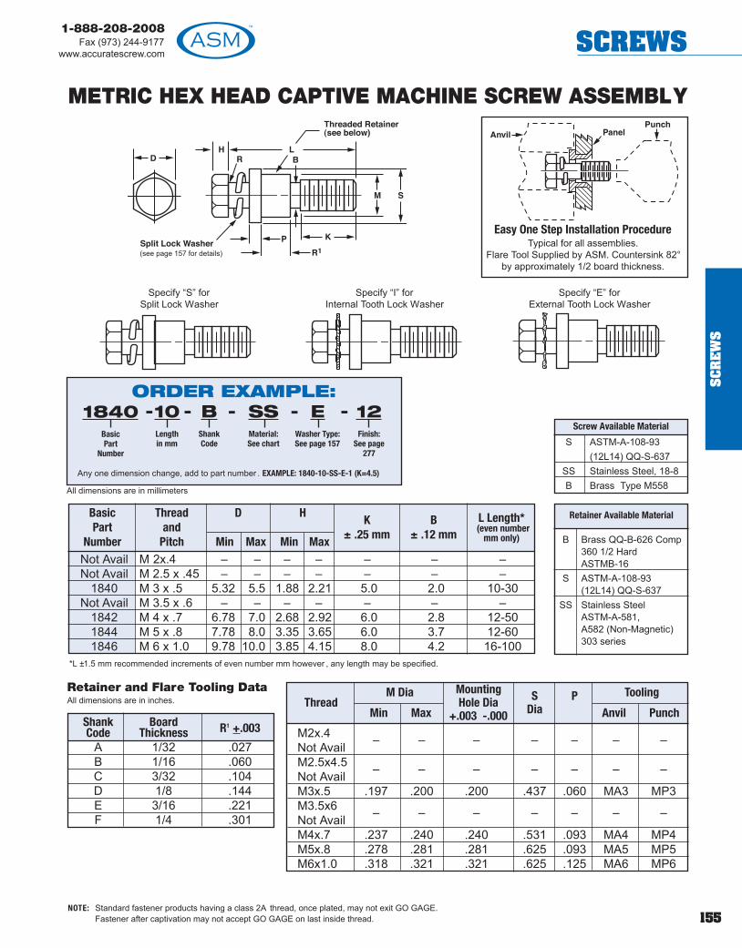
155
1-888-208-2008Fax (973) 244-9177
www.accuratescrew.com SCREWS
SC
RE
WS
METRIC HEX HEAD CAPTIVE MACHINE SCREW ASSEMBLY
*L ±1.5 mm recommended increments of even number mm however , any length may be specified.
All dimensions are in millimeters
Easy One Step Installation ProcedureTypical for all assemblies.
Flare Tool Supplied by ASM. Countersink 82°by approximately 1/2 board thickness.
(see page 157 for details)
S ASTM-A-108-93(12L14) QQ-S-637
SS Stainless Steel, 18-8B Brass Type M558
Screw Available Material
Not Avail M 2x.4 – – – – – – –Not Avail M 2.5 x .45 – – – – – – –
1840 M 3 x .5 5.32 5.5 1.88 2.21 5.0 2.0 10-30Not Avail M 3.5 x .6 – – – – – – –
1842 M 4 x .7 6.78 7.0 2.68 2.92 6.0 2.8 12-501844 M 5 x .8 7.78 8.0 3.35 3.65 6.0 3.7 12-601846 M 6 x 1.0 9.78 10.0 3.85 4.15 8.0 4.2 16-100
BasicPart
Number
Thread and
Pitch
D
Min Max
B± .12 mm
L Length*(even number
mm only)
H
Min Max
K± .25 mm
Shank Board R1 +.003Code ThicknessA 1/32 .027B 1/16 .060C 3/32 .104D 1/8 .144E 3/16 .221F 1/4 .301
Retainer and Flare Tooling DataAll dimensions are in inches.
Specify “S” forSplit Lock Washer
Specify “E” forExternal Tooth Lock Washer
Specify “I” forInternal Tooth Lock Washer
B Brass QQ-B-626 Comp360 1/2 HardASTMB-16
S ASTM-A-108-93(12L14) QQ-S-637
SS Stainless Steel ASTM-A-581,A582 (Non-Magnetic)303 series
Retainer Available Material
ORDER EXAMPLE:1840
BasicPart
Number
10Lengthin mm
SSMaterial:See chart
-- 12Finish:
See page277
EWasher Type:See page 157
- -BShankCode
-
Any one dimension change, add to part number . EXAMPLE: 1840-10-SS-E-1 (K=4.5)
M2x.4 – – – – – – –Not AvailM2.5x4.5 – – – – – – –Not AvailM3x.5 .197 .200 .200 .437 .060 MA3 MP3M3.5x6 – – – – – – –Not AvailM4x.7 .237 .240 .240 .531 .093 MA4 MP4M5x.8 .278 .281 .281 .625 .093 MA5 MP5M6x1.0 .318 .321 .321 .625 .125 MA6 MP6
Thread M Dia
Min Max
MountingHole Dia
+.003 -.000
SDia
P Tooling
Anvil Punch
NOTE: Standard fastener products having a class 2A thread, once plated, may not exit GO GAGE.Fastener after captivation may not accept GO GAGE on last inside thread.

156
1-888-208-2008Fax (973) 244-9177www.accuratescrew.comSCREWS
SC
RE
WS
METRIC FLAT HEAD CROSS-RECESSEDCAPTIVE MACHINE SCREW
For Retainer Washers, see page 147.
1850 M 2x.4 3.8 1.2 4.0 1.2 8-201852 M 2.5x.45 4.7 1.5 4.0 1.7 8-201854 M 3x.5 5.6 1.65 5.0 2.0 10-50
Not Avail M 3.5x.6 – – – – –1856 M 4x.7 7.5 2.2 6.0 2.8 12-801858 M 5x.8 9.2 2.5 6.0 3.7 12-801859 M 6x1.0 11.0 3.0 8.0 4.2 16-80
BasicPart
Number
Thread and
Pitch
DHeadDia
B± .12 mm
L*(even number
mm only)
HMax
K± .25 mm
All dimensions are in millimeters
*L ±1.5 mm recommendedincrements of even number mmhowever, any length may bespecified.
1860 M 2x.4 3.8 1.2 0.5 0.6 4.0 1.2 8-301862 M 2.5x.45 4.7 1.5 0.6 0.75 4.0 1.7 8-301864 M 3x.5 5.5 1.65 0.8 0.85 5.0 2.0 10-50
Not Avail M 3.5x.6 – – – – – – –1866 M 4x.7 8.4 2.7 1.2 1.3 6.0 2.8 12-801868 M 5x.8 9.3 2.7 1.2 1.4 6.0 3.7 12-801869 M 6x1.0 11.3 3.3 1.6 1.6 8.0 4.2 16-80
BasicPart
Number
Thread and
Pitch
DHeadDia
B± .12
L*(even number
mm only)
HMax
K± .25
*L ±1.5 mm recommended increments of even number mm however , any length may be specified.
All dimensions are in millimeters.
JSlot Width
Nom
TSlot Depth
Max
B Brass, Type M558S Carbon Steel
property class 4.8SS Stainless Steel, 18-8
Available Material(see page 275)
METRIC FLAT HEAD SLOTTEDCAPTIVE MACHINE SCREW
ORDER EXAMPLE:1850
BasicPart
Number
8Lengthin mm
SSMaterial:See chart
-- 12Finish:
See page277
-
Change any one dimension, add to part number . EXAMPLE: 1850-8-SS-12 (K=4.5)
ORDER EXAMPLE:1860
BasicPart
Number
8Lengthin mm
SSMaterial:See chart
-- 12Finish:
See page277
-
Change any one dimension, add to part number . EXAMPLE: 1860-8-SS-12 (K=4.5)
B Brass, Type M558S Carbon Steel property class 4.8
SS Stainless Steel, 18-8
Available Material (see page 275)
NOTE: Standard fastener products having a class 2A thread, once plated, may not exit GO GAGE.Fastener after captivation may not accept GO GAGE on last inside thread.

157
1-888-208-2008Fax (973) 244-9177
www.accuratescrew.com SCREWS
SC
RE
WS
Internal Tooth Lock Washers
903133 2 .175 .200 .089 .095 .010 .015903135 4 .255 .270 .115 .123 .015 .019903137 6 .275 .295 .141 .150 .017 .021903139 8 .325 .340 .168 .176 .018 .023903141 10 .365 .381 .195 .204 .020 .025903143 1/4 .460 .478 .256 .267 .023 .028903145 5/16 .594 .610 .320 .332 .028 .034903147 3/8 .670 .694 .384 .398 .032 .040903149 7/16 .740 .789 .448 .464 .032 .040
BasicPart
Number
NormalWasher
Size
A OD
Min Max
B ID
Min Max
C Thickness
Min Max
External Tooth Lock Washers
Split Lock Washers
*American Standard washer width is a pproximate.
S Spring Steel HRC 42-47SS Stainless Steel, Type 304
Metric Available Material (see page 275)
S Spring Steel HRC 42-47SS Stainless Steel, Type 304
Metric Available Material (see page 275)
S Spring Steel HRC 44-51SS Stainless Steel, Type 304 or 316
Metric Available Material (see page 275)
S Spring Steel HRC 42-47SS Stainless Steel, Type 304B Phosphorus Bronze conforming to
ASM B159 Copper Alloy No. 510
American Standard Available Material (see page 275)
903180 M2 4.40 4.70 2.25 2.40 .25 .35903181 M2.5 5.35 5.45 2.65 2.80 .25 .35903183 M3 6.85 7.35 3.15 3.30 .35 .50903184 M3.5 7.55 8.05 3.65 3.80 .40 .55903185 M4 8.25 8.75 4.15 4.30 .45 .60903186 M5 10.00 10.50 5.15 5.30 .55 .70903187 M6 12.20 12.95 6.20 6.50 .55 .70
BasicPart
Number
NormalWasher
Size
A OD
Min Max
B ID
Min Max
C Thickness
Min Max
Not Avail. 2 – – – – – –903132 4 .245 .260 .115 .123 .015 .019903134 6 .305 .320 .141 .150 .016 .022903136 8 .365 .381 .168 .176 .018 .023903138 10 .395 .410 .195 .204 .020 .025903140 12 .460 .475 .221 .231 .023 .028903142 1/4 .494 .510 .256 .267 .023 .028903144 5/16 .588 .610 .320 .332 .028 .034903146 3/8 .670 .694 .384 .398 .032 .040903148 7/16 .740 .760 .448 .464 .032 .040
BasicPart
Number
NormalWasher
Size
A OD
Min Max
B ID
Min Max
C Thickness
Min Max
903188 M2 – – 2.25 2.40 .25 .35903189 M2.5 5.45 5.85 2.65 2.80 .25 .35903190 M3 6.85 7.35 3.15 3.30 .35 .50903191 M3.5 7.55 8.05 3.65 3.80 .40 .55903192 M4 8.50 9.00 4.15 4.30 .45 .60903193 M5 10.00 10.50 5.15 5.30 .50 .65903194 M6 12.20 12.95 6.20 6.50 .55 .70
BasicPart
Number
NormalWasher
Size
A OD
Min Max
B ID
Min Max
C Thickness
Min Max
903150 2 .172 .088 .094 .035 .020903152 4 .209 .115 .121 .040 .025903154 5 .236 .128 .134 .047 .031903156 6 .250 .141 .148 .047 .031903158 8 .293 .168 .175 .055 .040903160 10 .334 .194 .202 .062 .047903162 12 .377 .221 .229 .070 .056903164 1/4 .489 .255 .263 .109 .062903166 5/16 .586 .318 .328 .125 .078903168 3/8 .683 .382 .393 .141 .094903170 7/16 .779 .446 .459 .156 .109
BasicPart
Number
NormalWasher
Size
A OD
Max2
B ID
Min Max
W C Washer Section
Width* ThicknessApprox.
903195 M2 4.4 2.1 .5903196 M2.5 5.1 2.6 .6903197 M3 6.2 3.1 .8903198 M3.5 6.7 3.6 .8903199 M4 7.6 4.1 .9903200 M5 9.2 5.1 1.2903201 M6 11.8 6.1 1.6
BasicPart
Number
ScrewDia
A OD
B ID
C Thickness
LOCK WASHERS
METRIC
STANDARD
METRIC
STANDARD
METRIC
STANDARD
S Steel (1008)SS Stainless Steel (18-8)B Silicone Bronze conforming to
ASM B99 Copper Alloy 651 or 655
American Standard Available Material (see page 275)
S Spring Steel HRC 42-47SS Stainless Steel, Type 304B Phosphorus Bronze conforming to
ASM B159 Copper Alloy No. 510
American Standard Available Material (see page 275)
ORDER EXAMPLE:903133
BasicPart Number
32Finish:
See page 277
-SMaterial:See chart
-

158
1-888-208-2008Fax (973) 244-9177www.accuratescrew.comSCREWS
17000 1/8 .125017002 .187517004 .250017006 .312517008 .375017012 .437017009 .500017169 .625017170 .750017171 .875017172 1.000017011 .125017013 .187517015 .250017017 .312517001 .375017027 .437517029 .500017003 .562517033 .625017035 .687517037 .750017173 .875017174 1.000017175 1.250017176 1.500017010 .125017005 .187517014 .250017016 .312517018 .375017019 .437017020 .500017021 .562517022 .625017023 .687517024 .750017025 .8750
SLOTTED HEAD SHOULDER SCREW
A +.000-.001
B +.002-.000
C DBasicPart
Number
E F
Screw Driver Slot
G +.015 W +.015
NOTE: This product also available with the Self-Locking Device, see page 109. Tolerance A & B +.005 unless otherwise specified.
1/8.1245
5/32.1562
3/16.1870
1/4
1/8
#4-40 5/32
9/32
5/16 5/32 #8-32
3/16
A AluminumB BrassN* NylonS Steel
SS Stainless SteelD* Delrin
Available Material (see page 275)
#6-32
1/83/161/45/163/87/161/25/83/47/81
1/83/161/45/163/87/161/29/165/8
11/163/47/81
1-1/41-1/21/83/161/45/163/87/161/29/165/8
11/163/47/8
.062 .062
*Nylon and Delrin tolerance A and B = ± .002
ORDER EXAMPLE:17000
BasicPart
Number
SLDSelf-Locking
Device Option:See page 109
SSMaterial:See chart
-- 12Finish:
See page277
-
SC
RE
WS
! TECHTIPTolerances onfractions arelarger thantoleranceson decimals.

159
1-888-208-2008Fax (973) 244-9177
www.accuratescrew.com SCREWS
17026 1.000017028 1.250017031 1.37517030 1.500017177 1.625017178 1.750017180 2.000017032 .125017034 .187517036 .250017038 .312517040 .375017041 .437017042 .500017043 .562517044 .625017045 .687517046 .750017047 .875017048 1.000017050 1.250017051 1.37517052 1.500017181 1.625017182 1.750017183 2.000017054 .2505 1/2 7/1617100 .2505 7/16 3/817056 .3125 1/2 7/1617102 .3125 7/16 3/817058 .3750 1/2 7/1617104 .3750 7/16 3/817060 .5000 1/2 7/1617106 .5000 7/16 3/817061 .5625 1/2 7/1617108 .5625 7/16 3/817062 .6250 1/2 7/1617110 .6250 7/16 3/8
SLOTTED HEAD SHOULDER SCREW
A +.000-.001
B +.002-.000
C DBasicPart
Number
E F
3/16.1870
1/4.2495
5/16 5/32 #8-32 3/16
3/8 3/16 #10-32
7/32 1/4-20
1/4
11-1/41-3/81-1/21-5/81-3/4
21/83/161/45/163/87/161/29/165/8
11/163/47/81
1-1/41-3/81-1/21-5/81-3/4
2
NOTE: This product also available with the Self-Locking Device, see page 109. Tolerance A & B +.005 unless otherwise specified.
5/16.3120
ORDER EXAMPLE:17026
BasicPart
Number
SLDSelf-Locking
Device Option:See page 109
SSMaterial:See chart
-- 12Finish:
See page277
-
Screw Driver SlotG +.015 W +.015
A AluminumB BrassN* NylonS Steel
SS Stainless SteelD* Delrin
Available Material (see page 275)
.062 .062
*Nylon and Delrin tolerance A and B = ± .002 SC
RE
WS
! TECHTIPStraight ordiamond knurlcan be appliedto most screwhead styles.

160
1-888-208-2008Fax (973) 244-9177www.accuratescrew.comSCREWS
SLOTTED HEAD SHOULDER SCREW
17063 .6875 1/2 7/1617112 .6875 7/16 3/817064 .7500 1/2 7/1617114 .7500 7/16 3/817065 .8750 1/2 7/1617116 .8750 7/16 3/817089 1.0000 1/2 7/1617118 1.0000 7/16 3/817184 1.2500 1/2 7/1617185 1.5000 7/16 3/817186 1.7500 1/2 7/1617187 2.0000 7/16 3/817066 .3125 7/1617068 .3750 7/1617122 .3750 3/817070 .5000 7/1617124 .5000 3/817071 .5625 7/1617126 .5625 3/817072 .625 7/1617128 .6250 3/817073 .6875 7/1617130 .6875 3/817057 .7500 7/1617132 .7500 3/817090 .8750 7/1617134 .8750 3/817091 1.0000 7/1617136 1.0000 3/817188 1.2500 3/817189 1.5000 3/817190 1.7500 3/817191 2.0000 3/817074 .3125 9/16 1/4 1/217076 .3750 9/16 1/4 1/217140 .3750 1/2 7/32 7/1617078 .5000 9/16 1/4 1/217142 .5000 1/2 7/32 7/16
A +.000-.001
B +.002-.000
C DBasicPart
Number
E F
5/16.3120
3/8.3745
7/32 1/4-20
1/2 7/32 1/4-20
5/16-18
NOTE: This product also available with the Self-Locking Device, see page 109. Tolerance +.005 unless otherwise specified.
ORDER EXAMPLE:17063
BasicPart
Number
SLDSelf-Locking
Device Option:See page 109
SSMaterial:See chart
-- 12Finish:
See page277
-
Screw Driver SlotG +.015 W +.015
A AluminumB BrassN* NylonS Steel
SS Stainless SteelD* Delrin
Available Material (see page 275)
.062 .062
*Nylon and Delrin tolerance A and B = ± .002
SC
RE
WS
! TECHTIPOur new in-housepassivationprocess, certifiedto QQP35C-AMS2700B-MIL F14072D, furtherimproves our leadtimes.

161
1-888-208-2008Fax (973) 244-9177
www.accuratescrew.com SCREWS
SLOTTED HEAD SHOULDER SCREW
17079 .5625 9/16 1/4 1/217144 .5625 1/2 7/32 7/1617080 .6250 9/16 1/4 1/217146 .6250 1/2 7/32 7/1617081 .6875 9/16 1/4 1/217148 .6875 1/2 7/32 7/1617092 .7500 9/16 1/4 1/217150 .7500 1/2 7/32 7/1617093 .8750 9/16 1/4 1/217152 .8750 1/2 7/32 7/1617094 1.0000 9/16 1/4 1/217151 1.0000 1/2 7/32 7/1617192 1.250 9/16 1/4 1/217193 1.500 1/2 1/4 1/217194 1.750 9/16 1/4 1/217195 2.0000 1/2 1/4 1/217153 .2500 5/8 1/4 1/217154 .3125 5/8 1/4 1/217155 .3750 5/8 1/4 1/217082 .5000 3/4 5/16 5/817156 .5000 5/8 1/4 1/217083 .5625 3/4 5/16 5/817158 .5625 5/8 1/4 1/217084 .6250 3/4 5/16 5/817160 .6250 5/8 1/4 1/217085 .6875 3/4 5/16 5/817162 .6875 5/8 1/4 1/217086 .7500 3/4 5/16 5/817164 .7500 5/8 1/4 1/217087 .8750 3/4 5/16 5/817166 .8750 5/8 1/4 1/217088 1.0000 3/4 5/16 5/817168 1.0000 5/8 1/4 1/217196 1.2500 3/4 1/4 1/217197 1.5000 5/8 1/4 1/217198 1.7500 3/4 1/4 1/217199 2.0000 5/8 1/4 1/2
A +.000-.001
B +.002-.000
C DBasicPart
Number
E F
3/8.3745
1/2.4995 3/8-16
5/16-18
NOTE: This product also available with the Self-Locking Device, see page 109. Tolerance +.005 unless otherwise specified.
ORDER EXAMPLE:17079
BasicPart
Number
SLDSelf-Locking
Device Option:See page 109
SSMaterial:See chart
-- 12Finish:
See page277
-
Screw Driver SlotG +.015 W +.015
A AluminumB BrassN* NylonS Steel
SS Stainless SteelD* Delrin
Available Material (see page 275)
.062 .062
*Nylon and Delrin tolerance A and B = ± .002
SC
RE
WS
! TECHTIPGalling is oftenreferred to ascold welding.This occurs whenthe surfaces ofmale and femalethreads come incontact withheavy pressure.Stainless steelfasteners aremore susceptibleto thread galling,which alsooccurs with other alloys.

162
1-888-208-2008Fax (973) 244-9177www.accuratescrew.comSCREWS
SC
RE
WS
SOCKET HEAD SHOULDER SCREW
67501 .125067503 .187567505 .250067507 .312567509 .375067511 .437567513 .500067515 .125067517 .187567519 .250067521 .312567523 .375067525 .437567527 .500067529 .562567531 .625067533 .687567535 .750067537 .125067538 .187567540 .250067542 .312567544 .375067546 .437567548 .500067550 .562567552 .625067554 .687567556 .750067558 .875067560 1.000067562 1.250067564 1.375067566 1.5000
NOTE: Low Profile is not recommended for high torque installation.
4-40 1/4 .1245 1/8 3/32 5/32 5/64 1/16 1/32
6-32 9/32 .1560 1/8 5/64 3/16 3/32 5/64 1/32
8-32 5/16 .1870 5/32 7/64 3/16 3/32 5/64 1/32
Available with Self-Locking Device, see page 109
ORDER EXAMPLE:67501
BasicPart
Number
SLDSelf-Locking
Device Option:See page 109
SSMaterial:See chart
- -12Finish:
See page277
-LPLow Profile
-ORDER EXAMPLE:
67501BasicPart
Number
SLDSelf-Locking
Device Option:See page 109
SSMaterial:See chart
- -12Finish:
See page277
-
BasicPart
Number
A +.002-.000
ThreadD
+.004B
+.000-.001 Std Low
Profile
E+.005
F
Std LowProfile
C +.010
G Min Nominal
A AluminumB BrassN* NylonS Steel
SS Stainless SteelD* Delrin
Available Material(see page 275)
*Nylon and Delrin toleranceA and B = ± .002

163
1-888-208-2008Fax (973) 244-9177
www.accuratescrew.com SCREWS
SC
RE
WS
67568 .125067570 .187567572 .250067574 .312567576 .375067578 .437567580 .500067582 .562567584 .625067586 .687567588 .750067590 .875067592 1.000067594 1.250067596 1.375067598 1.500067600 .250067602 .312567604 .375067606 .500067608 .625067610 .750067612 .875067614 1.000067616 .250067618 .312567620 .375067622 .500067624 .625067626 .750067628 .875067630 1.000067632 .250067634 .312567636 .375067638 .500067640 .625067642 .750067644 .875067646 1.000067648 .250067650 .312567652 .375067654 .500067656 .625067658 .750067660 .875067662 1.0000
SOCKET HEAD SHOULDER SCREW
NOTE: Low Profile is not recommended for high torque installation.
BasicPart
Number
A +.002-.000
ThreadD
+.004B
+.000-.001 Std Low
Profile
E+.005
F
Std LowProfile
C +.010
G Min Nominal
10-32 3/8 .2495 3/16 1/8 1/4 1/8 3/32 1/32
1/4-20 7/16 .3120 7/32 1/8 3/8 5/32 1/8 1/32
5/16-18 1/2 .3745 7/32 3/32 7/16 3/16 5/32 1/32
1/4-20 1/2 .3745 7/32 1/8 3/8 5/32 1/8 1/32
3/8-16 5/8 .4995 1/4 3/32 1/2 1/4 3/16 1/32

164
1-888-208-2008Fax (973) 244-9177www.accuratescrew.comSCREWS
SC
RE
WS
1/8 165003/16 165021/4 165043/8 165067/16 165081/2 165101/8 165123/16 165141/4 165163/8 165187/16 165201/2 165229/16 165245/8 16526
11/16 165283/4 165301/8 165323/16 165341/4 165363/8 165387/16 165401/2 165429/16 165445/8 16546
11/16 165483/4 165507/8 165521 16554
1-1/4 165561-3/8 165581-1/2 165601/8 165623/16 165641/4 165663/8 165687/16 165701/2 165729/16 165745/8 16576
11/16 165783/4 165807/8 16582
MALE/FEMALE SHOULDER SCREW
3/8 10-32 .249
1/2 1/4-20 .312
1/2 5/16-18 .374
5/8 3/8-16 .499
A AluminumB BrassS Steel
SS Stainless SteelN NylonD DelrinC CopperT Teflon
Available Material(see page 275)
Thread B A
3/16 4-40 .124
1/4 6-32 .156
5/16 8-32 .187
3/8 10-32 .249
2-56 3/16 5/324-40 1/4 3/166-32 3/8 1/48-32 7/16 3/810-24 1/2 3/8
10-32 1/2 3/812-24 1/2 3/81/4-20 1/2 3/85/16-18 1/2 3/83/8-16 1/2 3/8
Thread B A
When L dimension is equal toor smaller than A, the depthwill be maximum possible ora minimum of 1-1/2 threads,whichever is greater.
ORDER EXAMPLE:16500
BasicPart
Number
12Finish:
See page277
SSMaterial:See chart
- -.500Length:
Fill in length,any increment
-HHex (H),
Round (R) orSquare (S)
-
*If any dimension, tolerance, thread, etc. changes are required, add he requirementto the end of the part number . EXAMPLE: 16592H-SS-.500-12 (E=3/32)Self-locking device (page 109) may be added to male thread.Add SLD to part number. EXAMPLE: 16592 H-SS-.500-12-SLD
D* Thread C*+.000-.002
E*+.003-.000
BasicPart
Number
D* Thread C*+.000-.002
E*+.003-.000
BasicPart
Number 1 16584
1-1/4 165861-3/8 165881-1/2 165901/8 165923/16 165941/4 165963/8 165987/16 166001/2 166029/16 166045/8 16606
11/16 166083/4 166107/8 166121 16614
1-1/4 166161-3/8 166181-1/2 166203/8 166227/16 166241/2 166269/16 166285/8 16630
11/16 166323/4 166341 16636
1-1/4 166381-3/8 166401-1/2 166423/8 166447/16 166461/2 166489/16 166505/8 16652
11/16 166543/4 166561 16658
1-1/4 166601-3/8 166621-1/2 16664
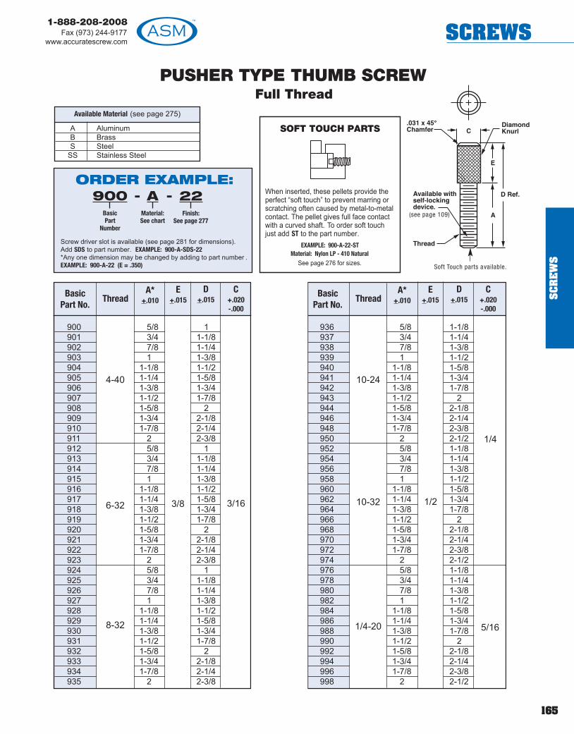
PUSHER TYPE THUMB SCREWFull Thread
SOFT TOUCH PARTS
When inserted, these pellets provide theperfect “soft touch” to prevent marring orscratching often caused by metal-to-metalcontact. The pellet gives full face contactwith a curved shaft. To order soft touchjust add ST to the part number.
EXAMPLE: 900-A-22-ST Material: Nylon LP - 410 Natural
See page 276 for sizes.
900 5/8 1901 3/4 1-1/8902 7/8 1-1/4903 1 1-3/8904 1-1/8 1-1/2905 1-1/4 1-5/8906 1-3/8 1-3/4907 1-1/2 1-7/8908 1-5/8 2909 1-3/4 2-1/8910 1-7/8 2-1/4911 2 2-3/8912 5/8 1913 3/4 1-1/8914 7/8 1-1/4915 1 1-3/8916 1-1/8 1-1/2917 1-1/4 1-5/8918 1-3/8 1-3/4919 1-1/2 1-7/8920 1-5/8 2921 1-3/4 2-1/8922 1-7/8 2-1/4923 2 2-3/8924 5/8 1925 3/4 1-1/8926 7/8 1-1/4927 1 1-3/8928 1-1/8 1-1/2929 1-1/4 1-5/8930 1-3/8 1-3/4931 1-1/2 1-7/8932 1-5/8 2933 1-3/4 2-1/8934 1-7/8 2-1/4935 2 2-3/8
936 5/8 1-1/8937 3/4 1-1/4938 7/8 1-3/8939 1 1-1/2940 1-1/8 1-5/8941 1-1/4 1-3/4942 1-3/8 1-7/8943 1-1/2 2944 1-5/8 2-1/8946 1-3/4 2-1/4948 1-7/8 2-3/8950 2 2-1/2952 5/8 1-1/8954 3/4 1-1/4956 7/8 1-3/8958 1 1-1/2960 1-1/8 1-5/8962 1-1/4 1-3/4964 1-3/8 1-7/8966 1-1/2 2968 1-5/8 2-1/8970 1-3/4 2-1/4972 1-7/8 2-3/8974 2 2-1/2976 5/8 1-1/8978 3/4 1-1/4980 7/8 1-3/8982 1 1-1/2984 1-1/8 1-5/8986 1-1/4 1-3/4988 1-3/8 1-7/8990 1-1/2 2992 1-5/8 2-1/8994 1-3/4 2-1/4996 1-7/8 2-3/8998 2 2-1/2
ThreadA*
+.010E
+.015Basic
Part No.
C+.020-.000
D+.015 Thread
A*+.010
E+.015
BasicPart No.
C+.020-.000
D+.015
4-40
6-32
8-32
3/8 3/16
10-24
10-32
1/4-20
1/2
5/16
1/4
(see page 109)
A AluminumB BrassS Steel
SS Stainless Steel
Available Material (see page 275)
Soft Touch parts available.
ORDER EXAMPLE:- -900
BasicPart
Number
AMaterial:See chart
22Finish:
See page 277
Screw driver slot is available (see page 281 for dimensions).Add SDS to part number. EXAMPLE: 900-A-SDS-22*Any one dimension may be changed by adding to part number .EXAMPLE: 900-A-22 (E = .350)
165
1-888-208-2008Fax (973) 244-9177
www.accuratescrew.com SCREWS
SC
RE
WS

166
1-888-208-2008Fax (973) 244-9177www.accuratescrew.comSCREWS
C900 5/8 1 5/16C901 3/4 1-1/8 3/8C902 7/8 1-1/4 7/16C903 1 1-3/8 1/2C904 1-1/8 1-1/2 9/16C905 1-1/4 1-5/8 5/8C906 1-3/8 1-3/4 11/16C907 1-1/2 1-7/8 3/4C908 1-5/8 2 13/16C909 1-3/4 2-1/8 7/8C910 1-7/8 2-1/4 15/16C911 2 2-3/8 1C912 5/8 1 5/16C913 3/4 1-1/8 3/8C914 7/8 1-1/4 7/16C915 1 1-3/8 1/2C916 1-1/8 1-1/2 9/16C917 1-1/4 1-5/8 5/8C918 1-3/8 1-3/4 11/16C919 1-1/2 1-7/8 3/4C920 1-5/8 2 13/16C921 1-3/4 2-1/8 7/8C922 1-7/8 2-1/4 15/16C923 2 2-3/8 1C924 5/8 1 5/16C925 3/4 1-1/8 3/8C926 7/8 1-1/4 7/16C927 1 1-3/8 1/2C928 1-1/8 1-1/2 9/16C929 1-1/4 1-5/8 5/8C930 1-3/8 1-3/4 11/16C931 1-1/2 1-7/8 3/4C932 1-5/8 2 13/16C933 1-3/4 2-1/8 7/8C934 1-7/8 2-1/4 15/16C935 2 2-3/8 1
C936 5/8 1-1/8 5/16C937 3/4 1-1/4 3/8C938 7/8 1-3/8 7/16C939 1 1-1/2 1/2C940 1-1/8 1-5/8 9/16C941 1-1/4 1-3/4 5/8C942 1-3/8 1-7/8 11/16C943 1-1/2 2 3/4C944 1-5/8 2-1/8 13/16C946 1-3/4 2-1/4 7/8C948 1-7/8 2-3/8 15/16C950 2 2-1/2 1C952 5/8 1-1/8 5/16C954 3/4 1-1/4 3/8C956 7/8 1-3/8 7/16C958 1 1-1/2 1/2C960 1-1/8 1-5/8 9/16C962 1-1/4 1-3/4 5/8C964 1-3/8 1-7/8 11/16C966 1-1/2 2 3/4C968 1-5/8 2-1/8 13/16C970 1-3/4 2-1/4 7/8C972 1-7/8 2-3/8 15/16C974 2 2-1/2 1C976 5/8 1-1/8 5/16C978 3/4 1-1/4 3/8C980 7/8 1-3/8 7/16C982 1 1-1/2 1/2C984 1-1/8 1-5/8 9/16C986 1-1/4 1-3/4 5/8C988 1-3/8 1-7/8 11/16C990 1-1/2 2 3/4C992 1-5/8 2-1/8 13/16C994 1-3/4 2-1/4 7/8C996 1-7/8 2-3/8 15/16C998 2 2-1/2 1
PUSHER TYPE THUMB SCREWCaptive Thread
.078
.095
.120
.130
.175
4-40
6-32
8-32
3/8 3/16
10-24
10-32
1/4-20
1/2
5/16
1/4
A AluminumB BrassS Steel
SS Stainless Steel
Available Material (see page 275)
Soft Touch parts available.
(see page 109)
SOFT TOUCH PARTS
When inserted, these pellets provide theperfect “soft touch” to prevent marring orscratching often caused by metal-to-metalcontact. The pellet gives full face contactwith a curved shaft. To order soft touchjust add ST to the part number.
EXAMPLE: C900-A-22-ST Material: Nylon LP - 410 Natural
See page 275 for sizes.
ORDER EXAMPLE:- -C900
BasicPart
Number
AMaterial:See chart
22Finish:
See page 277
Screw driver slot is available (see page 281 for dimensions).Add SDS to part number. EXAMPLE: C900-A-SDS-22*Any one dimension may be changed by adding to part number .EXAMPLE: C900-A-22 (K = 1/4)
BasicPartNo.
Thread A+.010
E+.015
D+.015
C+.020-.000
K*+.010
G+.015
BasicPartNo.
Thread A+.010
E+.015
D+.015
C+.020-.000
K*+.010
G+.015
SC
RE
WS

167
1-888-208-2008Fax (973) 244-9177
www.accuratescrew.com SCREWS
THUMB SCREW
18000 4-40 3/8 3/16 5/8 5/1618002 4-40 3/8 3/16 11/16 3/818004 4-40 3/8 3/16 3/4 7/1618006 6-32 3/8 3/16 11/16 3/818008 6-32 3/8 3/16 3/4 7/1618010 6-32 3/8 3/16 13/16 1/218012 8-32 7/16 3/16 11/16 3/818014 8-32 7/16 3/16 13/16 1/2
18016 8-32 7/16 3/16 15/16 5/818018 10-32 7/16 3/16 11/16 3/818020 10-32 7/16 3/16 13/16 1/218022 10-32 7/16 3/16 15/16 5/818024 1/4-20 1/2 1/4 3/4 3/818026 1/4-20 1/2 1/4 7/8 1/218028 1/4-20 1/2 1/4 1 5/818030 1/4-20 1/2 1/4 1-1/8 3/4
(see page 109)
B BrassN* NylonS Steel
SS Stainless SteelD* Delrin
Available Material (see page 275)
*Knurl is less pronounced than withmetallic knurling. See page 187 forknurled nylon thumb screws.
SOFT TOUCH PARTS
When inserted, these pellets provide theperfect “soft touch” to prevent marring orscratching often caused by metal-to-metalcontact. The pellet gives full face contactwith a curved shaft. To order soft touchjust add ST to the part number.
EXAMPLE: 18000-A-1-ST Material: Nylon LP - 410 Natural
See page 276 for sizes.
ORDER EXAMPLE:- -18000
BasicPart
Number
AMaterial:See chart
1Finish:
See page277
Screw driver slot is available, add SDS to part number. (For slotdimensions see page 281.) EXAMPLE: 18000-A-SDS-1*Any one dimension may be changed, by adding to part number. EXAMPLE: 18000-A-1 (A-1/2)
BasicPartNo.
ThreadA*
+.020-.000
B*+.015
C*+.015
D*+.010
BasicPartNo.
ThreadA*
+.020-.000
B*+.015
C*+.015
D*+.010
SC
RE
WS
! TECH TIPSome finishes will change the major and pitchdiameter of the class 2A exter nal threads. Ifrequired, allowances can be made to ensur e theparts maintain the correct major and pitch diameter.

168
1-888-208-2008Fax (973) 244-9177www.accuratescrew.comSCREWS
SC
RE
WS
PUSHER TYPE THUMB SCREWSee page 187 for molded thumb screws.
C18040C18042C18044C18046C18048C18050C18052C18054C18056C18058C18060C18062C18064C18066C18068C18070C18072C18074C18076C18078C18080C18082C18084C18090
1/2 5/16 5/329/16 3/8 3/165/8 7/16 7/32
11/16 1/2 1/41/2 5/16 5/329/16 3/8 3/165/8 7/16 7/32
11/16 1/2 1/49/16 3/8 3/165/8 7/16 7/32
11/16 1/2 1/43/4 9/16 9/32
13/16 5/8 5/169/16 3/8 3/165/8 7/16 7/32
11/16 1/2 1/43/4 9/16 9/32
13/16 5/8 5/163/4 1/2 1/4
13/16 9/16 9/327/8 5/8 5/16
15/16 11/16 11/321 3/4 3/8
2-3/4 2-1/2 1-1/4
4-40
5/16
3/16
6-32
8-32
10-32
1/4-20
3/8
7/16
1/2 1/4
.095
.120
.130
.175
Basic PartNumber
Thread A+.020
B+.015
C+.015
D+.015
K+.010
G+.005
Full Thread
(see page 109)
.078
180401804218044180461804818050180521805418056180581806018062180641806618068180701807218074180761807818080180821808418090
1/2 5/169/16 3/85/8 7/16
11/16 1/21/2 5/169/16 3/85/8 7/16
11/16 1/29/16 3/85/8 7/16
11/16 1/23/4 9/16
13/16 5/89/16 3/85/8 7/16
11/16 1/23/4 9/16
13/16 5/83/4 1/2
13/16 9/167/8 5/8
15/16 11/161 3/4
2-3/4 2-1/2
4-40
5/16
3/16
6-32
8-32
10-32
1/4-20
3/8
7/16
1/2 1/4
BasicPart
NumberThread A
+.020B
+.015C
+.015D
+.015
SOFT TOUCHPARTS
When inserted, thesepellets provide the perfect“soft touch” to preventmarring or scratching oftencaused by metal-to-metalcontact. The pellet givesfull face contact with acurved shaft. To order softtouch just add ST to thepart number.
EXAMPLE: 18040-A-22-ST Material: Nylon LP - 410 Natural
See page 276 for sizes.ORDER EXAMPLE:- -18040
BasicPart
Number
AMaterial:See chart
22Finish:
See page277
Screw Driver Slot Option - add SDS to part numberEXAMPLE: 18040-A-SDS-22Change any dimension, add changes to end of part number . EXAMPLE: 18040-A -22 (A=1/2)
Captive Thread
(see page 109)
ORDER EXAMPLE:- -C18040
BasicPart
Number
AMaterial:See chart
22Finish:
See page277
Change any dimension, add changes to end of part number .EXAMPLE: C18040-A-22 (K=1/8)
**Knurl is less pronounced than metallic knurling.
A AluminumB BrassN** NylonS Steel SS Stainless SteelD** Delrin
Available Material (see page 275)
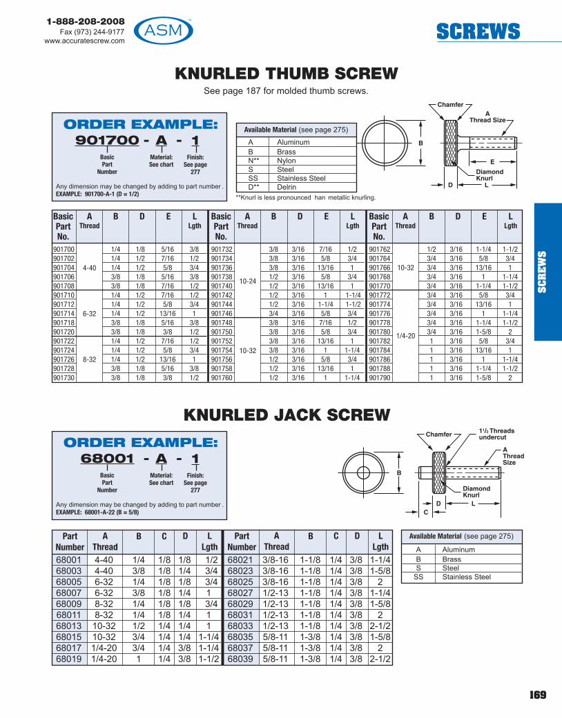
169
1-888-208-2008Fax (973) 244-9177
www.accuratescrew.com SCREWS
SC
RE
WS
**Knurl is less pronounced han metallic knurling.
KNURLED THUMB SCREWSee page 187 for molded thumb screws.
901700 1/4 1/8 5/16 3/8901702 1/4 1/2 7/16 1/2901704 1/4 1/2 5/8 3/4901706 3/8 1/8 5/16 3/8901708 3/8 1/8 7/16 1/2901710 1/4 1/2 7/16 1/2901712 1/4 1/2 5/8 3/4901714 1/4 1/2 13/16 1901718 3/8 1/8 5/16 3/8901720 3/8 1/8 3/8 1/2901722 1/4 1/2 7/16 1/2901724 1/4 1/2 5/8 3/4901726 1/4 1/2 13/16 1901728 3/8 1/8 5/16 3/8901730 3/8 1/8 3/8 1/2
901732 3/8 3/16 7/16 1/2901734 3/8 3/16 5/8 3/4901736 3/8 3/16 13/16 1901738 1/2 3/16 5/8 3/4901740 1/2 3/16 13/16 1901742 1/2 3/16 1 1-1/4901744 1/2 3/16 1-1/4 1-1/2901746 3/4 3/16 5/8 3/4901748 3/8 3/16 7/16 1/2901750 3/8 3/16 5/8 3/4901752 3/8 3/16 13/16 1901754 3/8 3/16 1 1-1/4901756 1/2 3/16 5/8 3/4901758 1/2 3/16 13/16 1901760 1/2 3/16 1 1-1/4
901762 1/2 3/16 1-1/4 1-1/2901764 3/4 3/16 5/8 3/4901766 3/4 3/16 13/16 1901768 3/4 3/16 1 1-1/4901770 3/4 3/16 1-1/4 1-1/2901772 3/4 3/16 5/8 3/4901774 3/4 3/16 13/16 1901776 3/4 3/16 1 1-1/4901778 3/4 3/16 1-1/4 1-1/2901780 3/4 3/16 1-5/8 2901782 1 3/16 5/8 3/4901784 1 3/16 13/16 1901786 1 3/16 1 1-1/4901788 1 3/16 1-1/4 1-1/2901790 1 3/16 1-5/8 2
4-40
6-32
8-32
10-24
10-32
10-32
1/4-20
68001 4-40 1/4 1/8 1/8 1/268003 4-40 3/8 1/8 1/4 3/468005 6-32 1/4 1/8 1/8 3/468007 6-32 3/8 1/8 1/4 168009 8-32 1/4 1/8 1/8 3/468011 8-32 1/4 1/8 1/4 168013 10-32 1/2 1/4 1/4 168015 10-32 3/4 1/4 1/4 1-1/468017 1/4-20 3/4 1/4 3/8 1-1/468019 1/4-20 1 1/4 3/8 1-1/2
68021 3/8-16 1-1/8 1/4 3/8 1-1/468023 3/8-16 1-1/8 1/4 3/8 1-5/868025 3/8-16 1-1/8 1/4 3/8 268027 1/2-13 1-1/8 1/4 3/8 1-1/468029 1/2-13 1-1/8 1/4 3/8 1-5/868031 1/2-13 1-1/8 1/4 3/8 268033 1/2-13 1-1/8 1/4 3/8 2-1/268035 5/8-11 1-3/8 1/4 3/8 1-5/868037 5/8-11 1-3/8 1/4 3/8 268039 5/8-11 1-3/8 1/4 3/8 2-1/2
AThread
B CPartNumber
D LLgth
AThread
B CPartNumber
D LLgth
KNURLED JACK SCREW
A AluminumB BrassN** NylonS Steel SS Stainless SteelD** Delrin
Available Material (see page 275)
A AluminumB BrassS Steel
SS Stainless Steel
Available Material (see page 275)
ORDER EXAMPLE:- -901700
BasicPart
Number
AMaterial:See chart
1Finish:
See page277
Any dimension may be changed by adding to part number .EXAMPLE: 901700-A-1 (D = 1/2)
ORDER EXAMPLE:- -68001
BasicPart
Number
AMaterial:See chart
1Finish:
See page277
Any dimension may be changed by adding to part number .EXAMPLE: 68001-A-22 (B = 5/8)
BasicPartNo.
AThread
B D E LLgth
BasicPartNo.
AThread
B D E LLgth
BasicPartNo.
AThread
B D E LLgth

170
1-888-208-2008Fax (973) 244-9177www.accuratescrew.comSCREWS
THUMB SCREWShoulder Type
900005* 6-32 1/2900009* 6-32 3/4900011 6-32 1900015* 8-32 1/2900019* 8-32 3/4900021 8-32 1900025* 10-24 1/2900029* 10-24 3/4900031* 10-24 1900030* 10-32 3/4900032* 10-32 1900034 10-32 1-1/2900036 10-32 2900041* 1/4-20 3/4900043* 1/4-20 1900047* 1-4/20 1-1/2900049* 1/4-20 2900053* 5/16-18 1/2900055* 5/16-18 3/4900057* 5/16-18 1900059 5/16-18 1-1/4900061* 5/16-18 1-1/2900063 5/16-18 2900065 5/16-18 2-1/2900067 5/16-18 3900069* 3/8-16 3/4900071* 3/8-16 1900073 3/8-16 1-1/4900075* 3/8-16 1-1/2900077* 3/8-16 2900079 3/8-16 2-1/2900081 3/8-16 3
BasicPart Number
ThreadL
Length
Approximate dimensions are for reference only.
FLAT POINT~ • ~
FLATF
Material
*Shoulder Type Only. Shoulder Type Thumb Screws with Standard CoarseThreaded and Flat Point in Steel are carried in stock. All others are approximately14-16 weeks delivery and 5,000 minimum order .
ORDER EXAMPLE:900005
BasicPart
Number
SMaterial:
Steel
FFlat
Point
-- 7Finish*:
See page277
-
*The Cadmium Plate Finish (7) is recommended for Steel.
SC
RE
WS
CHead Width
DHead Height
EShoulder Dia.
6-32 0.31 0.29 0.33 0.31 0.25 0.238-32 0.36 0.34 0.38 0.36 0.31 0.2910-32 0.42 0.40 0.48 0.46 0.35 0.321/4-20 0.55 0.52 0.64 0.61 0.47 0.445/16-18 0.70 0.67 0.78 0.75 0.59 0.563/8-16 0.83 0.80 0.95 0.92 0.76 0.71
Max. Min. Max. Min. Max. Min.
ThreadSize
! TECH TIPDon’t have a 3D CAD softwae package or viewer?Not a problem! You can view our parts fromwww.accuratescrew.com in 3D right in your webbrowser (Internet Explorer only)!

171
1-888-208-2008Fax (973) 244-9177
www.accuratescrew.com SCREWS
CAPTIVE THUMB SCREW WITH KNOBSKnobs Are Pressed On Securely - They Won’t Come off
114114 4-40 .250-.625 5/32 .078114116 6-32 .375-1.250 3/16 .095114118 8-32 .375-1.250 3/16 .120114120 10-32 .375-1.500 1/4 .130114121 1/4-20 .375-3.000 1/4 .175114111 1/4-28 .375-3.000 1/4 .175114113 5/16-18 .500-3.500 3/8 .230114115 3/8-16 .500-5.000 3/8 .280
ScrewPart No. Thread Increments of 1/16 B
+.005K
+.010
S Heat Treated Alloy SteelSS Stainless Steel 18-8
Material For Captive Thumb Screws Specifications
(see page 275)
Knob(see below)
ScrewSize A B C
Knob Specs
Black BLRed RGray G
Select KNOB From Charts Below
Select SCREW From Charts Below
#4 5/16 11/64 9/32#6 3/8 3/16 21/64#8 1/2 7/32 3/8#10 5/8 1/4 27/641/4 3/4 5/16 1/25/16 1 13/32 19/32
ORDER EXAMPLE:114116
BasicPart
Number
.500Length:
See chart
SSMaterial:See chart
KKnob Code:Knurled (K),Rosette (R)or Tee (T)
-- 12Finish:
See page277
- BLKnob Color:See chart
- -
Select knob and screw from charts.
Screw(see below)
Assembled
Material: Dupont Delrin
Colors Available Code
Knurled KnobCode Letter (K)
Rosette KnobCode Letter (R)
Tee KnobCode Letter (T)
ScrewSize A B C
Knob Specs
Black BLGray GBeige B
1/4 1-1/2 3/8 1/25/16 1-1/2 13/32 37/643/8 1-1/2 15/32 45/64
Material: Dupont Delrin
Colors Available Code
ScrewSize A B C
Knob Specs
Black BLRed RGray GBeige B
#10 1 1/4 7/161/4 1-1/4 5/16 33/645/16 1-1/2 13/32 5/83/8 1-3/4 15/32 23/32
Material: Dupont Delrin
Colors Available Code
SC
RE
WS

172
1-888-208-2008Fax (973) 244-9177www.accuratescrew.comSCREWS
SC
RE
WS
SOCKET HEAD CAP SCREWSelf-Sealing/Self-Locking Devices available, see page 109.
Available Material (see page 275)
Stainless Steel 18-8
* Tolerances, see page 281
1/8 630003/16 630025/16 630041/4 630061/2 630083/8 630105/8 630123/4 630141 63016
1/8 630183/16 630201/4 630223/8 630241/2 630265/8 630283/4 630301 63032
1/8 630343/16 630367/32 630381/4 630405/16 630423/8 630447/16 630461/2 630485/8 630503/4 630527/8 630541 63056
1/8 630583/16 630601/4 630625/16 630643/8 630665/8 630681/2 630703/4 63072
7/8 630741 63076
1/8 630783/16 630801/4 630825/16 630843/8 630867/16 630881/2 630909/16 630925/8 630943/4 630987/8 630961 63100
1-1/4 631021-3/8 631041-1/2 631061-3/4 63108
2 631101/8 631123/16 631141/4 631165/16 631183/8 631207/16 631221/2 631245/8 631263/4 631307/8 631281 63132
1-1/4 631341-1/2 63136
2 631381/8 631403/16 631421/4 631443/8 63146
7/16 631481/2 631509/16 631525/8 631543/4 631567/8 631581 63160
1-1/8 631621-1/4 631641-3/8 631661-1/2 631681-3/4 63170
2 631722-1/4 631742-1/2 631762-3/4 63178
3 631803/16 631821/4 631845/16 631863/8 631887/16 631901/2 631925/8 631943/4 631987/8 631967/8 632001 63202
1-1/4 632041-1/2 632061/8 632083/16 632101/4 632125/16 632143/8 632167/16 632181/2 63220
9/16 632225/8 632243/4 632267/8 632281 63230
1-1/8 632321-1/4 632341-3/8 632361-1/2 632381-3/4 63240
2 632422-1/4 632442-1/2 63246
3 632483-1/4 63250
4 632511/4 632523/8 632541/2 632565/8 632583/4 632607/8 632621 63264
1-1/4 632661-1/2 63268
2 632701/4 632725/16 632743/8 632767/16 632781/2 632809/16 632825/8 63284
11/16 632863/4 632887/8 632901 63292
1-1/8 632941-1/4 632961-3/8 632981-1/2 633001-5/8 633021-3/4 63304
2 633062-1/4 633082-1/2 633102-3/4 63312
3 633143-1/2 63316
4 633181/4 633205/16 633223/8 633247/16 633261/2 633289/16 633305/8 63332
11/16 633343/4 633367/8 633381 63340
1-1/8 633421-1/4 633441-3/8 633461-1/2 633481-5/8 633501-3/4 63352
2 633542-1/4 633562-1/2 633582-3/4 63360
3 633623-1/4 633643-1/2 63366
4 63368
NOTE: Standard socket products have a class 3A hreads, however, once plated, threads will not enter 3A GO, NO GO Cages.Minimum thread length is 2-1/2 times diameter .
For Tolerances, head dimensions, and other specifications, see pages 281-287.
THREAD: Fully formed threads - Unified National Coarse and Fine. Available in 4-40 and up only.
ORDER EXAMPLE:- -63004
BasicPart
Number
SSStainless
Steel18-8
12Finish:
See page277
To order Low Profile Head, add LP to part number (available in 4-40 thread and up only).EXAMPLE: 63004-SS-LP -7
Diameter
Threadsper Inch
Key Size
LengthUnderHead*
BasicPart
Number
Diameter
Threadsper Inch
Key Size
LengthUnderHead*
BasicPart
Number
Diameter
Threadsper Inch
LengthUnderHead*
BasicPart
Number
Diameter
Threadsper Inch
LengthUnderHead*
BasicPart
Number
Diameter
Threadsper Inch
LengthUnderHead*
BasicPart
Number
#0
.80 UNF
.050 Key
#1
72 UNF
1/16 Key
#2
56 UNC
5/64 Key
#3
48 UNC
5/64 Key
#3 48 UNC5/64 Key
#4
40 UNC
3/32 Key
#5
.40 UNC
3/32 Key
#6
32 UNC
#6
32 UNC
#6
40 UNF
#8
32 UNC
#8
32 UNC
#8
36 UNF
#10
24 UNC
#10
24 UNC
#10
32 UNF

173
1-888-208-2008Fax (973) 244-9177
www.accuratescrew.com SCREWS
SC
RE
WS
1/4 633705/16 633723/8 633747/16 633761/2 633789/16 633805/8 633823/4 633847/8 633861 63388
1-1/8 633901-1/4 633921-3/8 633941-1/2 633961-5/8 633981-3/4 634001-7/8 63402
2 634042-1/4 634062-3/8 634082-1/2 634102-3/4 63412
3 634143-1/4 634163-1/2 634183-3/4 63420
4 634224-1/2 63424
5 634265-1/2 63428
6 634308 63432
1/4 634347/16 634363/8 634381/2 634409/16 634425/8 634443/4 634467/8 634481 63450
1-1/8 634521-1/4 634541-3/8 634561-1/2 634581-3/4 63460
2 634622-1/4 634642-1/2 63466
2-3/4 634683 63470
3-1/4 634723-1/2 63474
4 634764-1/2 63478
5 634805-1/2 63482
6 634841/4 634865/16 634883/8 634901/2 634925/8 634943/4 634967/8 634981 63500
1-1/8 635021-1/4 635041-3/8 635061-7/16 635081-1/2 635101-5/8 635121-3/4 63514
2 635162-1/8 635182-1/4 635202-1/2 635222-3/4 63524
3 635263-1/4 635283-1/2 635303-3/4 63532
4 635344-1/2 63536
5 635385-1/2 63540
6 635428 63544
3/8 635461/2 635485/8 635503/4 635527/8 635541 63556
1-1/4 635581-1/2 635601-5/8 635621-3/4 63564
2 635662-1/4 635682-1/2 635702-3/4 63572
3 635743-1/4 635763-1/2 635783-3/4 63580
4 635824-1/2 63584
5 635865-1/2 63588
6 635903/8 635921/2 635945/8 635963/4 635987/8 636001 63602
1-1/8 636041-1/4 636061-3/8 636081-1/2 636101-5/8 636121-3/4 636141-7/8 63616
2 636182-1/4 636202-1/2 636222-3/4 63624
3 636263-1/4 636283-1/2 636303-3/4 63632
4 636344-1/4 636384-1/2 636404-3/4 63642
5 636445-1/2 63646
6 636486-1/2 63650
7 636528 63654
3/8 636561/2 636585/8 636603/4 636627/8 63664
1 636661-1/8 636681-1/4 636701-1/2 636721-3/4 63674
2 636762-1/4 636782-1/2 636802-3/4 63682
3 636843-1/4 636863-1/2 63688
4 636904-1/2 63692
5 636945-1/2 63696
6 636981/2 637005/8 637023/4 637047/8 637061 63708
1-1/4 637101-3/8 637121-1/2 637141-3/4 637161-7/8 63718
2 637202-1/4 637222-1/2 637242-3/4 63726
3 637283-1/4 637303-1/2 63732
4 637344-1/2 63736
5 637385-1/2 63740
6 637421/2 637445/8 637463/4 637487/8 637501 63752
1-1/4 637541-1/2 637561-3/4 63758
2 637602-1/4 63762
2-1/2 637642-3/4 63766
3 637683-1/4 637703-1/2 63772
4 637746 63776
3/8 637781/2 637805/8 637823/4 637847/8 637861 63788
11/8 637901-1/4 637921-3/8 637941-1/2 637961-5/8 637981-3/4 638001-7/8 63802
2 638042-1/4 638062-3/8 638082-1/2 638102-3/4 63812
3 638143-1/4 638163-1/2 638183-3/4 63820
4 638224-1/4 638244-1/2 638264-3/4 63828
5 638305-1/4 638325-1/2 63834
6 638367 63838
7-1/2 638408 63842
8-1/2 638449 63846
9-1/2 6384810 6385011 6385212 63854
*Tolerances,see page 281
NOTE: Standard socket products have a class 3A threads, however, once plated, threads will not enter 3A GO, NO GO Cages.Minimum thread length is 2-1/2 times diameter .
Diameter
Threadsper Inch
LengthUnderHead*
BasicPart
Number
Diameter
Threadsper Inch
LengthUnderHead*
BasicPart
Number
Diameter
Threadsper Inch
LengthUnderHead*
BasicPart
Number
Diameter
Threadsper Inch
LengthUnderHead*
BasicPart
Number
Diameter
Threadsper Inch
LengthUnderHead*
BasicPart
Number
1/4
20 UNC
1/4
28 UNF
1/4
28 UNF
5/16
18 UNC
5/16
24 UNF
5/16
24 UNF
3/8
16 UNC
3/8
24 UNF
3/8
24 UNF
7/16
14 UNC
7/16
20 UNF
7/16
20 UNF
1/2
13 UNC
SOCKET HEAD CAP SCREWSelf-Sealing/Self-Locking Devices available, see page 109.
Available Material(see page 275)
For Tolerances, head dimensions, and otherspecifications, see pages 281-287.THREAD: Fully formed threads - Unified Na tionalCoarse and Fine.Minimum thread length 2.5 x diameter. Available in4-40 and up only.
Stainless Steel 18-8,302 Series
ORDER EXAMPLE:- -63438
BasicPart
Number
SSStainless
Steel18-8
12Finish:
See page277
To order Low Profile Head, add LP to part number.EXAMPLE: 63438-SS-LP -7

174
1-888-208-2008Fax (973) 244-9177www.accuratescrew.comSCREWS
SC
RE
WS
1/16 991003/32 991021/8 991043/16 991061/4 991071/16 991083/32 991101/8 991123/16 991141/4 991161/16 991183/32 991201/8 991223/16 991241/4 991263/32 991281/8 991303/16 991321/4 991361/8 991383/16 991401/4 991425/16 991443/8 991461/2 991485/8 991501/8 991523/16 991541/4 991565/16 991583/8 991601/2 991625/8 991641/8 991663/16 99168
1/4 991705/16 991723/8 991741/2 991765/8 991783/4 991801/8 991823/16 991841/4 991865/16 991883/8 991901/2 991925/8 991943/4 991961/8 991983/16 992001/4 992045/16 992063/8 992081/8 992103/16 992121/4 992145/16 992163/8 992181/8 992203/16 992221/4 992245/16 992263/8 992287/16 992301/2 992325/8 992343/4 992367/8 992381 99240
1/8 992423/16 992441/4 992465/16 992483/8 992507/16 992521/2 992545/8 992563/4 992587/8 992601 99262
3/16 992641/4 992665/16 992683/8 992707/16 992721/2 992745/8 992763/4 992787/8 992801 99282
1-1/4 992843/16 992861/4 992885/16 992903/8 992927/16 992941/2 992965/8 992983/4 993007/8 993021 99304
1-1/4 993063/16 993081/4 99310
5/16 993123/8 993147/16 993161/2 993185/8 993203/4 993227/8 993241 99326
1-1/4 993281-1/2 993301-3/4 99332
2 993343/16 993361/4 993385/16 993403/8 993427/16 993441/2 993465/8 993483/4 993507/8 993521 99354
1-1/4 993561-1/2 993581-3/4 99360
2 993621/4 993645/16 993663/8 993677/16 993681/2 993705/8 993723/4 993747/8 993761 99378
1-1/4 993801-1/2 993821-3/4 99384
2 993861/4 993885/16 993903/8 993917/16 993921/2 993945/8 993963/4 993987/8 994001 99402
1-1/4 994041-1/2 994061-3/4 99408
2 994101/4 994125/16 994143/8 994167/16 994181/2 994205/8 994223/4 994247/8 994261 99428
1-1/4 994301-1/2 994321-3/4 99434
2 994362-1/2 994381/4 994405/16 994423/8 99444
7/16 99446
SOCKET SET SCREWCup Point
Available Material (see page 275)
Thread
SS Stainless Steel 18-8, 302 Series
Fully Formed ThreadsUnified National Coarse and Fine 3A
ORDER EXAMPLE:- -99100
BasicPart
Number
SSStainless
Steel18-8
12Finish:
See page277
Diameter
Threadsper Inch
Key Size
OverallLength
BasicPart
Number
Diameter
Threadsper Inch
Key Size
OverallLength
BasicPart
Number
Diameter
Threadsper Inch
Key Size
OverallLength
BasicPart
Number
Diameter
Threadsper Inch
Key Size
OverallLength
BasicPart
Number
Diameter
Threadsper Inch
Key Size
OverallLength
BasicPart
Number
#080 UNF
.028 Key
#172 UNF
.035 Key
#256 UNC.035 Key
#348 UNC.050 Key
#440 UNC.050 Key
#448 UNF
.050 Key
#540 UNC
1/16 Key
#540 UNC
1/16 Key
#544 UNF
1/16 Key
#632 UNC
1/16 Key
#640 UNF
1/16 Key
#832 UNC
5/64 Key
#836 UNF
5/64 Key
#1024 UNC
3/32 Key
#1032 UNF
3/32 Key
1/420 UNC1/8 Key
1/420 UNC1/8 Key
1/428 UNF1/8 Key
5/1618 UNC
5/32 Key
5/1618 UNC
5/32 Key
5/1624 UNF
5/32 Key
3/816 UNC
3/16 Key
3/824 UNF
3/16 Key

175
1-888-208-2008Fax (973) 244-9177
www.accuratescrew.com SCREWS
SC
RE
WS
1/2 994485/8 994503/4 994527/8 994541 99456
1-1/4 994581-1/2 994601-3/4 99462
2 994642-1/2 994663/8 994687/16 994701/2 994725/8 994743/4 994767/8 994781 99480
1-1/4 994821-1/2 99484
2 99486
3/8 994887/16 994901/2 994925/8 994943/4 994967/8 994981 99500
1-1/4 995021-1/2 99504
2 995063/8 995087/16 995101/2 995125/8 995143/4 995167/8 995181 99520
1-1/4 995221-1/2 995241-3/4 99526
2 995282-1/2 99530
3 995323/8 995347/16 995361/2 995385/8 995403/4 995427/8 995441 99546
1-1/4 995481-1/2 995501-3/4 99552
2 995542-1/2 99556
3 995581/2 995605/8 995623/4 995647/8 99566
1 995681-1/4 995701-1/2 995721-3/4 99574
2 995762-1/2 99578
3 995801/2 995825/8 995843/4 995867/8 995881 99590
1-1/4 995921-1/2 995941-3/4 99596
2 995982-1/2 99600
3 996025/8 996043/4 99606
1 996081-1/4 996101-1/2 996121-3/4 99614
2 996162-1/2 99618
3 996207/8 996221 99624
1-1/2 996262 99628
2-1/2 996303 996321 99634
1-1/2 996362 99638
2-1/2 996403 99642
SOCKET SET SCREWCup Point
Available Material (see page 275)
Thread
SS Stainless Steel 18-8, 302 Series
Fully Formed ThreadsUnified National Coarse and Fine 3A
ORDER EXAMPLE:- -99448
BasicPart
Number
SSStainless
Steel18-8
12Finish:
See page277
Diameter
Threadsper Inch
Key Size
OverallLength
BasicPart
Number
Diameter
Threadsper Inch
Key Size
OverallLength
BasicPart
Number
Diameter
Threadsper Inch
Key Size
OverallLength
BasicPart
Number
Diameter
Threadsper Inch
Key Size
OverallLength
BasicPart
Number
Diameter
Threadsper Inch
Key Size
OverallLength
BasicPart
Number
3/824 UNF
3/16 Key
7/1614 UNC7/32 Key
7/1620 UNF
7/32 Key
1/213 UNC1/4 Key
1/213 UNC
1/220 UNF1/4 Key
5/811 UNC5/16 Key
5/811 UNC5/16 Key
5/818 UNF
5/16 Key
3/410 UNC3/8 KEY
3/410 UNC3/8 Key
7/89 UNC
1/2 Key
18 UNC
9/16 Key

176
1-888-208-2008Fax (973) 244-9177www.accuratescrew.comSCREWS
SC
RE
WS
NYLON TIP HEX SOCKET SET SCREW
Thread D L Part Number T
1/32 1/32 1/8 111324 SS2-56 1/32 1/32 1/4 111326 SS1/16 1/32 1/8 111328 SS
4-40 1/16 1/32 1/4 111330 SS1/16 1/32 3/8 111332 SS1/16 1/32 1/8 111334 SS
6-32 1/16 1/32 1/4 111336 SS1/16 1/32 3/8 111338 SS7/64 3/64 1/8 111340 SS7/64 3/64 3/16 111342 SS
8-32 7/64 3/64 1/4 111344 SS7/64 3/64 3/8 111346 SS7/64 3/64 1/2 111348 SS1/8 3/64 3/16 111350 SS1/8 3/64 1/4 111352 SS
10-24 1/8 3/64 3/8 111354 SS1/8 3/64 1/2 111356 SS1/8 3/64 5/8 111358 SS1/8 3/64 3/16 111360 SS1/8 3/64 1/4 111362 SS
10-32 1/8 3/64 3/8 111364 SS1/8 3/64 1/2 111366 SS1/8 3/64 5/8 111368 SS1/8 1/16 1/4 111370 SS1/8 1/16 5/16 111372 SS1/8 1/16 3/8 111374 SS1/4-20 1/8 1/16 1/2 111376 SS1/8 1/16 5/8 111378 SS1/8 1/16 3/4 111380 SS1/8 1/16 1/4 111382 SS1/4-28 1/8 1/16 5/16 111384 SS
Thread or ScrewLocking
18-8 Stainless Steel18-8 Stainless Steel18-8 Stainless Steel18-8 Stainless Steel18-8 Stainless Steel18-8 Stainless Steel18-8 Stainless Steel18-8 Stainless Steel18-8 Stainless Steel18-8 Stainless Steel18-8 Stainless Steel18-8 Stainless Steel18-8 Stainless Steel18-8 Stainless Steel18-8 Stainless Steel18-8 Stainless Steel18-8 Stainless Steel18-8 Stainless Steel18-8 Stainless Steel18-8 Stainless Steel18-8 Stainless Steel18-8 Stainless Steel18-8 Stainless Steel18-8 Stainless Steel18-8 Stainless Steel18-8 Stainless Steel18-8 Stainless Steel18-8 Stainless Steel18-8 Stainless Steel18-8 Stainless Steel18-8 Stainless Steel
Material
Available Material (see page 275)
SS Stainless Steel 18-8, 302 Series
ORDER EXAMPLE:- -111324
BasicPart
Number
SSStainless
Steel18-8
11Finish:
See page277

177
1-888-208-2008Fax (973) 244-9177
www.accuratescrew.com SCREWS
SC
RE
WS
SLOTTED ROUND HEAD MACHINE SCREWSelf-sealing devices, see page 119. Self-locking devices, see page 109.
Thread Size D H W C
2 .135-.165 .045-.075 .013-.043 .030-.0603 .169-.187 .067-.078 .027-.035 .040-.0534 .193-.225 .055-.086 .020-.050 .035-.0656 .240-.275 .085-.115 .030-.060 .045-.0758 .275-.309 .095-.125 .035-.065 .050-.08010 .310-.359 .115-.145 .040-.070 .060-.0901/4 .443-.490 .145-.175 .055-.085 .075-.109
N Nylon, Zytel 101 UL 94V2B Brass, Composition 360S Steel, low carbon 1018 ASTM 108
SS Stainless Steel, 18-8, 302-304 series
Available Material (see page 275)
112424 1-64 3/16112426 2-56 1/8112428 2-56 5/32112430 2-56 3/16112432 2-56 1/4112434 2-56 9/32112436 2-56 5/16112438 2-56 3/8112440 2-56 7/16112442 2-56 1/2112444 2-56 9/16112446 2-56 5/8112448 2-56 3/4112450 2-56 1112452 3-48 1/8112454 3-48 3/16112456 3-48 1/4112458 3-48 3/8112460 3-48 1/2112462 3-48 9/16112464 4-40 1/8112466 4-40 9/64112468 4-40 3/16112470 4-40 1/4112472 4-40 9/32112474 4-40 5/16112476 4-40 3/8112478 4-40 7/16112480 4-40 1/2112482 4-40 9/16112484 4-40 5/8112486 4-40 11/16112488 4-40 3/4112490 4-40 7/8112492 4-40 1112494 4-40 1-1/8
112496 4-40 1-1/4112498 6-32 3/32112500 6-32 1/8112502 6-32 3/16112504 6-32 1/4112506 6-32 5/16112508 6-32 3/8112510 6-32 7/16112512 6-32 1/2112514 6-32 5/8112516 6-32 3/4112518 6-32 1112520 6-32 1-1/8112522 6-32 1-1/4112524 6-32 1-1/2112526 6-32 1-3/4112528 6-40 3/8112530 8-32 1/8112532 8-32 3/16112534 8-32 1/4112536 8-32 5/16112538 8-32 3/8112540 8-32 7/16112542 8-32 1/2112544 8-32 5/8112546 8-32 3/4112548 8-32 7/8112550 8-32 1 112552 8-32 1-1/8112554 8-32 1-1/4112556 8-32 1-3/8112558 8-32 1-1/2112560 8-32 1-3/4112562 8-32 2112564 10-24 1/8112566 10-24 3/16
112568 10-24 1/4112570 10-24 5/16112572 10-24 3/8112574 10-24 1/2112576 10-24 5/8112578 10-24 3/4112580 10-24 1112582 10-24 1-1/4112584 10-24 1-1/2112586 10-32 1/8112588 10-32 3/16112590 10-32 1/4112592 10-32 5/16112594 10-32 3/8112696 10-32 1/2112598 10-32 5/8112600 10-32 3/4112602 10-32 7/8112604 10-32 1112606 10-32 1-1/4112608 10-32 1-1/2112610 10-32 2112612 1/4-20 1/4112614 1/4-20 5/16112616 1/4-20 3/8112618 1/4-20 1/2112620 1/4-20 5/8112622 1/4-20 3/4112624 1/4-20 7/8112626 1/4-20 1112628 1/4-20 1-1/4112630 1/4-20 1-1/2112632 1/4-20 1-3/4112634 1/4-20 2
Natural 1Black 2Red 3Blue 4Purple 5Brown 6Orange 7Green 8Yellow 9
Color Code
ORDER EXAMPLE:- -112424
BasicPart
Number
SSMaterial:See chart
1Finish:
See page277
Choose color from chart, otherwise Natural is provided.For Nylon parts: Example: 112424-N-2 Black
CaptiveNylon
ScrewsSee page186 fordetails.
Basic PartNumber Thread L Basic Part
Number Thread L Basic PartNumber Thread L

178
1-888-208-2008Fax (973) 244-9177www.accuratescrew.comSCREWS
SC
RE
WS
SS Stainless SteeL 18-8, 302-304 seriesN Nylon Zytel 101 ul 94v2
Available Material (see page 275)
HEXAGON SOCKET HEAD CAP SCREWSelf-sealing devices, see page 119. Self-locking devices, see page 109.
112832 4-40112834 4-40112836 4-40112838 4-40112840 4-40112842 4-40112844 4-40112846 4-40112848 4-40112850 4-40112852 4-40112854 4-40112856 4-40112858 4-40112860 4-40112862 6-32112864 6-32112866 6-32112868 6-32112870 6-32112872 6-32112874 6-32112876 6-32112878 6-32112880 6-32112882 6-32112884 6-32112886 6-32112888 6-32112890 6-32112892 6-40112894 8-32112896 8-32112898 8-32112900 8-32112902 8-32112904 8-32112906 8-32
112908 8-32112910 8-32112912 8-32112914 8-32112916 8-32112918 8-32112920 8-32112922 8-32112924 8-32112926 10-24112928 10-24112930 10-24112932 10-24112934 10-24112936 10-24112938 10-24112940 10-24112942 10-24112944 10-24112946 10-24112948 10-32112950 10-32112952 10-32112954 10-32112956 10-32112958 10-32112960 10-32112962 10-32112964 10-32112966 10-32112968 10-32112970 10-32112972 10-32112974 1/4-20112976 1/4-20112978 1/4-20112980 1/4-20112982 1/4-20
112984 1/4-20112986 1/4-20112988 1/4-20112990 1/4-20112992 1/4-20112994 1/4-20112996 1/4-20112998 5/16-18113000 5/16-18113002 5/16-18113004 5/16-18113006 5/16-18113008 5/16-18113010 5/16-18113012 5/16-18113014 3/8-16113016 3/8-16113018 3/8-16113020 3/8-16113022 3/8-16113024 3/8-16113026 3/8-16113028 3/8-16113030 1/2-13113032 1/2-13113034 1/2-13113036 1/2-13113038 1/2-13113040 1/2-13113042 1/2-13113044 1/2-13113046 5/8-11113048 5/8-11113050 5/8-11113052 5/8-11113054 5/8-11113056 5/8-11113058 5/8-11
Natural 1Black 2Red 3Blue 4Purple 5Brown 6Orange 7Green 8Yellow 9
Color Code
ORDER EXAMPLE:- -112832
BasicPart
Number
SSMaterial:See chart
12Finish:
See page277
Choose color from chart, otherwise Natural is provided.For Nylon parts: Example: 112832-N-2 Black
CaptiveNylon
ScrewsSee page186 fordetails.
Basic PartNumber Thread L Basic Part
Number Thread L Basic PartNumber Thread L
1/83/161/49/325/163/87/161/25/8
11/163/47/81
1-1/81-1/43/321/83/161/45/163/87/161/25/83/41
1-1/81-1/41-1/21-3/43/81/83/161/45/163/87/161/2
5/83/41
1-1/81-1/41-3/81-1/21-3/4
21/83/161/45/163/81/25/83/41
1-1/41-1/21/83/161/45/163/81/25/83/47/81
1-1/41-1/2
21/45/163/81/25/8
3/47/81
1-1/41-1/21-3/4
21/23/41
1-1/41-1/2
22-1/2
31/23/41
1-1/41-1/2
22-1/2
31/23/41
1-1/41-1/2
22-1/2
31/23/41
1-1/22
2-1/23
Thread Size D H W C
4 .165-.195 .095-.125 3/32 .051
6 .207-.237 .121-.151 7/64 .064
8 .250-.280 .147-.177 9/64 .077
10 .295-.325 .173-.203 5/32 .090
1/4 .355-.385 .163-.233 3/16 .120

179
1-888-208-2008Fax (973) 244-9177
www.accuratescrew.com SCREWS
SC
RE
WS
HEX HEAD MACHINE SCREWSelf-sealing devices, see page 119. Self-locking devices, see page 109.
N Nylon Zytel 101 UL 94V2S Steel, low carbon 1018 ASTM 108SS Stainless Steel 18-8, 302-304 series
Available Material (see page 275)
2 .110-.140 .125-.155 .025-.0554 .165-.195 .195-.220 .040-.0706 .235-.265 .268-.298 .070-.1008 .235-.265 .268-.298 .095-.12510 .295-.325 .325-.355 .105-.1201/4 .395-.438 .440-.505 .190-.150
ThreadSize D HE
111826 2-56 1/8111828 2-56 3/16111830 2-56 1/4111832 2-56 9/32111834 2-56 5/16111836 2-56 3/8111838 2-56 7/16111840 2-56 1/2111842 2-56 9/16111844 2-56 5/8111846 2-56 3/4111848 2-56 7/8111850 2-56 1111852 4-40 1/8111854 4-40 9/64111856 4-40 3/16111858 4-40 1/4111860 4-40 9/32111862 4-40 5/16111864 4-40 3/8111866 4-40 7/16111868 4-40 1/2111870 4-40 9/16111872 4-40 5/8111874 4-40 11/16111876 4-40 3/4111878 4-40 7/8111880 4-40 1111882 4-40 1-1/8111884 4-40 1-1/4111886 6-32 3/32111888 6-32 1/8111890 6-32 3/16111892 6-32 1/4
111894 6-32 5/16111896 6-32 3/8111898 6-32 7/16111900 6-32 1/2111902 6-32 5/8111904 6-32 11/16111906 6-32 3/4111908 6-32 1111910 6-32 1-1/8111912 6-32 1-1/4111914 6-32 1-1/2111916 6-32 1-3/4111918 6-40 3/8111920 8-32 1/8111922 8-32 3/16111924 8-32 1/4111926 8-32 5/16111928 8-32 3/8111930 8-32 7/16111932 8-32 1/2111934 8-32 5/8111936 8-32 3/4111938 8-32 7/8111940 8-32 1111942 8-32 1-1/8111944 8-32 1-1/4111946 8-32 1-3/8111948 8-32 1-1/2111950 8-32 1-3/4111952 8-32 2111954 10-24 1/8111956 10-24 3/16111958 10-24 1/4111960 10-24 5/16
111962 10-24 3/8111964 10-24 1/2111966 10-24 5/8111968 10-24 3/4111970 10-24 1111972 10-24 1-1/4111974 10-24 1-1/2111976 10-32 1/8111978 10-32 3/16111980 10-32 1/4111982 10-32 5/16111984 10-32 3/8111986 10-32 1/2111988 10-32 5/8111990 10-32 3/4111992 10-32 7/8111994 10-32 1111996 10-32 1-1/4111998 10-32 1-1/2112000 10-32 2112002 1/4-20 1/4112004 1/4-20 5/16112006 1/4-20 3/8112008 1/4-20 1/2112010 1/4-20 5/8112012 1/4-20 3/4112014 1/4-20 7/8112016 1/4-20 1112018 1/4-20 1-1/4112020 1/4-20 1-1/2112022 1/4-20 1-3/4112024 1/4-20 2
Natural 1Black 2Red 3Blue 4Purple 5Brown 6Orange 7Green 8Yellow 9
Color Code
ORDER EXAMPLE:- -111826
BasicPart
Number
SSMaterial:See chart
1Finish:
See page277
Choose color from chart, otherwise Natural is provided.For Nylon parts: Example: 111826-N-2 Black
CaptiveNylon
ScrewsSee page186 fordetails.
Basic PartNumber Thread L Basic Part
Number Thread L Basic PartNumber Thread L

180
1-888-208-2008Fax (973) 244-9177www.accuratescrew.comSCREWS
SC
RE
WS
SLOTTED BINDING HEAD MACHINE SCREWSelf-sealing devices, see page 119. Self-locking devices, see page 109.
2 .160-.190 .035-.065 .013-.043 .010-.0404 .220-.250 .050-.080 .020-.050 .020-.0506 .275-.305 .065-.095 .030-.060 .030-.0608 .326-.365 .085-.115 .035-.065 .035-.06510 .365-.399 .105-.135 .040-.070 .040-.0701/4 .485-.525 .140-.170 .055-.085 .055-.105
N Nylon Zytel 101 UL 94V2B Brass, Composition 360S Steel, low carbon 1018 ASTM 108
SS Stainless Steel 18-8, 302-304 series
Available Material (see page 275)
ThreadSize D H W C
111430 2-56 1/8111432 2-56 3/16111434 2-56 1/4111436 2-56 9/32111438 2-56 5/16111440 2-56 3/8111442 2-56 7/16111444 2-56 1/2111446 2-56 9/16111448 2-56 5/8111450 2-56 3/4111452 2-56 1111454 4-40 1/8111456 4-40 9/64111458 4-40 3/16111460 4-40 1/4111462 4-40 9/32111464 4-40 5/16111466 4-40 3/8111468 4-40 7-16111470 4-40 1/2111472 4-40 9/16111474 4-40 5/8111476 4-40 11/16111478 4-40 3/4111480 4-40 7/8111482 4-40 1111484 4-40 1-1/8111486 4-40 1-1/4111488 6-32 3/32111490 6-32 1/8111492 6-32 3/16111494 6-32 1/4
111496 6-32 5/16111498 6-32 3/8111500 6-32 7/16111502 6-32 1/2111504 6-32 5/8111506 6-32 11/16111508 6-32 3/4111510 6-32 1111512 6-32 1-1/8111514 6-32 1-1/4111516 6-32 1-1/2111518 6-32 1-3/4111520 6-40 3/8111522 8-32 1/8111524 8-32 3/16111526 8-32 1/4111528 8-32 5/16111530 8-32 3/8111532 8-32 7/16111534 8-32 1/2111536 8-32 5/8111538 8-32 3/4111540 8-32 7/8111542 8-32 1111544 8-32 1-1/8111546 8-32 1-1/4111548 8-32 1-3/8111550 8-32 1-1/2111552 8-32 1-3/4111554 8-32 2111556 10-24 1/8111558 10-24 3/16111560 10-24 1/4
111562 10-24 5/16111564 10-24 3/8111566 10-24 1/2111568 10-24 5/8111570 10-24 3/4111572 10-24 1111574 10-24 1-1/4111576 10-24 1-1/2111578 10-32 1/8111580 10-32 3/16111582 10-32 1/4111584 10-32 5/16111586 10-32 3/8111588 10-32 1/2111590 10-32 5/8111592 10-32 3/4111594 10-32 7/8111596 10-32 1111598 10-32 1-1/4111600 10-32 1-1/2111602 10-32 2111604 1/4-20 1/4111606 1/4-20 5/16111608 1/4-20 3/8111610 1/4-20 1/2111612 1/4-20 5/8111614 1/4-20 3/4111616 1/4-20 7/8111618 1/4-20 1111620 1/4-20 1-1/4111622 1/4-20 1-1/2111624 1/4-20 1-3/4111626 1/4-20 2
Natural 1Black 2Red 3Blue 4Purple 5Brown 6Orange 7Green 8Yellow 9
Color Code
ORDER EXAMPLE:- -111430
BasicPart
Number
SSMaterial:See chart
1Finish:
See page277
Choose color from chart, otherwise Natural is provided.For Nylon parts: Example: 111430-N-2 Black
CaptiveNylon
ScrewsSee page186 fordetails.
Basic PartNumber Thread L Basic Part
Number Thread L Basic PartNumber Thread L

181
1-888-208-2008Fax (973) 244-9177
www.accuratescrew.com SCREWS
SC
RE
WS
SLOTTED FILLISTER HEAD MACHINE SCREWSelf-sealing devices, see page 119. Self-locking devices, see page 109.
2 .124-.155 .053-.090 .015-.045 .015-.0454 .165-.195 .085-.115 .020-.050 .025-.0556 .200-.230 .110-.140 .030-.060 .035-.0658 .240-.270 .133-.165 .035-.065 .045-.07510 .285-.315 .156-.190 .040-.070 .055-.0851/4 .385-.415 .207-.245 .055-.085 .075-.105
ThreadSize D H W C
N Nylon Zytel 101 UL 94V2B Brass, Composition 360S Steel, low carbon 1018 ASTM 108
SS Stainless Steel 18-8, 302-304 series
Available Material (see page 275)
111628 2-56 1/8111630 2-56 3/16111632 2-56 1/4111634 2-56 9/32111636 2-56 5/16111638 2-56 3/8111640 2-56 7/16111642 2-56 1/2111644 2-56 9/16111646 2-56 5/8111648 2-56 3/4111650 2-56 1111652 4-40 1/8111654 4-40 9/64111656 4-40 3/16111658 4-40 1/4111660 4-40 9/32111662 4-40 5/16111664 4-40 3/8111666 4-40 7/16111668 4-40 1/2111670 4-40 9/16111672 4-40 5/8111674 4-40 11/16111676 4-40 3/4111678 4-40 7/8111680 4-40 1111682 4-40 1-1/8111684 4-40 1-1/4111686 6-32 3/32111688 6-32 1/8111690 6-32 3/16111692 6-32 1/4
111694 6-32 5/16111696 6-32 3/8111698 6-32 7/16111700 6-32 1/2111702 6-32 5/8111704 6-32 11/16111706 6-32 3/4111708 6-32 1111710 6-32 1-1/8111712 6-32 1-1/4111714 6-32 1-1/2111716 6-32 1-3/4111718 6-40 3/8111720 8-32 1/8111722 8-32 3/16111724 8-32 1/4111726 8-32 5/16111728 8-32 3/8111730 8-32 7/16111732 8-32 1/2111734 8-32 5/8111736 8-32 3/4111738 8-32 7/8111740 8-32 1111742 8-32 1-1/8111744 8-32 1-1/4111746 8-32 1-3/8111748 8-32 1-1/2111750 8-32 1-3/4111752 8-32 2111754 10-24 1/8111756 10-24 3/16111758 10-24 1/4
111760 10-24 5/16111762 10-24 3/8111764 10-24 1/2111766 10-24 5/8111768 10-24 3/4111770 10-24 1111772 10-24 1-1/4111774 10-24 1-1/2111776 10-32 1/8111778 10-32 3/16111780 10-32 1/4111782 10-32 5/16111784 10-32 3/8111786 10-32 1/2111788 10-32 5/8111790 10-32 3/4111792 10-32 7/8111794 10-32 1111796 10-32 1-1/4111798 10-32 1-1/2111800 10-32 2111802 1/4-20 1/4111804 1/4-20 5/16111806 1/4-20 3/8111808 1/4-20 1/2111810 1/4-20 5/8111812 1/4-20 3/4111814 1/4-20 7/8111816 1/4-20 1111818 1/4-20 1-1/4111820 1/4-20 1-1/2111822 1/4-20 1-3/4111824 1/4-20 2
Natural 1Black 2Red 3Blue 4Purple 5Brown 6Orange 7Green 8Yellow 9
Color Code
ORDER EXAMPLE:- -111628
BasicPart
Number
SSMaterial:See chart
1Finish:
See page277
Choose color from chart, otherwise Natural is provided.For Nylon parts: Example: 111628-N-2 Black
CaptiveNylon
ScrewsSee page186 fordetails.
Basic PartNumber Thread L Basic Part
Number Thread L Basic PartNumber Thread L

182
1-888-208-2008Fax (973) 244-9177www.accuratescrew.comSCREWS
SC
RE
WS
N Nylon Zytel 101 UL 94V2S Steel, low carbon 1018 ASTM 108
SS Stainless Steel 18-8, 302-304 series
Available Material (see page 275)
SLOTTED HEX HEAD MACHINE SCREWSelf-sealing devices, see page 119. Self-locking devices, see page 109.
2 .110-.140 .125-.155 .025-.055 .013-.043 .010-.0404 .165-.195 .195-.220 .040-.070 .020-.050 .020-.0506 .235-.265 .268-.298 .070-.100 .030-.060 .030-.0608 .235-.265 .268-.298 .095-.125 .035-.065 .040-.07010 .295-.325 .325-.355 .095-.125 .040-.070 .055-.0851/4 .395-.438 .440-.505 .190-.150 .055-.085 .075-.105
112026 2-56 1/8112028 2-56 3/16112030 2-56 1/4112032 2-56 9/32112034 2-56 5/16112036 2-56 3/8112038 2-56 7/16112040 2-56 1/2112042 2-56 9/16112044 2-56 5/8112046 2-56 3/4112048 2-56 1112050 4-40 1/8112052 4-40 9/64112054 4-40 3/16112056 4-40 1/4112058 4-40 9/32112060 4-40 5/16112062 4-40 3/8112064 4-40 7/16112066 4-40 1/2112068 4-40 9/16112070 4-40 5/8112072 4-40 11/16112074 4-40 3/4112076 4-40 7/8112078 4-40 1112080 4-40 1-1/8112082 4-40 1-1/4112084 6-32 3/32112086 6-32 1/8112088 6-32 3/16112090 6-32 1/4
112092 6-32 5/16112094 6-32 3/8112096 6-32 7/16112098 6-32 1/2112100 6-32 5/8112102 6-32 3/4112104 6-32 1112106 6-32 1-1/8112108 6-32 1-1/4112110 6-32 1-1/2112112 6-32 1-3/4112114 6-40 3/8112116 8-32 1/8112118 8-32 3/16112120 8-32 1/4112122 8-32 5/16112124 8-32 3/8112126 8-32 7/16112128 8-32 1/2112130 8-32 5/8112132 8-32 3/4112134 8-32 7/8112136 8-32 1112138 8-32 1-1/8112140 8-32 1-1/4112142 8-32 1-3/8112144 8-32 1-1/2112146 8-32 1-3/4112148 8-32 2112150 10-24 1/8112152 10-24 3/16112154 10-24 1/4112156 10-24 5/16
112158 10-24 3/8112160 10-24 1/2112162 10-24 5/8112164 10-24 3/4112166 10-24 1112168 10-24 1-1/4112170 10-24 1-1/2112172 10-32 1/8112174 10-32 3/16112176 10-32 1/4112178 10-32 5/16112180 10-32 3/8112182 10-32 1/2112184 10-32 5/8112186 10-32 3/4112188 10-32 7/8112190 10-32 1112192 10-32 1-1/4112194 10-32 1-1/2112196 10-32 2112198 1/4-20 1/4112200 1/4-20 5/16112202 1/4-20 3/8112204 1/4-20 1/2112206 1/4-20 5/8112208 1/4-20 3/4112210 1/4-20 7/8112212 1/4-20 1112214 1/4-20 1-1/4112216 1/4-20 1-1/2112218 1/4-20 1-3/4112220 1/4-20 2
Natural 1Black 2Red 3Blue 4Purple 5Brown 6Orange 7Green 8Yellow 9
Color Code
ORDER EXAMPLE:- -112026
BasicPart
Number
SSMaterial:See chart
1Finish:
See page277
Choose color from chart, otherwise Natural is provided.For Nylon parts: Example: 112026-N-2 Black
CaptiveNylon
ScrewsSee page186 fordetails.
Basic PartNumber Thread L Basic Part
Number Thread L Basic PartNumber Thread L
ThreadSize D E H W C

183
1-888-208-2008Fax (973) 244-9177
www.accuratescrew.com SCREWS
SC
RE
WS
SLOTTED PAN HEAD MACHINE SCREWSelf-sealing devices, see page 119. Self-locking devices, see page 109.
2 .145-.175 .035-.065 .013-.043 .010-.0403 .180-.193 .051-.060 .027-.035 .026-.0364 .195-.225 .050-.080 .020-.050 .020-.0506 .250-.280 .060-.090 .030-.060 .030-.0608 .305-.335 .065-.096 .035-.065 .035-.06510 .350-.380 .095-.125 .040-.070 .045-.0751/4 .460-.492 .130-.175 .055-.085 .070-.100
ThreadSize D H W C
N Nylon Zytel 101 UL 94V2B Brass, Composition 360S Steel, low carbon 1018 ASTM 108
SS Stainless Steel 18-8, 302-304 series
Available Material (see page 275)
112222 2-56 1/8112224 2-56 3/16112226 2-56 1/4112228 2-56 9/32112230 2-56 5/16112232 2-56 3/8112234 2-56 7/16112236 2-56 1/2112238 2-56 9/16112240 2-56 5/8112242 2-56 3/4112244 2-56 7/8112246 2-56 1112248 3-48 1/4112250 3-48 1/8112252 4-40 9/64112254 4-40 3/16112256 4-40 1/4112258 4-40 9/32112260 4-40 5/16112262 4-40 3/8112264 4-40 7/16112266 4-40 1/2112268 4-40 9/16112270 4-40 5/8112272 4-40 11/16112274 4-40 3/4112276 4-40 7/8112278 4-40 1112280 4-40 1-1/8112282 4-40 1-1/4112284 6-32 3/32112286 6-32 1/8112288 6-32 3/16
112290 6-32 1/4112292 6-32 5/16112294 6-32 3/8112296 6-32 7/16112298 6-32 1/2112300 6-32 5/8112302 6-32 11/16112304 6-32 3/4112306 6-32 1112308 6-32 1-1/8112310 6-32 1-1/4112312 6-32 1-1/2112314 6-32 1-3/4112316 6-40 3/8112318 8-32 1/8112320 8-32 3/16112322 8-32 1/4112324 8-32 5/16112326 8-32 3/8112328 8-32 7/16112330 8-32 1/2112332 8-32 5/8112334 8-32 3/4112336 8-32 7/8112338 8-32 1112340 8-32 1-1/8112342 8-32 1-1/4112344 8-32 1-3/8112346 8-32 1-1/2112348 8-32 1-3/4112350 8-32 2112352 10-24 1/8112354 10-24 3/16112356 10-24 1/4
112358 10-24 5/16112360 10-24 3/8112362 10-24 1/2112364 10-24 5/8112366 10-24 3/4112368 10-24 1112370 10-24 1-1/4112372 10-24 1-1/2112374 10-32 1/8112376 10-32 3/16112378 10-32 1/4112380 10-32 5/16112382 10-32 3/8112384 10-32 1/2112386 10-32 5/8112388 10-32 3/4112390 10-32 7/8112392 10-32 1112394 10-32 1-1/4112396 10-32 1-1/2112398 10-32 2112400 1/4-20 1/4112402 1/4-20 5/16112404 1/4-20 3/8112406 1/4-20 1/2112408 1/4-20 5/8112410 1/4-20 3/4112412 1/4-20 7/8112414 1/4-20 1112416 1/4-20 1-1/4112418 1/4-20 1-1/2112420 1/4-20 1-3/4112422 1/4-20 2
Natural 1Black 2Red 3Blue 4Purple 5Brown 6Orange 7Green 8Yellow 9
Color Code
ORDER EXAMPLE:- -112222
BasicPart
Number
SSMaterial:See chart
1Finish:
See page277
Choose color from chart, otherwise Natural is provided.For Nylon parts: Example: 112222-N-2 Black
CaptiveNylon
ScrewsSee page186 fordetails.
Basic PartNumber Thread L Basic Part
Number Thread L Basic PartNumber Thread L
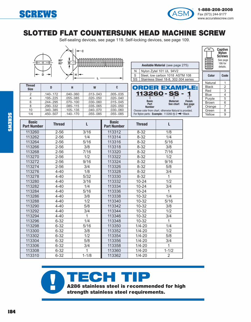
184
1-888-208-2008Fax (973) 244-9177www.accuratescrew.comSCREWS
N Nylon Zytel 101 UL 94V2S Steel, low carbon 1018 ASTM 108
SS Stainless Steel 18-8, 302-304 series
Available Material (see page 275)
SLOTTED FLAT COUNTERSUNK HEAD MACHINE SCREWSelf-sealing devices, see page 119. Self-locking devices, see page 109.
113260 2-56 3/16113262 2-56 1/4113264 2-56 5/16113266 2-56 3/8113268 2-56 7/16113270 2-56 1/2113272 2-56 9/16113274 2-56 3/4113276 4-40 1/8113278 4-40 5/32113280 4-40 3/16113282 4-40 1/4113284 4-40 5/16113286 4-40 3/8113288 4-40 1/2113290 4-40 5/8113292 4-40 3/4113294 4-40 1113296 6-32 1/4113298 6-32 5/16113300 6-32 3/8113302 6-32 1/2113304 6-32 5/8113306 6-32 3/4113308 6-32 1113310 6-32 1-1/8
113312 8-32 1/8113314 8-32 1/4113316 8-32 5/16113318 8-32 3/8113320 8-32 7/16113322 8-32 1/2113324 8-32 9/16113326 8-32 5/8113328 8-32 3/4113330 8-32 1113332 10-24 1/2113334 10-24 3/4113336 10-24 1113338 10-32 1/4113340 10-32 5/16113342 10-32 3/8113344 10-32 1/2113346 10-32 3/4113348 10-32 1113350 1/4-20 1/4113352 1/4-20 1/2113354 1/4-20 5/8113356 1/4-20 3/4113358 1/4-20 1113360 1/4-20 1-1/2113362 1/4-20 2
BasicPart Number Thread L Basic
Part Number Thread L
2 .140-.172 .040-.060 .013-.043 .005-.0354 .195-.225 .055-.085 .020-.050 .020-.0406 .244-.295 .070-.100 .030-.060 .015-.0458 .290-.332 .085-.115 .035-.065 .020-.05010 .340-.385 .105-.135 .040-.070 .030-.0601/4 .450-.507 .140-.170 .055-.085 .055-.085
ThreadSize D H W C
Natural 1Black 2Red 3Blue 4Purple 5Brown 6Orange 7Green 8Yellow 9
Color Code
ORDER EXAMPLE:- -113260
BasicPart
Number
SSMaterial:See chart
1Finish:
See page277
Choose color from chart, otherwise Natural is provided.For Nylon parts: Example: 113260-N-2 Black
CaptiveNylon
ScrewsSee page186 fordetails.
SC
RE
WS
! TECH TIPA286 stainless steel is recommended for highstrength stainless steel requirements.

185
1-888-208-2008Fax (973) 244-9177
www.accuratescrew.com SCREWS
SLOTTED OVAL COUNTERSUNK HEAD MACHINE SCREWSelf-sealing devices, see page 119. Self-locking devices, see page 109.
113364 2-56 3/16113366 2-56 1/4113368 2-56 5/16113370 2-56 3/8113372 2-56 7/16113374 2-56 1/2113376 2-56 9/16113378 2-56 3/4113380 4-40 1/8113382 4-40 5/32113384 4-40 3/16113386 4-40 1/4113388 4-40 5/16113390 4-40 3/8113392 4-40 1/2113394 4-40 5/8113396 4-40 3/4113398 4-40 1113400 6-32 1/4113402 6-32 5/16113404 6-32 3/8113406 6-32 1/2113408 6-32 5/8113410 6-32 3/4113412 6-32 1113414 6-32 1-1/8
113416 8-32 1/8113418 8-32 1/4113420 8-32 5/16113422 8-32 3/8113424 8-32 7/16113426 8-32 1/2113428 8-32 9/16113430 8-32 5/8113432 8-32 3/4113434 8-32 1113436 10-24 1/2113438 10-24 3/4113440 10-24 1113442 10-32 1/4113444 10-32 5/16113446 10-32 3/8113448 10-32 1/2113450 10-32 3/4113452 10-32 1113454 1/4-20 1/4113456 1/4-20 1/2113458 1/4-20 5/8113460 1/4-20 3/4113462 1/4-20 1113464 1/4-20 1-1/2113466 1/4-20 2
Thread LBasicPart Number Thread LBasic
Part Number
2 .140-.172 .055-.085 .013-.043 .005-.0454 .195-.225 .075-.105 .020-.050 .010-.0596 .244-.295 .095-.128 .030-.060 .015-.0748 .290-.332 .125-.155 .035-.065 .020-.08810 .340-.385 .145-.176 .040-.070 .030-.1031/4 .450-.507 .197-.235 .055-.085 .055-.136
ThreadSize D O W C
N Nylon Zytel 101 UL 94V2S Steel, low carbon 1018 ASTM 108
SS Stainless Steel 18-8, 302-304 series
Available Material (see page 275)
Natural 1Black 2Red 3Blue 4Purple 5Brown 6Orange 7Green 8Yellow 9
Color Code
ORDER EXAMPLE:- -113364
BasicPart
Number
SSMaterial:See chart
1Finish:
See page277
Choose color from chart, otherwise Natural is provided.For Nylon parts: Example: 113364-N-2 Black
CaptiveNylon
ScrewsSee page186 fordetails.
SC
RE
WS

186
1-888-208-2008Fax (973) 244-9177www.accuratescrew.comSCREWS
SC
RE
WS
113468 1/4-20 1/2113470 1/4-20 3/4113472 1/4-20 1113474 1/4-20 1-1/4113476 1/4-20 1-1/2113478 1/4-20 2113480 1/4-20 2-1/2113482 1/4-20 3113484 1/4-20 3-1/2113486 1/4-20 4113488 1/4-20 4-1/2113490 1/4-20 5113492 1/4-20 5-1/2113494 1/4-20 6
113496 5/16-18 1/2113498 5/16-18 3/4113500 5/16-18 1113502 5/16-18 1-1/4113504 5/16-18 1-1/2113506 5/16-18 2113508 5/16-18 2-1/2113510 5/16-18 3113512 5/16-18 3-1/2113514 5/16-18 4113516 5/16-18 4-1/2113518 5/16-18 5113520 5/16-18 5-1/2113522 5/16-18 6
113524 3/8-16 1/2113526 3/8-16 3/4113528 3/8-16 1113530 3/8-16 1-1/4113532 3/8-16 1-1/2113534 3/8-16 2113536 3/8-16 2-1/2113538 3/8-16 3113540 3/8-16 3-1/2113542 3/8-16 4113544 3/8-16 4-1/2113546 3/8-16 5113548 3/8-16 5-1/2113550 3/8-16 6
113552 1/2-13 1/2113554 1/2-13 3/4113556 1/2-13 1113558 1/2-13 1-1/4113560 1/2-13 1-1/2113562 1/2-13 2113564 1/2-13 2-1/2113566 1/2-13 3113568 1/2-13 3-1/2113570 1/2-13 4113572 1/2-13 4-1/2113574 1/2-13 5113576 1/2-13 5-1/2113578 1/2-13 6
113580 5/8-11 1/2113582 5/8-11 3/4113584 5/8-11 1113586 5/8-11 1-1/2113588 5/8-11 2113590 5/8-11 2-1/2113592 5/8-11 3113594 5/8-11 3-1/2113596 5/8-11 4113598 5/8-11 4-1/2113600 5/8-11 5113602 5/8-11 5-1/2113604 5/8-11 6
BasicPart
NumberThread L
BasicPart
NumberThread L
BasicPart
NumberThread L
BasicPart
NumberThread L
BasicPart
NumberThread L
HEX CAP SCREWSelf-sealing devices, see page 119. Self-locking devices, see page 109.
CAPTIVE PANEL SCREWAvailable in all head styles.
2 .061 1/83 .070 5/324 .078 5/326 .095 3/168 .120 3/1610 .130 1/41/4 .175 3/85/16 .230 1/23/8 .280 5/81/2 .390 5/85/8 .490 3/4
ThreadSize
K+1/64
G+.005
1/4 .395-.438 .440-.505 .150-.1905/16 .470-.500 .546-.577 .195-.2353/8 .544-.580 .610-.650 .226.2681/2 .725-.755 .826-.866 .302-.3645/8 .906-.950 1.033-1.115 .375-.444
N Nylon Zytel 101 UL 94V2S Steel, low carbon 1018 ASTM 108
SS Stainless Steel 18-8, 302-304 series
Available Material (see page 275)
Natural 1Black 2Red 3Blue 4Purple 5Brown 6Orange 7Green 8Yellow 9
Color Code
ORDER EXAMPLE:- -113468
BasicPart
Number
SSMaterial:See chart
1Finish:
See page277
Choose color from chart, otherwise Natural is provided.For Nylon parts: Example: 113468-N-2 Black
CaptiveNylon
ScrewsSee page186 fordetails.
ThreadSize
D E H
ORDER EXAMPLE:- - -113468
BasicPart
Number
NNylon
2Color:
See chart
CAPCaptive

187
1-888-208-2008Fax (973) 244-9177
www.accuratescrew.com SCREWS
SC
RE
WS
ThreadSize D E H W C
SLOTTED HEX CAP SCREWSelf-sealing devices, see page 119. Self-locking devices, see page 109.
KNURLED NYLON THUMB SCREWSelf-Sealing/Self-Locking Devices available, see page 109.
Available Material (see page 275)
1/4 .395-.438 .440-.505 .150-.190 .055-.085 .075-.1055/16 .470-.500 .546-.577 .195-.235 .065-.095 .095-.1253/8 .544-.580 .610-.650 .226-.268 .075-.105 .125-.1551/2 .725-.755 .826-.866 .302-.364 .085-.115 .145-.1755/8 .906-.950 1.033-1.115 .375-.444 .095-.125 .155-.185
N Nylon Zytel 101 UL 94V2S Steel, low carbon 1018 ASTM 108
SS Stainless Steel 18-8, 302-304 series
Available Material (see page 275)
Natural 1Black 2Red 3Blue 4Purple 5Brown 6Orange 7Green 8Yellow 9
Color Code
ORDER EXAMPLE:- -113606
BasicPart
Number
SSMaterial:See chart
1Finish:
See page277
Choose color from chart, otherwise Natural is provided.For Nylon parts: Example: 113606-N-2 Black
CaptiveNylon
ScrewsSee page186 fordetails.
113606 1/4-20 1/2113608 1/4-20 3/4113610 1/4-20 1113612 1/4-20 1-1/4113614 1/4-20 1-1/2113616 1/4-20 2113618 1/4-20 2-1/2113620 1/4-20 3113622 1/4-20 3-1/2113624 1/4-20 4113626 1/4-20 4-1/2113628 1/4-20 5113630 1/4-20 5-1/2113632 1/4-20 6
113634 5/16-18 1/2113636 5/16-18 3/4113638 5/16-18 1113640 5/16-18 1-1/4113642 5/16-18 1-1/2113644 5/16-18 2113646 5/16-18 2-1/2113648 5/16-18 3113650 5/16-18 3-1/2113652 5/16-18 4113654 5/16-18 4-1/2113656 5/16-18 5113658 5/16-18 5-1/2113660 5/16-18 6
113662 3/8-16 1/2113664 3/8-16 3/4113666 3/8-16 1113668 3/8-16 1-1/4113670 3/8-16 1-1/2113672 3/8-16 2113674 3/8-16 2-1/2113676 3/8-16 3113678 3/8-16 3-1/2113680 3/8-16 4113682 3/8-16 4-1/2113684 3/8-16 5113686 3/8-16 5-12113688 3/8-16 6
113690 1/2-13 1/2113692 1/2-13 3/4113694 1/2-13 1113696 1/2-13 1-1/4113698 1/2-13 1-1/2113700 1/2-13 2113702 1/2-13 2-1/2113704 1/2-13 3113706 1/2-13 3-1/2113708 1/2-13 4113710 1/2-13 4-1/2113712 1/2-13 5113714 1/2-13 5-1/2113716 1/2-13 6
113718 5/8-11 1/2113720 5/8-11 3/4113722 5/8-11 1113724 5/8-11 1-1/2113726 5/8-11 2113728 5/8-11 2-1/2113730 5/8-11 3113732 5/8-11 3-1/2113734 5/8-11 4113736 5/8-11 4-1/2113738 5/8-11 5113740 5/8-11 5-1/2113742 5/8-11 6
BasicPart
NumberThread L
BasicPart
NumberThread L
BasicPart
NumberThread L
BasicPart
NumberThread L
BasicPart
NumberThread L
Natural 1Black 2Red 3Blue 4Purple 5Brown 6Orange 7Green 8Yellow 9
Color Code
ORDER EXAMPLE:- -113744
BasicPart
Number
NNylon
2Color:
See chart
Choose color from chart, otherwise Natural is provided.
113744 4-40 1/4113746 4-40 3/8113748 4-40 1/2113750 4-40 3/4113752 6-32 1/4113754 6-32 3/8113756 6-32 1/2113758 6-32 3/4
113760 6-32 1113762 8-32 3/16113764 8-32 3/8113766 8-32 1/2113768 8-32 3/4113770 8-32 1113772 10-24 1/2113774 10-24 3/4
113776 10-24 1113778 10-24 1-1/4113780 10-32 3/8113782 10-32 1/2113784 10-32 3/4113786 10-32 1113788 1/4-20 1/2113790 1/4-20 3/4
Basic PartNumber Thread L Basic Part
Number Thread L Basic PartNumber Thread L
ThreadSize
D± .015
B± .015
C± .015
4-40 .300 .280 .1206-32 .360 .275 .1258-32 .425 .305 .14010-24 .425 .325 .14010-32 .425 .325 .1401/4-20 .540 .365 .155N Nylon, Zytel 101 UL 94V2

188
1-888-208-2008Fax (973) 244-9177www.accuratescrew.comSCREWS
SC
RE
WS
SLOTTED SET SCREW
2 .055 .035 .018 .0204 .075 .045 .020 .0256 .100 .055 .025 .0308 .120 .055 .028 .03510 .150 .060 .035 .0501/4 .175 .080 .040 .060
ThreadSize
D ± .015
H ± .015
W ± .015
C ± .015
N Nylon Zytel 101 UL 94V2S Steel, low carbon 1018 ASTM 108
SS Stainless Steel 18-8, 302-304 series
Available Material (see page 275)
Natural 1Black 2Red 3Blue 4Purple 5Brown 6Orange 7Green 8Yellow 9
Color Code
ORDER EXAMPLE:- -112636
BasicPart
Number
SSMaterial:See chart
12Finish:
See page277
Choose color from chart, otherwise Natural is provided.For Nylon parts: Example: 112636-N-2 Black
112636 2-56 3/32112638 2-56 1/8112640 2-56 3/16112642 2-56 1/4112644 2-56 9/32112646 2-56 5/16112648 2-56 3/8112650 2-56 7/16112652 2-56 1/2112654 2-56 5/8112656 2-56 3/4112658 2-56 1112660 4-40 1/8112662 4-40 5/32112664 4-40 3/16112666 4-40 1/4112668 4-40 9/32112670 4-40 5/16112672 4-40 3/8112674 4-40 7/16112676 4-40 1/2112678 4-40 9/16112680 4-40 5/8112682 4-40 11/16112684 4-40 3/4112686 4-40 7/8112688 4-40 1112690 4-40 1-1/8112692 4-40 1-1/4112694 6-32 3/32112696 6-32 1/8112698 6-32 3/16112700 6-32 1/4
112702 6-32 5/16112704 6-32 3/8112706 6-32 7/16112708 6-32 1/2112710 6-32 5/8112712 6-32 3/4112714 6-32 1112716 6-32 1-1/8112718 6-32 1-1/4112720 6-32 1-1/2112722 6-32 1-3/4112724 6-40 3/8112726 8-32 1/8112728 8-32 3/16112730 8-32 1/4112732 8-32 5/16112734 8-32 3/8112736 8-32 7/16112738 8-32 1/2112740 8-32 5/8112742 8-32 3/4112744 8-32 7/8112746 8-32 1112748 8-32 1-1/8112750 8-32 1-1/4112752 8-32 1-3/8112754 8-32 1-1/2112756 8-32 1-3/4112758 8-32 2112760 10-24 1/8112762 10-24 3/16112764 10-24 1/4112766 10-24 5/16
112768 10-24 3/8112770 10-24 1/2112772 10-24 5/8112774 10-24 3/4112776 10-24 1112778 10-24 1-1/4112780 10-24 1-1/2112782 10-32 1/8112784 10-32 3/16112786 10-32 1/4112788 10-32 5/16112790 10-32 3/8112792 10-32 1/2112794 10-32 5/8112796 10-32 3/4112798 10-32 7/8112800 10-32 1112802 10-32 1-1/4112804 10-32 1-1/2112806 10-32 2112808 1/4-20 1/4112810 1/4-20 5/16112812 1/4-20 3/8112814 1/4-20 1/2112816 1/4-20 5/8112818 1/4-20 3/4112820 1/4-20 7/8112822 1/4-20 1112824 1/4-20 1-1/4112826 1/4-20 1-1/2112828 1/4-20 1-3/4112830 1/4-20 2
Basic PartNumber Thread L Basic Part
Number Thread L Basic PartNumber Thread L

189
1-888-208-2008Fax (973) 244-9177
www.accuratescrew.com SCREWS
SC
RE
WS
SOCKET SET SCREW
W
4 .050 .0706 .062 .0808 .078 .09010 .094 .1001/4 .125 .1255/16 .156 .1563/8 .188 .1881/2 .250 .2505/8 .312 .312
ThreadSize
W ± .015
C ± .015
N Nylon Zytel 101 UL 94V2S Steel, low carbon 1018 ASTM 108
SS Stainless Steel 18-8, 302-304 series
Available Material (see page 275)
Natural 1Black 2Red 3Blue 4Purple 5Brown 6Orange 7Green 8Yellow 9
Color Code
ORDER EXAMPLE:- -113060
BasicPart
Number
SSMaterial:See chart
12Finish:
See page277
Choose color from chart, otherwise Natural is provided.For Nylon parts: Example: 113060-N-2 Black
113060 4-40 1/8113062 4-40 9/64113064 4-40 5/32113066 4-40 3/16113068 4-40 1/4113070 4-40 9/32113072 4-40 5/16113074 4-40 3/8113076 4-40 7/16113078 4-40 1/2113080 4-40 9/16113082 4-40 5/8113084 4-40 11/16113086 4-40 3/4113088 4-40 7/8113090 4-40 1113092 4-40 1-1/8113094 4-40 1-1/4113096 6-32 3/32113098 6-32 1/8113100 6-32 3/16113102 6-32 1/4113104 6-32 5/16113106 6-32 3/8113108 6-32 7/16113110 6-32 1/2113112 6-32 5/8113114 6-32 3/4113116 6-32 1113118 6-32 1-1/8113120 6-32 1-1/4113122 6-32 1-1/2113124 6-32 1-3/4113126 6-40 3/8
113128 8-32 1/8113130 8-32 3/16113132 8-32 1/4113134 8-32 5/16113136 8-32 3/8113138 8-32 7/16113140 8-32 1/2113142 8-32 5/8113144 8-32 3/4113146 8-32 1113148 8-32 1-1/8113150 8-32 1-1/4113152 8-32 1-3/8113154 8-32 1-1/2113156 8-32 1-3/4113158 8-32 2113160 10-24 1/8113162 10-24 3/16113164 10-24 1/4113166 10-24 5/16113168 10-24 3/8113170 10-24 1/2113172 10-24 5/8113174 10-24 3/4113176 10-24 1113178 10-24 1-1/4113180 10-24 1-1/2113182 10-32 1/8113184 10-32 3/16113186 10-32 1/4113188 10-32 5/16113190 10-32 3/8113192 10-32 1/2113194 10-32 5/8
113196 10-32 3/4113198 10-32 7/8113200 10-32 1113202 10-32 1-1/4113204 10-32 1-1/2113206 10-32 2113208 1/4-20 1/4113210 1/4-20 5/16113212 1/4-20 3/8113214 1/4-20 1/2113216 1/4-20 5/8113218 1/4-20 3/4113220 1/4-20 7/8113222 1/4-20 1113224 1/4-20 1-1/4113226 1/4-20 1-1/2113228 1/4-20 1-3/4113230 1/4-20 2113232 5/16-18 1/2113234 5/16-18 3/4113236 5/16-18 1113238 3/8-16 1/2113240 3/8-16 3/4113242 3/8-16 1113244 1/2-13 1/2113246 1/2-13 3/4113248 1/2-13 1113250 1/2-13 1-1/4113252 5/8-11 1/2113254 5/8-11 3/4113256 5/8-11 1113258 5/8-11 1-1/2
Basic PartNumber Thread L
± .015Basic PartNumber Thread L
± .015Basic PartNumber Thread L
± .015

190
1-888-208-2008Fax (973) 244-9177www.accuratescrew.comRETAINERS
RE
TA
INE
RS
METHOD OF INSTALLATION Series 400000 Retainers Only
Recommended Diameters
.198 .188
.228 .218
.280 .270
.366 .356
.414 .404
.479 .469
ShankDiameter
Recommended Panel Hole Diameter
+.002–.000
.188 .191
.218 .221
.250 .257
.270 .272
.356 .359
.404 .407
.433 .437
RetainerShank Diameter
XDrill or Punch
Countersink formula: A = X + .045 minimum or .078 maximum
METHOD OF INSTALLATION Series 500000, 550000, 600000, 650000,
700000 and 750000 Retainers OnlySee page 45 for installation information.
Drill hole to press in.
! TECH TIPFor shank diameters .270 and belowstart with a .045 min when calculatingthe diameter (“A”) of the countersink.

191
1-888-208-2008Fax (973) 244-9177
www.accuratescrew.com RETAINERS
400001 4-40 .048 - .072 1/4 .198 .150 .050 .200 1/4 .164400002 4-40 .074 - .109 1/4 .198 .150 .080 .170 1/4 .164400003 4-40 .119 - .156 1/4 .198 .150 .125 .125 1/4 .164400004 6-32 .048 - .072 1/4 .198 .150 .050 .262 5/16 .210400005 6-32 .074 - .109 1/4 .198 .150 .080 .232 5/16 .210400006 6-32 .119 - .156 1/4 .198 .150 .125 .187 5/16 .210400007 6-32 .188 1/4 .198 .150 .188 .125 5/16 .210400008 8-32 .048 - .072 5/16 .228 .188 .050 .262 5/16 .208400009 8-32 .074 - .109 5/16 .228 .188 .080 .232 5/16 .208400010 8-32 .119 - .156 5/16 .228 .188 .125 .187 5/16 .208400011 8-32 .188 5/16 .228 .188 .188 .124 5/16 .208400012 10-24 .048 - .072 3/8 .280 .228 .050 .325 3/8 .236400013 10-24 .074 - .109 3/8 .280 .228 .080 .295 3/8 .236400014 10-24 .119 - .156 3/8 .280 .228 .125 .250 3/8 .236400015 10-24 .188 3/8 .280 .228 .188 .187 3/8 .236400016 10-24 .250 3/8 .280 .228 .250 .125 3/8 .236400017 10-32 .048 - .072 3/8 .280 .228 .050 .325 3/8 .236400018 10-32 .074 - .109 3/8 .280 .228 .080 .295 3/8 .236400019 10-32 .119 - .156 3/8 .280 .228 .125 .250 3/8 .236400021 10-32 .188 3/8 .280 .228 .188 .187 3/8 .236400022 10-32 .250 3/8 .280 .228 .250 .125 3/8 .236400023 1/4-20 .048 - .072 1/2 .366 .295 .050 .387 7/16 .292400024 1/4-20 .074 - .109 1/2 .366 .295 .080 .357 7/16 .292400025 1/4-20 .119 - .156 1/2 .366 .295 .125 .312 7/16 .292400026 1/4-20 .188 1/2 .366 .295 .188 .249 7/16 .292400027 1/4-20 .250 1/2 .366 .295 .250 .187 7/16 .292400028 1/4-28 .048 - .072 1/2 .366 .295 .050 .387 7/16 .292400029 1/4-28 .074 - .109 1/2 .366 .295 .080 .357 7/16 .292400031 1/4-28 .119 - .156 1/2 .366 .295 .125 .312 7/16 .292400032 1/4-28 .188 1/2 .366 .295 .188 .249 7/16 .292400033 1/4-28 .250 1/2 .366 .295 .250 .187 7/16 .292400034 5/16-18 .048 - .072 5/8 .414 .347 .050 .450 1/2 .358400035 5/16-18 .074 - .109 5/8 .414 .347 .080 .420 1/2 .358400036 5/16/18 .119 - .156 5/8 .414 .347 .125 .375 1/2 .358400037 5/16-18 .188 5/8 .414 .347 .188 .312 1/2 .358400038 5/16-18 .250 5/8 .414 .347 .250 .250 1/2 .358400039 3/8-16 .074 - .109 3/4 .479 .406 .080 .482 9/16 .418400041 3/8-16 .119 - .156 3/4 .479 .406 .125 .437 9/16 .418400042 3/8-16 .188 3/4 .479 .406 .188 .374 9/16 .418400043 3/8-16 .250 3/4 .479 .406 .250 .312 9/16 .418
BasicPart
Number
A+.004
PanelThicknessThread D
+.005C
+.004-.001
B+.002
F+.010
G+.005
E+.005
SERIES 400000 RETAINERFor Captive Screws, see pages 113-156.
A AluminumB BrassS Steel
SS Stainless Steel
Available Material (see page 275)
For method of installation, see page 190.ORDER EXAMPLE:
- -400001BasicPart
Number
SMaterial:See chart
12Finish:
See page277
If any one dimension or tolerance change is required, add toend of part number. EXAMPLE: 400001-SS-12 (A=1/2)
RE
TA
INE
RS

192
1-888-208-2008Fax (973) 244-9177www.accuratescrew.comRETAINERS
RE
TA
INE
RS
SERIES 500000 RETAINERFor Captive Screws, see pages 113-156.
500001 4-40 .052 - .067 9/32 .250 .210 .062 .312 3/8 .263500002 4-40 .084 - .099 9/32 .250 .210 .093 .281 3/8 .263500003 4-40 .109 - .140 9/32 .250 .210 .125 .250 3/8 .263500004 6-32 .052 - .067 9/32 .250 .210 .062 .313 3/8 .265500005 6-32 .084 - .099 9/32 .250 .210 .093 .282 3/8 .265500006 6-32 .109 - .140 9/32 .250 .210 .125 .250 3/8 .265500007 8-32 .052 - .067 17/32 .433 .386 .062 .500 9/16 .388500008 8-32 .084 - .099 17/32 .433 .386 .093 .469 9/16 .388500009 8-32 .109 - .140 17/32 .433 .386 .125 .437 9/16 .388500010 8-32 .171 - .203 17/32 .433 .386 .187 .375 9/16 .388500011 8-32 .234 - .265 17/32 .433 .386 .250 .312 9/16 .388500012 10-24 .052 - .067 17/32 .433 .386 .062 .500 9/16 .395500013 10-24 .084 - .099 17/32 .433 .386 .093 .469 9/16 .395500014 10-24 .109 - .140 17/32 .433 .386 .125 .437 9/16 .395500015 10-24 .171 - .203 17/32 .433 .386 .187 .375 9/16 .395500016 10-24 .234 - .265 17/32 .433 .386 .250 .312 9/16 .395500017 10-32 .052 - .067 17/32 .433 .386 .062 .500 9/16 .395500018 10-32 .084 - .099 17/32 .433 .386 .093 .469 9/16 .395500019 10-32 .109 - .140 17/32 .433 .386 .125 .437 9/16 .395500020 10-32 .171 - .203 17/32 .433 .386 .187 .375 9/16 .395500021 10-32 .234 - .265 17/32 .433 .386 .250 .312 9/16 .395500022 12-24 .052 - .067 17/32 .433 .386 .062 .500 9/16 .396500023 12-24 .084 - .099 17/32 .433 .386 .093 .469 9/16 .396500024 12-24 .109 - .140 17/32 .433 .386 .125 .437 9/16 .396500025 12-24 .171 - .203 17/32 .433 .386 .187 .375 9/16 .396500026 12-24 .234 - .265 17/32 .433 .386 .250 .312 9/16 .396500027 1/4-20 .052 - .067 17/32 .433 .386 .062 .500 9/16 .403500028 1/4-20 .084 - .099 17/32 .433 .386 .093 .469 9/16 .403500029 1/4-20 .109 - .140 17/32 .433 .386 .125 .437 9/16 .403500030 1/4-20 .171 - .203 17/32 .433 .386 .187 .375 9/16 .403500031 1/4-20 .234 - .265 17/32 .433 .386 .250 .312 9/16 .403500032 1/4-28 .052 - .067 17/32 .433 .386 .062 .500 9/16 .403500033 1/4-28 .084 - .099 17/32 .433 .386 .093 .469 9/16 .403500034 1/4-28 .109 - .140 17/32 .433 .386 .125 .437 9/16 .403500035 1/4-28 .171 - .203 17/32 .433 .386 .187 .375 9/16 .403500036 1/4-28 .234 - .265 17/32 .433 .386 .250 .312 9/16 .403
BasicPart
Number
A+.004
PanelThicknessThread
D+.005
C+.004-.001
B+.000-.003
F+.010
G+.005-.010
E+.005
A AluminumB BrassS Steel
SS Stainless Steel
Available Material (see page 275)
For method of installation, see page 190.
ORDER EXAMPLE:- -500001
BasicPart
Number
SMaterial:See chart
1Finish:
See page277

193
1-888-208-2008Fax (973) 244-9177
www.accuratescrew.com RETAINERS
SERIES 550000 RETAINER
BasicPart
Number
A+.004
PanelThickness
ThreadD
+.005-.000
C+.004-.001
B+.000-.003
F+.005
G+.010
E+.005
550001 4-40 .052/ .067 9/32 .250 .210 .192 .062 .375 7/16 .263550002 4-40 .084/ .099 9/32 .250 .210 .192 .093 .344 7/16 .263550003 4-40 .109/ .140 9/32 .250 .210 .192 .125 .312 7/16 .263550004 6-32 .052/ .067 9/32 .250 .210 .192 .062 .375 7/16 .266550005 6-32 .084/ .099 9/32 .250 .210 .192 .093 .344 7/16 .266550006 6-32 .109/ .140 9/32 .250 .210 .192 .125 .312 7/16 .266550007 8-32 .052/ .067 17/32 .433 .386 .312 .062 .563 5/8 .388550008 8-32 .084/ .099 17/32 .433 .386 .312 .093 .532 5/8 .388550009 8-32 .109/ .140 17/32 .433 .386 .312 .125 .500 5/8 .388550010 8-32 .171/ .203 17/32 .433 .386 .312 .187 .438 5/8 .388550011 8-32 .234/ .265 17/32 .433 .386 .312 .250 .375 5/8 .388550012 10-24 .052/ .067 17/32 .433 .386 .312 .062 .563 5/8 .393550013 10-24 .084/ .099 17/32 .433 .386 .312 .093 .532 5/8 .393550014 10-24 .109/ .140 17/32 .433 .386 .312 .125 .500 5/8 .393550015 10-24 .171/ .203 17/32 .433 .386 .312 .187 .438 5/8 .393550016 10-24 .234/ .265 17/32 .433 .386 .312 .250 .375 5/8 .393550017 10-32 .052/ .067 17/32 .433 .386 .312 .062 .563 5/8 .393550018 10-32 .084/ .099 17/32 .433 .386 .312 .093 .532 5/8 .393550019 10-32 .109/ .140 17/32 .433 .386 .312 .125 .500 5/8 .393550020 10-32 .171/ .203 17/32 .433 .386 .312 .187 .438 5/8 .393550021 10-32 .234/ .265 17/32 .433 .386 .312 .250 .375 5/8 .393550022 12-24 .052/ .067 17/32 .433 .386 .312 .062 .563 5/8 .397550023 12-24 .084/ .099 17/32 .433 .386 .312 .093 .532 5/8 .397550024 12-24 .109/ .140 17/32 .433 .386 .312 .125 .500 5/8 .397550025 12-24 .171/ .203 17/32 .433 .386 .312 .187 .438 5/8 .397550028 12-24 .234/ .265 17/32 .433 .386 .312 .250 .375 5/8 .397550029 1/4-20 .052/ .067 17/32 .433 .386 .312 .062 .563 5/8 .405550030 1/4-20 .084/ .099 17/32 .433 .386 .312 .093 .532 5/8 .405550031 1/4-20 .109/ .140 17/32 .433 .386 .312 .125 .500 5/8 .405550032 1/4-20 .171/ .203 17/32 .433 .386 .312 .187 .438 5/8 .405550033 1/4-20 .234/ .265 17/32 .433 .386 .312 .250 .375 5/8 .405550034 1/4-28 .084/ .099 17/32 .433 .386 .312 .093 .532 5/8 .405550035 1/4-28 .109/ .140 17/32 .433 .386 .312 .125 .500 5/8 .405550036 1/4-28 .171/ .203 17/32 .433 .386 .312 .187 .438 5/8 .405550037 1/4-28 .234/ .265 17/32 .433 .386 .312 .250 .375 5/8 .405
H+.005-.010
Choose appropriate screwfrom pages 113-114.
A AluminumB BrassS Steel
SS Stainless Steel
Available Material (see page 275)
For method of installation, see page 190.
ORDER EXAMPLE:- -550001
BasicPart
Number
SMaterial:See chart
1Finish:
See page277
Captive Panel Screw and Spring must be ordered separately.
(see page 198)
RE
TA
INE
RS

194
1-888-208-2008Fax (973) 244-9177www.accuratescrew.comRETAINERS
RE
TA
INE
RS
SERIES 600000 RETAINER
600001 4-40 .052/ .067 9/32 .250 .210 .125 .062 .312 3/8 .299600002 4-40 .084/ .099 9/32 .250 .210 .125 .093 .281 3/8 .299600003 4-40 .109/ .140 9/32 .250 .210 .125 .125 .250 3/8 .299600004 6-32 .052/ .067 9/32 .250 .210 .152 .062 .313 3/8 .304600007 6-32 .084/ .099 9/32 .250 .210 .152 .093 .282 3/8 .304600008 6-32 .109/ .140 9/32 .250 .210 .152 .125 .250 3/8 .304600009 8-32 .052/ .067 17/32 .433 .386 .177 .062 .500 9/16 .447600010 8-32 .084/ .099 17/32 .433 .386 .177 .093 .469 9/16 .447600011 8-32 .109/ .140 17/32 .433 .386 .177 .125 .437 9/16 .447600012 8-32 .171/ .203 17/32 .433 .386 .177 .187 .375 9/16 .447600013 8-32 .234/ .265 17/32 .433 .386 .177 .250 .312 9/16 .447600014 10-24 .052/ .067 17/32 .433 .386 .203 .062 .500 9/16 .464600015 10-24 .084/ .099 17/32 .433 .386 .203 .093 .469 9/16 .464600018 10-24 .109/ .140 17/32 .433 .386 .203 .125 .437 9/16 .464600019 10-24 .171/ .203 17/32 .433 .386 .203 .187 .375 9/16 .464600020 10-24 .234/ .265 17/32 .433 .386 .203 .250 .312 9/16 .464600021 10-32 .052/ .067 17/32 .433 .386 .203 .062 .500 9/16 .464600022 10-32 .084/ .099 17/32 .433 .386 .203 .093 .469 9/16 .464600023 10-32 .109/ .140 17/32 .433 .386 .203 .125 .437 9/16 .464600026 10-32 .171/ .203 17/32 .433 .386 .203 .187 .375 9/16 .464600027 10-32 .234/ .265 17/32 .433 .386 .203 .250 .312 9/16 .464600028 12-24 .052/ .067 17/32 .433 .386 .228 .062 .500 9/16 .459600029 12-24 .084/ .099 17/32 .433 .386 .228 .093 .469 9/16 .459600030 12-24 .109/ .140 17/32 .433 .386 .228 .125 .437 9/16 .459600031 12-24 .171/ .203 17/32 .433 .386 .228 .187 .375 9/16 .459600032 12-24 .234/ .265 17/32 .433 .386 .228 .250 .312 9/16 .459600033 1/4-20 .052/ .067 17/32 .433 .386 .257 .062 .500 9/16 .475600034 1/4-20 .084/ .099 17/32 .433 .386 .257 .093 .469 9/16 .475600035 1/4-20 .109/ .140 17/32 .433 .386 .257 .125 .437 9/16 .475600036 1/4-20 .171/ .203 17/32 .433 .386 .257 .187 .375 9/16 .475600037 1/4-20 .234/ .265 17/32 .433 .386 .257 .250 .312 9/16 .475600038 1/4-28 .052/ .067 17/32 .433 .386 .257 .062 .500 9/16 .475600039 1/4-28 .084/ .099 17/32 .433 .386 .257 .093 .469 9/16 .475600040 1/4-28 .109/ .140 17/32 .433 .386 .257 .125 .437 9/16 .475600041 1/4-28 .171/ .203 17/32 .433 .386 .257 .187 .375 9/16 .475600042 1/4-28 .234/ .265 17/32 .433 .386 .257 .250 .312 9/16 .475
BasicPart
Number
A+.004
PanelThickness
ThreadD
+.004-.001
C+.004-.001
B+.000-.003
F+.005
G+.010
E+.005
H+.005-.010
See page 147.
Choose appropriate screwfrom pages 113, 119.
A AluminumB BrassS Steel
SS Stainless Steel
Available Material (see page 275)
For method of installation, see page 190.
ORDER EXAMPLE:- -600001
BasicPart
Number
SMaterial:See chart
1Finish:
See page277
Captive Panel Screw and Retainer Ring must be ordered separately.

195
1-888-208-2008Fax (973) 244-9177
www.accuratescrew.com RETAINERS
SERIES 650000 RETAINER
BasicPart
Number
A+.004
PanelThickness
ThreadD
+.005-.000
C+.004-.001
B+.000-.003
F+.005
G+.010
E+.005
H+.005-.010
650001 4-40 .052/ .067 9/32 .250 .210 .192 .062 .375 7/16 .299 .125650002 4-40 .084/ .099 9/32 .250 .210 .192 .093 .344 7/16 .299 .125650003 4-40 .109/ .140 9/32 .250 .210 .192 .125 .312 7/16 .299 .125650004 6-32 .052/ .067 9/32 .250 .210 .192 .062 .375 7/16 .305 .150650005 6-32 .084/ .099 9/32 .250 .210 .192 .093 .344 7/16 .305 .150650006 6-32 .109/ .140 9/32 .250 .210 .192 .125 .312 7/16 .305 .150650007 8-32 .052/ .067 17/32 .433 .386 .312 .062 .563 5/8 .427 .175650008 8-32 .084/ .099 17/32 .433 .386 .312 .093 .532 5/8 .427 .175650009 8-32 .109/ .140 17/32 .433 .386 .312 .125 .500 5/8 .427 .175650010 8-32 .171/ .203 17/32 .433 .386 .312 .187 .438 5/8 .427 .175650011 8-32 .234/ .265 17/32 .433 .386 .312 .250 .375 5/8 .427 .175650012 10-24 .052/ .067 17/32 .433 .386 .312 .062 .563 5/8 .432 .203650013 10-24 .084/ .099 17/32 .433 .386 .312 .093 .532 5/8 .432 .203650014 10-24 .109/ .140 17/32 .433 .386 .312 .125 .500 5/8 .432 .203650015 10-24 .171/ .203 17/32 .433 .386 .312 .187 .438 5/8 .432 .203650016 10-24 .234/ .265 17/32 .433 .386 .312 .250 .375 5/8 .432 .203650017 10-32 .052/ .067 17/32 .433 .386 .312 .062 .563 5/8 .432 .203650018 10-32 .084/ .099 17/32 .433 .386 .312 .093 .532 5/8 .432 .203650019 10-32 .109/ .140 17/32 .433 .386 .312 .125 .500 5/8 .432 .203650020 10-32 .171/ .203 17/32 .433 .386 .312 .187 .438 5/8 .432 .203650021 10-32 .234/ .265 17/32 .433 .386 .312 .250 .375 5/8 .432 .203650022 12-24 .052/ .067 17/32 .433 .386 .312 .062 .563 5/8 .438 .228650023 12-24 .084/ .099 17/32 .433 .386 .312 .093 .532 5/8 .438 .228650024 12-24 .109/ .140 17/32 .433 .386 .312 .125 .500 5/8 .438 .228650025 12-24 .171/ .203 17/32 .433 .386 .312 .187 .438 5/8 .438 .228650026 12-24 .234/ .265 17/32 .433 .386 .312 .250 .375 5/8 .438 .228650027 1/4-20 .052/ .067 17/32 .433 .386 .312 .062 .563 5/8 .445 .257650028 1/4-20 .084/ .099 17/32 .433 .386 .312 .093 .532 5/8 .445 .257650029 1/4-20 .109/ .140 17/32 .433 .386 .312 .125 .500 5/8 .445 .257650030 1/4-20 .171/ .203 17/32 .433 .386 .312 .187 .438 5/8 .445 .257650031 1/4-20 .234/ .265 17/32 .433 .386 .312 .250 .375 5/8 .445 .257650032 1/4-28 .052/ .067 17/32 .433 .386 .312 .062 .563 5/8 .445 .257650033 1/4-28 .084/ .099 17/32 .433 .386 .312 .093 .532 5/8 .445 .257650034 1/4-28 .109/ .140 17/32 .433 .386 .312 .125 .500 5/8 .445 .257650035 1/4-28 .171/ .203 17/32 .433 .386 .312 .187 .438 5/8 .445 .257650036 1/4-28 .234/ .265 17/32 .433 .386 .312 .250 .375 5/8 .445 .257
J+.004-.001
See page 197.
See page 147.
Choose appropriate screwfrom pages 113-114.
A AluminumB BrassS Steel
SS Stainless Steel
Available Material (see page 275)
For method of installation, see page 190.
ORDER EXAMPLE:- -650001
BasicPart
Number
SMaterial:See chart
1Finish:
See page277
Captive Panel Screw and Retainer Ring mustbe ordered separately.
RE
TA
INE
RS

196
1-888-208-2008Fax (973) 244-9177www.accuratescrew.comRETAINERS
RE
TA
INE
RS
SERIES 700000 RETAINER - Small ProfileFor Captive Screws, see pages 113-156.
750001 6-32 .109/ .140 9/16 .406 .343 .165 .312 .477 .242750002 6-32 .171/ .203 9/16 .406 .343 .230 .312 .542 .307750003 6-32 .234/ .265 9/16 .406 .343 .290 .312 .602 .367750004 8-32 .109/ .140 9/16 .406 .343 .165 .312 .477 .248750005 8-32 .171/ .203 9/16 .406 .343 .230 .312 .542 .315750006 8-32 .234/ .265 9/16 .406 .343 .290 .312 .602 .373750007 10-32 .109/ .140 9/16 .406 .343 .165 .312 .477 .252750008 10-32 .171/ .203 9/16 .406 .343 .230 .312 .542 .318750009 10-32 .234/ .265 9/16 .406 .343 .290 .312 .602 .378750010 12-24 .109/ .140 9/16 .406 .343 .165 .312 .477 .256750011 12-24 .171/ .203 9/16 .406 .343 .230 .312 .542 .321750012 12-24 .234/ .265 9/16 .406 .343 .290 .312 .602 .381750013 1/4-20 .109/ .140 9/16 .406 .343 .165 .312 .477 .261750014 1/4-20 .171/ .203 9/16 .406 .343 .230 .312 .542 .326750015 1/4-20 .234/ .265 9/16 .406 .343 .290 .312 .602 .386
BasicPart
Number
A+.004
PanelThickness
ThreadD
+.005C
+.004-.001
B+.000-.003
F+.005
G+.005-.010
E+.005
BasicPart
Number
A+.004
PanelThickness
ThreadD
+.005C
+.004-.001
B+.000-.003
F+.010
G+.005-.010
E+.005
700001 4-40 .052/ .067 1/4 .188 .150 .062 .188 1/4 .161700002 4-40 .084/ .099 1/4 .188 .150 .093 .157 1/4 .161700003 4-40 .109/ .140 1/4 .188 .150 .125 .125 1/4 .161700004 6-32 .052/ .067 1/4 .188 .150 .062 .250 5/16 .210700005 6-32 .084/ .099 1/4 .188 .150 .093 .219 5/16 .210700006 6-32 .109/ .140 1/4 .188 .150 .125 .188 5/16 .210700007 8-32 .052/ .067 3/8 .218 .188 .062 .250 5/16 .210700008 8-32 .084/ .099 3/8 .218 .188 .093 .219 5/16 .210700009 8-32 .109/ .140 3/8 .218 .188 .125 .187 5/16 .210700010 8-32 .171/ .203 3/8 .218 .188 .187 .125 5/16 .210700011 10-24 .052/ .067 3/8 .270 .228 .062 .313 3/8 .236700012 10-24 .084/ .099 3/8 .270 .228 .093 .282 3/8 .236700013 10-24 .109/ .140 3/8 .270 .228 .125 .250 3/8 .236700014 10-24 .171/ .203 3/8 .270 .228 .187 .188 3/8 .236700015 10-24 .234/ .265 3/8 .270 .228 .250 .125 3/8 .236700016 10-32 .052/ .067 3/8 .270 .228 .062 .313 3/8 .236700017 10-32 .084/ .099 3/8 .270 .228 .093 .282 3/8 .236700018 10-32 .109/ .140 3/8 .270 .228 .125 .250 3/8 .236700019 10-32 .171/ .203 3/8 .270 .228 .187 .188 3/8 .236700020 10-32 .234/ .265 3/8 .270 .228 .250 .125 3/8 .236700021 12-24 .052/ .067 3/8 .270 .228 .062 .313 3/8 .239700022 12-24 .084/ .099 3/8 .270 .228 .093 .282 3/8 .239700023 12-24 .109/ .140 3/8 .270 .228 .125 .250 3/8 .239700024 12-24 .171/ .203 3/8 .270 .228 .187 .188 3/8 .239700025 12-24 .234/ .265 3/8 .270 .228 .250 .125 3/8 .239700026 1/4-20 .052/ .067 1/2 .356 .295 .062 .375 7/16 .295700027 1/4-20 .084/ .099 1/2 .356 .295 .093 .344 7/16 .295700028 1/4-20 .109/ .140 1/2 .356 .295 .125 .312 7/16 .295700029 1/4-20 .171/ .203 1/2 .356 .295 .187 .250 7/16 .295700030 1/4-20 .234/ .265 1/2 .356 .295 .250 .187 7/16 .295700031 1/4-28 .052/ .067 1/2 .356 .295 .062 .375 7/16 .295700032 1/4-28 .084/ .099 1/2 .356 .295 .093 .344 7/16 .295700033 1/4-28 .109/ .140 1/2 .356 .295 .125 .312 7/16 .295700034 1/4-28 .171/ .203 1/2 .356 .295 .187 .250 7/16 .295700035 1/4-28 .234/ .265 1/2 .356 .295 .250 .187 7/16 .295700036 5/16-24 .052/ .067 1/2 .404 .343 .062 .375 7/16 .297700037 5/16-24 .084/ .099 1/2 .404 .343 .093 .344 7/16 .297700038 5/16-24 .109/ .140 1/2 .404 .343 .125 .312 7/16 .297700039 5/16-24 .171/ .203 1/2 .404 .343 .187 .250 7/16 .297700040 5/16-24 .234/ .265 1/2 .404 .343 .250 .187 7/16 .297
SERIES 750000 RETAINER - Heavy Duty
A AluminumB BrassS Steel
SS Stainless Steel
Available Material (see page 275)
For method of installation, see page 190.
ORDER EXAMPLE:- -700001
BasicPart
Number
SMaterial:See chart
1Finish:
See page277
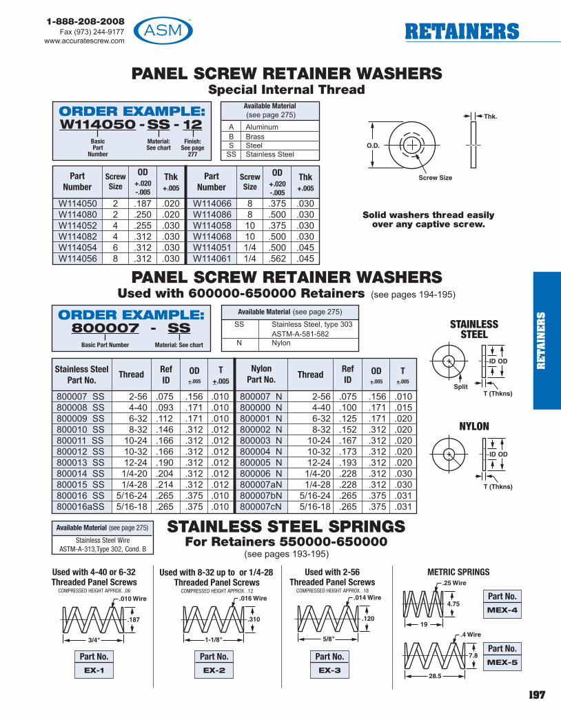
197
1-888-208-2008Fax (973) 244-9177
www.accuratescrew.com RETAINERS
STAINLESS STEEL SPRINGSFor Retainers 550000-650000
(see pages 193-195)
W114050 2 .187 .020W114080 2 .250 .020W114052 4 .255 .030W114082 4 .312 .030W114054 6 .312 .030W114056 8 .312 .030
W114066 8 .375 .030W114086 8 .500 .030W114058 10 .375 .030W114068 10 .500 .030W114051 1/4 .500 .045W114061 1/4 .562 .045
800007 SS 2-56 .075 .156 .010800008 SS 4-40 .093 .171 .010800009 SS 6-32 .112 .171 .010800010 SS 8-32 .146 .312 .012800011 SS 10-24 .166 .312 .012800012 SS 10-32 .166 .312 .012800013 SS 12-24 .190 .312 .012800014 SS 1/4-20 .204 .312 .012800015 SS 1/4-28 .214 .312 .012800016 SS 5/16-24 .265 .375 .010800016aSS 5/16-18 .265 .375 .010
800007 N 2-56 .075 .156 .010800000 N 4-40 .100 .171 .015800001 N 6-32 .125 .171 .020800002 N 8-32 .152 .312 .020800003 N 10-24 .167 .312 .020800004 N 10-32 .173 .312 .020800005 N 12-24 .193 .312 .020800006 N 1/4-20 .228 .312 .030800007aN 1/4-28 .228 .312 .030800007bN 5/16-24 .265 .375 .031800007cN 5/16-18 .265 .375 .031
Stainless SteelPart No.
RefID
Thread T+.005
OD+.005
NylonPart No.
Part Number
OD+.020-.005
Screw Size
Thk+.005
Part Number
OD+.020-.005
Screw Size
Thk+.005
Used with 4-40 or 6-32Threaded Panel Screws
COMPRESSED HEIGHT APPROX. .06
Used with 8-32 up to or 1/4-28Threaded Panel Screws
COMPRESSED HEIGHT APPROX. .12
Used with 2-56Threaded Panel Screws
COMPRESSED HEIGHT APPROX. .18
RefIDThread T
+.005
OD+.005
Available Material (see page 275)
SS Stainless Steel, type 303ASTM-A-581-582
N Nylon
Available Material (see page 275)
PANEL SCREW RETAINER WASHERSSpecial Internal Thread
PANEL SCREW RETAINER WASHERSUsed with 600000-650000 Retainers (see pages 194-195)
Solid washers thread easilyover any captive screw.
Part No.MEX-4
A AluminumB BrassS Steel
SS Stainless Steel
Available Material(see page 275) ORDER EXAMPLE:
- -W114050BasicPart
Number
SSMaterial:See chart
12Finish:
See page277
ORDER EXAMPLE:-800007
Basic Part Number
SSMaterial: See chart
STAINLESSSTEEL
NYLON
Stainless Steel WireASTM-A-313,Type 302, Cond. B
METRIC SPRINGS
Part No.MEX-5
Part No.EX-3
Part No.EX-2
Part No.EX-1
RE
TA
INE
RS

198
1-888-208-2008Fax (973) 244-9177www.accuratescrew.comWASHERS
WA
SH
ER
S
.022 .040 10
.026 .100 10a
.028 .186 10b
.030 .105 10c
.031 .309 10d
.036 .093 10e
.036 .125 11
.036 .187 12
.036 .860 12a
.037 .078 13
.038 .422 13a
.039 .250 13b
.039 .373 13c
.039 .750 13d
.041 .615 13e
.042 .433 13f
.043 .732 13g
.045 .306 13h
.047 .208 13k
.048 .121 14
.051 .165 14a
.051 1.650 14b
.052 .250 14c
.053 .510 14d
.054 .375 15
.055 .156 16
.055 .396 16a
.056 .150 16b
.057 .182 16c
.058 .627 16d
.060 .156 100
.060 .310 100a
.060 1.568 100b
.061 .141 100c
.061 .162 100d
.062 .125 17
.062 .180 18
.062 .218 19
.062 .262 19a
.062 .312 19b
.062 .480 19c
.063 .086 20
.063 .187 20a
.063 .250 20b
.063 .407 20c
.063 .498 20d
.063 .750 20e
.063 .900 20f
.064 .186 20g
.064 .435 20h
.064 .535 20k
.065 .156 20j
.065 .187 105
.066 .234 105a
.066 .400 105b
.066 .530 105c
.066 .600 105d
.066 .686 105e
.067 .219 21
.067 .281 21a
00
FLAT WASHERS
A Aluminum Ph Phenolic (Paper)B Brass Phl Phenolic (Linen)C Copper L Polycarbonate(Lexan)S Steel PA A.B.S.
SS Stainless Steel PP P.V.C.N Nylon T TeflonD Delrin F Fiber
GM Glass Melamine G 5 GE Glass Epoxy G10GS Glass Silicone G 7 UL* ULTEM 1000
Available Material (see page 275)
.010
.015
.020
.030
.040
.045
.060
.062
.093
.125
.156
.187
.250
.312
.375
.437
.500
RecommendedThickness “C”
Tolerances
A = +.020-.005
B = +.010C = +.003 up to .032 thick
+.006 .033 to .062 thick+.009 .063 to .093 thick+.010 for .094 and over
* ULTEM 1000 - UL Rating 94V-0
Natural 1Black 2Red 3Blue 4Purple 5Brown 6Orange 7Green 8Yellow 9
Color Code
ORDER EXAMPLE:10BasicPart
Number
.015C Thickness:See chart or
fill in any length
SMaterial: See chart
1Finish:
See page 277
- - -
EXAMPLE FOR NYLON AND DELRIN PARTS: 10-015-N-2 BLACKChoose color from chart, otherwise Natural is provided.If a different tolerance and/or dimension change is required, add to part number.EXAMPLE: 10-.015-S-1 (A = .443 + .005)See chart for recommended thickness C, but any thickness can be ordered.
Tighter tolerances for the A, B, & Cdimensions can be provided. Seeorder example.
ScrewSize
BID
AOD
BasicPart No.
CThickness
Material FinishScrewSize
BID
AOD
BasicPart No.
CThickness
Material Finish

199
1-888-208-2008Fax (973) 244-9177
www.accuratescrew.com WASHERS
FLAT WASHERS
A Aluminum Ph Phenolic (Paper)B Brass Phl Phenolic (Linen)C Copper L Polycarbonate(Lexan)S Steel PA A.B.S.
SS Stainless Steel PP P.V.C.N Nylon T TeflonD Delrin F Fiber
GM Glass Melamine G 5 GE Glass Epoxy G10GS Glass Silicone G 7 UL* ULTEM 1000
Available Material (see page 275)
.010
.015
.020
.030
.040
.045
.060
.062
.093
.125
.156
.187
.250
.312
.375
.437
.500
RecommendedThickness “C”
Tolerances
A = +.020-.005
B = +.010C = +.003 up to .032 thick
+.006 .033 to .062 thick+.009 .063 to .093 thick+.010 for .094 and over
* ULTEM 1000 - UL Rating 94V-0
Natural 1Black 2Red 3Blue 4Purple 5Brown 6Orange 7Green 8Yellow 9
Color Code
ORDER EXAMPLE:22
BasicPart
Number
.015C Thickness:See chart or
fill in any length
SMaterial: See chart
1Finish:
See page 277
- - -
EXAMPLE FOR NYLON AND DELRIN PARTS: 22-015-N-2 BLACKChoose color from chart, otherwise Natural is provided.If a different tolerance and/or dimension change is required, add to part number.EXAMPLE: 22-.015-S-1 (A = .373 + .005)
Tighter tolerances for the A, B, & Cdimensions can be provided. Seeorder example.
.067 .375 22
.067 .533 22a
.067 .625 22b
.068 .130 23
.068 .200 23a
.068 .235 23b
.069 .218 23c
.070 .185 23d
.070 .220 23e
.070 .235 24
.071 .425 24a
.072 .500 24b
.074 .251 24c
.075 .156 25
.075 .195 25a
.076 .650 25b
.077 .191 25c
.077 .483 25d
.077 1.000 25e
.078 .187 26
.078 .210 27
.078 .289 27a
.078 .375 28
.079 .434 28a
.080 .187 110
.080 1.125 110a
.080 1.870 110b
.081 .180 110c
.081 .373 110d
.081 .494 110e
.082 .180 29
.082 .180 29a
.083 .250 30
.085 .496 30a
.085 .705 30b
.086 .185 30c
.087 .624 30d
.087 .749 30e
.088 .215 30f
.088 .312 30g
.088 .370 30h
.088 1.180 30k
.089 .149 31
.089 .180 31a
.089 .187 120
.089 .188 32
.089 .248 32a
.089 .281 33
.089 .725 33a
.089 1.185 33b
.090 .250 115
.090 .312 115a
.090 .388 115b
.090 .440 115c
.090 .530 115d
.090 .750 115e
.091 .220 115f
.091 .275 115g
.091 .621 115h
.091 .746 115k
1
2
0
1
ScrewSize
BID
AOD
BasicPart No.
CThickness
Material FinishScrewSize
BID
AOD
BasicPart No.
CThickness
Material Finish
WA
SH
ER
S

200
1-888-208-2008Fax (973) 244-9177www.accuratescrew.comWASHERS
WA
SH
ER
S
FLAT WASHERS
A Aluminum Ph Phenolic (Paper)B Brass Phl Phenolic (Linen)C Copper L Polycarbonate(Lexan)S Steel PA A.B.S.
SS Stainless Steel PP P.V.C.N Nylon T TeflonD Delrin F Fiber
GM Glass Melamine G 5 GE Glass Epoxy G10GS Glass Silicone G 7 UL* ULTEM 1000
Available Material (see page 275)
.010
.015
.020
.030
.040
.045
.060
.062
.093
.125
.156
.187
.250
.312
.375
.437
.500
RecommendedThickness “C”
Tolerances
A = +.020-.005
B = +.010C = +.003 up to .032 thick
+.006 .033 to .062 thick+.009 .063 to .093 thick+.010 for .094 and over
* ULTEM 1000 - UL Rating 94V-0
Natural 1Black 2Red 3Blue 4Purple 5Brown 6Orange 7Green 8Yellow 9
Color Code
ORDER EXAMPLE:34
BasicPart
Number
.015C Thickness:See chart or
fill in any length
SMaterial: See chart
1Finish:
See page 277
- - -
EXAMPLE FOR NYLON AND DELRIN PARTS: 34-015-N-2 BLACKChoose color from chart, otherwise Natural is provided.If a different tolerance and/or dimension change is required, add to part number.EXAMPLE: 34-.015-S-1 (A = .250 + .005)
Tighter tolerances for the A, B, & Cdimensions can be provided. Seeorder example.
.092 .970 115j
.093 .156 34
.093 .187 35
.093 .203 35a
.093 .250 36
.093 .272 36a
.093 .312 36b
.093 .369 36c
.093 .625 37
.093 .700 37a
.093 1.499 37b
.094 .186 37c
.094 .250 37d
.094 .375 38
.094 .395 39
.094 .499 39a
.094 .552 39b
.094 .623 39c
.094 .643 40
.094 .809 40a
.095 .312 40b
.095 .313 41
.095 .375 41a
.095 .445 41b
.095 .629 41c
.096 .219 42
.096 .270 42a
.096 .498 42b
.096 .572 42c
.096 .625 42d
2 .096 .652 42e2 .096 .809 42f2 .097 .300 42g2 .097 .315 42h2 .097 .372 42k3 .098 .236 42j3 .098 .283 42L3 .098 .410 432 .098 .500 43a3 .098 .750 43b2 .099 .250 442 .099 .374 44a2 .099 .402 44b2 .099 .472 44c3 .100 .190 452 .100 .249 45a2 .100 .300 45b2 .100 .375 45c3 .100 .740 45d3 .100 .746 45e3 .101 .370 45f2 .101 .714 45g3 .102 .500 45h3 .103 .250 45k3 .104 .312 45j3 .104 .537 45L3 .104 .562 45m3 .105 .250 1253 .105 .260 463 .105 .313 46a
2
ScrewSize
BID
AOD
BasicPart No.
CThickness
Material FinishScrewSize
BID
AOD
BasicPart No.
CThickness
Material Finish

201
1-888-208-2008Fax (973) 244-9177
www.accuratescrew.com WASHERS
FLAT WASHERS
A Aluminum Ph Phenolic (Paper)B Brass Phl Phenolic (Linen)C Copper L Polycarbonate(Lexan)S Steel PA A.B.S.
SS Stainless Steel PP P.V.C.N Nylon T TeflonD Delrin F Fiber
GM Glass Melamine G 5 GE Glass Epoxy G10GS Glass Silicone G 7 UL* ULTEM 1000
Available Material (see page 275)
.010
.015
.020
.030
.040
.045
.060
.062
.093
.125
.156
.187
.250
.312
.375
.437
.500
RecommendedThickness “C”
Tolerances
A = +.020-.005
B = +.010C = +.003 up to .032 thick
+.006 .033 to .062 thick+.009 .063 to .093 thick+.010 for .094 and over
* ULTEM 1000 - UL Rating 94V-0
Natural 1Black 2Red 3Blue 4Purple 5Brown 6Orange 7Green 8Yellow 9
Color Code
ORDER EXAMPLE:46b
BasicPart
Number
.015C Thickness:See chart or
fill in any length
SMaterial: See chart
1Finish:
See page 277
- - -
EXAMPLE FOR NYLON AND DELRIN PARTS: 46b-015-N-2 BLACKChoose color from chart, otherwise Natural is provided.If a different tolerance and/or dimension change is required, add to part number.EXAMPLE: 46b-.015-S-1 (A = .500 + .005)
Tighter tolerances for the A, B, & Cdimensions can be provided. Seeorder example.
.105 .397 46b
.106 .187 46c
.106 .295 46d
.108 .187 46e
.108 .251 46f
.108 .308 46g
.108 .405 46h
.109 .343 47
.110 .185 47a
.110 .218 48
.110 .248 49
.110 .375 49a
.111 .714 49b
.112 .435 49c
.113 .188 49d
.113 .327 49e
.114 .375 49f
.114 1.703 49g
.115 .147 50
.115 .187 50a
.115 .209 51
.115 .214 52
.115 .270 53
.115 .500 54
.115 .590 54a
.116 .634 54b
.116 .810 54c
.117 .250 54d
.117 .369 54e
.117 .765 54f
.117 1.000 54g
.118 .150 55
.118 .185 55a
.118 .248 55b
.118 .275 55c
.118 .280 55d
.118 .311 55e
.118 .342 55f
.118 .387 55g
.118 .439 55h
.118 .488 55k
.118 .560 55j
.118 .600 55L
.118 .652 55m
.118 .714 55n
.118 .736 55p
.119 .230 56
.119 .250 130
.119 .310 130a
.119 .470 130b
.119 .687 130c
.119 .703 130d
.120 .180 57
.120 .192 57a
.120 .214 58
.120 .260 58a
.120 .280 59
.120 .281 135
.120 .310 60
.120 .314 61
43
ScrewSize
BID
AOD
BasicPart No.
CThickness
Material FinishScrewSize
BID
AOD
BasicPart No.
CThickness
Material Finish
WA
SH
ER
S

202
1-888-208-2008Fax (973) 244-9177www.accuratescrew.comWASHERS
WA
SH
ER
S
FLAT WASHERS
A Aluminum Ph Phenolic (Paper)B Brass Phl Phenolic (Linen)C Copper L Polycarbonate(Lexan)S Steel PA A.B.S.
SS Stainless Steel PP P.V.C.N Nylon T TeflonD Delrin F Fiber
GM Glass Melamine G 5 GE Glass Epoxy G10GS Glass Silicone G 7 UL* ULTEM 1000
Available Material (see page 275)
.010
.015
.020
.030
.040
.045
.060
.062
.093
.125
.156
.187
.250
.312
.375
.437
.500
RecommendedThickness “C”
Tolerances
A = +.020-.005
B = +.010C = +.003 up to .032 thick
+.006 .033 to .062 thick+.009 .063 to .093 thick+.010 for .094 and over
* ULTEM 1000 - UL Rating 94V-0
Natural 1Black 2Red 3Blue 4Purple 5Brown 6Orange 7Green 8Yellow 9
Color Code
ORDER EXAMPLE:61a
BasicPart
Number
.015C Thickness:See chart or
fill in any length
SMaterial: See chart
1Finish:
See page 277
- - -
EXAMPLE FOR NYLON AND DELRIN PARTS: 61a-015-N-2 BLACKChoose color from chart, otherwise Natural is provided.If a different tolerance and/or dimension change is required, add to part number.EXAMPLE: 61a-.015-S-1 (A = .312 + .005)
Tighter tolerances for the A, B, & Cdimensions can be provided. Seeorder example.
.120 .406 61a
.120 .430 61b
.120 .450 61c
.120 .700 61d
.120 1.062 61e
.120 1.782 61f
.122 .498 61g
.123 .375 61h
.124 .187 61k
.124 .203 62
.124 .250 62a
.124 .312 62b
.124 .500 63
.124 .655 63a
.125 .187 63b
.125 .247 63c
.125 .250 64
.125 .281 65
.125 .310 66
.125 .312 67
.125 .375 67a
.125 .432 67b
.125 .500 67c
.125 .714 67d
.125 .870 67e
.125 .960 67f
.125 1.150 67g
.125 1.308 67h
.125 1.325 67k
.125 1.425 67j
.125 1.436 67L
.125 1.625 67m
.125 1.745 67n
.125 .250 67p
.125 .358 67r
.126 .360 68
.126 .381 68a
.126 .437 68b
.126 .498 68c
.126 .623 68d
.126 1.328 68e
.127 .253 68f
.127 .310 68g
.127 .550 68h
.127 .876 68k
.127 1.184 68j
.127 1.250 68L
.128 .190 68m
.128 .238 69
.128 .250 69a
.128 .300 69b
.128 .410 70
.128 .440 71
.128 .528 71a
.128 .600 71b
.128 .609 71c
.128 .625 71d
.128 .748 72
.128 1.190 72a
.129 .188 73
4
5
4
ScrewSize
BID
AOD
BasicPart No.
CThickness
Material FinishScrewSize
BID
AOD
BasicPart No.
CThickness
Material Finish

203
1-888-208-2008Fax (973) 244-9177
www.accuratescrew.com WASHERS
FLAT WASHERS
A Aluminum Ph Phenolic (Paper)B Brass Phl Phenolic (Linen)C Copper L Polycarbonate(Lexan)S Steel PA A.B.S.
SS Stainless Steel PP P.V.C.N Nylon T TeflonD Delrin F Fiber
GM Glass Melamine G 5 GE Glass Epoxy G10GS Glass Silicone G 7 UL* ULTEM 1000
Available Material (see page 275)
.010
.015
.020
.030
.040
.045
.060
.062
.093
.125
.156
.187
.250
.312
.375
.437
.500
RecommendedThickness “C”
Tolerances
A = +.020-.005
B = +.010C = +.003 up to .032 thick
+.006 .033 to .062 thick+.009 .063 to .093 thick+.010 for .094 and over
* ULTEM 1000 - UL Rating 94V-0
Natural 1Black 2Red 3Blue 4Purple 5Brown 6Orange 7Green 8Yellow 9
Color Code
ORDER EXAMPLE:73a
BasicPart
Number
.015C Thickness:See chart or
fill in any length
SMaterial: See chart
1Finish:
See page 277
- - -
EXAMPLE FOR NYLON AND DELRIN PARTS: 73a-015-N-2 BLACKChoose color from chart, otherwise Natural is provided.If a different tolerance and/or dimension change is required, add to part number.EXAMPLE: 73a-.015-S-1 (A = .625 + .005)
Tighter tolerances for the A, B, & Cdimensions can be provided. Seeorder example.
.129 .234 73a
.129 .250 74
.129 .279 74a
.129 .311 74b
.129 .324 75
.129 .375 75a
.129 .437 75b
.129 .500 75c
.129 .552 75d
.129 .682 75e
.129 .750 75f
.129 .815 75g
.130 .234 76
.130 .250 76a
.130 .296 76b
.130 .312 76c
.130 .317 77
.130 .374 77a
.130 .386 77b
.130 .430 77c
.130 .597 77d
.130 .625 77e
.130 .688 78
.130 .855 78a
.130 1.160 78b
.130 1.473 78c
.130 1.500 78d
.131 .355 78e
.131 .555 78f
.131 .950 78g
.131 .998 78h
.132 .312 78k
.132 .345 78j
.132 .372 79
.132 .623 79a
.133 .240 80
.133 .437 80a
.133 .627 80b
.133 .875 80c
.134 .250 80d
.134 .312 80e
.134 1.140 80f
.135 .175 81
.135 .235 81a
.135 .270 81b
.135 .278 81c
.136 .250 82
.136 .438 82a
.136 .500 82b
.136 .748 82c
.137 .249 82d
.137 .311 82e
.137 .406 83
.137 .623 83a
.137 .707 84
.137 .829 84a
.138 .250 84b
.138 .579 84c
.139 .748 84d
.139 1.325 84e
55
ScrewSize
BID
AOD
BasicPart No.
CThickness
Material FinishScrewSize
BID
AOD
BasicPart No.
CThickness
Material Finish
WA
SH
ER
S

204
1-888-208-2008Fax (973) 244-9177www.accuratescrew.comWASHERS
WA
SH
ER
S
FLAT WASHERS
A Aluminum Ph Phenolic (Paper)B Brass Phl Phenolic (Linen)C Copper L Polycarbonate(Lexan)S Steel PA A.B.S.
SS Stainless Steel PP P.V.C.N Nylon T TeflonD Delrin F Fiber
GM Glass Melamine G 5 GE Glass Epoxy G10GS Glass Silicone G 7 UL* ULTEM 1000
Available Material (see page 275)
.010
.015
.020
.030
.040
.045
.060
.062
.093
.125
.156
.187
.250
.312
.375
.437
.500
RecommendedThickness “C”
Tolerances
A = +.020-.005
B = +.010C = +.003 up to .032 thick
+.006 .033 to .062 thick+.009 .063 to .093 thick+.010 for .094 and over
* ULTEM 1000 - UL Rating 94V-0
Natural 1Black 2Red 3Blue 4Purple 5Brown 6Orange 7Green 8Yellow 9
Color Code
ORDER EXAMPLE:84f
BasicPart
Number
.015C Thickness:See chart or
fill in any length
SMaterial: See chart
1Finish:
See page 277
- - -
EXAMPLE FOR NYLON AND DELRIN PARTS: 84f-015-N-2 BLACKChoose color from chart, otherwise Natural is provided.If a different tolerance and/or dimension change is required, add to part number.EXAMPLE: 84f-.015-S-1 (A = .500 + .005)
Tighter tolerances for the A, B, & Cdimensions can be provided. Seeorder example.
.140 .247 84f
.140 .280 140
.140 .305 140a
.140 .312 85
.140 .375 86
.140 .550 86a
.140 .714 86b
.140 1.180 86c
.140 1.250 86d
.140 1.299 86e
.141 .247 86f
.141 .250 88
.141 .265 88a
.141 .376 88b
.141 .432 89
.141 .437 89a
.141 1.325 89b
.142 .281 89c
.142 .311 89d
.142 .373 89e
.142 .500 89f
.142 .505 90
.142 1.000 90a
.143 .283 90b
.143 .312 90c
.143 .353 90d
.143 .460 90e
.143 .531 90f
.144 .247 90g
.144 .312 90h
.144 .375 91
.144 .476 91a
.144 .500 91b
.144 .821 91c
.144 1.370 91d
.145 .185 92
.145 .242 92a
.145 .251 92b
.145 .280 92c
.145 .342 92d
.145 .390 92e
.145 .402 92f
.145 .406 93
.145 .559 93a
.145 .625 93b
.145 .640 94
.145 .750 95
.146 .250 95a
.146 .270 96
.146 .312 96a
.146 .370 96b
.146 .750 96c
.147 .250 97
.147 .268 97a
.147 .312 145
.147 .375 98
.147 .400 98a
.147 .437 98b
.147 .500 99
.147 .576 99a
66
ScrewSize
BID
AOD
BasicPart No.
CThickness
Material FinishScrewSize
BID
AOD
BasicPart No.
CThickness
Material Finish

205
1-888-208-2008Fax (973) 244-9177
www.accuratescrew.com WASHERS
FLAT WASHERS
A Aluminum Ph Phenolic (Paper)B Brass Phl Phenolic (Linen)C Copper L Polycarbonate(Lexan)S Steel PA A.B.S.
SS Stainless Steel PP P.V.C.N Nylon T TeflonD Delrin F Fiber
GM Glass Melamine G 5 GE Glass Epoxy G10GS Glass Silicone G 7 UL* ULTEM 1000
Available Material (see page 275)
.010
.015
.020
.030
.040
.045
.060
.062
.093
.125
.156
.187
.250
.312
.375
.437
.500
RecommendedThickness “C”
Tolerances
A = +.020-.005
B = +.010C = +.003 up to .032 thick
+.006 .033 to .062 thick+.009 .063 to .093 thick+.010 for .094 and over
* ULTEM 1000 - UL Rating 94V-0
Natural 1Black 2Red 3Blue 4Purple 5Brown 6Orange 7Green 8Yellow 9
Color Code
ORDER EXAMPLE:99b
BasicPart
Number
.015C Thickness:See chart or
fill in any length
SMaterial: See chart
1Finish:
See page 277
- - -
EXAMPLE FOR NYLON AND DELRIN PARTS: 99b-015-N-2 BLACKChoose color from chart, otherwise Natural is provided.If a different tolerance and/or dimension change is required, add to part number.EXAMPLE: 99b-.015-S-1 (A = .400 + .005)
Tighter tolerances for the A, B, & Cdimensions can be provided. Seeorder example.
.147 .590 99b
.147 .622 99c
.147 .688 99d
.147 .748 99e
.147 1.000 101
.148 .314 101a
.148 .419 101b
.148 .623 101c
.149 .187 101d
.149 .374 101e
.149 .435 101f
.149 .470 101g
.150 .312 101h
.150 .345 101k
.150 .375 101j
.150 .500 101L
.150 .633 102
.150 .916 102a
.150 1.000 102b
.151 .312 102c
.151 .400 102d
.151 .443 104
.151 .625 104a
.151 1.028 104b
.152 .250 104c
.152 .528 104d
.152 1.250 106
.153 .500 106a
.155 .250 106b
.155 .312 106c
.155 .750 106d
.155 1.125 106e
.155 1.295 106f
.156 .250 106g
.156 .312 107
.156 .385 107a
.156 .438 108
.156 .638 108a
.156 .998 108b
.156 1.050 108c
.156 1.187 108d
.156 1.500 108e
.156 1.832 108f
.157 .312 108g
.157 .375 108h
.157 .500 108k
.157 .995 108j
.157 1.325 108L
.158 .248 108m
.158 .355 108n
.158 .375 108p
.158 .440 108r
.158 .470 108s
.158 .531 108t
.158 .562 108u
.158 .619 108v
.158 .685 108w
.159 .312 108x
.159 .345 108y
.159 .373 108z
66
ScrewSize
BID
AOD
BasicPart No.
CThickness
Material FinishScrewSize
BID
AOD
BasicPart No.
CThickness
Material Finish
WA
SH
ER
S

206
1-888-208-2008Fax (973) 244-9177www.accuratescrew.comWASHERS
WA
SH
ER
S
FLAT WASHERS
A Aluminum Ph Phenolic (Paper)B Brass Phl Phenolic (Linen)C Copper L Polycarbonate(Lexan)S Steel PA A.B.S.
SS Stainless Steel PP P.V.C.N Nylon T TeflonD Delrin F Fiber
GM Glass Melamine G 5 GE Glass Epoxy G10GS Glass Silicone G 7 UL* ULTEM 1000
Available Material (see page 275)
.010
.015
.020
.030
.040
.045
.060
.062
.093
.125
.156
.187
.250
.312
.375
.437
.500
RecommendedThickness “C”
Tolerances
A = +.020-.005
B = +.010C = +.003 up to .032 thick
+.006 .033 to .062 thick+.009 .063 to .093 thick+.010 for .094 and over
* ULTEM 1000 - UL Rating 94V-0
Natural 1Black 2Red 3Blue 4Purple 5Brown 6Orange 7Green 8Yellow 9
Color Code
ORDER EXAMPLE:109
BasicPart
Number
.015C Thickness:See chart or
fill in any length
SMaterial: See chart
1Finish:
See page 277
- - -
EXAMPLE FOR NYLON AND DELRIN PARTS: 109-015-N-2 BLACKChoose color from chart, otherwise Natural is provided.If a different tolerance and/or dimension change is required, add to part number.EXAMPLE: 109-.015-S-1 (A = .400 + .005)
Tighter tolerances for the A, B, & Cdimensions can be provided. Seeorder example.
.159 .375 109
.160 .250 109a
.160 .323 109b
.160 .434 109c
.160 .547 109d
.160 .562 111
.160 .749 111a
.160 .830 111b
.160 1.120 111c
.161 .250 111d
.161 .343 111e
.161 .560 111f
.161 .621 111g
.161 .650 111h
.161 .749 111k
.162 .250 111j
.162 .313 111m
.162 .375 111n
.162 .386 111p
.162 .495 111r
.162 .540 111s
.162 1.100 111t
.163 .920 111u
.164 .250 111v
.164 .360 111w
.164 .438 112
.164 .454 113
.164 1.556 113a
.165 .312 113b
.165 .490 113c
.165 .562 113d
.165 .565 113e
.165 1.065 113f
.165 1.165 113g
.166 .250 113h
.166 .561 113k
.166 .696 113j
.166 .750 113m
.167 .250 132
.167 .277 114
.167 .300 114a
.167 .425 116
.167 .490 116a
.168 .250 116b
.168 .373 116c
.168 .375 150
.168 .500 117
.168 .624 117a
.168 .875 117b
.168 1.570 117c
.169 .250 117d
.169 .437 117e
.169 .472 117f
.169 1.704 117g
.170 .250 117h
.170 .275 117k
.170 .315 117j
.170 .360 118
.170 .390 119
.170 .440 119a
6
8
6
ScrewSize
BID
AOD
BasicPart No.
CThickness
Material FinishScrewSize
BID
AOD
BasicPart No.
CThickness
Material Finish

207
1-888-208-2008Fax (973) 244-9177
www.accuratescrew.com WASHERS
FLAT WASHERS
A Aluminum Ph Phenolic (Paper)B Brass Phl Phenolic (Linen)C Copper L Polycarbonate(Lexan)S Steel PA A.B.S.
SS Stainless Steel PP P.V.C.N Nylon T TeflonD Delrin F Fiber
GM Glass Melamine G 5 GE Glass Epoxy G10GS Glass Silicone G 7 UL* ULTEM 1000
Available Material (see page 275)
.010
.015
.020
.030
.040
.045
.060
.062
.093
.125
.156
.187
.250
.312
.375
.437
.500
RecommendedThickness “C”
Tolerances
A = +.020-.005
B = +.010C = +.003 up to .032 thick
+.006 .033 to .062 thick+.009 .063 to .093 thick+.010 for .094 and over
* ULTEM 1000 - UL Rating 94V-0
Natural 1Black 2Red 3Blue 4Purple 5Brown 6Orange 7Green 8Yellow 9
Color Code
ORDER EXAMPLE:119b
BasicPart
Number
.015C Thickness:See chart or
fill in any length
SMaterial: See chart
1Finish:
See page 277
- - -
EXAMPLE FOR NYLON AND DELRIN PARTS: 119b-015-N-2 BLACKChoose color from chart, otherwise Natural is provided.If a different tolerance and/or dimension change is required, add to part number.EXAMPLE: 119b-.015-S-1 (A = .750 + .005)
Tighter tolerances for the A, B, & Cdimensions can be provided. Seeorder example.
.170 .500 119b
.170 .785 119c
.170 .877 119d
.170 1.000 119e
.170 1.280 119f
.170 1.490 119g
.171 .312 121
.171 .378 121a
.171 .406 121b
.171 .625 121c
.171 .750 122
.171 .997 122a
.172 .250 122b
.172 .346 122c
.172 .376 122d
.172 .410 123
.172 .437 124
.172 .750 126
.172 1.000 126a
.172 1.325 126b
.173 .375 127
.173 .625 128
.173 .748 128a
.173 1.000 129
.173 1.627 129a
.174 .290 131
.174 .310 131a
.174 .375 133
.174 .439 133a
.174 .500 133b
.174 .937 133c
.175 .343 134
.175 .373 134a
.175 .875 134b
.175 1.320 134c
.176 .434 134d
.177 .275 136
.177 .500 137
.177 1.438 138
.178 .562 139
.180 .875 141
.182 .278 142
.185 .437 143
.187 .312 144
.187 .380 146
.187 1.791 147
.188 .260 148
.188 .500 149
.188 1.400 151
.189 .750 152
.190 .322 153
.190 .640 154
.191 .522 156
.192 .343 157
.192 .370 158
.192 .406 159
.192 .468 161
.193 .500 162
.195 .245 163
.195 .354 164
8
10
8
ScrewSize
BID
AOD
BasicPart No.
CThickness
Material FinishScrewSize
BID
AOD
BasicPart No.
CThickness
Material Finish
WA
SH
ER
S

208
1-888-208-2008Fax (973) 244-9177www.accuratescrew.comWASHERS
WA
SH
ER
S
FLAT WASHERS
A Aluminum Ph Phenolic (Paper)B Brass Phl Phenolic (Linen)C Copper L Polycarbonate(Lexan)S Steel PA A.B.S.
SS Stainless Steel PP P.V.C.N Nylon T TeflonD Delrin F Fiber
GM Glass Melamine G 5 GE Glass Epoxy G10GS Glass Silicone G 7 UL* ULTEM 1000
Available Material (see page 275)
.010
.015
.020
.030
.040
.045
.060
.062
.093
.125
.156
.187
.250
.312
.375
.437
.500
RecommendedThickness “C”
Tolerances
A = +.020-.005
B = +.010C = +.003 up to .032 thick
+.006 .033 to .062 thick+.009 .063 to .093 thick+.010 for .094 and over
* ULTEM 1000 - UL Rating 94V-0
Natural 1Black 2Red 3Blue 4Purple 5Brown 6Orange 7Green 8Yellow 9
Color Code
ORDER EXAMPLE:155
BasicPart
Number
.015C Thickness:See chart or
fill in any length
SMaterial: See chart
1Finish:
See page 277
- - -
EXAMPLE FOR NYLON AND DELRIN PARTS: 155-015-N-2 BLACKChoose color from chart, otherwise Natural is provided.If a different tolerance and/or dimension change is required, add to part number.EXAMPLE: 155-.015-S-1 (A = .375 + .005)
Tighter tolerances for the A, B, & Cdimensions can be provided. Seeorder example.
.195 .437 155
.196 .375 166
.196 .437 167
.196 .750 168
.198 .683 169
.199 .312 171
.199 .500 172
.199 .750 173
.199 1.500 174
.200 .325 176
.200 .359 177
.200 .500 179
.201 .460 181
.202 .632 182
.203 .309 183
.203 .375 184
.203 .437 187
.203 .469 188
.209 .438 160
.219 .390 189
.219 .443 191
.220 .365 192
.220 .635 193
.221 .468 196
.222 .300 198
.222 .372 210
.222 .500 202
.222 .730 203
.222 1.000 204
.222 1.130 206
.222 1.500 207
.251 .329 208
.252 .420 209
.252 .450 9745
.252 .500 211
.252 .592 212
.252 .752 213
.253 .470 214
.253 .562 215
.253 .878 216
.254 .400 217
.254 .622 218
.254 1.063 219
.255 .340 220
.255 .375 221
.255 .481 222
.255 .505 223
.255 1.062 224
.256 .695 225
.257 .410 226
.257 .620 227
.257 .694 228
.257 1.125 229
.258 .318 230
.258 .747 231
.258 1.443 232
.259 .875 233
.260 .300 234
.260 .400 235
.260 .473 236
1/4
10
12
ScrewSize
BID
AOD
BasicPart No.
CThickness
Material FinishScrewSize
BID
AOD
BasicPart No.
CThickness
Material Finish

209
1-888-208-2008Fax (973) 244-9177
www.accuratescrew.com WASHERS
FLAT WASHERS
A Aluminum Ph Phenolic (Paper)B Brass Phl Phenolic (Linen)C Copper L Polycarbonate(Lexan)S Steel PA A.B.S.
SS Stainless Steel PP P.V.C.N Nylon T TeflonD Delrin F Fiber
GM Glass Melamine G 5 GE Glass Epoxy G10GS Glass Silicone G 7 UL* ULTEM 1000
Available Material (see page 275)
.010
.015
.020
.030
.040
.045
.060
.062
.093
.125
.156
.187
.250
.312
.375
.437
.500
RecommendedThickness “C”
Tolerances
A = +.020-.005
B = +.010C = +.003 up to .032 thick
+.006 .033 to .062 thick+.009 .063 to .093 thick+.010 for .094 and over
* ULTEM 1000 - UL Rating 94V-0
Natural 1Black 2Red 3Blue 4Purple 5Brown 6Orange 7Green 8Yellow 9
Color Code
ORDER EXAMPLE:237
BasicPart
Number
.015C Thickness:See chart or
fill in any length
SMaterial: See chart
1Finish:
See page 277
- - -
EXAMPLE FOR NYLON AND DELRIN PARTS: 237-015-N-2 BLACKChoose color from chart, otherwise Natural is provided.If a different tolerance and/or dimension change is required, add to part number.EXAMPLE: 237-.015-S-1 (A = .870 + .005)
Tighter tolerances for the A, B, & Cdimensions can be provided. Seeorder example.
.260 .500 237
.260 .562 238
.260 .625 239
.260 .687 178
.260 1.000 240
.261 .375 241
.261 1.000 242
.261 1.500 243
.263 .432 244
.263 .500 245A
.263 .510 245
.263 .800 246
.265 .375 247
.265 .430 248
.265 .500 249
.265 .562 165
.265 .625 175
.265 .870 250
.265 1.125 251
.266 .408 252
.267 .523 253
.268 .580 254
.270 .750 255
.270 1.000 256
.270 1.130 257
.270 1.250 258
.273 1.375 259
.274 .438 260
.276 .500 261
.280 .562 170
.281 .625 262
.282 .361 263
.282 .750 264
.283 .495 265
.283 .512 266
.284 .420 267
.284 .543 268
.289 .555 269
.295 .574 270
.296 .375 271
.300 .750 273
.300 1.997 9748
.310 .687 9747
.310 .875 274
.311 .544 275
.312 .500 276
.312 .562 277
.312 .625 278
.312 .734 279
.312 .750 280
.312 1.000 281
.312 1.250 282
.314 .420 283
.314 .512 284
.315 .370 285
.315 .484 286
.315 .500 287
.315 .562 288
.315 1.156 289
.316 .600 290
.317 .739 291
.318 .437 292
1/4
ScrewSize
BID
AOD
BasicPart No.
CThickness
Material FinishScrewSize
BID
AOD
BasicPart No.
CThickness
Material Finish
1/4
5/16
WA
SH
ER
S
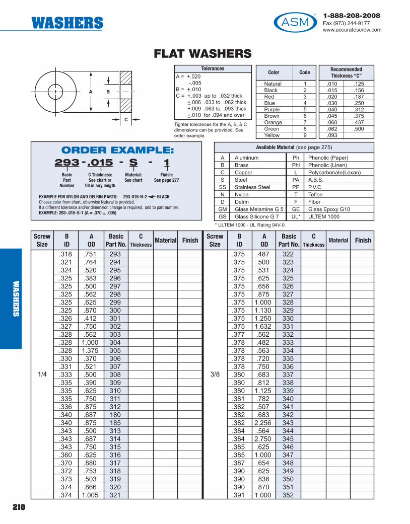
210
1-888-208-2008Fax (973) 244-9177www.accuratescrew.comWASHERS
WA
SH
ER
S
FLAT WASHERS
A Aluminum Ph Phenolic (Paper)B Brass Phl Phenolic (Linen)C Copper L Polycarbonate(Lexan)S Steel PA A.B.S.
SS Stainless Steel PP P.V.C.N Nylon T TeflonD Delrin F Fiber
GM Glass Melamine G 5 GE Glass Epoxy G10GS Glass Silicone G 7 UL* ULTEM 1000
Available Material (see page 275)
.010
.015
.020
.030
.040
.045
.060
.062
.093
.125
.156
.187
.250
.312
.375
.437
.500
RecommendedThickness “C”
Tolerances
A = +.020-.005
B = +.010C = +.003 up to .032 thick
+.006 .033 to .062 thick+.009 .063 to .093 thick+.010 for .094 and over
* ULTEM 1000 - UL Rating 94V-0
Natural 1Black 2Red 3Blue 4Purple 5Brown 6Orange 7Green 8Yellow 9
Color Code
ORDER EXAMPLE:293
BasicPart
Number
.015C Thickness:See chart or
fill in any length
SMaterial: See chart
1Finish:
See page 277
- - -
EXAMPLE FOR NYLON AND DELRIN PARTS: 293-015-N-2 BLACKChoose color from chart, otherwise Natural is provided.If a different tolerance and/or dimension change is required, add to part number.EXAMPLE: 293-.015-S-1 (A = .370 + .005)
Tighter tolerances for the A, B, & Cdimensions can be provided. Seeorder example.
.318 .751 293
.321 .764 294
.324 .520 295
.325 .383 296
.325 .500 297
.325 .562 298
.325 .625 299
.325 .870 300
.326 .412 301
.327 .750 302
.328 .562 303
.328 1.000 304
.328 1.375 305
.330 .370 306
.331 .521 307
.333 .500 308
.335 .390 309
.335 .625 310
.335 .750 311
.336 .875 312
.340 .687 180
.340 .875 185
.343 .500 313
.343 .687 314
.343 .750 315
.360 .625 316
.370 .880 317
.372 .753 318
.373 .503 319
.374 .866 320
.374 1.005 321
.375 .487 322
.375 .500 323
.375 .531 324
.375 .625 325
.375 .656 326
.375 .875 327
.375 1.000 328
.375 1.130 329
.375 1.250 330
.375 1.632 331
.377 .562 332
.378 .482 333
.378 .563 334
.378 .720 335
.378 .750 336
.380 .683 337
.380 .812 338
.380 1.125 339
.381 .782 340
.382 .507 341
.382 .683 342
.382 2.256 343
.384 .564 344
.384 2.750 345
.385 .625 346
.385 1.000 347
.387 .654 348
.390 .625 349
.390 .836 350
.390 .870 351
.391 1.000 352
3/81/4
ScrewSize
BID
AOD
BasicPart No.
CThickness
Material FinishScrewSize
BID
AOD
BasicPart No.
CThickness
Material Finish
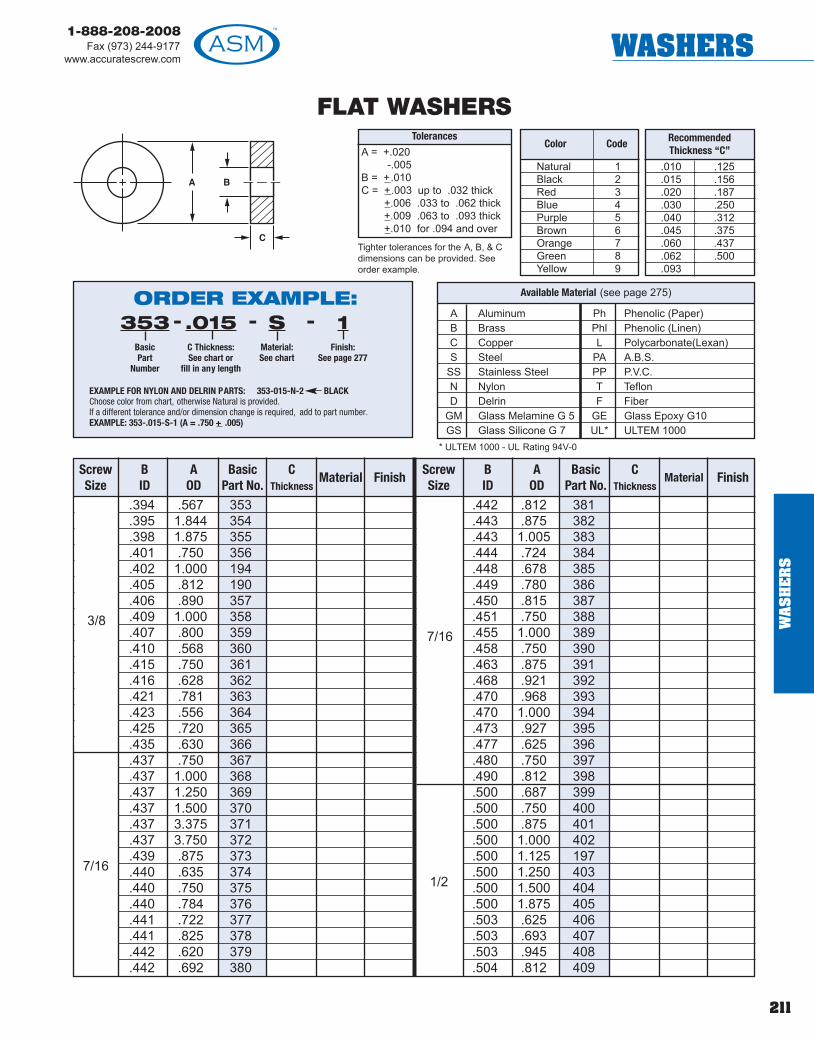
211
1-888-208-2008Fax (973) 244-9177
www.accuratescrew.com WASHERS
FLAT WASHERS
A Aluminum Ph Phenolic (Paper)B Brass Phl Phenolic (Linen)C Copper L Polycarbonate(Lexan)S Steel PA A.B.S.
SS Stainless Steel PP P.V.C.N Nylon T TeflonD Delrin F Fiber
GM Glass Melamine G 5 GE Glass Epoxy G10GS Glass Silicone G 7 UL* ULTEM 1000
Available Material (see page 275)
.010
.015
.020
.030
.040
.045
.060
.062
.093
.125
.156
.187
.250
.312
.375
.437
.500
RecommendedThickness “C”
Tolerances
A = +.020-.005
B = +.010C = +.003 up to .032 thick
+.006 .033 to .062 thick+.009 .063 to .093 thick+.010 for .094 and over
* ULTEM 1000 - UL Rating 94V-0
Natural 1Black 2Red 3Blue 4Purple 5Brown 6Orange 7Green 8Yellow 9
Color Code
ORDER EXAMPLE:353
BasicPart
Number
.015C Thickness:See chart or
fill in any length
SMaterial: See chart
1Finish:
See page 277
- - -
EXAMPLE FOR NYLON AND DELRIN PARTS: 353-015-N-2 BLACKChoose color from chart, otherwise Natural is provided.If a different tolerance and/or dimension change is required, add to part number.EXAMPLE: 353-.015-S-1 (A = .750 + .005)
Tighter tolerances for the A, B, & Cdimensions can be provided. Seeorder example.
.394 .567 353
.395 1.844 354
.398 1.875 355
.401 .750 356
.402 1.000 194
.405 .812 190
.406 .890 357
.409 1.000 358
.407 .800 359
.410 .568 360
.415 .750 361
.416 .628 362
.421 .781 363
.423 .556 364
.425 .720 365
.435 .630 366
.437 .750 367
.437 1.000 368
.437 1.250 369
.437 1.500 370
.437 3.375 371
.437 3.750 372
.439 .875 373
.440 .635 374
.440 .750 375
.440 .784 376
.441 .722 377
.441 .825 378
.442 .620 379
.442 .692 380
.442 .812 381
.443 .875 382
.443 1.005 383
.444 .724 384
.448 .678 385
.449 .780 386
.450 .815 387
.451 .750 388
.455 1.000 389
.458 .750 390
.463 .875 391
.468 .921 392
.470 .968 393
.470 1.000 394
.473 .927 395
.477 .625 396
.480 .750 397
.490 .812 398
.500 .687 399
.500 .750 400
.500 .875 401
.500 1.000 402
.500 1.125 197
.500 1.250 403
.500 1.500 404
.500 1.875 405
.503 .625 406
.503 .693 407
.503 .945 408
.504 .812 409
1/27/16
ScrewSize
BID
AOD
BasicPart No.
CThickness
Material FinishScrewSize
BID
AOD
BasicPart No.
CThickness
Material Finish
3/87/16
WA
SH
ER
S

212
1-888-208-2008Fax (973) 244-9177www.accuratescrew.comWASHERS
WA
SH
ER
S
FLAT WASHERS
A Aluminum Ph Phenolic (Paper)B Brass Phl Phenolic (Linen)C Copper L Polycarbonate(Lexan)S Steel PA A.B.S.
SS Stainless Steel PP P.V.C.N Nylon T TeflonD Delrin F Fiber
GM Glass Melamine G 5 GE Glass Epoxy G10GS Glass Silicone G 7 UL* ULTEM 1000
Available Material (see page 275)
.010
.015
.020
.030
.040
.045
.060
.062
.093
.125
.156
.187
.250
.312
.375
.437
.500
RecommendedThickness “C”
Tolerances
A = +.020-.005
B = +.010C = +.003 up to .032 thick
+.006 .033 to .062 thick+.009 .063 to .093 thick+.010 for .094 and over
* ULTEM 1000 - UL Rating 94V-0
Natural 1Black 2Red 3Blue 4Purple 5Brown 6Orange 7Green 8Yellow 9
Color Code
ORDER EXAMPLE:410
BasicPart
Number
.015C Thickness:See chart or
fill in any length
SMaterial: See chart
1Finish:
See page 277
- - -
EXAMPLE FOR NYLON AND DELRIN PARTS: 410-015-N-2 BLACKChoose color from chart, otherwise Natural is provided.If a different tolerance and/or dimension change is required, add to part number.EXAMPLE: 410-.015-S-1 (A = .750 + .005)
Tighter tolerances for the A, B, & Cdimensions can be provided. Seeorder example.
.505 .661 410
.505 .750 411
.505 .812 412
.505 .875 413
.505 1.000 414
.505 1.250 415
.506 .620 416
.510 .570 417
.510 .740 418
.510 .990 419
.513 .718 420
.515 .660 421
.515 .750 422
.515 .812 423
.515 .875 424
.515 2.000 425
.516 .656 426
.518 .635 427
.520 1.063 428
.520 1.187 429
.526 1.000 430
.528 .940 431
.530 .750 432
.531 1.000 195
.531 1.062 433
.535 .720 434
.535 1.000 435
.535 1.281 436
.536 1.062 437
.538 1.385 438
.540 .750 439
.541 .721 440
.541 .843 441
.545 .875 442
.547 .620 443
.550 .875 444
.560 .810 445
.560 1.380 446
.562 .688 447
.562 .750 448
.562 .875 449
.562 1.000 450
.562 1.250 199
.562 1.375 451
.567 1.380 452
.570 .886 453
.572 .755 454
.573 .985 455
.574 .748 456
.574 .984 457
.578 1.062 458
.578 2.188 459
.580 .750 460
.588 1.125 461
.594 1.188 462
.599 1.474 463
.600 .812 464
.600 .875 465
.609 1.474 466
.625 .750 467
1/21/2
ScrewSize
BID
AOD
BasicPart No.
CThickness
Material FinishScrewSize
BID
AOD
BasicPart No.
CThickness
Material Finish
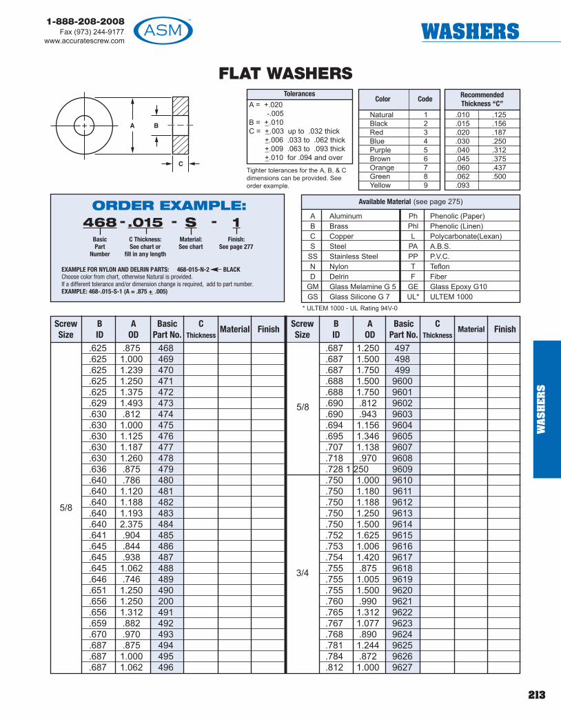
213
1-888-208-2008Fax (973) 244-9177
www.accuratescrew.com WASHERS
FLAT WASHERS
A Aluminum Ph Phenolic (Paper)B Brass Phl Phenolic (Linen)C Copper L Polycarbonate(Lexan)S Steel PA A.B.S.
SS Stainless Steel PP P.V.C.N Nylon T TeflonD Delrin F Fiber
GM Glass Melamine G 5 GE Glass Epoxy G10GS Glass Silicone G 7 UL* ULTEM 1000
Available Material (see page 275)
.010
.015
.020
.030
.040
.045
.060
.062
.093
.125
.156
.187
.250
.312
.375
.437
.500
RecommendedThickness “C”
Tolerances
A = +.020-.005
B = +.010C = +.003 up to .032 thick
+.006 .033 to .062 thick+.009 .063 to .093 thick+.010 for .094 and over
* ULTEM 1000 - UL Rating 94V-0
Natural 1Black 2Red 3Blue 4Purple 5Brown 6Orange 7Green 8Yellow 9
Color Code
ORDER EXAMPLE:468
BasicPart
Number
.015C Thickness:See chart or
fill in any length
SMaterial: See chart
1Finish:
See page 277
- - -
EXAMPLE FOR NYLON AND DELRIN PARTS: 468-015-N-2 BLACKChoose color from chart, otherwise Natural is provided.If a different tolerance and/or dimension change is required, add to part number.EXAMPLE: 468-.015-S-1 (A = .875 + .005)
Tighter tolerances for the A, B, & Cdimensions can be provided. Seeorder example.
.625 .875 468
.625 1.000 469
.625 1.239 470
.625 1.250 471
.625 1.375 472
.629 1.493 473
.630 .812 474
.630 1.000 475
.630 1.125 476
.630 1.187 477
.630 1.260 478
.636 .875 479
.640 .786 480
.640 1.120 481
.640 1.188 482
.640 1.193 483
.640 2.375 484
.641 .904 485
.645 .844 486
.645 .938 487
.645 1.062 488
.646 .746 489
.651 1.250 490
.656 1.250 200
.656 1.312 491
.659 .882 492
.670 .970 493
.687 .875 494
.687 1.000 495
.687 1.062 496
.687 1.250 497
.687 1.500 498
.687 1.750 499
.688 1.500 9600
.688 1.750 9601
.690 .812 9602
.690 .943 9603
.694 1.156 9604
.695 1.346 9605
.707 1.138 9607
.718 .970 9608
.728 1 250 9609
.750 1.000 9610
.750 1.180 9611
.750 1.188 9612
.750 1.250 9613
.750 1.500 9614
.752 1.625 9615
.753 1.006 9616
.754 1.420 9617
.755 .875 9618
.755 1.005 9619
.755 1.500 9620
.760 .990 9621
.765 1.312 9622
.767 1.077 9623
.768 .890 9624
.781 1.244 9625
.784 .872 9626
.812 1.000 9627
5/8
ScrewSize
BID
AOD
BasicPart No.
CThickness
Material FinishScrewSize
BID
AOD
BasicPart No.
CThickness
Material Finish
3/4
5/8
WA
SH
ER
S
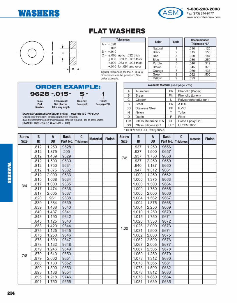
214
1-888-208-2008Fax (973) 244-9177www.accuratescrew.comWASHERS
WA
SH
ER
S
FLAT WASHERS
A Aluminum Ph Phenolic (Paper)B Brass Phl Phenolic (Linen)C Copper L Polycarbonate(Lexan)S Steel PA A.B.S.
SS Stainless Steel PP P.V.C.N Nylon T TeflonD Delrin F Fiber
GM Glass Melamine G 5 GE Glass Epoxy G10GS Glass Silicone G 7 UL* ULTEM 1000
Available Material (see page 275)
.010
.015
.020
.030
.040
.045
.060
.062
.093
.125
.156
.187
.250
.312
.375
.437
.500
RecommendedThickness “C”
Tolerances
A = +.020-.005
B = +.010C = +.003 up to .032 thick
+.006 .033 to .062 thick+.009 .063 to .093 thick+.010 for .094 and over
* ULTEM 1000 - UL Rating 94V-0
Natural 1Black 2Red 3Blue 4Purple 5Brown 6Orange 7Green 8Yellow 9
Color Code
ORDER EXAMPLE:9628
BasicPart
Number
.015C Thickness:See chart or
fill in any length
SMaterial: See chart
1Finish:
See page 277
- - -
EXAMPLE FOR NYLON AND DELRIN PARTS: 9628-015-N-2 BLACKChoose color from chart, otherwise Natural is provided.If a different tolerance and/or dimension change is required, add to part number.EXAMPLE: 9628-.015-S-1 (A = 1.420 + .005)
Tighter tolerances for the A, B, & Cdimensions can be provided. Seeorder example.
.812 1.250 9628
.812 1.375 205
.812 1.469 9629
.812 1.500 9630
.812 1.750 9631
.812 1.875 9632
.812 2.000 9633
.815 1.068 9634
.817 1.000 9635
.817 1.474 9636
.817 2.005 9637
.820 .961 9638
.839 1.384 9639
.839 1.438 9640
.840 1.437 9641
.843 1.190 9642
.845 1.125 9643
.853 1.420 9644
.875 1.125 9645
.875 1.250 9646
.875 1.500 9647
.878 1.132 9648
.879 1.246 9649
.879 1.640 9650
.879 2.000 9651
.880 1.130 9652
.890 1.500 9653
.893 1.136 9654
.895 1.218 9746
.901 1.750 9655
.937 1.250 9656
.937 1.500 9657
.937 1.750 9658
.937 2.250 9659
.940 1.187 9660
.947 1.312 96611.000 1.250 96621.000 1.375 96631.000 1.500 96641.000 1.750 96651.000 2.000 96661.004 1.562 96671.004 1.875 96681.004 2.250 96691.010 1.250 96701.015 1.750 96711.020 1.330 96721.026 2.000 96731.031 1.500 96741.062 2.000 96751.062 2.500 96761.067 2.005 96771.067 2.505 96781.069 1.250 96791.073 1.312 96801.073 1.365 96811.073 1.500 96821.078 1.812 96831.078 1.880 96841.081 1.639 9685
1.00
3/4
ScrewSize
BID
AOD
BasicPart No.
CThickness
Material FinishScrewSize
BID
AOD
BasicPart No.
CThickness
Material Finish
7/8
7/8

215
1-888-208-2008Fax (973) 244-9177
www.accuratescrew.com WASHERS
FLAT WASHERS
A Aluminum Ph Phenolic (Paper)B Brass Phl Phenolic (Linen)C Copper L Polycarbonate(Lexan)S Steel PA A.B.S.
SS Stainless Steel PP P.V.C.N Nylon T TeflonD Delrin F Fiber
GM Glass Melamine G 5 GE Glass Epoxy G10GS Glass Silicone G 7 UL* ULTEM 1000
Available Material (see page 275)
.010
.015
.020
.030
.040
.045
.060
.062
.093
.125
.156
.187
.250
.312
.375
.437
.500
RecommendedThickness “C”
Tolerances
A = +.020-.005
B = +.010C = +.003 up to .032 thick
+.006 .033 to .062 thick+.009 .063 to .093 thick+.010 for .094 and over
* ULTEM 1000 - UL Rating 94V-0
Natural 1Black 2Red 3Blue 4Purple 5Brown 6Orange 7Green 8Yellow 9
Color Code
ORDER EXAMPLE:9690
BasicPart
Number
.015C Thickness:See chart or
fill in any length
SMaterial: See chart
1Finish:
See page 277
- - -
EXAMPLE FOR NYLON AND DELRIN PARTS: 9690-015-N-2 BLACKChoose color from chart, otherwise Natural is provided.If a different tolerance and/or dimension change is required, add to part number.EXAMPLE: 9690-.015-S-1 (A = 1.260 + .005)
Tighter tolerances for the A, B, & Cdimensions can be provided. Seeorder example.
1.129 2.095 96901.129 2.500 96911.135 1.370 96921.137 1.625 96931.165 1.562 96941.187 2.500 96951.187 2.750 96961.188 1.732 96971.195 1.436 96981.198 1.750 96991.250 2.750 97001.252 2.000 97011.254 2.350 97021.258 1.507 97031.260 1.812 97041.260 1.875 97051.265 2.005 97061.279 1.611 97071.281 1.750 97081.312 2.750 97091.312 3.000 97101.323 1.615 97111.323 1.875 97121.324 1.575 97131.328 2.062 97141.328 2.067 97151.347 1.888 97161.379 2.585 9717
1.421 1.812 97181.437 3.250 97191.443 2.000 97201.504 2.820 97211.505 2.000 97221.506 1.998 97231.510 2.062 97241.525 2.150 97251.562 3.250 97261.562 3.500 97271.572 2.125 97281.635 1.865 97291.635 2.188 97301.640 2.375 97311.699 2.250 97321.790 2.440 97331.827 2.375 97341.863 2.645 97351.885 2.115 97361.890 2.375 97371.890 2.625 97381.947 2.500 97391.950 3.000 97402.073 2.625 97412.198 2.750 37422.265 3.000 97432.515 3.250 9744
2.00
1.00
ScrewSize
BID
AOD
BasicPart No.
CThickness
Material FinishScrewSize
BID
AOD
BasicPart No.
CThickness
Material Finish
1.25
1.25
1.50
WA
SH
ER
S

216
1-888-208-2008Fax (973) 244-9177www.accuratescrew.comWASHERS
NEOPRENE FLAT WASHERSDurameter - Medium #60
.015 - .031 +.005.047 +.006.062 +.008.093 +.012.125 +.015
Thicknessesand Tolerances
Available
Basic Part Number Screw Size
Inside Dia+.010
Outside Dia+.010
9800 0 .070 .1999801 0 .070 .3129802 0 .070 .2429808 1 .086 .2429810 1 .086 .3299811 1 .086 .3759812 2 .093 .2359816 2 .093 .3909820 3 .109 .2359822 3 .109 .2839823 3 .108 .5009824 3 .109 .3909828 4 .120 .3809830 4 .120 .5299832 4 .125 .2509836 6 .150 .3809838 6 .150 .4009840 6 .150 .4789842 6 .150 .6449844 6 .156 .3759849 6 .156 .7509850 6 .156 2.0009851 6 .156 1.009854 8 .171 .3809856 8 .171 .4309862 8 .187 .3129863 8 .187 .5009864 10 .203 .4439866 10 .203 .465
NOTES: Tensile Strength, PSI 1500Hardness, 50-70 SDHResistance to Continuous Heat, °F 175
ORDER EXAMPLE:9800
BasicPart Number
.016Thickness
-
WA
SH
ER
S
! TECHTIPTolerances onfractions are largerthan the toleranceson decimals.

217
1-888-208-2008Fax (973) 244-9177
www.accuratescrew.com WASHERS
9871 .203 1.0009872 .265 .5059877 .265 .6259878 .265 .7459882 .328 .5679884 .328 .6879886 .328 .8129887 .328 1.0009892 .390 .7459893 .390 .7819894 .390 .8659898 .453 .75598100 .453 .88098102 .515 .75098103 .453 1.0098104 .515 .88098106 .515 1.00098110 .640 .87598112 .640 1.00098113 .640 1.25098117 .687 1.00098118 .765 1.00098120 .765 1.18798124 .890 1.25098128 1.015 1.25098130 1.015 1.50098133 1.015 2.00
10
NEOPRENE FLAT WASHERSDurameter - Medium #60
NOTES: Tensile Strength, PSI 1500Hardness, 50-70 SDHResistance to Continuous Heat, °F 175
.015 - .031 +.005.047 +.006.062 +.008.093 +.012.125 +.015
Thicknessesand Tolerances
Available
Basic Part Number Screw Size
Inside Dia+.010
Outside Dia+.010
ORDER EXAMPLE:9871
BasicPart Number
.016Thickness
-
WA
SH
ER
S

218
1-888-208-2008Fax (973) 244-9177www.accuratescrew.comWASHERS
WA
SH
ER
S
SHOULDER WASHERS
.046 .140 .187 15000
.051 .090 .127 1500200
.053 .125 .250 15004
.055 .125 .344 15006
.062 .090 .156 15008
.062 .156 .250 150100
.063 .125 .187 15012
.070 .105 .140 15014
.078 .150 .215 150161
.083 .123 .240 15018
.090 .122 .187 15020
.090 .131 .187 15022
.090 .187 .313 15024
.092 .151 .219 15026
.093 .115 .140 15028
.093 .122 .250 15030
.093 .125 .187 15032
.093 .125 .234 15034
.093 .140 .250 15036
.093 .152 .312 15038
.093 .154 .250 150402
.094 .137 .250 15042
.095 .155 .265 15044
.096 .180 .312 15046
.097 .125 .187 15048
.098 .136 .312 15050
.098 .140 .250 15052
.098 .170 .218 15054
.098 .190 .250 15056
.099 .128 .312 15058
.100 .187 .250 16060
.100 .187 .375 15062
.103 .160 .250 15064
.103 .192 .316 150663 .106 .165 .312 15068
.106 .170 .250 15070
.107 .152 .224 15072
A Aluminum Ph Phenolic (Paper)B Brass Phl Phenolic (Linen)C Copper L Polycarbonate(Lexan)S Steel PA A.B.S.
SS Stainless Steel PP P.V.C.N Nylon T TeflonD Delrin F F ber
GE Glass Epoxy UL ULTEM 1000 -G10 UL Rating 94V-O
Available Material (see page 275)
Natural 1Black 2Red 3Blue 4Purple 5
Brown 6Orange 7Green 8Yellow 9
Color Code Color Code
ORDER EXAMPLE:15000
BasicPart
Number
.060Shoulder Length E:
Fill in length
.030Shank Length D:
Fill in length
SMaterial:See chart
--- 1Finish:
See page277
-
EXAMPLE FOR NYLON AND DELRIN PARTS: 15000-.060-.030-N-2 BLACKChoose color from chart, otherwise Natural is provided.If a different tolerance and/or dimension change is required, add to part number.EXAMPLE: 15000-.060-.030-S-1 (A = .078)Internal threaded Shoulder Washers are available. Add desired thread to part number (see pa ge 281).EXAMPLE: 15010-.050-.050-B-1 (A = 2-56)
ScrewSize
A± .005
B± .010
C± .010
Basic Part Number
EShoulder Length
± .005
DShank Length
± .005Material Finish
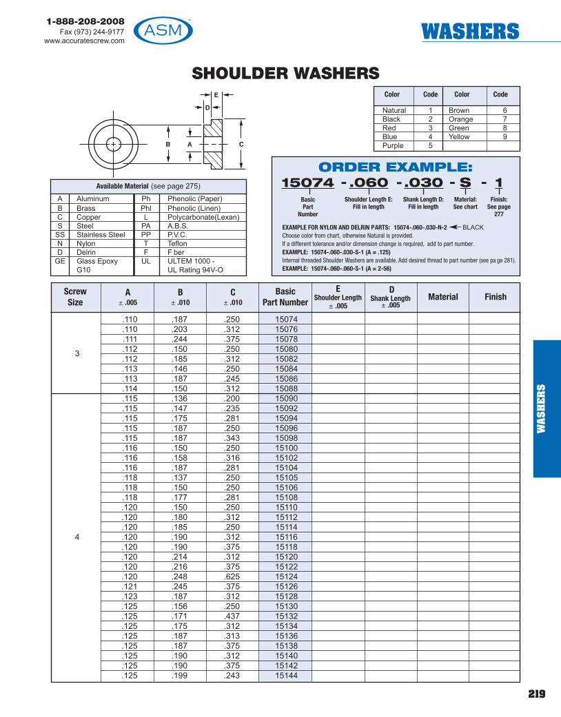
219
1-888-208-2008Fax (973) 244-9177
www.accuratescrew.com WASHERS
SHOULDER WASHERS
.110 .187 .250 15074
.110 .203 .312 15076.111 .244 .375 15078.112 .150 .250 150803.112 .185 .312 15082.113 .146 .250 15084.113 .187 .245 15086.114 .150 .312 15088.115 .136 .200 15090.115 .147 .235 15092.115 .175 .281 15094.115 .187 .250 15096.115 .187 .343 15098.116 .150 .250 15100.116 .158 .316 15102.116 .187 .281 15104.118 .137 .250 15105.118 .150 .250 15106.118 .177 .281 15108.120 .150 .250 15110.120 .180 .312 15112.120 .185 .250 15114
4 .120 .190 .312 15116.120 .190 .375 15118.120 .214 .312 15120.120 .216 .375 15122.120 .248 .625 15124.121 .245 .375 15126.123 .187 .312 15128.125 .156 .250 15130.125 .171 .437 15132.125 .175 .312 15134.125 .187 .313 15136.125 .187 .375 15138.125 .190 .312 15140.125 .190 .375 15142.125 .199 .243 15144
A Aluminum Ph Phenolic (Paper)B Brass Phl Phenolic (Linen)C Copper L Polycarbonate(Lexan)S Steel PA A.B.S.
SS Stainless Steel PP P.V.C.N Nylon T TeflonD Delrin F F ber
GE Glass Epoxy UL ULTEM 1000 -G10 UL Rating 94V-O
Available Material (see page 275)
Natural 1Black 2Red 3Blue 4Purple 5
Brown 6Orange 7Green 8Yellow 9
Color Code Color Code
ORDER EXAMPLE:15074
BasicPart
Number
.060Shoulder Length E:
Fill in length
.030Shank Length D:
Fill in length
SMaterial:See chart
--- 1Finish:
See page277
-
EXAMPLE FOR NYLON AND DELRIN PARTS: 15074-.060-.030-N-2 BLACKChoose color from chart, otherwise Natural is provided.If a different tolerance and/or dimension change is required, add to part number.EXAMPLE: 15074-.060-.030-S-1 (A = .125)Internal threaded Shoulder Washers are available. Add desired thread to part number (see pa ge 281).EXAMPLE: 15074-.060-.060-S-1 (A = 2-56)
ScrewSize
A± .005
B± .010
C± .010
Basic Part Number
EShoulder Length
± .005
DShank Length
± .005Material Finish
WA
SH
ER
S

220
1-888-208-2008Fax (973) 244-9177www.accuratescrew.comWASHERS
WA
SH
ER
S
SHOULDER WASHERS
.125 .203 .421 15146
.125 .218 .312 15148
.125 .218 .343 15150
.125 .241 .312 151524 .125 .250 .375 15154
.125 .312 .375 15156
.125 .312 .625 15158
.126 .197 .312 15160
.127 .155 .265 15162
.128 .150 .234 15164
.128 .185 .312 15166
.128 .185 .375 15168
.128 .187 .312 15170
.128 .193 .281 15172
.128 .203 .375 15174
.128 .218 .312 15176
.128 .250 .375 15178
.128 .265 .320 15180
.129 .185 .345 15182
.129 .185 .378 15184
.129 .212 .437 15186
.130 .177 .281 15188
.130 .185 .335 151905
.130 .187 .343 15192
.130 .192 .437 15194
.130 .208 .312 15196
.130 .250 .375 15198
.133 .219 .343 15200
.133 .240 .355 15202
.133 .187 .312 15204
.135 .187 .328 15206
.135 .187 .437 15208
.136 .185 .312 15210
.136 .187 .250 15212
.136 .187 .312 15214
.136 .221 .312 15216
.136 .245 .375 15218
A Aluminum Ph Phenolic (Paper)B Brass Phl Phenolic (Linen)C Copper L Polycarbonate(Lexan)S Steel PA A.B.S.
SS Stainless Steel PP P.V.C.N Nylon T TeflonD Delrin F F ber
GE Glass Epoxy UL ULTEM 1000 -G10 UL Rating 94V-O
Available Material (see page 275)
Natural 1Black 2Red 3Blue 4Purple 5
Brown 6Orange 7Green 8Yellow 9
Color Code Color Code
ORDER EXAMPLE:15146
BasicPart
Number
.060Shoulder Length E:
Fill in length
.030Shank Length D:
Fill in length
SMaterial:See chart
--- 1Finish:
See page277
-
EXAMPLE FOR NYLON AND DELRIN PARTS: 15146-.060-.030-N-2 BLACKChoose color from chart, otherwise Natural is provided.If a different tolerance and/or dimension change is required, add to part number.EXAMPLE: 15146-.060-.030-S-1 (A = .136)Internal threaded Shoulder Washers are available. Add desired thread to part number (see pa ge 281).EXAMPLE: 15146-.060-.060-B-1 (A = 2-56)
ScrewSize
A± .005
B± .010
C± .010
Basic Part Number
EShoulder Length
± .005
DShank Length
± .005Material Finish

221
1-888-208-2008Fax (973) 244-9177
www.accuratescrew.com WASHERS
SHOULDER WASHERS
.136 .437 .562 152205 .138 .190 .281 15222
.139 .183 .312 15224
.140 .170 .290 15226
.140 .185 .312 15228
.140 .185 .378 15230
.140 .187 .234 15232
.140 .187 .312 15234
.140 .187 .328 15236
.140 .210 .312 15238
.140 .210 .375 15240
.140 .212 .437 15242
.140 .224 .343 15244
.140 .234 .500 15246
.140 .237 .375 15248
.141 .182 .320 15250
.141 .187 .250 15252
.141 .187 .312 15254
.141 .250 .375 15256
.144 .187 .313 152586
.144 .213 .310 15260
.144 .250 .437 15262
.144 .281 .437 15264
.144 .312 .437 15266
.146 .248 .375 15268
.147 .172 .312 15270
.147 .187 .375 15272
.147 .255 .375 15274
.147 .360 .500 15276
.150 .203 .247 15278
.150 .250 .355 15280
.152 .199 .378 15282
.155 .245 .360 15284
.156 .250 .375 15286
.156 .250 .437 15288
.156 .250 .500 15290
.156 .312 .500 15292
A Aluminum Ph Phenolic (Paper)B Brass Phl Phenolic (Linen)C Copper L Polycarbonate(Lexan)S Steel PA A.B.S.
SS Stainless Steel PP P.V.C.N Nylon T TeflonD Delrin F F ber
GE Glass Epoxy UL ULTEM 1000 -G10 UL Rating 94V-O
Available Material (see page 275)
Natural 1Black 2Red 3Blue 4Purple 5
Brown 6Orange 7Green 8Yellow 9
Color Code Color Code
ORDER EXAMPLE:15220
BasicPart
Number
.060Shoulder Length E:
Fill in length
.030Shank Length D:
Fill in length
SMaterial:See chart
--- 1Finish:
See page277
-
EXAMPLE FOR NYLON AND DELRIN PARTS: 15220-.060-.030-N-2 BLACKChoose color from chart, otherwise Natural is provided.If a different tolerance and/or dimension change is required, add to part number.EXAMPLE: 15220-.060-.030-S-1 (A = .150)Internal threaded Shoulder Washers are available. Add desired thread to part number (see pa ge 281).EXAMPLE: 15220-.060-.060-SS-1 (A = 4-40)
ScrewSize
A± .005
B± .010
C± .010
Basic Part Number
EShoulder Length
± .005
DShank Length
± .005Material Finish
WA
SH
ER
S

222
1-888-208-2008Fax (973) 244-9177www.accuratescrew.comWASHERS
WA
SH
ER
S
SHOULDER WASHERS
.160 .220 .343 15294
.160 .250 .375 15296
.161 .275 .433 15298
.162 .218 .359 15300
.162 .250 .625 15302
.163 .213 .437 153046
.163 .229 .312 15306
.163 .430 .625 15308
.165 .281 .625 15310
.165 .312 .437 15312
.166 .268 .500 15314
.168 .250 .375 15316
.168 .250 .437 15318
.169 .215 .375 15320
.169 .218 .312 15322
.169 .236 .384 15324
.169 .245 .437 15326
.169 .245 .440 15328
.169 .250 .380 15330
.169 .278 .562 15332
.170 .205 .344 15334
.170 .234 .375 15336
.170 .245 .390 15338
.170 .250 .312 153408 .170 .263 .437 15342
.170 .312 .562 15344
.171 .250 .375 15346
.171 .250 .500 15348
.173 .300 .468 15350
.173 .370 .500 15352
.173 .437 .562 15354
.174 .218 .375 15356
.174 .250 .375 15358
.175 .260 .437 15360
.176 .213 .437 15362
.178 .312 .500 15364
.185 .255 .365 15366
A Aluminum Ph Phenolic (Paper)B Brass Phl Phenolic (Linen)C Copper L Polycarbonate(Lexan)S Steel PA A.B.S.
SS Stainless Steel PP P.V.C.N Nylon T TeflonD Delrin F F ber
GE Glass Epoxy UL ULTEM 1000 -G10 UL Rating 94V-O
Available Material (see page 275)
Natural 1Black 2Red 3Blue 4Purple 5
Brown 6Orange 7Green 8Yellow 9
Color Code Color Code
ORDER EXAMPLE:15294
BasicPart
Number
.060Shoulder Length E:
Fill in length
.030Shank Length D:
Fill in length
SMaterial:See chart
--- 1Finish:
See page277
-
EXAMPLE FOR NYLON AND DELRIN PARTS: 15294-.060-.030-N-2 BLACKChoose color from chart, otherwise Natural is provided.If a different tolerance and/or dimension change is required, add to part number.EXAMPLE: 15294-.060-.030-S-1 (A = .175)Internal threaded Shoulder Washers are available. Add desired thread to part number (see pa ge 281).EXAMPLE: 15294-.060-.040-SS-1 (A = 4-40)
ScrewSize
A± .005
B± .010
C± .010
Basic Part Number
EShoulder Length
± .005
DShank Length
± .005Material Finish

223
1-888-208-2008Fax (973) 244-9177
www.accuratescrew.com WASHERS
SHOULDER WASHERS
.187 .250 .312 15368
.187 .250 .375 15370
.187 .250 .500 15372
.187 .265 .375 15374
.187 .281 .437 15376
.187 .281 1.500 15378
.187 .312 .562 15380
.187 .372 .437 153828 .188 .280 .500 15384
.190 .265 .500 15386
.190 .312 .500 15388
.191 .275 .406 15390
.192 .309 .625 15392
.193 .246 .500 15394
.193 .257 .375 15396
.193 .312 .440 15398
.193 .368 .500 15400
.194 .233 .281 15402
.194 .277 .531 15404
.194 .308 .375 15406
.194 .495 .750 15408
.195 .240 .375 15410
.195 .310 .437 15412
.195 .310 .625 15414
.196 .250 .312 15416
.196 .250 .380 15418
.196 .300 .500 1542010
.196 .300 .581 15422
.196 .308 .375 15424
.196 .312 .625 15426
.196 .375 .625 15428
.198 .247 .750 15430
.199 .248 .500 15432
.199 .300 .468 15434
.199 .341 .750 15436
.200 .240 .500 15438
.200 .245 .530 15440
A Aluminum Ph Phenolic (Paper)B Brass Phl Phenolic (Linen)C Copper L Polycarbonate(Lexan)S Steel PA A.B.S.
SS Stainless Steel PP P.V.C.N Nylon T TeflonD Delrin F F ber
GE Glass Epoxy UL ULTEM 1000 -G10 UL Rating 94V-O
Available Material (see page 275)
Natural 1Black 2Red 3Blue 4Purple 5
Brown 6Orange 7Green 8Yellow 9
Color Code Color Code
ORDER EXAMPLE:15368
BasicPart
Number
.060Shoulder Length E:
Fill in length
.030Shank Length D:
Fill in length
SMaterial:See chart
--- 1Finish:
See page277
-
EXAMPLE FOR NYLON AND DELRIN PARTS: 15368-.060-.030-N-2 BLACKChoose color from chart, otherwise Natural is provided.If a different tolerance and/or dimension change is required, add to part number.EXAMPLE: 15368-.060-.030-S-1 (A = .199)Internal threaded Shoulder Washers are available. Add desired thread to part number (see pa ge 281).EXAMPLE: 15368-.040-.040-B-1 (A = 4-40)
ScrewSize
A± .005
B± .010
C± .010
Basic Part Number
EShoulder Length
± .005
DShank Length
± .005Material Finish
WA
SH
ER
S

224
1-888-208-2008Fax (973) 244-9177www.accuratescrew.comWASHERS
WA
SH
ER
S
SHOULDER WASHERS
.200 .245 .531 15442
.200 .250 .437 15444
.200 .252 .375 15446
.200 .260 .399 15448
.200 .280 .437 15450
.200 .303 .390 15452
.200 .304 .375 15454
.200 .430 .625 15456
.201 .358 .750 15458
.201 .358 1.000 15460
.201 .358 1.375 15462
.203 .250 .500 15464
.203 .296 .468 15466
.203 .312 .437 1546810
.203 .312 .750 15470
.203 .313 .390 15472
.204 .270 .500 15474
.205 .324 .590 15476
.205 .500 1.375 15478
.206 .358 1.000 15480
.208 .275 .380 15482
.210 .245 .437 15484
.210 .281 .437 15486
.212 .272 .343 15488
.215 .380 .635 15490
.218 .310 .500 15492
.218 .375 .500 15494
.218 .375 .625 15496
.220 .281 .375 15498
.223 .312 .500 1550012
.234 .365 .500 15502
.235 .335 .500 15504
.250 .312 .375 15506
.250 .312 .750 150081/4 .250 .343 .437 15510
.250 .343 .625 15512
.250 .375 .500 15514
A Aluminum Ph Phenolic (Paper)B Brass Phl Phenolic (Linen)C Copper L Polycarbonate(Lexan)S Steel PA A.B.S.
SS Stainless Steel PP P.V.C.N Nylon T TeflonD Delrin F F ber
GE Glass Epoxy UL ULTEM 1000 -G10 UL Rating 94V-O
Available Material (see page 275)
Natural 1Black 2Red 3Blue 4Purple 5
Brown 6Orange 7Green 8Yellow 9
Color Code Color Code
ORDER EXAMPLE:15442
BasicPart
Number
.060Shoulder Length E:
Fill in length
.030Shank Length D:
Fill in length
SMaterial:See chart
--- 1Finish:
See page277
-
EXAMPLE FOR NYLON AND DELRIN PARTS: 15442-.060-.030-N-2 BLACKChoose color from chart, otherwise Natural is provided.If a different tolerance and/or dimension change is required, add to part number.EXAMPLE: 15442-.060-.030-S-1 (A = .215)Internal threaded Shoulder Washers are available. Add desired thread to part number (see pa ge 281).EXAMPLE: 15442-.060-.060-S-1 (A = 4-40)
ScrewSize
A± .005
B± .010
C± .010
Basic Part Number
EShoulder Length
± .005
DShank Length
± .005Material Finish

225
1-888-208-2008Fax (973) 244-9177
www.accuratescrew.com WASHERS
SHOULDER WASHERS
.250 .437 .625 15516
.252 .372 .500 15518
.253 .307 .438 15520
.253 .308 .500 15522
.253 .312 .437 15524
.255 .275 .437 15526
.255 .341 .500 15528
.257 .310 .750 15530
.257 .312 .560 15532
.257 .323 .420 15534
.258 .344 .500 15536
.260 .310 .437 15538
.260 .312 .500 15540
.260 .338 .515 15542
.260 .365 .500 15544
.260 .375 .500 15545
.260 .375 .625 155461/4
.260 .503 .750 15548
.265 .345 .500 15550
.265 .359 .625 15552
.265 .365 .500 15554
.265 .370 .750 15556
.265 .484 .875 15558
.268 .430 .625 15560
.280 .343 .437 15562
.281 .312 .625 15564
.281 .375 .750 15566
.281 .421 .500 15568
.281 .500 .750 15570
.281 .562 1.000 15572
.286 .349 .531 15574
.290 .387 .562 15576
.296 .339 .531 15578
.305 .437 .750 15580
.312 .432 .562 15582
.312 .437 .500 15584
.312 .500 .625 15586
A Aluminum Ph Phenolic (Paper)B Brass Phl Phenolic (Linen)C Copper L Polycarbonate(Lexan)S Steel PA A.B.S.
SS Stainless Steel PP P.V.C.N Nylon T TeflonD Delrin F F ber
GE Glass Epoxy UL ULTEM 1000 -G10 UL Rating 94V-O
Available Material (see page 275)
Natural 1Black 2Red 3Blue 4Purple 5
Brown 6Orange 7Green 8Yellow 9
Color Code Color Code
ORDER EXAMPLE:15516
BasicPart
Number
.060Shoulder Length E:
Fill in length
.030Shank Length D:
Fill in length
SMaterial:See chart
--- 1Finish:
See page277
-
EXAMPLE FOR NYLON AND DELRIN PARTS: 15516-.060-.030-N-2 BLACKChoose color from chart, otherwise Natural is provided.If a different tolerance and/or dimension change is required, add to part number.EXAMPLE: 15516-.060-.030-S-1 (A = .305)Internal threaded Shoulder Washers are available. Add desired thread to part number (see pa ge 281).EXAMPLE: 15516-.060-.030-S-1 (A = 4-40)
ScrewSize
A± .005
B± .010
C± .010
Basic Part Number
EShoulder Length
± .005
DShank Length
± .005Material Finish
WA
SH
ER
S

226
1-888-208-2008Fax (973) 244-9177www.accuratescrew.comWASHERS
WA
SH
ER
S
SHOULDER WASHERS
.321 .437 .750 15590
.323 .375 .750 15592323 .437 .562 15594.327 .355 .750 15596.330 .520 .750 15598.343 .437 .625 15600.343 .562 1.000 15602.345 .470 .625 15604.375 .500 .625 156065/16.375 .500 .687 15608.375 .500 .750 15610.375 .500 1.000 15612.375 .625 1.000 15614.377 .435 .614 15616.380 .430 .625 15618.380 .442 .625 15620.380 .500 .625 15622.380 .558 .812 15624.385 .500 .625 15626.385 .562 .687 15628.386 .443 .562 15630.386 .484 .687 15632.400 .503 .750 15634
3/8 .406 .500 .625 15636.406 .574 .625 15638.437 .496 .625 15640.437 .562 .750 15642.437 .593 .875 15644.438 .600 .750 15646.452 .562 .688 15648.463 .506 .625 15650.477 .559 .650 15652
7/16 .500 .562 .750 15654.500 .750 .1.000 15656.505 .569 .875 15658.508 .558 .890 15660
1/2 .513 .572 .796 15662
A Aluminum Ph Phenolic (Paper)B Brass Phl Phenolic (Linen)C Copper L Polycarbonate(Lexan)S Steel PA A.B.S.
SS Stainless Steel PP P.V.C.N Nylon T TeflonD Delrin F F ber
GE Glass Epoxy UL ULTEM 1000 -G10 UL Rating 94V-O
Available Material (see page 275)
Natural 1Black 2Red 3Blue 4Purple 5
Brown 6Orange 7Green 8Yellow 9
Color Code Color Code
ORDER EXAMPLE:15590
BasicPart
Number
.060Shoulder Length E:
Fill in length
.030Shank Length D:
Fill in length
SMaterial:See chart
--- 1Finish:
See page277
-
EXAMPLE FOR NYLON AND DELRIN PARTS: 15590-.060-.030-N-2 BLACKChoose color from chart, otherwise Natural is provided.If a different tolerance and/or dimension change is required, add to part number.EXAMPLE: 15590-.060-.030-S-1 (A = .125)Internal threaded Shoulder Washers are available. Add desired thread to part number (see pa ge 281).EXAMPLE: 15590-.060-.030-N-1 (A = 4-40)
ScrewSize
A± .005
B± .010
C± .010
Basic Part Number
EShoulder Length
± .005
DShank Length
± .005Material Finish
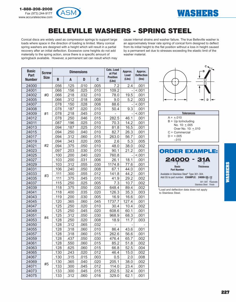
227
1-888-208-2008Fax (973) 244-9177
www.accuratescrew.com WASHERS
BELLEVILLE WASHERS - SPRING STEEL
BasicPart
Number
ScrewSize B
Dimensions
A D C
Calc. Loadat Flat
Position(Lbs)
Approx.Load(Lbs)
Approx.Deflection
(Ins)
24000 .056 .125 .010 .005 7.2 2.4 .00124001 .066 .156 .025 .010 109.2 - <.00124002 .066 .218 .032 .010 78.0 19.5 .00124005 .066 .312 .018 .008 9.0 5.2 .00324007 .078 .150 .028 .008 88.6 - <.00124008 .078 .187 .020 .010 50.4 9.3 .00124009 .078 .218 .045 .010 - - <.00124012 .078 .250 .046 .015 282.5 46.1 .00124011 .087 .196 .025 .010 70.3 14.2 .00124013 .094 .187 .025 .010 81.8 16.5 .00124015 .094 .250 .040 .010 82.7 26.3 .00124017 .094 .312 .060 .015 263.0 56.7 .00124019 .094 .343 .020 .005 2.6 5.3 .00524021 .094 .375 .050 .010 48.0 38.0 .00224023 .097 .203 .030 .010 90.1 21.2 .00124025 .100 .200 .040 .020 760.8 - <.00124027 .103 .200 .031 .006 26.1 18.1 .00124029 .103 .312 .055 .030 1174.8 77.6 .00124031 .106 .240 .050 .008 67.1 44.0 .00124033 .111 .300 .055 .012 141.8 44.2 .00124035 .111 .375 .045 .010 41.9 29.2 .00224037 .115 .250 .025 .005 7.3 10.7 .00224039 .118 .375 .050 .030 648.4 89.4 .00224041 .118 .400 .035 .020 126.3 35.3 .00324043 .119 .200 .030 .005 16.9 16.6 .00124045 .120 .365 .060 .045 1737.7 127.4 .00124047 .125 .250 .020 .010 30.4 10.4 .00224049 .125 .250 .045 .020 608.6 60.1 .00124051 .125 .312 .050 .030 968.9 68.3 .00124053 .128 .250 .020 .008 18.9 11.7 .00324050 .128 .312 .065 .032 - - -24055 .128 .318 .060 .010 86.4 43.6 .00124057 .128 .318 .060 .015 262.6 56.6 .00124059 .128 .437 .050 .030 476.4 65.7 .00224061 .128 .550 .060 .015 85.2 51.8 .00224063 .128 .625 .060 .015 66.8 52.5 .00424065 .130 .243 .020 .012 46.4 15.0 .00224067 .130 .315 .015 .003 0.5 2.0 .00824069 .130 .365 .040 .020 205.1 38.0 .00224071 .133 .300 .045 .012 114.0 23.4 .00124073 .133 .300 .045 .015 202.5 32.4 .00124075 .133 .312 .060 .016 329.0 62.1 .001
#1
#0
#2
#5
#3
#4
Conical discs are widely used as compression springs to support largeloads where space in the direction of loading is limited. Many conicalspring washers are designed with a height which will result in a partialrecovery after an initial deflection. Excessive cone heights do not addmaterially to the spring action, since there is a specific amount ofspringback available. However, a permanent set can result which may
cause internal strains and washer failure. The true Belleville washer isan approximately linear rate spring of conical form designed to deflectfrom its initial height to the flat position without a loss in height causedby a permanent set due to stresses exceeding the elastic limit of thewasher material.
TolerancesA = +.010B = Up to/including
No. 10: +.005Over No. 10: +.010
C = CommercialD = +.005
-.015
*Load and deflection data does not applyto Stainless Steel.
ORDER EXAMPLE:24000
BasicPart Number
31AThickness
-
Available in Stainless Steel* Type 301-304.Add SS to part number. EXAMPLE: 24000-SS-12
301-304Stainless Steel
PassivateFinish
WA
SH
ER
S
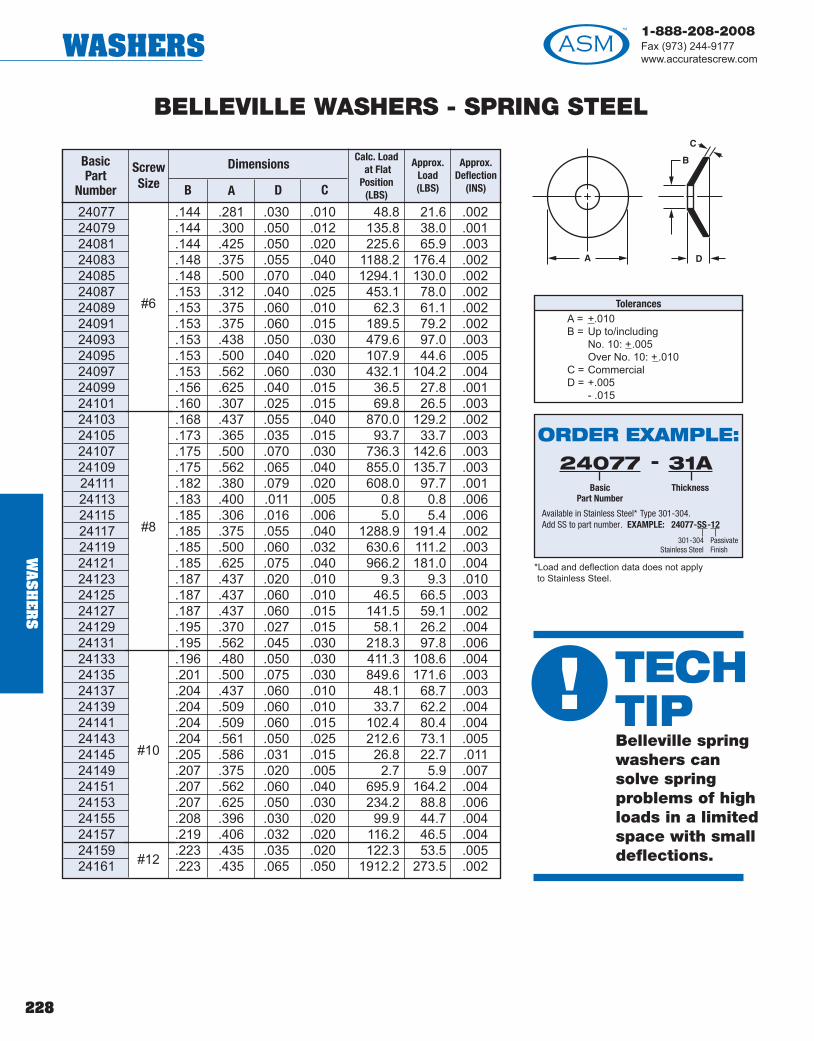
228
1-888-208-2008Fax (973) 244-9177www.accuratescrew.comWASHERS
24077 .144 .281 .030 .010 48.8 21.6 .00224079 .144 .300 .050 .012 135.8 38.0 .00124081 .144 .425 .050 .020 225.6 65.9 .00324083 .148 .375 .055 .040 1188.2 176.4 .00224085 .148 .500 .070 .040 1294.1 130.0 .00224087 .153 .312 .040 .025 453.1 78.0 .00224089 .153 .375 .060 .010 62.3 61.1 .00224091 .153 .375 .060 .015 189.5 79.2 .00224093 .153 .438 .050 .030 479.6 97.0 .00324095 .153 .500 .040 .020 107.9 44.6 .00524097 .153 .562 .060 .030 432.1 104.2 .00424099 .156 .625 .040 .015 36.5 27.8 .00124101 .160 .307 .025 .015 69.8 26.5 .00324103 .168 .437 .055 .040 870.0 129.2 .00224105 .173 .365 .035 .015 93.7 33.7 .00324107 .175 .500 .070 .030 736.3 142.6 .00324109 .175 .562 .065 .040 855.0 135.7 .00324111 .182 .380 .079 .020 608.0 97.7 .00124113 .183 .400 .011 .005 0.8 0.8 .00624115 .185 .306 .016 .006 5.0 5.4 .00624117 .185 .375 .055 .040 1288.9 191.4 .00224119 .185 .500 .060 .032 630.6 111.2 .00324121 .185 .625 .075 .040 966.2 181.0 .00424123 .187 .437 .020 .010 9.3 9.3 .01024125 .187 .437 .060 .010 46.5 66.5 .00324127 .187 .437 .060 .015 141.5 59.1 .00224129 .195 .370 .027 .015 58.1 26.2 .00424131 .195 .562 .045 .030 218.3 97.8 .00624133 .196 .480 .050 .030 411.3 108.6 .00424135 .201 .500 .075 .030 849.6 171.6 .00324137 .204 .437 .060 .010 48.1 68.7 .00324139 .204 .509 .060 .010 33.7 62.2 .00424141 .204 .509 .060 .015 102.4 80.4 .00424143 .204 .561 .050 .025 212.6 73.1 .00524145 .205 .586 .031 .015 26.8 22.7 .01124149 .207 .375 .020 .005 2.7 5.9 .00724151 .207 .562 .060 .040 695.9 164.2 .00424153 .207 .625 .050 .030 234.2 88.8 .00624155 .208 .396 .030 .020 99.9 44.7 .00424157 .219 .406 .032 .020 116.2 46.5 .00424159 .223 .435 .035 .020 122.3 53.5 .00524161 .223 .435 .065 .050 1912.2 273.5 .002
#6
#8
#10
#12
BELLEVILLE WASHERS - SPRING STEEL
BasicPart
Number
ScrewSize B
Dimensions
A D C
Calc. Loadat Flat
Position(LBS)
Approx.Load(LBS)
Approx.Deflection
(INS)
TolerancesA = +.010B = Up to/including
No. 10: +.005Over No. 10: +.010
C = CommercialD = +.005
- .015
*Load and deflection data does not applyto Stainless Steel.
ORDER EXAMPLE:24077
BasicPart Number
31AThickness
-
Available in Stainless Steel* Type 301-304.Add SS to part number. EXAMPLE: 24077-SS-12
301-304Stainless Steel
PassivateFinishW
AS
HE
RS
! TECHTIPBelleville springwashers cansolve springproblems of highloads in a limitedspace with smalldeflections.
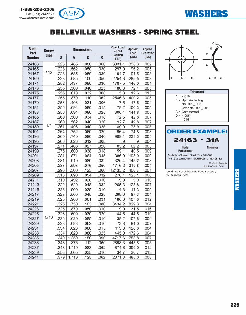
229
1-888-208-2008Fax (973) 244-9177
www.accuratescrew.com WASHERS
BELLEVILLE WASHERS - SPRING STEEL
24163 .223 .485 .080 .060 3331.1 396.3 .00224165 .223 .562 .050 .030 297.9 96.2 .00524167 .223 .685 .050 .030 194.7 94.5 .00824169 .223 .685 .100 .050 2254.3 285.5 .00324171 .252 .437 .090 .030 1787.5 146.0 .00124173 .255 .500 .040 .025 180.3 72.1 .00524175 .255 .610 .032 .008 5.8 12.6 .01324177 .255 .870 .110 .062 2546.3 400.2 .00524179 .256 .406 .031 .006 7.5 17.5 .00424181 .256 .694 .080 .015 78.2 106.3 .00524183 .256 .694 .080 .025 306.4 144.8 .00524185 .260 .500 .034 .018 72.6 42.8 .00724187 .260 .562 .040 .020 92.7 49.8 .00724189 .261 .493 .040 .025 189.9 75.9 .00524191 .264 .752 .060 .020 96.4 74.8 .00824193 .265 .740 .090 .040 999.1 233.3 .00524195 .266 .626 .012 .008 .9 .9 .00424197 .271 .406 .027 .020 85.2 62.2 .00524199 .275 .600 .038 .018 59.1 40.5 .00924201 .281 .871 .064 .045 386.0 195.9 .00924203 .281 .910 .080 .032 320.4 145.2 .00824205 .283 .593 .076 .050 1716.2 319.8 .00424207 .296 .500 .125 .060 12133.2 400.7 .00124209 .316 .690 .054 .032 276.1 125.1 .00824211 .319 .492 .020 .010 9.9 9.9 .01024213 .322 .620 .048 .032 265.3 128.8 .00724215 .323 .500 .025 .010 14.3 14.3 .00924217 .323 .500 .045 .025 299.0 87.3 .00424219 .323 .906 .061 .031 186.0 107.8 .01224221 .325 .750 .103 .086 3434.2 829.3 .00424223 .325 .870 .050 .010 9.0 31.5 .01624225 .326 .600 .030 .020 44.5 44.5 .01024227 .326 .620 .085 .010 38.2 107.8 .00424229 .328 .688 .062 .016 73.8 84.0 .00724231 .334 .620 .080 .015 113.8 126.6 .00424233 .334 .620 .080 .025 445.0 172.6 .00424235 .340 1.250 .150 .090 4717.6 753.8 .00724236 .343 .875 .112 .060 2898.3 445.8 .00524237 .348 1.119 .083 .062 674.6 399.0 .01224239 .353 .665 .035 .016 34.7 30.7 .01324241 .379 1.110 .125 .062 2071.3 485.0 .008
#12
1/4
5/16
BasicPart
Number
ScrewSize B
Dimensions
A D C
Calc. Loadat Flat
Position(LBS)
Approx.Load(LBS)
Approx.Deflection
(INS)
TolerancesA = +.010B = Up to/including
No. 10: +.005Over No. 10: +.010
C = CommercialD = +.005
-.015
*Load and deflection data does not applyto Stainless Steel.
ORDER EXAMPLE:24163
BasicPart Number
31AThickness
-
Available in Stainless Steel* Type 301-304.Add SS to part number. EXAMPLE: 24163-SS-12
301-304Stainless Steel
PassivateFinish
WA
SH
ER
S

230
1-888-208-2008Fax (973) 244-9177www.accuratescrew.comWASHERS
BELLEVILLE WASHERS - SPRING STEEL
BasicPart
Number
ScrewSize B
Dimensions
A D C
Calc. Loadat Flat
Position(LBS)
Approx.Load(LBS)
Approx.Deflection
(INS)
TolerancesA = +.010B = Up to/including
No. 10: +.005Over No. 10: +.010
C = CommercialD = +.005
-.015
*Load and deflection data does not applyto Stainless Steel.
ORDER EXAMPLE:24243
BasicPart Number
31AThickness
-
Available in Stainless Steel* Type 301-304.Add SS to part number. EXAMPLE: 24243-SS-12
301-304Stainless Steel
PassivateFinish
24243 .380 .750 .055 .040 327.0 203.9 .00924245 .382 .683 .080 .015 96.5 131.1 .00524247 .382 .683 .080 .025 378.1 178.7 .00524249 .382 .741 .055 .040 339.1 211.4 .00924251 .390 .625 .045 .022 143.4 71.8 .00724253 .390 .740 .060 .040 459.1 205.6 .00824255 .390 .740 .080 .062 1538.7 536.9 .00624257 .390 1.100 .080 .050 529.1 265.9 .01324259 .390 1.500 .095 .036 206.4 168.0 .01924261 .395 1.242 .135 .080 3084.8 688.0 .00924263 .402 .787 .053 .032 213.9 129.0 .01124265 .402 1.100 .069 .032 171.8 118.5 .01624267 .402 1.100 .069 .040 263.0 169.9 .01624269 .405 .875 .110 .062 2736.7 510.2 .00624271 .406 .607 .045 .018 107.5 61.0 .00624273 .406 1.000 .090 .062 1169.5 419.5 .00924275 .406 1.180 .092 .062 873.5 388.6 .01224277 .406 1.187 .129 .109 3125.1 1270.2 .00824279 .406 1.250 .096 .072 970.1 545.0 .01324283 .440 .785 .080 .015 73.1 132.8 .00724285 .440 .785 .080 .025 286.7 180.8 .00724287 .448 .860 .062 .031 243.4 132.2 .01124289 .450 .785 .070 .040 653.0 210.4 .00724291 .500 1.109 .035 .010 3.6 6.1 .02524293 .504 1.000 .080 .015 41.9 115.2 .01224295 .504 1.000 .080 .025 164.1 156.5 .01224297 .504 1.000 .085 .035 409.5 217.7 .01124299 .505 1.250 .135 .062 1948.9 564.5 .01024301 .515 1.250 .112 .065 1453.4 497.1 .01224303 .515 1.475 .110 .060 845.9 397.0 .01724305 .516 1.500 .250 .112 14658.3 1787.9 .00724307 .531 1.625 .162 .134 4319.2 1887.3 .01224309 .545 1.547 .125 .083 1711.9 735.8 .01624311 .562 1.625 .139 .109 2504.3 1287.7 .01524313 .562 1.625 .187 .093 4873.8 1141.2 .01224315 .563 1.340 .095 .050 554.2 307.8 .01824317 .563 1.573 .107 .050 492.3 302.8 .02124319 .567 1.125 .075 .040 338.1 204.1 .01624321 .635 1.250 .082 .040 330.1 219.1 .01924323 .700 1.067 .110 .060 2318.7 570.0 .00824325 .700 1.360 .080 .040 267.7 200.5 .023
1/2
7/16
3/8
WA
SH
ER
S

231
1-888-208-2008Fax (973) 244-9177
www.accuratescrew.com WASHERS
BELLEVILLE WASHERS - SPRING STEEL
24327 .760 1.500 .093 .045 372.5 265.7 .02424329 .770 1.250 .050 .020 34.6 35.1 .03024331 .770 1.500 .125 .062 1288.8 574.6 .01724333 .781 1.343 .110 .062 1346.9 535.3 .01424335 .803 1.570 .104 .060 743.0 462.0 .02324337 .812 1.180 .033 .012 6.8 7.6 .02124339 .817 2.362 .171 .080 1421.5 788.7 .02924341 .830 1.248 .043 .016 17.7 19.2 .02724343 .960 1.250 .065 .005 1.6 40.9 .01724345 1.004 1.554 .050 .020 23.7 24.1 .03024347 1.010 2.000 .130 .065 853.6 557.1 .03024349 1.031 1.500 .065 .032 126.4 126.4 .03324351 1.093 1.565 .047 .018 18.6 19.7 .02924353 1.120 1.382 .096 .032 440.5 457.1 .00924355 1.120 2.250 .103 .062 366.2 366.2 .04124357 1.260 2.000 .122 .062 827.6 559.1 .03024359 1.260 2.500 .160 .080 1252.1 847.0 .03924361 1.270 2.060 .085 .040 153.1 153.1 .04524363 1.390 2.700 .100 .060 – – –24365 1.484 1.995 .080 .030 104.9 113.2 .045
3/4
BasicPart
Number
ScrewSize B
Dimensions
A D C
Calc. Loadat Flat
Position(LBS)
Approx.Load(LBS)
Approx.Deflection
(INS)
TolerancesA = +.010B = Up to/including
No. 10: +.005Over No. 10: +.010
C = CommercialD = +.005
-.015
*Load and deflection data does not applyto Stainless Steel.
ORDER EXAMPLE:24327
BasicPart Number
31AThickness
-
Available in Stainless Steel* Type 301-304.Add SS to part number. EXAMPLE: 24327-SS-12
301-304Stainless Steel
PassivateFinish
1.00
WA
SH
ER
S! TECH TIP
Nylon locking elements prevent screws andfasteners from backing out due to vibration.

232
1-888-208-2008Fax (973) 244-9177www.accuratescrew.comWASHERS
CYLINDRICALLY CURVED WASHERSSPRING STEEL
DimensionsBasicPart
Number
ScrewSize B
IDA
OD D C
Calc. Loadat flat
pos. (LBS)
ApproxDeflection
(INS)24417 .040 .105 .018 .006 3.2 .00224419 .043 .088 .015 .004 1.2 .00224421 .047 .120 .025 .004 1.4 .00424423 .047 .120 .032 .004 1.4 .00424425 .051 .378 .047 .005 3.1 .03524427 .052 .133 .035 .005 2.2 .00424429 .055 .240 .040 .015 25.4 .00524431 .055 .350 .060 .005 3.0 .03024433 .059 .183 .047 .005 2.4 .00824435 .064 .130 .025 .006 2.6 .00324437 .064 .130 .032 .006 2.6 .00324439 .064 .250 .030 .003 0.9 .02524441 .064 .379 .047 .010 12.1 .01824443 .065 .133 .037 .008 4.7 .00324445 .065 .371 .065 .018 39.1 .00924447** .067 .600 .100 .004 1.8 .09624449 .068 .145 .030 .005 1.9 .00524451 .070 .240 .055 .005 2.5 .01424453 .075 .158 .047 .003 0.6 .01024455 .084 .130 .035 .008 3.3 .00324459 .092 .163 .047 .005 1.5 .00624461 .093 .170 .026 .004 1.0 .00924463 .095 .312 .077 .007 4.9 .01724465 .095 .320 .055 .008 6.6 .01624467 .096 .140 .031 .003 0.4 .00824469 .096 .250 .040 .005 2.2 .01524471 .097 .193 .047 .005 1.8 .00924473 .097 .193 .047 .010 7.2 .00524475 .097 .210 .040 .010 7.8 .00524477 .097 .302 .030 .006 3.5 .01924479 .097 .302 .030 .008 8.0 .01224481 .098 .403 .047 .006 3.9 .03324483 .098 .438 .060 .010 11.3 .02324485 .099 .205 .040 .010 7.5 .00524487 .100 .625 .090 .010 12.3 .04824489 .101 .147 .040 .005 1.1 .00524491 .109 .203 .032 .005 1.6 .01024493 .109 .250 .062 .005 2.0 .01524495 .112 .220 .025 .003 0.6 .02024497 .112 .240 .040 .010 7.8 .00724499 .112 .273 .047 .005 2.1 .01824501 .112 .375 .090 .005 2.5 .03424503 .112 .437 .090 .005 2.7 .04724505 .117 .313 .047 .008 5.8 .01524507 .118 .203 .032 .005 1.5 .01024509 .122 .250 .036 .016 19.2 .00524511 .122 .377 .060 .007 4.8 .025
#00
#0
#1
#2
** This item is available in Beryllium Copper only .
The cylindrically curved washer is well-suitedfor applications requiring flexibility and lightloads (from ounces up to about a hundredpounds), and repeated cycles through a rangeof motion. Of the cylindrically curved, waveand Belleville types, the cylindrically curvedwasher exhibits the most uniform springconstant over the widest range of deflection.
Spherically curved washers are frequentlymade as segments of spheres instead ofsegments of cylinders. Although they are nottrue conical washers, they haveapproximately the same springcharacteristics. However, the load capacity ofspherically curved washers variesconsiderably when deflected near the flatposition. The spherical shape tends to add astiffening effect so that, in general, sphericallycurved washers will have slightly higher springrates than comparable conical washers.
#3
#4*Load and deflection data does not apply toStainless Steel or Beryllium Copper.
Tolerances
A = +.010B = Up to/including
No. 10: +.005Over No. 10: +.010
C = CommercialD = +.010
ORDER EXAMPLE:24417
BasicPart Number
1Finish:
See page 277
-
Available in Stainless Steel* Type 17-7 Ph (heat treated).Add SS to part number. EXAMPLE: 24417-SS-12
17-7Stainless Steel
PassivateFinish
Available in Beryllium Copper* ASTM-B194 (heat treated).Add BC to part number. EXAMPLE: 24417-BC-1
Beryllium Copper
WA
SH
ER
S

233
1-888-208-2008Fax (973) 244-9177
www.accuratescrew.com WASHERS
CYLINDRICALLY CURVED WASHERSSPRING STEEL
DimensionsBasicPart
Number
ScrewSize B
IDA
OD D C
Calc. Loadat flat
pos. (LBS)
ApproxDeflection
(INS)24513 .122 .378 .047 .008 6.3 .02224515 .125 .247 .062 .003 0.6 .02524517 .125 .247 .062 .005 1.8 .01524519 .125 .250 .047 .008 4.6 .01024521 .125 .250 .047 .012 10.5 .00624523 .125 .406 .070 .008 6.4 .02524525 .126 .213 .035 .005 1.4 .01124527 .127 .176 .032 .010 4.0 .00424529 .127 .213 .018 .005 1.4 .01124531 .127 .406 .050 .005 2.5 .04024470 .127 .500 .068 .012 – –24533 .128 .198 .040 .008 3.3 .00624535 .128 .230 .047 .008 4.1 .00824537 .128 .240 .041 .005 1.7 .01424539 .128 .240 .041 .008 4.3 .00924541 .128 .250 .025 .012 10.3 .00624543 .128 .750 .030 .005 – –24545 .130 .219 .032 .007 2.9 .00824549 .130 .468 .060 .005 2.6 .05424551 .130 .687 .060 .010 10.3 .05024553 .132 .503 .078 .010 10.8 .03124555 .133 .285 .062 .006 2.8 .01724557 .134 .437 .094 .010 10.1 .02324559 .135 .245 .032 .006 2.3 .01224561 .135 .285 .062 .006 2.7 .01724563 .136 .312 .062 .006 2.9 .02024565 .136 .312 .062 .010 8.2 .01224567 .136 .370 .035 .008 5.9 .02124569 .136 .400 .065 .010 9.6 .02024571 .137 .250 .020 .005 1.6 .01524573 .137 .253 .047 .005 1.6 .01624575 .137 .283 .047 .008 4.8 .01224577 .137 .283 .062 .005 1.8 .02024579 .137 .283 .062 .010 7.5 .01024581 .139 .317 .062 .010 8.2 .01224583 .140 .365 .065 .005 2.2 .03324585 .140 .406 .060 .005 2.4 .04024587 .140 .490 .080 .020 41.9 .01524589 .140 .562 .060 .012 15.8 .03224591 .141 .213 .048 .008 3.1 .00724593 .141 .281 .047 .008 4.6 .01224595 .141 .373 .062 .010 9.1 .01724597 .141 .467 .058 .010 10.2 .02724599 .144 .312 .047 .016 20.2 .00724601 .144 .312 .048 .016 20.2 .00724603 .145 .312 .030 .003 0.4 .02724605 .145 .490 .080 .005 2.5 .059
#4
#5
#6
*Load and Deflection data does not apply toStainless Steel or Beryllium Copper.
Tolerances
A = +.010B = Up to/including
No. 10: +.005Over No. 10: +.010
C = CommercialD = +.010
ORDER EXAMPLE:24513
BasicPart Number
1Finish:
See page 277
-
Available in Stainless Steel* Type 17-7 Ph (heat treated).Add SS to part number. EXAMPLE: 24513-SS-12
17-7Stainless Steel
PassivateFinish
Available in Beryllium Copper* ASTM-B194 (heat treated).Add BC to part number. EXAMPLE: 24513-BC-1
Beryllium Copper WA
SH
ER
S
! TECHTIPThe cylindricallycurved washer iswell-suited forapplicationsrequiring flexibilityand light loads(from ouncesup to about ahundred pounds).
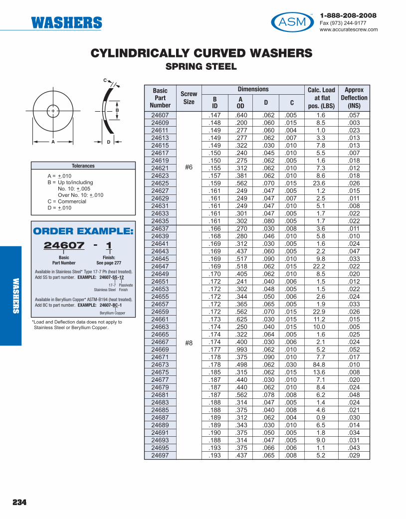
234
1-888-208-2008Fax (973) 244-9177www.accuratescrew.comWASHERS
WA
SH
ER
S
CYLINDRICALLY CURVED WASHERSSPRING STEEL
DimensionsBasicPart
Number
ScrewSize B
IDA
OD D C
Calc. Loadat flat
pos. (LBS)
ApproxDeflection
(INS)24607 .147 .640 .062 .005 1.6 .05724609 .148 .200 .060 .015 8.5 .00324611 .149 .277 .060 .004 1.0 .02324613 .149 .277 .062 .007 3.3 .01324615 .149 .322 .030 .010 7.8 .01324617 .150 .240 .045 .010 5.5 .00724619 .150 .275 .062 .005 1.6 .01824621 .155 .312 .062 .010 7.3 .01224623 .157 .381 .062 .010 8.6 .01824625 .159 .562 .070 .015 23.6 .02624627 .161 .249 .047 .005 1.2 .01524629 .161 .249 .047 .007 2.5 .01124631 .161 .249 .047 .010 5.1 .00824633 .161 .301 .047 .005 1.7 .02224635 .161 .302 .080 .005 1.7 .02224637 .166 .270 .030 .008 3.6 .01124639 .168 .280 .046 .010 5.8 .01024641 .169 .312 .030 .005 1.6 .02424643 .169 .437 .060 .005 2.2 .04724645 .169 .517 .090 .010 9.8 .03324647 .169 .518 .062 .015 22.2 .02224649 .170 .405 .062 .010 8.5 .02024651 .172 .241 .040 .006 1.5 .01224653 .172 .302 .048 .005 1.5 .02224655 .172 .344 .050 .006 2.6 .02424657 .172 .365 .065 .005 1.9 .03324659 .172 .562 .070 .015 22.9 .02624661 .173 .625 .030 .015 11.2 .01524663 .174 .250 .040 .015 10.0 .00524665 .174 .322 .064 .005 1.6 .02524667 .174 .400 .030 .006 2.1 .02424669 .177 .993 .062 .010 5.2 .05224671 .178 .375 .090 .010 7.7 .01724673 .178 .498 .062 .030 84.8 .01024675 .185 .315 .062 .015 13.6 .00824677 .187 .440 .030 .010 7.1 .02024679 .187 .440 .062 .010 8.4 .02424681 .187 .562 .078 .008 6.2 .04824683 .188 .314 .047 .005 1.4 .02424685 .188 .375 .040 .008 4.6 .02124687 .189 .312 .062 .004 0.9 .03024689 .189 .343 .030 .010 6.5 .01424691 .190 .375 .050 .005 1.8 .03424693 .188 .314 .047 .005 9.0 .03124695 .193 .375 .066 .006 1.1 .04324697 .193 .437 .065 .008 5.2 .029
#6
#8
*Load and Deflection data does not apply toStainless Steel or Beryllium Copper.
Tolerances
A = +.010B = Up to/including
No. 10: +.005Over No. 10: +.010
C = CommercialD = +.010
ORDER EXAMPLE:24607
BasicPart Number
1Finish:
See page 277
-
Available in Stainless Steel* Type 17-7 Ph (heat treated).Add SS to part number. EXAMPLE: 24607-SS-12
17-7Stainless Steel
PassivateFinish
Available in Beryllium Copper* ASTM-B194 (heat treated).Add BC to part number. EXAMPLE: 24607-BC-1
Beryllium Copper

235
1-888-208-2008Fax (973) 244-9177
www.accuratescrew.com WASHERS
CYLINDRICALLY CURVED WASHERSSPRING STEEL
DimensionsBasicPart
Number
ScrewSize B
IDA
OD D C
Calc. Loadat flat
pos. (LBS)
ApproxDeflection
(INS)24699 .194 .370 .050 .008 4.4 .02124701 .194 .375 .070 .006 2.5 .02924703 .194 .630 .090 .020 40.6 .02424705 .195 .277 .060 .005 1.0 .01924707 .195 .312 .030 .010 5.5 .01224709 .195 .400 .060 .016 19.2 .01224711 .195 .490 .030 .010 6.0 .02024713 .195 .562 .070 .008 6.1 .04824715 .196 .750 .093 .020 43.3 .03424717 .198 .442 .062 .010 8.0 .02424719 .199 .375 .041 .010 6.8 .01724721 .199 .443 .055 .005 2.0 .04824723 .200 .302 .045 .005 1.2 .02224725 .200 .430 .070 .010 7.8 .02324727 .200 .990 .062 .010 5.0 .05224729 .201 .300 .050 .010 4.8 .01124731 .201 .374 .065 .005 1.6 .03424733 .202 .312 .062 .010 5.1 .01224735 .202 .505 .062 .005 2.0 .05724737 .202 .505 .062 .012 12.6 .02624480 .203 .322 .060 .015 – –24739 .203 .365 .032 .005 1.3 .02725100 .203 .375 .062 .005 1.6 .03425102 .203 .375 .062 .010 6.7 .01725104 .203 .406 .047 .005 1.8 .04025106 .203 .438 .070 .010 7.8 .02325108 .203 .500 .080 .015 19.6 .02025110 .203 .501 .074 .015 19.6 .02025112 .204 .438 .070 .010 7.8 .02325114 .204 .565 .052 .025 58.5 .01625116 .204 .640 .045 .005 0.9 .04025118 .205 .369 .080 .005 1.6 .03325120 .205 .500 .080 .015 19.4 .02025122 .205 1.010 .085 .063 463.9 .02025124 .208 .563 .062 .012 13.3 .03225126 .220 .406 .060 .005 1.6 .04025128 .220 .740 .130 .010 10.3 .06725130 .228 .375 .041 .010 5.7 .01725132 .228 .468 .125 .016 19.2 .01725134 .231 .423 .050 .010 6.6 .02225136 .234 .438 .077 .010 6.8 .02325138 .234 .630 .062 .012 13.2 .04025140 .235 .325 .047 .010 4.0 .01325142 .235 .410 .062 .010 6.2 .02125144 .239 .438 .095 .010 6.6 .02325146 .239 .500 .050 .015 17.2 .02025148 .239 .625 .100 .015 20.3 .032
#10
#12
*Load and Deflection data does not apply toStainless Steel or Beryllium Copper.
Tolerances
A = +.010B = Up to/including
No. 10: +.005Over No. 10: +.010
C = CommercialD = +.010
ORDER EXAMPLE:24699
BasicPart Number
1Finish:
See page 277
-
Available in Stainless Steel* Type 17-7 Ph (heat treated).Add SS to part number. EXAMPLE: 24699-SS-12
17-7Stainless Steel
PassivateFinish
Available in Beryllium Copper* ASTM-B194 (heat treated).Add BC to part number. EXAMPLE: 24699-BC-1
Beryllium Copper
WA
SH
ER
S
! TECHTIPThe cylindricallycurved washerexhibits themost uniformspring constantover the widestrange ofdeflection.

236
1-888-208-2008Fax (973) 244-9177www.accuratescrew.comWASHERS
WA
SH
ER
S
CYLINDRICALLY CURVED WASHERSSPRING STEEL
DimensionsBasicPart
Number
ScrewSize B
IDA
OD D C
Calc. Loadat flat
pos. (LBS)
ApproxDeflection
(INS)25150 .250 .437 .047 .010 6.2 .02325152 .250 .437 .090 .010 6.2 .02325154 .250 .495 .125 .007 3.5 .04325156 .250 .500 .078 .006 2.6 .05125158 .250 .562 .078 .020 32.5 .01925160 .250 .625 .078 .020 35.2 .02425162 .251 .562 .037 .007 2.1 .03025164 .251 .750 .070 .030 87.8 .02325166 .252 1.065 .093 .015 21.2 .07825168 .253 .406 .030 .005 0.8 .02525170 .253 .469 .047 .010 6.7 .02725172 .254 .497 .100 .006 2.5 .05025174 .254 .497 .100 .010 7.1 .03025176 .255 .750 .093 .012 13.9 .05725178 .256 .406 .032 .006 1.5 .02625180 .257 .438 .040 .005 1.1 .03525182 .257 .438 .047 .015 13.6 .01625184 .258 .680 .080 .010 9.1 .05725186 .259 .406 .062 .018 17.2 .01125188 .259 .562 .080 .018 25.6 .02125190 .259 .691 .070 .006 2.1 .06425192 .260 .495 .125 .007 3.4 .04325194 .260 .508 .055 .015 16.1 .02125196 .261 .740 .130 .010 9.4 .06725198 .261 .875 .060 .030 89.0 .03025200 .262 .378 .062 .005 1.1 .03525202 .262 .378 .062 .010 4.5 .01725204 .262 .438 .050 .010 5.8 .02325206 .262 .562 .060 .008 5.0 .04825208 .263 .433 .047 .005 1.3 .04225210 .263 .433 .047 .008 3.6 .02925212 .263 .433 .047 .015 12.9 .01525214 .263 .437 .062 .005 1.4 .04725216 .263 .437 .062 .008 3.7 .02925218 .263 .437 .062 .012 8.4 .01925220 .265 .406 .044 .010 5.0 .02025222 .265 .406 .062 .010 5.0 .02025224 .265 .490 .092 .008 4.3 .03725226 .265 .500 .070 .020 27.5 .01525228 .265 .508 .093 .010 7.0 .03225230 .265 .508 .093 .015 15.7 .02125232 .265 .508 .093 .028 59.0 .01125234 .265 .552 .075 .008 4.8 .04725236 .265 .562 .125 .025 48.4 .01525238 .265 .625 .075 .015 19.0 .03225240 .269 .435 .068 .010 5.5 .02325242 .270 .380 .060 .010 4.2 .018
#14
1/4*Load and Deflection data does not apply toStainless Steel or Beryllium Copper.
Tolerances
A = +.010B = Up to/including
No. 10: +.005Over No. 10: +.010
C = CommercialD = +.010
ORDER EXAMPLE:25150
BasicPart Number
1Finish:
See page 277
-
Available in Stainless Steel* Type 17-7 Ph (heat treated).Add SS to part number. EXAMPLE: 25150-SS-12
17-7Stainless Steel
PassivateFinish
Available in Beryllium Copper* ASTM-B194 (heat treated).Add BC to part number. EXAMPLE: 25150-BC-1
Beryllium Copper

237
1-888-208-2008Fax (973) 244-9177
www.accuratescrew.com WASHERS
CYLINDRICALLY CURVED WASHERSSPRING STEEL
DimensionsBasicPart
Number
ScrewSize B
IDA
OD D C
Calc. Loadat flat
pos. (LBS)
ApproxDeflection
(INS)25244 .270 .500 .060 .010 6.7 .03125246 .270 .500 .060 .020 26.9 .01525248 .272 .496 .060 .010 6.6 .03025250 .275 .599 .055 .010 7.9 .04425252 .275 .600 .035 .018 17.9 .01725254 .280 .375 .030 .005 0.6 .02525256 .280 .500 .090 .010 6.4 .03125258 .280 .552 .075 .015 16.2 .02525260 .280 .625 .093 .006 2.9 .08025262 .280 .625 .093 .008 5.1 .06025264 .280 .625 .093 .010 8.0 .04825266 .280 .625 .093 .012 11.6 .04025268 .280 .625 .093 .015 18.2 .03225270 .280 .625 .093 .020 32.3 .02425272 .280 .740 .135 .010 9.1 .06725274 .290 .437 .060 .005 1.2 .04725276 .296 .551 .085 .010 6.7 .03725278 .301 .671 .093 .012 11.6 .04625280 .312 .562 .093 .020 26.0 .01925282 .315 .500 .060 .010 5.4 .03125284 .315 .625 .062 .010 7.2 .04825286 .315 .625 .095 .010 7.2 .04825288 .316 .490 .040 .010 5.2 .02925290 .316 .625 .098 .020 29.0 .02425292 .319 .500 .075 .015 11.9 .02025294 .320 .625 .080 .012 10.3 .04025296 .320 .688 .080 .010 7.8 .05825298 .323 .415 .062 .003 0.2 .05925300 .323 .415 .062 .008 2.0 .02625302 .323 .415 .062 .015 7.3 .01425304 .326 .490 .062 .010 4.9 .02925306 .326 1.000 .093 .050 247.1 .02425308 .327 .620 .085 .010 6.9 .04725310 .328 .500 .080 .008 3.2 .03825312 .328 .562 .080 .008 3.9 .04825314 .328 .562 .125 .025 38.1 .01525316 .330 .750 .187 .030 73.9 .02325318 .330 .875 .040 .010 2.9 .03025320 .331 .622 .093 .006 2.4 .07925322 .331 .622 .093 .012 9.8 .03925324 .331 .622 .093 .015 15.4 .03225326 .331 .622 .093 .025 42.8 .01925328 .346 .761 .187 .020 31.9 .03525330 .363 .672 .080 .015 15.1 .03725332 .375 .600 .070 .025 34.3 .01825334 .375 .750 .140 .020 29.3 .03425336 .375 .870 .109 .010 8.3 .093
1/4
5/16
*Load and Deflection data does not apply toStainless Steel or Beryllium Copper.
Tolerances
A = +.010B = Up to/including
No. 10: +.005Over No. 10: +.010
C = CommercialD = +.010
ORDER EXAMPLE:25244
BasicPart Number
1Finish:
See page 277
-
Available in Stainless Steel* Type 17-7 Ph (heat treated).Add SS to part number. EXAMPLE: 25244-SS-12
17-7Stainless Steel
PassivateFinish
Available in Beryllium Copper* ASTM-B194 (heat treated).Add BC to part number. EXAMPLE: 25244-BC-1
Beryllium Copper WA
SH
ER
S

238
1-888-208-2008Fax (973) 244-9177www.accuratescrew.comWASHERS
WA
SH
ER
S
25338 .377 .465 .093 .006 0.9 .04424664 .378 .562 .080 .010 – –25340 .378 .685 .100 .005 1.3 .09525342 .379 .500 .070 .010 3.5 .03125344 .379 .563 .080 .010 4.7 .03925346 .379 .563 .080 .020 19.1 .01925348 .379 .686 .093 .010 6.5 .05825350 .383 .625 .078 .010 5.6 .04825352 .383 .691 .070 .008 3.5 .06225354 .385 .687 .040 .016 10.9 .02425356 .390 .553 .075 .006 1.5 .06225358 .390 .740 .140 .010 6.9 .06725360 .390 .740 .140 .020 27.7 .03325362 .391 .656 .125 .025 37.0 .02125364 .400 .600 .093 .012 7.0 .03725366 .406 .524 .060 .010 3.3 .03425368 .438 .740 .140 .015 13.4 .04525370 .439 .623 .093 .012 6.2 .04025372 .455 .740 .140 .010 5.6 .06725374 .468 .686 .130 .005 1.1 .11525376 .470 .870 .116 .010 6.7 .09325378 .474 .709 .115 .015 10.9 .04125380 .477 .708 .120 .010 4.17 .06125382 .502 1.003 .093 .012 8.3 .08125384 .504 .938 .100 .032 69.4 .03425386 .505 .740 .125 .010 4.6 .06725388 .505 .740 .130 .015 10.4 .04525390 .505 .815 .093 .029 46.9 .02825394 .514 .874 .032 .020 6.2 .01225396 .515 .875 .125 .015 13.5 .06225398 .516 .744 .093 .010 4.4 .06825402 .520 .870 .109 .010 5.9 .09325404 .525 .980 .110 .021 30.0 .05625406 .531 .873 .156 .010 5.7 .09325408 .537 .753 .093 .012 6.0 .05825410 .585 .875 .135 .010 4.8 .09425412 .600 .850 .080 .020 17.2 .04425414 .614 .880 .062 .020 15.7 .04225416 .640 .750 .050 .010 1.2 .04025418 .640 .875 .060 .010 2.1 .05025420 .640 1.000 .100 .030 47.5 .04125422 .658 1.750 .219 .020 36.6 .18725424 .665 .980 .100 .020 18.8 .05925426 .720 1.000 .150 .015 9.2 .08125428 .765 .910 .100 .020 9.3 .05125430 .890 1.093 .130 .010 2.2 .12025432 .890 1.095 .093 .032 28.1 .046
7/16
3/8
5/16
CYLINDRICALLY CURVED WASHERSSPRING STEEL
DimensionsBasicPart
Number
ScrewSize B
IDA
OD D C
Calc. Loadat flat
pos. (LBS)
ApproxDeflection
(INS)
*Load and Deflection data does not apply toStainless Steel or Beryllium Copper.
Tolerances
A = +.010B = Up to/including
No. 10: +.005Over No. 10: +.010
C = CommercialD = +.010
ORDER EXAMPLE:25338
BasicPart Number
1Finish:
See page 277
-
Available in Stainless Steel* Type 17-7 Ph (heat treated).Add SS to part number. EXAMPLE: 25338-SS-12
17-7Stainless Steel
PassivateFinish
Available in Beryllium Copper* ASTM-B194 (heat treated).Add BC to part number. EXAMPLE: 25338-BC-1
Beryllium Copper
1/2
5/8
3/4
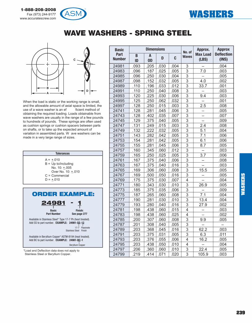
239
1-888-208-2008Fax (973) 244-9177
www.accuratescrew.com WASHERS
WAVE WASHERS - SPRING STEEL
24981 .093 .205 .030 .004 3 – .00424983 .096 .187 .025 .005 3 7.0 .00324985 .096 .250 .030 .004 3 – .00524987 .098 .152 .032 .005 3 4.0 .00224989 .110 .196 .033 .012 3 33.7 .00124991 .110 .250 .040 .008 3 – .00324993 .120 .225 .030 .006 3 9.4 .00324995 .125 .250 .062 .032 3 – .00124997 .128 .250 .015 .003 3 2.5 .00824741 .128 .281 .045 .006 3 – .00524743 .128 .402 .035 .007 3 – .00724745 .129 .375 .040 .005 3 – .00924747 .131 .249 .015 .003 3 2.4 .00824749 .132 .222 .032 .005 3 5.1 .00424751 .143 .282 .042 .005 3 7.1 .00624753 .154 .281 .042 .005 3 6.1 .00624755 .155 .281 .045 .006 3 8.7 .00524757 .160 .345 .060 .012 3 – .00324759 .165 .250 .025 .005 3 3.7 .00624761 .167 .375 .040 .006 3 – .00824763 .167 .375 .040 .016 3 – .00324765 .169 .306 .060 .008 3 15.5 .00524767 .169 .500 .050 .016 3 – .00524769 .175 .375 .030 .007 4 – .00424771 .180 .343 .030 .010 3 26.9 .00524773 .185 .375 .035 .006 3 – .00924775 .187 .265 .060 .008 3 7.1 .00424777 .190 .281 .030 .010 3 13.4 .00424779 .193 .280 .040 .016 3 27.9 .00224781 .198 .438 .060 .015 4 – .00324783 .198 .438 .060 .025 4 – .00224785 .200 .307 .060 .008 3 9.9 .00524787 .201 .308 .040 .005 3 – –24789 .203 .368 .045 .016 3 62.2 .00324791 .203 .375 .031 .005 3 6.3 .01124793 .203 .376 .055 .006 4 16.2 .00524795 .203 .438 .050 .010 4 – .00424797 .206 .360 .060 .010 3 22.4 .00524799 .219 .414 .071 .020 3 105.9 .003
BasicPart
Number
DimensionsNo. ofWavesB
IDA
OD D C
Approx.Max Load
(LBS)
ApproxDeflection
(INS)
When the load is static or the working range is small,and the allowable amount of axial space is limited, theuse of a wave washer is an ef ficient method ofobtaining the required loading. Loads obtainable fromwave washers are usually in the range of a few poundsto hundreds of pounds. These springs are often usedas cushion springs or cushion spacers between partson shafts, or to take up the expected amount ofvariation in assembled parts. W ave washers can bemade in a very large range of sizes.
*Load and Deflection data does not apply toStainless Steel or Beryllium Copper.
Tolerances
A = +.010B = Up to/including
No. 10: +.005Over No. 10: +.010
C = CommercialD = +.010
ORDER EXAMPLE:24981
BasicPart Number
1Finish:
See page 277
-
Available in Stainless Steel* Type 17-7 Ph (heat treated).Add SS to part number. EXAMPLE: 24981-SS-12
17-7Stainless Steel
PassivateFinish
Available in Beryllium Copper* ASTM-B194 (heat treated).Add BC to part number. EXAMPLE: 24981-BC-1
Beryllium CopperW
AS
HE
RS

240
1-888-208-2008Fax (973) 244-9177www.accuratescrew.comWASHERS
WA
SH
ER
S
WAVE WASHERS - SPRING STEEL
24801 .221 .374 .050 .010 3 20.7 .00624803 .252 .750 .086 .012 3 – .01424805 .255 .345 .030 .008 3 5.5 .00824807 .265 .365 .030 .006 3 3.4 .01124809 .265 .375 .030 .010 4 19.6 .00424811 .265 .406 .030 .016 3 34.6 .00524813 .265 .432 .045 .016 3 42.1 .00524815 .265 .500 .045 .006 3 9.5 .01624817 .265 .500 .045 .008 3 16.8 .01224819 .265 .500 .045 .010 3 26.3 .01024821 .265 .500 .045 .016 3 59.3 .00724823 .265 .562 .070 .010 3 – .01124825 .288 .410 .062 .005 3 2.8 .00624827 .290 .531 .070 .010 3 24.8 .01124829 .312 .463 .031 .016 4 54.6 .00424831 .312 .463 .050 .020 4 97.2 .00324833 .322 .420 .040 .006 3 2.3 .01524835 .325 .500 .055 .008 3 10.0 .01424837 .325 .500 .055 .015 3 35.1 .00824839 .328 .682 .062 .010 3 – .01724841 .335 .562 .060 .010 4 36.0 .00824843 .346 .562 .080 .003 3 – –24845 .346 .562 .080 .005 3 4.6 .02824847 .346 .562 .080 .010 3 18.5 .01424849 .355 .500 .045 .005 3 2.7 .02424851 .355 .561 .080 .010 3 17.0 .01424853 .365 .485 .060 .006 3 2.7 .02024855 .382 .625 .080 .007 3 9.2 .02424857 .385 .500 .050 .005 3 1.5 .02624859 .385 .500 .050 .010 3 6.3 .01324861 .385 .531 .035 .010 3 9.6 .01524863 .386 .495 .050 .010 3 10.3 .01324865 .390 .562 .060 .010 3 12.0 .01524867 .390 .625 .080 .016 3 40.1 .01224869 .390 .655 .093 .010 3 20.3 .01824871 .390 .655 .110 .016 3 45.7 .01224873 .390 .655 .110 .020 3 81.2 .00924875 .406 .650 .085 .010 3 17.7 .01924877 .420 .524 .068 .003 3 0.8 .050
BasicPart
Number
DimensionsNo. ofWavesB
IDA
OD D C
Approx.Max Load
(LBS)
ApproxDeflection
(INS)
*Load and Deflection data does not apply toStainless Steel or Beryllium Copper.
Tolerances
A = +.010B = Up to/including
No. 10: +.005Over No. 10: +.010
C = CommercialD = +.010
ORDER EXAMPLE:24801
BasicPart Number
1Finish:
See page 277
-
Available in Stainless Steel* Type 17-7 Ph (heat treated).Add SS to part number. EXAMPLE: 24801-SS-12
17-7Stainless Steel
PassivateFinish
Available in Beryllium Copper* ASTM-B194 (heat treated).Add BC to part number. EXAMPLE: 24801-BC-1
Beryllium Copper
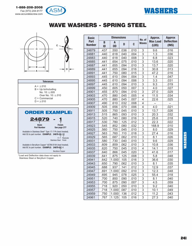
241
1-888-208-2008Fax (973) 244-9177
www.accuratescrew.com WASHERS
WAVE WASHERS - SPRING STEEL
24879 .437 .550 .036 .010 3 9.6 .01624881 .440 .618 .040 .004 3 1.3 .03624883 .440 .618 .040 .008 3 6.8 .02324885 .441 .654 .075 .010 3 13.6 .02024887 .441 .655 .094 .010 3 13.7 .02024889 .441 .655 .094 .016 3 30.8 .01324891 .441 .750 .080 .015 3 47.2 .01624893 .445 .610 .094 .004 3 1.4 .04724895 .445 .610 .094 .006 3 3.3 .03124897 .445 .610 .094 .010 3 9.3 .01924899 .450 .605 .050 .007 3 4.0 .02724901 .455 .870 .094 .010 3 27.0 .02924903 .470 .880 .045 .005 4 11.5 .03424905 .470 .880 .045 .007 4 22.6 .02524907 .490 .610 .032 .008 4 – –24909 .505 .656 .070 .006 4 4.0 .02124911 .505 .750 .045 .010 3 13.7 .02624913 .515 .865 .093 .010 3 20.3 .03224915 .520 .740 .080 .016 3 25.6 .01824917 .530 .780 .125 .012 3 22.3 .02224923 .545 .852 .080 .032 3 168.9 .01024925 .560 .750 .045 .010 3 8.0 .02924927 .563 .760 .110 .018 3 27.4 .01624929 .565 .687 .062 .010 3 8.1 .02624931 .580 .730 .040 .010 3 9.6 .02924933 .609 .859 .062 .010 3 10.8 .03624935 .620 .750 .045 .010 4 14.1 .01824937 .640 .866 .045 .020 3 41.6 .01724939 .641 .875 .125 .008 3 5.8 .04824941 .642 1.000 .105 .016 3 36.6 .03024943 .650 .790 .062 .010 3 8.1 .03524945 .688 .937 .141 .012 3 12.9 .03724947 .691 1.000 .092 .010 3 12.3 .04824949 .695 .945 .078 .025 3 55.4 .01824951 .700 .850 .090 .010 3 8.1 .04024953 .700 .875 .090 .007 3 4.5 .05924955 .718 .920 .050 .010 3 9.2 .04024957 .718 1.000 .087 .010 3 10.1 .04924959 .750 1.000 .136 .012 3 11.2 .04324961 .767 1.125 .105 .016 3 27.3 .040
BasicPart
Number
DimensionsNo. ofWavesB
IDA
OD D C
Approx.Max Load
(LBS)
ApproxDeflection
(INS)
*Load and Deflection data does not apply toStainless Steel or Beryllium Copper.
Tolerances
A = +.010B = Up to/including
No. 10: +.005Over No. 10: +.010
C = CommercialD = +.010
ORDER EXAMPLE:24879
BasicPart Number
1Finish:
See page 277
-
Available in Stainless Steel* Type 17-7 Ph (heat treated).Add SS to part number. EXAMPLE: 24879-SS-12
17-7Stainless Steel
PassivateFinish
Available in Beryllium Copper* ASTM-B194 (heat treated).Add BC to part number. EXAMPLE: 24879-BC-1
Beryllium Copper
WA
SH
ER
S

1-888-208-2008Fax (973) 244-9177www.accuratescrew.comWASHERS
WAVE WASHERS - SPRING STEEL
24963 .780 1.060 .120 .008 3 5.6 .07124965 .781 1.000 .080 .012 3 14.8 .04424967 .781 1.000 .080 .020 3 41.2 .02724969 .800 .900 .090 .018 3 15.9 .02724971 .812 .983 .080 .010 3 7.9 .05424973 .812 1.095 .062 .010 3 7.1 .05224975 .828 1.432 .125 .020 3 87.4 .04325000 .856 1.102 .075 .012 3 8.4 .05425002 .885 1.311 .125 .007 4 11.8 .06525004 .901 1.150 .060 .012 3 12.0 .04825096 .910 1.410 .120 .020 3 64.0 .04525008 .914 1.078 .120 .005 3 1.4 .11525010 .915 1.110 .120 .010 3 8.0 .06925012 .926 1.116 .090 .018 3 25.2 .03925014 .959 1.115 .055 .020 3 24.5 .03525016 .960 1.110 .048 .012 3 5.2 .03625018 .970 1.210 .062 .012 4 23.6 .03725020 1.014 1.245 .145 .028 3 67.2 .03125022 1.015 1.250 .050 .006 3 0.9 .04425024 1.016 1.437 .156 .012 3 15.9 .08425026 1.016 1.500 .085 .016 3 29.8 .07025028 1.044 1.235 .090 .018 3 22.7 .04825030 1.068 1.368 .072 .020 3 41.3 .05025032 1.093 1.365 .093 .012 3 12.8 .08125034 1.135 1.470 .062 .012 3 4.6 .05025036 1.185 1.437 .075 .020 3 30.7 .05525038 1.201 1.543 .105 .016 3 26.7 .07925040 1.250 1.453 .090 .016 4 28.6 .04325042 1.250 2.004 .140 .032 3 160.6 .05925044 1.310 1.556 .172 .020 3 28.7 .06925046** 1.437 1.690 .035 .005 4 – –25048** 1.500 1.820 .125 .010 4 – –25050 1.565 2.010 .150 .032 3 106.8 .06725052** 1.656 1.985 .045 .010 4 – –25054 1.700 1.800 .050 .025 4 14.4 .02525056 1.750 2.000 .150 .025 4 62.1 .05325058 1.781 2.000 .187 .020 4 34.5 .06725060 2.000 2.250 .200 .020 3 19.7 .15125062 2.032 2.875 .215 .016 4 44.2 .15125064 3.475 3.790 .100 .050 4 81.2 .050
BasicPart
Number
DimensionsNo. ofWavesB
IDA
OD D C
Approx.Max Load
(LBS)
ApproxDeflection
(INS)
*Load and Deflection data does not apply toStainless Steel or Beryllium Copper.
Tolerances
A = +.010B = Up to/including
No. 10: +.005Over No. 10: +.010
C = CommercialD = +.010
ORDER EXAMPLE:24963
BasicPart Number
1Finish:
See page 277
-
Available in Stainless Steel* Type 17-7 Ph (heat treated).Add SS to part number. EXAMPLE: 24963-SS-12
17-7Stainless Steel
PassivateFinish
Available in Beryllium Copper* ASTM-B194 (heat treated).Add BC to part number. EXAMPLE: 24963-BC-1
Beryllium Copper
**Beryllium Copper only.
242
! TECHTIPOur full thread captivescrew assemblies area good alternative toSEMS screws.
WA
SH
ER
S
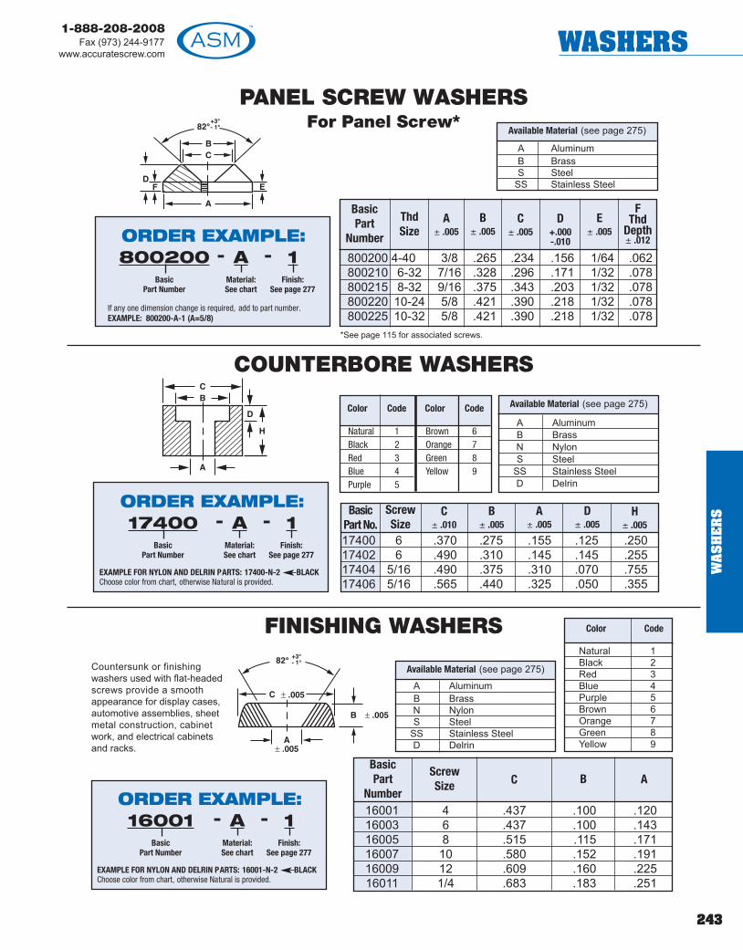
243
1-888-208-2008Fax (973) 244-9177
www.accuratescrew.com WASHERS
PANEL SCREW WASHERSFor Panel Screw*
COUNTERBORE WASHERS
FINISHING WASHERS
17400 6 .370 .275 .155 .125 .25017402 6 .490 .310 .145 .145 .25517404 5/16 .490 .375 .310 .070 .75517406 5/16 .565 .440 .325 .050 .355
BasicPart No.
ScrewSize
C± .010
B± .005
A± .005
D± .005
H± .005
16001 4 .437 .100 .12016003 6 .437 .100 .14316005 8 .515 .115 .17116007 10 .580 .152 .19116009 12 .609 .160 .22516011 1/4 .683 .183 .251
BasicPart
Number
ScrewSize C AB
800200 4-40 3/8 .265 .234 .156 1/64 .062800210 6-32 7/16 .328 .296 .171 1/32 .078800215 8-32 9/16 .375 .343 .203 1/32 .078800220 10-24 5/8 .421 .390 .218 1/32 .078800225 10-32 5/8 .421 .390 .218 1/32 .078
BasicPart
Number
ThdSize
A± .005
B± .005
C± .005
D+.000-.010
E± .005
FThd
Depth± .012
Countersunk or finishingwashers used with flat-headedscrews provide a smoothappearance for display cases,automotive assemblies, sheetmetal construction, cabinetwork, and electrical cabinetsand racks.
A AluminumB BrassN NylonS Steel
SS Stainless SteelD Delrin
Available Material (see page 275)
*See page 115 for associated screws.
Available Material (see page 275)
Natural 1Black 2Red 3Blue 4Purple 5
Brown 6Orange 7Green 8Yellow 9
Color Code Color Code
A AluminumB BrassN NylonS Steel
SS Stainless SteelD Delrin
Available Material (see page 275)
Natural 1Black 2Red 3Blue 4Purple 5Brown 6Orange 7Green 8Yellow 9
Color Code
ORDER EXAMPLE:-800200
BasicPart Number
AMaterial:See chart
1Finish:
See page 277
-
If any one dimension change is required, add to part number.EXAMPLE: 800200-A-1 (A=5/8)
ORDER EXAMPLE:-17400
BasicPart Number
AMaterial:See chart
1Finish:
See page 277
-
EXAMPLE FOR NYLON AND DELRIN PARTS: 17400-N-2 BLACKChoose color from chart, otherwise Natural is provided.
A AluminumB BrassS Steel
SS Stainless Steel
ORDER EXAMPLE:-16001
BasicPart Number
AMaterial:See chart
1Finish:
See page 277
-
EXAMPLE FOR NYLON AND DELRIN PARTS: 16001-N-2 BLACKChoose color from chart, otherwise Natural is provided.
WA
SH
ER
S

244
1-888-208-2008Fax (973) 244-9177www.accuratescrew.comNUTS & BUSHINGS
NU
TS
&B
US
HIN
GS
POTENTIOMETER, VOLUME CONTROL AND SWITCH NUTS
Hexagon
HT
* Normally stocked; others allow approximately2 weeks for delivery.
2-56 903000 3/16 1/163-48 903002 3/16 1/164-36 903004 1/4 3/324-40 903006 1/4 3/326-32 903008 5/16 7/648-32 903010 5/16 1/810-32 903012 5/16 1/812-24 903014 3/8 1/81/4-20 903016 7/16 3/161/4-28 903018 3/8 3/321/4-28 903020 3/8 1/81/4-28 903022 7/16 .1001/4-32 903024 5/16 1/161/4-32 903026 5/16 5/641/4-32 903028 11/32 1/161/4-32 903030 11/32 1/81/4-32 903032 3/8 3/321/4-32 903034 3/8 1/81/4-40 903036 5/16 1/165/16-24 903038 7/16 1/85/16-32 903040 7/16 .1013/8-27 903042 1/2 1/163/8-32 903044 1/2 1/163/8-32 903046 1/2 3/323/8-32 903048 1/2 1/83/8-32 903050 9/16 3/327/16-28 903052 9/16 3/3215/32-32 903054 9/16 1/1615/32-32 903056 9/16 5/6415/32-32 903058 9/16 3/3215/32-32 903060 5/8 1/1615/32-32 903062 5/8 5/641/2-32 903064 9/16 5/641/2-28 903066 5/8 1/85/8-24 903068 3/4 3/32
BasicPart
Number
ThreadSize H
HexT
Thickness
Dimensions
A AluminumB* BrassN NylonS* Steel SS Stainless Steel
Available Material (see page 275)
ORDER EXAMPLE:
Thickness may be changed to accommodate yourrequirements, add to part number.EXAMPLE: 903000-B-9 (T = .250)
903000BasicPart
Number
9Finish:
See page277
-BMaterial:See chart
-

245
1-888-208-2008Fax (973) 244-9177
www.accuratescrew.com NUTS & BUSHINGS
KNURLED THUMB NUTS
67300 2-56 1/4 1/8 1/4 1/8 3/1667302 4-40 5/16 1/8 1/4 1/8 1/467304 6-32 3/8 1/8 9/32 5/32 11/3267306 8-32 7/16 1/8 9/32 5/32 3/867308 10-24 1/2 5/32 11/32 3/16 13/3267310 10-32 1/2 5/32 11/32 3/16 13/3267312 1/4-20 9/16 5/32 3/8 7/32 15/3267314 5/16-18 5/8 3/16 13/32 7/32 17/3267316 3/8-16 3/4 7/32 15/32 1/4 5/8
Basic PartNumber
ThreadA
+.020-.000
B± .015
CRef.
D± .010
E± .031A
1/64 x 45°Chamfer
BD
C
E
A
1/64 x 45°Chamfer
BD
C
E
HEX THUMB NUTS
For parts not listed, contact sales of fice.
A AluminumB BrassS Steel
SS Stainless Steel
Available Material (see page 275)
67318 2-56 1/4 1/8 1/4 1/8 3/1667320 4-40 5/16 1/8 1/4 1/8 1/467322 6-32 3/8 1/8 9/32 5/32 11/3267324 8-32 7/16 1/8 9/32 5/32 3/867326 10-24 1/2 5/32 11/32 3/16 13/3267328 10-32 1/2 5/32 11/32 3/16 13/3267330 1/4-20 9/16 5/32 3/8 7/32 15/3267334 5/16-18 5/8 3/16 13/32 7/32 17/3267336 3/8-16 3/4 7/32 15/32 1/4 5/8
Basic PartNumber
ThreadA
HexB
± .015C
Ref.D
± .010E
± .031
For parts not listed, contact sales of fice.
A AluminumB BrassS Steel
SS Stainless Steel
Available Material (see page 275)
ORDER EXAMPLE:67300
BasicPart Number
1Finish:
See page 277
-AMaterial:See chart
-
ORDER EXAMPLE:67300
BasicPart Number
1Finish:
See page 277
-AMaterial:See chart
-
NU
TS
&B
US
HIN
GS

246
1-888-208-2008Fax (973) 244-9177www.accuratescrew.comNUTS & BUSHINGS
NU
TS
&B
US
HIN
GS
HEX MACHINE SCREW NUTSStandard and Stock Size
HEX T
Thread Hex Thickness Basic PartNumber Finish
2-56 3/16 1/16 36084-40 1/4 3/32 36096-32 5/16 7/64 36138-32 11/32 1/8 361710-32 3/8 1/8 36221/4-20 7/16 3/16 36261/4-28 7/16 3/16 36305/16-18 1/2 17/64 36313/8-16 5/8 21/64 36323/8-24 5/8 21/64 36361/2-13 3/4 7/16 36401/2-20 3/4 7/16 36425/8-11 15/16 35/64 36445/8/18 15/16 35/64 36463/4-10 1-1/8 41/64 36483/4-16 1-1/8 41/64 3649
B Brass
S Steel
SS Stainless Steel
N Nylon
D Delrin
Available Material (see page 275) ORDER EXAMPLE:3608
BasicPart Number
12Finish:
See page 277
-SSMaterial:See chart
-
Any one dimension may be changed, add to the part number.EXAMPLE: 3609-SS-12 (T = .375)

247
1-888-208-2008Fax (973) 244-9177
www.accuratescrew.com NUTS & BUSHINGS
113794 2-56 .180 .205 .070113796 3-48 .180 .205 .070113798 4-40 .250 .275 .100113800 6-32 .305 .350 .120113802 6-40 .305 .350 .120113804 8-32 .335 .380 .130113806 10-24 .365 .420 .135113808 10-32 .365 .420 .135113810 1/4-20 .425 .510 .200113812 1/4-28 .425 .510 .200113814 5/16-18 .500 .575 .270113816 3/8-16 .560 .630 .330113818 1/2-13 .750 .860 .430113820 5/8-11 .925 1.05 .550113822 4-40 .250 .275 .280113824 6-32 .305 .350 .345113826 8-32 .330 .385 .375113828 10-24 .365 .420 .400113830 10-32 .365 .420 .400113832 1/4-20 .425 .510 .475113823 1/4-28 .425 .510 .475113825 5/16-18 .500 .575 .530113827 3/8-16 .560 .630 .620113829 1/2-13 .750 .860 .810113831 5/8-11 .925 1.05 1.00113834 2-56 .180 .205 .140113836 4-40 .250 .275 .180113838 6-32 .305 .350 .200113840 8-32 .335 .380 .230113842 10-24 .365 .420 .250113844 10-32 .365 .420 .250113846 1/4-20 .425 .510 .275113848 2-56 .180 .205 .110113850 4-40 .250 .275 .180113852 6-32 .305 .350 .200113854 8-32 .335 .380 .230113856 10-24 .365 .420 .250113858 10-32 .365 .420 .250113860 1/4-20 .425 .510 .275
HEX
Thread F G
CAP
LOCK**
SELF-THREADING
113862 4-40 .280 .317 .039 045113864 6-32 .324 .348 .044 .051113866 8-32 .378 .381 .049 .059113868 10-24 .357 .412 .056 .068113870 10-32 .357 .412 .056 .068113872 1/4-20 .383 .492 .070 .088
B
A
CE
SLOTTED
E
D A
B
WING
PartNumber
Thread A B C E
113874 4-40 .300 .280 .120113876 6-32 .360 .275 .125113878 8-32 .425 .305 .140113880 10-24 .425 .325 .140113882 10-32 .425 .325 .140113884 1/4-20 .540 .365 .155
PartNumber Thread A B C
A
B
C
THUMB
**Locking element is located approx. on last two threads at exitside of nut with minor diameter undersize.
H
G
F
ASSORTED NYLON NUTSStocked in Nylon Zytel 101 UL 94V2
H
G
F
Basic PartNumber H
H
G
FHEX
H
G
FHEX
Other material available, check with factory.
113886 4-40113888 6-32113890 8-32 .90 .50 .25 .41113892 10-24113894 10-32113896 10-24113898 10-32113900 1/4-20 1.10 .63 .30 .56
113902 1/4-28113904 1/4-20113906 1/4-28113908 5/16-18 1.38 .72 .36 .65
113910 3/8-16113912 7/16-14113914 1/2-13 1.75 .90 .58 .85113916 9/16-12
PartNumber
Thread A B D E
Color CodeNatural 1Black 2Red 3Blue 4
Purple 5Brown 6Orange 7Green 8Yellow 9
ORDER EXAMPLE:113794
BasicPart Number
1Color:
See chart
-NNylon
-
Choose color from chart, otherwise Natural is provided.
NU
TS
&B
US
HIN
GS

248
1-888-208-2008Fax (973) 244-9177www.accuratescrew.comNUTS & BUSHINGS
NU
TS
&B
US
HIN
GS
Insert into hole
Stays in place Drive screw Locked in place
This Blind Nut fastener consists of a knurledaluminum/brass nut in a tapered wall nylon cage. Drivinga screw into the nut during assembly draws the nut up,expanding the cage wall and locking it into the hole.
Blind Nuts are priced competitively , require onlyproduction tolerance round holes; have the lowestassembly cost of any blind nut; and thereby reduce thein-place cost.
FEATURES AND ADVANTAGES• Spring tension of nylon cage securely holds nut in
hole prior to final assembly• Fits all sheet thicknesses. It can be used in metal,
fiberglass and plastic• Protects prefinished or brittle surfaces as only the
nylon comes in contact with sheet material• Makes assembly rattle-proof and dampens
vibration• Made from corrosion resistant materials; the nylon
cage and the aluminum/brass nut
How To Use Blind Nuts1. Drill or stamp a hole to dimension D.2. Push fastener into hole with finger pressure or light tap.3. Select screw length as specified.4. Locate component to be attached over Blind Nut and insert screw .5. Drive screw until solid resistance is felt.6. The component to be attached must not turn while driving the
screw. Torque must not be transmitted from the screw head to thehead of nylon cage. Washers alone are not acceptable since theywill turn.
301019A301019B* 4-40 4-48 m2.5 5/16 .030 .250 5/16 + Dim C 25 lbs
301020A301020B* 6-32 6-40 m3 3/8 .030 .312 3/8 + Dim C 85 lbs
301030A*301030B* 8-32 – m4 1/2 .030 .406 1/2 +Dim C 220 lbs
301040A301040B* 10-24 – m5 1/2 .030 .406 1/2 + Dim C 220 lbs
301045A301045B* – 10-32 m5 1/2 .030 .406 1/2 + Dim C 220 lbs
301050A301050B* 1/4-20 – m6 5/8 .030 .500 5/8 + Dim C 275 lbs
301055A*301055B – 1/4-28 m6 5/8 .030 .500 5/8 + Dim C 275 lbs
301056A*301056B 5/16-18 5/16-24 m8 .672 .030 .562 11/16 + Dim C 300 lbs
+.003-.000
+.004-.000
+.005-.000
+.005-.000
+.005-.000
+.006-.000
+.006-.000
+.006-.000
BasicPart
Number UNC UNF Metric
Available Threads HCage
Length
THeadThick
DHoleSize
MinimumRecommendedScrew Length
AveragePullout
*Available from stock, all others allow 4 to 6 weeks.
Insert into either drilled or stamped holes with finger pr essure, requires no special installation tools.
C
T H
D
SHEET THICKNESS
A AluminumB Brass
Available Material
BLIND NUTS
ORDER EXAMPLE:301019
BasicPart Number
4-40Thread
-AMaterial:See chart
-

249
1-888-208-2008Fax (973) 244-9177
www.accuratescrew.com NUTS & BUSHINGS
KNURLED PHENOLIC HAND SCREWS & NUTS
101010 8-32 –101012 10-32 –101014 1/4-20 –101016 – 8-32x1/2101018 – 8-32x3/4101020 – 8-32x1101022 – 10-32x3/4101024 – 10-32x1101026 – 1/4-20x3/4101028 – 1/4-20x1101030 10-32 –101032 1/4-20 –101034 – 10-32x1/2101036 – 10-32x3/4101038 – 10-32x1101040 – 1/4-20x1/2101042 – 1/4-20x3/4101044 – 1/4-20x1101046 – 1/4-20x1-1/2101048 10-32 –101050 1/4-20 –101052 5/16-18 –101054 3/8-16 –101056 – 1/4-20x1/2101058 – 1/4-20x3/4101060 – 1/4-20x1101062 – 1/4-20x1-1/2101064 – 5/16-18x3/4101066 – 5/16-18x1101068 – 5/16-18x1-1/2101070 – 5/16-18x2101072 – 3/8-16x1101074 – 3/8-16x1-1/2101076 – 3/8-16x2101078 1/4-20 –101080 5-16-18 –101082 3/8-16 –101084 – 1/4-20x1/2101086 – 1/4-20x3/4101088 – 1/4-20x1101090 – 1/4-20x1-1/2101092 – 5/16-18x3/4101093 – 5/16-18x1101094 – 5/16-18x1-1/2101095 – 5/16-18x2101096 – 3/8-16x1101097 – 3/8-16x1-1/2101098 – 3/8-16x2
3/4fig.III
1/4 9/32 5/8
1fig.IV
11/32 5/16 5/8
1-3/8fig.V
13/32 3/8 3/4
1-7/8fig.VI
1/2 1/2 1
BasicPart
Number
NutsTapped
HoleSize
ScrewsThreadedStud Size& Length
AHeadDia &Style
B C D
B
A
C
D
Available withself-lockingdevice.
HAND SCREWS:Cadmium Plated, Steel Male Threads
HAND NUTS:Brass Female Threads
The metal screws and bushings cannot slip inthe head under high torque loads because theyare permanently locked in during the moldingoperation. Molded of phenolic plastic, thesehand nuts and screws are excellent electricalinsulators and have high heat resistance (up to300° F) and are highly resistant to mostchemicals and solvents.
Available in Black only.
Styles Available:
Hand Nut
Hand Screw
Nut or Screw TypeFig. III
Nut or Screw TypeFig. IV
Nut or Screw TypeFig. V
Nut or Screw TypeFig. VI
See page 109.
NU
TS
&B
US
HIN
GS

250
1-888-208-2008Fax (973) 244-9177www.accuratescrew.comNUTS & BUSHINGS
NU
TS
&B
US
HIN
GS
Available Material (see page 275)BA
C
D
E
A Aluminum Ph Phenolic (Paper)B Brass Phl Phenolic (Linen)C Copper L Polycarbonate(Lexan)S Steel PA A.B.S.
SS Stainless Steel PP P.V.C.N Nylon T TeflonD Delrin F Fiber
.093 .125 .187 .125 .062 17200
.093 .125 .187 .187 .062 172022 .093 .125 .187 .250 .062 17204
.093 .125 .187 .312 .062 17206
.093 .125 .187 .375 .062 17208
.116 .215 .312 .168 .050 17301
.120 .310 .500 .130 .057 17303
.125 .156 .250 .125 .062 17210
.125 .156 .250 .187 .062 17212
.125 .156 .250 .250 .062 172144 .125 .531 .640 .171 .109 17305
.125 .234 .375 .109 .031 17307
.125 .234 .375 .140 .031 17309
.125 .250 .562 .250 .250 17311
.125 .312 .625 .098 .037 17313
.140 .187 .375 .063 .062 17315
.140 .359 .625 .312 .031 17317
.141 .234 .375 .087 .093 17319
.144 .211 .275 .031 .140 17321
.147 .172 .312 .125 .062 172166 .147 .172 .312 .187 .062 17218
.157 .228 .290 .148 .031 17323
.150 .250 .375 .156 .062 17325
.156 .375 .625 .187 .125 17327
.165 .250 .375 .046 .062 17329
.170 .380 .450 .155 .220 17331
.171 .242 .500 .062 .093 17333
.174 .218 .375 .187 .062 17220
.174 .218 .375 .250 .062 17222
.174 .218 .375 .312 .062 17224
.174 .218 .375 .375 .062 17226
.174 .218 .375 .437 .062 17228
.174 .218 .375 .500 .062 172308 .178 .300 .500 .750 .093 17335
.180 .292 .437 .031 .065 17337
.180 .328 .500 .218 .218 17339
.187 .296 .500 .050 .070 17341
.187 .310 .500 .168 .050 17343
.187 .312 .500 .140 .100 17345
.190 .312 .687 .212 .062 17347
.190 .343 .875 .141 .140 17349
Color CodeNatural 1Black 2Red 3Blue 4
Purple 5Brown 6Orange 7Green 8Yellow 9
BUSHINGS
Screw Size
A ID
± .005
B Shank
OD ± .005
CFlange
OD ± .005
DShank Length
± .005
EFlange Thkns
± .005
BasicPart
Number Material Finish
ORDER EXAMPLE:
EXAMPLE FOR NYLON & DELRIN PARTS:17200-N-2 BLACKChoose color from chart, otherwise Natural is provided.If any one dimension or tolerance change is required,add to part number. EXAMPLE: 17200-A-1 (A=.080)
17200Basic
Part Number
1Finish:
See page 277
-AMaterial:See chart
-
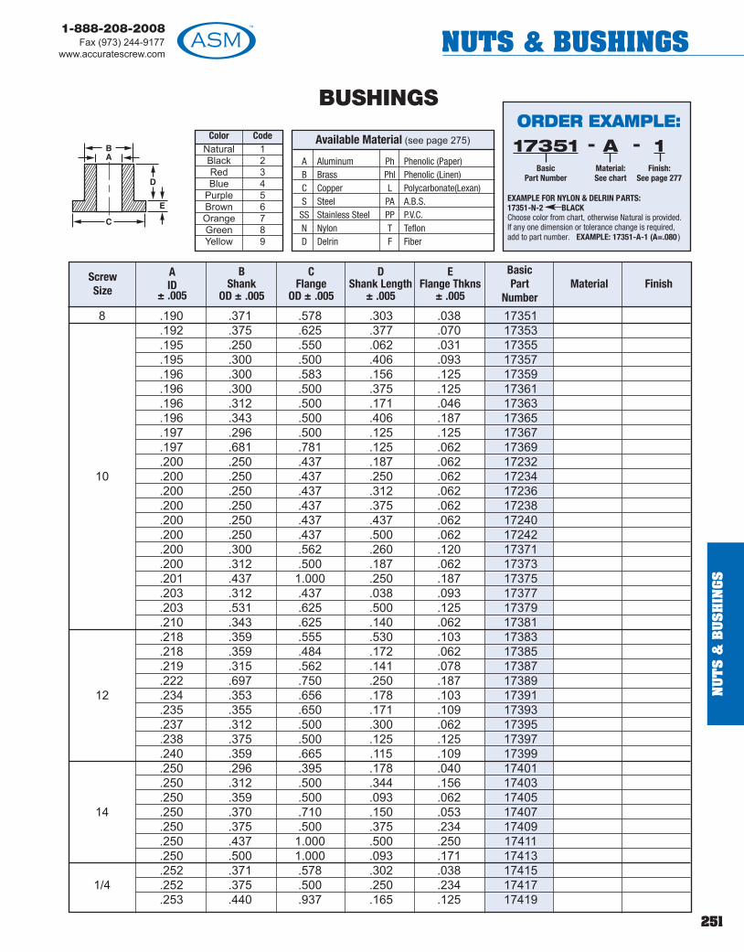
251
1-888-208-2008Fax (973) 244-9177
www.accuratescrew.com NUTS & BUSHINGS
Available Material (see page 275)BA
C
D
E
A Aluminum Ph Phenolic (Paper)B Brass Phl Phenolic (Linen)C Copper L Polycarbonate(Lexan)S Steel PA A.B.S.
SS Stainless Steel PP P.V.C.N Nylon T TeflonD Delrin F Fiber
8 .190 .371 .578 .303 .038 17351.192 .375 .625 .377 .070 17353.195 .250 .550 .062 .031 17355.195 .300 .500 .406 .093 17357.196 .300 .583 .156 .125 17359.196 .300 .500 .375 .125 17361.196 .312 .500 .171 .046 17363.196 .343 .500 .406 .187 17365.197 .296 .500 .125 .125 17367.197 .681 .781 .125 .062 17369.200 .250 .437 .187 .062 17232
10 .200 .250 .437 .250 .062 17234.200 .250 .437 .312 .062 17236.200 .250 .437 .375 .062 17238.200 .250 .437 .437 .062 17240.200 .250 .437 .500 .062 17242.200 .300 .562 .260 .120 17371.200 .312 .500 .187 .062 17373.201 .437 1.000 .250 .187 17375.203 .312 .437 .038 .093 17377.203 .531 .625 .500 .125 17379.210 .343 .625 .140 .062 17381.218 .359 .555 .530 .103 17383.218 .359 .484 .172 .062 17385.219 .315 .562 .141 .078 17387.222 .697 .750 .250 .187 17389
12 .234 .353 .656 .178 .103 17391.235 .355 .650 .171 .109 17393.237 .312 .500 .300 .062 17395.238 .375 .500 .125 .125 17397.240 .359 .665 .115 .109 17399.250 .296 .395 .178 .040 17401.250 .312 .500 .344 .156 17403.250 .359 .500 .093 .062 17405
14 .250 .370 .710 .150 .053 17407.250 .375 .500 .375 .234 17409.250 .437 1.000 .500 .250 17411.250 .500 1.000 .093 .171 17413.252 .371 .578 .302 .038 17415
1/4 .252 .375 .500 .250 .234 17417.253 .440 .937 .165 .125 17419
Color CodeNatural 1Black 2Red 3Blue 4
Purple 5Brown 6Orange 7Green 8Yellow 9
BUSHINGS
Screw Size
A ID
± .005
B Shank
OD ± .005
CFlange
OD ± .005
DShank Length
± .005
EFlange Thkns
± .005
BasicPart
Number Material Finish
ORDER EXAMPLE:
EXAMPLE FOR NYLON & DELRIN PARTS:17351-N-2 BLACKChoose color from chart, otherwise Natural is provided.If any one dimension or tolerance change is required,add to part number. EXAMPLE: 17351-A-1 (A=.080)
17351Basic
Part Number
1Finish:
See page 277
-AMaterial:See chart
-
NU
TS
&B
US
HIN
GS

252
1-888-208-2008Fax (973) 244-9177www.accuratescrew.comNUTS & BUSHINGS
NU
TS
&B
US
HIN
GS
Available Material (see page 275)BA
C
D
E
A Aluminum Ph Phenolic (Paper)B Brass Phl Phenolic (Linen)C Copper L Polycarbonate(Lexan)S Steel PA A.B.S.
SS Stainless Steel PP P.V.C.N Nylon T TeflonD Delrin F Fiber
.255 .311 .437 .072 .062 17421
.255 .312 .625 .203 .031 17423
.255 .320 .625 .109 .031 17425
.255 .370 1.250 .062 .062 17427
.255 .375 .635 .212 .062 17429
.255 .377 .500 .687 .062 17431
.255 .386 .718 .140 .156 17433
.255 .490 .750 .110 .090 17435
.256 .375 .750 .682 .062 17437
.256 .380 .500 .437 .062 17439
.258 .317 .562 .313 .062 17441
.260 .312 .500 .187 .062 17244
.260 .312 .500 .250 .062 17246
.260 .312 .500 .312 .062 17248
.260 .312 .500 .375 .062 17250
.260 .312 .500 .437 .062 17252
.260 .312 .500 .500 .062 172541/4 .260 .348 .562 .518 .031 17443
.260 .363 .500 .438 .062 17445
.260 .372 .500 .125 .125 17447
.260 .443 .562 .250 .062 17449
.260 .609 .750 .050 .125 17451
.263 .375 .500 .375 .062 17453
.265 .339 .750 .188 .062 17455
.265 .375 .625 .140 .140 17457
.265 .377 .500 .687 .062 17459
.266 .359 .625 .171 .250 17461
.273 .375 .500 .710 .040 17463
.280 .615 1.000 .625 .125 17465
.281 .380 .500 .125 .125 17467
.281 .500 .875 .500 .250 17469
.296 .370 .609 .187 .109 17471
.310 .370 .500 .225 .035 17256
.310 .455 .560 .085 .060 17258
.310 .355 .458 .288 .040 17473
.312 .365 .615 .130 .035 17475
.312 .412 .562 1.312 .050 17477.312 .500 .796 .782 .218 174795/16 .312 .800 .980 1.375 .187 17481
.315 .365 .562 .281 .062 17483
.317 .500 1.281 .125 .125 17485
Color CodeNatural 1Black 2Red 3Blue 4
Purple 5Brown 6Orange 7Green 8Yellow 9
BUSHINGS
Screw Size
A ID
± .005
B Shank
OD ± .005
CFlange
OD ± .005
DShank Length
± .005
EFlange Thkns
± .005
BasicPart
Number Material Finish
ORDER EXAMPLE:
EXAMPLE FOR NYLON & DELRIN PARTS:17421-N-2 BLACKChoose color from chart, otherwise Natural is provided.If any one dimension or tolerance change is required,add to part number. EXAMPLE: 17421-A-1 (A=.080)
17421Basic
Part Number
1Finish:
See page 277
-AMaterial:See chart
-

253
1-888-208-2008Fax (973) 244-9177
www.accuratescrew.com NUTS & BUSHINGS
Available Material (see page 275)BA
C
D
E
A Aluminum Ph Phenolic (Paper)B Brass Phl Phenolic (Linen)C Copper L Polycarbonate(Lexan)S Steel PA A.B.S.
SS Stainless Steel PP P.V.C.N Nylon T TeflonD Delrin F Fiber
.318 .437 .625 .500 .062 17487
.318 .437 .625 .503 .075 17489
.390 .320 .750 .406 .125 17491
.320 .437 .625 .250 .062 17493
.321 .470 .625 .312 .062 17495
.323 .370 .437 .062 .050 17497
.323 .370 .437 .137 .050 17499
.325 .437 .625 .531 .093 17501
.332 .443 .625 .750 .093 17503
.332 .450 .750 .125 .062 17505
.335 .617 .870 .490 .130 17260
.337 .462 .625 .562 .062 17507
.350 .375 .500 .343 .265 17509
.365 .685 1.238 .185 .310 17262
.370 .906 1.000 .375 .062 17511
.375 .500 .555 .100 .060 17264
.375 .430 .500 .220 .030 172665/16 .375 .493 .755 .030 .125 17268
.375 .490 .755 1.010 .130 17270
.375 .490 .995 .050 .175 17272
.375 .430 .695 .375 .062 17513
.375 .437 .625 .062 .031 17515
.375 .468 .687 .093 .078 17517
.375 .468 .687 .188 .062 17519
.375 .496 .750 .242 .070 17521
.375 .500 .625 .060 .133 17523
.375 .500 .625 .133 .060 17525
.375 .500 .625 .253 .062 17527
.375 .500 .750 .156 .312 17529
.375 .500 .750 .438 .062 17531
.375 .500 .750 .190 .065 17533
.375 .500 1.125 .190 .500 17535
.375 .500 .745 .750 .062 17537
.375 .500 .734 .625 .312 17539
.375 .500 .734 .625 .312 17541
.380 .500 .750 .296 .078 17543
.380 .500 .625 .515 .031 17545
.380 .525 .765 1.218 .218 175473/8 .380 .560 .750 .562 .250 17549
.380 .575 .625 .250 .062 17551
.380 .625 1.125 .250 .125 17553
Color CodeNatural 1Black 2Red 3Blue 4
Purple 5Brown 6Orange 7Green 8Yellow 9
BUSHINGS
Screw Size
A ID
± .005
B Shank
OD ± .005
CFlange
OD ± .005
DShank Length
± .005
EFlange Thkns
± .005
BasicPart
Number Material Finish
ORDER EXAMPLE:
EXAMPLE FOR NYLON & DELRIN PARTS:17487-N-2 BLACKChoose color from chart, otherwise Natural is provided.If any one dimension or tolerance change is required,add to part number. EXAMPLE: 17487-A-1 (A=.080)
17487Basic
Part Number
1Finish:
See page 277
-AMaterial:See chart
-
NU
TS
&B
US
HIN
GS

254
1-888-208-2008Fax (973) 244-9177www.accuratescrew.comNUTS & BUSHINGS
NU
TS
&B
US
HIN
GS
Available Material (see page 275)BA
C
D
E
A Aluminum Ph Phenolic (Paper)B Brass Phl Phenolic (Linen)C Copper L Polycarbonate(Lexan)S Steel PA A.B.S.
SS Stainless Steel PP P.V.C.N Nylon T TeflonD Delrin F Fiber
.382 .500 1.000 .500 .062 17555
.382 .531 .656 .671 .109 17557
.385 .500 .750 .065 .185 17274
.385 .505 .625 .562 .187 17559
.385 .570 .750 .539 .086 17561
.385 .625 .750 .500 .093 17563
.390 .515 .640 .750 .062 17565
.392 .510 .637 .309 .062 175673/8 .400 .500 .750 .090 .130 17276
.406 .690 .750 .312 .125 17569
.415 .560 .750 .550 .080 17278
.415 .625 .703 2.000 .062 17571
.420 .560 .615 .315 .375 17280
.422 .750 .984 .500 .125 17573
.430 .500 .750 .036 .187 17282
.434 .747 .993 .115 .135 17575
.442 .630 1.275 .750 .187 17577
.442 .630 1.250 1.250 .437 17579
.447 .625 .750 .125 .062 17581
.450 .625 1.275 .740 .125 17583
.453 .520 .625 .156 .046 175857/16 .453 .627 .750 .500 .093 17587
.470 .531 .937 .062 .087 17589
.470 .531 .937 .190 .084 17591
.470 .531 .937 .468 .087 17593
.472 .575 .625 .257 .062 17595
.484 .531 .625 .110 .036 17597
.500 .620 .875 .190 .065 17284
.500 .906 1.000 .375 .062 17599
.505 .690 .810 .370 .130 17286
.505 .690 .810 .430 .065 17288
.506 .628 .750 1.380 .060 17601
.508 .578 .750 .343 .031 17603
.510 .625 .875 .375 .125 176051/2 .515 .637 .750 .187 .250 17607
.520 .625 .796 .359 .062 17609
.522 .630 .750 .187 .062 17611
.531 .747 .993 .240 .135 17613
.565 .665 .750 .647 .040 17615
.578 .687 .921 .735 .046 17617
.593 .785 .900 .375 .125 17619
Color CodeNatural 1Black 2Red 3Blue 4
Purple 5Brown 6Orange 7Green 8Yellow 9
BUSHINGS
Screw Size
A ID
± .005
B Shank
OD ± .005
CFlange
OD ± .005
DShank Length
± .005
EFlange Thkns
± .005
BasicPart
Number Material Finish
ORDER EXAMPLE:
EXAMPLE FOR NYLON & DELRIN PARTS:17555-N-2 BLACKChoose color from chart, otherwise Natural is provided.If any one dimension or tolerance change is required,add to part number. EXAMPLE: 17555-A-1 (A=.080)
17555Basic
Part Number
1Finish:
See page 277
-AMaterial:See chart
-

255
1-888-208-2008Fax (973) 244-9177
www.accuratescrew.com MISC. COMPONENTS
MIS
C. C
OM
PO
NE
NT
S
Nom. Std.SizeIn.
L
Screw driver slot available(see order example)
Class 1A Rolled Thread
THREADED STUD18/8 Stainless Steel
THREADED STUD316 Stainless Steel
4-40 9005606-32 9005628-32 90056410-24 90056610-32 90056812-24 9005701/4-20 9005721/4-28 9005745/16-18 9005765/16-24 9005783/8-16 9005803/8-24 9005827/16-14 9005841/2-13 9005861/2-20 9005889/16-12 9005905/8-11 9005923/4-10 9005947/8-9 9005961-8 900598
1-1/8-7 9006001-1/4-7 900602
ThreadSize
Basic PartNumber
L Length(1/2 minimum) Finish
1/4-20 9006045/16-18 9006063/8-16 9006081/2-13 9006105/8-11 9006123/4-10 9006147/8-9 9006161-8 900618
ORDER EXAMPLE:- -900560
Basic Part Number
.500Length:
Fill in your length
12Finish:
See page 277
Screw Driver Slot is available (.060 X .060), one end only, 8-32 thread and larger,add SDS to part number. EXAMPLE: 900560-.500-SDS-12Self-Locking Device is available (one sided only), add SLD (Pellet Type) orSLDS (Strip Type) to part number.EXAMPLE: 900560-.500-SLD or SLDS-12
Tolerance on Length - In.
To 5/16 ±0.03 ±0.06Over 5/16 to 3/4 ±0.06 ±0.12Over 3/4 to 1-1/4 ±0.12 ±0.19Over 1-1/4 ±0.25 ±0.25
For Lengths6 In. andShorter
For LengthsOver 6 In.
Nom. Std.SizeIn.
L
Screw driver slot available(see order example)
Class 1A Rolled Thread
ORDER EXAMPLE:- -900604
Basic Part Number
.500Length:
Fill in your length
12Finish:
See page 277
Screw Driver Slot is available (.060 X .060), one end only, 8-32 thread and larger,add SDS to part number. EXAMPLE: 900604-.500-SDS-12Self-Locking Device is available (one sided only), add SLD (Pellet Type) orSLDS (Strip Type) to part number.EXAMPLE: 900604-.500-SLD or SLDS-12
Tolerance on Length - In.
To 5/16 ±0.03 ±0.06Over 5/16 to 3/4 ±0.06 ±0.12Over 3/4 to 1-1/4 ±0.12 ±0.19Over 1-1/4 ±0.25 ±0.25
For Lengths6 In. andShorter
For LengthsOver 6 In.
Thread Size Basic PartNumber
L Length(1/2 minimum)
Finish

256
1-888-208-2008Fax (973) 244-9177www.accuratescrew.comMISC. COMPONENTS
MIS
C. C
OM
PO
NE
NT
S
THREADED STUDLow Carbon Steel (1008-1020)
6-32 9006208-32 90062210-24 90062410-32 9006261/4-20 9006281/4-28 9006305/16-18 9006325/16-24 9006343/8-16 9006363/8-24 9006387/16-14 9006407/16-20 9006421/2-13 9006441/2-20 9006469/16-12 9006489/16-18 9006505/8-11 9006525/8-18 9006543/4-10 9006563/4-16 9006587/8-9 9006607/8-14 900662
1-8 9006641-14 900666
1-1/8-7 9006681-1/4-7 9006701-3/8-6 9006721-1/2-6 9006741-3/4-5 9006762-4-1/2 900678
Nom. Std.SizeIn.
L
Screw driver slot available(see order example)
Class 1A Rolled Thread
ORDER EXAMPLE:- -900620
Basic Part Number
.500Length:
Fill in your length
7Finish:
See page 277
Screw Driver Slot is available (.060 X .060), one end only, 8-32 thread and larger,add SDS to part number. EXAMPLE: 900620-.500-SDS-7Self-Locking Device is available (one sided only), add SLD (Pellet Type) orSLDS (Strip Type) to part number.EXAMPLE: 900620-.500-SLD or SLDS-7
Tolerance on Length - In.
To 5/16 ±0.03 ±0.06Over 5/16 to 3/4 ±0.06 ±0.12Over 3/4 to 1-1/4 ±0.12 ±0.19Over 1-1/4 ±0.25 ±0.25
For Lengths6 In. andShorter
For LengthsOver 6 In.
Thread Size Basic PartNumber
L Length(1/2 minimum)
Finish
! TECHTIPYou can view or print ourISO certification atwww.accuratescrew.com
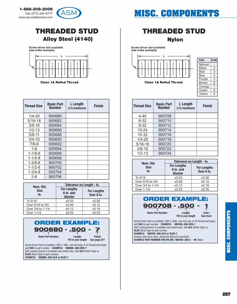
257
1-888-208-2008Fax (973) 244-9177
www.accuratescrew.com MISC. COMPONENTS
MIS
C. C
OM
PO
NE
NT
S
THREADED STUDAlloy Steel (4140)
THREADED STUDNylon
1/4-20 9006805/16-18 9006823/8-16 9006841/2-13 9006865/8-11 9006883/4-10 9006907/8-9 9006921-8 900694
1-1/8-8 9006961-1/4-8 9006981-3/8-8 9007001-1/2-8 9007021-3/4-8 900704
2-8 900706
Nom. Std.SizeIn.
L
Screw driver slot available(see order example)
Class 1A Rolled Thread
ORDER EXAMPLE:- -900680
Basic Part Number
.500Length:
Fill in your length
7Finish:
See page 277
Screw Driver Slot is available (.060 X .060), one end only, 8-32 thread and larger,add SDS to part number. EXAMPLE: 900680-.500-SDS-7Self-Locking Device is available (one sided only), add SLD (Pellet Type) orSLDS (Strip Type) to part number.EXAMPLE: 900680-.500-SLD or SLDS-7
Tolerance on Length - In.
To 5/16 ±0.03 ±0.06Over 5/16 to 3/4 ±0.06 ±0.12Over 3/4 to 1-1/4 ±0.12 ±0.19Over 1-1/4 ±0.25 ±0.25
For Lengths6 In. andShorter
For LengthsOver 6 In.
Thread Size Basic PartNumber
L Length(1/2 minimum)
Finish
4-40 9007086-32 9007108-32 90071210-24 90071410-32 9007161/4-20 9007185/16-18 9007203/8-16 9007221/2-13 900724
Nom. Std.SizeIn.
ORDER EXAMPLE:- -900708
Basic Part Number
.500Length:
Fill in your length
1Color:
See chart
Screw Driver Slot is available (.060 X .060), one end only, 8-32 thread and larger,add SDS to part number. EXAMPLE: 900708-.500-SDS-1Self-Locking Device is available (one sided only), add SLD (Pellet Type) orSLDS (Strip Type) to part number.EXAMPLE: 900708-.500-SLD or SLDS-1Choose color from chart, otherwise Natural is provided.EXAMPLE PART NUMBER FOR NYLON: 900708-.500-2 Black
Tolerance on Length - In.
To 5/16 ±0.03 ±0.06Over 5/16 to 3/4 ±0.06 ±0.12Over 3/4 to 1-1/4 ±0.12 ±0.19Over 1-1/4 ±0.25 ±0.25
For Lengths6 In. andShorter
For LengthsOver 6 In.
Thread Size Basic PartNumber
L Length(1/2 minimum)
Finish
L
Screw driver slot available(see order example)
Class 1A Rolled Thread
Natural 1Black 2Red 3Blue 4Purple 5Brown 6Orange 7Green 8Yellow 9
Color Code

258
1-888-208-2008Fax (973) 244-9177www.accuratescrew.comMISC. COMPONENTS
MIS
C. C
OM
PO
NE
NT
S
THREADED STUDAluminum (2011)
6-32 9005008-32 90050210-24 90050410-32 9005061/4-20 9005085/16-18 9005103/8-16 9005121/2-13 900514
ThreadSize
Basic PartNumber
L Length(1/2 minimum) Finish
4-40 9005186-32 9005208-32 90052210-24 90052410-32 90052612-24 9005281/4-20 9005301/4-28 9005325/16-18 9005345/16-24 9005363/8-16 9005383/8-24 9005407/16-14 9005421/2-13 9005441/2-20 9005465/8-11 9005485/8-18 9005503/4-10 9005527/8-9 9005541-8 900556
ThreadSize
Basic PartNumber
L Length(1/2 minimum) Finish
THREADED STUDBrass (CDA360)
Nom. Std.SizeIn.
L
Screw driver slot available(see order example)
Class 1A Rolled Thread
ORDER EXAMPLE:- -900500
Basic Part Number
.500Length:
Fill in your length
22Finish:
See page 277
Screw Driver Slot is available (.060 X .060), one end only, 8-32 thread and larger,add SDS to part number. EXAMPLE: 900500-.500-SDS-22Self-Locking Device is available (one sided only), add SLD (Pellet Type) orSLDS (Strip Type) to part number.EXAMPLE: 900500-.500-SLD or SLDS-22
Tolerance on Length - In.
To 5/16 ±0.03 ±0.06Over 5/16 to 3/4 ±0.06 ±0.12Over 3/4 to 1-1/4 ±0.12 ±0.19Over 1-1/4 ±0.25 ±0.25
For Lengths6 In. andShorter
For LengthsOver 6 In.
Nom. Std.SizeIn.
L
Screw driver slot available(see order example)
Class 1A Rolled Thread
ORDER EXAMPLE:- -900518
Basic Part Number
.500Length:
Fill in your length
7Finish:
See page 277
Screw Driver Slot is available (.060 X .060), one end only, 8-32 thread and larger,add SDS to part number. EXAMPLE: 900518-.500-SDS-7Self-Locking Device is available (one sided only), add SLD (Pellet Type) orSLDS (Strip Type) to part number.EXAMPLE: 900518-.500-SLD or SLDS-7
Tolerance on Length - In.
To 5/16 ±0.03 ±0.06Over 5/16 to 3/4 ±0.06 ±0.12Over 3/4 to 1-1/4 ±0.12 ±0.19Over 1-1/4 ±0.25 ±0.25
For Lengths6 In. andShorter
For LengthsOver 6 In.

259
1-888-208-2008Fax (973) 244-9177
www.accuratescrew.com MISC. COMPONENTS
MIS
C. C
OM
PO
NE
NT
S
Length
.250Basic Part Number
1700Material Shank Length Finish
CHASSIS FASTENERS1/4" - SQUARE
4-40Thread
Drill .098.063 Deep
.250
.125
.125 ± .003
1/4"
1/4"
.125X ± .003
6-32Thread*
Drill 5/32" (.156).093 Deep
.375
.218
.187 ± .002
5/16"
5/16"
.156X ± .003
.075
.105
.135
.165
.230
.290
RecommendedShank Length
5/16" - SQUARE
X = Length of Shank
NOTE: Standard materials. Other materials on special order .
A AluminumB BrassS Steel
SS Stainless Steel
Available Material (see page 275)ORDER EXAMPLE:- -1700
BasicPart Number
.105Shank Length:
Fill in your length
7Finish:
See page 277
BMaterial:See chart
-
ORDER EXAMPLE:- -1800
BasicPart Number
.105Shank Length:
Fill in your length
7Finish:
See page 277
*4-40 thread is available on special order , add 4-40 to the partnumber. EXAMPLE: 1800-B-.075-7 (4-40)
BMaterial:See chart
-
.075
.105
.135
.165
.230
.290
RecommendedShank Length
X = Leng h of Shank
A Aluminum
B Brass
S Steel
SS Stainless Steel
Available Material (see page 275)
Length
.375Basic Part Number
1800Material Shank Length Finish

1-888-208-2008Fax (973) 244-9177www.accuratescrew.comHANDLES
HA
ND
LES
260
8400840284041/8 84068408841084128100
5/32 841684188420842484263/16 84288430
ROUND HANDLES
1/23/411/8 1-1/4
1-1/22
3/41
5/32 1-1/41-1/2
23/47/83/16 1
1-1/8
NOTE: Where “H” dimension is 1" or smaller , thread will be minimum depth possible or minimum of 3 full threads.
A AluminumB BrassC CopperS Steel 12L14
SS Stainless Steel, Type 303
Available Material (see page 275)
Thread B Min. Depth of Thread
2-56 3/164-40 1/4
ORDER EXAMPLE:8400
BasicPart
Number
1.500Length Abetweencenters
256Thread
SSMaterial:See chart
12Finish:
See page277
----
If metric thread is required, add to part number . EXAMPLE: 8400-1.500-M2-SS-12
If a different thread depth B is required, add requirement to part number . EXAMPLE: 8400-1.500-256-SS-12 (B = 256 x 3/8)
Diameter HeightApproxRadius
BasicPart Number
Length A±1/32
Thread Material Finish
FIRM GRIP MOLDED PLASTIC COATING
ORDER EXAMPLE:8400
BasicPart
Number
4.00Length Abetweencenters
256Thread
AMaterial:See chart
1Finish:
See page277
---- FGFirm Grip:
See note below
BLColor:
See chart
--
RecommendedColors
OTHER COLORS(6 Weeks Delivery)
Black BLBlue BRed RGreen G
White WYellow YClear COrange OBrown BRPurple P ! TECH
TIPFirm grip handlesavailable in tendifferent colors.

261
1-888-208-2008Fax (973) 244-9177
www.accuratescrew.com HANDLES
ROUND HANDLES
NOTE: Where “H” dimension is 1 or smaller , thread will be minimum dep h possible or minimum of 3 full threads.
Thread B Min. Depth of Thread
2-56 3/164-40 1/46-32 9/328-32 5/1610-24 3/810-32 3/81/4-20 9/161/4-28 9/16
84323/16 8434
8436810381048105810681071/4 81088438844084428444
5/16 8110
1-1/43/16 1-1/2
21
1-1/41-1/2
22-1/21/4 2-3/4
33-1/2
44-1/4
5/16 1
ORDER EXAMPLE:8432
BasicPart
Number
1.500Length Abetweencenters
632Thread
SSMaterial:See chart
12Finish:
See page277
----
If metric thread is required, add to part number . EXAMPLE: 8432-1.500-M3-SS-12
If a different thread depth B is required, add requirement to part number . EXAMPLE: 8432-1.500-6-32-SS-12 (B = 6-32 x 3/8)
Diameter HeightApproxRadius
BasicPart Number
Length A±1/32
Thread Material Finish
A AluminumB BrassC CopperS Steel 12L14
SS Stainless Steel, Type 303
Available Material (see page 275)
FIRM GRIP MOLDED PLASTIC COATING
ORDER EXAMPLE:8432
BasicPart
Number
4.00Length Abetweencenters
256Thread
AMaterial:See chart
1Finish:
See page277
---- FGFirm Grip:
See note below
BLColor:
See chart
--
RecommendedColors
OTHER COLORS(6 Weeks Delivery)
Black BLBlue BRed RGreen G
White WYellow YClear COrange OBrown BRPurple P
HA
ND
LES
! TECHTIPASM can supplythe hardwarefor all of ourhandles.
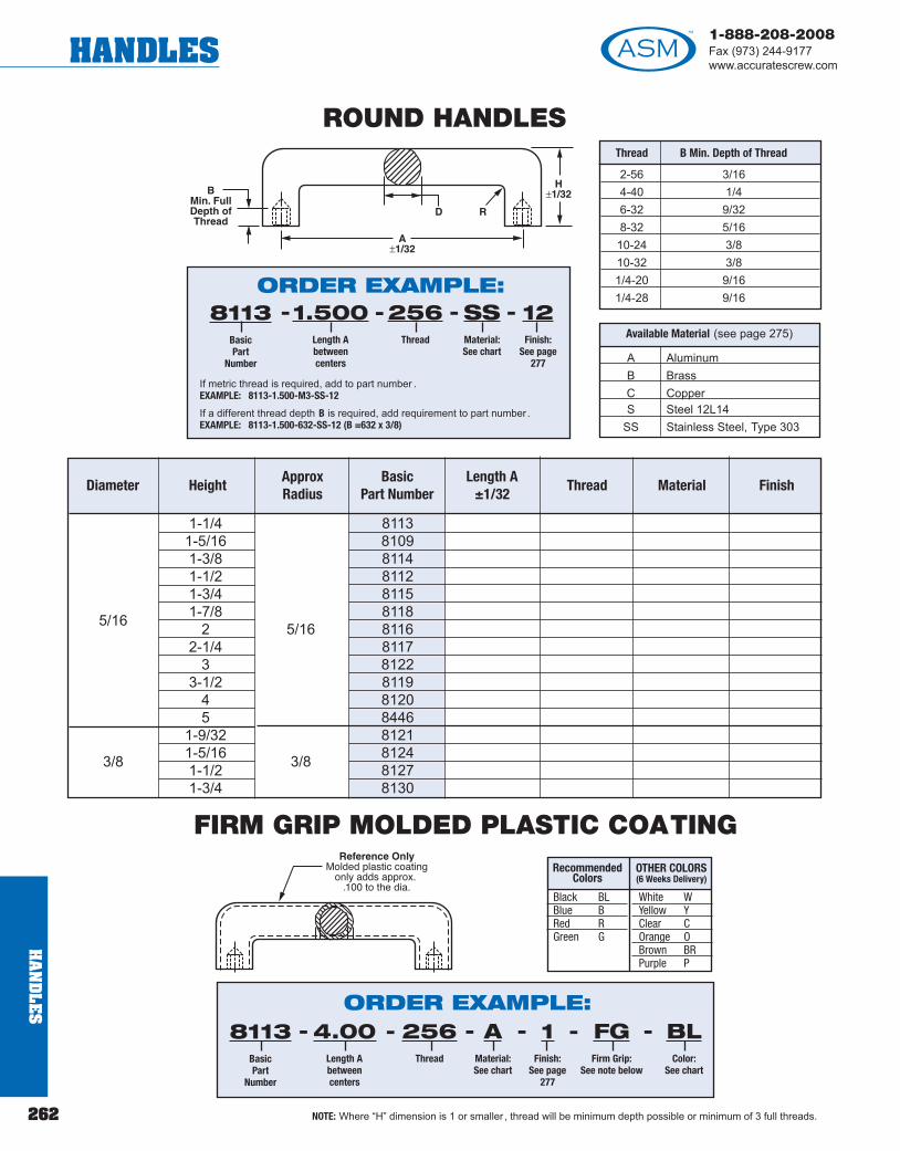
1-888-208-2008Fax (973) 244-9177www.accuratescrew.comHANDLES
262
HA
ND
LES
NOTE: Where “H” dimension is 1 or smaller , thread will be minimum depth possible or minimum of 3 full threads.
811381098114811281158118
5/16 811681178122811981208446812181243/8 81278130
ROUND HANDLES
1-1/41-5/161-3/81-1/21-3/41-7/85/16 22-1/4
33-1/2
45
1-9/321-5/163/8 1-1/21-3/4
ORDER EXAMPLE:8113
BasicPart
Number
1.500Length Abetweencenters
256Thread
SSMaterial:See chart
12Finish:
See page277
----
If metric thread is required, add to part number . EXAMPLE: 8113-1.500-M3-SS-12
If a different thread depth B is required, add requirement to part number . EXAMPLE: 8113-1.500-632-SS-12 (B =632 x 3/8)
Diameter HeightApproxRadius
BasicPart Number
Length A±1/32
Thread Material Finish
Thread B Min. Depth of Thread
2-56 3/164-40 1/46-32 9/328-32 5/1610-24 3/810-32 3/81/4-20 9/161/4-28 9/16
A AluminumB BrassC CopperS Steel 12L14
SS Stainless Steel, Type 303
Available Material (see page 275)
FIRM GRIP MOLDED PLASTIC COATING
ORDER EXAMPLE:8113
BasicPart
Number
4.00Length Abetweencenters
256Thread
AMaterial:See chart
1Finish:
See page277
---- FGFirm Grip:
See note below
BLColor:
See chart
--
RecommendedColors
OTHER COLORS(6 Weeks Delivery)
Black BLBlue BRed RGreen G
White WYellow YClear COrange OBrown BRPurple P

263
1-888-208-2008Fax (973) 244-9177
www.accuratescrew.com HANDLES
NOTE: Where “H” dimension is 1 or smaller , thread will be minimum dep h possible or minimum of 3 full threads.
8133812381253/8 8139812681288132813481358136
1/2 81378140813881428141
ROUND HANDLES
1-7/82
2-3/83/8 2-1/234
1-5/81-3/41-7/8
21/2 2-3/8
2-1/2345
ORDER EXAMPLE:8133
BasicPart
Number
1.500Length Abetweencenters
632Thread
SSMaterial:See chart
12Finish:
See page277
----
If metric thread is required, add to part number . EXAMPLE: 8133-1.500-M3-SS-12
If a different thread depth B is required, add requirement to part number . EXAMPLE: 8133-1.500-632-SS-12 (B = 6-32 x 3/8)
Diameter HeightApproxRadius
BasicPart Number
Length A±1/32
Thread Material Finish
Thread B Min. Depth of Thread
2-56 3/164-40 1/46-32 9/328-32 5/1610-24 3/810-32 3/81/4-20 9/161/4-28 9/165/16-18 9/16
A AluminumB BrassC CopperS Steel 12L14
SS Stainless Steel, Type 303
Available Material (see page 275)
FIRM GRIP MOLDED PLASTIC COATING
ORDER EXAMPLE:8133
BasicPart
Number
4.00Length Abetweencenters
256Thread
AMaterial:See chart
1Finish:
See page277
---- FGFirm Grip:
See note below
BLColor:
See chart
--
RecommendedColors
OTHER COLORS(6 Weeks Delivery)
Black BLBlue BRed RGreen G
White WYellow YClear COrange OBrown BRPurple P
HA
ND
LES

1-888-208-2008Fax (973) 244-9177www.accuratescrew.comHANDLES
264
HA
ND
LES
1 93001-9/32 9302
7/16 x 9/32 1-1/2 93041-3/4 9306
2 93081 9310
1-9/32 93121-1/2 93141-3/4 9316
5/8 x 9/32 2 93182-1/4 93202-1/2 9322
3 93244 9326
Oval Height FinishMaterialThreadSee chart for
recommendedLength A ± 1/32
BasicPart
Number
NOTE: Where H dimension is 1" or smaller , thread will be maximum depth possible or minimum of 3 full threads.
RecommendedLength A ±1/32
2.000 4.5622.250 5.0002.500 6.0003.000 6.4373.500 7.0004.000 8.0004.250 9.0004.500 12.000
A AluminumSS Stainless Steel
Available Material (see page 275)
Thread B Min. Depth of Thread
2-56 3/164-40 1/46-32 9/328-32 5/1610-32 3/8
OVAL HANDLES
ORDER EXAMPLE:9300
BasicPart
Number
2.00Length Abetweencenters
10-32Thread
SSMaterial:See chart
12Finish:
See page277
----
If metric thread is required, add to part number . EXAMPLE: 9300-1.500-M3-SS-12
If a different thread depth B is required, add requirement to part number . EXAMPLE: 9300-1.500-632-SS-12 (B = 6-32 x 3/8)
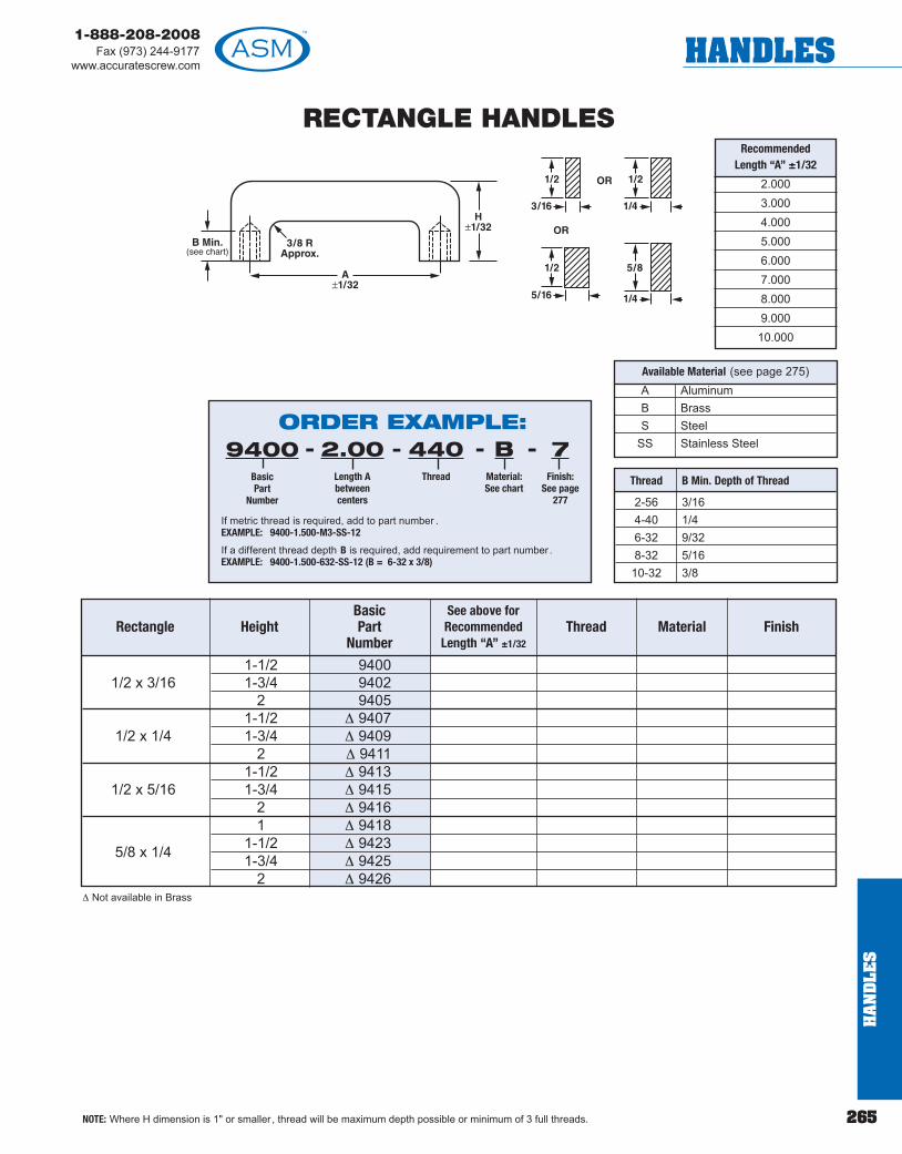
265
1-888-208-2008Fax (973) 244-9177
www.accuratescrew.com HANDLES
RECTANGLE HANDLES
NOTE: Where H dimension is 1" or smaller , thread will be maximum depth possible or minimum of 3 full threads.
RecommendedLength “A” ±1/32
2.0003.0004.0005.0006.0007.0008.0009.00010.000
A AluminumB BrassS Steel
SS Stainless Steel
Available Material (see page 275)
Thread B Min. Depth of Thread
2-56 3/164-40 1/46-32 9/328-32 5/1610-32 3/8
1-1/2 94001/2 x 3/16 1-3/4 9402
2 94051-1/2 Δ 9407
1/2 x 1/4 1-3/4 Δ 94092 Δ 9411
1-1/2 Δ 94131/2 x 5/16 1-3/4 Δ 9415
2 Δ 94161 Δ 9418
1-1/2 Δ 94235/8 x 1/4 1-3/4 Δ 94252 Δ 9426
Rectangle Height FinishMaterialThreadSee above forRecommended
Length “A” ±1/32
BasicPart
Number
Δ Not available in Brass
ORDER EXAMPLE:9400
BasicPart
Number
2.00Length Abetweencenters
440Thread
BMaterial:See chart
7Finish:
See page277
----
If metric thread is required, add to part number . EXAMPLE: 9400-1.500-M3-SS-12
If a different thread depth B is required, add requirement to part number . EXAMPLE: 9400-1.500-632-SS-12 (B = 6-32 x 3/8)
HA
ND
LES

1-888-208-2008Fax (973) 244-9177www.accuratescrew.comHANDLES
266
SIDE MOUNTED ROUND HANDLE
114032 2.56 1.40114034 5/16 5/16 3.06 1.90 .156 .219114036 3.56 2.40114038 2.56 1.40114040 3/8 3/8 3.06 1.90 .204 .187 .282 .41114042 3.56 2.40114044 2.56 1.40114046 1/2 3/8 3.06 1.90 .250 .407114048 3.56 2.40
A AluminumB BrassS Steel
SS Stainless Steel
Available Material (see page 275)
ORDER EXAMPLE:114032
BasicPart
Number
1.000Length Abetweencenters
AMaterial:See chart
22Finish:
See page277
---
Any one dimension or tolerance may be changed by adding to part number .EXAMPLE: 114032-1.000-A-22MOD (X=.625)
BasicPart
Number
D Diameter Radius
H+ .020- .040
H1± .020
F ± .005
G ± .010
C ± .010
X ± .010
A ± .010 Material Finish
HA
ND
LES
! TECH TIPNot sure whether the part you selected will fit in yourapplication? Download a 3D CAD model of the part (inthe format of your choice) from www.accuratescrew.comand find out!

267
1-888-208-2008Fax (973) 244-9177
www.accuratescrew.com HANDLES
OFFSET INTERNAL THREAD HANDLESSee pages 260-263 for complete information.
3/16 Round
1/4 Round
5/16 Round
3/8 Round
A
9/16±3/32
5/16±1/16
ORDER EXAMPLE:8428
BasicPart
Number
2.00Length Abetweencenters
440Thread
SSMaterial:See chart
FOffset
---- 1Finish:
See page277
-
NOTE: H-length minimum of 1.00
HA
ND
LES

1-888-208-2008Fax (973) 244-9177www.accuratescrew.comHANDLES
268
ROUND EXTERNAL THREADED HANDLES
A AluminumB BrassC CopperS Steel
SS Stainless Steel
Available Material (see page 275)
Threaded ferrule and nut supplied with above handles.
ORDER EXAMPLE:9100
BasicPart
Number
3.000Fill in
required length
SSMaterial:See chart
12Finish:
See page277
---
L = min. 2.00H
AN
DLE
S ! TECH TIPWe can bend our handlesup to 1/2" OD.

269
1-888-208-2008Fax (973) 244-9177
www.accuratescrew.com HANDLES
ROUND EXTERNAL THREADED HANDLES WITH SHOULDERS
9200 19202 3/16 1-1/2 3/169204 29206 19208 1/4 1-1/2 1/49210 29212 1-13/169214 5/16 2 5/169216 2-1/49218 29220 3/8 2-1/2 3/89222 39224 2-1/29226 39228 1/2 3-1/2 1/2
9230 4
Part No. Diameter Height Approx.Radius
Length A± .015
Thread Material Finish
*Minimum center-to-center “L” 2.00Nuts and washers not supplied.
A AluminumB BrassC CopperS Steel
SS Stainless Steel
Available Material (see page 275)
3/16 4-40 or 6-32
1/4 8-32 or 10-32
5/16 10-32 or 1/4-20
3/8 10-32, 1/4-20, or5/16-18
1/2 10-32, 1/4-20, 5/16-18or 3/8-24
Dia. Recommended Thread
ORDER EXAMPLE:9200
BasicPart
Number
2.00Length “A”minimum
center-to-center“L” 2.00
440Thread
SSMaterial:See chart
12Finish:
See page277
----
HA
ND
LES

1-888-208-2008Fax (973) 244-9177www.accuratescrew.comHANDLES
270
HA
ND
LES
FERRULES
For 1/4-20 ThreadPart Number 8202A
For 8-32 ThreadPart Number 8202
For 5/16" Diameter Handles For 10-32 Thread
Part Number 8206For 1/4-20 Thread
Part Number 8206AFor 5/16-18 Thread
Part Number 8206B
For 10-32 ThreadPart Number 8210
For 1/4-20 ThreadPart Number 8208A
For 10-32 ThreadPart Number 8208
For 1/2" Diameter HandlesFor 1/4-20 Thread
Part Number 8209For 3/8-24 Thread
Part Number 8209AFor 5/16-18 Thread
Part Number 8209BFor 10-32 Thread
Part Number 8209C
For 3/8" Diameter Handles
A Aluminum
B Brass
C Copper
SS Stainless Steel
Available Material (see page 275)
For 5/32" Diameter Handles For 2-56 Thread
Part Number 8200
For 3/16" Diameter Handles For 4-40 Thread
Part Number 8201
For 1/4" Diameter HandlesFor 10-32 Thread
Part Number 8204
ORDER EXAMPLE:8200
BasicPart
Number
SSMaterial:See chart
12Finish:
See page277
--
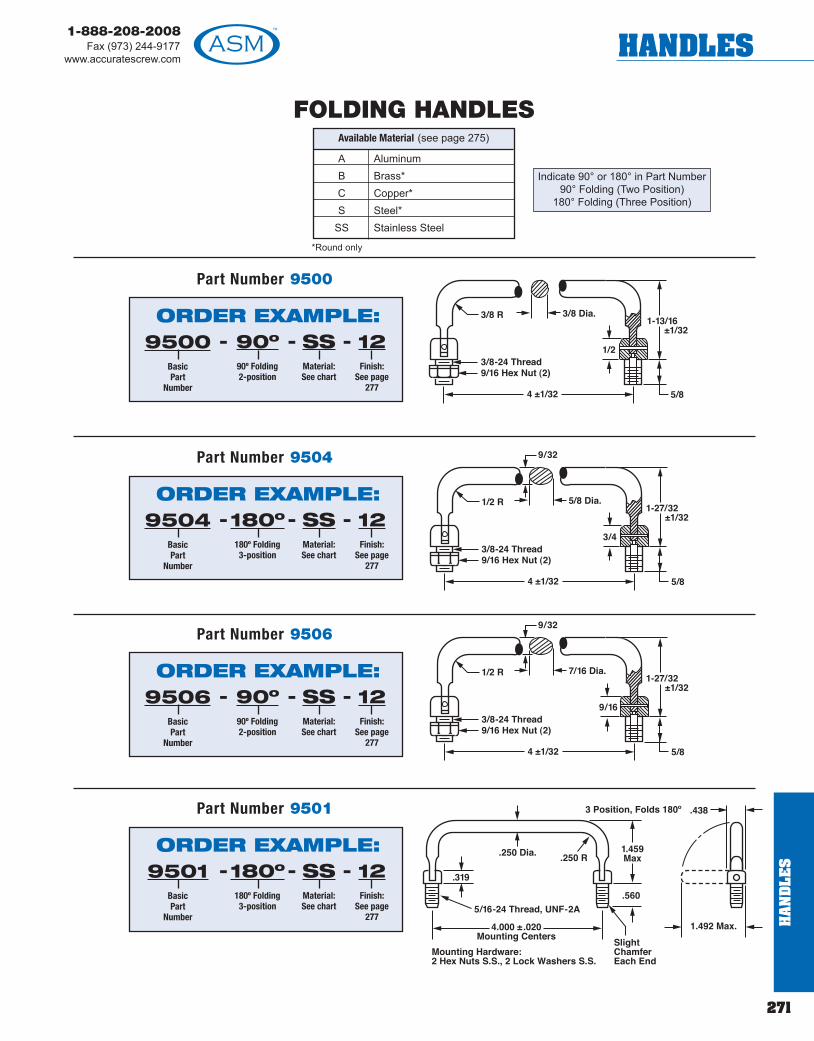
271
1-888-208-2008Fax (973) 244-9177
www.accuratescrew.com HANDLES
Indicate 90° or 180° in Part Number90° Folding (Two Position)
180° Folding (Three Position)
Part Number 9500
FOLDING HANDLES
ORDER EXAMPLE:9500
BasicPart
Number
90º90º Folding2-position
SSMaterial:See chart
12Finish:
See page277
---
A AluminumB Brass*C Copper*S Steel*
SS Stainless Steel
Available Material (see page 275)
*Round only
Part Number 9504
ORDER EXAMPLE:9504
BasicPart
Number
180º180º Folding3-position
SSMaterial:See chart
12Finish:
See page277
---
Part Number 9506
ORDER EXAMPLE:9506
BasicPart
Number
90º90º Folding2-position
SSMaterial:See chart
12Finish:
See page277
---
Part Number 9501
ORDER EXAMPLE:9501
BasicPart
Number
180º180º Folding3-position
SSMaterial:See chart
12Finish:
See page277
---
HA
ND
LES
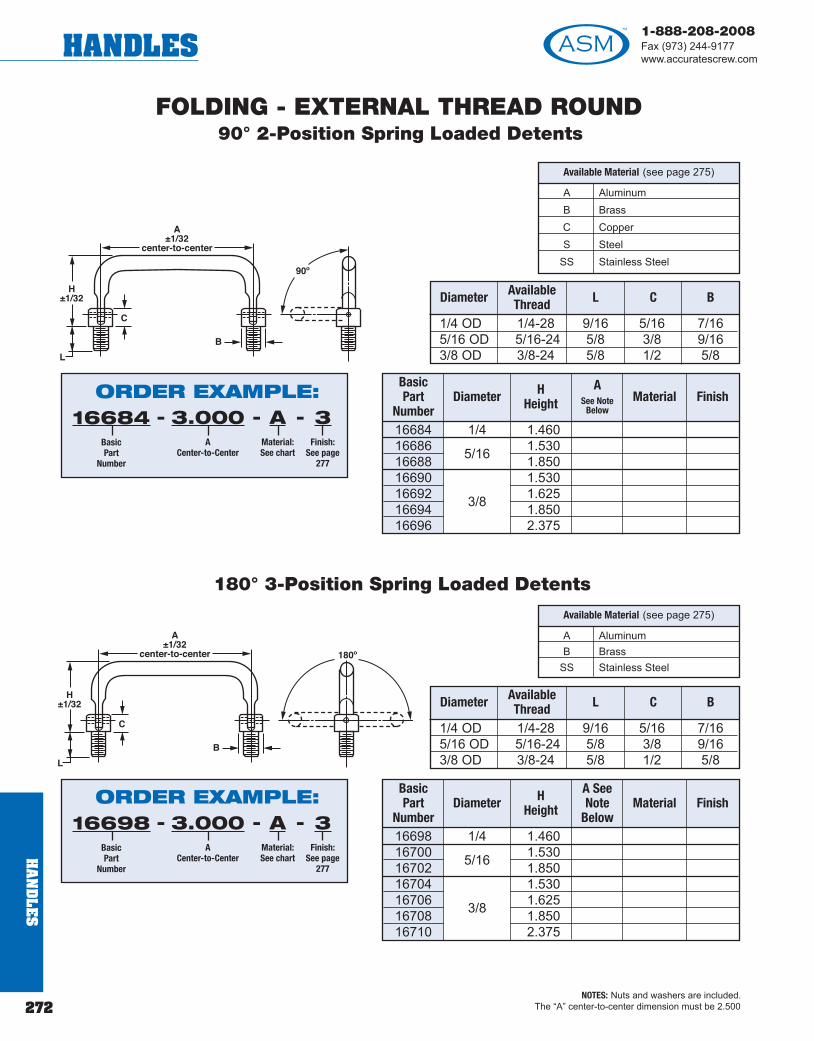
1-888-208-2008Fax (973) 244-9177www.accuratescrew.comHANDLES
272
HA
ND
LES
FOLDING - EXTERNAL THREAD ROUND90° 2-Position Spring Loaded Detents
180° 3-Position Spring Loaded Detents
BasicPart
Number
HHeightDiameter
16684 1/4 1.46016686 1.53016688 5/16 1.85016690 1.53016692 1.62516694 3/8 1.85016696 2.375
NOTES: Nuts and washers are included.The “A” center-to-center dimension must be 2.500
AvailableThread LDiameter
1/4 OD 1/4-28 9/16 5/16 7/165/16 OD 5/16-24 5/8 3/8 9/163/8 OD 3/8-24 5/8 1/2 5/8
C B
A See Note
BelowFinishMaterial
A AluminumB Brass
SS Stainless Steel
Available Material (see page 275)
AvailableThread LDiameter
1/4 OD 1/4-28 9/16 5/16 7/165/16 OD 5/16-24 5/8 3/8 9/163/8 OD 3/8-24 5/8 1/2 5/8
C B
BasicPart
Number
HHeightDiameter
16698 1/4 1.46016700 1.53016702 5/16 1.85016704 1.53016706 1.62516708 3/8 1.85016710 2.375
A SeeNote
BelowFinishMaterial
ORDER EXAMPLE:16684
BasicPart
Number
3.000A
Center-to-Center
AMaterial:See chart
3Finish:
See page277
---
ORDER EXAMPLE:16698
BasicPart
Number
3.000A
Center-to-Center
AMaterial:See chart
3Finish:
See page277
---
A AluminumB BrassC CopperS Steel
SS Stainless Steel
Available Material (see page 275)
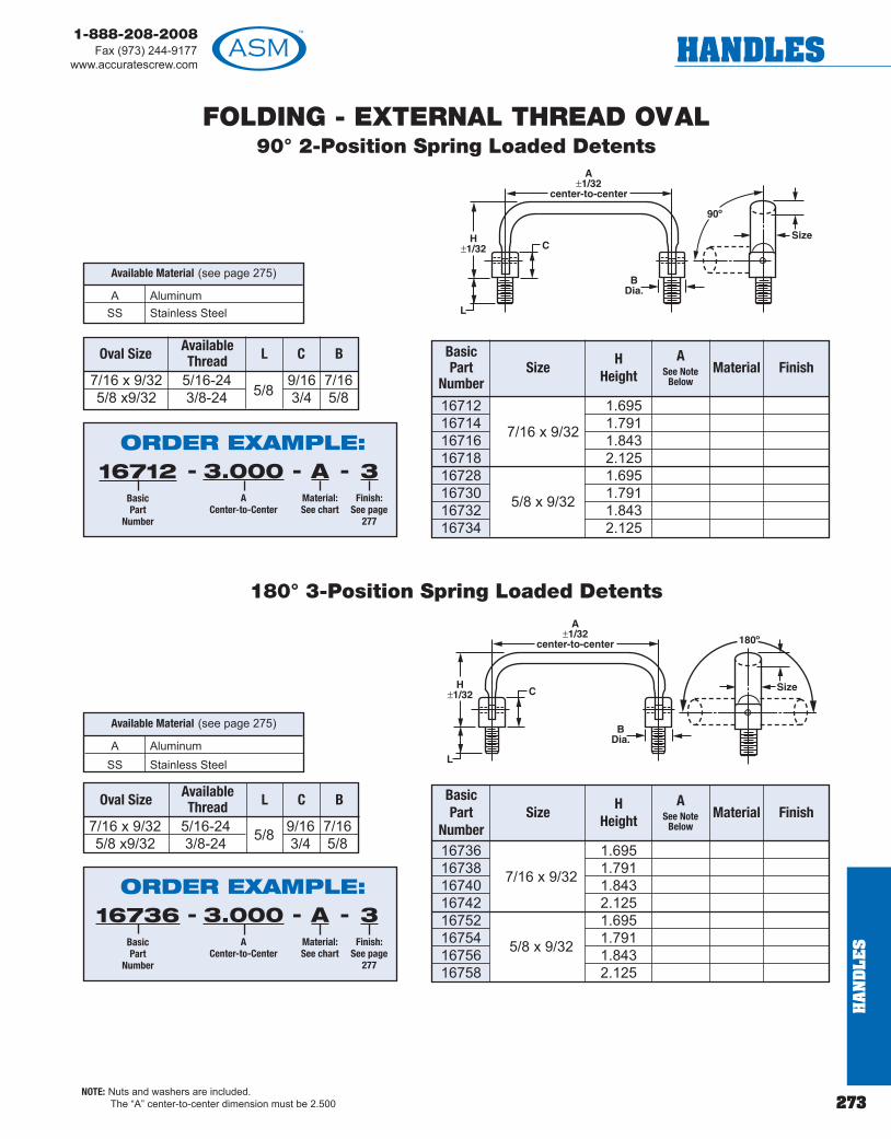
273
1-888-208-2008Fax (973) 244-9177
www.accuratescrew.com HANDLES
FOLDING - EXTERNAL THREAD OVAL90° 2-Position Spring Loaded Detents
7/16 x 9/32 5/16-245/8
9/16 7/165/8 x9/32 3/8-24 3/4 5/8
180° 3-Position Spring Loaded Detents
Oval Size LAvailableThread BC
NOTE: Nuts and washers are included. The “A” center-to-center dimension must be 2.500
BasicPart
Number
HHeight
Size
16712 1.69516714 1.79116716 7/16 x 9/32 1.84316718 2.12516728 1.69516730 1.79116732 5/8 x 9/32 1.84316734 2.125
A See Note
BelowFinishMaterial
A AluminumSS Stainless Steel
Available Material (see page 275)
A AluminumSS Stainless Steel
Available Material (see page 275)
7/16 x 9/32 5/16-24 9/16 7/165/8 x9/32 3/8-24 5/8 3/4 5/8
Oval Size LAvailableThread BC Basic
PartNumber
HHeight
Size
16736 1.69516738 1.79116740 7/16 x 9/32 1.84316742 2.12516752 1.69516754 1.79116756 5/8 x 9/32 1.84316758 2.125
A See Note
BelowFinishMaterial
ORDER EXAMPLE:16712
BasicPart
Number
3.000A
Center-to-Center
AMaterial:See chart
3Finish:
See page277
---
ORDER EXAMPLE:16736
BasicPart
Number
3.000A
Center-to-Center
AMaterial:See chart
3Finish:
See page277
---
HA
ND
LES
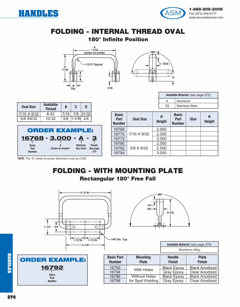
1-888-208-2008Fax (973) 244-9177www.accuratescrew.comHANDLES
HA
ND
LES
274
FOLDING - INTERNAL THREAD OVAL180° Infinite Position
FOLDING - WITH MOUNTING PLATERectangular 180° Free Fall
Available Material (see page 275)Aluminum Alloy
Basic PartNumber
Handle Finish
PlateFinish
MountingPlate
16792 Black Epoxy Black Anodized16794 With Holes Gray Epoxy Clear Anodized16796 Without Holes Black Epoxy Black Anodized16798 for Spot Welding Gray Epoxy Clear Anodized
A AluminumSS Stainless Steel
Available Material (see page 275)
7/16 X 9/32 8-32 7/16 7/8 21/325/8 X9/32 10-32 5/8 1-1/16 3/4
Oval Size BAvailableThread DC
BasicPart
Number
HHeight
Oval Size
16768 2.00016770 7/16 X 9/32 2.50016772 3.00016780 2.00016782 5/8 X 9/32 2.50016784 3.000
BasicPart
Number
HHeight
Size
ORDER EXAMPLE:16768
BasicPart
Number
3.000A
Center-to-Center*
AMaterial:See chart
3Finish:
See page277
---
*NOTE: The “A” center-to-center dimension must be 2.500
ORDER EXAMPLE:16792
BasicPart
Number
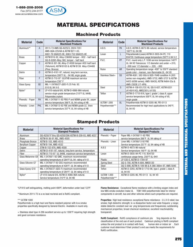
1-888-208-2008Fax (973) 244-9177
www.accuratescrew.com
MAT
ER
IAL
AN
D T
EC
HN
ICA
L S
PE
CIF
ICA
TIO
NS
275
*LP/410 self extinguishing, melting point 480ºF, deformation under load 122ºF
**Aluminum 2011i-T3 is a no lead ma terial and is RoHS compliant.
*** ULTEM 1000 Polyethermide is a high hea t and flame resistant polymer with lo w smokeproperties specifically designed by General Electric. Available in round only.
+ Stainless steel type A-286 excellent service up to 1300°F requiring high strengthand good corrosion resistance.
Flame Resistance: Exceptional flame resistance with a limiting oxygen index andlow NBS smoke evolution make UL TEM 1000 polyethermide ideal for interiorcomponents in aircraft, bus and other vehicles where such properties are required.
Properties: High heat resistance; exceptional flame retardance - U.L.V-O rated; lowsmoke; high dielectric strength; lo w dissipation factor over wide frequenc y range;stable dielectric constant over var ying tempera tures and frequencies; outstandingmechanical properties; broad chemical resistance; excellent machinability;transparent.
RoHS Compliant: RoHS compliance of cadmium pla ting depends on theclassification of the end use of each product. Cadmium plating is RoHS compliantunless the end product is in contact with food, human skin or indoor air . Eachcustomer must determine if their product's end use meets the requirements forRoHS certification.
CodeMaterial Material Specifications For Machined Products
MATERIAL SPECIFICATIONS
Machined Products
CodeMaterial Material Specifications For Machined Products
Stamped Products
Aluminum** A 2011i-T3 AMS QQ-A225/3, 2024-T351 AMS-QQA-225/6A & ASTM B211-03,6061-T6 QQA225 8E, 6063-T52 QQA225-8E
Brass B ASTM B16-92, Alloy-C36000 temper - HO2 - half hard QQ-B-626D-Alloy 360, temper - half hard
Copper C ASTM-B-301-96, Alloy-C14500 temper-HO2-half hard (Tellurium); ASTM B103 & ASTM B139 Alloy-C54400 (Phos. Bronze)
Delrin D ASTM-D-4181-97, natural, long term service,temperature 200°F UL - 94 HB, virgin grade
Fiber F ASTM-D-710-97 UL97HB maximum service temperature 230° F
Glass Epoxy GE MIL-1-24768/27-(GEE-F) 25 Feb. 92.G10 UL 94 V-0
Nylon* N LP-410-natural 6/6, ASTM-D-4066-96A natural,service virgin grade temperature 210°F UL 94HB,Polyamides (nylon)
Phenolic - Paper PH MIL-I-24768/11-92 PBG-P and NEMA grade XX, paper service temperature 266°F, UL 94 rating of HB
Phenolic - Linen PHL MIL-I-24768/13-92 FBE and NEMA grade LE, linen service temperature 257°F, UL 94 rating of HB
A.B.S. PA A.B.S. ASTM-D-4673-96-natural, service temperature 160°F UL-94 HB
Lexan L Polycarbonate (Lexan) ASTM-D-3935-94-PC, 110 B34720. Continuous usage temperature 250°F U-94 V-2
P.V.C. PP P.V.C. round only L.P. 1036 service temperature 140°F UL-94 VO Tolerances: 1/2 diameter and under +.010,-.000 over 1/2 diameter + .020, -.000
Rulon AR Operating temperature range -400° to 550°F standard grade color - maroon, non-flammable UL -94 V0
Stainless Steel+ SS ASTM-A581, 582-95b & QQS-764B condition A (303 series non-magnetic); AMS-5732, AMS-5737 & ASTM-A453 (A286 series); AMS-5643Q, ASTM A484-03a & AMS-2303E (17-4PH)
Steel S ASTM-A-108-03 (12L14), QQ-S-637, ASTM A331 (4140/4142), AMS2301J (4130)
Teflon T ASTM-D-1710-91A, type I, grade I, class A; upper service temperature 500°F, UL 94 rating of V0,virgin grade
ULTEM 1,000 UL Polyethermide ASTM-D-5205-96, PEI-0113 Polyethermide*** Recommended for high heat applications to 340°F,
UL 94 VO
Material Material Specifications ForStamped Products
Material Material Specifications ForStamped Products
Aluminum QQ-A250/1F thru QQ-A250/29A ASTM-B-209-93, AMS 4037Brass ASTM-B-36-91 AEL, AMS-4505Phosphate Bronze ASTM B-103, AMS-4510Beryllium Copper ASTM B-194, AMS-4532Copper STM-B-152-97A, AMS-4500Delrin ASTM-D-4181-97, natural, long term service, temperatureFiber ASTM-D-710-97 UL 94HB, maximum service temperatureGlass Melamine-G9 MIL-I-24768/1-92 GME, maximum recommended
operating temperature of 284°F UL 94 rating of V-OGlass Silicone-G7 MIL-I-24768/17-92 GSG maximum recommended
operating temperature of 428°F UL 94 rating of V-OGlass Epoxy-G10 MIL-I-24768/27-(GEE-F) maximum recommended
operating temperature of 284°F UL 94 rating of V-ONylon* LP-410-natural 6/6, ASTM-D-4066-96A natural.
Service temperature 210°F UL 94 HB
Phenolic - Paper Paper MIL-I-24768/11-92 PBGservice temperature 266°F UL 94 rating of
Phenolic - Linen Linen MIL-I-24768/13 92 FBE Service temperature 257°F UL 94 rating of HB
A.B.S ASTM-D-4673-96-natural Service temperature 160°F UL-94 HB
Lexan ASTM-D-3935-94-PC 110, B34720 continuous usage temp. 250°F UL-94 V
Plastic LP-535-E, ASTM-D-1784-97Spring Steel QQ-S-700, ASTM-A-684, AMS5120Steel QQ-S-698, ASTM-A-109-98 & A-366-366m-97, AMS 5040Teflon ASTM-D-3293, ASTM-D-1710-96, type I, grade I, class A
UL 94 VOULTEM 1,000 ASTM-D-5205-96, PEI-0113 UL 94 VOPolyethermide***
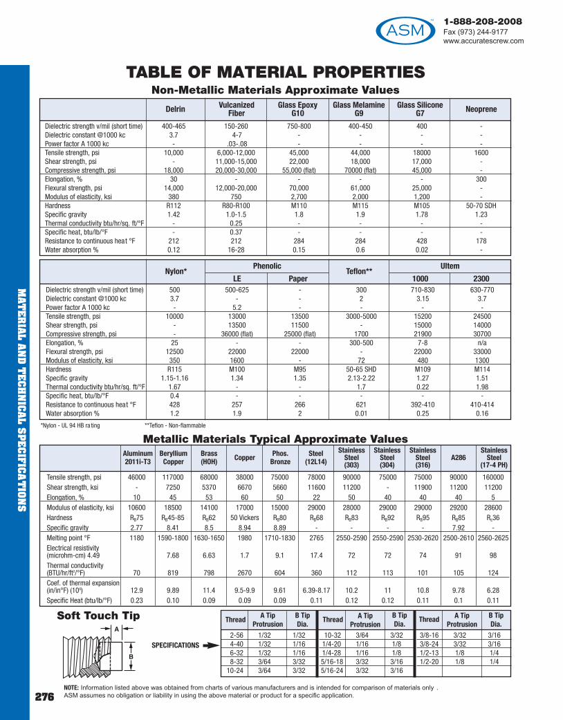
1-888-208-2008Fax (973) 244-9177www.accuratescrew.com
MAT
ER
IAL A
ND
TE
CH
NIC
AL S
PE
CIFIC
AT
ION
S
Dielectric strength v/mil (short time) 500 500-625 - 300 710-830 630-770Dielectric constant @1000 kc 3.7 - - 2 3.15 3.7Power factor A 1000 kc - 5.2 - - - -Tensile strength, psi 10000 13000 13500 3000-5000 15200 24500Shear strength, psi - 13500 11500 - 15000 14000Compressive strength, psi - 36000 (flat) 25000 (flat) 1700 21900 30700Elongation, % 25 - - 300-500 7-8 n/aFlexural strength, psi 12500 22000 22000 - 22000 33000Modulus of elasticity, ksi 350 1600 - 72 480 1300Hardness R115 M100 M95 50-65 SHD M109 M114Specific gravity 1.15-1.16 1.34 1.35 2.13-2.22 1.27 1.51Thermal conductivity btu/hr/sq. ft/°F 1.67 - - 1.7 0.22 1.98Specific heat, btu/lb/°F 0.4 - - - - -Resistance to continuous heat °F 428 257 266 621 392-410 410-414Water absorption % 1.2 1.9 2 0.01 0.25 0.16
Nylon*LE Paper
Teflon**1000 2300
Dielectric strength v/mil (short time) 400-465 150-260 750-800 400-450 400 -Dielectric constant @1000 kc 3.7 4-7 - - - -Power factor A 1000 kc - .03-.08 - - - -Tensile strength, psi 10,000 6,000-12,000 45,000 44,000 18000 1600Shear strength, psi - 11,000-15,000 22,000 18,000 17,000 -Compressive strength, psi 18,000 20,000-30,000 55,000 (flat) 70000 (flat) 45,000 -Elongation, % 30 - - - - 300Flexural strength, psi 14,000 12,000-20,000 70,000 61,000 25,000 -Modulus of elasticity, ksi 380 750 2,700 2,000 1,200 -Hardness R112 R80-R100 M110 M115 M105 50-70 SDHSpecific gravity 1.42 1.0-1.5 1.8 1.9 1.78 1.23Thermal conductivity btu/hr/sq. ft/°F - 0.25 - - - -Specific heat, btu/lb/°F - 0.37 - - - -Resistance to continuous heat °F 212 212 284 284 428 178Water absorption % 0.12 16-28 0.15 0.6 0.02 -
Tensile strength, psi 46000 117000 68000 38000 75000 78000 90000 75000 75000 90000 160000Shear strength, ksi - 7250 5370 6670 5660 11600 11200 - 11900 11200 11200Elongation, % 10 45 53 60 50 22 50 40 40 40 5Modulus of elasticity, ksi 10600 18500 14100 17000 15000 29000 28000 29000 29000 29200 28600Hardness RB75 RB45-85 RB62 50 Vickers RB80 RB68 RB83 RB92 RB95 RB85 Rc36Specific gravity 2.77 8.41 8.5 8.94 8.89 - - - - 7.92 -Melting point °F 1180 1590-1800 1630-1650 1980 1710-1830 2765 2550-2590 2550-2590 2530-2620 2500-2610 2560-2625Electrical resistivity(microhm-cm) 4.49 7.68 6.63 1.7 9.1 17.4 72 72 74 91 98Thermal conductivity (BTU/hr/ft2/°F) 70 819 798 2670 604 360 112 113 101 105 124Coef. of thermal expansion (in/in°F) (106) 12.9 9.89 11.4 9.5-9.9 9.61 6.39-8.17 10.2 11 10.8 9.78 6.28Specific Heat (btu/lb/°F) 0.23 0.10 0.09 0.09 0.09 0.11 0.12 0.12 0.11 0.1 0.11
Metallic Materials Typical Approximate Values
SPECIFICATIONS
NOTE: Information listed above was obtained from charts of various manufacturers and is intended for comparison of materials only . ASM assumes no obligation or liability in using the above material or product for a specific application.
TABLE OF MATERIAL PROPERTIESNon-Metallic Materials Approximate Values
*Nylon - UL 94 HB ra ting **Teflon - Non-flammable
Soft Touch Tip
Delrin VulcanizedFiber
Glass EpoxyG10
Glass MelamineG9
Glass SiliconeG7 Neoprene
2-56 1/32 1/324-40 1/32 1/166-32 1/32 1/168-32 3/64 3/32
10-24 3/64 3/32
10-32 3/64 3/321/4-20 1/16 1/81/4-28 1/16 1/85/16-18 3/32 3/165/16-24 3/32 3/16
3/8-16 3/32 3/163/8-24 3/32 3/161/2-13 1/8 1/41/2-20 1/8 1/4
Thread A TipProtrusion
B TipDia.
Thread A TipProtrusion
A TipProtrusion
Thread B TipDia.
B TipDia.
Phenolic Ultem
Aluminum2011i-T3
BerylliumCopper
Brass(HOH) Copper Phos.
BronzeSteel
(12L14)
StainlessSteel(303)
StainlessSteel(304)
StainlessSteel(316)
A286Stainless
Steel(17-4 PH)
276

1-888-208-2008Fax (973) 244-9177
www.accuratescrew.com
MAT
ER
IAL
AN
D T
EC
HN
ICA
L S
PE
CIF
ICA
TIO
NS
277
1 NO FINISH
2 ANODIZE - MIL-A-8625F - Type II - Class 2 - (sulphuric)Hot water seal (dk. gray)
3 ANODIZE - MIL-A 8625F - Type II - Class 1 - (sulphuric)Hot water seal (clear)
3a ANODIZE - MIL-A-8625F - Type II - Class 2 - (sulphuric)Hot water seal (blue)
3b ANODIZE - MIL-A-8625F - Type II - Class 2 - (sulphuric)Hot water seal (red)
4b ANODIZE - MIL-A-8625F - Type II - Class 2 - (d yed gold)
5 ANODIZE - MIL-A-8625F - Type II - Class 2Hot water seal (black)
6 CADMIUM PLATE - SAE-AMS-QQ-P-416 - Type I - Class 2*Clear chromate
6a CADMIUM PLATE - SAE-AMS-QQ-P-416 - Type II - Class 2*Color chromate finish
7 CADMIUM PLATE COMMERCIAL - Type I - Classes 1, 2, 3*
8 CADMIUM PLATE - SAE-AMS-QQ-P-416 - Type II - Class 3*Color chromate finish
9 NICKEL PLATE - SAE-AMS-QQ-N-290 1 - Grade G (Thickness - .0002-SB) (single layer coa ting fully bright)
9a NICKEL PLATE - SAE-AMS-QQ-N-290 1 - Grade F(Thickness - .0004-SB) (single layer coa ting fully bright)
10 SILVER PLATE - ASTM-B700 - Type II - Grade B (thickness -.0003)99-S-365
11 BLACK OXIDE - MIL-DTL-13924D - Class 4For 300 series corrosion resistance steel allo ys only
11a BLACK OXIDE - MIL-DTL-13924D - Class 1(For plain carbon and low alloy steels)
12 PASSIVATE - MIL-F-14072-D (ER) AMEND #1 - Type I(Finish #E300 - passivate per ASTM-A-380-96)
12a PASSIVATE - AMS-QQ-P-35, ASTM A967 - Type II
15 ALODINE 1200**
16 GOLD FLASH (thickness -.00003 to .00005)
17 GOLD FLASH over nickel flash (thickness - .00003 to .00005)
18 GOLD PLATE - AMS 2422, ASTM B488 - Type II - Grade C -Class 2 (thickness .00010 minimum)
19 TIN PLATE - (hot dipped) ASTM B 339 “PIG TIN”Grade A - Type II
20 TIN PLATE - (electro deposit) ASTM 8545 - Type IMIL-T-10727
20a TIN PLATE - (electro deposit) plus solderability ASTM B 545-92 - Class C
20b TIN/LEAD - per ASTM B579**
21 BRIGHT DIP (brass finish)
22 CHEMICAL FILM - MIL-C-5541-E - Class 3 (c lear)
23 CHEMICAL FILM - MIL-C-5541-E - Class 1a (gold)**
24 GOLD FLASH - 0.000015 thick over silver pla te(0.0003 thickness)
26 CHROMIUM PLATING - SAE-AMS-QQ-C-320 (bright finish)Class 1 - Type I
27 CHROMIUM PLATING - SAE-AMS-QQ-C-320 (satin finish)Class 1 - Type II
28 CHROMIUM PLATING - SAE-AMS-QQ-C-320 (engineering)Class 2
29 CLEAR LACQUER
30 WATER DIP LACQUER
31 ZINC PLATE - ASTM B633/85 Type I - Class FE/ZN5-SC-1(thickness .00025)
31a ZINC PLATE - colored chromate - ASTM B633/85Type II - FE/ZN5- SC-1 (thickness -.00025)
31b ZINC PLATE - colorless (clear) chromate - ASTM B633/85,Type III - Class FE/ZN5-S.C-1 (thickness .00025)
31d ZINC PLATE - (phosphate coat) - ASTM B633/85 - Type VClass FE/ZN5-SC-1 (thickness .00025)
31e ZINC PLATE - per ASTM B633 - Type II - (olive drab)
32 SOLDER PLATE - (.0001 TO -.0003 thick; solder per J-STD-004,SN 60 PG 40) over nickel pla te thickness 0.0001-0.0005 in AC/W SAE-AMS-P-81728 plus solderability
34 BLACK PHOSPHATE - DOD-DTL-16232 TYZ TYM
35 BLACK ZINC - QQ-Z-325 - TYPE II
37 BLACK FINISH - (used on steel parts - strictly cosmetic)
38 ELECTRO TIN PLATE - over copper flash - ASTM B545 - Type I
39 LUBRICANT - Solid film - hea t cured - corrosion inhibiting -MIL-PRF-46010F - Type I - cure tempera ture of 150 +3°C
39a LUBRICANT - Solid film - hea t cured - corrosion inhibiting -MIL-PRF-46010F - Type II - cure temperature of 204 +3°CTypes II and III
40 ELECTRO POLISH - No militar y specification assigned. Anelectric process used to remove the outer layer of ma terial tobrighten primarily steel, stainless steel and brass alloys.
FINISHES
*RoHS Compliant: RoHS compliance of cadmium pla ting depends on the classificationof the end use of each product. Cadmium plating is RoHS compliant unless the endproduct is in contact with food, human skin or indoor air. Each customer mustdetermine if their product's end use meets the requirements for RoHS certifica tion.
**These plating codes are not RoHS compliant and we do not offer a substitute for these platings. Do not specify these finishes if RoHS certifica tion is required.
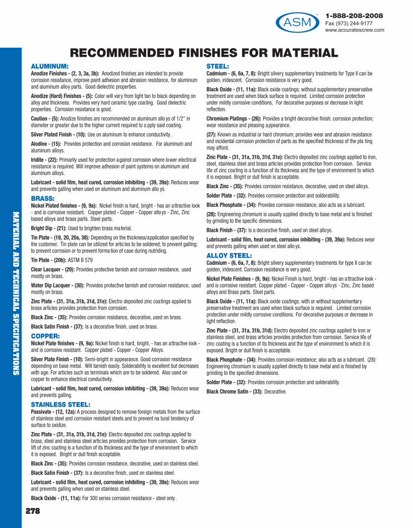
1-888-208-2008Fax (973) 244-9177www.accuratescrew.com
MAT
ER
IAL A
ND
TE
CH
NIC
AL S
PE
CIFIC
AT
ION
S
278
ALUMINUM:Anodize Finishes - (2, 3, 3a, 3b): Anodized finishes are intended to providecorrosion resistance, improve paint adhesion and abrasion resistance, for aluminumand aluminum alloy parts. Good dielectric properties.
Anodize (Hard) Finishes - (5): Color will vary from light tan to black depending onalloy and thickness. Provides very hard ceramic type coa ting. Good dielectricproperties. Corrosion resistance is good.
Caution - (5): Anodize finishes are recommended on aluminum allo ys of 1/2" indiameter or greater due to the higher current required to a pply said coating.
Silver Plated Finish - (10): Use on aluminum to enhance conductivity.
Alodine - (15): Provides protection and corrosion resistance. For aluminum andaluminum alloys.
Iridite - (22): Primarily used for protection against corrosion where lower electricalresistance is required. Will improve adhesion of paint systems on aluminum andaluminum alloys.
Lubricant - solid film, heat cured, corrosion inhibiting - (39, 39a): Reduces wearand prevents galling when used on aluminum and aluminum allo ys.
BRASS:Nickel Plated finishes - (9, 9a): Nickel finish is hard, bright - has an a ttractive look- and is corrosive resistant. Copper plated - Copper - Copper allo ys - Zinc, Zincbased alloys and brass parts. Steel parts.
Bright Dip - (21): Used to brighten brass material.
Tin Plate - (19, 20, 20a, 38): Depending on the thickness/application specified bythe customer. Tin plate can be utilized for artic les to be soldered; to prevent galling;to prevent corrosion or to prevent forma tion of case during nutriding.
Tin Plate - (20b): ASTM B 579
Clear Lacquer - (29): Provides protective tarnish and corrosion resistance, usedmostly on brass.
Water Dip Lacquer - (30): Provides protective tarnish and corrosion resistance, usedmostly on brass.
Zinc Plate - (31, 31a, 31b, 31d, 31e): Electro deposited zinc coatings applied tobrass articles provides protection from corrosion.
Black Zinc - (35): Provides corrosion resistance, decorative, used on brass.
Black Satin Finish - (37): Is a decorative finish, used on brass.
COPPER:Nickel Plate finishes - (9, 9a): Nickel finish is hard, bright, - has an attractive look -and is corrosive resistant. Copper plated - Copper - Copper Alloys.
Silver Plate Finish - (10): Semi-bright in appearance. Good corrosion resistancedepending on base metal. Will tarnish easily. Solderability is excellent but decreaseswith age. For articles such as terminals which are to be soldered. Also used oncopper to enhance electrical conductivity.
Lubricant - solid film, heat cured, corrosion inhibiting - (39, 39a): Reduces wearand prevents galling.
STAINLESS STEEL:Passivate - (12, 12a): A process designed to remove foreign metals from the surfaceof stainless steel and corrosion resistant steels and to prevent na tural tendency ofsurface to oxidize.
Zinc Plate - (31, 31a, 31b, 31d, 31e): Electro deposited zinc coatings applied tobrass, steel and stainless steel articles provides protection from corrosion. Servicelift of zinc coating is a function of its thickness and the type of environment to whichit is exposed. Bright or dull finish acceptable.
Black Zinc - (35): Provides corrosion resistance, decorative, used on stainless steel.
Black Satin Finish - (37): Is a decorative finish, used on stainless steel.
Lubricant - solid film, heat cured, corrosion inhibiting - (39, 39a): Reduces wearand prevents galling when used on stainless steel.
Black Oxide - (11, 11a): For 300 series corrosion resistance - steel only .
STEEL:Cadmium - (6, 6a, 7, 8): Bright silvery supplementary treatments for Type II can begolden, iridescent. Corrosion resistance is very good.
Black Oxide - (11, 11a): Black oxide coatings; without supplementary preservativetreatment are used when black surface is required. Limited corrosion protectionunder mildly corrosive conditions, For decorative purposes or decrease in lightreflection.
Chromium Platings - (26): Provides a bright decorative finish; corrosion protection;wear resistance and pleasing appearance.
(27): Known as industrial or hard chromium; provides wear and abrasion resistanceand incidental corrosion protection of parts as the specified thickness of the pla tingmay afford.
Zinc Plate - (31, 31a, 31b, 31d, 31e): Electro deposited zinc coatings applied to iron,steel, stainless steel and brass articles provides protection from corrosion. Servicelife of zinc coating is a function of its thickness and the type of environment to whichit is exposed. Bright or dull finish is acceptable.
Black Zinc - (35): Provides corrosion resistance, decorative, used on steel alloys.
Solder Plate - (32): Provides corrosion protection and solderability.
Black Phosphate - (34): Provides corrosion resistance; also acts as a lubricant.
(28): Engineering chromium is usually applied directly to base metal and is finishedby grinding to the specific dimensions.
Black Finish - (37): Is a decorative finish, used on steel alloys.
Lubricant - solid film, heat cured, corrosion inhibiting - (39, 39a): Reduces wearand prevents galling when used on steel allo ys.
ALLOY STEEL:Cadmium - (6, 6a, 7, 8): Bright silvery supplementary treatments for type II can begolden, iridescent. Corrosion resistance is very good.
Nickel Plate Finishes - (9, 9a): Nickel Finish is hard, bright - has an a ttractive look -and is corrosive resistant. Copper plated - Copper - Copper allo ys - Zinc, Zinc basedalloys and Brass parts. Steel parts.
Black Oxide - (11, 11a): Black oxide coatings; with or without supplementar ypreservative treatment are used when black surface is required. Limited corrosionprotection under mildly corrosive conditions. For decorative purposes or decrease inlight reflection.
Zinc Plate - (31, 31a, 31b, 31d): Electro deposited zinc coatings applied to iron orstainless steel, and brass articles provides protection from corrosion. Service life ofzinc coating is a function of its thickness and the type of environment to which it isexposed. Bright or dull finish is acceptable.
Black Phosphate - (34): Provides corrosion resistance; also acts as a lubricant. (28):Engineering chromium is usually applied directly to base metal and is finished bygrinding to the specified dimensions.
Solder Plate - (32): Provides corrosion protection and solderability.
Black Chrome Satin - (33): Decorative.
RECOMMENDED FINISHES FOR MATERIAL

1-888-208-2008Fax (973) 244-9177
www.accuratescrew.com
MAT
ER
IAL
AN
D T
EC
HN
ICA
L S
PE
CIF
ICA
TIO
NS
279
Length of ThreadBrass, Aluminum & Steel Parts: M2.5 thread is tapped thru15.9MM in length. M3 and larger thread is ta pped thru 25.4 MMin length.
Stainless Steel & Nylon Parts: M2.5 thread is tapped thru 9.6MM in length M3 thread is ta pped thru 12.7 MM in length.
M3.5 and larger thread is ta pped thru 25.4MM in length. Forlengths longer than specified above, see DEPTH OF THREADCHART.
Choose American Standard part number from our ca talog.EXAMPLE OF MALE FEMALE STANDOFF:14010-H-SS-.625-12
Then simply add your metric requirements to our part number .EXAMPLE:14010-H-SS-.625-12 (M3.0 x .5 Thread)
Or if you need a longer Male thread:EXAMPLE: 14010-H-SS-.625-12 (B = 3.0 x .5 Thread, B= 7.5 MM Length)
NOTE: When the body length L is less than or equal to the thread depth A we will provide the maximum number of threads possible.
Step 1 Choose American Standard part number from our ca talog.EXAMPLE OF THREADED SPACER: 1130-R-SS- .250-12
Step 2 Simply add your metric requirements to our part number .EXAMPLE OF METRIC THREADED SPACER: 1130-R-SS-.250-12 (M 3.5 x 0.6 Thd.) Just add requirement here.
M 2.5 x .45 3.97 4.763.0 x 0.5 4.76 6.353.5 x 0.6 6.35 9.534.0 x 0.7 9.53 11.105.0 x 0.8 9.53 12.706.0 x 1.0 12.70 15.008.0 x 1.25 12.70 15.00
Metric Thread A Min Depth
B
1.6 x 0.35 1.8 - 2.12.0 x 0.40 2.2 - 2.82.5 x 0.45 2.7 - 3.13.0 x 0.50 3.2 - 3.63.5 x 0.60 3.5 - 4.24.0 x 0.70 4.2 - 4.85.0 x 0.80 5.3 - 6.06.0 x 1.00 6.3 - 7.06.3 x 1.00 6.7 - 7.58.0 x 1.25 8.5 - 9.5
M1.6 x 0.352.0 x 0.402.5 x 0.45 3.0 x 0.503.5 x 0.604.0 x 0.705.0 x 0.806.0 x 1.008.0 x 1.25
10.0 x 1.5012.0 x 1.7514.0 x 2.00
M 2.5 4.8mm 3.0 8.43.5 9.54.0 11.15.0 12.76.0 14.38.0 14.3
Diameter x Pitch
ClearanceHole Range
Diameter x Pitch Thread SizeScrew
Engagement
MALE/FEMALE SPECIFICATION
Clearance HoleRecommendedThread Sizes
Depth of Thread Recommended blind hole
thread engagement (drilled and tapped both ends)
METRIC SPECIFICATIONS
Just add requirement here.
Just add requirement here.
Metric Thread
METRIC THREADS
CONVERSION TABLETo convert inches to millimeters multiply inches x 25.4
To convert millimeters to inches multiply millimeters x 0.039370
SPACERSTolerances in manufacture of Standoffs and Spacers
Length: up to 100MM long +.13 MM O.D. +.152 MM
HOW TO ORDER METRIC MALE/FEMALE STANDOFF
HOW TO ORDER METRIC PARTS

1-888-208-2008Fax (973) 244-9177www.accuratescrew.com
MAT
ER
IAL A
ND
TE
CH
NIC
AL S
PE
CIFIC
AT
ION
S
280
METRIC SCREW SPECIFICATIONSFOR REFERENCE ONLY
Oval Head Machine Screw
Thread Size d M2 M2.5 M3 M4 M5 M6Head Hght Max k 1.7 2.1 2.4 3.7 3.9 4.7Head Dia Max d2 4.4 5.5 6.3 9.4 10.4 12.6Driver Size No. 1 1 1 2 2 3
Slotted Phillips
Dimensions in millimeters
Pan HeadCross RecessedMachine Screw
Thread Size d M2 M2.5 M3 M4 M5 M6Head Hght k 1.6 2 2.4 3.1 3.8 4.6Head Dia d2 4 5 6 8 10 12Driver Sz No. 1 1 1 2 2 3
Dimensions in millimeters
Socket Head Cap Screw
Thread Size d M3 M4 M5 M6 M8 M10 M12 M14 M16 M20Head Hght k 3 4 5 6 8 10 12 14 16 20Head Dia d2 5.5 7 8.5 10 13 16 10 21 24 30Hex Key Sz s 2.5 3 4 5 6 8 10 12 14 17
Dimensions in millimeters
Button Head
5.7 1.65 27.6 2.20 2.59.5 2.75 3
10.5 3.30 414.0 4.40 517.5 5.50 621.0 6.60 828.0 8.80 10
Head Dia.B Max.
Head HgtR Max
Socket SzS Nom.
Dimensions in millimeters
Pan HeadSlottedMachine Screw
Thread Size d M3 M4 M5 M6Head Hght k 1.8 2.4 3 3.6Head Dia d2 6 8 10 12Pitch p .50 .70 .80 1
Dimensions in millimeters
Flat HeadMachine Screw
Thread Size d M2 M2.5 M3 M4 M5 M6 M8 M10Head Hght k 1.2 1.5 1.65 2.2 2.5 3 4 5Head Dia d2 3.8 4.7 5.6 7.5 9.2 11 14.5 18Pitch p .40 .45 .50 .7 .8 1 1.25 1.50
Slotted Phillips
Dimensions in millimeters
Hexagon HeadCap Screw
Thread Size d M4 M5 M6 M8 M10 M12 M14 M16 M20 M24Head Hght k 2.8 3.5 4 5.5 7 8 9 10 13 15Across Flats s 7 8 10 13 17 19 22 24 30 36Pitch p.7 .8 1 1.25 1.5 1.75 2 2 2.5 3
Dimensions in millimeters
Important Data,Metric Machine Screws Position of Head : The axis of the head
shall be loca ted at true position rela tiveto the axis of the screw shank within atolerance zone ha ving a diameterequivalent to 6% of the specifiedmaximum head diameter , or thespecified maximum width across flats ofhex and hex flange heads, regardless offeature size.
All tolerances are plus and minus.
to 3 mm incl. 0.2over 3 to 10 mm 0.3over 10 to 16 mm 0.4over 16 to 50 mm 0.5
over 50 mm 1.0
Nom ScrewLength
Toleranceon Length
mm

1-888-208-2008Fax (973) 244-9177
www.accuratescrew.com
MAT
ER
IAL
AN
D T
EC
HN
ICA
L S
PE
CIF
ICA
TIO
NS
281
IMPORTANT DATA: MACHINE SCREWSECCENTRICITY: The heads of machine screws shall not beeccentric with the body beyond a tolerance of 3% of the maximumhead diameter.TOLERANCE IN LENGTH: The length for socket head ca p screwclass 3A UNRC see table on pa ge 286.
THREAD INFORMATION
0-80 3/8 1/4 3/161-72 3/8 1/4 3/162-56 1/2 3/8 3/163-48 1/2 3/8 3/16 3-56 1/2 3/8 3/164-40 1 3/4 1/44-48 1 3/4 1/45-40 1 3/4 5/166-32 1 3/4 3/86-40 1 3/4 3/88-32 1 3/4 7/1610-24 1 3/4 1/210-32 1 3/4 1/212-24 1 3/4 1/21/4-20 1-1/4 1-1/4 5/81/4-28 1-1/4 1-1/4 5/85/16-18 1-1/4 1-1/4 5/85/16-24 1-1/4 1-1/4 5/83/8-16 1-1/4 1-1/4 5/83/8-24 1-1/4 1-1/4 5/87/16-14 1-1/4 1-1/4 5/87/16-20 1-1/4 1-1/4 5/81/2-13 1-1/4 1-1/4 5/81/2-20 1-1/4 1-1/4 5/8
Thread LAluminum, Brass,
Steel, Nylon
LStainless Steel
LAluminum, Brass, Steel, St. Steel,
Nylon Min Screw Engagement
L Length Not Longer than Shown Blind Tap Depth Min.
NOTES:1. Threads are supplied cut or rolled a t our option unless specifically noted on order .2. Responsibility ends with customer inspection or 10 days after customer receives parts. No returns will be accepted without pri or approval from factory in writing.3. All parts are stocked in plain finish. Parts will be plated to customer specifications.4. The items in this ca talog are designed and manufactured to be functional. Engineering evaluation and quality assurance evalua tions should be accomplished withfunctionability as a prime criteria.5. All threads are Class 2A and Class 2B Commercial, except Socket Head Cap Screws which are Class 3A Threads. Once plated will not enter 3A GO andNO GO GAGES.
Tapped thru when LLength is NOT longer
than dimensionshown.
Use the “BlindTap Depth” partof chart belowwhen L Lengthis longer thanshown at left.
TOLERANCESAll dimensions in inches unless otherwise specified.
Two Place Decimal . . . . . . . .+.010Three Place Decimal . . . . . .+.005Fractions . . . . . . . . . . . . . . .+1/64"
Note:1. Up to 4" long all spacers and standoffs are kept to + .005.2. 4" to 6" long +.008.3. Over 6" long +.010.
SPECIAL CLOSE TOLERANCES are available.Just add to part number.
EXAMPLE: 2030R - A - .500 - 1 (MOD L=+.002)DIAMETER: St’d Commercial Tolerances on bar & rod.
ROUND - COLD FINISHED: Under 5/16" . . . . . . . . . . . .+.001"5/16" to 1/2", incl. . . . . . . . .+.00151/2" to 1", incl. . . . . . . . . . .+.002
SURFACES63
NOMINAL SCREW SIZE 0 - 12 1/4 - 3/4
NOMINAL SCREW LENGTH TOLERANCE ON LENGTH
Up to 1/2 in., incl. -0.02 -0.03Over 1/2 to 1 in., incl -0.03 -0.03Over 1 to 2 in., incl. -0.06 -0.06Over 2 in., incl. -0.09 -0.09
NOMINAL SCREW SIZE 0 - 12 1/4 - 3/4NOMINAL SCREW LENGTH TOLERANCE ON LENGTH
Up to 1/2 in., incl. -0.03 -0.04Over 1/2 to 1 in., incl -0.04 -0.04Over 1 to 2 in., incl. -0.07 -0.07Over 2 in., incl. -0.09 -0.09
FOR LEAD POINT CAPTIVE SCREW ONLY
SCREWDRIVER SLOTDIMENSIONS
Unless otherwise specified
OD Diameter W HMax Max Min Max Min
Up to .160 .031 .023 .030 .022.161 to .182 .035 .027 .034 .026.183 to .204 .039 .031 .038 .030.205 to .225 .039 .031 .042 .025.226 to .269 .048 .039 .053 .033.270 to .312 .054 .045 .074 .052.313 to .413 .060 .050 .080 .057.414 and up .075 .064 .111 .083

1-888-208-2008Fax (973) 244-9177www.accuratescrew.com
MAT
ER
IAL A
ND
TE
CH
NIC
AL S
PE
CIFIC
AT
ION
S
282
Galvanic Corrosion
Similar metals are compatible; dissimilar metals are not . Whendissimilar metals contact in the presence of an electrolyte, agalvanic action occurs which causes one of the metals to corrodeat a much faster than normal rate, while the other corrodes moreslowly, if at all. The rate, location and extent of the corrosiondepends on three factors:
– the difference in electrical potentials– the conductivity strength of the corroding medium – the relative sizes of the contacting areas
All metals have electrical potentials. Through research, thepotentials of different base metals and their alloys, when exposedto sea water, were measured and then ranked into a series.
Galvanic Series
Table 1 presents the Galvanic Series of Metals and Alloys. Thevarious metals are grouped. Those within the same group arereasonably compatible when used together; those from dif ferentgroups cause a corrosion problem. Some metals – basically thosewith significant contents of nickel and chromium – are included inthe Series both in their active and passive conditions. Passivation(surface cleaning and sealing) lowers the metal’ s electricalpotential and improves its corrosion behavior.
In an electrical couple, the metal of higher electrical potential is thecathode (-), that of the lower the anode (+). Current flows from thecathode to the anode, from the anode through the electrolyte(corroding medium) and back to the cathode. Corrosion occurs atthe point the current leaves the anode to enter the electrolyte.When dissimilar metals contact, the anode corrodes, the cathodesurvives.
Study of the Galvanic Series suggests that steel and aluminum arereasonably compatible; but, if titanium and aluminum contact, thealuminum, as the anode, will corrode. Fig. 1 illustrates an example.The bolt, where it contacts the aluminum, will not corrode, becauseit is now the cathode. The aluminum plate in contact with the boltmay corrode, but only slightly because of the minor dif ference intheir electropotentials and the large anode-to-cathode area ratio.The aluminum plate will corrode where its exposed exteriorsurfaces contact the copper plate. The aluminum plate may alsocorrode on its interior surface, but not to the same degree, becausethe corroding medium and oxygen supply are largely sealed outdue to the bolt’s clamping action.
+ Corroded End (anodic, or least noble)MagnesiumMagnesium alloys ZincAluminum 1100CadmiumAluminum 2024-T4Steel or IronCast IronChromium-Iron (active)Ni-Resist cast ironType 304 Stainless (active)Type 316 Stainless (active)Lead tim soldersLeadTinNickel (active)Inconel nickel-chromium alloy (active)Hastelloy Alloy C (active)BrassCopperBronzesCopper-nickel alloysMonel nickel-copper alloySilver solderNickel (passive)Inconel nickel-chromium alloy (passive)Chromium-Iron (passive)Type 304 Stainless (passive)Type 316 Stainless (passive)Hastelloy Alloy C (passive)SilverTitaniumGraphiteGoldPlatinum– Protect End (cathodic, or most noble)
• Table 1 •Galvanic Series of Metals and Alloys
• Figure 1 • Effects of Galvanic Corrosion
MATERIAL COMPATIBILITY SELECTION DATA

1-888-208-2008Fax (973) 244-9177
www.accuratescrew.com
MAT
ER
IAL
AN
D T
EC
HN
ICA
L S
PE
CIF
ICA
TIO
NS
283
0 0.0600 0.0600 0.0568 0.096 0.091 0.060 0.057 0.054 0.050 0.025 0.020 0.0031 0.0730 0.0730 0.0695 0.118 0.112 0.073 0.070 0.066 1/16 0.062 0.031 0.025 0.0032 0.0860 0.0860 0.0822 0.140 0.134 0.086 0.083 0.077 5/64 0.078 0.038 0.029 0.0033 0.0990 0.0990 0.0949 0.161 0.154 0.099 0.095 0.089 5/64 0.078 0.044 0.034 0.0034 0.1120 0.1120 0.1075 0.183 0.176 0.112 0.108 0.101 3/32 0.094 0.051 0.038 0.0055 0.1250 0.1250 0.1202 0.205 0.198 0.125 0.121 0.112 3/32 0.094 0.057 0.043 0.0056 0.1380 0.1380 0.1329 0.226 0.218 0.138 0.134 0.124 7/64 0.109 0.064 0.047 0.0058 0.1640 0.1640 0.1585 0.270 0.262 0.164 0.159 0.148 9/64 0.141 0.077 0.056 0.005
10 0.1900 0.1900 0.1840 0.312 0.303 0.190 0.185 0.171 5/32 0.156 0.090 0.065 0.0051/4 0.2500 0.2500 0.2435 0.375 0.365 0.250 0.244 0.225 3/16 0.188 0.120 0.095 0.0085/16 0.3125 0.3125 0.3053 0.469 0.457 0.312 0.306 0.281 1/4 0.250 0.151 0.119 0.0083/8 0.3750 0.3750 0.3678 0.562 0.550 0.375 0.368 0.337 5/16 0.312 0.182 0.143 0.0087/16 0.4375 0.4375 0.4294 0.656 0.642 0.438 0.430 0.394 3/8 0.375 0.213 0.166 0.0101/2 0.5000 0.5000 0.4919 0.750 0.735 0.500 0.492 0.450 3/8 0.375 0.245 0.190 0.0105/8 0.6250 0.6250 0.6163 0.938 0.921 0.625 0.616 0.562 1/2 0.500 0.307 0.238 0.0103/4 0.7500 0.7500 0.7406 1.125 1.107 0.750 0.740 0.675 5/8 0.625 0.370 0.285 0.0107/8 0.8750 0.8750 0.8647 1.312 1.293 0.875 0.864 0.787 3/4 0.750 0.432 0.333 0.0151 1.0000 1.0000 0.9886 1.500 1.479 1.000 0.988 0.900 3/4 0.750 0.495 0.380 0.015
See Notes 1 2,15 3 4 21 6
Nominal
SHead Side
Height
Nominal Size orBasic Screw
Diameter
JHex Socket Size
• Table 1 • Dimensions of Hexagon and Spline Socket Head Cap Screws (1960 Series)
FOR REFERENCE ONLY: SOCKET CAP SCREWS
DBody Diameter
AHead Diameter
HHead Height
TKey
Engagmt
GWall
Thkns
KChamfer or
RadiusMax Min Max Min Max Min Max Min Min Max
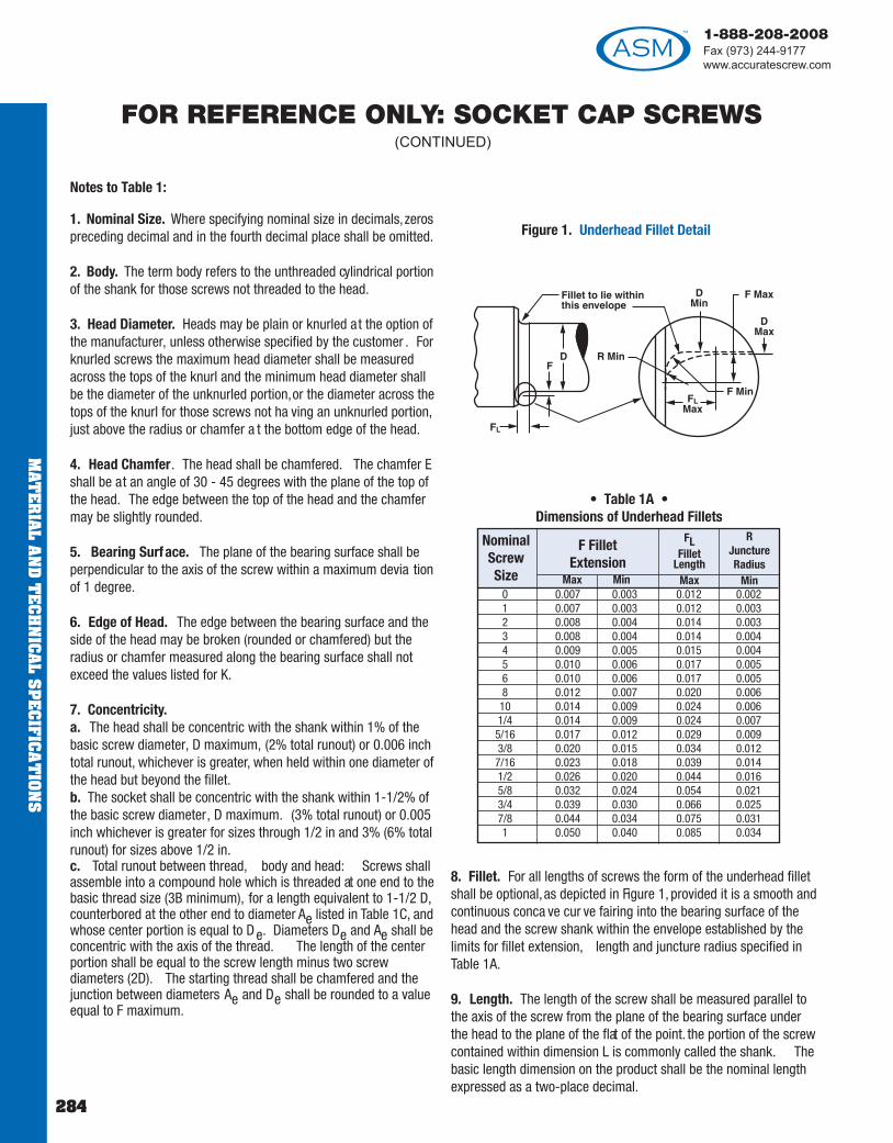
1-888-208-2008Fax (973) 244-9177www.accuratescrew.com
MAT
ER
IAL A
ND
TE
CH
NIC
AL S
PE
CIFIC
AT
ION
S
284
1. Nominal Size. Where specifying nominal size in decimals,zerospreceding decimal and in the fourth decimal place shall be omitted.
2. Body. The term body refers to the unthreaded cylindrical portionof the shank for those screws not threaded to the head.
3. Head Diameter. Heads may be plain or knurled at the option ofthe manufacturer, unless otherwise specified by the customer . Forknurled screws the maximum head diameter shall be measuredacross the tops of the knurl and the minimum head diameter shallbe the diameter of the unknurled portion,or the diameter across thetops of the knurl for those screws not ha ving an unknurled portion,just above the radius or chamfer a t the bottom edge of the head.
4. Head Chamfer. The head shall be chamfered. The chamfer Eshall be at an angle of 30 - 45 degrees with the plane of the top ofthe head. The edge between the top of the head and the chamfermay be slightly rounded.
5. Bearing Surface. The plane of the bearing surface shall beperpendicular to the axis of the screw within a maximum devia tionof 1 degree.
6. Edge of Head. The edge between the bearing surface and theside of the head may be broken (rounded or chamfered) but theradius or chamfer measured along the bearing surface shall notexceed the values listed for K.
7. Concentricity.a. The head shall be concentric with the shank within 1% of thebasic screw diameter, D maximum, (2% total runout) or 0.006 inchtotal runout, whichever is greater, when held within one diameter ofthe head but beyond the fillet.b. The socket shall be concentric with the shank within 1-1/2% ofthe basic screw diameter, D maximum. (3% total runout) or 0.005inch whichever is greater for sizes through 1/2 in and 3% (6% totalrunout) for sizes above 1/2 in.c. Total runout between thread, body and head: Screws shallassemble into a compound hole which is threaded at one end to thebasic thread size (3B minimum), for a length equivalent to 1-1/2 D,counterbored at the other end to diameter Ae listed in Table 1C, andwhose center portion is equal to De. Diameters De and Ae shall beconcentric with the axis of the thread. The length of the centerportion shall be equal to the screw length minus two screwdiameters (2D). The starting thread shall be chamfered and thejunction between diameters Ae and De shall be rounded to a valueequal to F maximum.
8. Fillet. For all lengths of screws the form of the underhead filletshall be optional,as depicted in Figure 1, provided it is a smooth andcontinuous conca ve cur ve fairing into the bearing surface of thehead and the screw shank within the envelope established by thelimits for fillet extension, length and juncture radius specified inTable 1A.
9. Length. The length of the screw shall be measured parallel tothe axis of the screw from the plane of the bearing surface underthe head to the plane of the flat of the point. the portion of the screwcontained within dimension L is commonly called the shank. Thebasic length dimension on the product shall be the nominal lengthexpressed as a two-place decimal.
Notes to Table 1:
0 0.007 0.003 0.012 0.0021 0.007 0.003 0.012 0.0032 0.008 0.004 0.014 0.0033 0.008 0.004 0.014 0.0044 0.009 0.005 0.015 0.0045 0.010 0.006 0.017 0.0056 0.010 0.006 0.017 0.0058 0.012 0.007 0.020 0.00610 0.014 0.009 0.024 0.0061/4 0.014 0.009 0.024 0.0075/16 0.017 0.012 0.029 0.0093/8 0.020 0.015 0.034 0.0127/16 0.023 0.018 0.039 0.0141/2 0.026 0.020 0.044 0.0165/8 0.032 0.024 0.054 0.0213/4 0.039 0.030 0.066 0.0257/8 0.044 0.034 0.075 0.0311 0.050 0.040 0.085 0.034
NominalScrewSize
F FilletExtension
Max Min
FLFillet
LengthMax
RJunctureRadius
Min
Figure 1. Underhead Fillet Detail
• Table 1A • Dimensions of Underhead Fillets
FOR REFERENCE ONLY: SOCKET CAP SCREWS(CONTINUED)

1-888-208-2008Fax (973) 244-9177
www.accuratescrew.com
MAT
ER
IAL
AN
D T
EC
HN
ICA
L S
PE
CIF
ICA
TIO
NS
285
10. Length Tolerances. The allowable tolerance on length shall beas tabulated below:
11. Length Tolerances. The allowable tolerance for LEAD POINTcaptive screws only shall be as tabula ted below:
12. Threads. Threads shall be Unified external threads with radiusroot: Class 3A UNC and UNF Series for screw sizes 0 (0.060 in.)through 1 in.: Class 2A UNC and UNF Series for sizes over 1 in. to1-1/2 in., inclusive: and Class 2A UNC Series for sizes larger that 1-1/2 in.
Class 3A does not provide a pla ting allo wance. When pla tedproducts are required it is recommended that they be procured fromthe manufacturer. (See paragraph 1.8).
13. Thread Length, LT. The length of thread shall be measured,parallel to the axis of screw , from the extreme point to the lastcomplete (full form) thread. The thread length on socket head ca pscrews shall be as defined by Table 1B and notes thereto.
14. Griping Gaging Length, LG. The grip ga ging length is the
distance, measured parallel to the axis of screw , from the bearingsurface of the head to the first complete (full form) thread under thehead (see Table 1B).
15. Body Length, LB. The bod y length is the length, measuredparallel to the axis of screw , of the unthreaded portion of the shank(See table 1B).
16. Screw P oint Chamfer . The point shall be fla t or slightlyconcave and chamfered. The plane of the point shall beapproximately normal to the axis of the screw . The chamfer shallextend slightly below the root of the thread and the edge betweenthe flat and chamfer may be slightly rounded. The included angleof the point should be a pproximately 90 degrees. Chamfering ofscrew sizes up to and inc luding size 8 (0.164 in.) shall be optional.
17. Material. Steel, corrosion resistant. Cap screws shall befabricated from austenitic corrosion resistant steel of types 18-8,AISI 384, or equivalent types, and shall ha ve a minimum tensilestrength of 80,000 psi for sizes up to and inc luding 5/8 in. and70,000 psi for sizes larger than 5/8 in.
18. Surface Roughness. For allo y steel screws of up to andincluding 5/8 in., and nominal lengths equal to or less than 8 timesthe basic screw diameter , the surface roughness of the screwsbefore pla ting shall not exceed 63 microinches (arithmeticalaverage) on the fillet and head bearing surfaces, nor exceed 32microinches (arithmetical average) on the threads.
For larger sizes, longer lengths, and corrosion resistant steelscrews, the surface roughness of the screws prior to pla ting shallnot exceed 125 micro-inches (arithmetical a verage) on the bod y(see Note 2), fillet (see Note 8) and head bearing surfaces.
Normally, it shall be sufficient to ascertain tha t these surfaces onscrews have the equivalent of a smooth machined finish by visualcomparison with kno w surface standards. However, where it ispractical and deemed necessar y to measure these surfaces withcommercially available equipment, roughness measurements shallbe taken axially on the bod y and fillet surfaces, andcircumferentially on the bearing surface.
19. Drawings. On socket screw drawings when the distance fromthe bearing surface of the head to the threading is dimensioned,regardless of type of thread representa tion, the dimension shouldbe noted to indica te whether Bod y Length or Grip Length isrequired.
20. See Table 7 for spline socket dimensions, and Appendix 1 forgaging of spline sockets.
21. See Table 6 for hexagon socket dimensions, and Appendix 1 forgaging of hexagon sockets.
22. Designation. Hexagon and Spline Socket Head Ca p Screwsshall be designa ted by the follo wing data in the sequence sho wn:Nominal size (number, fractional or decimal equivalent); threads perinch; length (fractional or decimal equivalent); product name;material; and protective coating, if required. See examples below:
6-32 x 3/4 Hexagon Socket Head Cap Screw, Alloy Steel
.138 - 32 x .75 Spline Socket Head Ca p Screws,Alloy Steel, Cadmium Plated.
FOR REFERENCE ONLY: SOCKET CAP SCREWS(CONTINUED)
Up to 1 inch., incl. -0.03 -0.03 -0.05 –Over 1 in to 2-1/2 , incl. -0.04 -0.06 -0.10 -0.18Over 2-1/2 to 6, incl. -0.06 -0.08 -0.14 -0.20Over 6 -0.12 -0.12 -0.20 -0.24
Nominal Screw Size
Nominal Screw Length
Tolerance on Length
7/8 thru 1-1/2,incl
Over1-1/2
7/16thru
3/4, incl
0 thru3/8,incl
Up to 1 inch., incl. .04 .04 .06 –Over 1 in to 2-1/2 , incl. .05 .07 .11 .19Over 2-1/2 to 6, incl. .07 .09 .15 .21Over 6 .13 .13 .21 .25
Nominal Screw Size
Nominal Screw Length
Tolerance on Length
7/8 thru 1-1/2,incl
Over1-1/2
7/16thru
3/4, incl
0 thru3/8,incl

1-888-208-2008Fax (973) 244-9177www.accuratescrew.com
MAT
ER
IAL A
ND
TE
CH
NIC
AL S
PE
CIFIC
AT
ION
S
286
FOR REFERENCE ONLY: SOCKET CAP SCREWS(CONTINUED)
Table 1B Body and Grip Lengths for Socket Head Cap Screws (1960 Series)
0 1 2 3 4 5 6 8 10Nom
LengthLG LB LG LB LG LB LG LB LG LB LG LB LG LB LG LB LG LB
3/4 .25 .197/8 .25 .19 .25 .17 .25 .16 .25 .151 .50 .44 .25 .17 .25 .16 .25 .15 .25 .12 .25 .121-1/4 .75 .69 .62 .55 .62 .54 .62 .52 .25 .12 .25 .12 .50 .34 .38 .22 .38 .171-1/2 . . . . . . .88 .80 .88 .79 .88 .77 .75 .62 .75 .62 .50 .34 .38 .22 .38 .171-3/4 . . . . . . . . . . . . 1.12 1.04 1.12 1.02 .75 .62 .75 .62 1.00 .84 .88 .72 .88 .672 . . . . . . . . . . . . . . . . . . 1.38 1.27 1.25 1.12 1.25 1.12 1.00 .84 .88 .72 .88 .672-1/4 . . . . . . . . . . . . . . . . . . . . . . . . 1.25 1.12 1.25 1.12 1.50 1.34 1.38 1.22 1.38 1.172-1/2 . . . . . . . . . . . . . . . . . . . . . . . . . . . . . . 1.75 1.62 1.50 1.34 1.38 1.22 1.38 1.172-3/4 . . . . . . . . . . . . . . . . . . . . . . . . . . . . . . . . . . . . 2.00 1.84 1.88 1.72 1.88 1.673 . . . . . . . . . . . . . . . . . . . . . . . . . . . . . . . . . . . . . . . . . . 1.88 1.72 1.88 1.673-1/4 . . . . . . . . . . . . . . . . . . . . . . . . . . . . . . . . . . . . . . . . . . 2.38 2.22 2.38 2.173-1/2 . . . . . . . . . . . . . . . . . . . . . . . . . . . . . . . . . . . . . . . . . . . . . . . . 2.38 2.173-3/4 . . . . . . . . . . . . . . . . . . . . . . . . . . . . . . . . . . . . . . . . . . . . . . . . 2.88 2.674 . . . . . . . . . . . . . . . . . . . . . . . . . . . . . . . . . . . . . . . . . . . . . . . . 2.88 2.67
NomSize
1/4 5/16 3/8 7/16 1/2 5/8 3/4 7/8 1Nom
LengthLG LB LG LB LG LB LG LB LG LB LG LB LG LB LG LB LG LB
1-1/2 .50 .251-3/4 .50 .25 .62 .35 .50 .192 1.00 .75 .62 .35 .50 .19 .62 .272-1/4 1.00 .75 1.12 .85 1.00 .69 .62 .27 .75 .362-1/2 1.50 1.25 1.12 .85 1.00 .69 1.12 .77 .75 .36 .75 .302-3/4 1.50 1.25 1.62 1.35 1.50 1.19 1.12 .77 .75 .36 .75 .303 2.00 1.75 1.62 1.35 1.50 1.19 1.62 1.27 1.50 1.12 .75 .30 1.00 .503-1/4 2.00 1.75 2.12 1.85 2.00 1.69 1.62 1.27 1.50 1.12 1.50 1.04 1.00 .50 1.00 .443-1/2 2.50 2.25 2.12 1.85 2.00 1.69 2.12 1.77 1.50 1.12 1.50 1.04 1.00 .50 1.00 .44 1.00 .383-3/4 2.50 2.25 2.62 2.35 2.50 2.19 2.12 1.77 2.25 1.86 1.50 1.04 1.00 .50 1.00 .44 1.00 .384 3.00 2.75 2.62 2.35 2.50 2.19 2.62 2.27 2.25 1.86 2.25 1.80 2.00 1.50 1.00 .44 1.00 .384-1/4 3.00 2.75 3.12 2.85 3.00 2.69 2.62 2.27 2.25 1.86 2.25 1.80 2.00 1.50 2.00 1.44 1.00 .384-1/2 3.50 3.25 3.12 2.85 3.00 2.69 3.12 2.77 3.00 2.62 2.25 1.80 2.00 1.50 2.00 1.44 2.00 1.384-3/4 3.50 3.25 3.62 3.35 3.50 3.19 3.12 2.77 3.00 2.62 3.00 2.54 2.00 1.50 2.00 1.44 2.00 1.385 4.00 3.75 3.62 3.35 3.50 3.19 3.62 3.27 3.00 2.62 3.00 2.54 3.00 2.50 2.00 1.44 2.00 1.385-1/4 . . . . . . 4.12 3.85 4.00 3.69 3.62 3.27 3.75 3.36 3.00 2.54 3.00 2.50 3.00 2.44 2.00 1.385-1/2 . . . . . . 4.12 3.85 4.00 3.69 4.12 3.77 3.75 3.36 3.75 3.30 3.00 2.50 3.00 2.44 3.00 2.385-3/4 . . . . . . 4.62 4.35 4.50 4.19 4.12 3.77 3.75 3.36 3.75 3.30 3.00 2.50 3.00 2.44 3.00 2.386 . . . . . . 4.62 4.35 4.50 4.19 4.62 4.27 4.50 4.12 3.75 3.30 4.00 3.50 3.00 2.44 3.00 2.386-1/4 . . . . . . 5.12 4.85 5.00 4.69 4.62 4.27 4.50 4.12 4.50 4.04 4.00 3.50 4.00 3.44 3.00 2.386-1/2 . . . . . . . . . . . . 5.00 4.69 5.12 4.77 4.50 4.12 4.50 4.04 4.00 3.50 4.00 3.44 4.00 3.386-3/4 . . . . . . . . . . . . 5.50 5.19 5.12 4.77 5.25 4.86 4.50 4.04 4.00 3.50 4.00 3.44 4.00 3.387 . . . . . . . . . . . . 5.50 5.19 5.62 5.27 5.25 4.86 5.25 4.80 5.00 4.50 4.00 3.44 4.00 3.387-1/4 . . . . . . . . . . . . 6.00 5.69 5.62 5.27 5.25 4.86 5.25 4.80 5.00 4.50 5.00 4.44 4.00 3.387-1/2 . . . . . . . . . . . . 6.00 5.69 6.12 5.77 6.00 5.62 5.25 4.80 5.00 4.50 5.00 4.44 5.00 4.387-3/4 . . . . . . . . . . . . . . . . . . 6.12 5.77 6.00 5.62 6.00 5.54 5.00 4.50 5.00 4.44 5.00 4.388 . . . . . . . . . . . . . . . . . . 6.62 6.27 6.00 5.62 6.00 5.54 6.00 5.50 5.00 4.44 5.00 4.388-1/2 . . . . . . . . . . . . . . . . . . 7.12 6.77 7.00 6.62 6.75 6.30 6.00 5.50 6.00 5.44 6.00 5.389 . . . . . . . . . . . . . . . . . . 7.62 7.27 7.00 6.62 6.75 6.30 7.00 6.50 6.00 5.44 6.00 5.389-1/2 . . . . . . . . . . . . . . . . . . . . . . . . 8.00 7.62 7.75 7.30 7.00 6.50 7.00 6.44 7.00 6.38
10 . . . . . . . . . . . . . . . . . . . . . . . . 8.00 7.62 7.75 7.30 8.00 7.50 7.00 6.44 7.00 6.3811 . . . . . . . . . . . . . . . . . . . . . . . . . . . . . . 9.25 8.80 9.00 8.50 8.00 7.44 8.00 7.3812 . . . . . . . . . . . . . . . . . . . . . . . . . . . . . . 10.25 9.80 10.00 9.50 9.00 8.44 9.00 8.3813 . . . . . . . . . . . . . . . . . . . . . . . . . . . . . . . . . . . . 11.00 10.50 10.00 9.44 10.00 9.3814 . . . . . . . . . . . . . . . . . . . . . . . . . . . . . . . . . . . . 12.00 11.50 11.00 10.44 11.00 10.3815 . . . . . . . . . . . . . . . . . . . . . . . . . . . . . . . . . . . . 13.00 12.50 12.00 11.44 12.00 11.3816 . . . . . . . . . . . . . . . . . . . . . . . . . . . . . . . . . . . . . . . . . . 13.00 12.44 13.00 12.3817 . . . . . . . . . . . . . . . . . . . . . . . . . . . . . . . . . . . . . . . . . . 14.00 13.44 14.00 13.3818 . . . . . . . . . . . . . . . . . . . . . . . . . . . . . . . . . . . . . . . . . . 15.00 14.44 15.00 14.3819 . . . . . . . . . . . . . . . . . . . . . . . . . . . . . . . . . . . . . . . . . . . . . . . . 16.00 15.3820 . . . . . . . . . . . . . . . . . . . . . . . . . . . . . . . . . . . . . . . . . . . . . . . . 17.00 16.38
NomSize

1-888-208-2008Fax (973) 244-9177
www.accuratescrew.com
MAT
ER
IAL
AN
D T
EC
HN
ICA
L S
PE
CIF
ICA
TIO
NS
287
1. The tabula te L G values are maximum and represent theminimum design grip length of the screw . They shall be measuredfrom the bearing surface of the head to the face of a GO thread ringgage, having the thread countersink and/or counterbore removed,which has been assembled by hand as far as the thread will permit.The tabulated LB values are minimum and represent the minimumbody length of the screw . They are equal to L G minus 5 times thepitch of the UNRC thread for the respective screw size.
2. Screws having nominal lengths falling between those for whichLG and LB values are tabula ted in Table 1B shall ha ve LG and LGdimensions conforming with those of the next shorter tabula tednominal length for the respective screw size. For example: for a 1/4inch size screw, 1-7/8 inch long, LG=0.50 inch and LB =0.25 inch.
3. For screws of nominal length above the hea vy line in Table 1Bthe complete (full form) threads measured with a thread ring ga ge,having the thread chamfer and/or counterbore removed, shallextend to within two pitches (threads) of the head for sizes 0 (0.060in.) through 5/8 inches inc lusive and shall extend as c lose to thehead as is practical for sizes larger than 5/8 inches.
Screws over 1 inch in diameter and of lengths shorter than theminimum thread length LT plus 5 times the pitch of the UNRC threadfor the respective screw size shall have complete (full form) threadsextending as close to the head as is practicable. See Note 4 for LTvalues.
4. For screws of nominal lengths longer than those for which L Gand LB values are tabulated in Table 1B and for screws over 1 inchin diameter, the maximum grip ga ging length LG and the minimumbody length LB of the screws shall be determined as follo ws:
LG = L - LTLB = L - LTT
Where: L = Nominal lengthLT = Minimum thread length tabula ted belowLTT = Maximum total thread length tabula ted below
0 0.0600 0.50 0.621 0.0730 0.62 0.772 0.0860 0.62 0.803 0.0990 0.62 0.834 0.1120 0.75 0.995 0.1250 0.75 1.006 0.1380 0.75 1.058 0.1640 0.88 1.1910 0.1900 0.88 1.271/4 0.2500 1.00 1.505/16 0.3125 1.12 1.713/8 0.3750 1.25 1.947/16 0.4375 1.38 2.171/2 0.5000 1.50 2.385/8 0.6250 1.75 2.823/4 0.7500 2.00 3.25
7/8 0.8750 2.25 3.691 1.0000 2.50 4.12
1-1/8 1.1250 2.81 4.651-1/4 1.2500 3.12 5.091-3/8 1.3750 3.44 5.651-1/2 1.5000 3.75 6.081-3/4 1.7500 4.38 7.13
2 2.0000 5.00 8.112-1/4 2.2500 5.62 8.992-1/2 2.5000 6.25 10.002-3/4 2.7500 6.88 10.87
3 3.0000 7.50 11.753-1/4 3.2500 8.12 12.633-1/2 3.5000 8.75 13.503-3/4 3.7500 9.38 14.37
4 4.0000 10.00 15.25
Notes to Table 1B:
Nominal Size orBasic Screw
Diameter
LTThreadLength
Min
LTTTotal
ThreadLength
Max
Nominal Size orBasic Screw
Diameter
LTThreadLength
Min
LTTTotal
ThreadLength
Max
FOR REFERENCE ONLY: SOCKET CAP SCREWS(CONTINUED)
All drawings and designs herein have been reviewed and have been determined to meet the requisite specifica tions contained herein.

1-888-208-2008Fax (973) 244-9177www.accuratescrew.com
MAT
ER
IAL A
ND
TE
CH
NIC
AL S
PE
CIFIC
AT
ION
S
288
INDEX BY PART NUMBER
10 - 499 . . . . . . . . . . . .198-213561 - 566 . . . . . . . . . . . . . . . . .24700 - 791 . . . . . . . . . . . . .113-115900 - 998 . . . . . . . . . . . . . . . .165
C900 - C998 . . . . . . . . . . . . . . .1661010 - 8845 . . . . . . . . . . . . .17-181016 - 1470 . . . . . . . . . . . . . .9, 121510 - 1685 . . . . . . . . . . . . .10, 121700 - 1800 . . . . . . . . . . . . . . .2591810 - 1869 . . . . . . . . . . .148-1561900 - 1985 . . . . . . . . . . . . . . . .132010 - 2030 . . . . . . . . . . . . . . . .192100 - 2155 . . . . . . . . . . . . .10, 123010 - 3021 . . . . . . . . . . . . . . . .173102 - 3124 . . . . . . . . . . . . . . . .153202 - 3228 . . . . . . . . . . . . . . . .213302 - 3324 . . . . . . . . . . . . . . . .143340 - 3368 . . . . . . . . . . . . . . . .203608 - 3649 . . . . . . . . . . . . . . .2463866 - 3900 . . . . . . . . . . . . . . . .393920 - 4003 . . . . . . . . . . . . . . . .424006 - 4040 . . . . . . . . . . . . . . . .195005 - 5030 . . . . . . . . . . . . . . . .196010 - 8845 . . . . . . . . . . . . .17-198100 - 8141 . . . . . . . . . . .260-2638200 - 8210 . . . . . . . . . . . . . . .2708300 - 8320 . . . . . . . . . . . . . . . .418400 - 8444 . . . . . . . . . . .260-2619010 . . . . . . . . . . . . . . . . . . . . .99200 - 9230 . . . . . . . . . . . . . . .2699300 - 9426 . . . . . . . . . . .264-2659500 - 9506 . . . . . . . . . . . . . . .2719600 - 9744 . . . . . . . . . . .213-2159745 . . . . . . . . . . . . . . . . . . . .2089747 - 9748 . . . . . . . . . . . . . . .2099800 - 9866 . . . . . . . . . . . . . . .2169871 - 9898 . . . . . . . . . . . . . . .217
11010 - 11050 . . . . . . . . . . . . . . .4612010 - 13350 . . . . . . . . . . . .66-7114000 - 14150 . . . . . . . . . . . .27, 4014021 - 14311 . . . . . . . . . . . .32-3314160 - 14310 . . . . . . . . . . . .28, 4014400 - 14490 . . . . . . . . . . . .30-3114500 - 14533 . . . . . . . . . . . . . . .2514600 - 14624 . . . . . . . . . . . . . . .2615000 - 15662 . . . . . . . . . .218-22616001 - 16011 . . . . . . . . . . . . . .24316500 - 16664 . . . . . . . . . . . . . .16416684 - 16710 . . . . . . . . . . . . . .27216712 - 16798 . . . . . . . . . .273-27417000 - 17199 . . . . . . . . . .158-16117200 - 17619 . . . . . . . . . .250-25417400 - 17406 . . . . . . . . . . . . . .24318000 - 18030 . . . . . . . . . . . . . .16718040 - 18090 . . . . . . . . . . . . . .168
C18040 - C18090 . . . . . . . . . . . . .16820034 - 20064 . . . . . . . . . . . . . . .35
20074 - 20099A . . . . . . . . . . . . . .9120500 - 20533 . . . . . . . . . . . . . . .3420600 - 20666 . . . . . . . . . . . .36-3721010 - 21082 . . . . . . . . . . . . . . .4724000 - 24365 . . . . . . . . . .227-23124417 - 25432 . . . . . . . . . .232-23824664 . . . . . . . . . . . . . . . . . . .23824741 - 25064 . . . . . . . . . .239-24231010 - 31082 . . . . . . . . . . . . . . .5031110 - 31182 . . . . . . . . . . . . . . .4841010 - 41028 . . . . . . . . . . . . . . .5141073 - 41083 . . . . . . . . . . . . . . .5241110 - 41178 . . . . . . . . . . . . . . .4951010 - 51095 . . . . . . . . . . . . . . .5651108 - 51195 . . . . . . . . . . . . . . .5352010 - 52095 . . . . . . . . . . . . . . .5453010 - 53095 . . . . . . . . . . . . . . .6354010 - 54048 . . . . . . . . . . . . . . .5561010 - 61089 . . . . . . . . . . . . . . .5762200 - 62246 . . . . . . . . . . . . . . .5863000 - 63854 . . . . . . . . . .172-17366000 - 66058 . . . . . . . . . . .99-10066060 - 66074 . . . . . . . . . . . . . . .9366076 - 66238 . . . . . . . . . . . .94-9566240 - 66258 . . . . . . . . . . . . . .10166264 - 66348 . . . . . . . . . . . .96-9866344 - 66414 . . . . . . . . . . . . . .10366472 - 66486 . . . . . . . . . . . . . .10466488 - 66494 . . . . . . . . . . . . . .10566568 - 66590 . . . . . . . . . .106-10867200 - 67286 . . . . . . . . . . . .72-7367300 - 67336 . . . . . . . . . . .74, 24567350 - 67536 . . . . . . . . . . . .75-7867501 - 67662 . . . . . . . . . .162-16367664 - 67682 . . . . . . . . . . . . . . .4168001 - 68039 . . . . . . . . . . . . . .16971010 - 71095 . . . . . . . . . . . . . . .5972010 - 72095 . . . . . . . . . . . . . . .6081010 - 81095 . . . . . . . . . . . . . . .6182010 - 82048 . . . . . . . . . . . . . . .6291010 - 91095 . . . . . . . . . . . . . . .6493010 - 93095 . . . . . . . . . . . . . . .6598100 - 98133 . . . . . . . . . . . . . .21799100 - 99642 . . . . . . . . . .174-175
101010 - 101098 . . . . . . . . . . . . .249111430 - 111824 . . . . . . . . . .180-181111826 - 112024 . . . . . . . . . . . . .179112026 - 112422 . . . . . . . . .182-183112424 - 112634 . . . . . . . . . . . . .177112636 - 112830 . . . . . . . . . . . . .188112832 - 113058 . . . . . . . . . . . . .178113260 - 113362 . . . . . . . . . . . . .184113364 - 113466 . . . . . . . . . . . . .185113468 - 113604 . . . . . . . . . . . . .186113606 - 113790 . . . . . . . . . . . . .187113060 - 113258 . . . . . . . . . . . . .189113794 - 113916 . . . . . . . . . . . . .247
113918 - 113974 . . . . . . . . . . . . . .38114032 - 114048 . . . . . . . . . . . . .266114050 - 114059 . . . . . . . . . .117-119114060 - 114069 . . . . . . . . .120-122114070 - 114079 . . . . . . . . .123-125114080 - 114089 . . . . . . . . .126-128114102 - 114110 . . . . . . . . . .132-134114111 - 114127 . . . . . . . . .129-131114122 - 114130 . . . . . . . . .135, 138114132 - 114136 . . . . . . . . . . . . .137114215 - 114225 . . . . . . . . .136, 138115050 - 115062 . . . . . . . . . . . . .145115068 - 115094 . . . . . . . . . . . . .146115100 - 115114 . . . . . . . . . . . . .137116050 - 116060 . . . . . . . . .139-140116064 - 116080 . . . . . . . . .141-142
301019 A - 301056 B . . . . . . . . . . .248400001 - 400043 . . . . . . . . . . . . .191500001 - 500036 . . . . . . . . . . . . .192550001 - 550037 . . . . . . . . . . . . .193600001 - 600042 . . . . . . . . . . . . .194650001 - 650036 . . . . . . . . . . . . .195700001 - 750015 . . . . . . . . . . . . .196
800007 N - 800007c N . . . . . .147, 197800000 SS - 800016a SS . . . . .147, 197
M800002 SS - M800007 SS . . . . . . . .147M 800007 N - M800011 N . . . . . . . . . .147
800200 - 800225 . . . . . . . . . . . . .243900005 - 900081 . . . . . . . . . . . . .170900100 - 900476 . . . . . . . . . . .22-23900500 - 900724 . . . . . . . . .255-258901000 - 901404 . . . . . . . . . . .79-88901500 - 901519 . . . . . . . . . . .43-44901700 - 901790 . . . . . . . . . . . . .169903000 - 903068 . . . . . . . . . . . . .244903132 - 903201 . . . . . . . . . . . . .157904960 - 904972 . . . . . . . . .135, 138904961 - 904973 . . . . . . . . .136, 138EX-1 - MEX-5 . . . . . . . . . . . . . . .197HA 40 - HA 63 . . . . . . . . . . . . .46-88P-1 - P-5 . . . . . . . . . . . . . . . . .46-88RA 10 - RA 33 . . . . . . . . . . . . .46-88
SPB-4, SPH-1/8, SPHB-1/8, SP4 . . . .147W114050 - W14086 . . . . . . . . . . . .197T116064 - T116080 . . . . . . . .143-144
Part Number Page Part Number Page Part Number Page

Top Related