


Languages
Pages
Legal


DebouncePage 1
ECE 238L © 2006
Debouncing a Switch
A Design Example

DebouncePage 2
ECE 238L © 2006
Background and Motivation

DebouncePage 3
ECE 238L © 2006
When you throw a switch (button or two-pole switch)…
• It often bounces…

DebouncePage 4
ECE 238L © 2006
Another switch…
switch
afterinversion

DebouncePage 5
ECE 238L © 2006
Yet Another…

DebouncePage 6
ECE 238L © 2006
Still Yet Another…

DebouncePage 7
ECE 238L © 2006
Causes
• Mechanical switch– Not an instant, once-only make-or-break– Spring loaded – contacts literally bounce

DebouncePage 8
ECE 238L © 2006
Source of Errors
• 20ns clock clock period is very short compared to bouncing…• Downstream circuitry will see every bounce as an input change
20ns

DebouncePage 9
ECE 238L © 2006
FSM-Based Solution

DebouncePage 10
ECE 238L © 2006
Solutions
• Single-output switch– Since all you see is bouncing value
• timing-based solution can be employed
• There are other solutions but they require a different kind of switch

DebouncePage 11
ECE 238L © 2006
Timing-Based Solution
• Only declare an input change after signal has been stable for at least 5ms
5ms
DebouncePage 12
ECE 238L © 2006
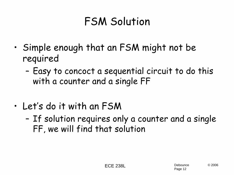
FSM Solution
• Simple enough that an FSM might not be required– Easy to concoct a sequential circuit to do this
with a counter and a single FF
• Let’s do it with an FSM– If solution requires only a counter and a single
FF, we will find that solution

DebouncePage 13
ECE 238L © 2006
Draw a Timing Diagram
noisy
debounced
time
5ms 5ms

DebouncePage 14
ECE 238L © 2006
Draw a System Block Diagram
FiniteState
Machine
clk reset
noisy debounced
clrTimer Timer(5ms)timerDone
clk
Very reminiscent of our car wash controller…

DebouncePage 15
ECE 238L © 2006
The Design of the FSM

DebouncePage 16
ECE 238L © 2006
Draw a State Graph
S2
S3
noisy
noisy’
noisy•timerDone’
noisy
clrTimer
noisy’
noisy•timerDone
debouncedclrTimer
noisy’
S0
noisy’•timerDone’
noisy’•timerDone
noisydebounced S1

DebouncePage 17
ECE 238L © 2006
Draw a State Graph
S2
S3
noisy
noisy’
noisy’
noisy•timerDone’
noisy
clrTimer
noisy•timerDone
debouncedclrTimer
noisy’
S0
noisy’•timerDone’
noisy’•timerDone
noisydebounced S1
Debounced outputis low…

DebouncePage 18
ECE 238L © 2006
Debounced outputis high…
Draw a State Graph
S2
S3
noisy
noisy’
noisy’
noisy•timerDone’
noisy
clrTimer
noisy•timerDone
debouncedclrTimer
noisy’
S0
noisy’•timerDone’
noisy’•timerDone
noisydebounced S1
DebouncePage 19
ECE 238L © 2006
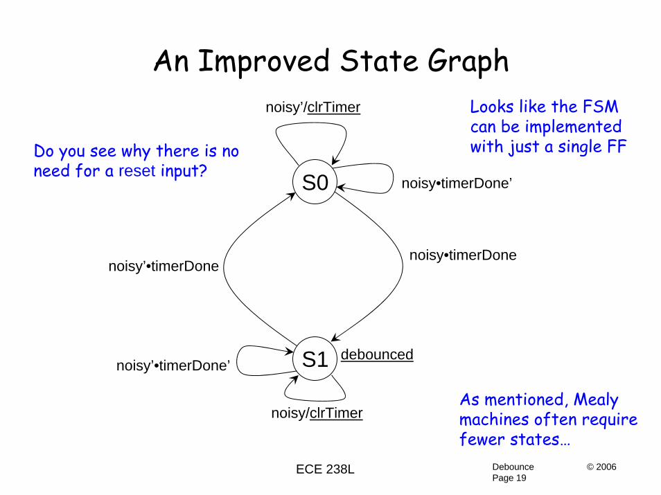
An Improved State Graph
S1
noisy’/clrTimer
noisy/clrTimer
noisy•timerDone
debounced
S0
noisy’•timerDone
noisy’•timerDone’
noisy•timerDone’
As mentioned, Mealymachines often requirefewer states…
Looks like the FSMcan be implementedwith just a single FFDo you see why there is no
need for a reset input?

DebouncePage 20
ECE 238L © 2006
Reduce FSM to LogicNS = CS’•noisy•timerDone + CS•noisy + CS•noisy’•timerDone’
S0 = CS’ S1 = CS noisy = N timerDone = T
NTCS 00 01 11 10
0
1
1
11 1
NS = noisy•timerDone + CS•timerDone’
clrTimer = noisy’•CS’ + noisy•CS
debounced = CS

DebouncePage 21
ECE 238L © 2006
Reduce FSM to Logic
This is smaller than one-hot implementation
In addition, the one-hot would require a reset input to get it to state S0
debounced == CSD Q
clrTimer
noisy
timerDone
CS
noisy
NS = noisy•timerDone + CS•timerDone’
clrTimer = noisy’•CS’ + noisy•CS
debounced = CS

DebouncePage 22
ECE 238L © 2006
noisy is an Asynchronous Input
If less than 20ns wide, FSM may not see it
• Signal noisy is asynchronous– No restrictions on pulse widths
• We will live with this possibility…

DebouncePage 23
ECE 238L © 2006
More on Asynchronous Input
FiniteState
Machine
clk reset
noisy debounced
clrTimer Timer(5ms)timerDone
clk
Classical asynch input handling problem:1. FSM may see noisy change and change state2. Timer may not see clrTimer that results
Or, the other way around may occur…
Will this cause incorrect operation?

DebouncePage 24
ECE 238L © 2006
Asynch Input Problem
S1
noisy’/clrTimer
noisy/clrTimer
noisy•timerDone
debounced
S0
noisy’•timerDone
noisy’•timerDone’
noisy•timerDone’
Look at the transitions –will previous slide’sproblem cause a malfunction??
If you determine thata problem may result,what is easiest way tosolve the problem?

DebouncePage 25
ECE 238L © 2006
Design of the Timer

DebouncePage 26
ECE 238L © 2006
Timer Calculations
• Assume system runs at 50MHz (20ns period)• 5ms/20ns = 250,000• An 18-bit counter will work…• 218 is a bit longer than 250,000 (262,144)
– But is close enough to 5ms for our purposes

DebouncePage 27
ECE 238L © 2006
Timer Structure
• 19 inputs: 18 CS bits + 1 clrTimer bit– Very, very large truth table
• A better structure is:– Register that selects between CS+1 and 0
• This is the technique of Chapter 12 (registers)

DebouncePage 28
ECE 238L © 2006
Timer Structure
+1 0
10
clrTimer
18timerDone
1818
D Q
clk
18
18 18-inputAND

DebouncePage 29
ECE 238L © 2006
Improved Timer Structure
+1clrTimer
18timerDone18
D Q
clk
18
18 18-inputAND18
This is a simpler way to conditionally generate zeroes.
A synthesizer likely would have generated this from Verilog orVHDL code containing a MUX

DebouncePage 30
ECE 238L © 2006
Building the +1 Circuit – Version #1
d17-d0
”000000000000000001” output
The adder would be builtas outlined back in Chapter 8using full adder blocks.
However, half the full adderinputs will be ‘0’ – there oughtto be a better way…

DebouncePage 31
ECE 238L © 2006
A Full-Adder with ‘0’ InputsS
A‘0’Cin
Cout
A‘0’‘0’
CinA
Cin
Full Adder Cout‘0’
'0'
ACin
ACin
Cout
SA
Cin

DebouncePage 32
ECE 238L © 2006
A Half-AdderS
A‘0’Cin
Cout
A‘0’‘0’
CinA
Cin
Full Adder Cout‘0’
'0'
ACin
ACin
Cout
SA
Cin
Called a half-adder
Will add 2 bits togetherand generate sum and carry.

DebouncePage 33
ECE 238L © 2006
Building the +1 Circuit - Version #2
HalfAdder
A0
S0
C0 ‘1’HalfAdder
A1
S1
C1HalfAdder
A2
S2
C2
Half-adders add A’s and carries‘1’ on right end is the +1
DebouncePage 34
ECE 238L © 2006
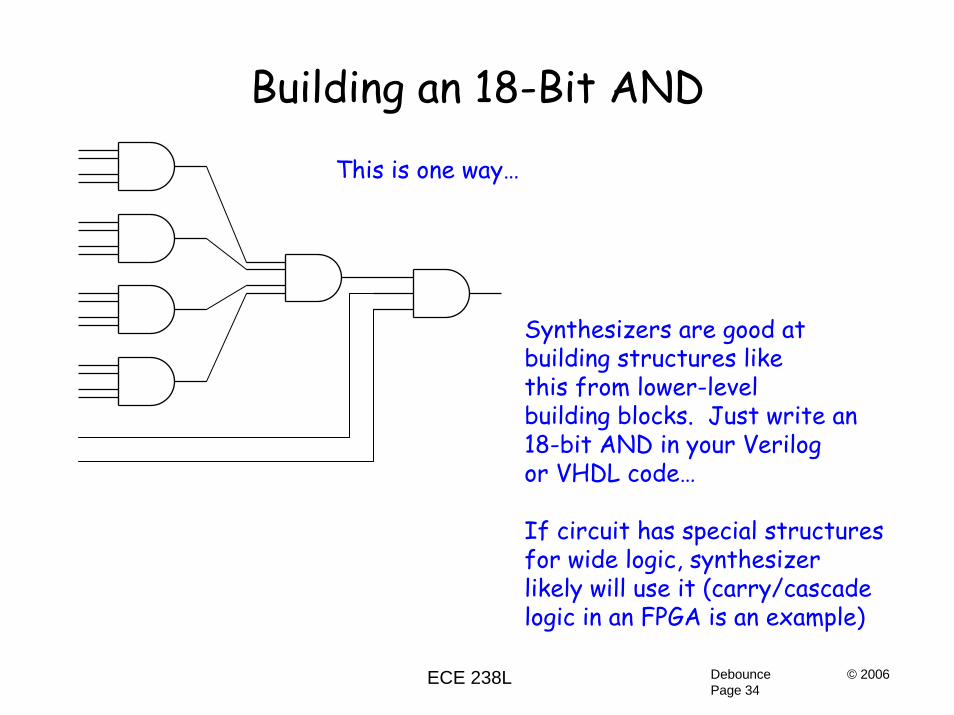
Building an 18-Bit AND
This is one way…
Synthesizers are good atbuilding structures likethis from lower-levelbuilding blocks. Just write an18-bit AND in your Verilogor VHDL code…
If circuit has special structures for wide logic, synthesizer likely will use it (carry/cascadelogic in an FPGA is an example)
DebouncePage 35
ECE 238L © 2006
Debouncer Summary
• Structure is timer + FSM• 2-state FSM makes NS logic trivial• Asynchronous input makes it possible (but
unlikely) to miss a glitch on input noisy– If desired, synchronize noisy with a FF
• Counter too large for conventional techniques– Use MUX+register techniques of Chapter 12
• NOTE: FSM technique resulted in FF+countermentioned previously…
Top Related